Embed Size (px)
Citation preview
163
Fig. 12.4: Pitot tube sensor FTHD-36, shown in a horizontal installation for horizontal or
vertical pipe runs.
12.1 Model Series FTHD to 588 psi (PN 40)
Description
The ITABAR-sensor series FTHD is designed to measure volumetric flow of saturated and super heated steam.
The sensor construction features a flanged connection between the pipe and the sensor-related parts, a compression fitting to seal the sensor and a gate valve to insert the sensor profile into the pipe.
The sensor can be used at an operating pressure of up to 588 psi (40 bar) and an operating temperature of up to 400°C / 752°F.
The insertion or removal of the sensor is made easy by two guide-rod spindles or (as an option) via a hand wheel driven gearbox.
Fig. 12.3: : Pitot tube sensor FTHD-36 made of st. steel for a pipe with ID = 336.5 mm
164
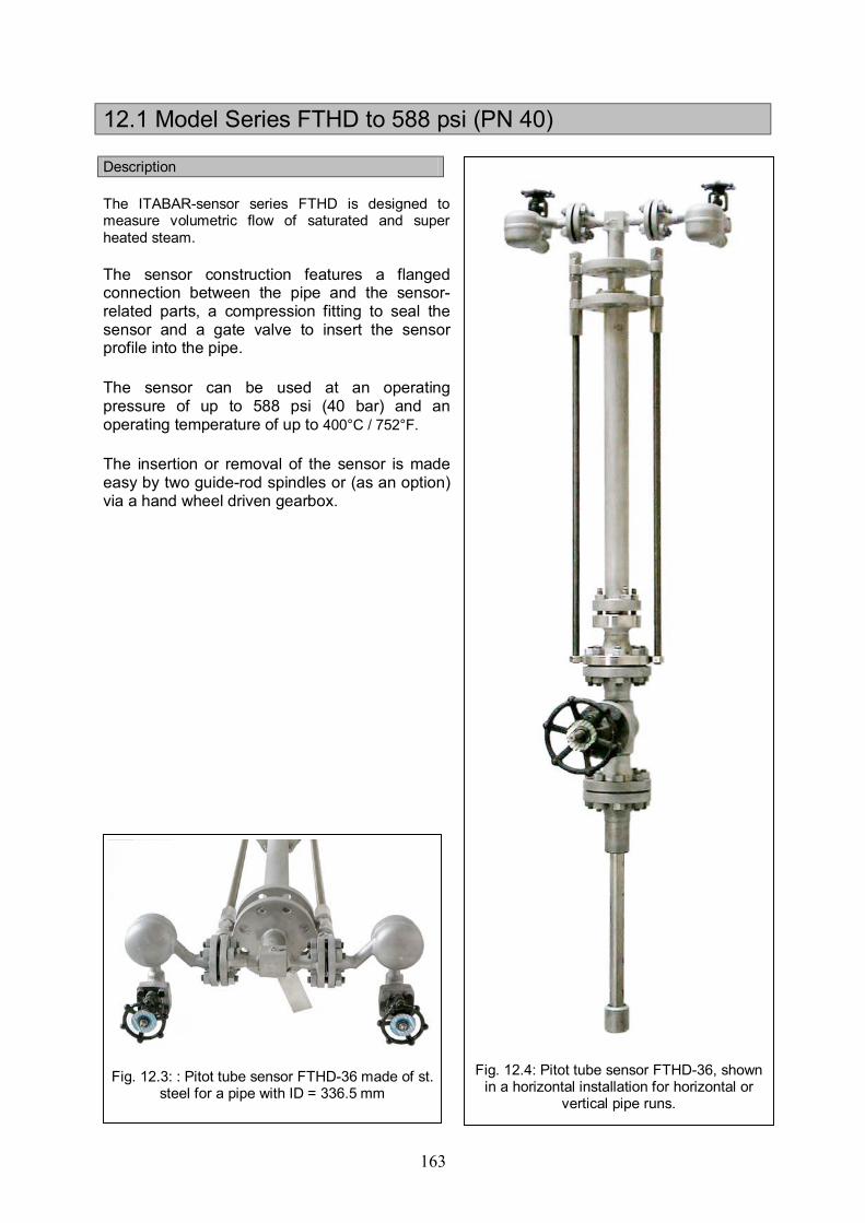
Drawings für ITABAR Series FTHD
165
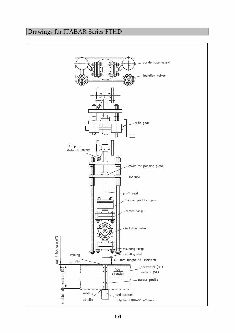
Order Data for ITABAR Series FTHD-20/21/25/26/35/36
1. Sensor Type
Maximum allowable volumetric flow in GPM
Sensor type Pipe diameter
(inches) FTHD -20 FTHD -21 FTHD -25 FTHD -26 FTHD -35 FTHD -36
1 1/2 175 502 --- --- --- --- 2 260 708 --- --- --- ---
2 1/4 409 1069 --- --- --- --- 3 572 1443 --- --- --- --- 4 787 1936 902 2398 --- --- 5 1047 2512 1240 3168 --- --- 6 --- --- 1579 3938 --- --- 8 --- --- 2270 5473 --- ---
10 --- --- 3027 7150 --- --- 12 --- --- 3841 8962 7739 18519 14 --- --- 4637 10718 9438 22321 16 --- --- 5403 12460 11154 26158 20 --- --- 7013 15976 14462 33528 24 --- --- 8588 19483 17850 41087 28 --- --- 10212 23069 21370 48923 32 --- --- 11910 26870 24965 56962 36 --- --- --- 30839 --- 65155 40 --- --- --- 34896 --- 73189 48 --- --- --- 43010 --- 90090 56 --- --- --- 50965 --- 106695 64 --- --- --- 58656 --- 123292 72 --- --- --- 66255 --- 139264 80 --- --- --- --- --- ---
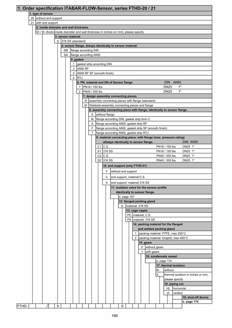
1. Order specification ITABAR-FLOW-Sensor, series FTHD-20 / 211. type of sensor20 without end support21 with end support
2. inside diameter and wall thickness.ID / W.-thickn. inside diameter and wall thickness in inches (or mm), please specify
3. sensor materialS 316 SS (standard)
4. sensor flange, always identically to sensor material.SM flange according DINSA flange according ANSI
5. gasket1 gasket strip according DIN2 ANSI RF3 ANSI RF SF (smooth finish)4 RTJ
6. PN, material and DN of Sensor flange DIN ANSI1 PN16 / 150 lbs DN25 1"2 PN40 / 300 lbs DN25 1"
7. design assembly connecting piecesR assembly connecting pieces with flange (standard)W Weldolet-assembly connecting pieces and flange
8. assembly connecting piece with flange, identically to sensor flange.0 without flangeM flange according DIN, gasket strip form CA flange according ANSI, gasket strip RFF flange according ANSI, gasket strip SF (smooth finish)T flange according ANSI, gasket strip RTJ
9. material connecting piece, with flange (max. pressure rating)allways identically to sensor flange. DIN ANSI
C1 C.S. PN16 / 150 lbs DN25 1"S1 316 SS PN16 / 150 lbs DN25 1"C2 C.S. PN40 / 300 lbs DN25 1"S2 316 SS PN40 / 300 lbs DN25 1"
10. end support (only FTHD-21)
Y without end support
C end support, material:C.S.
S end support, material 316 SS11. isolation valve for the sensor profile identically to sensor flange.
s. page 16712. flanged packing gland
S material: 316 SS13. cage nipplePC material; C.S.PS material: 316 SS
14. packing material for the flanged and welded packing gland
1 packing material: PTFE, max 200°C2 packing material: Graphit, max 400°C
15. gears0 without gears1 with gears
16. condensate vessels. page 17417. thermal isolationKI withoutX.. thermal isolation in inches or mm,
please specify18. piping run
HL horizontalVL vertikal
19. shut-off devices. page 174
FTHD- S S
166
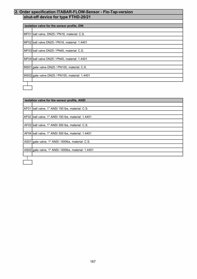
2. Order specification ITABAR-FLOW-Sensor - Flo-Tap-versionshut-off device for type FTHD-20/21
isolation valve for the sensor profile, DIN
MF01 ball valve, DN25 / PN16, material: C.S.
MF02 ball valve DN25 / PN16, material: 1.4401
MF03 ball valve DN25 / PN40, material: C.S.
MF04 ball valve DN25 / PN40, material: 1.4401
MS01 gate valve DN25 / PN100, material: C.S.
MS02 gate valve DN25 / PN100, material: 1.4401
isolation valve for the sensor profile, ANSI
AF01 ball valve, 1" ANSI 150 lbs, material: C.S.
AF02 ball valve, 1" ANSI 150 lbs, material: 1.4401
AF03 ball valve, 1" ANSI 300 lbs, material: C.S.
AF04 ball valve, 1" ANSI 300 lbs, material: 1.4401
AS01 gate valve, 1" ANSI / 600lbs, material: C.S.
AS02 gate valve, 1" ANSI / 600lbs, material: 1.4401
167
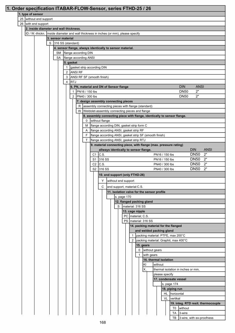
1. Order specification ITABAR-FLOW-Sensor, series FTHD-25 / 261. type of sensor25 without end support26 with end support
2. inside diameter and wall thickness.ID / W.-thickn. inside diameter and wall thickness in inches (or mm), please specify
3. sensor materialS 316 SS (standard)
4. sensor flange, always identically to sensor material.SM flange according DINSA flange according ANSI
5. gasket1 gasket strip according DIN2 ANSI RF3 ANSI RF SF (smooth finish)4 RTJ
6. PN, material and DN of Sensor flange DIN ANSI1 PN16 / 150 lbs DN50 2"2 PN40 / 300 lbs DN50 2"
7. design assembly connecting piecesR assembly connecting pieces with flange (standard)W Weldolet-assembly connecting pieces and flange
8. assembly connecting piece with flange, identically to sensor flange.0 without flangeM flange according DIN, gasket strip form CA flange according ANSI, gasket strip RFF flange according ANSI, gasket strip SF (smooth finish)T flange according ANSI, gasket strip RTJ
9. material connecting piece, with flange (max. pressure rating)allways identically to sensor flange. DIN ANSI
C1 C.S. PN16 / 150 lbs DN50 2"S1 316 SS PN16 / 150 lbs DN50 2"C2 C.S. PN40 / 300 lbs DN50 2"S2 316 SS PN40 / 300 lbs DN50 2"
10. end support (only FTHD-26)
Y without end support
C end support, material:C.S.11. isolation valve for the sensor profile
s. page 17012. flanged packing gland
S material: 316 SS13. cage nipplePC material; C.S.PS material: 316 SS
14. packing material for the flanged and welded packing gland
1 packing material: PTFE, max 200°C2 packing material: Graphit, max 400°C
15. gears0 without gears1 with gears
16. thermal isolationKI withoutX.. thermal isolation in inches or mm,
please specify17. condensate vessel
s. page 17418. piping run
HL horizontalVL vertikal
19. integ. RTD resit. thermocoupleT0 withoutTA 3-wireTB 3-wire, with ex-proofness
168
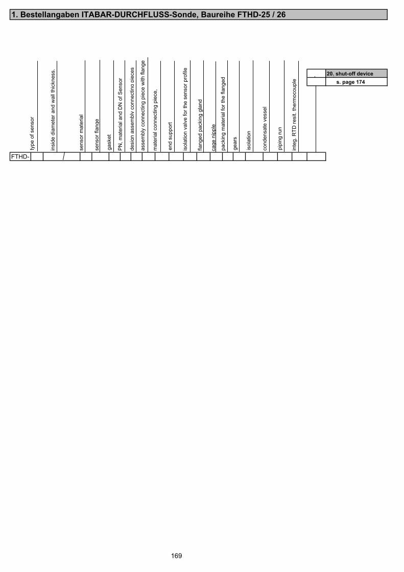
1. Bestellangaben ITABAR-DURCHFLUSS-Sonde, Baureihe FTHD-25 / 26
20. shut-off devices. page 174
FTHD-
169
type
of s
enso
r
insi
de d
iam
eter
and
wal
l thi
ckne
ss.
sens
or m
ater
ial
sens
or fl
ange
gask
et
PN, m
ater
ial a
nd D
N o
f Sen
sor
desi
gn a
ssem
bly
conn
ectin
gpi
eces
asse
mbl
y co
nnec
ting
piec
e w
ith fl
ange
mat
eria
l con
nect
ing
piec
e,
end
supp
ort
isol
atio
n va
lve
for t
he s
enso
r pro
file
flan
ged
pack
ing
glan
d
cage
nip
ple
pack
ing
mat
eria
l for
the
flang
ed
gear
s
isol
atio
n
cond
ensa
te v
esse
l
pipi
ng ru
n
inte
g. R
TD re
sit.
ther
moc
oupl
e
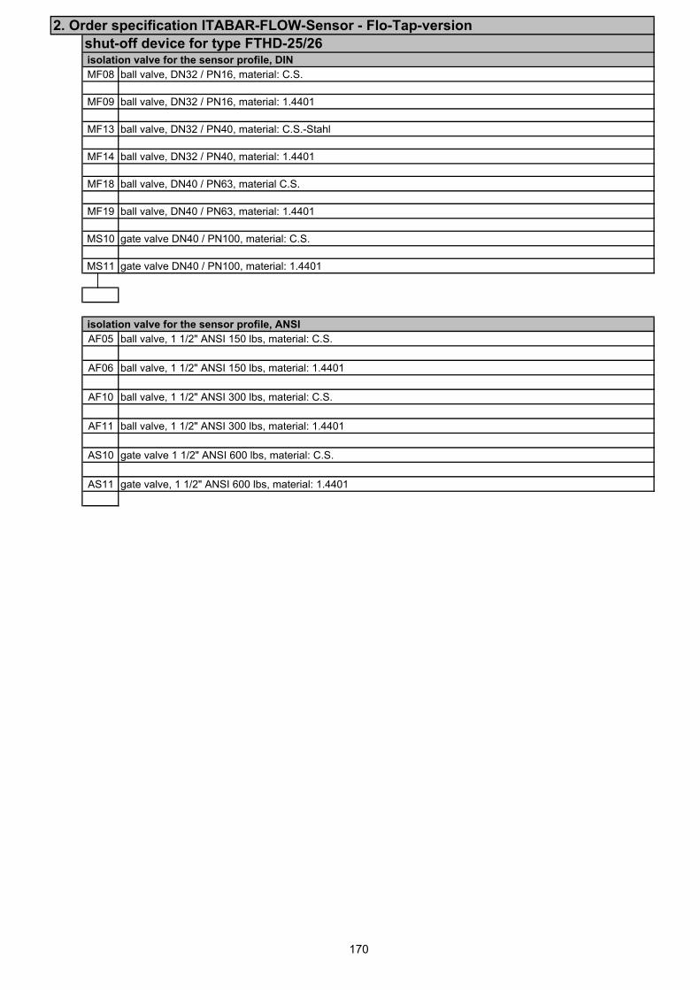
2. Order specification ITABAR-FLOW-Sensor - Flo-Tap-versionshut-off device for type FTHD-25/26 isolation valve for the sensor profile, DINMF08 ball valve, DN32 / PN16, material: C.S.
MF09 ball valve, DN32 / PN16, material: 1.4401
MF13 ball valve, DN32 / PN40, material: C.S.-Stahl
MF14 ball valve, DN32 / PN40, material: 1.4401
MF18 ball valve, DN40 / PN63, material C.S.
MF19 ball valve, DN40 / PN63, material: 1.4401
MS10 gate valve DN40 / PN100, material: C.S.
MS11 gate valve DN40 / PN100, material: 1.4401
isolation valve for the sensor profile, ANSIAF05 ball valve, 1 1/2" ANSI 150 lbs, material: C.S.
AF06 ball valve, 1 1/2" ANSI 150 lbs, material: 1.4401
AF10 ball valve, 1 1/2" ANSI 300 lbs, material: C.S.
AF11 ball valve, 1 1/2" ANSI 300 lbs, material: 1.4401
AS10 gate valve 1 1/2" ANSI 600 lbs, material: C.S.
AS11 gate valve, 1 1/2" ANSI 600 lbs, material: 1.4401
170
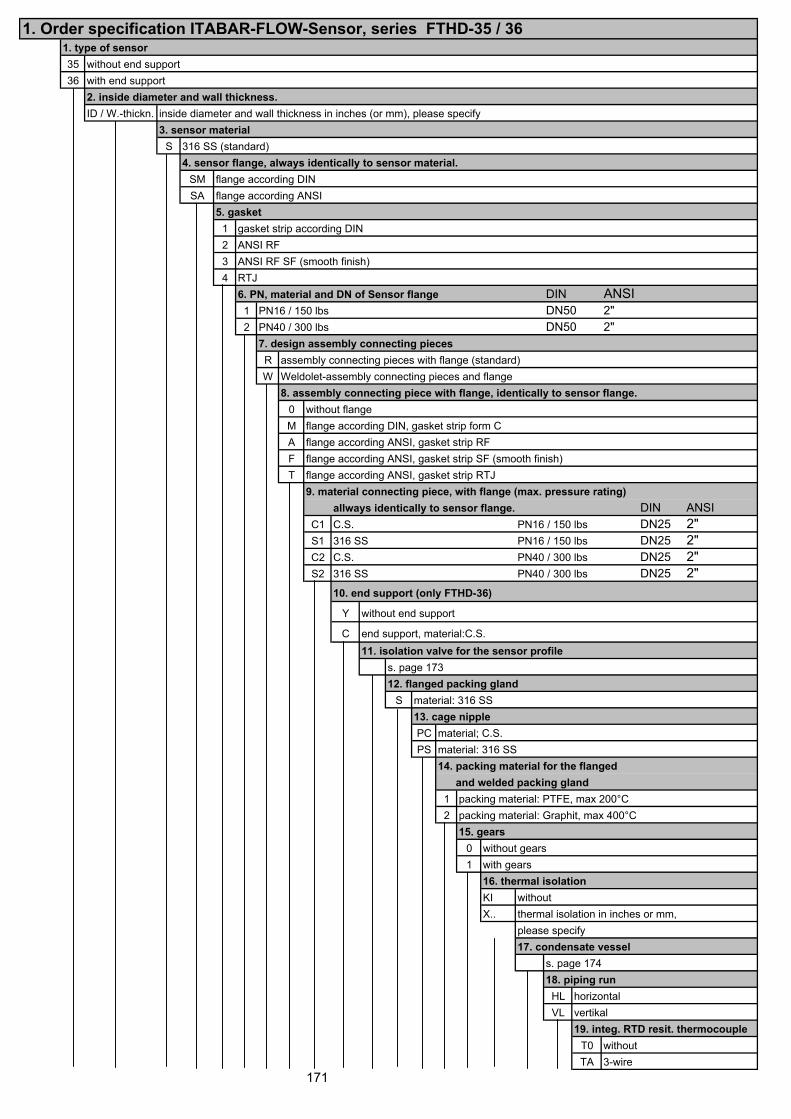
1. Order specification ITABAR-FLOW-Sensor, series FTHD-35 / 361. type of sensor35 without end support36 with end support
2. inside diameter and wall thickness.ID / W.-thickn. inside diameter and wall thickness in inches (or mm), please specify
3. sensor materialS 316 SS (standard)
4. sensor flange, always identically to sensor material.SM flange according DINSA flange according ANSI
5. gasket1 gasket strip according DIN2 ANSI RF3 ANSI RF SF (smooth finish)4 RTJ
6. PN, material and DN of Sensor flange DIN ANSI1 PN16 / 150 lbs DN50 2"2 PN40 / 300 lbs DN50 2"
7. design assembly connecting piecesR assembly connecting pieces with flange (standard)W Weldolet-assembly connecting pieces and flange
8. assembly connecting piece with flange, identically to sensor flange.0 without flangeM flange according DIN, gasket strip form CA flange according ANSI, gasket strip RFF flange according ANSI, gasket strip SF (smooth finish)T flange according ANSI, gasket strip RTJ
9. material connecting piece, with flange (max. pressure rating)allways identically to sensor flange. DIN ANSI
C1 C.S. PN16 / 150 lbs DN25 2"S1 316 SS PN16 / 150 lbs DN25 2"C2 C.S. PN40 / 300 lbs DN25 2"S2 316 SS PN40 / 300 lbs DN25 2"
10. end support (only FTHD-36)
Y without end support
C end support, material:C.S.11. isolation valve for the sensor profile
s. page 17312. flanged packing gland
S material: 316 SS13. cage nipplePC material; C.S.PS material: 316 SS
14. packing material for the flanged and welded packing gland1 packing material: PTFE, max 200°C2 packing material: Graphit, max 400°C
15. gears0 without gears1 with gears
16. thermal isolationKI withoutX.. thermal isolation in inches or mm,
please specify17. condensate vessel
s. page 17418. piping runHL horizontalVL vertikal
19. integ. RTD resit. thermocoupleT0 withoutTA 3-wire
171
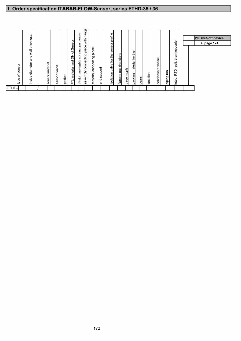
1. Order specification ITABAR-FLOW-Sensor, series FTHD-35 / 36
20. shut-off devices. page 174
FTHD-
172
type
of s
enso
r
insi
de d
iam
eter
and
wal
l thi
ckne
ss.
sens
or m
ater
ial
sens
or fl
ange
gask
et
PN, m
ater
ial a
nd D
N o
f Sen
sor
desi
gnas
sem
bly
conn
ectin
gpi
eces
asse
mbl
y co
nnec
ting
piec
e w
ith fl
ange
mat
eria
l con
nect
ing
piec
e,
end
supp
ort
isol
atio
n va
lve
for t
he s
enso
r pro
file
flan
ged
pack
ing
glan
d
cage
nip
ple
pack
ing
mat
eria
l for
the
gear
s
isol
atio
n
pipi
ng ru
n
inte
g. R
TD re
sit.
ther
moc
oupl
e
cond
ensa
te v
esse
l
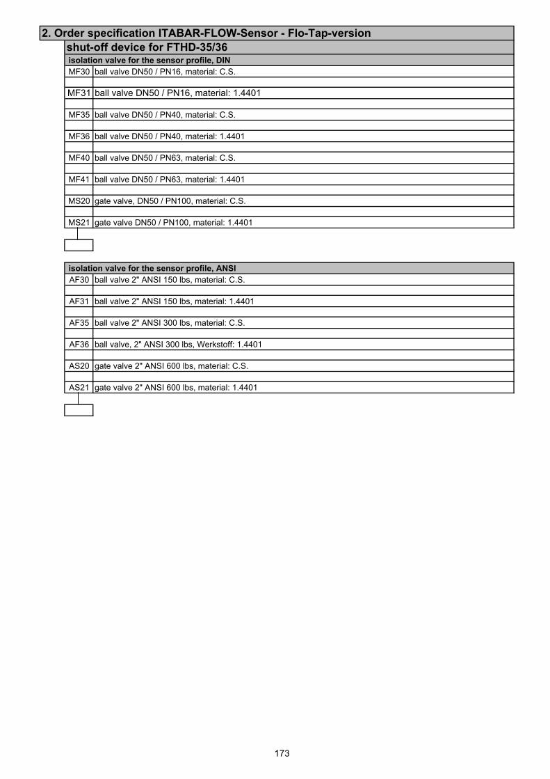
2. Order specification ITABAR-FLOW-Sensor - Flo-Tap-versionshut-off device for FTHD-35/36 isolation valve for the sensor profile, DINMF30 ball valve DN50 / PN16, material: C.S.
MF31 ball valve DN50 / PN16, material: 1.4401
MF35 ball valve DN50 / PN40, material: C.S.
MF36 ball valve DN50 / PN40, material: 1.4401
MF40 ball valve DN50 / PN63, material: C.S.
MF41 ball valve DN50 / PN63, material: 1.4401
MS20 gate valve, DN50 / PN100, material: C.S.
MS21 gate valve DN50 / PN100, material: 1.4401
isolation valve for the sensor profile, ANSIAF30 ball valve 2" ANSI 150 lbs, material: C.S.
AF31 ball valve 2" ANSI 150 lbs, material: 1.4401
AF35 ball valve 2" ANSI 300 lbs, material: C.S.
AF36 ball valve, 2" ANSI 300 lbs, Werkstoff: 1.4401
AS20 gate valve 2" ANSI 600 lbs, material: C.S.
AS21 gate valve 2" ANSI 600 lbs, material: 1.4401
173
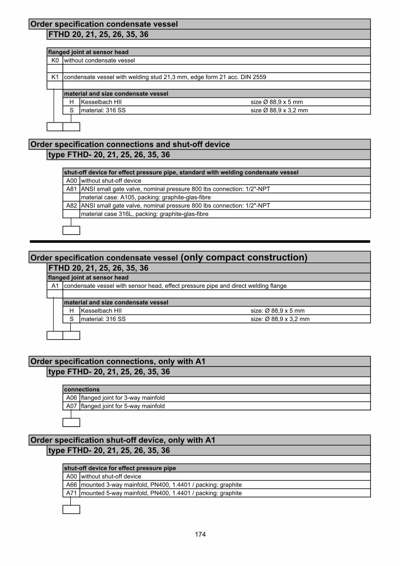
Order specification condensate vesselFTHD 20, 21, 25, 26, 35, 36
flanged joint at sensor headK0 without condensate vessel
K1 condensate vessel with welding stud 21,3 mm, edge form 21 acc. DIN 2559
material and size condensate vesselH Kesselbach HII size Ø 88,9 x 5 mmS material: 316 SS size Ø 88,9 x 3,2 mm
Order specification connections and shut-off devicetype FTHD- 20, 21, 25, 26, 35, 36
shut-off device for effect pressure pipe, standard with welding condensate vesselA00 without shut-off deviceA81 ANSI small gate valve, nominal pressure 800 lbs connection: 1/2"-NPT
material case: A105, packing: graphite-glas-fibreA82 ANSI small gate valve, nominal pressure 800 lbs connection: 1/2"-NPT
material case 316L, packing: graphite-glas-fibre
Order specification condensate vessel (only compact construction)FTHD 20, 21, 25, 26, 35, 36flanged joint at sensor headA1 condensate vessel with sensor head, effect pressure pipe and direct welding flange
material and size condensate vesselH Kesselbach HII size: Ø 88,9 x 5 mmS material: 316 SS size: Ø 88,9 x 3,2 mm
Order specification connections, only with A1type FTHD- 20, 21, 25, 26, 35, 36
connectionsA06 flanged joint for 3-way mainfoldA07 flanged joint for 5-way mainfold
Order specification shut-off device, only with A1type FTHD- 20, 21, 25, 26, 35, 36
shut-off device for effect pressure pipeA00 without shut-off deviceA66 mounted 3-way mainfold, PN400, 1.4401 / packing: graphiteA71 mounted 5-way mainfold, PN400, 1.4401 / packing: graphite
174
175
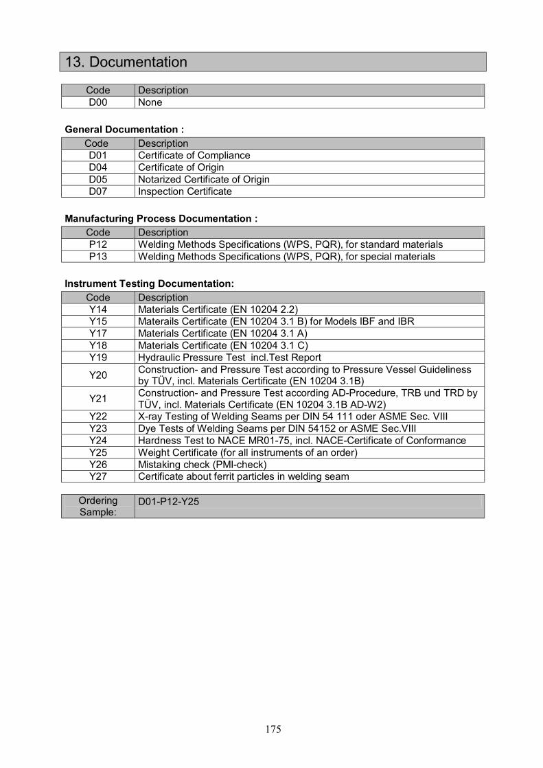
13. Documentation
Code Description D00 None
General Documentation : Code Description
D01 Certificate of Compliance D04 Certificate of Origin D05 Notarized Certificate of Origin D07 Inspection Certificate
Manufacturing Process Documentation : Code Description P12 Welding Methods Specifications (WPS, PQR), for standard materials P13 Welding Methods Specifications (WPS, PQR), for special materials
Instrument Testing Documentation: Code Description Y14 Materials Certificate (EN 10204 2.2) Y15 Materails Certificate (EN 10204 3.1 B) for Models IBF and IBR Y17 Materials Certificate (EN 10204 3.1 A) Y18 Materials Certificate (EN 10204 3.1 C) Y19 Hydraulic Pressure Test incl.Test Report
Y20 Construction- and Pressure Test according to Pressure Vessel Guideliness by TÜV, incl. Materials Certificate (EN 10204 3.1B)
Y21 Construction- and Pressure Test according AD-Procedure, TRB und TRD by TÜV, incl. Materials Certificate (EN 10204 3.1B AD-W2)
Y22 X-ray Testing of Welding Seams per DIN 54 111 oder ASME Sec. VIII Y23 Dye Tests of Welding Seams per DIN 54152 or ASME Sec.VIII Y24 Hardness Test to NACE MR01-75, incl. NACE-Certificate of Conformance Y25 Weight Certificate (for all instruments of an order) Y26 Mistaking check (PMI-check) Y27 Certificate about ferrit particles in welding seam
Ordering Sample:
D01-P12-Y25