Embed Size (px)
Citation preview
1200 IEEE TRANSACTIONS ON IMAGE PROCESSING, VOL. 13, NO. 9, SEPTEMBER 2004
Region Filling and Object Removal byExemplar-Based Image Inpainting
Antonio Criminisi, Patrick Pérez, and Kentaro Toyama
Abstract—A new algorithm is proposed for removing large ob-jects from digital images. The challenge is to fill in the hole that isleft behind in a visually plausible way. In the past, this problem hasbeen addressed by two classes of algorithms: 1) “texture synthesis”algorithms for generating large image regions from sample tex-tures and 2) “inpainting” techniques for filling in small image gaps.The former has been demonstrated for “textures”—repeating two-dimensional patterns with some stochasticity; the latter focus onlinear “structures” which can be thought of as one-dimensionalpatterns, such as lines and object contours. This paper presentsa novel and efficient algorithm that combines the advantages ofthese two approaches. We first note that exemplar-based texturesynthesis contains the essential process required to replicate bothtexture and structure; the success of structure propagation, how-ever, is highly dependent on the order in which the filling proceeds.We propose a best-first algorithm in which the confidence in thesynthesized pixel values is propagated in a manner similar to thepropagation of information in inpainting. The actual color valuesare computed using exemplar-based synthesis. In this paper, thesimultaneous propagation of texture and structure information isachieved by a single, efficient algorithm. Computational efficiencyis achieved by a block-based sampling process. A number of exam-ples on real and synthetic images demonstrate the effectiveness ofour algorithm in removing large occluding objects, as well as thinscratches. Robustness with respect to the shape of the manuallyselected target region is also demonstrated. Our results comparefavorably to those obtained by existing techniques.
Index Terms—Image inpainting, object removal, simultaneoustexture and structure propagation, texture synthesis.
I. INTRODUCTION
THIS PAPER presents a novel algorithm for removing largeobjects from digital photographs and replacing them with
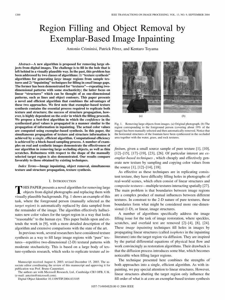
visually plausible backgrounds. Fig. 1 shows an example of thistask, where the foreground person (manually selected as thetarget region) is automatically replaced by data sampled fromthe remainder of the image. The algorithm effectively halluci-nates new color values for the target region in a way that looks“reasonable” to the human eye. This paper builds upon and ex-tends the work in [9], with a more detailed description of thealgorithm and extensive comparisons with the state of the art.
In previous work, several researchers have considered texturesynthesis as a way to fill large image regions with “pure” tex-tures—repetitive two-dimensional (2-D) textural patterns withmoderate stochasticity. This is based on a large body of tex-ture-synthesis research, which seeks to replicate texture ad in-
Manuscript received August 6, 2003; revised December 15, 2003. The as-sociate editor coordinating the review of this manuscript and approving it forpublication was Prof. Bruno Carpentieri.
The authors are with Microsoft Research, Ltd., Cambridge CB3 OFB, U.K.(e-mail: [email protected]).
Digital Object Identifier 10.1109/TIP.2004.833105
Fig. 1. Removing large objects from images. (a) Original photograph. (b) Theregion corresponding to the foreground person (covering about 19% of theimage) has been manually selected and then automatically removed. Notice thatthe horizontal structures of the fountain have been synthesized in the occludedarea together with the water, grass, and rock textures.
finitum, given a small source sample of pure texture [1], [10],[12]–[15], [17]–[19], [23], [26]. Of particular interest are ex-emplar-based techniques , which cheaply and effectively gen-erate new texture by sampling and copying color values fromthe source [1], [12]–[14], [18].
As effective as these techniques are in replicating consis-tent texture, they have difficulty filling holes in photographs ofreal-world scenes, which often consist of linear structures andcomposite textures—multiple textures interacting spatially [27].The main problem is that boundaries between image regionsare a complex product of mutual influences between differenttextures. In constrast to the 2-D nature of pure textures, theseboundaries form what might be considered more one-dimen-sional (1-D), or linear, image structures.
A number of algorithms specifically address the imagefilling issue for the task of image restoration, where speckles,scratches, and overlaid text are removed [2]–[4], [8], [24].These image inpainting techniques fill holes in images bypropagating linear structures (called isophotes in the inpaintingliterature) into the target region via diffusion. They are inspiredby the partial differential equations of physical heat flow andwork convincingly as restoration algorithms. Their drawback isthat the diffusion process introduces some blur, which becomesnoticeable when filling larger regions.
The technique presented here combines the strengths ofboth approaches into a single, efficient algorithm. As with in-painting, we pay special attention to linear structures. However,linear structures abutting the target region only influence thefill order of what is at core an exemplar-based texture synthesis
1057-7149/04$20.00 © 2004 IEEE
CRIMINISI et al.: REGION FILLING AND OBJECT REMOVAL 1201
algorithm. The result is an algorithm that has the efficiency andqualitative performance of exemplar-based texture synthesis,but which also respects the image constraints imposed bysurrounding linear structures.
The algorithm we propose in this paper builds on very recentresearch along similar lines. The work in [5] decomposes theoriginal image into two components, one of which is processedby inpainting and the other by texture synthesis. The outputimage is the sum of the two processed components. This ap-proach still remains limited to the removal of small image gaps,however, as the diffusion process continues to blur the filled re-gion (cf., [5]). The automatic switching between “pure texture-”and “pure structure-mode” of [25] is also avoided.
Similar to [5] is the work in [11], where the authors describean algorithm that interleaves a smooth approximation with ex-ample-based detail synthesis for image completion. Like thework in [5], the algorithm in [11] is also extremely slow (asreported, processing may take between 83 and 158 minutes ona 384 256 image) and it may introduce blur artefacts [11]. Inthis paper, we present a simpler and faster region filling algo-rithm which does not suffer from blur artefacts.
One of the first attempts to use exemplar-based synthesisspecifically for object removal was by Harrison [16]. There, theorder in which a pixel in the target region is filled was dictatedby the level of “texturedness” of the pixel’s neighborhood.1
Although the intuition is sound, strong linear structures wereoften overruled by nearby noise, minimizing the value of theextra computation. A related technique drove the fill order bythe local shape of the target region, but did not seek to explicitlypropagate linear structures [6].
Recently, Jia et al. [20] have presented a technique for fillingimage regions based on a texture-segmentation step and atensor-voting algorithm for the smooth linking of structuresacross holes. Their approach has a clear advantage in that it isdesigned to connect curved structures by the explicit genera-tion of subjective contours, over which textural structures arepropagated. On the other hand, their algorithm requires 1) anexpensive segmentation step and 2) a hard decision about whatconstitutes a boundary between two textures. Our approachavoids both issues through the use of a continuous parameterbased on local gradient strength only. A careful fusion of theseapproaches may result in a superior algorithm, but results sug-gest that both approaches already achieve a reasonable measureof visual credibility in filling holes.
Finally, Zalesny et al. [27] describe an algorithm for theparallel synthesis of composite textures. They devise a spe-cial-purpose solution for synthesizing the interface betweentwo “knitted” textures. In this paper, we show that, in fact, onlyone mechanism is sufficient for the synthesis of both pure andcomposite textures.
Paper outline. Section II presents the two key observationswhich form the basis of ouralgorithm.The detailsof the proposedalgorithm are described in Section III. Finally, a large galleryof results on both synthetic images and real-scene photographsis presented in Section IV. Whenever possible, our results arecompared to those obtained by state of the art techniques.
1An implementation of Harrison’s algorithm is available from http://www.csse.monash.edu.au/\sim pfh/resynthesizer/.
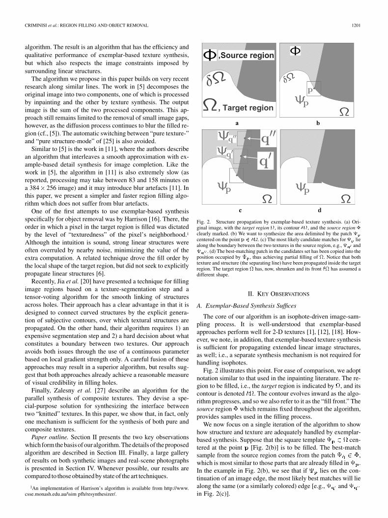
Fig. 2. Structure propagation by exemplar-based texture synthesis. (a) Ori-ginal image, with the target region , its contour �, and the source region �clearly marked. (b) We want to synthesize the area delimited by the patch centered on the point p 2 �. (c) The most likely candidate matches for liealong the boundary between the two textures in the source region, e.g., and . (d) The best-matching patch in the candidates set has been copied into theposition occupied by , thus achieving partial filling of . Notice that bothtexture and structure (the separating line) have been propagated inside the targetregion. The target region has, now, shrunken and its front � has assumed adifferent shape.
II. KEY OBSERVATIONS
A. Exemplar-Based Synthesis Suffices
The core of our algorithm is an isophote-driven image-sam-pling process. It is well-understood that exemplar-basedapproaches perform well for 2-D textures [1], [12], [18]. How-ever, we note, in addition, that exemplar-based texture synthesisis sufficient for propagating extended linear image structures,as well; i.e., a separate synthesis mechanism is not required forhandling isophotes.
Fig. 2 illustrates this point. For ease of comparison, we adoptnotation similar to that used in the inpainting literature. The re-gion to be filled, i.e., the target region is indicated by , and itscontour is denoted . The contour evolves inward as the algo-rithm progresses, and so we also refer to it as the “fill front.” Thesource region which remains fixed throughout the algorithm,provides samples used in the filling process.
We now focus on a single iteration of the algorithm to showhow structure and texture are adequately handled by exemplar-based synthesis. Suppose that the square template cen-tered at the point [Fig. 2(b)] is to be filled. The best-matchsample from the source region comes from the patch ,which is most similar to those parts that are already filled in .In the example in Fig. 2(b), we see that if lies on the con-tinuation of an image edge, the most likely best matches will liealong the same (or a similarly colored) edge [e.g., andin Fig. 2(c)].
1202 IEEE TRANSACTIONS ON IMAGE PROCESSING, VOL. 13, NO. 9, SEPTEMBER 2004
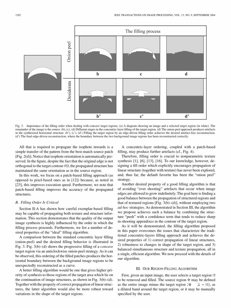
Fig. 3. Importance of the filling order when dealing with concave target regions. (a) A diagram showing an image and a selected target region (in white). Theremainder of the image is the source. (b), (c), (d) Different stages in the concentric-layer filling of the target region. (d) The onion-peel approach produces artefactsin the synthesized horizontal structure. (b’), (c’), (d’) Filling the target region by an edge-driven filling order achieves the desired artefact-free reconstruction.(d’) The final edge-driven reconstruction, where the boundary between the two background image regions has been reconstructed correctly.
All that is required to propagate the isophote inwards is asimple transfer of the pattern from the best-match source patch[Fig. 2(d)]. Notice that isophote orientation is automatically pre-served. In the figure, despite the fact that the original edge is notorthogonal to the target contour , the propagated structure hasmaintained the same orientation as in the source region.
In this work, we focus on a patch-based filling approach (asopposed to pixel-based ones as in [12]) because, as noted in[23], this improves execution speed. Furthermore, we note thatpatch-based filling improves the accuracy of the propagatedstructures.
B. Filling Order Is Critical
Section II-A has shown how careful exemplar-based fillingmay be capable of propagating both texture and structure infor-mation. This section demonstrates that the quality of the outputimage synthesis is highly influenced by the order in which thefilling process proceeds. Furthermore, we list a number of de-sired properties of the “ideal” filling algorithm.
A comparison between the standard concentric layer filling(onion-peel) and the desired filling behavior is illustrated inFig. 3. Fig. 3(b)–(d) shows the progressive filling of a concavetarget region via an anticlockwise onion-peel strategy. As it canbe observed, this ordering of the filled patches produces the hor-izontal boundary between the background image regions to beunexpectedly reconstructed as a curve.
A better filling algorithm would be one that gives higher pri-ority of synthesis to those regions of the target area which lie onthe continuation of image structures, as shown in Fig. 3(b)–(d).Together with the property of correct propagation of linear struc-tures, the latter algorithm would also be more robust towardvariations in the shape of the target regions.
A concentric-layer ordering, coupled with a patch-basedfilling, may produce further artefacts (cf., Fig. 4).
Therefore, filling order is crucial to nonparametric texturesynthesis [1], [6], [13], [16]. To our knowledge, however, de-signing a fill order which explicitly encourages propagation oflinear structure (together with texture) has never been explored,and, thus far, the default favorite has been the “onion peel”strategy.
Another desired property of a good filling algorithm is thatof avoiding “over shooting” artefacts that occur when imageedges are allowed to grow indefinitely. The goal here is finding agood balance between the propagation of structured regions andthat of textured regions [Fig. 3(b)–(d)], without employing twoad-hoc strategies. As demonstrated in Section III, the algorithmwe propose achieves such a balance by combining the struc-ture “push” with a confidence term that tends to reduce sharpin-shooting appendixes in the contour of the target region.
As it will be demonstrated, the filling algorithm proposedin this paper overcomes the issues that characterize the tradi-tional concentric-layers filling approach and achieves the de-sired properties of 1) correct propagation of linear structures,2) robustness to changes in shape of the target region, and 3)balanced simultaneous structure and texture propagation, all ina single, efficient algorithm. We now proceed with the details ofour algorithm.
III. OUR REGION-FILLING ALGORITHM
First, given an input image, the user selects a target regionto be removed and filled. The source region may be definedas the entire image minus the target region , asa dilated band around the target region, or it may be manuallyspecified by the user.
CRIMINISI et al.: REGION FILLING AND OBJECT REMOVAL 1203
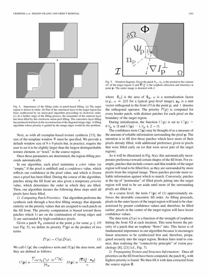
Fig. 4. Importance of the filling order in patch-based filling. (a) The targetregion is shown in white. (b) Part of the outermost layer in the target region hasbeen synthesized by an onion-peel algorithm proceeding in clockwise order.(c) At a further stage of the filling process, the remainder of the outmost layerhas been filled by this clockwise onion-peel filling. The concentric-layer fillinghas produced artefacts in the reconstruction of the diagonal image edge. A fillingalgorithm whose priority is guided by the image edges would fix this problem.
Next, as with all exemplar-based texture synthesis [13], thesize of the template window must be specified. We provide adefault window size of 9 9 pixels but, in practice, require theuser to set it to be slightly larger than the largest distinguishabletexture element, or “texel,” in the source region.
Once these parameters are determined, the region-filling pro-ceeds automatically.
In our algorithm, each pixel maintains a color value (or“empty,” if the pixel is unfilled) and a confidence value, whichreflects our confidence in the pixel value, and which is frozenonce a pixel has been filled. During the course of the algorithm,patches along the fill front are also given a temporary priorityvalue, which determines the order in which they are filled.Then, our algorithm iterates the following three steps until allpixels have been filled.
1) Computing Patch Priorities: Our algorithm performs thesynthesis task through a best-first filling strategy that dependsentirely on the priority values that are assigned to each patch onthe fill front. The priority computation is biased toward thosepatches which 1) are on the continuation of strong edges and2) are surrounded by high-confidence pixels.
Given a patch centered at the point for some(see Fig. 5), we define its priority as the product of twoterms
(1)
We call the confidence term and the data term, andthey are defined as follows:
Fig. 5. Notation diagram. Given the patch , n is the normal to the contour� of the target region and rrrI is the isophote (direction and intensity) atpoint p. The entire image is denoted with I .
where is the area of , is a normalization factor(e.g., for a typical grey-level image), is a unitvector orthogonal to the front in the point , and denotesthe orthogonal operator. The priority is computed forevery border patch, with distinct patches for each pixel on theboundary of the target region.
During initialization, the function is set toand .
The confidence term may be thought of as a measure ofthe amount of reliable information surrounding the pixel . Theintention is to fill first those patches which have more of theirpixels already filled, with additional preference given to pixelsthat were filled early on (or that were never part of the targetregion).
As it will be illustrated in Fig. 6(a), this automatically incor-porates preference toward certain shapes of the fill front. For ex-ample, patches that include corners and thin tendrils of the targetregion will tend to be filled first, as they are surrounded by morepixels from the original image. These patches provide more re-liable information against which to match. Conversely, patchesat the tip of “peninsulas” of filled pixels jutting into the targetregion will tend to be set aside until more of the surroundingpixels are filled in.
At a coarse level, the term of (1) approximately en-forces the desirable concentric fill order. As filling proceeds,pixels in the outer layers of the target region will tend to be char-acterized by greater confidence values and, therefore, be filledearlier; pixels in the center of the target region will have lesserconfidence values.
The data term is a function of the strength of isophoteshitting the front at each iteration. This term boosts the pri-ority of a patch that an isophote “flows” into. This factor is offundamental importance in our algorithm because it encourageslinear structures to be synthesized first and, therefore, propa-gated securely into the target region. Broken lines tend to con-nect, thus realizing the “connectivity principle” of vision psy-chology [8], [21] (cf., Fig. 7).
2) Propagating Texture and Structure Information: Once allpriorities on the fill front have been computed, the patch withhighest priority is found. We then fill it with data extracted fromthe source region .
1204 IEEE TRANSACTIONS ON IMAGE PROCESSING, VOL. 13, NO. 9, SEPTEMBER 2004
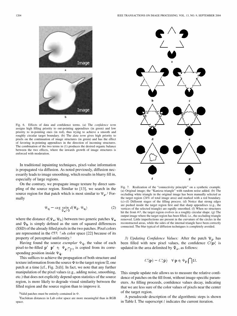
Fig. 6. Effects of data and confidence terms. (a) The confidence termassigns high filling priority to out-pointing appendixes (in green) and lowpriority to in-pointing ones (in red), thus trying to achieve a smooth androughly circular target boundary. (b) The data term gives high priority topixels on the continuation of image structures (in green) and has the effectof favoring in-pointing appendixes in the direction of incoming structures.The combination of the two terms in (1) produces the desired organic balancebetween the two effects, where the inwards growth of image structures isenforced with moderation.
In traditional inpainting techniques, pixel-value informationis propagated via diffusion. As noted previously, diffusion nec-essarily leads to image smoothing, which results in blurry fill in,especially of large regions.
On the contrary, we propagate image texture by direct sam-pling of the source region. Similar to [13], we search in thesource region for that patch which is most similar to .2 For-mally
(2)
where the distance between two generic patchesand is simply defined as the sum of squared differences(SSD) of the already filled pixels in the two patches. Pixel colorsare represented in the color space [22] because of itsproperty of perceptual uniformity.3
Having found the source exemplar , the value of eachpixel-to-be-filled is copied from its corre-sponding position inside .
This suffices to achieve the propagation of both structure andtexture information from the source to the target region , onepatch at a time [cf., Fig. 2(d)]. In fact, we note that any furthermanipulation of the pixel values (e.g., adding noise, smoothing,etc.) that does not explicitly depend upon statistics of the sourceregion, is more likely to degrade visual similarity between thefilled region and the source region than to improve it.
2Valid patches must be entirely contained in �.3Euclidean distances in Lab color space are more meaningful than in RGB
space.
Fig. 7. Realization of the “connectivity principle” on a synthetic example.(a) Original image; the “Kanizsa triangle” with random noise added. (b) Theoccluding white triangle in the original image has been manually selected asthe target region (24% of total image area) and marked with a red boundary.(c)–(f) Different stages of the filling process. (d) Notice that strong edgesare pushed inside the target region first and that sharp appendixes (e.g., thevertices of the selected triangle) are rapidly smoothed. (f) When no structureshit the front �, the target region evolves in a roughly circular shape. (g) Theoutput image where the target region has been filled, i.e., the occluding triangleremoved. Little imperfections are present in the curvature of the circles in thereconstructed areas, while the sides of the internal triangle have been correctlyconnected. The blur typical of diffusion techniques is completely avoided.
3) Updating Confidence Values: After the patch hasbeen filled with new pixel values, the confidence isupdated in the area delimited by , as follows:
This simple update rule allows us to measure the relative confi-dence of patches on the fill front, without image-specific param-eters. As filling proceeds, confidence values decay, indicatingthat we are less sure of the color values of pixels near the centerof the target region.
A pseudocode description of the algorithmic steps is shownin Table I. The superscript indicates the current iteration.
CRIMINISI et al.: REGION FILLING AND OBJECT REMOVAL 1205
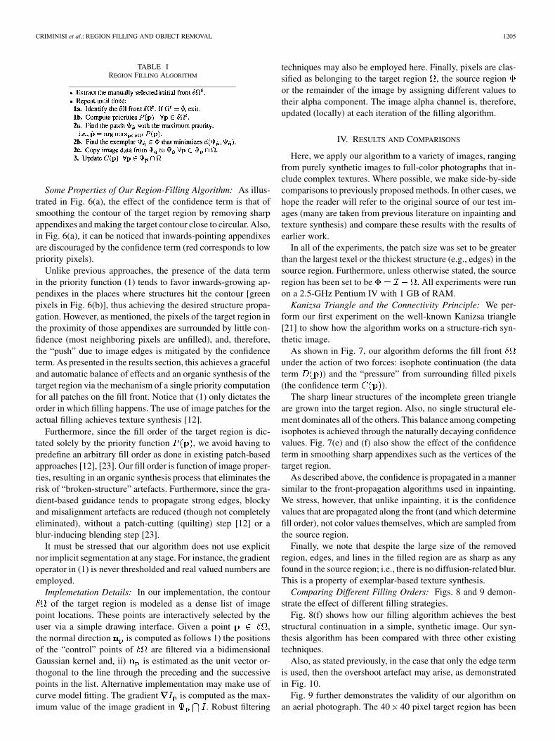
TABLE IREGION FILLING ALGORITHM
Some Properties of Our Region-Filling Algorithm: As illus-trated in Fig. 6(a), the effect of the confidence term is that ofsmoothing the contour of the target region by removing sharpappendixes and making the target contour close to circular. Also,in Fig. 6(a), it can be noticed that inwards-pointing appendixesare discouraged by the confidence term (red corresponds to lowpriority pixels).
Unlike previous approaches, the presence of the data termin the priority function (1) tends to favor inwards-growing ap-pendixes in the places where structures hit the contour [greenpixels in Fig. 6(b)], thus achieving the desired structure propa-gation. However, as mentioned, the pixels of the target region inthe proximity of those appendixes are surrounded by little con-fidence (most neighboring pixels are unfilled), and, therefore,the “push” due to image edges is mitigated by the confidenceterm. As presented in the results section, this achieves a gracefuland automatic balance of effects and an organic synthesis of thetarget region via the mechanism of a single priority computationfor all patches on the fill front. Notice that (1) only dictates theorder in which filling happens. The use of image patches for theactual filling achieves texture synthesis [12].
Furthermore, since the fill order of the target region is dic-tated solely by the priority function , we avoid having topredefine an arbitrary fill order as done in existing patch-basedapproaches [12], [23]. Our fill order is function of image proper-ties, resulting in an organic synthesis process that eliminates therisk of “broken-structure” artefacts. Furthermore, since the gra-dient-based guidance tends to propagate strong edges, blockyand misalignment artefacts are reduced (though not completelyeliminated), without a patch-cutting (quilting) step [12] or ablur-inducing blending step [23].
It must be stressed that our algorithm does not use explicitnor implicit segmentation at any stage. For instance, the gradientoperator in (1) is never thresholded and real valued numbers areemployed.
Implemetation Details: In our implementation, the contourof the target region is modeled as a dense list of image
point locations. These points are interactively selected by theuser via a simple drawing interface. Given a point ,the normal direction is computed as follows 1) the positionsof the “control” points of are filtered via a bidimensionalGaussian kernel and, ii) is estimated as the unit vector or-thogonal to the line through the preceding and the successivepoints in the list. Alternative implementation may make use ofcurve model fitting. The gradient is computed as the max-imum value of the image gradient in . Robust filtering
techniques may also be employed here. Finally, pixels are clas-sified as belonging to the target region , the source regionor the remainder of the image by assigning different values totheir alpha component. The image alpha channel is, therefore,updated (locally) at each iteration of the filling algorithm.
IV. RESULTS AND COMPARISONS
Here, we apply our algorithm to a variety of images, rangingfrom purely synthetic images to full-color photographs that in-clude complex textures. Where possible, we make side-by-sidecomparisons to previously proposed methods. In other cases, wehope the reader will refer to the original source of our test im-ages (many are taken from previous literature on inpainting andtexture synthesis) and compare these results with the results ofearlier work.
In all of the experiments, the patch size was set to be greaterthan the largest texel or the thickest structure (e.g., edges) in thesource region. Furthermore, unless otherwise stated, the sourceregion has been set to be . All experiments were runon a 2.5-GHz Pentium IV with 1 GB of RAM.
Kanizsa Triangle and the Connectivity Principle: We per-form our first experiment on the well-known Kanizsa triangle[21] to show how the algorithm works on a structure-rich syn-thetic image.
As shown in Fig. 7, our algorithm deforms the fill frontunder the action of two forces: isophote continuation (the dataterm ) and the “pressure” from surrounding filled pixels(the confidence term ).
The sharp linear structures of the incomplete green triangleare grown into the target region. Also, no single structural ele-ment dominates all of the others. This balance among competingisophotes is achieved through the naturally decaying confidencevalues. Fig. 7(e) and (f) also show the effect of the confidenceterm in smoothing sharp appendixes such as the vertices of thetarget region.
As described above, the confidence is propagated in a mannersimilar to the front-propagation algorithms used in inpainting.We stress, however, that unlike inpainting, it is the confidencevalues that are propagated along the front (and which determinefill order), not color values themselves, which are sampled fromthe source region.
Finally, we note that despite the large size of the removedregion, edges, and lines in the filled region are as sharp as anyfound in the source region; i.e., there is no diffusion-related blur.This is a property of exemplar-based texture synthesis.
Comparing Different Filling Orders: Figs. 8 and 9 demon-strate the effect of different filling strategies.
Fig. 8(f) shows how our filling algorithm achieves the beststructural continuation in a simple, synthetic image. Our syn-thesis algorithm has been compared with three other existingtechniques.
Also, as stated previously, in the case that only the edge termis used, then the overshoot artefact may arise, as demonstratedin Fig. 10.
Fig. 9 further demonstrates the validity of our algorithm onan aerial photograph. The 40 40 pixel target region has been
1206 IEEE TRANSACTIONS ON IMAGE PROCESSING, VOL. 13, NO. 9, SEPTEMBER 2004
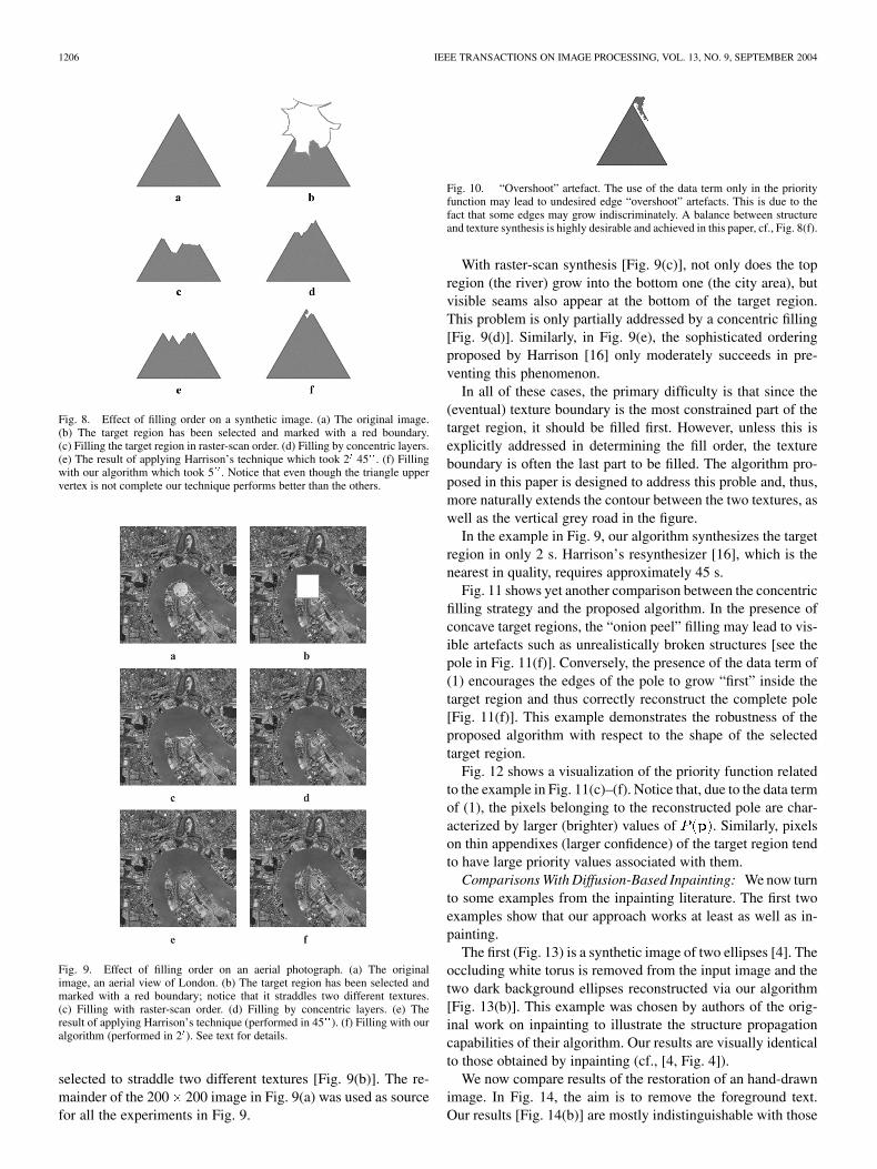
Fig. 8. Effect of filling order on a synthetic image. (a) The original image.(b) The target region has been selected and marked with a red boundary.(c) Filling the target region in raster-scan order. (d) Filling by concentric layers.(e) The result of applying Harrison’s technique which took 2 45 . (f) Fillingwith our algorithm which took 5 . Notice that even though the triangle uppervertex is not complete our technique performs better than the others.
Fig. 9. Effect of filling order on an aerial photograph. (a) The originalimage, an aerial view of London. (b) The target region has been selected andmarked with a red boundary; notice that it straddles two different textures.(c) Filling with raster-scan order. (d) Filling by concentric layers. (e) Theresult of applying Harrison’s technique (performed in 45 ). (f) Filling with ouralgorithm (performed in 2 ). See text for details.
selected to straddle two different textures [Fig. 9(b)]. The re-mainder of the 200 200 image in Fig. 9(a) was used as sourcefor all the experiments in Fig. 9.
Fig. 10. “Overshoot” artefact. The use of the data term only in the priorityfunction may lead to undesired edge “overshoot” artefacts. This is due to thefact that some edges may grow indiscriminately. A balance between structureand texture synthesis is highly desirable and achieved in this paper, cf., Fig. 8(f).
With raster-scan synthesis [Fig. 9(c)], not only does the topregion (the river) grow into the bottom one (the city area), butvisible seams also appear at the bottom of the target region.This problem is only partially addressed by a concentric filling[Fig. 9(d)]. Similarly, in Fig. 9(e), the sophisticated orderingproposed by Harrison [16] only moderately succeeds in pre-venting this phenomenon.
In all of these cases, the primary difficulty is that since the(eventual) texture boundary is the most constrained part of thetarget region, it should be filled first. However, unless this isexplicitly addressed in determining the fill order, the textureboundary is often the last part to be filled. The algorithm pro-posed in this paper is designed to address this proble and, thus,more naturally extends the contour between the two textures, aswell as the vertical grey road in the figure.
In the example in Fig. 9, our algorithm synthesizes the targetregion in only 2 s. Harrison’s resynthesizer [16], which is thenearest in quality, requires approximately 45 s.
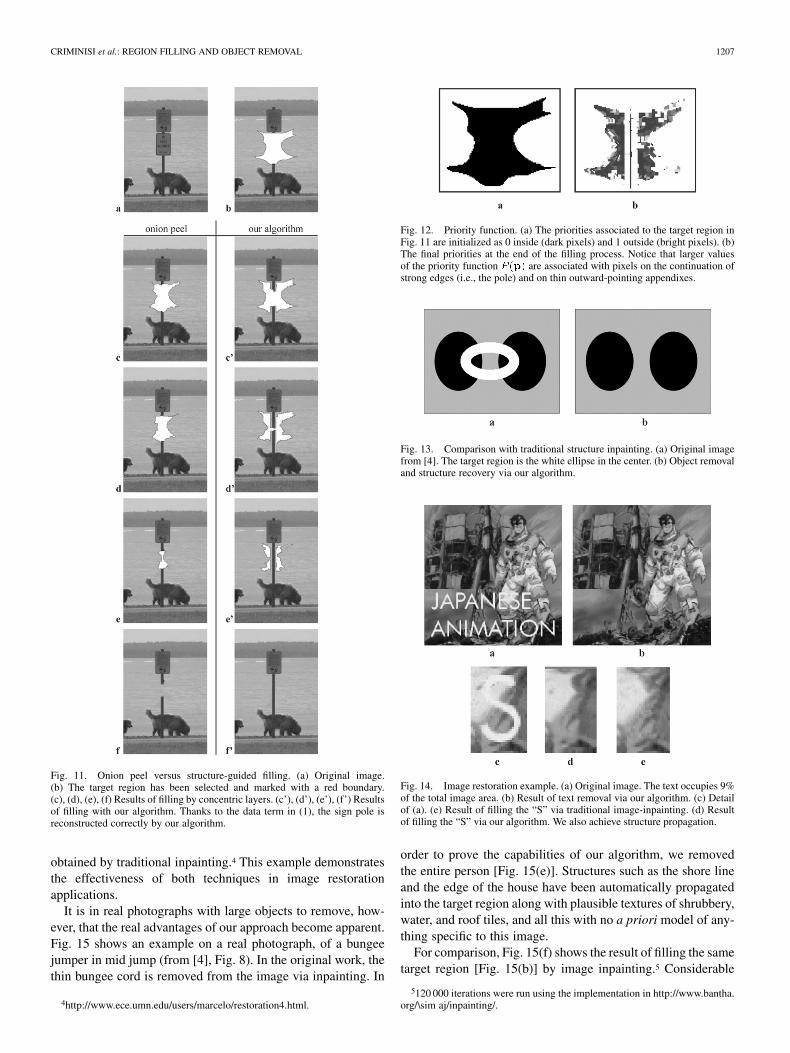
Fig. 11 shows yet another comparison between the concentricfilling strategy and the proposed algorithm. In the presence ofconcave target regions, the “onion peel” filling may lead to vis-ible artefacts such as unrealistically broken structures [see thepole in Fig. 11(f)]. Conversely, the presence of the data term of(1) encourages the edges of the pole to grow “first” inside thetarget region and thus correctly reconstruct the complete pole[Fig. 11(f)]. This example demonstrates the robustness of theproposed algorithm with respect to the shape of the selectedtarget region.
Fig. 12 shows a visualization of the priority function relatedto the example in Fig. 11(c)–(f). Notice that, due to the data termof (1), the pixels belonging to the reconstructed pole are char-acterized by larger (brighter) values of . Similarly, pixelson thin appendixes (larger confidence) of the target region tendto have large priority values associated with them.
Comparisons With Diffusion-Based Inpainting: We now turnto some examples from the inpainting literature. The first twoexamples show that our approach works at least as well as in-painting.
The first (Fig. 13) is a synthetic image of two ellipses [4]. Theoccluding white torus is removed from the input image and thetwo dark background ellipses reconstructed via our algorithm[Fig. 13(b)]. This example was chosen by authors of the orig-inal work on inpainting to illustrate the structure propagationcapabilities of their algorithm. Our results are visually identicalto those obtained by inpainting (cf., [4, Fig. 4]).
We now compare results of the restoration of an hand-drawnimage. In Fig. 14, the aim is to remove the foreground text.Our results [Fig. 14(b)] are mostly indistinguishable with those
CRIMINISI et al.: REGION FILLING AND OBJECT REMOVAL 1207
Fig. 11. Onion peel versus structure-guided filling. (a) Original image.(b) The target region has been selected and marked with a red boundary.(c), (d), (e), (f) Results of filling by concentric layers. (c’), (d’), (e’), (f’) Resultsof filling with our algorithm. Thanks to the data term in (1), the sign pole isreconstructed correctly by our algorithm.
obtained by traditional inpainting.4 This example demonstratesthe effectiveness of both techniques in image restorationapplications.
It is in real photographs with large objects to remove, how-ever, that the real advantages of our approach become apparent.Fig. 15 shows an example on a real photograph, of a bungeejumper in mid jump (from [4], Fig. 8). In the original work, thethin bungee cord is removed from the image via inpainting. In
4http://www.ece.umn.edu/users/marcelo/restoration4.html.
Fig. 12. Priority function. (a) The priorities associated to the target region inFig. 11 are initialized as 0 inside (dark pixels) and 1 outside (bright pixels). (b)The final priorities at the end of the filling process. Notice that larger valuesof the priority function P (p) are associated with pixels on the continuation ofstrong edges (i.e., the pole) and on thin outward-pointing appendixes.
Fig. 13. Comparison with traditional structure inpainting. (a) Original imagefrom [4]. The target region is the white ellipse in the center. (b) Object removaland structure recovery via our algorithm.
Fig. 14. Image restoration example. (a) Original image. The text occupies 9%of the total image area. (b) Result of text removal via our algorithm. (c) Detailof (a). (e) Result of filling the “S” via traditional image-inpainting. (d) Resultof filling the “S” via our algorithm. We also achieve structure propagation.
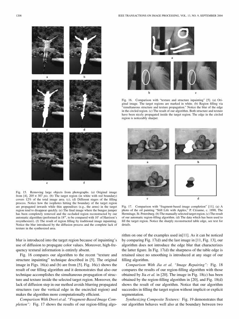
order to prove the capabilities of our algorithm, we removedthe entire person [Fig. 15(e)]. Structures such as the shore lineand the edge of the house have been automatically propagatedinto the target region along with plausible textures of shrubbery,water, and roof tiles, and all this with no a priori model of any-thing specific to this image.
For comparison, Fig. 15(f) shows the result of filling the sametarget region [Fig. 15(b)] by image inpainting.5 Considerable
5120 000 iterations were run using the implementation in http://www.bantha.org/\sim aj/inpainting/.
1208 IEEE TRANSACTIONS ON IMAGE PROCESSING, VOL. 13, NO. 9, SEPTEMBER 2004
Fig. 15. Removing large objects from photographs. (a) Original imagefrom [4], 205� 307 pix. (b) The target region (in white with red boundary)covers 12% of the total image area. (c), (d) Different stages of the fillingprocess. Notice how the isophotes hitting the boundary of the target regionare propagated inwards while thin appendixes (e.g., the arms) in the targetregion tend to disappear quickly. (e) The final image where the bungee jumperhas been completely removed and the occluded region reconstructed by ourautomatic algorithm (performed in 18 , to be compared with 10 of Harrison’sresynthesizer). (f) The result of region filling by traditional image inpainting.Notice the blur introduced by the diffusion process and the complete lack oftexture in the synthesized area.
blur is introduced into the target region because of inpainting’suse of diffusion to propagate color values. Moreover, high-fre-quency textural information is entirely absent.
Fig. 16 compares our algorithm to the recent “texture andstructure inpainting” technique described in [5]. The originalimage in Figs. 16(a) and (b) are from [5]. Fig. 16(c) shows theresult of our filling algorithm and it demonstrates that also ourtechnique accomplishes the simultaneous propagation of struc-ture and texture inside the selected target region. Moreover, thelack of diffusion step in our method avoids blurring propagatedstructures (see the vertical edge in the encircled region) andmakes the algorithm more computationally efficient.
Comparison With Drori et al. “Fragment-Based Image Com-pletion”: Fig. 17 shows the results of our region-filling algo-
Fig. 16. Comparison with “texture and structure inpainting” [5]. (a) Ori-ginal image. The target regions are marked in white. (b) Region filling via“simultaneous structure and texture propagation.” Notice the blur of the edgein the circled region. (c) The result of our algorithm. Both structure and texturehave been nicely propagated inside the target region. The edge in the circledregion is noticeably sharper.
Fig. 17. Comparison with “fragment-based image completion” [11]. (a) Aphoto of the oil painting “Still Life with Apples,” P. Cézanne, c. 1890, TheHermitage, St. Petersburg. (b) The manually selected target region. (c) The resultof our automatic region-filling algorithm. (d) The data which has been used tofill the target region. Notice the sharply reconstructed table edge, see text fordetails.
rithm on one of the examples used in[11]. As it can be noticedby comparing Fig. 17(d) and the last image in [11, Fig. 13], ouralgorithm does not introduce the edge blur that characterizesthe latter figure. In Fig. 17(d) the sharpness of the table edge isretained since no smoothing is introduced at any stage of ourfilling algorithm.
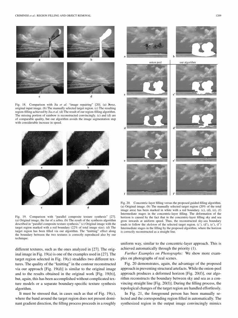
Comparison With Jia et al. “Image Repairing”: Fig. 18compares the results of our region-filling algorithm with thoseobtained by Jia et al. in [20]. The image in Fig. 18(c) has beenobtained by the region-filling algorithm in [20], and Fig. 18(d)shows the result of our algorithm. Notice that our algorithmsucceedes in filling the target region without implicit or explicitsegmentation.
Synthesizing Composite Textures: Fig. 19 demonstrates thatour algorithm behaves well also at the boundary between two
CRIMINISI et al.: REGION FILLING AND OBJECT REMOVAL 1209
Fig. 18. Comparison with Jia et al. “image repairing” [20]. (a) Moor,original input image. (b) The manually selected target region. (c) The resultingregion-filling achieved by Jia et al. (d) The result of our region-filling algorithm.The missing portion of rainbow is reconstructed convincingly. (c) and (d) areof comparable quality, but our algorithm avoids the image segmentation stepwith considerable increase in speed.
Fig. 19. Comparison with “parallel composite texture synthesis” [27].(a) Original image, the fur of a zebra. (b) The result of the synthesis algorithmdescribed in “parallel composite texture synthesis.” (c) Original image with thetarget region marked with a red boundary (22% of total image size). (d) Thetarget region has been filled via our algorithm. The “knitting” effect alongthe boundary between the two textures is correctly reproduced also by ourtechnique.
different textures, such as the ones analyzed in [27]. The orig-inal image in Fig. 19(a) is one of the examples used in [27]. Thetarget region selected in Fig. 19(c) straddles two different tex-tures. The quality of the “knitting” in the contour reconstructedvia our approach [Fig. 19(d)] is similar to the original imageand to the results obtained in the original work [Fig. 19(b)],but, again, this has been accomplished without complicated tex-ture models or a separate boundary-specific texture synthesisalgorithm.
It must be stressed that, in cases such as that of Fig. 19(c),where the band around the target region does not present domi-nant gradient direction, the filling process proceeds in a roughly
Fig. 20. Concentric-layer filling versus the proposed guided filling algorithm.(a) Original image. (b) The manually selected target region (20% of the totalimage area) has been marked in white with a red boundary. (c), (d), (e), (f)Intermediate stages in the concentric-layer filling. The deformation of thehorizon is caused by the fact that in the concentric-layer filling sky and seagrow inwards at uniform speed. Thus, the reconstructed sky-sea boundarytends to follow the skeleton of the selected target region. (c’), (d’), (e’), (f’)Intermediate stages in the filling by the proposed algorithm, where the horizonis correctly reconstructed as a straight line.
uniform way, similar to the concentric-layer approach. This isachieved automatically through the priority (1).
Further Examples on Photographs: We show more exam-ples on photographs of real scenes.
Fig. 20 demonstrates, again, the advantage of the proposedapproach in preventing structural artefacts. While the onion-peelapproach produces a deformed horizon [Fig. 20(f)], our algo-rithm reconstructs the boundary between sky and sea as a con-vincing straight line [Fig. 20(f)]. During the filling process, thetopological changes of the target region are handled effortlessly.
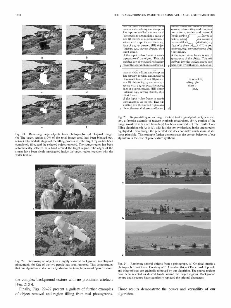
In Fig. 21, the foreground person has been manually se-lected and the corresponding region filled in automatically. Thesynthesized region in the output image convincingly mimics
1210 IEEE TRANSACTIONS ON IMAGE PROCESSING, VOL. 13, NO. 9, SEPTEMBER 2004
Fig. 21. Removing large objects from photographs. (a) Original image.(b) The target region (10% of the total image area) has been blanked out.(c)–(e) Intermediate stages of the filling process. (f) The target region has beencompletely filled and the selected object removed. The source region has beenautomatically selected as a band around the target region. The edges of thestones have been nicely propagated inside the target region together with thewater texture.
Fig. 22. Removing an object on a highly textured background. (a) Originalphotograph. (b) One of the two people has been removed. This demonstratesthat our algorithm works correctly also for the (simpler) case of “pure” texture.
the complex background texture with no prominent artefacts[Fig. 21(f)].
Finally, Figs. 22–27 present a gallery of further examplesof object removal and region filling from real photographs.
Fig. 23. Region-filling on an image of a text. (a) Original photo of typewrittentext, a favorite example of texture synthesis researchers. (b) A portion of theimage (marked with a red boundary) has been removed. (c) The result of ourfilling algorithm. (d) As in (c), with just the text synthesized in the target regionhighlighted. Even though the generated text does not make much sense, it stilllooks plausible. This example further demonstrates the correct behavior of ouralgorithm in the case of pure texture synthesis.
Fig. 24. Removing several objects from a photograph. (a) Original image; aphotograph from Ghana, Courtesy of P. Anandan. (b), (c) The crowd of peopleand other objects are gradually removed by our algorithm. The source regionshave been selected as dilated bands around the target regions. Backgroundtexture and structure have seamlessly replaced the original characters.
Those results demonstrate the power and versatility of ouralgorithm.
CRIMINISI et al.: REGION FILLING AND OBJECT REMOVAL 1211
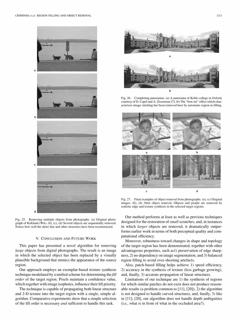
Fig. 25. Removing multiple objects from photographs. (a) Original photo-graph of Kirkland (WA). (b), (c), (d) Several objects are sequentially removed.Notice how well the shore line and other structures have been reconstructed.
V. CONCLUSION AND FUTURE WORK
This paper has presented a novel algorithm for removinglarge objects from digital photographs. The result is an imagein which the selected object has been replaced by a visuallyplausible background that mimics the appearance of the sourceregion.
Our approach employs an exemplar-based texture synthesistechnique modulated by a unified scheme for determining the fillorder of the target region. Pixels maintain a confidence value,which together with image isophotes, influence their fill priority.
The technique is capable of propagating both linear structureand 2-D texture into the target region with a single, simple al-gorithm. Comparative experiments show that a simple selectionof the fill order is necessary and sufficient to handle this task.
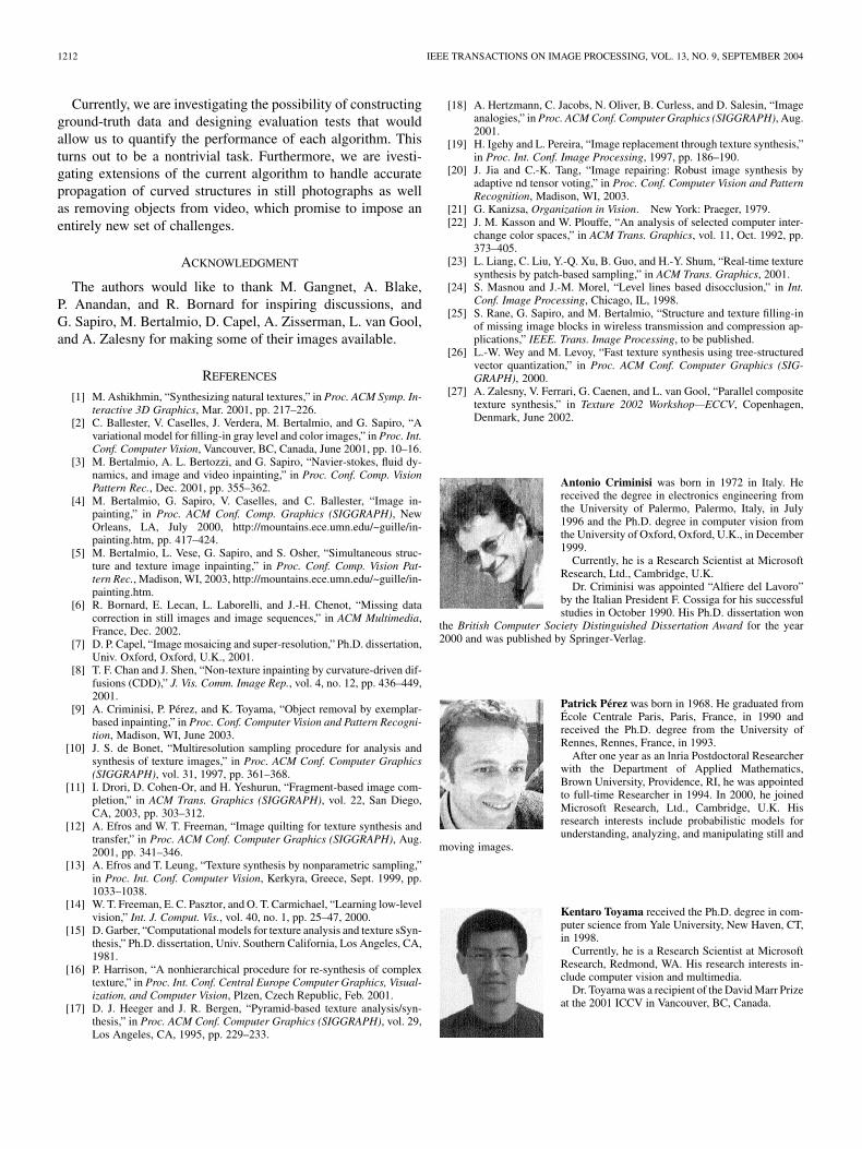
Fig. 26. Completing panoramas. (a) A panorama of Keble college in Oxford,courtesy of D. Capel and A. Zisserman [7]. (b) The “bow-tie” effect which char-acterizes image stitching has been removed here by automatic region in filling.
Fig. 27. Final examples of object removal from photographs. (a), (c) Originalimages. (b), (d) After object removal. Objects and people are removed byrealistic edge and texture synthesis in the selected target regions.
Our method performs at least as well as previous techniquesdesigned for the restoration of small scratches, and, in instancesin which larger objects are removed, it dramatically outper-forms earlier work in terms of both perceptual quality and com-putational efficiency.
Moreover, robustness toward changes in shape and topologyof the target region has been demonstrated, together with otheradvantageous properties, such as1) preservation of edge sharp-ness, 2) no dependency on image segmentation, and 3) balancedregion filling to avoid over-shooting artefacts.
Also, patch-based filling helps achieve 1) speed efficiency,2) accuracy in the synthesis of texture (less garbage growing),and, finally, 3) accurate propagation of linear structures.
Limitations of our technique are 1) the synthesis of regionsfor which similar patches do not exist does not produce reason-able results (a problem common to [11], [20]), 2) the algorithmis not designed to handle curved structures, and, finally, 3) likein [11], [20], our algorithm does not handle depth ambiguities(i.e., what is in front of what in the occluded area?).
1212 IEEE TRANSACTIONS ON IMAGE PROCESSING, VOL. 13, NO. 9, SEPTEMBER 2004
Currently, we are investigating the possibility of constructingground-truth data and designing evaluation tests that wouldallow us to quantify the performance of each algorithm. Thisturns out to be a nontrivial task. Furthermore, we are ivesti-gating extensions of the current algorithm to handle accuratepropagation of curved structures in still photographs as wellas removing objects from video, which promise to impose anentirely new set of challenges.
ACKNOWLEDGMENT
The authors would like to thank M. Gangnet, A. Blake,P. Anandan, and R. Bornard for inspiring discussions, andG. Sapiro, M. Bertalmio, D. Capel, A. Zisserman, L. van Gool,and A. Zalesny for making some of their images available.
REFERENCES
[1] M. Ashikhmin, “Synthesizing natural textures,” in Proc. ACM Symp. In-teractive 3D Graphics, Mar. 2001, pp. 217–226.
[2] C. Ballester, V. Caselles, J. Verdera, M. Bertalmio, and G. Sapiro, “Avariational model for filling-in gray level and color images,” in Proc. Int.Conf. Computer Vision, Vancouver, BC, Canada, June 2001, pp. 10–16.
[3] M. Bertalmio, A. L. Bertozzi, and G. Sapiro, “Navier-stokes, fluid dy-namics, and image and video inpainting,” in Proc. Conf. Comp. VisionPattern Rec., Dec. 2001, pp. 355–362.
[4] M. Bertalmio, G. Sapiro, V. Caselles, and C. Ballester, “Image in-painting,” in Proc. ACM Conf. Comp. Graphics (SIGGRAPH), NewOrleans, LA, July 2000, http://mountains.ece.umn.edu/~guille/in-painting.htm, pp. 417–424.
[5] M. Bertalmio, L. Vese, G. Sapiro, and S. Osher, “Simultaneous struc-ture and texture image inpainting,” in Proc. Conf. Comp. Vision Pat-tern Rec., Madison, WI, 2003, http://mountains.ece.umn.edu/~guille/in-painting.htm.
[6] R. Bornard, E. Lecan, L. Laborelli, and J.-H. Chenot, “Missing datacorrection in still images and image sequences,” in ACM Multimedia,France, Dec. 2002.
[7] D. P. Capel, “Image mosaicing and super-resolution,” Ph.D. dissertation,Univ. Oxford, Oxford, U.K., 2001.
[8] T. F. Chan and J. Shen, “Non-texture inpainting by curvature-driven dif-fusions (CDD),” J. Vis. Comm. Image Rep., vol. 4, no. 12, pp. 436–449,2001.
[9] A. Criminisi, P. Pérez, and K. Toyama, “Object removal by exemplar-based inpainting,” in Proc. Conf. Computer Vision and Pattern Recogni-tion, Madison, WI, June 2003.
[10] J. S. de Bonet, “Multiresolution sampling procedure for analysis andsynthesis of texture images,” in Proc. ACM Conf. Computer Graphics(SIGGRAPH), vol. 31, 1997, pp. 361–368.
[11] I. Drori, D. Cohen-Or, and H. Yeshurun, “Fragment-based image com-pletion,” in ACM Trans. Graphics (SIGGRAPH), vol. 22, San Diego,CA, 2003, pp. 303–312.
[12] A. Efros and W. T. Freeman, “Image quilting for texture synthesis andtransfer,” in Proc. ACM Conf. Computer Graphics (SIGGRAPH), Aug.2001, pp. 341–346.
[13] A. Efros and T. Leung, “Texture synthesis by nonparametric sampling,”in Proc. Int. Conf. Computer Vision, Kerkyra, Greece, Sept. 1999, pp.1033–1038.
[14] W. T. Freeman, E. C. Pasztor, and O. T. Carmichael, “Learning low-levelvision,” Int. J. Comput. Vis., vol. 40, no. 1, pp. 25–47, 2000.
[15] D. Garber, “Computational models for texture analysis and texture sSyn-thesis,” Ph.D. dissertation, Univ. Southern California, Los Angeles, CA,1981.
[16] P. Harrison, “A nonhierarchical procedure for re-synthesis of complextexture,” in Proc. Int. Conf. Central Europe Computer Graphics, Visual-ization, and Computer Vision, Plzen, Czech Republic, Feb. 2001.
[17] D. J. Heeger and J. R. Bergen, “Pyramid-based texture analysis/syn-thesis,” in Proc. ACM Conf. Computer Graphics (SIGGRAPH), vol. 29,Los Angeles, CA, 1995, pp. 229–233.
[18] A. Hertzmann, C. Jacobs, N. Oliver, B. Curless, and D. Salesin, “Imageanalogies,” in Proc. ACM Conf. Computer Graphics (SIGGRAPH), Aug.2001.
[19] H. Igehy and L. Pereira, “Image replacement through texture synthesis,”in Proc. Int. Conf. Image Processing, 1997, pp. 186–190.
[20] J. Jia and C.-K. Tang, “Image repairing: Robust image synthesis byadaptive nd tensor voting,” in Proc. Conf. Computer Vision and PatternRecognition, Madison, WI, 2003.
[21] G. Kanizsa, Organization in Vision. New York: Praeger, 1979.[22] J. M. Kasson and W. Plouffe, “An analysis of selected computer inter-
change color spaces,” in ACM Trans. Graphics, vol. 11, Oct. 1992, pp.373–405.
[23] L. Liang, C. Liu, Y.-Q. Xu, B. Guo, and H.-Y. Shum, “Real-time texturesynthesis by patch-based sampling,” in ACM Trans. Graphics, 2001.
[24] S. Masnou and J.-M. Morel, “Level lines based disocclusion,” in Int.Conf. Image Processing, Chicago, IL, 1998.
[25] S. Rane, G. Sapiro, and M. Bertalmio, “Structure and texture filling-inof missing image blocks in wireless transmission and compression ap-plications,” IEEE. Trans. Image Processing, to be published.
[26] L.-W. Wey and M. Levoy, “Fast texture synthesis using tree-structuredvector quantization,” in Proc. ACM Conf. Computer Graphics (SIG-GRAPH), 2000.
[27] A. Zalesny, V. Ferrari, G. Caenen, and L. van Gool, “Parallel compositetexture synthesis,” in Texture 2002 Workshop—ECCV, Copenhagen,Denmark, June 2002.
Antonio Criminisi was born in 1972 in Italy. Hereceived the degree in electronics engineering fromthe University of Palermo, Palermo, Italy, in July1996 and the Ph.D. degree in computer vision fromthe University of Oxford, Oxford, U.K., in December1999.
Currently, he is a Research Scientist at MicrosoftResearch, Ltd., Cambridge, U.K.
Dr. Criminisi was appointed “Alfiere del Lavoro”by the Italian President F. Cossiga for his successfulstudies in October 1990. His Ph.D. dissertation won
the British Computer Society Distinguished Dissertation Award for the year2000 and was published by Springer-Verlag.
Patrick Pérez was born in 1968. He graduated fromÉcole Centrale Paris, Paris, France, in 1990 andreceived the Ph.D. degree from the University ofRennes, Rennes, France, in 1993.
After one year as an lnria Postdoctoral Researcherwith the Department of Applied Mathematics,Brown University, Providence, RI, he was appointedto full-time Researcher in 1994. In 2000, he joinedMicrosoft Research, Ltd., Cambridge, U.K. Hisresearch interests include probabilistic models forunderstanding, analyzing, and manipulating still and
moving images.
Kentaro Toyama received the Ph.D. degree in com-puter science from Yale University, New Haven, CT,in 1998.
Currently, he is a Research Scientist at MicrosoftResearch, Redmond, WA. His research interests in-clude computer vision and multimedia.
Dr. Toyama was a recipient of the David Marr Prizeat the 2001 ICCV in Vancouver, BC, Canada.