Embed Size (px)
Citation preview

The Chamberlain Group, Inc.845 Larch AvenueElmhurst, Illinois 60126-1196www.liftmaster.com
12 VOLT DC SINGLE SOLAR RESIDENTIAL GATE OPERATOR
Models LA412 and LA412-S
For Residential Use Only
Owner’s Manual
■ Please read this manual and the enclosed safety materials carefully!
■ Periodic checks of the operator by a qualified technician are required to ensure safe operation.
■ The model number label is located inside the control box of your operator.
■■ Serial #
■■ Installation Date
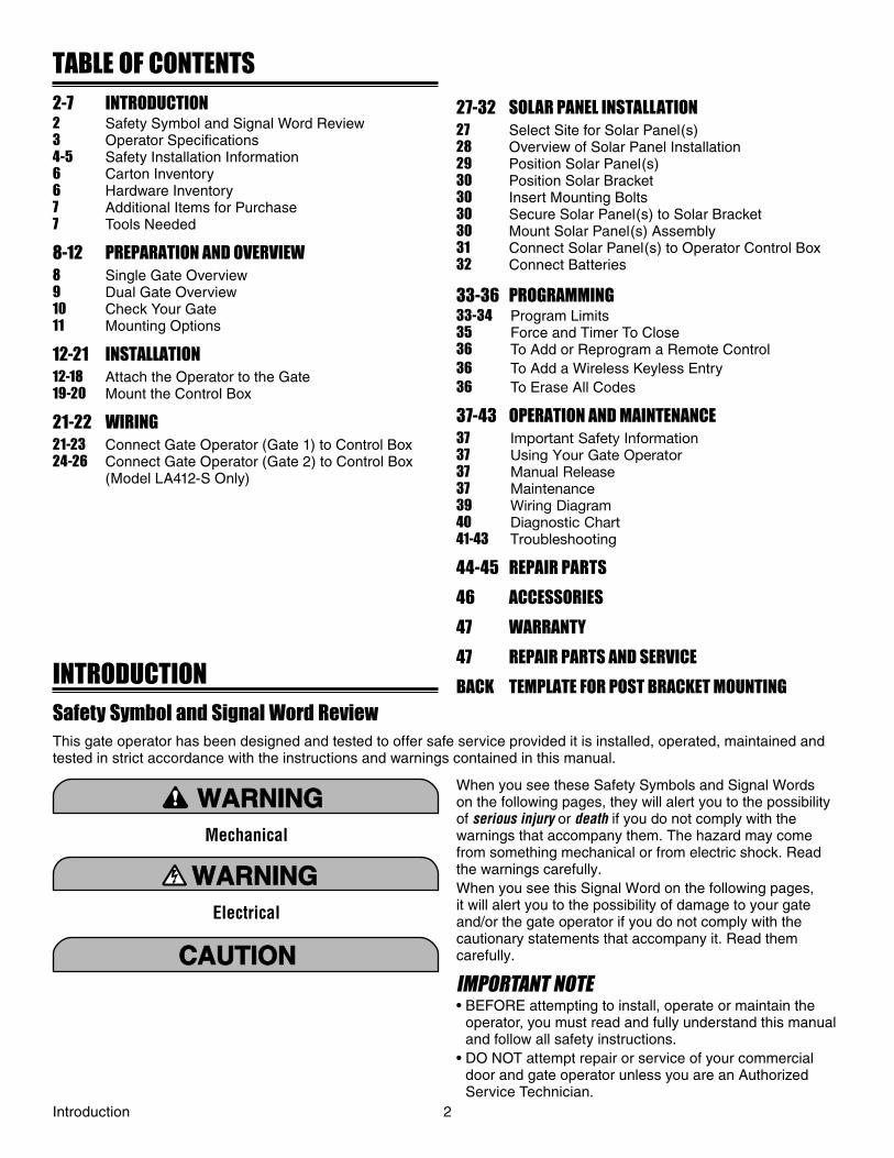
TABLE OF CONTENTS2-7 INTRODUCTION2 Safety Symbol and Signal Word Review3 Operator Specifi cations4-5 Safety Installation Information6 Carton Inventory6 Hardware Inventory7 Additional Items for Purchase7 Tools Needed
8-12 PREPARATION AND OVERVIEW8 Single Gate Overview9 Dual Gate Overview10 Check Your Gate11 Mounting Options
12-21 INSTALLATION12-18 Attach the Operator to the Gate19-20 Mount the Control Box
21-22 WIRING21-23 Connect Gate Operator (Gate 1) to Control Box24-26 Connect Gate Operator (Gate 2) to Control Box (Model LA412-S Only)
27-32 SOLAR PANEL INSTALLATION27 Select Site for Solar Panel(s)28 Overview of Solar Panel Installation29 Position Solar Panel(s)30 Position Solar Bracket30 Insert Mounting Bolts30 Secure Solar Panel(s) to Solar Bracket30 Mount Solar Panel(s) Assembly31 Connect Solar Panel(s) to Operator Control Box32 Connect Batteries
33-36 PROGRAMMING33-34 Program Limits35 Force and Timer To Close36 To Add or Reprogram a Remote Control36 To Add a Wireless Keyless Entry36 To Erase All Codes
37-43 OPERATION AND MAINTENANCE37 Important Safety Information37 Using Your Gate Operator37 Manual Release37 Maintenance39 Wiring Diagram40 Diagnostic Chart41-43 Troubleshooting
44-45 REPAIR PARTS
46 ACCESSORIES
47 WARRANTY
47 REPAIR PARTS AND SERVICE
BACK TEMPLATE FOR POST BRACKET MOUNTINGINTRODUCTIONSafety Symbol and Signal Word ReviewThis gate operator has been designed and tested to offer safe service provided it is installed, operated, maintained and tested in strict accordance with the instructions and warnings contained in this manual.
Mechanical
Electrical
ATTENTION
AVERTISSEMENT AVERTISSEMENT
AVERTISSEMENT
WARNINGWARNING
CAUTION
WARNING
WARNING
PRECAUCIÓN ADVERTENCIA
ADVERTENCIAADVERTENCIA
ATTENTION
AVERTISSEMENT AVERTISSEMENT
AVERTISSEMENT
WARNING
CAUTIONCAUTION
WARNING
WARNING
PRECAUCIÓN ADVERTENCIA
ADVERTENCIAADVERTENCIA
ATTENTION
AVERTISSEMENT AVERTISSEMENT
AVERTISSEMENT
WARNING
CAUTION
WARNINGWARNING
WARNING
PRECAUCIÓN ADVERTENCIA
ADVERTENCIAADVERTENCIA
When you see these Safety Symbols and Signal Words on the following pages, they will alert you to the possibility of serious injury or death if you do not comply with the warnings that accompany them. The hazard may come from something mechanical or from electric shock. Read the warnings carefully.When you see this Signal Word on the following pages, it will alert you to the possibility of damage to your gate and/or the gate operator if you do not comply with the cautionary statements that accompany it. Read them carefully.
IMPORTANT NOTE• BEFORE attempting to install, operate or maintain the
operator, you must read and fully understand this manual and follow all safety instructions.
• DO NOT attempt repair or service of your commercial door and gate operator unless you are an Authorized Service Technician.
Introduction 2
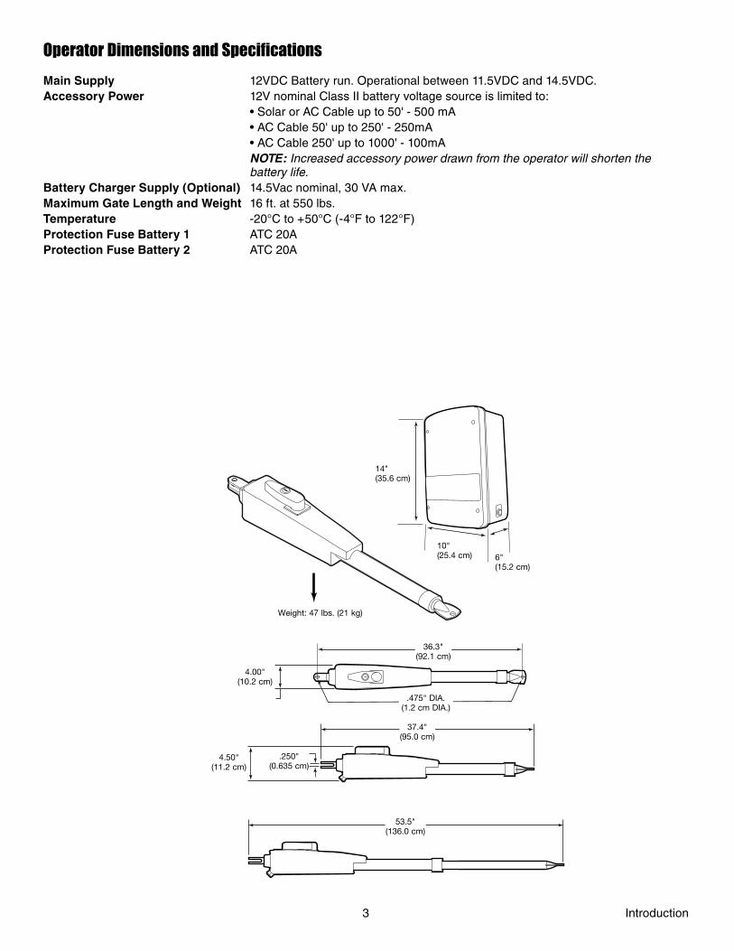
Operator Dimensions and Specifications
Main Supply 12VDC Battery run. Operational between 11.5VDC and 14.5VDC.Accessory Power 12V nominal Class II battery voltage source is limited to: • Solar or AC Cable up to 50' - 500 mA • AC Cable 50' up to 250' - 250mA • AC Cable 250' up to 1000' - 100mA NOTE: Increased accessory power drawn from the operator will shorten the battery life.Battery Charger Supply (Optional) 14.5Vac nominal, 30 VA max.Maximum Gate Length and Weight 16 ft. at 550 lbs. Temperature -20°C to +50°C (-4°F to 122°F)Protection Fuse Battery 1 ATC 20AProtection Fuse Battery 2 ATC 20A
Weight: 47 lbs. (21 kg)
10"(25.4 cm)
14"(35.6 cm)
6"(15.2 cm)
36.3"(92.1 cm)
.475" DIA.(1.2 cm DIA.)
4.50"(11.2 cm)
.250"(0.635 cm)
37.4"(95.0 cm)
53.5"(136.0 cm)
4.00"(10.2 cm)
3 Introduction
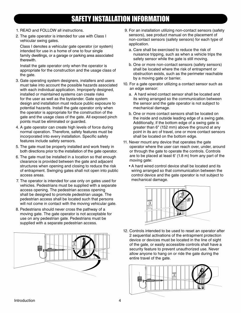
1. READ and FOLLOW all instructions.
2. The gate operator is intended for use with Class I vehicular swing gates.
Class I denotes a vehicular gate operator (or system) intended for use in a home of one to four single family dwellings, or a garage or parking area associated therewith.
Install the gate operator only when the operator is appropriate for the construction and the usage class of the gate.
3. Gate operating system designers, installers and users must take into account the possible hazards associated with each individual application. Improperly designed, installed or maintained systems can create risks for the user as well as the bystander. Gate system design and installation must reduce public exposure to potential hazards. Install the gate operator only when the operator is appropriate for the construction of the gate and the usage class of the gate. All exposed pinch points must be eliminated or guarded.
4. A gate operator can create high levels of force during normal operation. Therefore, safety features must be incorporated into every installation. Specifi c safety features include safety sensors.
5. The gate must be properly installed and work freely in both directions prior to the installation of the gate operator.
6. The gate must be installed in a location so that enough clearance is provided between the gate and adjacent structures when opening and closing to reduce the risk of entrapment. Swinging gates shall not open into public access areas.
7. The operator is intended for use only on gates used for vehicles. Pedestrians must be supplied with a separate access opening. The pedestrian access opening shall be designed to promote pedestrian usage. The pedestrian access shall be located such that persons will not come in contact with the moving vehicular gate.
8. Pedestrians should never cross the pathway of a moving gate. The gate operator is not acceptable for use on any pedestrian gate. Pedestrians must be supplied with a separate pedestrian access.
9. For an installation utilizing non-contact sensors (safety sensors), see product manual on the placement of non-contact sensors (safety sensors) for each type of application.
a. Care shall be exercised to reduce the risk of nuisance tripping, such as when a vehicle trips the safety sensor while the gate is still moving.
b. One or more non-contact sensors (safety sensors) shall be located where the risk of entrapment or obstruction exists, such as the perimeter reachable by a moving gate or barrier.
10. For a gate operator utilizing a contact sensor such as an edge sensor:
a. A hard wired contact sensor shall be located and its wiring arranged so the communication between the sensor and the gate operator is not subject to mechanical damage.
b. One or more contact sensors shall be located on the inside and outside leading edge of a swing gate. Additionally, if the bottom edge of a swing gate is greater than 6" (152 mm) above the ground at any point in its arc of travel, one or more contact sensors shall be located on the bottom edge.
11. Never mount any device that operates the gate operator where the user can reach over, under, around or through the gate to operate the controls. Controls are to be placed at least 6' (1.8 m) from any part of the moving gate:
• A hard wired control device shall be located and its wiring arranged so that communication between the control device and the gate operator is not subject to mechanical damage.
12. Controls intended to be used to reset an operator after 2 sequential activations of the entrapment protection device or devices must be located in the line of sight of the gate, or easily accessible controls shall have a security feature to prevent unauthorized use. Never allow anyone to hang on or ride the gate during the entire travel of the gate.
Introduction 4
SAFETY INSTALLATION INFORMATION
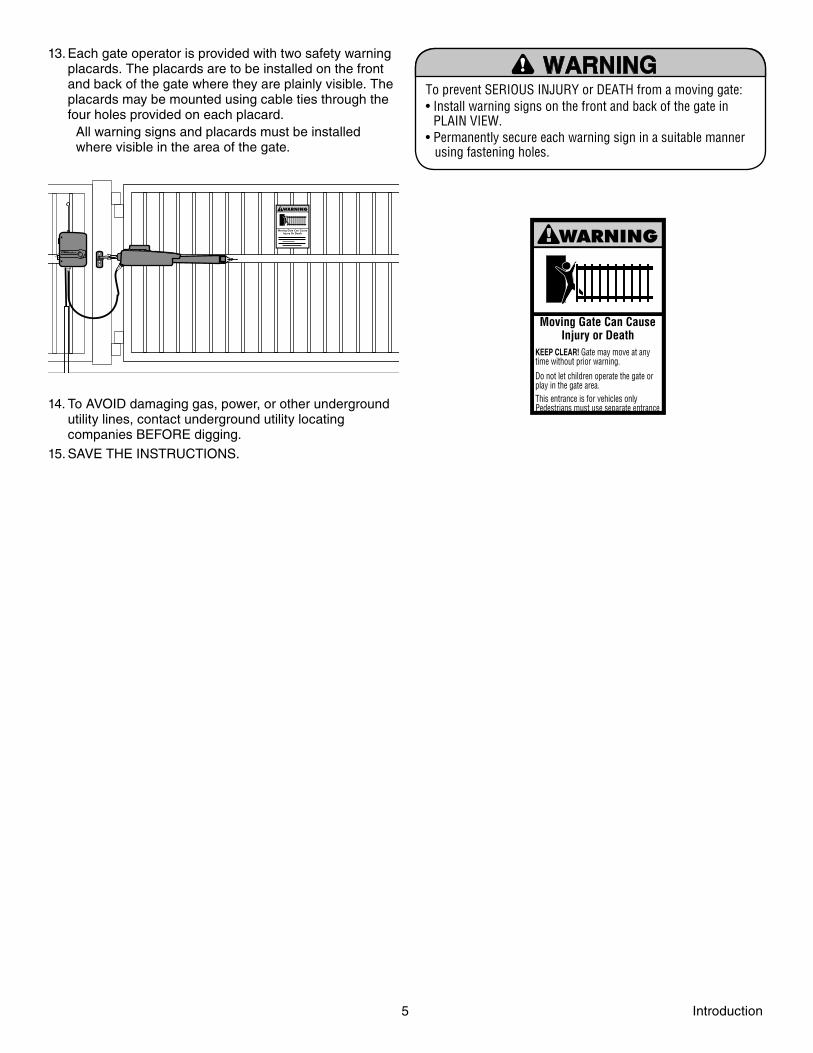
13. Each gate operator is provided with two safety warning placards. The placards are to be installed on the front and back of the gate where they are plainly visible. The placards may be mounted using cable ties through the four holes provided on each placard.
All warning signs and placards must be installed where visible in the area of the gate.
14. To AVOID damaging gas, power, or other underground utility lines, contact underground utility locating companies BEFORE digging.
15. SAVE THE INSTRUCTIONS.
To prevent SERIOUS INJURY or DEATH from a moving gate:• Install warning signs on the front and back of the gate in
PLAIN VIEW.• Permanently secure each warning sign in a suitable manner
using fastening holes.
Moving Gate Can CauseInjury or Death
KEEP CLEAR! Gate may move at anytime without prior warning.
Do not let children operate the gate orplay in the gate area.This entrance is for vehicles only.Pedestrians must use separate entrance
5 Introduction
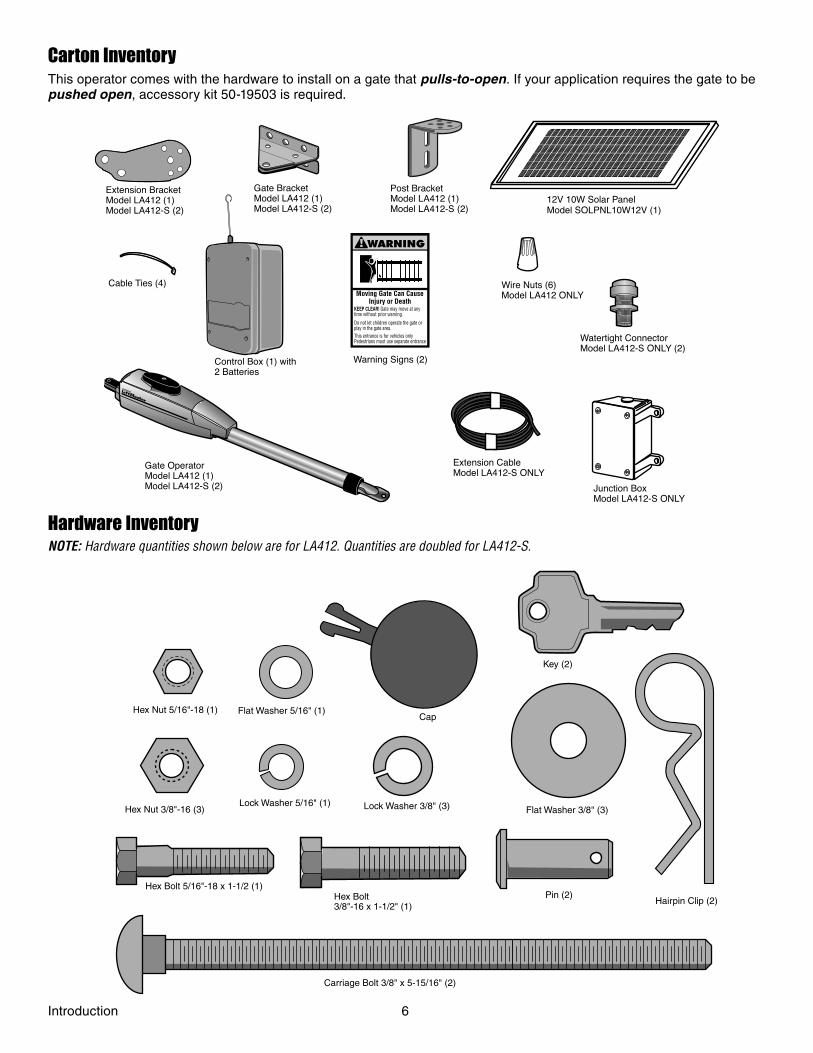
Carton InventoryThis operator comes with the hardware to install on a gate that pulls-to-open. If your application requires the gate to be pushed open, accessory kit 50-19503 is required.
Warning Signs (2)
Moving Gate Can Cause Injury or Death
KEEP CLEAR! Gate may move at any time without prior warning. Do not let children operate the gate or play in the gate area. This entrance is for vehicles only Pedestrians must use separate entrance
Post BracketModel LA412 (1)Model LA412-S (2)
Gate OperatorModel LA412 (1)Model LA412-S (2) Junction Box
Model LA412-S ONLY
Gate BracketModel LA412 (1)Model LA412-S (2)
Wire Nuts (6)Model LA412 ONLY
Control Box (1) with2 Batteries
Extension BracketModel LA412 (1)Model LA412-S (2)
Watertight ConnectorModel LA412-S ONLY (2)
Cable Ties (4)
Extension CableModel LA412-S ONLY
12V 10W Solar PanelModel SOLPNL10W12V (1)
Hardware InventoryNOTE: Hardware quantities shown below are for LA412. Quantities are doubled for LA412-S.
Flat Washer 3/8" (3)Hex Nut 3/8"-16 (3) Lock Washer 3/8" (3)
Hex Bolt 5/16"-18 x 1-1/2 (1)
Carriage Bolt 3/8" x 5-15/16" (2)
Hex Bolt3/8"-16 x 1-1/2" (1)
Hex Nut 5/16"-18 (1)
Hairpin Clip (2)
Flat Washer 5/16" (1)
Lock Washer 5/16" (1)
Pin (2)
Cap
Key (2)
Introduction 6
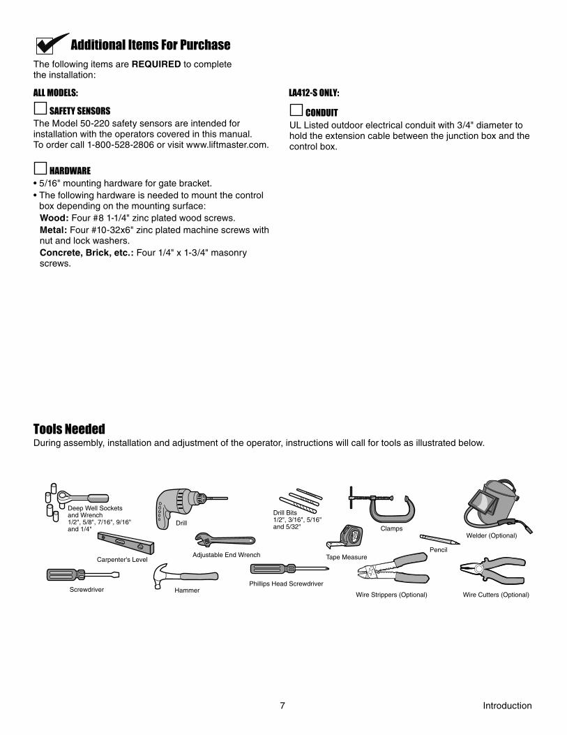
Additional Items For PurchaseThe following items are REQUIRED to completethe installation:
SAFETY SENSORSThe Model 50-220 safety sensors are intended for installation with the operators covered in this manual.To order call 1-800-528-2806 or visit www.liftmaster.com.
HARDWARE• 5/16" mounting hardware for gate bracket.• The following hardware is needed to mount the control
box depending on the mounting surface: Wood: Four #8 1-1/4" zinc plated wood screws. Metal: Four #10-32x6" zinc plated machine screws with
nut and lock washers. Concrete, Brick, etc.: Four 1/4" x 1-3/4" masonry
screws.
CONDUITUL Listed outdoor electrical conduit with 3/4" diameter to hold the extension cable between the junction box and the control box.
Tools NeededDuring assembly, installation and adjustment of the operator, instructions will call for tools as illustrated below.
Screwdriver
Adjustable End Wrench Tape Measure
2 1
Pencil
Carpenter's Level
Clamps
Phillips Head Screwdriver
Deep Well Sockets and Wrench1/2", 5/8", 7/16", 9/16" and 1/4"
Hammer
Drill
Drill Bits 1/2", 3/16", 5/16" and 5/32"
Wire Cutters (Optional) Wire Strippers (Optional)
Welder (Optional)
7 Introduction
ALL MODELS: LA412-S ONLY:
Moving Gate Can Cause
Injury or Death
KEEP CLEAR! Gate may move at any
time without prior warning.
Do not let children operate the gate or
play in the gate area.
This entrance is for vehicles only
Pedestrians must use separate entrance
12 gaugewire
8 ft.(2.4 m)
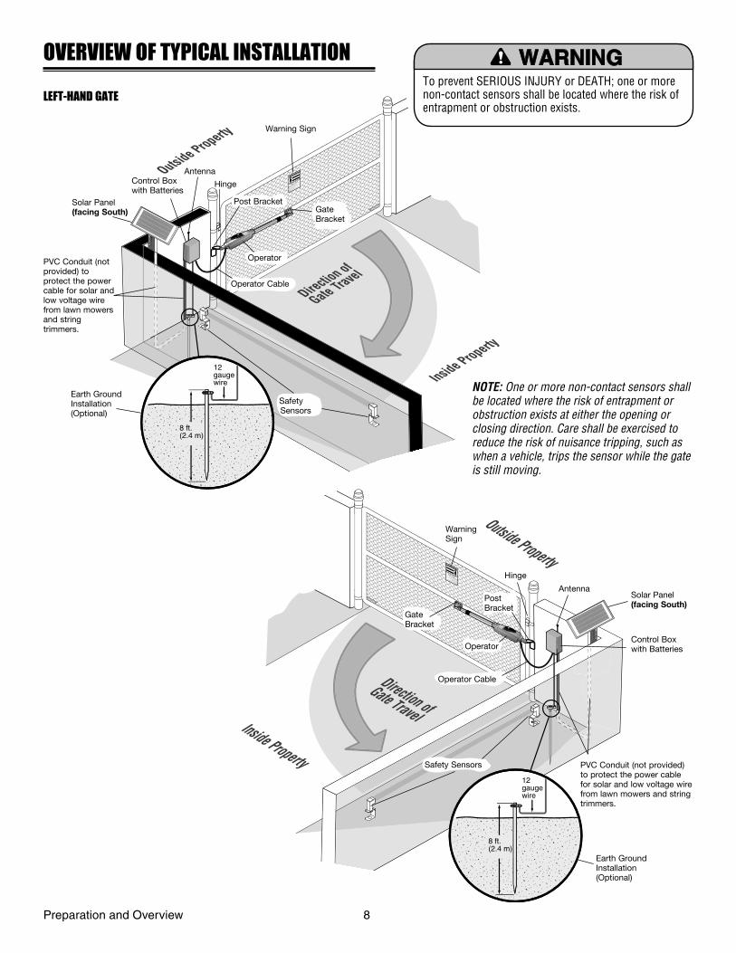
To prevent SERIOUS INJURY or DEATH; one or more non-contact sensors shall be located where the risk of entrapment or obstruction exists.
OVERVIEW OF TYPICAL INSTALLATION
Outside Property
Inside Property
Direction of
Gate ravel
Moving Gate Can Cause
Injury or Death
KEEP CLEAR! Gate may move at any
time without prior warning.
Do not let children operate the gate or
play in the gate area.
This entrance is for vehicles only
Pedestrians must use separate entrance
T
12 gaugewire
8 ft.(2.4 m)
LEFT-HAND GATE
Warning Sign
Solar Panel (facing South)
Control Box with Batteries
Antenna
PVC Conduit (not provided) to protect the power cable for solar and low voltage wire from lawn mowers and string trimmers.
Hinge
Earth Ground Installation(Optional)
Safety Sensors
Operator Cable
Operator
Gate Bracket
Post Bracket
NOTE: One or more non-contact sensors shall be located where the risk of entrapment or obstruction exists at either the opening or closing direction. Care shall be exercised to reduce the risk of nuisance tripping, such as when a vehicle, trips the sensor while the gate is still moving.
WarningSign
Hinge
AntennaSolar Panel (facing South)
Control Box with Batteries
Post Bracket
Gate Bracket
Operator
Operator Cable
Safety Sensors PVC Conduit (not provided) to protect the power cable for solar and low voltage wire from lawn mowers and string trimmers.
Earth Ground Installation(Optional)
Preparation and Overview 8
Outside Property
Inside Property
Moving Gate Can Cause
Injury or Death
KEEP CLEAR! Gate may move at any
time without prior warning.
Do not let children operate the gate or
play in the gate area.
This entrance is for vehicles only
Pedestrians must use separate entrance
Direction of
Gate 1 ravel
T
Direction of
Gate 2 ravel
T
12 gaugewire
8 ft.(2.4 m)
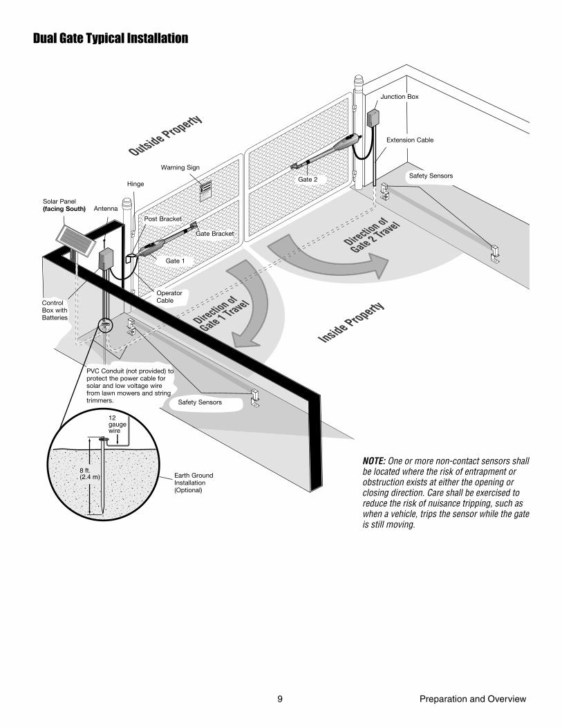
Dual Gate Typical Installation
Earth Ground Installation(Optional)
Solar Panel(facing South) Antenna
Hinge
Warning Sign
Post Bracket
Gate Bracket
Gate 1
Operator CableControl
Box with Batteries
PVC Conduit (not provided) to protect the power cable for solar and low voltage wire from lawn mowers and string trimmers. Safety Sensors
Extension Cable
Safety Sensors
Junction Box
Gate 2
9 Preparation and Overview
NOTE: One or more non-contact sensors shall be located where the risk of entrapment or obstruction exists at either the opening or closing direction. Care shall be exercised to reduce the risk of nuisance tripping, such as when a vehicle, trips the sensor while the gate is still moving.
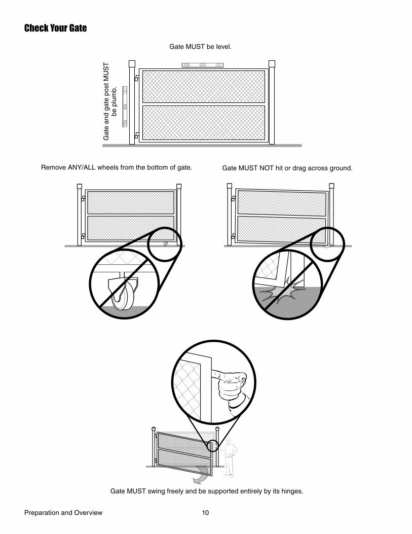
Check Your Gate
Gate MUST be level.
Gat
e an
d ga
te p
ost M
US
T
be p
lum
b.
Remove ANY/ALL wheels from the bottom of gate. Gate MUST NOT hit or drag across ground.
Gate MUST swing freely and be supported entirely by its hinges.
Preparation and Overview 10
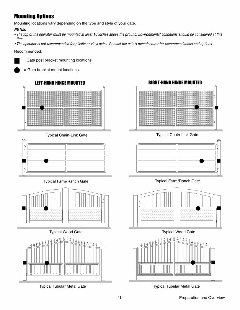
Mounting OptionsMounting locations vary depending on the type and style of your gate.
NOTES: • The top of the operator must be mounted at least 10 inches above the ground. Environmental conditions should be considered at this
time.• The operator is not recommended for plastic or vinyl gates. Contact the gate’s manufacturer for recommendations and options.
Recommended:
LEFT-HAND HINGE MOUNTED RIGHT-HAND HINGE MOUNTED
Typical Chain-Link Gate
Typical Farm/Ranch Gate
Typical Chain-Link Gate
Typical Farm/Ranch Gate
Typical Wood Gate Typical Wood Gate
Typical Tubular Metal Gate Typical Tubular Metal Gate
= Gate post bracket mounting locations
= Gate bracket mount locations
11 Preparation and Overview
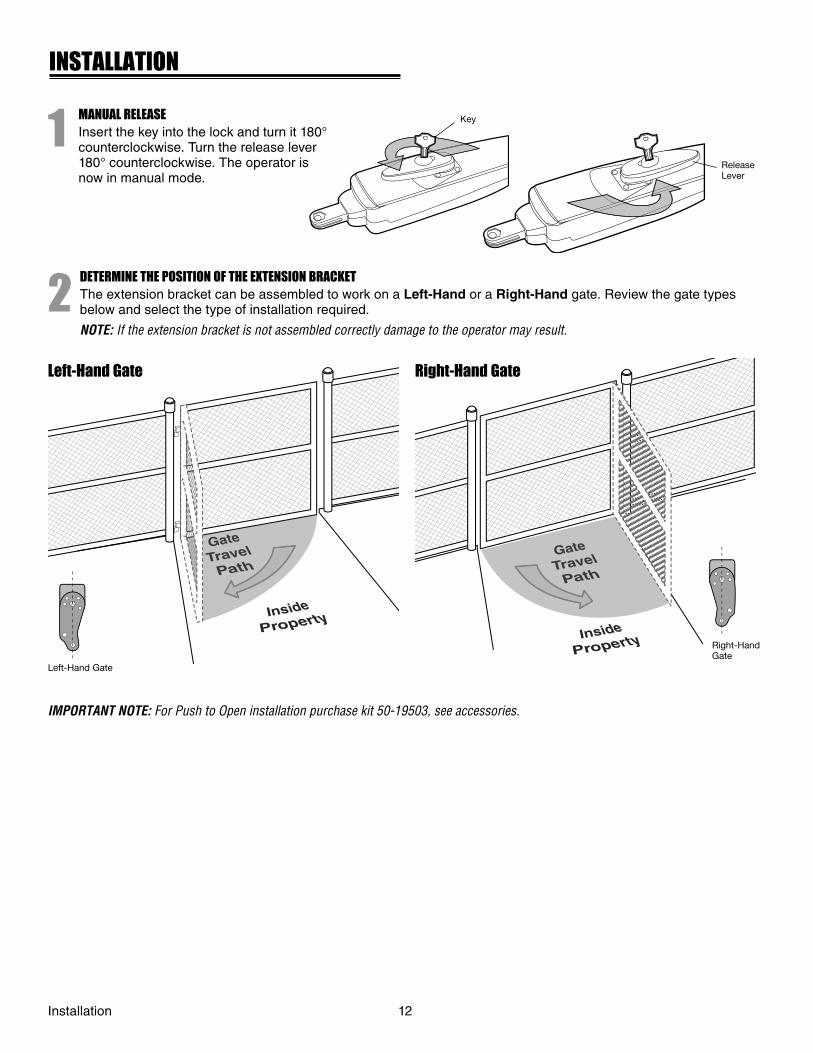
1MANUAL RELEASEInsert the key into the lock and turn it 180° counterclockwise. Turn the release lever 180° counterclockwise. The operator is now in manual mode.
2DETERMINE THE POSITION OF THE EXTENSION BRACKETThe extension bracket can be assembled to work on a Left-Hand or a Right-Hand gate. Review the gate types below and select the type of installation required.
NOTE: If the extension bracket is not assembled correctly damage to the operator may result.
Left-Hand Gate
IMPORTANT NOTE: For Push to Open installation purchase kit 50-19503, see accessories.
Right-Hand Gate
Left-Hand Gate Right-Hand Gate
Key
Release Lever
INSTALLATION
Installation 12
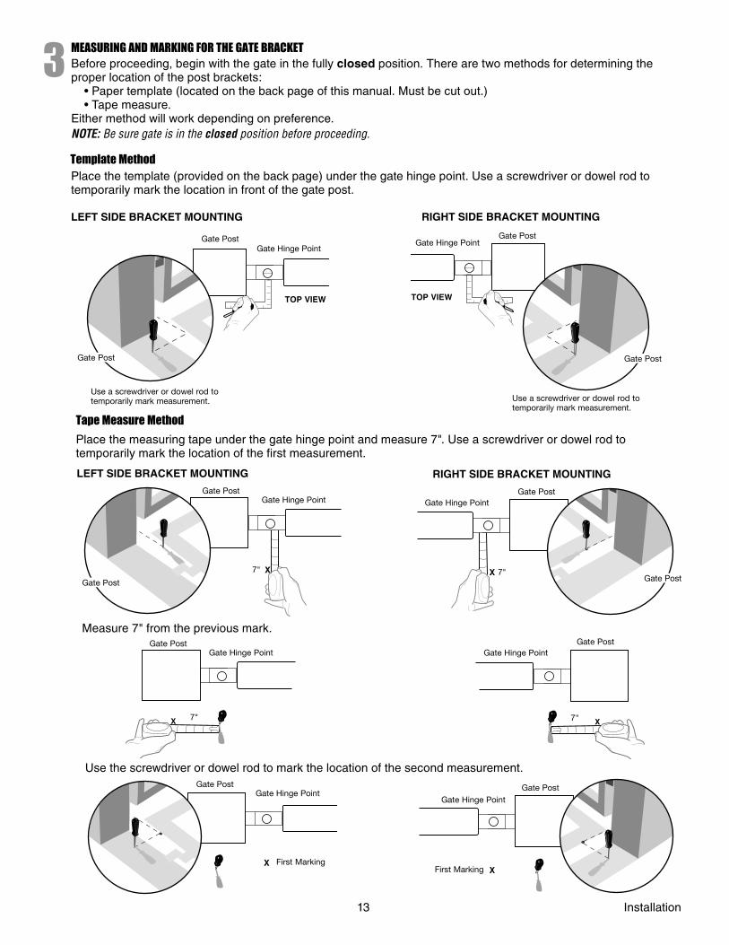
3MEASURING AND MARKING FOR THE GATE BRACKETBefore proceeding, begin with the gate in the fully closed position. There are two methods for determining the proper location of the post brackets: • Paper template (located on the back page of this manual. Must be cut out.) • Tape measure. Either method will work depending on preference. NOTE: Be sure gate is in the closed position before proceeding.
Template MethodPlace the template (provided on the back page) under the gate hinge point. Use a screwdriver or dowel rod to temporarily mark the location in front of the gate post.
LEFT SIDE BRACKET MOUNTING
Gate PostGate Hinge Point
TOP VIEW
Gate Post
Use a screwdriver or dowel rod to temporarily mark measurement.
RIGHT SIDE BRACKET MOUNTING
Gate Hinge PointGate Post
Gate Post
Use a screwdriver or dowel rod to temporarily mark measurement.
TOP VIEW
Tape Measure Method
Place the measuring tape under the gate hinge point and measure 7". Use a screwdriver or dowel rod to temporarily mark the location of the fi rst measurement.
LEFT SIDE BRACKET MOUNTING
X
Gate PostGate Hinge Point
Gate Post
7" X
Gate PostGate Hinge Point
Gate Post7"
RIGHT SIDE BRACKET MOUNTING
Measure 7" from the previous mark.
X
Gate PostGate Hinge Point
7" X
Gate PostGate Hinge Point
7"
Use the screwdriver or dowel rod to mark the location of the second measurement.
X
Gate PostGate Hinge Point
First MarkingX
Gate PostGate Hinge Point
First Marking
13 Installation
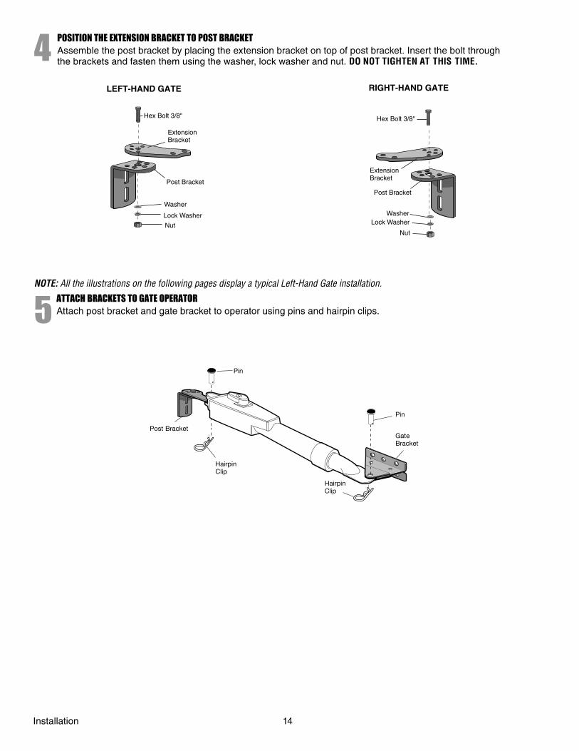
4POSITION THE EXTENSION BRACKET TO POST BRACKETAssemble the post bracket by placing the extension bracket on top of post bracket. Insert the bolt through the brackets and fasten them using the washer, lock washer and nut. DO NOT TIGHTEN AT THIS TIME.
Lock Washer
Nut
Hex Bolt 3/8"
Extension Bracket
Post Bracket
Washer
Hex Bolt 3/8"
Extension Bracket
Post Bracket
Lock Washer
Nut
Washer
LEFT-HAND GATE RIGHT-HAND GATE
NOTE: All the illustrations on the following pages display a typical Left-Hand Gate installation.
5ATTACH BRACKETS TO GATE OPERATORAttach post bracket and gate bracket to operator using pins and hairpin clips.
Pin
Pin
Gate Bracket
Hairpin Clip
Hairpin Clip
Post Bracket
Installation 14
6
7
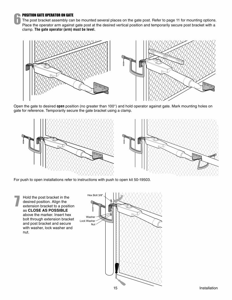
POSITION GATE OPERATOR ON GATEThe post bracket assembly can be mounted several places on the gate post. Refer to page 11 for mounting options.Place the operator arm against gate post at the desired vertical position and temporarily secure post bracket with a clamp. The gate operator (arm) must be level.
Open the gate to desired open position (no greater than 100°) and hold operator against gate. Mark mounting holes on gate for reference. Temporarily secure the gate bracket using a clamp.
For push to open installations refer to instructions with push to open kit 50-19503.
Hold the post bracket in the desired position. Align the extension bracket to a position as CLOSE AS POSSIBLE above the marker. Insert hex bolt through extension bracket and post bracket and secure with washer, lock washer and nut.
Hex Bolt 3/8"
Lock WasherNut
Washer
15 Installation
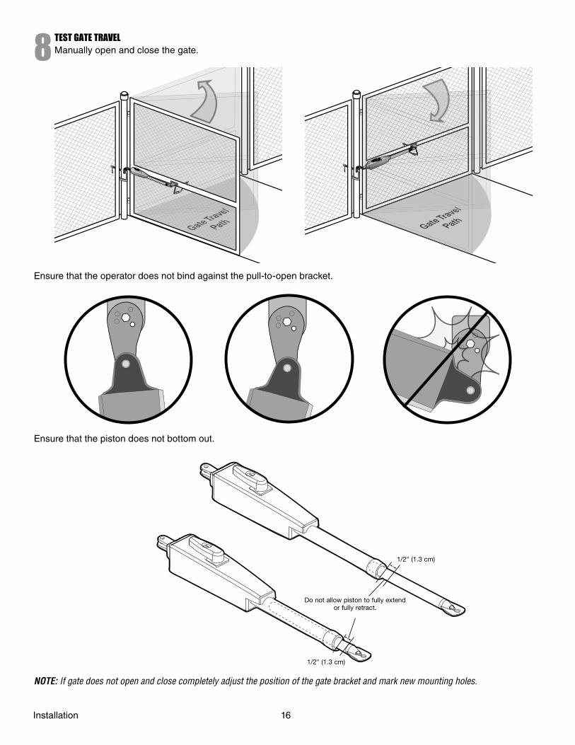
8TEST GATE TRAVELManually open and close the gate.
Ensure that the operator does not bind against the pull-to-open bracket.
Ensure that the piston does not bottom out.
1/2" (1.3 cm)
Do not allow piston to fully extend or fully retract.
1/2" (1.3 cm)
NOTE: If gate does not open and close completely adjust the position of the gate bracket and mark new mounting holes.
Installation 16
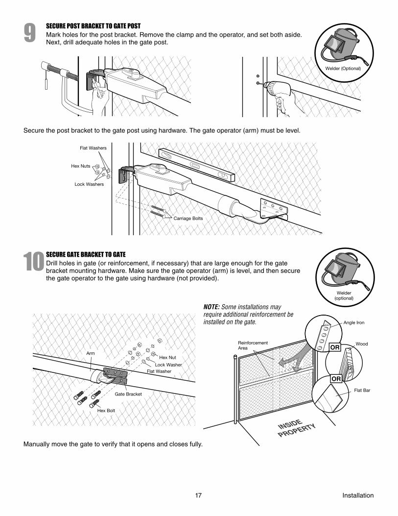
9SECURE POST BRACKET TO GATE POSTMark holes for the post bracket. Remove the clamp and the operator, and set both aside. Next, drill adequate holes in the gate post.
Welder (Optional)
Secure the post bracket to the gate post using hardware. The gate operator (arm) must be level.
Flat Washers
Hex Nuts
Lock Washers
Carriage Bolts
10SECURE GATE BRACKET TO GATEDrill holes in gate (or reinforcement, if necessary) that are large enough for the gate bracket mounting hardware. Make sure the gate operator (arm) is level, and then secure the gate operator to the gate using hardware (not provided).
Welder (optional)
ArmHex Nut
Lock WasherFlat Washer
Gate Bracket
Hex Bolt
OR
OR
NOTE: Some installations may require additional reinforcement be installed on the gate.
Reinforcement Area
Angle Iron
Wood
Flat Bar
Manually move the gate to verify that it opens and closes fully.
17 Installation
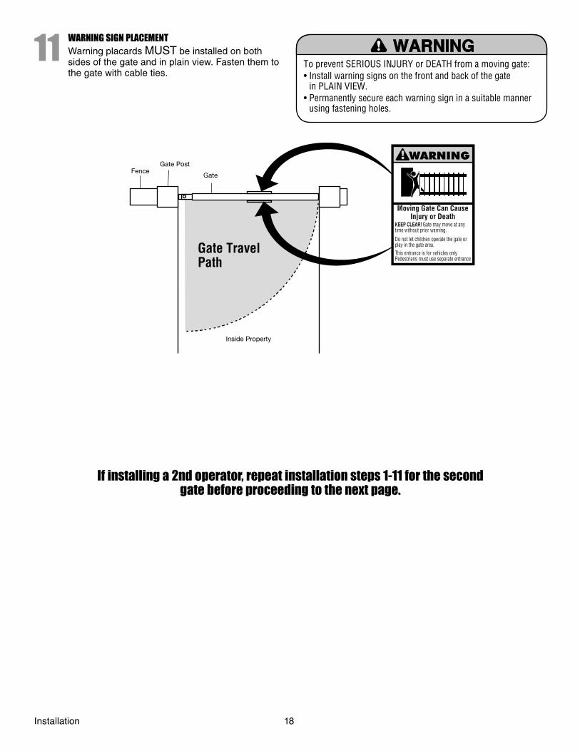
To prevent SERIOUS INJURY or DEATH from a moving gate:• Install warning signs on the front and back of the gate
in PLAIN VIEW.• Permanently secure each warning sign in a suitable manner
using fastening holes.
11WARNING SIGN PLACEMENTWarning placards MUST be installed on both sides of the gate and in plain view. Fasten them to the gate with cable ties.
Gate Travel Path
Moving Gate Can CauseInjury or Death
KEEP CLEAR! Gate may move at anytime without prior warning.
Do not let children operate the gate orplay in the gate area.This entrance is for vehicles onlyPedestrians must use separate entrance
FenceGate Post
Gate
Inside Property
If installing a 2nd operator, repeat installation steps 1-11 for the second gate before proceeding to the next page.
Installation 18
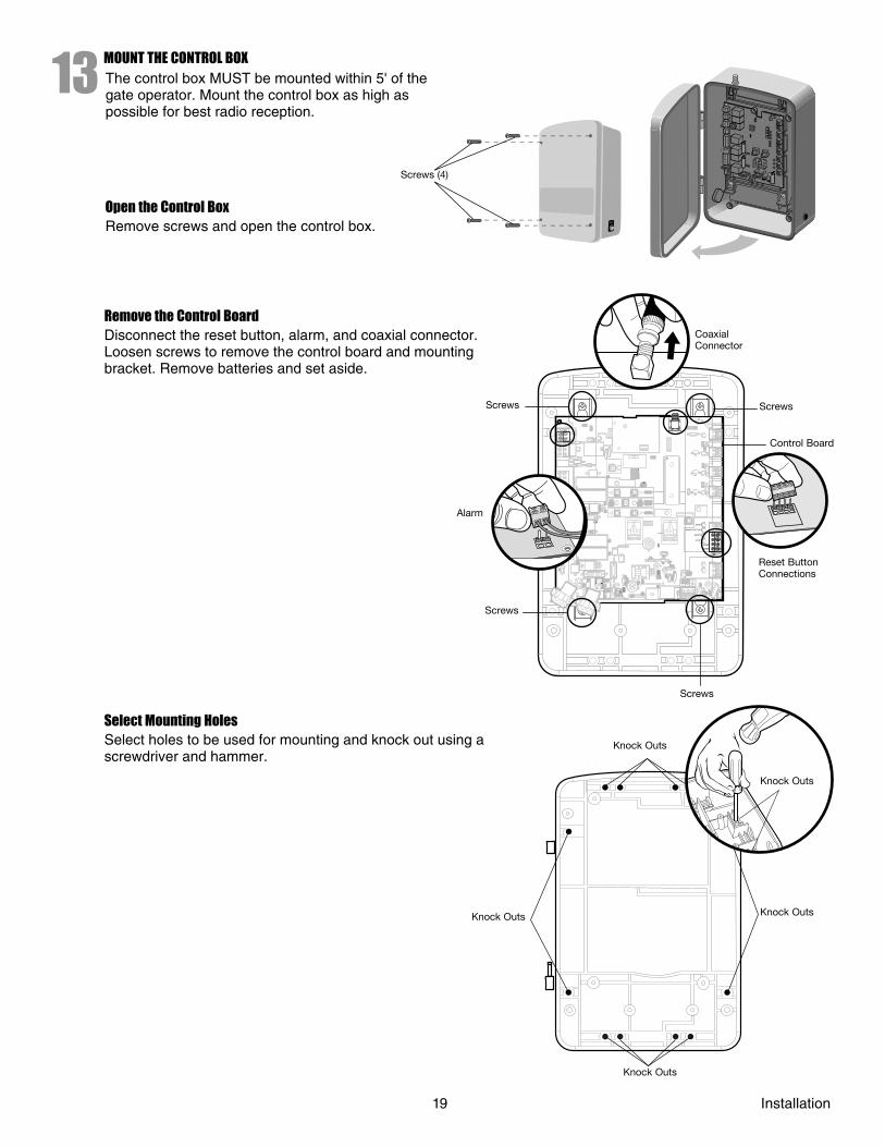
13MOUNT THE CONTROL BOXThe control box MUST be mounted within 5' of the gate operator. Mount the control box as high as possible for best radio reception.
RESET
Screws (4)
Open the Control BoxRemove screws and open the control box.
Remove the Control BoardDisconnect the reset button, alarm, and coaxial connector. Loosen screws to remove the control board and mounting bracket. Remove batteries and set aside.
1818
L1L1
K2
K2
Z22
Z22
F2
F2
MO
V1
MO
V1
D1
D1
OPEN
SINGLE BUTTON
RESET
STOP
CHGRCHGROVLDOVLD
COM
COM
D129D129
Z4Z4
D2D2
C11
C11
C13C13
D16
D16
F9
F9
K1
K1
F3F3
K3
K3
K4
K4
F1F1
Z12Z12
GATE 2GATE 2
GATE 1
GRGR
WHWH
YLYL
BLBL
RDRD
BRBR
GRGR
WHWH
YLYL
BLBL
RDRD
BRBR
F7F7
24V24V
CTRLCTRLOVLDOVLD
TIMERTIMERRUNNINGRUNNING
GATE 2GATE 2
SETSETOPENOPENLIMITLIMIT
SETSETCLOSECLOSELIMITLIMIT
LEARNLEARNLIMITSLIMITS
GATE 1GATE 1
LEARNLEARNXMITTERXMITTER
LOCK /LOCK /
ONON OFFOFF
C69
C69
PWRPWR
AC PWRAC PWR/SOLAR/SOLAR
R329
R329R
27R
27
MO
V2
MO
V2
R4
R4
C2
C2
BIPART DELAYBIPART DELAY
LOCK
Q9
Q9
R9R9Ø
F8F8
C73C73
C72C72
C71C71
C7C7Ø
R42R42ØR423R423
J24 J23 3J24 J23 3Ø
A 32V
A 32V
3 3ØA
32VA
32V
J21J21
3030
3030 C64
C64
R22R22U2U2
K6K6
JU1
JU1
JU1
JU1
JU2JU2DB1DB1
R184R184
ALARM
1818
K2
K2
Z22
Z22
F2
F2
MO
V1
MO
V1
D1
D1
D129D129
Z4Z4
D2D2
C11
C11
C13C13
D16
D16
F9
F9
K1
K1
F3F3
K3
K3
K4
K4
F1F1
Z12Z12
GATE 2GATE 2
GRGR
WHWH
YLYL
BLBL
RDRD
BRBR
F7F7
24V24V
GATE 2GATE 2
SETSETOPENOPENLIMITLIMIT
SETSETCLOSECLOSELIMITLIMIT
LEARNLEARNLIMITSLIMITS
GATE 1GATE 1
C69
C69
R329
R329R
27R
27
MO
V2
MO
V2
R4
R4
C2
C2
Q9
Q9
R9R9Ø
F8F8
C73C73
C72C72
C71C71
C7C7Ø
R42R42ØR423R423
J24 J23 3J24 J23 3Ø
A 32V
A 32V
3 3ØA
32VA
32V
J21J21
3030
3030 C64
C64
R22R22U2U2
K6K6
JU1
JU1
JU2JU2DB1DB1
18
L1
K2
Z22
F2
MO
V1
D1
CHGROVLD
D129
Z4
D2
C11
C13
D16
F9
K1
F3
K3
K4
F1
Z12
GATE 2
GR
WH
YL
BL
RD
BR
GR
WH
YL
BL
RD
BR
F7
24V
CTRLOVLD
TIMERRUNNING
GATE 2
SETOPENLIMIT
SETCLOSELIMIT
LEARNLIMITS
GATE 1
LEARNXMITTER
LOCK /
ON OFF
C69
PWR
AC PWR/SOLAR
R329R
27
MO
V2
R4
C2
BIPART DELAY
Q9
R9Ø
F8
C73
C72
C71
C7Ø
R42ØR423
J24 J23 3ØA
32V
3ØA
32V
J21
30
30 C64
R22U2
K6
JU1
JU1
JU2DB1
R184
18
K2
Z22
F2
MO
V1
D1
D129
Z4
D2
C11
C13
D16
F9
K1
F3
K3
K4
F1
Z12
GATE 2
GR
WH
YL
BL
RD
BR
F7
24V
GATE 2
SETOPENLIMIT
SETCLOSELIMIT
LEARNLIMITS
GATE 1
C69
R329R
27
MO
V2
R4
C2
Q9
R9Ø
F8
C73
C72
C71
C7Ø
R42ØR423
J24 J23 3ØA
32V
3 ØA
32V
J21
30
30 C64
R22U2
K6
JU1
JU2DB1
18
L1
K2
Z22
F2
MO
V1
D1
CHGROVLD
D129
Z4
D2
C11
C13
D16
F9
K1
F3
K3
K4
F1
Z12
GATE 2
GR
WH
YL
BL
RD
BR
GR
WH
YL
BL
RD
BR
F7
24V
CTRLOVLD
TIMERRUNNING
GATE 2
SETOPENLIMIT
SETCLOSELIMIT
LEARNLIMITS
GATE 1
LEARNXMITTER
LOCK /
ON OFF
C69
PWR
AC PWR/SOLAR
R329R
27
MO
V2
R4
C2
BIPART DELAY
Q9
R9Ø
F8
C73
C72
C71
C7Ø
R42ØR423
J24 J23 3ØA
32V
3ØA
32V
J21
30
30 C64
R22U2
K6
JU1
JU1
JU2DB1
R184
18
K2
Z22
F2
MO
V1
D1
D129
Z4
D2
C11
C13
D16
F9
K1
F3
K3
K4
F1
Z12
GATE 2
GR
WH
YL
BL
RD
BR
F7
24V
GATE 2
SETOPENLIMIT
SETCLOSELIMIT
LEARNLIMITS
GATE 1
C69
R329R
27
MO
V2
R4
C2
Q9
R9Ø
F8
C73
C72
C71
C7Ø
R42ØR423
J24 J23 3ØA
32V
3 ØA
32V
J21
30
30 C64
R22U2
K6
JU1
JU2DB1
Coaxial Connector
Screws
Control Board
Reset Button Connections
Screws
Screws
Screws
Alarm
Select Mounting HolesSelect holes to be used for mounting and knock out using a screwdriver and hammer.
Knock Outs
Knock Outs
Knock Outs
Knock Outs
Knock Outs
19 Installation
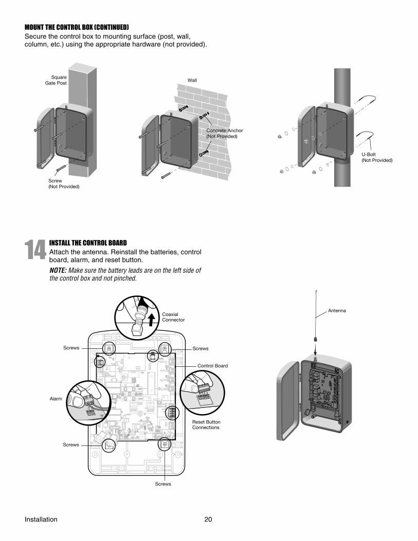
MOUNT THE CONTROL BOX (CONTINUED)Secure the control box to mounting surface (post, wall, column, etc.) using the appropriate hardware (not provided).
14 INSTALL THE CONTROL BOARDAttach the antenna. Reinstall the batteries, control board, alarm, and reset button.
NOTE: Make sure the battery leads are on the left side of the control box and not pinched.
Square Gate Post
Screw(Not Provided)
Concrete Anchor(Not Provided)
Wall
U-Bolt (Not Provided)
Antenna
1818
L1L1
K2
K2
Z22
Z22
F2
F2
MO
V1
MO
V1
D1
D1
OPEN
SINGLE BUTTON
RESET
STOP
CHGRCHGROVLDOVLD
COM
COM
D129D129
Z4Z4
D2D2
C11
C11
C13C13
D16
D16
F9
F9
K1
K1
F3F3
K3
K3
K4
K4
F1F1
Z12Z12
GATE 2GATE 2
GATE 1
GRGR
WHWH
YLYL
BLBL
RDRD
BRBR
GRGR
WHWH
YLYL
BLBL
RDRD
BRBR
F7F7
24V24V
CTRLCTRLOVLDOVLD
TIMERTIMERRUNNINGRUNNING
GATE 2GATE 2
SETSETOPENOPENLIMITLIMIT
SETSETCLOSECLOSELIMITLIMIT
LEARNLEARNLIMITSLIMITS
GATE 1GATE 1
LEARNLEARNXMITTERXMITTER
LOCK /LOCK /
ONON OFFOFF
C69
C69
PWRPWR
AC PWRAC PWR/SOLAR/SOLAR
R329
R329R
27R
27
MO
V2
MO
V2
R4
R4
C2
C2
BIPART DELAYBIPART DELAY
LOCK
Q9
Q9
R9R9Ø
F8F8
C73C73
C72C72
C71C71
C7C7Ø
R42R42ØR423R423
J24 J23 3J24 J23 3Ø
A 32V
A 32V
3 3ØA
32VA
32V
J21J21
3030
3030 C64
C64
R22R22U2U2
K6K6
JU1
JU1
JU1
JU1
JU2JU2DB1DB1
R184R184
ALARM
1818
K2
K2
Z22
Z22
F2
F2
MO
V1
MO
V1
D1
D1
D129D129
Z4Z4
D2D2
C11
C11
C13C13
D16
D16
F9
F9
K1
K1
F3F3
K3
K3
K4
K4
F1F1
Z12Z12
GATE 2GATE 2
GRGR
WHWH
YLYL
BLBL
RDRD
BRBR
F7F7
24V24V
GATE 2GATE 2
SETSETOPENOPENLIMITLIMIT
SETSETCLOSECLOSELIMITLIMIT
LEARNLEARNLIMITSLIMITS
GATE 1GATE 1
C69
C69
R329
R329R
27R
27
MO
V2
MO
V2
R4
R4
C2
C2
Q9
Q9
R9R9Ø
F8F8
C73C73
C72C72
C71C71
C7C7Ø
R42R42ØR423R423
J24 J23 3J24 J23 3Ø
A 32V
A 32V
3 3ØA
32VA
32V
J21J21
3030
3030 C64
C64
R22R22U2U2
K6K6
JU1
JU1
JU2JU2DB1DB1
18
L1
K2
Z22
F2
MO
V1
D1
CHGROVLD
D129
Z4
D2
C11
C13
D16
F9
K1
F3
K3
K4
F1
Z12
GATE 2
GR
WH
YL
BL
RD
BR
GR
WH
YL
BL
RD
BR
F7
24V
CTRLOVLD
TIMERRUNNING
GATE 2
SETOPENLIMIT
SETCLOSELIMIT
LEARNLIMITS
GATE 1
LEARNXMITTER
LOCK /
ON OFF
C69
PWR
AC PWR/SOLAR
R329R
27
MO
V2
R4
C2
BIPART DELAY
Q9
R9Ø
F8
C73
C72
C71
C7Ø
R42ØR423
J24 J23 3ØA
32V
3ØA
32V
J21
30
30 C64
R22U2
K6
JU1
JU1
JU2DB1
R184
18
K2
Z22
F2
MO
V1
D1
D129
Z4
D2
C11
C13
D16
F9
K1
F3
K3
K4
F1
Z12
GATE 2
GR
WH
YL
BL
RD
BR
F7
24V
GATE 2
SETOPENLIMIT
SETCLOSELIMIT
LEARNLIMITS
GATE 1
C69
R329R
27
MO
V2
R4
C2
Q9
R9Ø
F8
C73
C72
C71
C7Ø
R42ØR423
J24 J23 3ØA
32V
3 ØA
32V
J21
30
30 C64
R22U2
K6
JU1
JU2DB1
18
L1
K2
Z22
F2
MO
V1
D1
CHGROVLD
D129
Z4
D2
C11
C13
D16
F9
K1
F3
K3
K4
F1
Z12
GATE 2
GR
WH
YL
BL
RD
BR
GR
WH
YL
BL
RD
BR
F7
24V
CTRLOVLD
TIMERRUNNING
GATE 2
SETOPENLIMIT
SETCLOSELIMIT
LEARNLIMITS
GATE 1
LEARNXMITTER
LOCK /
ON OFF
C69
PWR
AC PWR/SOLAR
R329R
27
MO
V2
R4
C2
BIPART DELAY
Q9
R9Ø
F8
C73
C72
C71
C7Ø
R42ØR423
J24 J23 3ØA
32V
3ØA
32V
J21
30
30 C64
R22U2
K6
JU1
JU1
JU2DB1
R184
18
K2
Z22
F2
MO
V1
D1
D129
Z4
D2
C11
C13
D16
F9
K1
F3
K3
K4
F1
Z12
GATE 2
GR
WH
YL
BL
RD
BR
F7
24V
GATE 2
SETOPENLIMIT
SETCLOSELIMIT
LEARNLIMITS
GATE 1
C69
R329R
27
MO
V2
R4
C2
Q9
R9Ø
F8
C73
C72
C71
C7Ø
R42ØR423
J24 J23 3ØA
32V
3 ØA
32V
J21
30
30 C64
R22U2
K6
JU1
JU2DB1
18
L1
K2
Z22
F2
MO
V1
D1
CHGROVLD
D129
Z4
D2
C11
C13
D16
F9
K1
F3
K3
K4
F1
Z12
GATE 2
GR
WH
YL
BL
RD
BR
GR
WH
YL
BL
RD
BR
F7
24V
CTRLOVLD
TIMERRUNNING
GATE 2
SETOPENLIMIT
SETCLOSELIMIT
LEARNLIMITS
GATE 1
LEARNXMITTER
LOCK /
ON OFF
C69
PWR
AC PWR/SOLAR
R329R
27
MO
V2
R4
C2
BIPART DELAY
Q9
R9Ø
F8
C73
C72
C71
C7Ø
R42ØR423
J24 J23 3ØA
32V
3ØA
32V
J21
30
30 C64
R22U2
K6
JU1
JU1
JU2DB1
R184
18
K2
Z22
F2
MO
V1
D1
D129
Z4
D2
C11
C13
D16
F9
K1
F3
K3
K4
F1
Z12
GATE 2
GR
WH
YL
BL
RD
BR
F7
24V
GATE 2
SETOPENLIMIT
SETCLOSELIMIT
LEARNLIMITS
GATE 1
C69
R329R
27
MO
V2
R4
C2
Q9
R9Ø
F8
C73
C72
C71
C7Ø
R42ØR423
J24 J23 3ØA
32V
3 ØA
32V
J21
30
30 C64
R22U2
K6
JU1
JU2DB1
Coaxial Connector
Screws
Control Board
Reset Button Connections
Screws
Screws
Screws
Alarm
Installation 20
FUSEOPEN
Moving Gate Can Cause
Injury or Death
KEEP CLEAR! Gate may move at any
time without prior warning.
Do not let children operate the gate or
play in the gate area.
This entrance is for vehicles only
Pedestrians must use separate entrance
FUSE OPEN
C4 Control Box
1818R93R93
D42
K2
K2
Z22
Z22
P1
P1
F2
F2
MO
V1
D1
D1
Q12
D129
Z4
U3
U3 D2D2
D44
C11
C11
C13
D16
D16
F9
F9
K1
K1
Q22
F3F3
K3
K4
R196
F1F1
Z12Z12
GATE 2GATE 2
GRGR
WHWH
YLYL
BLBL
RDRD
BRBR
F7
24V24V
GATE 2
SETSETOPENOPENLIMITLIMIT
SETSETCLOSECLOSELIMITLIMIT
LEARNLIMITS
GATE 1
C69
C69
J2Ø
D8
D4
R9
R9
R329
R329R
27R
27
MO
V2
MO
V2
R4
R4
C2
C2
Z1
K5
K5 F12 F12
Q9
Q9
R9Ø
F8F8
Q6
Q1
C75C75
C66C66 C65C65
C68
C68
C33
C33
F11
R42R42ØR423R423
J24 J23 3ØA
32V
3 3ØA
32VA
32V
J21J21
3030
3030 C64
C64
R22R22U2U2
K6K6
JU1
JU1
JU2DB1
D36D36
To reduce the risk of SEVERE INJURY or DEATH:• BEFORE installing power wiring or control stations be sure to
follow ALL specifi cations and warnings described below.• ANY maintenance to the operator or in the area near the
operator MUST not be performed until the batteries are disconnected. Upon completion of maintenance the area MUST be cleared and secured, at that time the unit may be returned to service.
• ALL electrical connections MUST be made by a qualifi ed individual.
• DO NOT install ANY wiring or attempt to run the operator without consulting the wiring diagram. We recommend that you install an optional reversing edge BEFORE proceeding with the control station installation.
ATTENTION
AVERTISSEMENT AVERTISSEMENT
AVERTISSEMENT
WARNING
CAUTION
WARNING
WARNINGWARNING
PRECAUCIÓN ADVERTENCIA
ADVERTENCIAADVERTENCIA
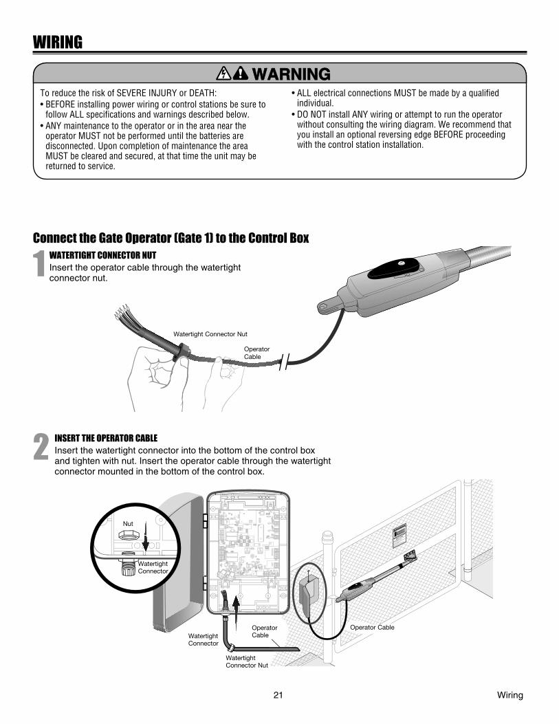
Connect the Gate Operator (Gate 1) to the Control Box
1 WATERTIGHT CONNECTOR NUTInsert the operator cable through the watertight connector nut.
Watertight Connector Nut
Operator Cable
2 INSERT THE OPERATOR CABLEInsert the watertight connector into the bottom of the control box and tighten with nut. Insert the operator cable through the watertight connector mounted in the bottom of the control box.
Nut
Watertight Connector
Operator CableWatertight
Connector
Watertight Connector Nut
Operator Cable
21 Wiring
WIRING
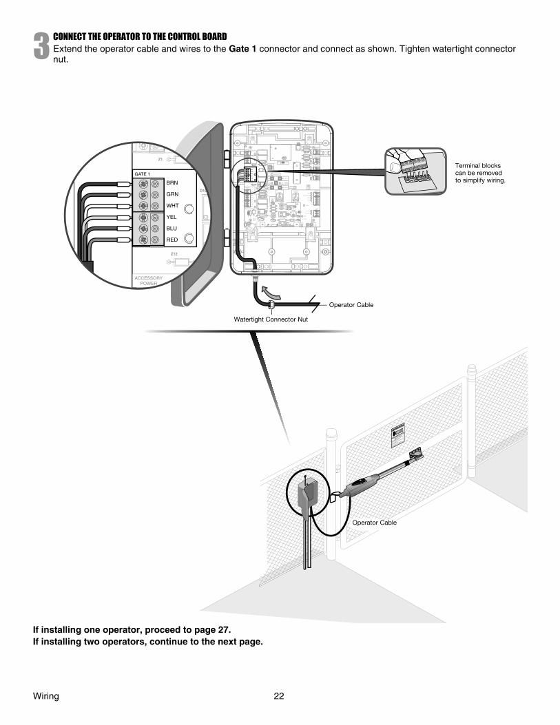
3CONNECT THE OPERATOR TO THE CONTROL BOARDExtend the operator cable and wires to the Gate 1 connector and connect as shown. Tighten watertight connector nut.
Moving Gate Can Cause
Injury or Death
KEEP CLEAR! Gate may move at any
time without prior warning.
Do not let children operate the gate or
play in the gate area.
This entrance is for vehicles only
Pedestrians must use separate entrance
Z22
R91
CLOSE EDGE
R94
R92
R93
L1
R1
R2
Z1
K5
K6
K2
F3
10A 32V
D1Ø
OPEN EDGE/ PHO T O
OPEN PHO T O
CLOSE PHO T O
R227
R2Ø7
Z2 Ø
R223
P1
Z9
Z8
F2
F6
D4
D2
R9
C64 JMPR1
R224
U4
CONTROL INPUTS
FORCE TIMER TO
CLOSE
OFF MAX
OPEN
SINGLE BUTTON
RESET
STOP
SHADOW
INTERRUPT
CHGR OVLD
COM
COM
COM
FUSE OPEN
LOOP INPUTS
POWER
BATT 1 BATT 2
F1 20A 32V
R35
D9
Z3
Z4
U3
D1
D27
F5
C11
C13
C12
D15 C2 R4
R1Ø1
R1ØØ
R9Ø
Q9 K1
R196
Q22
D8 K3
K4
D21
D22 C4
ACCESSORY OVLD
D6
JMPR2
MOV1 MOV2
DB1 U2
Z12
24 VAC/ SOLAR INPUT
GATE 2
ACCESSORY POWER
MAGLOCK
ALARM
GATE 1
C
C
NC
NO
NO
GRN
WHT
YEL
BLU
RED
BRN
GRN
WHT
YEL
BLU
RED
BRN F4
10A 32V
F7
24V
COM OVLD
TIMER RUNNING
GATE 2
SET OPEN LIMIT
SET CLOSE LIMIT
LEARN LIMITS
DIAGNOSTIC
GATE 1
J4
LEARN XMITTER
MAGLOCK ON OFF
F2
F6
U4
MAX
FUSE OPEN
C13 C4
Z1
10A 32V
D1Ø
R9Ø
Z12
ACCESSORY POWER
GATE 1
NC
GRN
WHT
YEL
BLU
RED
BRN
If installing one operator, proceed to page 27.If installing two operators, continue to the next page.
Operator Cable
Watertight Connector Nut
Operator Cable
Terminal blocks can be removed to simplify wiring.
Wiring 22
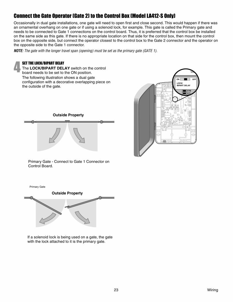
Connect the Gate Operator (Gate 2) to the Control Box (Model LA412-S Only)Occasionally in dual gate installations, one gate will need to open fi rst and close second. This would happen if there was an ornamental overhang on one gate or if using a solenoid lock, for example. This gate is called the Primary gate and needs to be connected to Gate 1 connections on the control board. Thus, it is preferred that the control box be installed on the same side as this gate. If there is no appropriate location on that side for the control box, then mount the control box on the opposite side, but connect the operator closest to the control box to the Gate 2 connector and the operator on the opposite side to the Gate 1 connector.
NOTE: The gate with the longer travel span (opening) must be set as the primary gate (GATE 1).
4 SET THE LOCK/BIPART DELAYThe LOCK/BIPART DELAY switch on the control board needs to be set to the ON position.The following illustration shows a dual gate confi guration with a decorative overlapping piece on the outside of the gate.
Control Box
1818R93R93
D42D42
K2
K2
D1D1Ø
Z22
Z22
P1
P1
F2
F2
MO
V1
MO
V1
D1
D1
Q12
Q12
U4U4
D129D129
Z4Z4
U3
U3 D2D2
D44D44
C11
C11
C13C13
D16
D16
F9
F9
R1R1Ø1R1R1ØØØØ
K1
K1
Q22Q22
F3F3
K3
K3
K4
K4
R196R196
F1F1
Z12Z12
GATE 2GATE 2
GRGR
WHWH
YLYL
BLBL
RDRD
BRBR
F7F7
24V24V
GATE 2GATE 2
SETSETOPENOPENLIMITLIMIT
SETSETCLOSECLOSELIMITLIMIT
LEARNLEARNLIMITSLIMITS
GATE 1GATE 1
C69
C69
J2J2Ø
D8
D8
D4
D4
R9
R9
R329
R329R
27R
27
MO
V2
MO
V2
R4
R4
C2
C2
Z1Z1R2R2
K5
K5 F12 F12
Q9
Q9
R9R9Ø
F8F8
Q6
Q6
Q1
Q1
C75C75
C73C73
C72C72
C71C71
C7C7Ø
C66C66 C65C65
C68
C68
C33
C33
F11
F11
R42R42ØR423R423
J24 J23 3J24 J23 3Ø
A 32V
A 32V
3 3ØA
32VA
32V
J21J21
3030
3030 C64
C64
R22R22U2U2
J18J18
K6K6
JU1
JU1
JU2JU2DB1DB1
D36D36
C71C7Ø
ON OFF
LOCK/BIPART DELAY
18R93
D42
K2
D1Ø
Z22
P1
F2
MO
V1
D1
Q12
U4
D129
Z4
U3 D2
D44
C11
C13
D16
F9
R1Ø1R1ØØ
K1
Q22
F3
K3
K4
R196
F1
Z12
GATE 2
GR
WH
YL
BL
RD
BR
F7
24V
GATE 2
SETOPENLIMIT
SETCLOSELIMIT
LEARNLIMITS
GATE 1
C69
J2 Ø
D8
D4
R9
R329R
27
MO
V2
R4
C2
Z1R2
K5 F12
Q9
R9Ø
F8
Q6
Q1
C75
C73
C72
C71
C7Ø
C66 C65
C68
C33
F11
R42ØR423
J24 J23 3ØA
32V
3 ØA
32V
J21
30
30 C64
R22U2
J18
K6
JU1
JU2DB1
D36
Outside Property
Primary Gate - Connect to Gate 1 Connector on Control Board.
Primary Gate
Outside Property
If a solenoid lock is being used on a gate, the gate with the lock attached to it is the primary gate.
23 Wiring
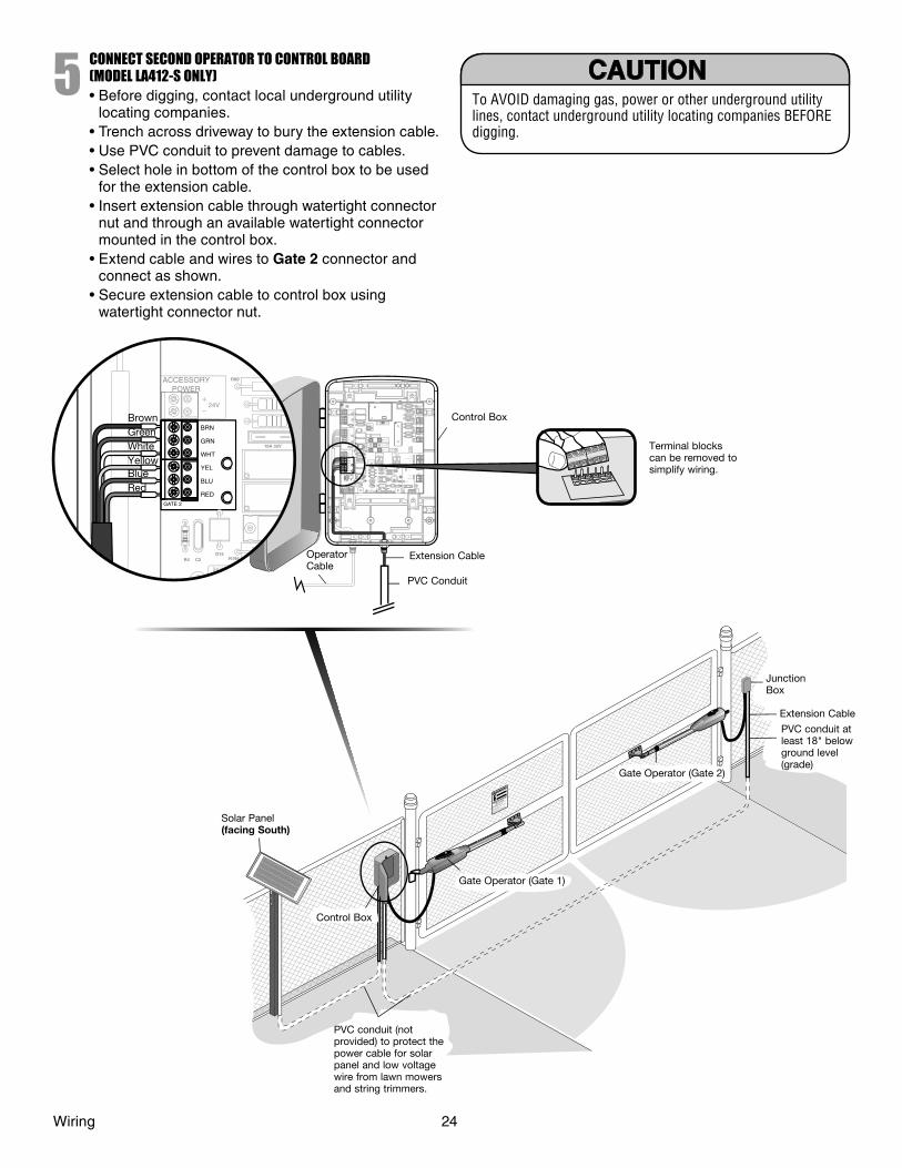
5CONNECT SECOND OPERATOR TO CONTROL BOARD(MODEL LA412-S ONLY)• Before digging, contact local underground utility
locating companies.• Trench across driveway to bury the extension cable.• Use PVC conduit to prevent damage to cables. • Select hole in bottom of the control box to be used
for the extension cable. • Insert extension cable through watertight connector
nut and through an available watertight connector mounted in the control box.
• Extend cable and wires to Gate 2 connector and connect as shown.
• Secure extension cable to control box using watertight connector nut.
To AVOID damaging gas, power or other underground utility lines, contact underground utility locating companies BEFORE digging.
P1
F2
F6
U4
MAX
C13 C4
Z22
R91
CLOSE EDGE
R94
R92
R93
L1
R1
R2
Z1
K5
K6
K2
F3
10A 32V
D1Ø
OPEN EDGE/ PHO T O
OPEN PHO T O
CLOSE PHO T O
R227
R2Ø7
Z2 Ø
R223
P1
Z9
Z8
F2
F6
D4
D2
R9
C64 JMPR1
R224
U4
CONTROL INPUTS
FORCE TIMER TO
CLOSE
OFF MAX
OPEN
SINGLE BUTTON
RESET
STOP
SHADOW
INTERRUPT
CHGR OVLD
COM
COM
COM
FUSE OPEN
LOOP INPUTS
POWER
BATT 1 BATT 2
F1 20A 32V
R35
D9
Z3
Z4
U3
D1
D27
F5
C11
C13
C12
D15 C2 R4
R1Ø1
R1ØØ
R9Ø
Q9 K1
R196
Q22
D8 K3
K4
D21
D22 C4
ACCESSORY OVLD
D6
JMPR2
MOV1 MOV2
DB1 U2
Z12
24 VAC/ SOLAR INPUT
GATE 2
ACCESSORY POWER
MAGLOCK
ALARM
GATE 1
C
C
NC
NO
NO
GRN
WHT
YEL
BLU
RED
BRN
GRN
WHT
YEL
BLU
RED
BRN F4
10A 32V
F7
24V
COM OVLD
TIMER RUNNING
GATE 2
SET OPEN LIMIT
SET CLOSE LIMIT
LEARN LIMITS
DIAGNOSTIC
GATE 1
J4
LEARN XMITTER
MAGLOCK ON OFF
D15C2R4
R9Ø
R196
24 VAC/SOLARINPUT
GATE 2
ACCESSORYPOWER
GRN
WHT
YEL
BLU
RED
BRN
10A 32V
24V
Moving Gate Can Cause
Injury or Death
KEEP CLEAR! Gate may move at any
time without prior warning.
Do not let children operate the gate or
play in the gate area.
This entrance is for vehicles only
Pedestrians must use separate entrance
Control Box
Terminal blocks can be removed to simplify wiring.
Operator Cable
Extension Cable
PVC Conduit
Solar Panel(facing South)
Control Box
Gate Operator (Gate 1)
Gate Operator (Gate 2)
Junction Box
Extension Cable
PVC conduit at least 18" below ground level (grade)
Brown
RedBlueYellowWhiteGreen
Wiring 24
PVC conduit (not provided) to protect the power cable for solar panel and low voltage wire from lawn mowers and string trimmers.
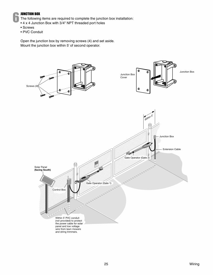
6JUNCTION BOXThe following items are required to complete the junction box installation:• 4 x 4 Junction Box with 3/4" NPT threaded port holes• Screws• PVC Conduit
Open the junction box by removing screws (4) and set aside.Mount the junction box within 5' of second operator.
Junction Box Cover
Junction Box
Moving Gate Can Cause
Injury or Death
KEEP CLEAR! Gate may move at any
time without prior warning.
Do not let children operate the gate or
play in the gate area.
This entrance is for vehicles only
Pedestrians must use separate entrance
Control Box
Gate Operator (Gate 1)
Gate Operator (Gate 2)
Extension Cable
Within 5’
Within 5' PVC conduit (not provided) to protect the power cable for solar panel and low voltage wire from lawn mowers and string trimmers.
25 Wiring
Junction Box
Solar Panel (facing South)
Screws (4)
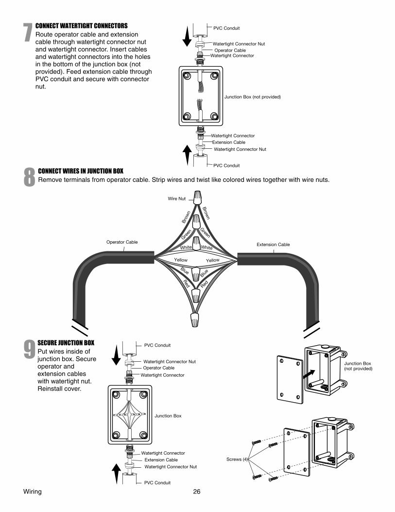
7CONNECT WATERTIGHT CONNECTORSRoute operator cable and extension cable through watertight connector nut and watertight connector. Insert cables and watertight connectors into the holes in the bottom of the junction box (not provided). Feed extension cable through PVC conduit and secure with connector nut.
Junction Box (not provided)
Watertight Connector
Watertight Connector
Extension Cable
Watertight Connector Nut
PVC Conduit
PVC Conduit
Watertight Connector NutOperator Cable
8 CONNECT WIRES IN JUNCTION BOXRemove terminals from operator cable. Strip wires and twist like colored wires together with wire nuts.
Wire Nut
Operator Cable Extension Cable
Yellow
Blue
Red
Blue
Red
White White
Brow
n
Green
Bro
wn
Green
Yellow
9 SECURE JUNCTION BOXPut wires inside of junction box. Secure operator and extension cables with watertight nut. Reinstall cover.
Wiring 26
Junction Box
Extension Cable
Watertight Connector Nut
PVC Conduit
PVC Conduit
Watertight Connector Nut
Operator CableJunction Box (not provided)
Screws (4)
Watertight Connector
Watertight Connector

SOLAR PANEL INSTALLATION
Select Site for Solar Panel(s)The solar panel(s) must be located in an open area clear of obstructions and shading for the entire day. The solar panel(s) comes with a 10' cable. If a location near the control box cannot be found, an additional cable will be required. The LA412 Solar Gate Operator is not supported in northern climates where temperatures reach below -4F. This is due to cold weather and a reduced number of hours of sunlight during the winter months. Cycle rate may vary from solar chart for areas that reach below 32F. Solar panels should be cleaned on a regular basis for best performance to ensure proper operation.
NUMBER OF CYCLES PER DAY
10W SOLAR Arm Only
Zone 150
Zone 240
Zone 312
1
1
1
2
3
3
Single Arm Installations
1 PANEL
AccessoriesSolenoid Lock 50 35 10Loop 50 31 10LM202 50 31 10
20W SOLAR Arm Only 50 50 282 PANEL
AccessoriesSolenoid Lock 50 50 25Loop 50 50 26LM202 50 50 26
30W SOLAR Arm Only 50 50 463 PANEL
AccessoriesSolenoid Lock 50 50 40Loop 50 50 44LM202 50 50 44
NUMBER OF CYCLES PER DAY
10W SOLAR Arms Only
Zone 150
Zone 225
Zone 38
Dual Arm Installations
1 PANEL
AccessoriesSolenoid Lock 50 23 7Loop 50 23 6LM202 50 23 6
20W SOLAR Arms Only 50 50 202 PANEL
AccessoriesSolenoid Lock 50 50 18Loop 50 50 18LM202 50 50 18
30W SOLAR Arms Only 50 50 303 PANEL
AccessoriesSolenoid Lock 50 50 27Loop 50 50 28LM202 50 50 28
4
4
4
NOT AVAILABLENOT AVAILABLE
The map (above) and cycles/day ratings are approximations and do not account for installed accessories that draw additional battery power. Ratings vary based on gate construction and installation. They are also shown for using a single 10W solar panel in conjunction with two 12 Volt 7.0 AH batteries. Ratings will improve by adding additional 10W solar panels. If required, up to three 10W panels (30W total) can be wired in parallel to increase the number of cycles per day.
NOTE: The solar panel(s) recommendation is based upon the average solar radiation and the temperature effects on batteries in the given regions. Local geography and weather conditions may require additional solar panels. Solar panels cannot be installed in areas that experience heavy fog or lake effect rain and snow.
27 Solar Panel Installation
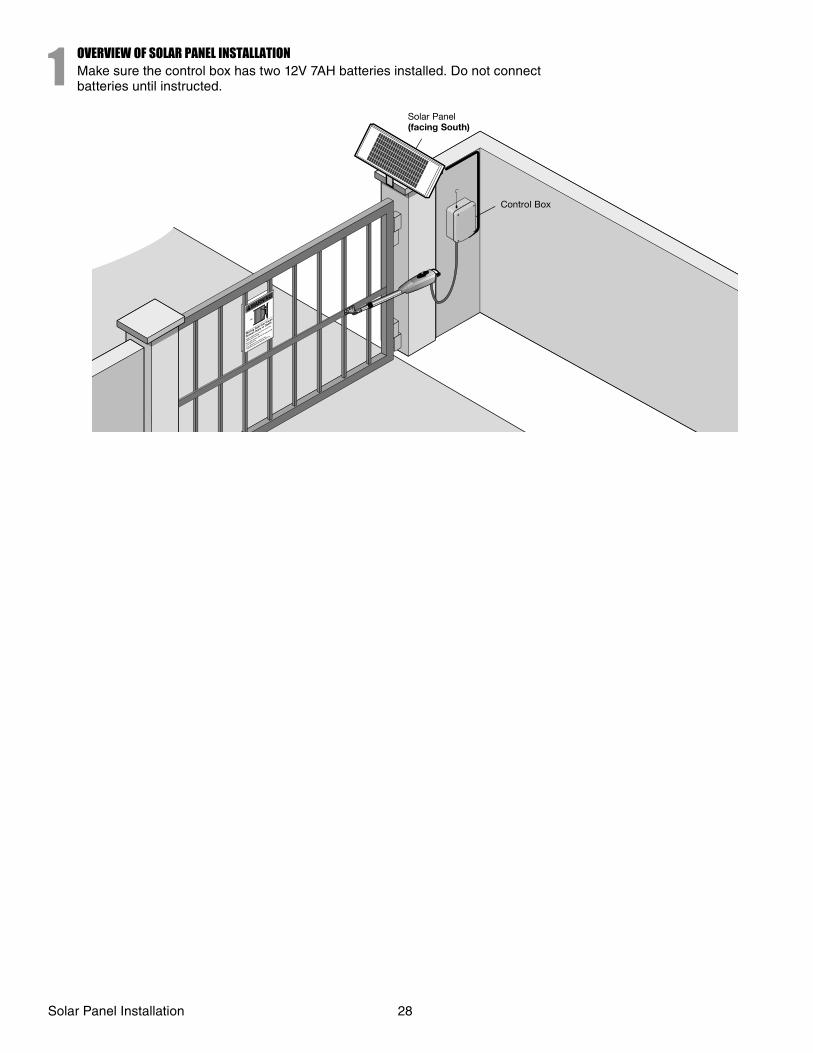
1OVERVIEW OF SOLAR PANEL INSTALLATIONMake sure the control box has two 12V 7AH batteries installed. Do not connect batteries until instructed.
Solar Panel (facing South)
Control Box
Solar Panel Installation 28
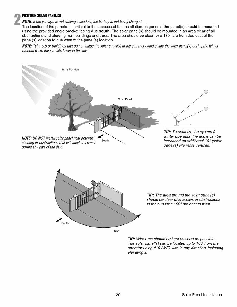
2POSITION SOLAR PANEL(S)
NOTE: If the panel(s) is not casting a shadow, the battery is not being charged.The location of the panel(s) is critical to the success of the installation. In general, the panel(s) should be mounted using the provided angle bracket facing due south. The solar panel(s) should be mounted in an area clear of all obstructions and shading from buildings and trees. The area should be clear for a 180° arc from due east of the panel(s) location to due west of the panel(s) location.
NOTE: Tall trees or buildings that do not shade the solar panel(s) in the summer could shade the solar panel(s) during the winter months when the sun sits lower in the sky.
Sun’s Position
Solar Panel
SouthNOTE: DO NOT install solar panel near potential shading or obstructions that will block the panel during any part of the day.
TIP: To optimize the system for winter operation the angle can be increased an additional 15° (solar panel(s) sits more vertical).
TIP: The area around the solar panel(s) should be clear of shadows or obstructions to the sun for a 180° arc east to west.
TIP: Wire runs should be kept as short as possible. The solar panel(s) can be located up to 100' from the operator using #16 AWG wire in any direction, including elevating it.
180°
South
29 Solar Panel Installation
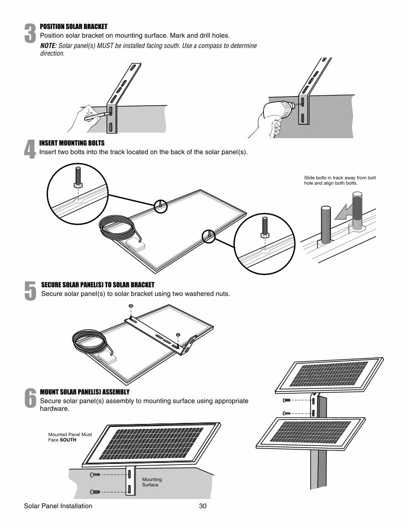
3POSITION SOLAR BRACKETPosition solar bracket on mounting surface. Mark and drill holes.
NOTE: Solar panel(s) MUST be installed facing south. Use a compass to determine direction.
4 INSERT MOUNTING BOLTSInsert two bolts into the track located on the back of the solar panel(s).
Slide bolts in track away from bolt hole and align both bolts.
5 SECURE SOLAR PANEL(S) TO SOLAR BRACKETSecure solar panel(s) to solar bracket using two washered nuts.
6 MOUNT SOLAR PANEL(S) ASSEMBLYSecure solar panel(s) assembly to mounting surface using appropriate hardware.
Mounted Panel Must Face SOUTH
Mounting Surface
Solar Panel Installation 30
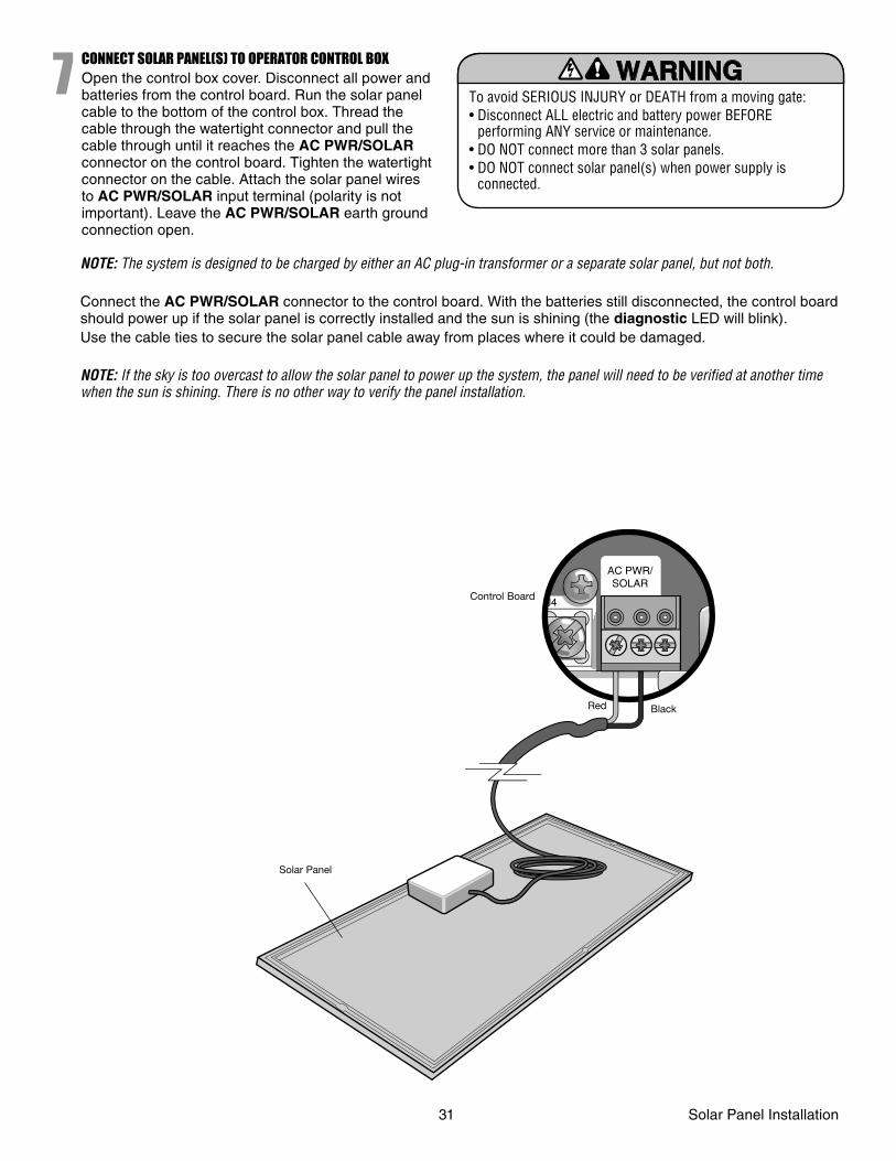
7CONNECT SOLAR PANEL(S) TO OPERATOR CONTROL BOXOpen the control box cover. Disconnect all power and batteries from the control board. Run the solar panel cable to the bottom of the control box. Thread the cable through the watertight connector and pull the cable through until it reaches the AC PWR/SOLAR connector on the control board. Tighten the watertight connector on the cable. Attach the solar panel wires to AC PWR/SOLAR input terminal (polarity is not important). Leave the AC PWR/SOLAR earth ground connection open.
To avoid SERIOUS INJURY or DEATH from a moving gate:• Disconnect ALL electric and battery power BEFORE
performing ANY service or maintenance.• DO NOT connect more than 3 solar panels.• DO NOT connect solar panel(s) when power supply is
connected.
NOTE: The system is designed to be charged by either an AC plug-in transformer or a separate solar panel, but not both.
Connect the AC PWR/SOLAR connector to the control board. With the batteries still disconnected, the control board should power up if the solar panel is correctly installed and the sun is shining (the diagnostic LED will blink). Use the cable ties to secure the solar panel cable away from places where it could be damaged.
NOTE: If the sky is too overcast to allow the solar panel to power up the system, the panel will need to be verifi ed at another time when the sun is shining. There is no other way to verify the panel installation.
AC PWR/SOLAR
J4Control Board
BlackRed
Solar Panel
31 Solar Panel Installation
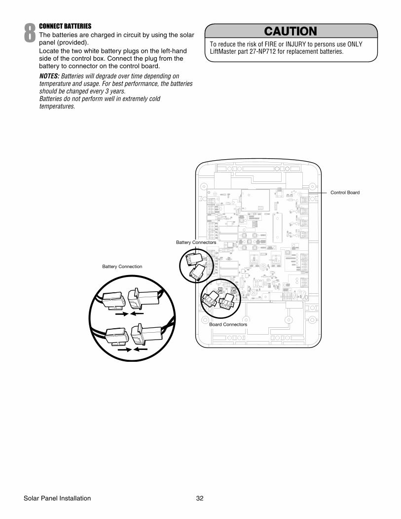
8CONNECT BATTERIESThe batteries are charged in circuit by using the solar panel (provided).Locate the two white battery plugs on the left-hand side of the control box. Connect the plug from the battery to connector on the control board.
NOTES: Batteries will degrade over time depending on temperature and usage. For best performance, the batteries should be changed every 3 years.Batteries do not perform well in extremely cold temperatures.
To reduce the risk of FIRE or INJURY to persons use ONLY LiftMaster part 27-NP712 for replacement batteries.
1818R93R93
L1L1
D42D42
K2
K2
D1D1Ø
Z22
Z22
P1
P1
F2
F2
MO
V1
MO
V1
D1
D1
Q12
Q12
U4U4
OFFOFF MAXMAX
OPENOPEN
SINGLE BUTTONSINGLE BUTTON
RESETRESET
STOPSTOP
CHGRCHGROVLDOVLD
COMCOM
COMCOM
D129D129
Z4Z4
U3
U3 D2D2
D44D44
C11
C11
C13C13
C12
C12
D16
D16
F9
F9
R1R1Ø1R1R1ØØØØ
K1
K1
Q22Q22
F3F3
K3
K3
K4
K4
R196R196
F1F1
Z12Z12
GATE 2GATE 2
GATE 1GATE 1
MAGRMAGR
SOLSOL
GRGR
WHWH
YLYL
BLBL
RDRD
BRBR
GRGR
WHWH
YLYL
BLBL
RDRD
BRBR
F7F7
24V24V
CTRLCTRLOVLDOVLD
TIMERTIMERRUNNINGRUNNING
GATE 2GATE 2
SETSETOPENOPENLIMITLIMIT
SETSETCLOSECLOSELIMITLIMIT
LEARNLEARNLIMITSLIMITS
GATE 1GATE 1
LEARNLEARNXMITTERXMITTER
LOCK /LOCK /
ONON OFFOFF
C69
C69
OFFOFF MAXMAX
J2J2Ø
PWRPWR
AC PWRAC PWR/SOLAR/SOLAR
D8
D8
D4
D4
R9
R9
R329
R329R
27R
27
MO
V2
MO
V2
R4
R4
C2
C2
BIPART DELAYBIPART DELAY
LOCKLOCK
GNDGND
Z1Z1
R1R1
R2R2
K5
K5 F12 F12
Q9
Q9
R9R9Ø
F8F8
Q6
Q6
Q1
Q1
J19J19
R182R182C1C1Ø1Ø1
C75C75
C73C73
C72C72
C71C71
C7C7Ø
C66C66 C65C65
C68
C68
C33
C33
F11
F11
R186
R186
R42R42ØR423R423
J24 J23 3J24 J23 3Ø
A 32V
A 32V
3 3ØA
32VA
32V
J21J21
3030
3030 C64
C64
R22R22U2U2
J18J18
K6K6
JU1
JU1
JU1
JU1
JU2JU2DB1DB1
D36D36
R184R184
Control Board
Battery Connection
Board Connectors
Battery Connectors
Solar Panel Installation 32
PROGRAMMING
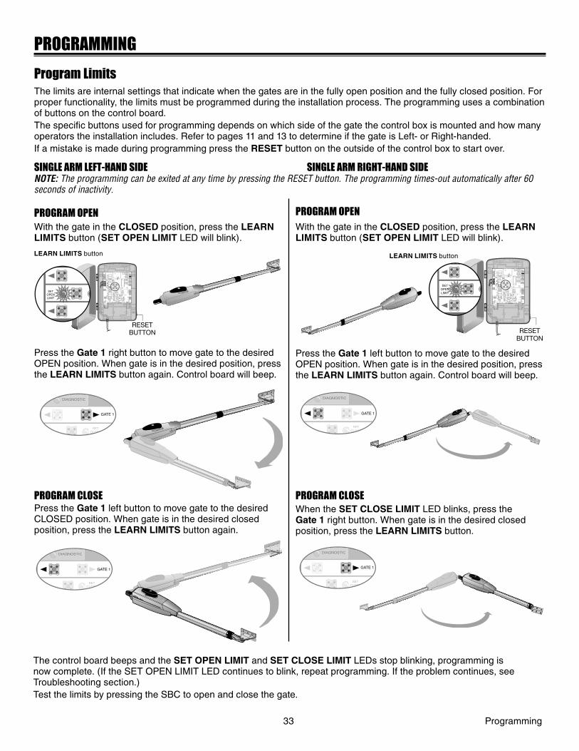
Program LimitsThe limits are internal settings that indicate when the gates are in the fully open position and the fully closed position. For proper functionality, the limits must be programmed during the installation process. The programming uses a combination of buttons on the control board. The specifi c buttons used for programming depends on which side of the gate the control box is mounted and how many operators the installation includes. Refer to pages 11 and 13 to determine if the gate is Left- or Right-handed.If a mistake is made during programming press the RESET button on the outside of the control box to start over.
SINGLE ARM LEFT-HAND SIDE SINGLE ARM RIGHT-HAND SIDENOTE: The programming can be exited at any time by pressing the RESET button. The programming times-out automatically after 60 seconds of inactivity.
33 Programming
Z22
R91
CLOSEEDGE
R94
R92
R93
L1
R1
R2
Z1
K5
K6
K2
F3
10A 32V
D1Ø
OPEN EDGE/OPEN EDGE/
PHOTO
OPENPHOTO
CLOSEPHOTO
R227
R2Ø7
Z2Ø
R223
P1
Z9
Z8
F2
F6
D4
D2
R9
C64JMPR1
R224
U4
CONTROLINPUTS
FORCETIMER TO
CLOSE
OFF MAX
OPEN
SINGLE BUTTON
RESET
STOP
SHADOW
INTERRUPT
CHGROVLD
COM
COM
COM
FUSEOPEN
LOOPINPUTS
POWER
BATT 1BATT 2
F1 20A 32V
R35
D9
Z3
Z4
U3
D1
F5
C11
C13
C12
D15C2R4
R1Ø1
R1ØØ
R9Ø
Q9K1
R196
Q22
D8K3
K4
D21
D22 C4
ACCESSORYOVLD
D6
JMPR2
MOV1MOV2
DB1U2
Z12
24 VAC/SOLARINPUT
GATE 2
ACCESSORYPOWER
MAGLOCK
ALARM
GATE 1
C
C
NC
NO
NO
GRN
WHT
YEL
BLU
RED
BRN
GRN
WHT
YEL
BLU
RED
BRNF4
10A 32V
F7
24V
COMOVLD
TIMERRUNNING
GATE 2
SETOPENLIMIT
SETCLOSELIMIT
LEARNLIMITS
DIAGNOSTIC
GATE 1
J4
LEARNXMITTER
MAGLOCKON OFF
D4
D2
U4
SETOPENLIMIT
RESETBUTTONRESET
BUTTON
LEARN LIMITS button
Press the Gate 1 right button to move gate to the desired OPEN position. When gate is in the desired position, press the LEARN LIMITS button again. Control board will beep.
Press the Gate 1 left button to move gate to the desired CLOSED position. When gate is in the desired closed position, press the LEARN LIMITS button again.
Press the Gate 1 left button to move gate to the desired OPEN position. When gate is in the desired position, press the LEARN LIMITS button again. Control board will beep.
When the SET CLOSE LIMIT LED blinks, press the Gate 1 right button. When gate is in the desired closed position, press the LEARN LIMITS button.
The control board beeps and the SET OPEN LIMIT and SET CLOSE LIMIT LEDs stop blinking, programming is now complete. (If the SET OPEN LIMIT LED continues to blink, repeat programming. If the problem continues, see Troubleshooting section.)Test the limits by pressing the SBC to open and close the gate.
Z22
R91
CLOSE EDGE
R94
R92
R93
L1
R1
R2
Z1
K5
K6
K2
F3
10A 32V
D1Ø
OPEN EDGE/ OPEN EDGE/
PHO T O
OPEN PHO T O
CLOSE PHO T O
R227
R2Ø7
Z2 Ø
R223
P1
Z9
Z8
F2
F6
D4
D2
R9
C64 JMPR1
R224
U4
CONTROL INPUTS
FORCE TIMER TO
CLOSE
OFF MAX
OPEN
SINGLE BUTTON
RESET
STOP
SHADOW
INTERRUPT
CHGR OVLD
COM
COM
COM
FUSE OPEN
LOOP INPUTS
POWER
BATT 1 BATT 2
F1 20A 32V
R35
D9
Z3
Z4
U3
D1
F5
C11
C13
C12
D15 C2 R4
R1Ø1
R1ØØ
R9Ø
Q9 K1
R196
Q22
D8 K3
K4
D21
D22 C4
ACCESSORY OVLD
D6
JMPR2
MOV1 MOV2
DB1 U2
Z12
24 VAC/ SOLAR INPUT
GATE 2
ACCESSORY POWER
MAGLOCK
ALARM
GATE 1
C
C
NC
NO
NO
GRN
WHT
YEL
BLU
RED
BRN
GRN
WHT
YEL
BLU
RED
BRN F4
10A 32V
F7
24V
COM OVLD
TIMER RUNNING
GATE 2
SET OPEN LIMIT
SET CLOSE LIMIT
LEARN LIMITS
DIAGNOSTIC
GATE 1
J4
LEARN XMITTER
MAGLOCK ON OFF
D4
D2
U4
D9
Z3
Z4
U3
D1
D6
OFF SETOPENLIMIT
ENT
RESETBUTTON
SETCLOSE
DIAGNOSTIC
GATE 1
SETCLOSE
DIAGNOSTIC
GATE 1
SETCLOSE
DIAGNOSTIC
GATE 1
SETCLOSE
DIAGNOSTIC
GATE 1
With the gate in the CLOSED position, press the LEARN LIMITS button (SET OPEN LIMIT LED will blink).
With the gate in the CLOSED position, press the LEARN LIMITS button (SET OPEN LIMIT LED will blink).
LEARN LIMITS button
PROGRAM OPEN
PROGRAM CLOSE
PROGRAM OPEN
PROGRAM CLOSE

NOTES:• The gate with the longer travel span (opening) must be set as the primary gate (GATE 1).• If one gate is overlapping the other, the gate that is overlapping must be connected to GATE 1 so it will start moving before the other
gate; gate 2 may need to be closed fi rst if there is overlap or a gate lock is being used.• The programming can be exited at any time by pressing the RESET button. Programming times-out automatically after 60 seconds of
inactivity.
Programming 34
Press the GATE 1 right button to open the left operator. Press the GATE 1 left button to open the right operator.
SETCLOSE
DIAGNOSTIC
GATE 1
FORCE
GATE 2
SETCLOSELIMIT
LELIMIT
SETCLOSE
DIAGNOSTIC
GATE 1
FORCE
GATE 2
SETCLOSELIMIT
LELIMIT
When the SET CLOSE LIMITS LED blinks, press the GATE 2 left button to close the right operator.
When the SET CLOSE LIMITS LED blinks, press the GATE 2 right button to close the left operator.
FORCE
GATE 2
SETCLOSELIMIT
LELIMIT
SETCLOSE
DIAGNOSTIC
GATE 1
SETCLOSE
DIAGNOSTIC
GATE 1
FORCE
GATE 2
SETCLOSELIMIT
LELIMIT
The control board beeps and the SET OPEN LIMIT and SET CLOSE LIMIT LEDs stop blinking, programming is now complete. (If the SET OPEN LIMIT LED continues to blink, repeat programming. If the problem continues, see Troubleshooting section.)Test the limits by pressing the SBC to open and close the gate.
DUAL GATE (LEFT-SIDE PRIMARY OPERATOR) DUAL GATE (RIGHT-SIDE PRIMARY OPERATOR)
Press the GATE 2 right button to move the right operator into the OPEN position.
Press the LEARN LIMITS button. Control board will beep.
Press the GATE 2 left button to move the left operator into the OPEN position.
Press the LEARN LIMITS button. Control board will beep.
Press the GATE 1 left button to close the left operator.
Press the LEARN LIMITS button.
Press the GATE 1 right button to close the right operator.
Press the LEARN LIMITS button.
SETOPENLIMIT
NT
PROGRAM OPEN PROGRAM OPEN
PROGRAM CLOSE PROGRAM CLOSE
With the gate in the CLOSED position, press the LEARN LIMITS button (SET OPEN LIMIT LED will blink).
With the gate in the CLOSED position, press the LEARN LIMITS button (SET OPEN LIMIT LED will blink).
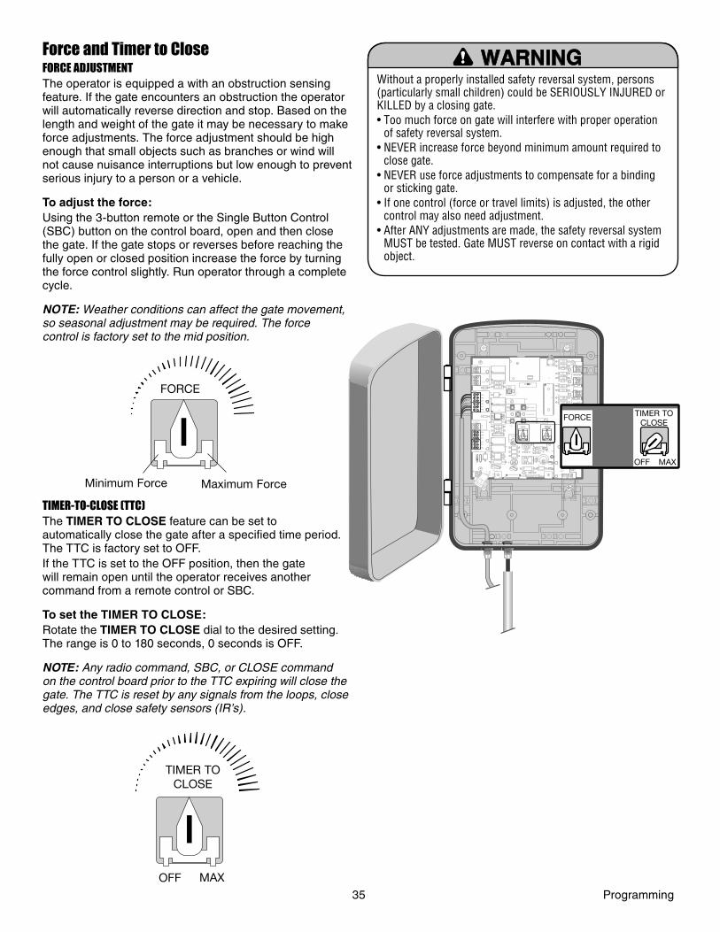
Force and Timer to CloseFORCE ADJUSTMENTThe operator is equipped a with an obstruction sensing feature. If the gate encounters an obstruction the operator will automatically reverse direction and stop. Based on the length and weight of the gate it may be necessary to make force adjustments. The force adjustment should be high enough that small objects such as branches or wind will not cause nuisance interruptions but low enough to prevent serious injury to a person or a vehicle.
To adjust the force:Using the 3-button remote or the Single Button Control (SBC) button on the control board, open and then close the gate. If the gate stops or reverses before reaching the fully open or closed position increase the force by turning the force control slightly. Run operator through a complete cycle.
NOTE: Weather conditions can affect the gate movement, so seasonal adjustment may be required. The force control is factory set to the mid position.
TIMER-TO-CLOSE (TTC)The TIMER TO CLOSE feature can be set to automatically close the gate after a specifi ed time period. The TTC is factory set to OFF. If the TTC is set to the OFF position, then the gate will remain open until the operator receives another command from a remote control or SBC.
To set the TIMER TO CLOSE:Rotate the TIMER TO CLOSE dial to the desired setting. The range is 0 to 180 seconds, 0 seconds is OFF.
NOTE: Any radio command, SBC, or CLOSE command on the control board prior to the TTC expiring will close the gate. The TTC is reset by any signals from the loops, close edges, and close safety sensors (IR’s).
Without a properly installed safety reversal system, persons (particularly small children) could be SERIOUSLY INJURED or KILLED by a closing gate.• Too much force on gate will interfere with proper operation
of safety reversal system.• NEVER increase force beyond minimum amount required to
close gate.• NEVER use force adjustments to compensate for a binding
or sticking gate.• If one control (force or travel limits) is adjusted, the other
control may also need adjustment.• After ANY adjustments are made, the safety reversal system
MUST be tested. Gate MUST reverse on contact with a rigid object.
Z22
R91
CLOSEEDGE
R94
R92
R93
L1
R1
R2
Z1
K5
K6
K2
F3
10A 32V
D1Ø
OPEN EDGE/
PHOTO
OPENPHOTO
CLOSEPHOTO
R227
R2Ø7
Z2Ø
R223
P1
Z9
Z8
F2
F6
D4R9
R224
U4
CONTROLINPUTS
FORCE TIMER TOCLOSE
OFF MAX
OPEN
SINGLE BUTTON
RESET
STOP
SHADOW
INTERRUPT
CHGROVLD
COM
COM
COM
LOOPINPUTS
POWER
BATT 1BATT 2
F1 20A 32V
R35
D9
Z3
Z4
U3
D1
C11
C13
C12
D15C2R4
R1Ø1
R1ØØ
R9Ø
Q9K1
R196
Q22
D8K3
D22 C4
ACCESSORYOVLD
MOV1MOV2
Z12
24 VAC/SOLARINPUT
GATE 2
ACCESSORYPOWER
MAGLOCK
ALARM
GATE 1
C
C
NC
NO
NO
GRN
WHT
YEL
BLU
BLU
RED
BRN
GRN
WHT
YEL
RED
BRN
GRN
WHT
YEL
BLU
RED
BRNF4
10A 32V
F7
24V
COMOVLD
GATE 2
DIAGNOSTIC
GATE 1
GATE 2
J4
LEARNXMITTER
ON
D4
D2
Z9
Z8
FORCE TIMER TO CLOSE
OFF MAX
FORCE
Minimum Force Maximum Force
TIMER TO CLOSE
OFF MAX
35 Programming
Z22
R91
CLOSE EDGE
R94
R92
R93
L1
R1
R2
Z1
K5
K6
K2
F3
10A 32V
D1Ø
OPEN EDGE/
PHO T O
OPEN PHO T O
CLOSE PHO T O
R227
R2Ø7
Z2 Ø
R223
P1
Z9
Z8
F2
F6
D4 R9
R224
U4
CONTROL INPUTS
FORCE TIMER TO CLOSE
OFF MAX
OPEN
SINGLE BUTTON
RESET
STOP
SHADOW
INTERRUPT
CHGR OVLD
COM
COM
COM
LOOP INPUTS
POWER
F1 20A 32V
R35
D9
Z3
Z4
U3
C11
C13
C12
D15 C2 R4
R1Ø1
R1ØØ
R9Ø
Q9 K1
R196
Q22
D8 K3
D22 C4
ACCESSORY OVLD
MOV1 MOV2
Z12
24 VAC/ SOLAR INPUT
GATE 2
ACCESSORY POWER
MAGLOCK
ALARM
GATE 1
C
C
NC
NO
NO
GRN
WHT
YEL
BLU
BLU
RED
BRN
GRN
WHT
YEL
RED
BRN
GRN
WHT
YEL
BLU
RED
BRN F4
10A 32V
F7
24V
COM OVLD
GATE 2
DIAGNOSTIC
GATE 1
GATE 2
J4
LEARN XMITTER
ON
R1
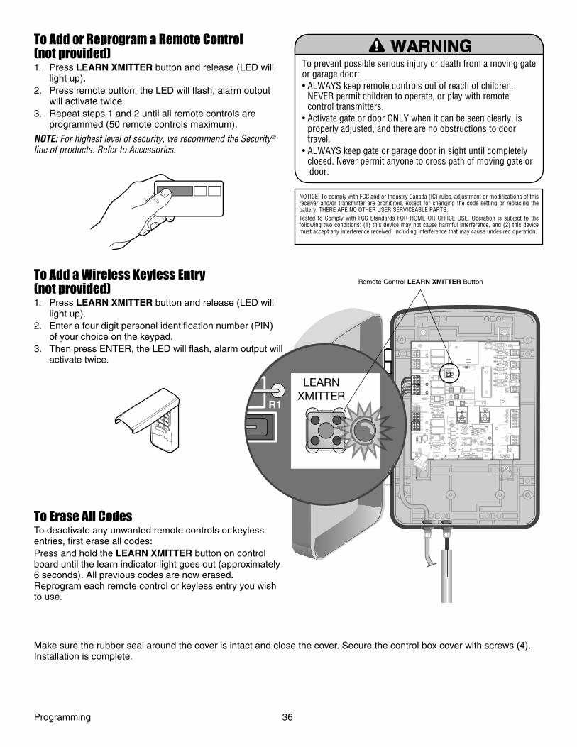
To Add or Reprogram a Remote Control (not provided)1. Press LEARN XMITTER button and release (LED will
light up).2. Press remote button, the LED will fl ash, alarm output
will activate twice.3. Repeat steps 1 and 2 until all remote controls are
programmed (50 remote controls maximum).
NOTE: For highest level of security, we recommend the Security® line of products. Refer to Accessories.
NOTICE: To comply with FCC and or Industry Canada (IC) rules, adjustment or modifications of this receiver and/or transmitter are prohibited, except for changing the code setting or replacing the battery. THERE ARE NO OTHER USER SERVICEABLE PARTS.Tested to Comply with FCC Standards FOR HOME OR OFFICE USE. Operation is subject to the following two conditions: (1) this device may not cause harmful interference, and (2) this device must accept any interference received, including interference that may cause undesired operation.
To prevent possible serious injury or death from a moving gate or garage door:• ALWAYS keep remote controls out of reach of children.
NEVER permit children to operate, or play with remote control transmitters.
• Activate gate or door ONLY when it can be seen clearly, is properly adjusted, and there are no obstructions to door travel.
• ALWAYS keep gate or garage door in sight until completely closed. Never permit anyone to cross path of moving gate or door.
To Add a Wireless Keyless Entry (not provided)1. Press LEARN XMITTER button and release (LED will
light up).2. Enter a four digit personal identifi cation number (PIN)
of your choice on the keypad.3. Then press ENTER, the LED will fl ash, alarm output will
activate twice.
To Erase All CodesTo deactivate any unwanted remote controls or keyless entries, fi rst erase all codes:Press and hold the LEARN XMITTER button on control board until the learn indicator light goes out (approximately 6 seconds). All previous codes are now erased. Reprogram each remote control or keyless entry you wish to use.
Remote Control LEARN XMITTER Button
Programming 36
LEARN XMITTER
Make sure the rubber seal around the cover is intact and close the cover. Secure the control box cover with screws (4). Installation is complete.
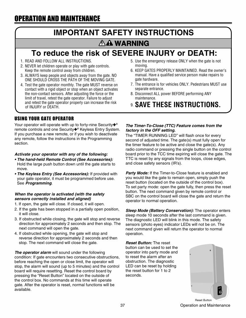
OPERATION AND MAINTENANCE
1. READ AND FOLLOW ALL INSTRUCTIONS. 2. NEVER let children operate or play with gate controls.
Keep the remote control away from children. 3. ALWAYS keep people and objects away from the gate. NO
ONE SHOULD CROSS THE PATH OF THE MOVING GATE. 4. Test the gate operator monthly. The gate MUST reverse on
contact with a rigid object or stop when an object activates the non-contact sensors. After adjusting the force or the limit of travel, retest the gate operator. Failure to adjust and retest the gate operator properly can increase the risk of INJURY or DEATH.
5. Use the emergency release ONLY when the gate is not moving.
6. KEEP GATES PROPERLY MAINTAINED. Read the owner’s manual. Have a qualifi ed service person make repairs to gate hardware.
7. The entrance is for vehicles ONLY. Pedestrians MUST use separate entrance.
8. Disconnect ALL power BEFORE performing ANY maintenance.
9. SAVE THESE INSTRUCTIONS.
ATTENTION
AVERTISSEMENT AVERTISSEMENT
AVERTISSEMENT
WARNING
CAUTION
WARNING
WARNINGWARNING
PRECAUCIÓN ADVERTENCIA
ADVERTENCIAADVERTENCIA
To reduce the risk of SEVERE INJURY or DEATH:
IMPORTANT SAFETY INSTRUCTIONS
USING YOUR GATE OPERATORYour operator will operate with up to forty-nine Security✚® remote controls and one Security✚® Keyless Entry System. If you purchase a new remote, or if you wish to deactivate any remote, follow the instructions in the Programming section.
Activate your operator with any of the following:• The hand-held Remote Control (See Accessories):
Hold the large push button down until the gate starts to move.
• The Keyless Entry (See Accessories): If provided with your gate operator, it must be programmed before use. See Programming.
When the operator is activated (with the safety sensors correctly installed and aligned)1. If open, the gate will close. If closed, it will open.2. If the gate has been stopped in a partially open position,
it will close.3. If obstructed while closing, the gate will stop and reverse
direction for approximately 2 seconds and then stop. The next command will open the gate.
4. If obstructed while opening, the gate will stop and reverse direction for approximately 2 seconds and then stop. The next command will close the gate.
The operator alarm will sound under the following condition: If gate encounters two consecutive obstructions, before reaching the open or close limit, the operator will stop, the alarm will sound (up to 5 minutes) and the control board will require resetting. Reset the control board by pressing the “Reset Button” located on the outside of the control box. No commands at this time will operate gate. After the operator is reset, normal functions will be available.
The Timer-To-Close (TTC) Feature comes from the factory in the OFF setting.The “TIMER RUNNING LED” will fl ash once for every second of adjusted time. The gate(s) must fully open for the timer feature to be active and close the gate(s). Any radio command or pressing the single button on the control board prior to the TCC time expiring will close the gate. The TTC is reset by any signals from the loops, close edges, and close safety sensors (IR’s).
Party Mode: If the Timer-to-Close feature is enabled and you would like the gate to remain open, simply push the reset button (located on the outside of the control box). To set party mode: open the gate fully, then press the reset button. The next command given by remote control or SBC on the control board will close the gate and return the operator to normal operation.
Sleep Mode (Battery Conservation): The operator enters sleep mode 10 seconds after the last command is given. The diagnostic LED will blink in this mode. The safety sensors (photo eyes) indicator LEDs will not be on. The next command given will return the operator to normal operation.
Reset Button: The reset button can be used to set the operator into party mode and to reset the alarm after an obstruction. The diagnostic LED can be reset by holding the reset button for 1 to 2 seconds.
RESET
RESET
37 Operation and MaintenanceReset Button
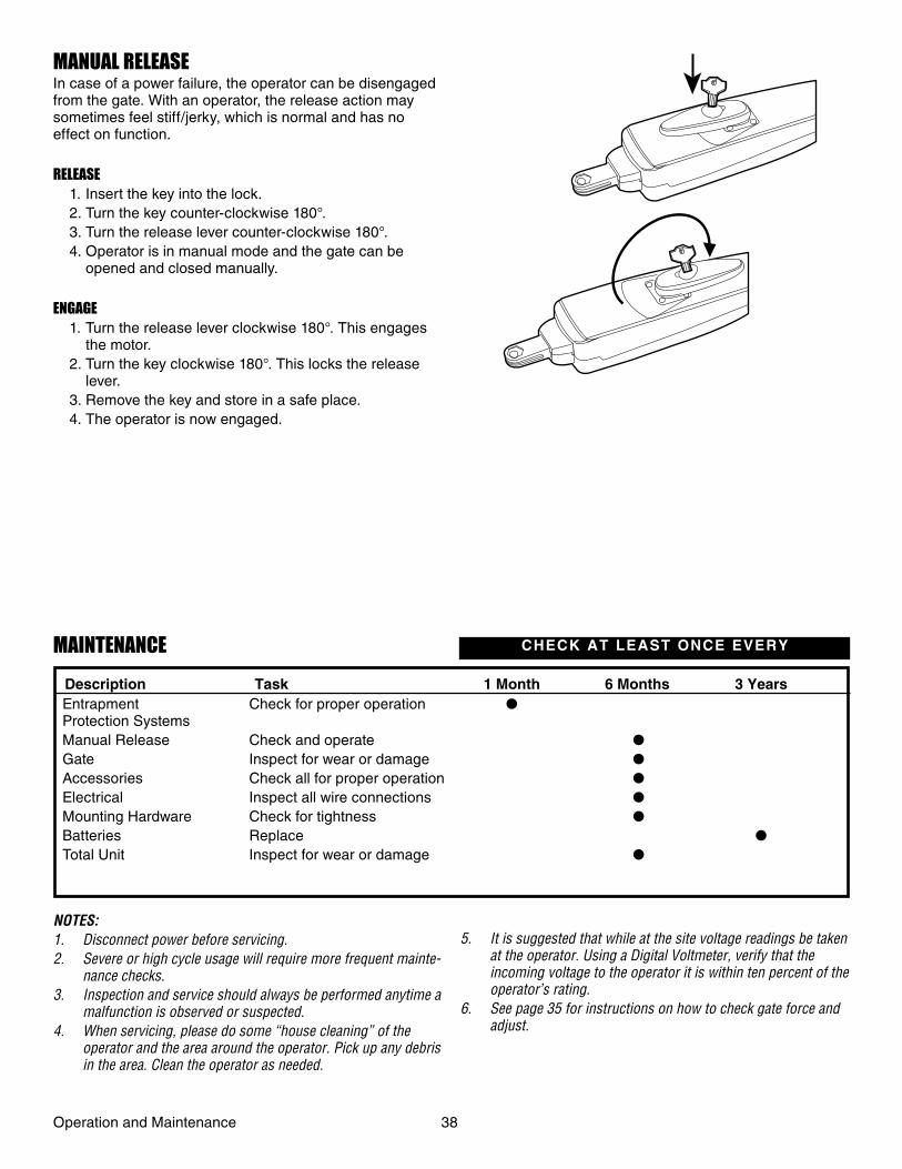
MANUAL RELEASEIn case of a power failure, the operator can be disengaged from the gate. With an operator, the release action may sometimes feel stiff/jerky, which is normal and has no effect on function.
RELEASE 1. Insert the key into the lock. 2. Turn the key counter-clockwise 180°. 3. Turn the release lever counter-clockwise 180°. 4. Operator is in manual mode and the gate can be
opened and closed manually.
ENGAGE 1. Turn the release lever clockwise 180°. This engages
the motor. 2. Turn the key clockwise 180°. This locks the release
lever. 3. Remove the key and store in a safe place. 4. The operator is now engaged.
MAINTENANCE
Check for proper operation ●
Check and operate ●
Inspect for wear or damage ●
Check all for proper operation ●
Inspect all wire connections ●
Check for tightness ●
Replace ●
Inspect for wear or damage ●
EntrapmentProtection SystemsManual ReleaseGateAccessoriesElectricalMounting HardwareBatteriesTotal Unit
CHECK AT LEAST ONCE EVERY
Description Task 1 Month 6 Months 3 Years
NOTES:1. Disconnect power before servicing.2. Severe or high cycle usage will require more frequent mainte-
nance checks.3. Inspection and service should always be performed anytime a
malfunction is observed or suspected.4. When servicing, please do some “house cleaning” of the
operator and the area around the operator. Pick up any debris in the area. Clean the operator as needed.
5. It is suggested that while at the site voltage readings be taken at the operator. Using a Digital Voltmeter, verify that the incoming voltage to the operator it is within ten percent of the operator’s rating.
6. See page 35 for instructions on how to check gate force and adjust.
Operation and Maintenance 38
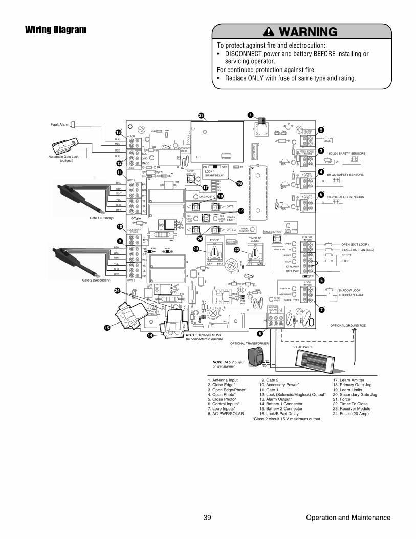
EDGE
EDGE
50-220 SAFETY SENSORS
50-220 SAFETY SENSORS
OR
OPEN (EXIT LOOP )
SINGLE BUTTON (SBC)
RESET
STOP
SHADOW LOOP
INTERRUPT LOOP
50-220 SAFETY SENSORS
CLOSEEDGE
R93
D42
K2
D1Ø
OPEN EDGE/PHOTO
OPENPHOTO
CLOSEPHOTO
Z22
P1
F2
MO
V1
D1
Q12
U4
CONTROLINPUTSFORCE
TIMER TOCLOSE
OFF MAX
OPEN
SINGLE BUTTON
RESET
STOP
SHADOW
INTERRUPT
CHGROVLD
CTRL PWR
CTRL
LOOPINPUTS
D129
Z4
U3 D2
D44
C11
C13
C12
D16
F9
R1Ø1R1ØØ
K1
Q22
F3
K3
K4
R196
F1
Z12
GATE 2
ACCESSORYPOWER
ALARM
GATE 1
MAGR
SOL
GR
WH
YL
BL
RD
BR
GR
WH
YL
BL
RD
BR
F7
12 V
CTRLOVLD
TIMERRUNNING
GATE 2
SETOPENLIMIT
SETCLOSELIMIT
LEARNLIMITS
DIAGNOSTIC
GATE 1
LEARNXMITTER
LOCK /
ON OFF
PWRC69
OFF MAX
J2Ø
PWRSINGLE BUTTON
AC PWR/SOLAR
D8
D4
R9
R329R
27
MO
V2
R4
C2
BIPART DELAY
LOCK
GND
Z1
R1
R2
K5 F12
Q9
R9Ø
F8
Q6
Q1
J19
ACCESSORY0VLD
R182C1Ø1
C75
C73
C72
C71
C7Ø
C66 C65
C68
C33
F11
R186
R42ØR423
J24 J23 3ØA
32V
3ØA
32V
J21
C64
R22U2
J18
K6
JU1
JU2DB1
D36
R184
(optional)
Fault Alarm
Automatic Gate Lock
WHT
GRN
BRN
YEL
BLU
RED
WHT
GRN
BRN
YEL
BLU
REDCTRL PWR
SOLAR PANEL
RED
RED
BLK
BLK
Gate 1 (Primary)
Gate 2 (Secondary)
RED
BLK
OPTIONAL GROUND ROD
OPTIONAL TRANSFORMER
To protect against fire and electrocution: • DISCONNECT power and battery BEFORE installing or servicing operator. For continued protection against fire: • Replace ONLY with fuse of same type and rating.
17. Learn Xmitter 18. Primary Gate Jog19. Learn Limits20. Secondary Gate Jog21. Force 22. Timer To Close 23. Receiver Module24. Fuses (20 Amp)
9. Gate 2 10. Accessory Power* 11. Gate 1 12. Lock (Solenoid/Maglock) Output* 13. Alarm Output* 14. Battery 1 Connector 15. Battery 2 Connector 16. Lock/BiPart Delay
1. Antenna Input2. Close Edge*3. Open Edge/Photo*4. Open Photo*5. Close Photo*6. Control Inputs*7. Loop Inputs*8. AC PWR/SOLAR
15
24
8
7
14 NOTE: Batteries MUST be connected to operate.
NOTE: 14.5 V output on transformer.
*
6*
5*
4*
3*
2*
9
21
19
1716
18
22
20
10
12*
13*
*
11
123
*Class 2 circuit 15 V maximum output
To protect against fi re and electrocution:• DISCONNECT power and battery BEFORE installing or
servicing operator.For continued protection against fi re:• Replace ONLY with fuse of same type and rating.
Wiring Diagram
39 Operation and Maintenance
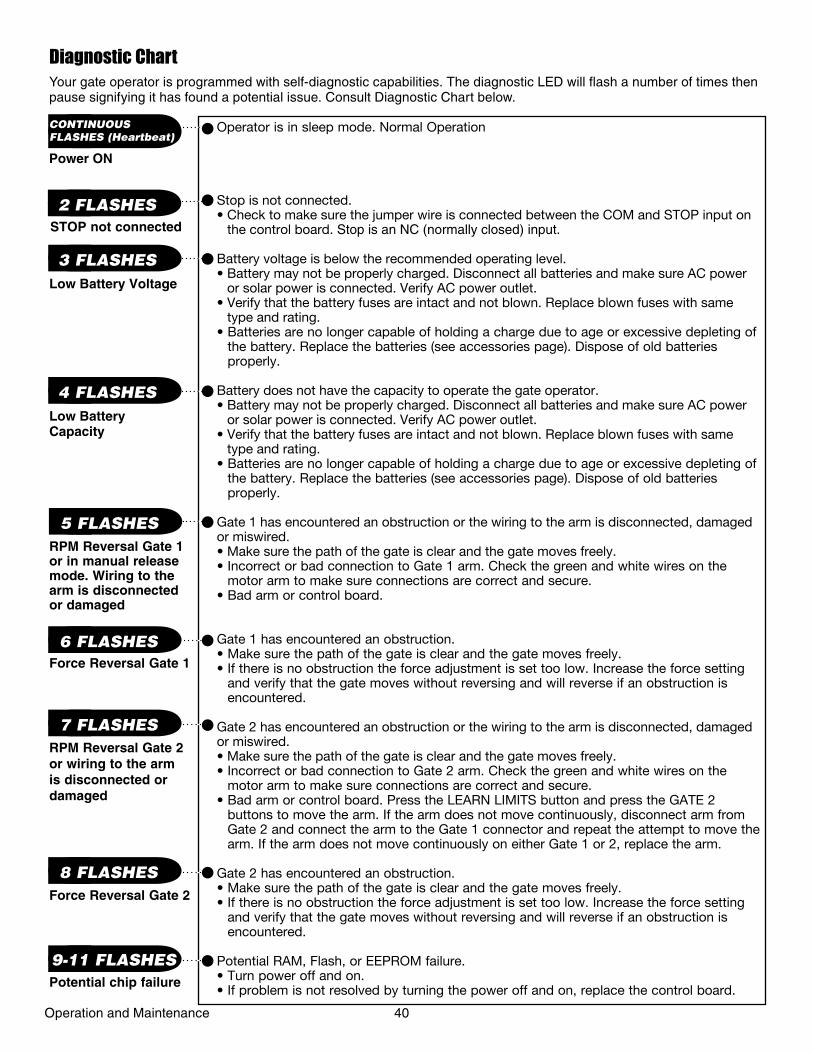
Your gate operator is programmed with self-diagnostic capabilities. The diagnostic LED will fl ash a number of times then pause signifying it has found a potential issue. Consult Diagnostic Chart below.
Diagnostic Chart
Operator is in sleep mode. Normal Operation
Stop is not connected. • Check to make sure the jumper wire is connected between the COM and STOP input on
the control board. Stop is an NC (normally closed) input.
Battery voltage is below the recommended operating level.• Battery may not be properly charged. Disconnect all batteries and make sure AC power
or solar power is connected. Verify AC power outlet.• Verify that the battery fuses are intact and not blown. Replace blown fuses with same
type and rating.• Batteries are no longer capable of holding a charge due to age or excessive depleting of
the battery. Replace the batteries (see accessories page). Dispose of old batteries properly.
Battery does not have the capacity to operate the gate operator.• Battery may not be properly charged. Disconnect all batteries and make sure AC power
or solar power is connected. Verify AC power outlet.• Verify that the battery fuses are intact and not blown. Replace blown fuses with same
type and rating.• Batteries are no longer capable of holding a charge due to age or excessive depleting of
the battery. Replace the batteries (see accessories page). Dispose of old batteries properly.
Gate 1 has encountered an obstruction or the wiring to the arm is disconnected, damaged or miswired.• Make sure the path of the gate is clear and the gate moves freely.• Incorrect or bad connection to Gate 1 arm. Check the green and white wires on the
motor arm to make sure connections are correct and secure.• Bad arm or control board.
Gate 1 has encountered an obstruction. • Make sure the path of the gate is clear and the gate moves freely.• If there is no obstruction the force adjustment is set too low. Increase the force setting
and verify that the gate moves without reversing and will reverse if an obstruction is encountered.
Gate 2 has encountered an obstruction or the wiring to the arm is disconnected, damaged or miswired.• Make sure the path of the gate is clear and the gate moves freely.• Incorrect or bad connection to Gate 2 arm. Check the green and white wires on the
motor arm to make sure connections are correct and secure.• Bad arm or control board. Press the LEARN LIMITS button and press the GATE 2
buttons to move the arm. If the arm does not move continuously, disconnect arm from Gate 2 and connect the arm to the Gate 1 connector and repeat the attempt to move the arm. If the arm does not move continuously on either Gate 1 or 2, replace the arm.
Gate 2 has encountered an obstruction. • Make sure the path of the gate is clear and the gate moves freely.• If there is no obstruction the force adjustment is set too low. Increase the force setting
and verify that the gate moves without reversing and will reverse if an obstruction is encountered.
Potential RAM, Flash, or EEPROM failure.• Turn power off and on. • If problem is not resolved by turning the power off and on, replace the control board.
Force Reversal Gate 1
RPM Reversal Gate 1 or in manual release mode. Wiring to the arm is disconnected or damaged
Low Battery Voltage
STOP not connected
Power ON
2 FLASHES
3 FLASHES
5 FLASHES
6 FLASHES
CONTINUOUSFLASHES (Heartbeat)
RPM Reversal Gate 2 or wiring to the arm is disconnected or damaged
7 FLASHES
Force Reversal Gate 2
8 FLASHES
Potential chip failure
9-11 FLASHES
Low Battery Capacity
4 FLASHES
Operation and Maintenance 40
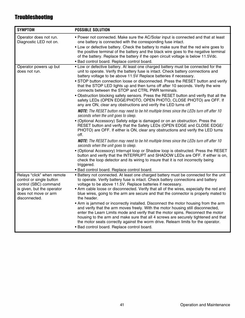
SYMPTOM POSSIBLE SOLUTION
Operator does not run. • Power not connected. Make sure the AC/Solar input is connected and that at least Diagnostic LED not on. one battery is connected with the corresponding fuse intact. • Low or defective battery. Check the battery to make sure that the red wire goes to
the positive terminal of the battery and the black wire goes to the negative terminal of the battery. Replace the battery if the open circuit voltage is below 11.5Vdc.
• Bad control board. Replace control board.Operator powers up but • Low or defective battery. At least one charged battery must be connected for the does not run. unit to operate. Verify the battery fuse is intact. Check battery connections and battery voltage to be above 11.5V Replace batteries if necessary. • STOP button connection loose or disconnected. Press the RESET button and verify
that the STOP LED lights up and then turns off after 10 seconds. Verify the wire connects between the STOP and CTRL PWR terminals.
• Obstruction blocking safety sensors. Press the RESET button and verify that all the safety LEDs (OPEN EDGE/PHOTO, OPEN PHOTO, CLOSE PHOTO) are OFF. If any are ON, clear any obstructions and verify the LED turns off
NOTE: The RESET button may need to be hit multiple times since the LEDs turn off after 10 seconds when the unit goes to sleep. • (Optional Accessory) Safety edge is damaged or on an obstruction. Press the
RESET button and verify that the Safety LEDs (OPEN EDGE and CLOSE EDGE/PHOTO) are OFF. If either is ON, clear any obstructions and verify the LED turns off.
NOTE: The RESET button may need to be hit multiple times since the LEDs turn off after 10 seconds when the unit goes to sleep. • (Optional Accessory) Interrupt loop or Shadow loop is obstructed. Press the RESET
button and verify that the INTERRUPT and SHADOW LEDs are OFF. If either is on, check the loop detector and its wiring to insure that it is not incorrectly being triggered.
• Bad control board. Replace control board.Relays “click” when remote • Battery not connected. At least one charged battery must be connected for the unitcontrol or single button to operate. Verify battery fuse is intact. Check battery connections and batterycontrol (SBC) command voltage to be above 11.5V. Replace batteries if necessary.is given, but the operator • Arm cable loose or disconnected. Verify that all of the wires, especially the red and does not move or arm blue wires, going to the arm are secure and that the connector is properly mated to disconnected. the header. • Arm is jammed or incorrectly installed. Disconnect the motor housing from the arm
and verify that the arm moves freely. With the motor housing still disconnected, enter the Learn Limits mode and verify that the motor spins. Reconnect the motor housing to the arm and make sure that all 4 screws are securely tightened and that the motor seats correctly against the worm drive. Relearn limits for the operator.
• Bad control board. Replace control board.
Troubleshooting
41 Operation and Maintenance
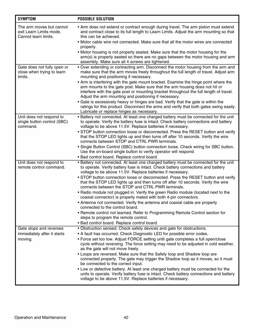
SYMPTOM POSSIBLE SOLUTION
The arm moves but cannot • Arm does not extend or contract enough during travel. The arm piston must extendexit Learn Limits mode. and contract close to its full length to Learn Limits. Adjust the arm mounting so that Cannot learn limits. this can be achieved. • Motor cable wire not connected. Make sure that all the motor wires are connected
properly. • Motor housing is not properly seated. Make sure that the motor housing for the
arm(s) is properly seated so there are no gaps between the motor housing and arm assembly. Make sure all 4 screws are tightened.
Gate does not fully open or • Over extending or contracting arm. Disconnect the motor housing from the arm andclose when trying to learn make sure that the arm moves freely throughout the full length of travel. Adjust armlimits. mounting and positioning if necessary. • Arm is interfering with the gate mount bracket. Examine the hinge point where the
arm mounts to the gate post. Make sure that the arm housing does not hit or interfere with the gate post or mounting bracket throughout the full length of travel. Adjust the arm mounting and positioning if necessary.
• Gate is excessively heavy or hinges are bad. Verify that the gate is within the ratings for this product. Disconnect the arms and verify that both gates swing easily. Lubricate or replace hinges as necessary.
Unit does not respond to • Battery not connected. At least one charged battery must be connected for the unit single button control (SBC) to operate. Verify the battery fuse is intact. Check battery connections and battery command. voltage to be above 11.5V. Replace batteries if necessary. • STOP button connection loose or disconnected. Press the RESET button and verify
that the STOP LED lights up and then turns off after 10 seconds. Verify the wire connects between STOP and CTRL PWR terminals.
• Single Button Control (SBC) button connection loose. Check wiring for SBC button. Use the on-board single button to verify operator will respond.
• Bad control board. Replace control board.Unit does not respond to • Battery not connected. At least one charged battery must be connected for the unit remote control command. to operate. Verify battery fuse is intact. Check battery connections and battery voltage to be above 11.5V. Replace batteries if necessary. • STOP button connection loose or disconnected. Press the RESET button and verify
that the STOP LED lights up and then turns off after 10 seconds. Verify the wire connects between the STOP and CTRL PWR terminals.
• Radio module not plugged in. Verify the green Radio module (located next to the coaxial connector) is properly mated with both 4-pin connectors.
• Antenna not connected. Verify the antenna and coaxial cable are properly connected to the control board.
• Remote control not learned. Refer to Programming Remote Control section for steps to program the remote control.
• Bad control board. Replace control board.Gate stops and reverses • Obstruction sensed. Check safety devices and gate for obstructions. immediately after it starts • A fault has occurred. Check Diagnostic LED for possible error codes. moving. • Force set too low. Adjust FORCE setting until gate completes a full open/close
cycle without reversing. The force setting may need to be adjusted in cold weather, as the gate will not move freely.
• Loops are reversed. Make sure that the Safety loop and Shadow loop are connected properly. The gate may trigger the Shadow loop as it moves, so it must be connected to the correct input.
• Low or defective battery. At least one charged battery must be connected for the units to operate. Verify battery fuse is intact. Check battery connections and battery voltage to be above 11.5V. Replace batteries if necessary.
Operation and Maintenance 42
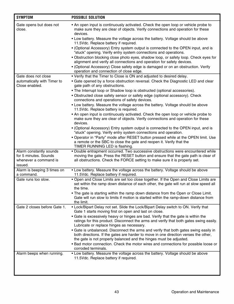
43 Operation and Maintenance
SYMPTOM POSSIBLE SOLUTION
Gate opens but does not • An open input is continuously activated. Check the open loop or vehicle probe to close. make sure they are clear of objects. Verify connections and operation for these devices. • Low battery. Measure the voltage across the battery. Voltage should be above
11.5Vdc. Replace battery if required. • (Optional Accessory) Entry system output is connected to the OPEN input, and is
“stuck” opening. Verify entry system connections and operations. • Obstruction blocking close photo eyes, shadow loop, or safety loop. Check eyes for
alignment and verify all connections and operation for safety devices. • (Optional Accessory) Close safety edge is damaged or on an obstruction. Verify
operation and connection of close edge.Gate does not close • Verify that the Timer to Close is ON and adjusted to desired delay.automatically with Timer to • Gate opened by a force obstruction reversal. Check the Diagnostic LED and clear Close enabled. gate path of any obstructions. • The Interrupt loop or Shadow loop is obstructed (optional accessories). • Obstructed close safety sensor or safety edge (optional accessory). Check
connections and operations of safety devices. • Low battery. Measure the voltage across the battery. Voltage should be above
11.5Vdc. Replace battery is required. • An open input is continuously activated. Check the open loop or vehicle probe to
make sure they are clear of objects. Verify connections and operation for these devices.
• (Optional Accessory) Entry system output is connected to the OPEN input, and is “stuck” opening. Verify entry system connections and operation.
• Operator in “Party” mode after RESET button pressed while at the OPEN limit. Use a remote or the SBC to close the gate and reopen it. Verify that the TIMER RUNNING LED is flashing.
Alarm constantly sounds • Double entrapment occurred. Two successive obstructions were encountered while for 5 minutes. Sounds moving the gate. Press the RESET button and ensure that the gate path is clear of whenever a command is all obstructions. Check the FORCE setting to make sure it is properly set.issued.Alarm is beeping 3 times on • Low battery. Measure the voltage across the battery. Voltage should be above a command. 11.5Vdc. Replace battery if required.Gate runs too slow. • Open and Close Limits are set too close together. If the Open and Close Limits are
set within the ramp down distance of each other, the gate will run at slow speed all the time.
• The gate is starting within the ramp down distance from the Open or Close Limit. Gate will run slow to limits if motion is started within the ramp-down distance from the limit.
Gate 2 closes before Gate 1. • Lock/Bipart Delay not set. Slide the Lock/Bipart Delay switch to ON. Verify that Gate 1 starts moving first on open and last on close.
• Gate is excessively heavy or hinges are bad. Verify that the gate is within the ratings for this product. Disconnect the arms and verify that both gates swing easily. Lubricate or replace hinges as necessary.
• Gate is unbalanced. Disconnect the arms and verify that both gates swing easily in both directions. If the gates are harder to move in one direction verses the other, the gate is not properly balanced and the hinges must be adjusted.
• Bad motor connection. Check the motor wires and connections for possible loose or corroded terminals.
Alarm beeps when running. • Low battery. Measure the voltage across the battery. Voltage should be above 11.5Vdc. Replace battery if required.
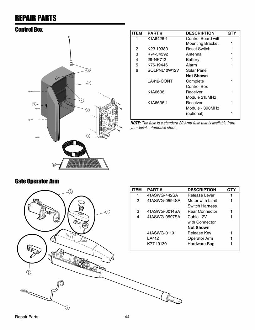
3
54
2
1
6
7
REPAIR PARTS
Control BoxITEM PART # DESCRIPTION QTY 1 K1A6426-1 Control Board with
Mounting Bracket 1 2 K23-19380 Reset Switch 1 3 K74-34392 Antenna 1 4 29-NP712 Battery 1 5 K76-19446 Alarm 1 6 SOLPNL10W12V Solar Panel Not Shown LA412-CONT Complete 1 Control Box K1A6636 Receiver 1 Module 315MHz K1A6636-1 Receiver 1 Module - 390MHz (optional) 1
NOTE: The fuse is a standard 20 Amp fuse that is available from your local automotive store.
Repair Parts 44
Gate Operator Arm
1
2
3
4
ITEM PART # DESCRIPTION QTY 1 41ASWG-442SA Release Lever 1 2 41ASWG-0594SA Motor with Limit 1 Switch Harness 3 41ASWG-0014SA Rear Connector 1 4 41ASWG-0597SA Cable 12V 1 with Connector Not Shown 41ASWG-0119 Release Key 1 LA412 Operator Arm 1 K77-19130 Hardware Bag 1
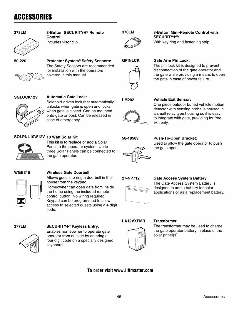
ACCESSORIES
3-Button SECURITY✚® Remote Control:Includes visor clip.
Protector System® Safety Sensors:The Safety Sensors are recommendedfor installation with the operators covered in this manual.
Automatic Gate Lock:Solenoid-driven lock that automatically unlocks when gate is open and locks when gate is closed. Can be mounted onto gate or post. Can be released in case of emergency.
10 Watt Solar KitThis kit is to replace or add a Solar Panel to the operator system. Up to three Solar Panels can be connected to the gate operator.
Wireless Gate DoorbellAllows guests to ring a doorbell in the house from the keypad.Homeowner can open gate from inside the home using the included remote control button. No wiring required. Keypad can be programmed to allow access to selected guests using a 4 digit code.
SECURITY✚® Keyless Entry:Enables homeowner to operate gate operator from outside by entering a four digit code on a specially designed keyboard.
373LM
50-220
SGLOCK12V
SOLPNL10W12V
WGB315
377LM
370LM 3-Button Mini-Remote Control with SECURITY✚®:With key ring and fastening strip.
GPINLCK Gate Arm Pin Lock:The pin lock kit is designed to prevent disconnection of the gate operator and the gate while providing a means to open the gate in case of power failure.
LM202 Vehicle Exit Sensor:One piece outdoor buried vehicle motion detector with sensing probe is housed in a small relay type housing so it is easy to integrate with gate, providing for free exit only.
50-19503 Push-To-Open Bracket:Used to allow the gate operator to push the gate open.
27-NP712 Gate Access System BatteryThe Gate Access System Battery is designed to add a battery for solar applications or as a replacement battery.
45 Accessories
OPEN
TOPRESS
RING
OPEN
CLOSE
OPEN
TOPRESS
RING
7
OPEN
CLOSE
OPEN
TOPRESS
RING
OPEN
CLOSE
OPEN
TOPRESS
RING
OPEN
CLOSE
OPEN
TOPRESS
RING
OPEN
CLOSE
OPEN
TOPRESS
RING
OPEN
CLOSE
OPEN
TOPRESS
RING
OPEN
CLOSE
OPEN
TOPRESS
RING
OPEN
CLOSE
OPEN
TOPRESS
RING
OPEN
CLOSE
OPEN
TOPRESS
RING
OPEN
CLOSE
LA12VXFMR TransformerThe transformer may be used to charge the gate operator battery in place of the solar panel(s).
OPEN
TOPRESS
RING
OPEN
CLOSE
To order visit www.liftmaster.com

WARRANTY POLICY
LIFTMASTER ONE YEAR LIMITED WARRANTY
The Chamberlain Group, Inc. warrants to the first retail purchaser of this product, for the structure in which this product is originally installed, that it is free from defect in materials and/or workmanship for a period of ONE year from the date of purchase. The proper operation of this product is dependent on your compliance with the instructions regarding installation, operation, maintenance and testing. Failure to comply strictly with those instructions will void this limited warranty in its entirety.If, during the limited warranty period, this product appears to contain a defect covered by this limited warranty, call 1-800-528-2806, toll free, before dismantling this product. Then send this product, pre-paid and insured, to our service center for warranty repair. You will be advised of shipping instructions when you call. Please include a brief description of the problem and a dated proof-of-purchase receipt with any product returned for warranty repair. Products returned to Seller for warranty repair, which upon receipt by Seller are confirmed to be defective and covered by this limited warranty, will be repaired or replaced (at Seller’s sole option) at no cost to you and returned pre-paid. Defective parts will be repaired or replaced with new or factory-rebuilt parts at Seller’s sole option.ALL IMPLIED WARRANTIES FOR THE PRODUCT, INCLUDING BUT NOT LIMITED TO ANY IMPLIED WARRANTIES OF MERCHANTABILITY AND FITNESS FOR A PARTICULAR PURPOSE, ARE LIMITED IN DURATION TO THE ONE YEAR LIMITED WARRANTY PERIOD SET FORTH ABOVE, AND NO IMPLIED WARRANTIES WILL EXIST OR APPLY AFTER SUCH PERIOD. Some States do not allow limitations on how long an implied warranty lasts, so the above limitation may not apply to you. THIS LIMITED WARRANTY DOES NOT COVER NON-DEFECT DAMAGE, DAMAGE CAUSED BY IMPROPER INSTALLATION, OPERATION OR CARE (INCLUDING, BUT NOT LIMITED TO ABUSE, MISUSE, FAILURE TO PROVIDE REASONABLE AND NECESSARY MAINTENANCE, UNAUTHORIZED REPAIRS OR ANY ALTERATIONS TO THIS PRODUCT), LABOR CHARGES FOR REINSTALLING A REPAIRED OR REPLACED UNIT, OR REPLACEMENT OF BATTERIES.THIS LIMITED WARRANTY DOES NOT COVER ANY PROBLEMS WITH, OR RELATING TO, THE GATE OR GATE HARDWARE, INCLUDING BUT NOT LIMITED TO THE GATE SPRINGS, GATE ROLLERS, GATE ALIGNMENT OR HINGES. THIS LIMITED WARRANTY ALSO DOES NOT COVER ANY PROBLEMS CAUSED BY INTERFERENCE. ANY SERVICE CALL THAT DETERMINES THE PROBLEM HAS BEEN CAUSED BY ANY OF THESE ITEMS COULD RESULT IN A FEE TO YOU. UNDER NO CIRCUMSTANCES SHALL SELLER BE LIABLE FOR CONSEQUENTIAL, INCIDENTAL OR SPECIAL DAMAGES ARISING IN CONNECTION WITH USE, OR INABILITY TO USE, THIS PRODUCT. IN NO EVENT SHALL SELLER’S LIABILITY FOR BREACH OF WARRANTY, BREACH OF CONTRACT, NEGLIGENCE OR STRICT LIABILITY EXCEED THE COST OF THE PRODUCT COVERED HEREBY. NO PERSON IS AUTHORIZED TO ASSUME FOR US ANY OTHER LIABILITY IN CONNECTION WITH THE SALE OF THIS PRODUCT.Some states do not allow the exclusion or limitation of consequential, incidental or special damages, so the above limitation or exclusion may not apply to you. This limited warranty gives you specific legal rights, and you may also have other rights which vary from state to state.
HOW TO ORDER REPAIR PARTS
OUR LARGE SERVICE ORGANIZATIONSPANS AMERICA
FOR INSTALLATION AND SERVICE INFORMATION,CALL OUR TOLL FREE NUMBER
1-800-528-2806
www.liftmaster.com
WHEN ORDERING REPAIR PARTSPLEASE SUPPLY THE FOLLOWING INFORMATION:PART NUMBER DESCRIPTION MODEL NUMBER
ADDRESS ORDER TO:
THE CHAMBERLAIN GROUP, INC.Technical Support Group
6050 S. Country Club RoadTucson, AZ 85706
Warranty 46

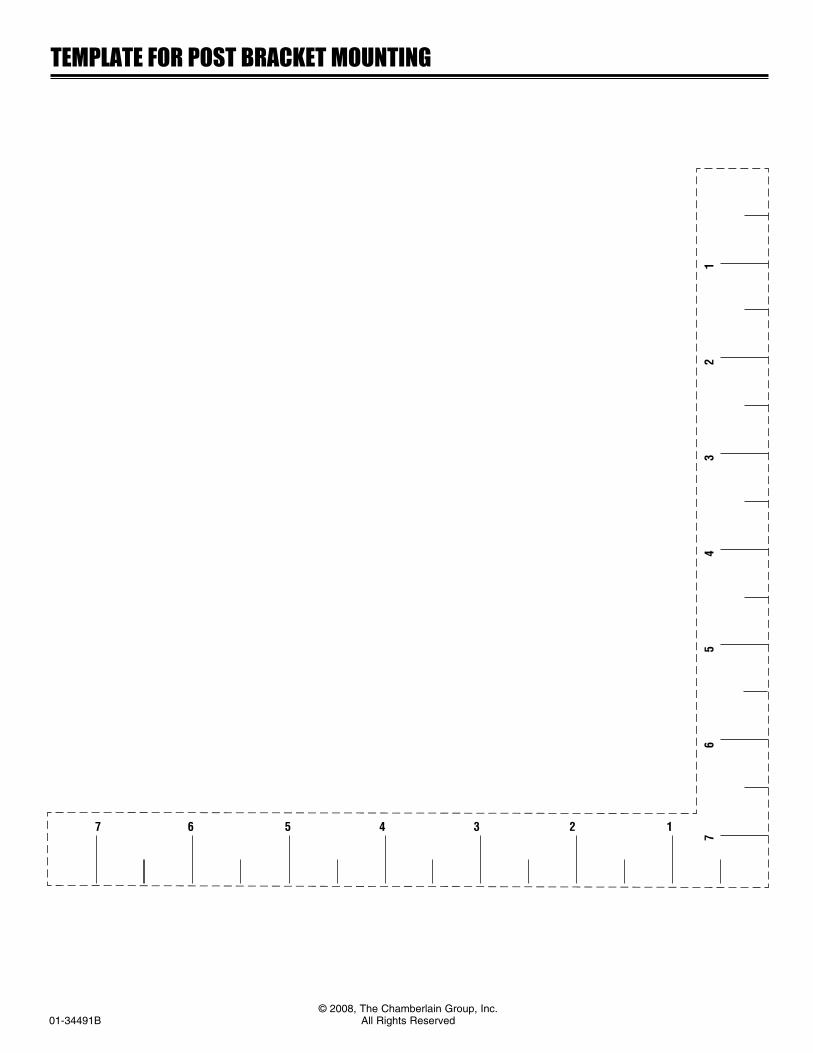
© 2008, The Chamberlain Group, Inc.01-34491B All Rights Reserved
TEMPLATE FOR POST BRACKET MOUNTING
7 6
5 4
3 2
1
7 6 5 4 3 2 1