Embed Size (px)
Citation preview

US0083571 11B2
(12) United States Patent (10) Patent No.: US 8,357,111 B2 Caillouette et al. (45) Date of Patent: Jan. 22, 2013
(54) METHOD AND SYSTEM FOR DESIGNING 3,298.410 A 1/1967 Noboru PATIENTSPECIFIC ORTHOPAEDC 3866, A 8.32 Minishet al.
CaCS C SURGICAL INSTRUMENTS 3,774,244 A 11, 1973 Walker
3,816,855 A 6, 1974 Saleh (75) Inventors: James Caillouette, Newport Beach, CA 3,840,904 A 10, 1974 Eo
(US); Jose F. Guzman, Fort Wayne, IN 3,869,731 A 3/1975 Waugh et al. (US); Jason T. Sherman, Warsaw, IN 3,901.298 A 8/1975 Eby (US) 3,903,549 A 9/1975 Deyerle
(Continued) (73) Assignee: DePuy Products, Inc., Warsaw, IN (US)
FOREIGN PATENT DOCUMENTS (*) Notice: Subject to any disclaimer, the term of this CA 2447694 12/2002
patent is extended or adjusted under 35 (Continued) U.S.C. 154(b) by 1300 days.
(21) Appl. No.: 11/865,013 OTHER PUBLICATIONS Talbot et al., “A home-based pedometer-driven walking program to
(22) Filed: Sep. 30, 2007 increase physical activity in older adults with osteoarthritis of the knee: a preliminary study.” Journal of the American Geriatrics Soci
(65) Prior Publication Data ety, Mar. 2003, vol. 51, No. 3.
US 2009/0088.674 A1 Apr. 2, 2009 (Continued)
51) Int. Cl. (51) o 6/00 (2006.01) Primary Examiner — Patricia Bianco
A6 IB5/103 (2006.01) Assistant Examiner — Brandon L. Jackson A6B 5/17 (2006.01) (74) Attorney, Agent, or Firm — Barnes & Thornburg LLP A6 IB 3/16 (2006.01) A6DF 5/00 (2006.01) (57) ABSTRACT A6IL I5/00 (2006.01) A method and system for designing a patient-specific ortho
(52) U.S. Cl. .............. 602/26:385/12:385/13; 600/301; paedic Surgical instrument includes coupling a knee sleeve to 600/400; 600/587; 600/595; 602/5: 602/6; a leg of the patient. The knee sleeve includes sensors config
602/12: 602/23: 602/75 ured to generate sensor data indicate of the position of the (58) Field of Classification Search ................ 602/5, 12, respective sensor. The method also include determining
602/16, 23, 26; 3.85/12, 13; 600/595,301, angulation data indicative of the angulation of the knee based 600/400, 587 on the sensor data. The angulation data may be indicative of
See application file for complete search history. for example, the ligament laxity of the knee. The method may also include generating a medical image(s) of the knee. The
(56) References Cited design of the patient-specific orthopaedic Surgical instrument is determined based on the angulation data and the medical
U.S. PATENT DOCUMENTS image(s). 2,702,550 A 2, 1955 Rowe 3,229,372 A 1/1966 Quashnocket al. 17 Claims, 11 Drawing Sheets
26
7

US 8,357,111 B2 Page 2
U.S. PATENT DOCUMENTS 5,032,132 A 7/1991 Matsen, III et al. 3,920,022 A 1 1/1975 Pastor 5,035,700 A 7/1991 Kenna 3.941,127 A 3/1976 Froning 5,041,117 A 8/1991 Engelhardt 3,965,950 A 6/1976 MacDonald 5,053,037 A 10/1991 Lackey 3.994,287 A 11, 1976 T 1 5,053,039 A 10, 1991 Hofmann et al. 4,055.862 A i? 1977 AEal 5,060,678 A 10/1991 Bauman et al. 4081866. A 4, 1978 Upshav et al. 38. A 3. tion III 4,085,466 A 4, 1978 Goodfellow et al. W was y, 4,140,161 A 2f1979 Russo et all 5,067,964 A 11/1991 Richmond et al. 4,197,886 A 4/1980 MacDonald 5,084,050 A 1/1992 Draenert 4.311,145 A 1/1982 Esty etal 5,086,401 A 2, 1992 Glassman et al. 4,349,018 A 9, 1982 Chambers 5,092,869 A 3/1992 Waldron 4.373.709 A 2, 1983 Whi 5,098,383 A 3/1992 Hemmy et al. 4.386.609 A 6, 1983 M Itt 5,098.436 A 3, 1992 Ferrante et al. 4400,833 A 8, 1983 E" 5,098,437 A 3, 1992 Kashuba et al. 4.436,684 A 3, 1984 SE 5,100,689 A 3/1992 Goldberg et al. D373895 s 5, 1984 K. te 5,111,987 A 5/1992 Moeinzadeh et al. D274.091 S 5, 1984 R 5,122,144 A 6/1992 Bert et al. 4475549. A 10/1984 na 5,123,906 A 6/1992 Kelman 450.269 A 2, 1985 Bagb 5,129,908 A 7, 1992 Petersen 4,506,393 A 3, 1985 Riy 5,129,909 A 7/1992 Sutherland 4.509.518 A 4/1985 McGarry et al. 5,133,660 A 7/1992 Fenick 4,534.365 A 8, 1985 B 1 5,133,760 A 7, 1992 Petersen et al. 4,545.375 A 10/1985 pita et al. 5,147,365 A 9, 1992 Whitlocket al. 4,549,555 A * 10, 1985 Fraser et al. ... 600,595 5,150,304 A 9/1992 Berchem et al. 4562.598 A 1, 1986 Kr 5,152,744 A 10, 1992 Krause et al. 4.565.19. A 1, 1986 SR, 5,152,778 A 10/1992 Bales, Jr. et al. 4567886 A 2, 1986 SE 5,154,717. A 10/1992 Matsen, III et al. 45.74794 A 3, 1986 Stal 5,171,243 A 12/1992 Kashuba et al. 4,583,554 A * 4, 1986 Mittelman et al. ... 600,587 3:23; A 33: E. s al 4,583,555 A 4, 1986 Malcom et al. ............... 600,595 . . . . p 4,621,630 A 11, 1986 K. 5,174,300 A 12/1992 Bales et al. 4,632. A 12/1986 E. 5,176,684 A 1/1993 Ferrante et al. 4,641,648 A 2, 1987 S. e 5,176,702 A 1/1993 Bales et al. 4,646.739 A 3, 1987 Real 5, 186,174 A 2/1993 Schloendorffet al. 4,662.372 A 5/1987 Sharkanyet al. SE: A SE Rain 4,663,720 A 5, 1987 Duret et al. K-1 4,695.283 A 9, 1987 Aldi 5,197.987 A 3, 1993 Koch et al. 4.703,751. A 11/1987 singer 5,207,680 A 5/1993 Dietz et al. 4,704686 A 1/1987 Aldinger 5,207,692 A 5/1993 Kraus et al. 4,711.233 A 12, 1987 B 5,217,463 A 6, 1993 Mikhail 478,413 A 1, 1988 Non 5,228.459 A 7/1993 Casparietal. 4,718,916 A 1/1988 Morscher 5,234,433 A 8/1993 Bert et al. 4,719.907 A 1, 1988 Banko et all 5,242,448 A 9, 1993 Pettine et al. 4,721.104 A 1/1988 Kaufman et al. 5,258,032 A 1 1/1993 Bertin 4.739.751 A 4, 1988 S 1 5,261,915 A 11/1993 Durlacher et al. 4756.350. A T. 1988 Estal 5,263.498 A 1 1/1993 Casparietal. 4,787,383 A 11/1988 Kenna 33: A E Rui 4,800,874 A 1, 1989 David et al. 5,273.524. A 12/1993 Foxetal 4,822.365 A 4, 1989 Walker et al. 4 - 4,834,080 A 5, 1989 B 5,274.565 A 12/1993 Reuben 4834,757 A 5, 1989 BAigan 5,275,603 A 1/1994 Ferrante et al. 4,838,891. A 6/1989 Branemarket al. 5,282,803 A 2, 1994 Lackey 4,841.975 A 6, 1989 WoO1 5,285,773 A 2f1994 Bonutti et al. 4,846,161 A 7, 1989 in 5,299,288 A 3/1994 Glassman et al. 4,860,735 A 8/1989 Davey et al. 5,300,077. A 4, 1994 Howell 4.888,022 A 12/1989 HuebSch 5,304,181 A 4/1994 Casparietal. 4,893,619. A 1/1990 Daleet al. 3: A 3. N 4,896,663 A 1/1990 Vandewalls 5.314.483. A 5/1994 Goodfellow et al. 4,911,721 A 3/1990 Andergaten 3 et al. 5.330.529 A 6/1994 Pomoa 4,913,163 A 4, 1990 Roger et al. .................. 600,595 5.320,625 A 6, 1994 E. 4,927.422 A 5/1990 Engelhardt 5322505 A 6/1994 Krause etal 4,935,023 A 6, 1990 Whiteside et al. - 44 vs. i. 4.936.852 A 6, 1990 Kent etal 5,342,366 A 8, 1994 Whiteside et al. 4,936,862 A 6, 1990 Witkal 5,342,367 A 8, 1994 Ferrante et al. 4,952,213 A 8/1990 Bowman et al. 5,342,368 A 8/1994 Petersen 4.959.066 A 9, 1990 Dunn etal 5,344.423 A 9, 1994 Dietz et al.
4,961740 A 10/1990 Rayet al. 3. A 2-83. ENy 4,961,954 A 10/1990 Goldberg et al. 5.364.402 A 11/1994 Mumme etal 4,964,865 A 10/1990 Burkhead et al. - w 4.976.737 A 12/1990 Leake 5,368.858 A 11/1994 Hunziker 4,979,949 A 12/1990 Matsen, III et al. 5,370,692 A 12/1994 Finket al.
4985.037 A 1/1991 Petersen 5,382.249 A 1/1995 Fletcher 5,002,579 A 3/1991 Copfet al. 5,383,937 A 1/1995 Mikhail 5,007,912 A 4, 1991 Albrektsson et al. 5,390,683 A 2, 1995 PSharodi 5,007,936 A 4, 1991 Woolson 5,395,376 A 3/1995 Casparietal. 5,015,247 A 5, 1991 Michelson 5,405,395 A 4/1995 Coates 5,030,221 A 7, 1991 Buechel et al. 5,408.409 A 4, 1995 Glassman et al.

US 8,357,111 B2 Page 3
D358,647 S 5, 1995 Cohen et al. 5,716,360 A 2f1998 Baldwin et al. 5,415,662 A 5, 1995 Ferrante et al. 5,720,752 A 2f1998 Elliott et al. 5,417,694 A 5, 1995 Marik et al. 5,722,978 A 3/1998 Jenkins, Jr. 5,423,827 A 6, 1995 Mumme et al. 5,725,376 A 3, 1998 Poirier 5,423,828 A 6, 1995 Benson 5,725,593 A 3, 1998 Caracciolo 5,440,496 A 8, 1995 Andersson et al. 5,733,292 A 3, 1998 Gustillo et al. 5,443,475 A 8, 1995 Auerbach et al. 5,735,277 A 4/1998 Schuster 5,445,639 A 8, 1995 Kuslich et al. 5,748,767 A 5, 1998 Raab 5,445,642 A 8/1995 McNulty et al. 5,749,875 A 5, 1998 Puddu 5.448,489 A 9, 1995 Reuben 5,749,876 A 5/1998 Duvillier et al. 5,452,407 A 9, 1995 Crook 5,755,803 A 5/1998 Haines et al. 5,454,816 A 10/1995 Ashby 5,762,125 A 6/1998 Mastrorio 5,456,268 A 10, 1995 Bonutti 5,768,134 A 6/1998 Swaelens et al. 5,458,645 A 10, 1995 Bertin 5,769,855 A 6/1998 Bertin et al. 5,462.549 A 10, 1995 Glock 5,776.201 A 7/1998 Colleran et al. 5,472.415 A 12/1995 King et al. 5,788,700 A 8, 1998 Morawa et al. 5,474,559 A 12/1995 Bertin et al. 5,791,212 A 8, 1998 Han 5,486, 178 A 1/1996 Hodge 5,792,143 A 8/1998 Samuelson et al. 5.490,854 A 2f1996 Fisher et al. 5,798,924 A 8/1998 Eufinger et al. 5,496,324 A 3, 1996 Barnes 5,799,055 A 8, 1998 Peshkin et al. 5,497,933 A 3, 1996 DeFonzo et al. 5,810,827 A 9, 1998 Haines et al. 5,507,833 A 4, 1996 Bohn 5,810,831 A 9, 1998 D'Antonio 5,510,066 A 4, 1996 Fink et al. 5,817,097 A 10, 1998 Howard et al. 5,514,139 A 5, 1996 Goldstein et al. 5,824,085 A 10/1998 Sahay et al. 5,514,143 A 5, 1996 Bonutti et al. 5,860,980 A 1/1999 Axelson, Jr. et al. 5,514,519 A 5, 1996 Neckers 5,860,981 A 1/1999 Bertin et al. 5,518,680 A 5, 1996 Cima et al. 5,869,170 A 2f1999 Cima et al. 5,520,692 A 5, 1996 Ferrante 5,871,018 A 2/1999 Delp et al. 5,520,694 A 5, 1996 Dance et al. 5,871,493 A 2/1999 Sostrom et al. 5,520,695 A 5, 1996 Luckman 5,876,456 A 3, 1999 Sederholm et al. 5,522,897 A 6/1996 King et al. 5,879,354 A 3, 1999 Haines et al. 5,527,317 A 6/1996 Ashby et al. 5,879,393 A 3, 1999 Whiteside et al. 5,539,649 A 7, 1996 Walsh et al. 5,879,402 A 3, 1999 Lawes et al. 5,540,695 A 7/1996 Levy 5,885,296 A 3, 1999 Masini 5,542,947 A 8/1996 Treacy 5,885,297 A 3/1999 Matsen, III 5,549,683 A 8, 1996 Bonutti 5,885,298 A 3/1999 Herrington et al. 5,554,190 A 9, 1996 Draenert 5,895,389 A 4, 1999 Schenk et al. 5,560,096 A 10/1996 Stephens 5,897,559 A 4/1999 Masini 5,562,674. A 10/1996 Stalcup et al. 5,899,907 A 5/1999 Johnson 5,562,675 A 10/1996 McNulty et al. 5,899,914 A 5/1999 Zirps et al. 5,569,163 A 10, 1996 Francis et al. 5,901,060 A 5/1999 Schall et al. 5,569,261 A 10, 1996 Marik et al. 5,908,424 A 6/1999 Bertin et al. 5,571,110 A 1 1/1996 Matsen, III et al. 5,911,723 A 6/1999 Ashby et al. 5,578,037 A 11/1996 Sanders et al. 5,911,724 A 6, 1999 Wehrli 5,578,039 A 1 1/1996 Vendrely et al. 5,913,874 A 6/1999 Berns et al. 5,586.558 A 12/1996 Riley 5,916,219 A 6/1999 Matsuno et al. 5,593,448 A 1/1997 Dong 5,925,049 A 7/1999 Gustillo et al. 5,595,703 A 1/1997 Swaelens et al. 5,942,370 A 8, 1999 Neckers 5,597,379 A 1/1997 Haines et al. 5,967,777 A 10, 1999 Klein et al. 5,601,563 A 2f1997 Burke et al. 5,976,149 A 11/1999 Masini 5,607,431 A 3, 1997 Dudasik et al. 5,980,526 A 11/1999 Johnson et al. 5,609.603 A 3, 1997 Linden 5,989,261 A 11/1999 Walker et al. 5,620,448 A 4, 1997 Puddu 6,007,537 A 12/1999 Burkinshaw et al. 5,624,444 A 4/1997 Wixon et al. 6,012,456 A 1/2000 Schuerch 5,632,745 A 5, 1997 Schwartz 6,019,767 A 2/2000 Howell 5,634,927 A 6, 1997 Houston et al. 6,022,350 A 2/2000 Ganem 5,643,272 A 7, 1997 Haines et al. 6,024,746 A 2/2000 Katz 5,649,947 A 7, 1997 Auerbach et al. 6,033,415 A 3/2000 Mittelstadt et al. 5,653,714 A 8, 1997 Dietz et al. 6,056,754 A 5, 2000 Haines et al. 5,658.294 A 8, 1997 Sederholm 6,056,756 A 5/2000 Eng et al. 5,662,656 A 9, 1997 White 6,059,831 A 5, 2000 Braslow et al. 5,667,511 A 9/1997 Vendrely et al. 6,063,095 A 5/2000 Wang et al. 5,667,512 A 9, 1997 Johnson 6,066,075 A 5, 2000 Poulton 5,677,107 A 10, 1997 Neckers 6,077,270 A 6/2000 Katz 5,681,316 A 10, 1997 DeCorio et al. 6,077,287 A 6/2000 Taylor et al. 5,681,354 A 10, 1997 Eckhoff 6,080,196 A 6/2000 Bertin 5,682,886 A 1 1/1997 Delp et al. 6,081,577 A 6, 2000 Webber 5,683,397 A 1 1/1997 Vendrely et al. 6,086,593. A 7/2000 Bonutti 5,683,398 A 11/1997 Carls et al. 6,090,122 A 7/2000 Sostrom et al. 5,683,466 A 11, 1997 Vitale 6,096,043 A 8, 2000 Techiera et al. 5,688,279 A 1 1/1997 McNulty et al. 6,099,313 A 8, 2000 Dorken et al. 5,688,280 A 1 1/1997 Booth, Jr. et al. 6,102,850 A 8/2000 Wang et al. 5,690,635 A 1 1/1997 Matsen, III et al. 6,106,529 A 8, 2000 Techiera 5,701,370 A 12, 1997 Muhs et al. ..................... 385/13 6,118,845. A 9, 2000 Simon et al. 5,702.447 A 12, 1997 Walch et al. 6,120,509 A 9, 2000 Wheeler 5,702.460 A 12/1997 Carls et al. 6,120,510 A 9, 2000 Albrektsson et al. 5,702.475 A 12, 1997 Zahedi 6,120,544. A 9, 2000 Grundei et al. 5,704,941 A 1/1998 Jacober et al. 6,126,690 A 10/2000 Ateshian et al. 5,707,350 A 1/1998 Krause et al. 6,139,574 A 10/2000 Vacanti et al.

US 8,357,111 B2 Page 4
6,156,069 6,156,070 6,159,246 6,161,080 6,176,874 6,177,034 6,185.315 6,187,010 6, 195,615 6, 197,064 6,198.794 6,205,411 6,206,927 6,214,051 6,220,122 6,228,121 6,241,735 6,244,141 6,251,143 6,254,604 6,258,127 6,264,698 6,273,891 6,277, 136 6,290,703 6,290,704 6,319,006 6,322,728 6,325,806 6,327.491 6,343.987 6,354,011 6,361,506 6,382,975 6,383,228 6,391,251 6,395,005 6,406,495 6,409,722 6.427,698 D462,767 6,454,811 6,458,135 6.459,948 6.463,351 6,468,280 6,468,289 6,478,799 6,482,209 6,503,255 6,510,334 6,514,259 6,520,964 6,530,958 6,533,737 6,554,837 6,554,838 6,556,008 6,558,391 6,567,681 6,575.980 6,575,982 6,591,581 6,602,259 6,626,945 6,629,999 6,632,225 6,635,073 6,668,941 6,673,077 6,676,662 6,679,917 6,695,848 6,697,664 6,701,174 6,702,821 6,709,462 6,711,431 6,711,432
12, 2000 12, 2000 12, 2000 12, 2000
1, 2001 1, 2001 2, 2001 2, 2001 2, 2001 3, 2001 3, 2001 3, 2001 3, 2001 4, 2001 4, 2001 5, 2001 6, 2001 6, 2001 6, 2001 T/2001 T/2001 T/2001 8, 2001 8, 2001 9, 2001 9, 2001
11, 2001 11, 2001 12, 2001 12, 2001 2, 2002 3, 2002 3, 2002 5, 2002 5, 2002 5, 2002 5, 2002 6, 2002 6, 2002 8, 2002 9, 2002 9, 2002
10, 2002 10, 2002 10, 2002 10, 2002 10, 2002 11, 2002 11, 2002
1, 2003 1, 2003 2, 2003 2, 2003 3, 2003 3, 2003 4, 2003 4, 2003 4, 2003 5/2003 5/2003 6, 2003 6, 2003 T/2003 8, 2003 9, 2003
10, 2003 10, 2003 10, 2003 12, 2003
1, 2004 1, 2004 1, 2004 2, 2004 2, 2004 3, 2004 3, 2004 3, 2004 3, 2004 3, 2004
Amstutz Incavo et al. Mendes et al. Aouni-Ateshian et al. Vacanti et al. Ferrone Schmucker et al. Masini Lysen Haines et al. Peshkin et al. DiGioia, III et al. Fell et al. Badorf et al. Forsell et al. Khalili Marmulla Han Schwartz et al. Howell Schimotzer Lawes et al. Masini Bonutti Ganem Burkinshaw et al. Scherer et al. Brodkin et al. Fox Franklin et al. Hayama et al. Albrecht Saenger et al. Poirier Schimotzer Keicher et al. Lovell Schoch Hoey et al. Yoon Meyer et al. Sherwood et al. Harwin et al. Ateshian et al. Clynch Saenger et al. Bonutti Williamson Engh et al. Albrektsson et al. Schuster et al. Picard et al. Tallarida et al. Cima et al. Brosseau et al. Hauri et al. McGovern et al. Thesen Axelson et al. Lindequist Robie et al. Bonutti Schmieding Masini Simon et al. Serafin, Jr. Sanford et al. Bonutti Phillips et al. Katz Bagga et al. Ek Haines Kienzle, III et al. Krause et al. Bonutti Hanssen Sarin et al. Krause et al.
6,712,824 6,712,856 6,716,249 6,725,077 6,738,657 6,740,092 6,749,638 6,750,653 6,766,878 6,770,078 6,772,026 6,780,190 6,786,930 6,799,066 6,814,735 6,827,723 6,905,514 6,916,324 6,923,817 6,923,831 6,932,842 6,942,475 6,944,518 6,945,976 6,953,480 6,979,299 6,990.220 6,994,549 7,029,477 7,029.479 7,048,741 7,050,877 7,060,074 RE39,301 7,104,997 7,105,026 7,115,131 7,141,053 7,166,063 7,172,597 7,172,599 7,175.435 7,176.466 7,184,814 7,194,295 7,198,628 7,239,908 7,255,702 7,258,701 7,261,719 7,275,218 7,282,054 7,294,133 7,297,164 7,309,339 7,371,260 7,383, 164 7,388,972 7,392,076 7.427,272 7,474,223 7,481,780 7488.324 7,527,631 7,534,263 7,539,243 7,542,791 7,575,602 7,582,091 7,591,821 7,601,155 7,604,639 7,611,516 7,618.451 7,621,915 7.625.409 7,634,119 7,651,501 7,661,170
3, 2004 3, 2004 4, 2004 4, 2004 5, 2004 5, 2004 6, 2004 6, 2004 T/2004 8, 2004 8, 2004 8, 2004 9, 2004 9, 2004
11, 2004 12, 2004 6, 2005 7/2005 8, 2005 8, 2005 8, 2005 9, 2005 9, 2005 9, 2005
10, 2005 12, 2005
1, 2006 2, 2006 4, 2006 4, 2006 5/2006 5/2006 6, 2006 9, 2006 9, 2006 9, 2006
10, 2006 11, 2006 1/2007 2, 2007 2, 2007 2, 2007 2, 2007 2, 2007 3, 2007 4, 2007 7/2007 8, 2007 8, 2007 8, 2007 9, 2007
10, 2007 11/2007 11/2007 12, 2007 5/2008 6, 2008 6, 2008 6, 2008 9, 2008 1/2009 1/2009 2, 2009 5/2009 5/2009 5/2009 6, 2009 8, 2009 9, 2009 9, 2009
10, 2009 10, 2009 11/2009 11/2009 11/2009 12, 2009 12, 2009
1, 2010 2, 2010
Millard et al. Carignan et al. Hyde Balloni et al. Franklin et al. Lombardo et al. Saladino Zou et al. Widmer et al. Bonutti Bradbury et al. Maroney Biscup Steines et al. Zirngiblet al. Carson Carignan et al. Sanford et al. Carson et al. Fell et al. Litschko et al. Ensign et al. Roose Ball et al. Mears et al. Peabody et al. Ellis et al. Brodkin et al. Grimm Tallarida et al. Swanson Iseki et al. Rosa et al. Bertin Lionberger et al. Johnson et al. Enghet al. Rosa et al. Rahman et al. ............. Sanford Steffensmeier et al. Andersson et al. Rousso et al. Lang et al. Vilsmeier Ondrla et al. Alexander et al. Serra et al. Aram et al. Twomey et al. Petrella et al. Steffensmeier et al. Zink et al. Johnson et al. Cusick et al. Malinin Aram et al. Kitson Moctezuma de La Barrera Richard et al. Nycz et al. De Guise et al. Metzger et al. Maroney et al. Burdulis, Jr. et al. Toiflet al. Mire et al. Amirouche et al. Duncan et al. Kelman Peterson Swanson Maroney Berez et al. Fredericket al. Saltzman et al. Tsougarakis et al. Penenberg et al. Goode et al. ................
482/8
. . . . . . . . . . . . 600,595

US 8,357,111 B2 Page 5
7,695.477 B2 4/2010 Creger et al. 2004/0236424 A1 11/2004 Berez et al. 7,704,253 B2 4/2010 Bastian et al. 2004/0243481 Al 12/2004 Bradbury et al. 7,717,956 B2 5/2010 Lang 2004/0249385 A1 12, 2004 Faoro 7,769,422 B2 8/2010 DiSilvestro et al. .......... 600/407 2004/02496.75 A1 12, 2004 Stark et al. 7,780,672 B2 8/2010 Metzger 2004/0254584 A1 12/2004 Sarinet al. 7,796,791 B2 9/2010 Tsougarakis et al. 2004/0260301 Al 12/2004 Lionberger et al. 7,799,077 B2 9/2010 Lang et al. 2005, OO15003 A1 1/2005 Lachner et al. 7,806,896 B1 10/2010 Bonutti 2005, OO15022 A1 1/2005 Richard et al. 7,824, 181 B2 11/2010 Sers 2005/0O273O3 A1 2/2005 Lionberger et al. 7,935,119 B2 5/2011 Ammann et al. 2005/0O27361 A1 2/2005 Reiley 7,963,968 B2 6/2011 Dees, Jr. 2005/OO37320 A1 2, 2005 Poirier 7,967,868 B2 6, 2011 White et al. 2005, 0043835 A1 2/2005 Christensen 7,981,158 B2 7, 2011 Fitz et al. 2005.0043837 A1 2/2005 Rubbert et al.
2001/0005797 A1 6, 2001 Barlow et al. 2005.0049524 A1 3/2005 Lefevre et al. 2001 OO18589 A1 8, 2001 Muller 2005.0049603 A1 3/2005 Calton et al. 2001/002O143 A1 9, 2001 Stark et al. 2005/0059873 A1 3/2005 Glozman et al. 2001/0034554 A1 10/2001 Pappas 2005, OO65628 A1 3/2005 Roose 2001 0037155 A1 11, 2001 Merchant 2005/0070897 A1 3/2005 Petersen 2002, 0007294 A1 1/2002 Bradbury et al. 2005.0075641 A1 4/2005 Singhatat et al. 2002fOO24450 A1 2, 2002 Townsend et al. 2005/OO96535 A1 5/2005 de la Barrera 2002fOO29038 A1 3, 2002 Haines 2005.0113840 A1 5/2005 Metzger et al. 2002fOO29045 A1 3, 2002 Bonutti 2005.0113841 A1 5/2005 Sheldon et al. 2002fOO52606 A1 5, 2002 Bonutti 2005.0113846 A1 5/2005 Carson 2002fOO59049 A1 5/2002 Bradbury et al. 2005, 0119664 A1 6/2005 Carignan et al. 2002/0082741 A1 6/2002 Mazumder et al. 2005, 0131662 A1 6/2005 Ascenzi et al. 2002fO087274 A1 7/2002 Alexander et al. 2005, 0133.955 A1 6/2005 Christensen 2002/0143279 A1 * 10, 2002 Porier et al. .................... 602/16 2005/O137708 A1 6, 2005 Clark 2002fO147415 A1 10, 2002 Martelli 2005. O148843 A1 7/2005 Roose 2002/0173797 A1 11, 2002 Van Zile et al. 2005. O149042 A1 7/2005 Metzger 2002/0183760 A1 12/2002 McGovernet al. 2005/0170311 A1 8, 2005 Tardieu et al. 2002fO198529 A1 12, 2002 Masini 2005/0171545 A1 8, 2005 Walsh et al. 2002fO198531 A1 12, 2002 Millard et al. 2005/017717O A1 8, 2005 Fisher et al. 2003,0009234 A1 1/2003 Treacy et al. 2005/0203536 A1 9/2005 Laffargue et al. 2003, OO11624 A1 1, 2003 Ellis 2005/0203540 A1 9/2005 Broyles 2003, OO18338 A1 1/2003 Axelson et al. 2005/0222573 A1 10, 2005 Branch et al. 2003/0028.196 A1 2/2003 Bonutti 2005/0234461 A1 10, 2005 Burdulis et al. 2003, OO555O1 A1 3, 2003 Fell et al. 2005/0234468 A1 10, 2005 Carson 2003/00555O2 A1 3/2003 Lang et al. 2005/0244239 A1 1 1/2005 Shimp 2003, OO69897 A1 4/2003 Roy et al. 2005.0245934 A1 11/2005 Tuke et al. 2003/010.0906 A1 5, 2003 Rosa et al. 2005.0245936 A1 11/2005 Tuke et al. 2003/01OO907 A1 5, 2003 Rosa et al. 2005/0261697 A1 11/2005 Canonaco et al. 2003.0109784 A1 6, 2003 Loh et al. 2005/0267584 A1 12/2005 Burdulis et al. 2003/O1201.83 A1 6, 2003 Simmons 2005/02731 14 A1 12/2005 Novak 2003. O130665 A1 7/2003 Pinczewski et al. 2005/0283252 A1 12/2005 Coon et al. 2003. O158606 A1 8, 2003 Coon et al. 2005/0283253 A1 12/2005 Coon et al. 2003/0171757 A1 9, 2003 Coon et al. 2006,0004284 A1 1/2006 Grunschlager et al. 2003/0212403 A1 11/2003 Swanson 2006, OO15120 A1 1/2006 Richard et al. 2003/0216669 A1 1 1/2003 Lang et al. 2006, OO3O853 A1 2/2006 Haines 2003/0216741 A1 11/2003 Sanford et al. 2006, OO52725 A1 3/2006 Santilli 2003/0220641 A1 11/2003 Thelen et al. 2006, OO58803 A1 3/2006 Cuckler et al. 2003/0225413 A1 12/2003 Sanford et al. 2006, OO58884 A1 3/2006 Aram et al. 2004/OO392.59 A1 2, 2004 Krause et al. 2006, OO58886 A1 3/2006 Wozencroft 2004/OO39395 A1 2/2004 Coon et al. 2006.0089621 A1 4, 2006 Fard 2004.0068187 A1 4/2004 Krause et al. 2006/0093988 A1 5, 2006 Swaelens et al. 2004/0092932 A1 5, 2004 Aubinet al. 2006/0094951 A1 5, 2006 Dean et al. 2004/00981.33 A1 5/2004 Carignan et al. 2006/0095.049 A1 5/2006 Zannis et al. 2004.0102785 A1 5, 2004 Hodorek et al. 2006/010O832 A1 5, 2006 Bowman 2004.0102852 A1 5/2004 Johnson et al. 2006/011 1722 A1 5, 2006 Bouadi 2004.0102866 A1 5, 2004 Harris et al. 2006.0122616 A1 6/2006 Bennett et al. 2004/0106926 A1 6, 2004 Leitner et al. 2006, O136058 A1 6/2006 Pietrzak 2004/O115586 A1 6/2004 Andreiko et al. 2006, O142657 A1 6/2006 Quaid et al. 2004/O122439 A1 6/2004 Dwyer et al. 2006, O142671 A1 6/2006 Solak 2004.0128026 A1 7/2004 Harris et al. 2006, O142774 A1 6/2006 Metzger 2004/O133276 A1 7/2004 Lang et al. 2006/O142778 A1 6/2006 Dees 2004/O138670 A1 7/2004 Metzger 2006, O155380 A1 7/2006 Clemow et al. 2004/O138754 A1 7/2004 Lang et al. 2006, O161167 A1 7/2006 Myers et al. 2004.0143336 A1 7/2004 Burkinshaw 2006, O184177 A1 8, 2006 Echeverri 2004/O147927 A1 7/2004 Tsougarakis et al. 2006, O190086 A1 8, 2006 Clemow et al. 2004/O153079 A1 8/2004 Tsougarakis et al. 2006, O195198 A1 8, 2006 James 2004/O153087 A1 8, 2004 Sanford et al. 2006/0204932 A1 9/2006 Haymann et al. 2004/O158254 A1 8/2004 Eisermann 2006/0210644 A1 9, 2006 Levin 2004O162619 A1 8/2004 Blaylocket al. 2006/0235421 A1 10, 2006 Rosa et al. 2004O167390 A1 8/2004 Alexander et al. 2006/0245627 A1 1 1/2006 Nagamune 2004/0171924 A1 9, 2004 Mire et al. 2006/0271058 A1 11/2006 Ashton et al. 2004/0172137 A1 9/2004 Blaylocket al. 2006/0276796 Al 12/2006 Creger et al. 2004/O181144 A1 9/2004 Cinquin et al. 2006/0276,797 A1 12/2006 Botimer 2004/O185422 A1 9, 2004 Orth et al. 2006/0287733 A1 12/2006 Bonutti 2004/0204760 A1 10, 2004 Fitz et al. 2007/OOO6887 A1 1, 2007 Frank 2004/0220583 Al 1 1/2004 Pieczynski et al. 2007, OO15995 A1 1/2007 Lang et al.

US 8,357,111 B2 Page 6
2007, OO16209 A1 1/2007 Ammann et al. 2008/0319448 A1 12/2008 Lavallee et al. 2007/0027680 A1 2/2007 Ashley et al. 2009 OO12526 A1 1/2009 Fletcher 2007/0059665 A1 3/2007 Orentlicher et al. 2009 OO18546 A1 1/2009 Daley 2007/0066917 A1 3/2007 Hodorek et al. 2009.0024131 A1 1/2009 Metzger et al. 2007/0O83209 A1 4/2007 Schenberger et al. 2009.0043556 A1 2/2009 Axelson et al. 2007, 0083214 A1 4/2007 Duncan et al. 2009/0076371 A1 3/2009 Lang et al. 2007, 0083266 A1 4/2007 Lang 2009/0076512 A1 3/2009 Ammann et al. 2007/010O258 A1 5, 2007 Shoham et al. 2009/008277O A1 3/2009 Worner et al. 2007, 0100462 A1 5/2007 Lang et al. 2009/0087276 A1 4/2009 Rose 2007/01 18055 A1 5, 2007 McCombs 2009,0088.674 A1 4/2009 Caillouette et al. 2007, 0118243 A1 5, 2007 Schroeder et al. 2009, OO88753 A1 4/2009 Aram et al. 2007. O156066 A1 7/2007 McGinley et al. 2009, OO88754 A1 4/2009 Aker et al. 2007/0162039 A1 7/2007 Wozencroft 2009, OO88755 A1 4/2009 Aker et al. 2007/017394.6 A1 7, 2007 Bonutti 2009, OO88758 A1 4/2009 Bennett 2007/O185498 A2 8, 2007 Lavallee 2009, OO88759 A1 4/2009 Aram et al. 2007/O198O22 A1 8/2007 Lang et al. 2009 OO88760 A1 4/2009 Aram et al. 2007/0203430 A1 8/2007 Lang et al. 2009 OO88761 A1 4/2009 Roose et al. 2007/02O3605 A1 8, 2007 Melton et al. 2009 OO88763 A1 4/2009 Aram et al. 2007/0213738 A1 9, 2007 Martin et al. 2009.0089.034 A1 4/2009 Penney et al. 2007/0219639 A1 9, 2007 Otto et al. 2009.0089081 A1 4/2009 Haddad 2007/0225719 A1 9, 2007 Stone et al. 2009/009381.6 A1 4/2009 Roose et al. 2007/0233121 A1 10, 2007 Carson et al. 2009, OO99567 A1 4/2009 Zajac 2007/0233.136 A1 10, 2007 Wozencroft 2009/O105837 A1 4/2009 Lafosse et al. 2007/0233140 A1 10/2007 Metzger et al. 2009.0118736 A1 5/2009 Kreuzer 2007/0233141 A1 10, 2007 Park et al. 2009,013 1941 A1 5, 2009 Park et al. 2007/02332.69 A1 10, 2007 Steines et al. 2009,013 1942 A1 5/2009 Aker et al. 2007/0233272 A1 10/2007 Boyce et al. 2009, O138020 A1 5, 2009 Park et al. 2007/0238069 A1 10, 2007 LOVald et al. 2009, O149965 A1 6/2009 Quaid 2007/0239282 A1 10/2007 Caylor et al. 2009/O149977 A1 6/2009 Schendel 2007/0239481 A1 10, 2007 DiSilveStro et al. 2009. O151736 A1 6/2009 Belcher et al. 2007/0250169 A1 10/2007 Lang 2009. O157083 A1 6/2009 Park et al. 2007,0253617 A1 11, 2007 Arata et al. 2009, O163922 A1 6/2009 Meridew et al. 2007,025.5288 A1 11, 2007 Mahfouz et al. 2009, O163923 A1 6/2009 Flett et al. 2007/0255412 A1 1 1/2007 Haja et al. 2009, O164024 A1 6/2009 Rudan et al. 2007/0276224 A1 1 1/2007 Lang et al. 2009/O1871.93 A1 7/2009 Maroney et al. 2007/0276400 A1 11, 2007 Moore et al. 2009/0209884 A1 8, 2009 Van Vorhis et al. 2007/02765O1 A1 11/2007 Betz et al. 2009,0209961 A1 8/2009 Ferrante et al. 2007/0282451 A1 12/2007 Metzger et al. 2009, 0222014 A1 9/2009 Bojarski et al. 2007/0288030 Al 12/2007 Metzger et al. 2009/0222015 A1 9, 2009 Park et al. 2008.OOO9952 A1 1/2008 Hodge 2009, 022201.6 A1 9, 2009 Park et al. 2008.0015602 A1 1/2008 Axelson 2009/0228O16 A1 9, 2009 Alvarez et al. 2008.0015605 A1 1/2008 Collazo 2009, 0234360 A1 9, 2009 Alexander 2008, OO156O7 A1 1/2008 D’Alessio et al. 2009/0248044 A1 10, 2009 Amiot et al. 2008, 0021299 A1 1/2008 Meulink 2009,0254093 A1 10, 2009 White et al. 2008/0021567 A1 1/2008 Meulink et al. 2009,0254367 A1 10, 2009 Belcher et al. 2008.OO27563 A1 1/2008 Johnson et al. 2009,0270868 A1 10, 2009 Park et al. 2008/0051910 A1 2/2008 Kammerzell et al. 2009/0274350 A1 11/2009 Pavlovskaia et al. 2008/0058945 A1 3/2008 Hajaj et al. 2009/0306676 Al 12/2009 Lang et al. 2008.OO58947 A1 3/2008 Earl et al. 2009/0307893 Al 12/2009 Burdulis, Jr. et al. 2008.0114370 A1 5, 2008 Schoenefeld et al. 2009/0318836 A1 12/2009 Stone et al. 2008. O140209 A1 6/2008 Iannotti et al. 2010, OO16947 A1 1/2010 Dobak et al. 2008. O146969 A1 6, 2008 Kurtz 2010, OO16984 A1 1/2010 Trabish 2008/O147072 A1 6, 2008 Park et al. 2010, OO16986 A1 1/2010 Trabish 2008.0161815 A1 7/2008 Schoenefeld et al. 2010, 0023015 A1 1, 2010 Park 2008/O172125 A1 T/2008 Ek 2010.003O231 A1 2/2010 Revie et al. 2008/O183177 A1 7/2008 Fox et al. 2010.0042105 A1 2/2010 Park et al. 2008/O195099 A1 8, 2008 Minas 2010.0049195 A1 2/2010 Park et al. 2008/O195107 A1 8, 2008 Cuckler et al. 2010/0076439 A1 3/2010 Hatch 2008. O195216 A1 8/2008 Philipp 2010/0076505 A1 3/2010 Borja 2008, 0208.200 A1 8, 2008 Crofford 2010/0076563 A1 3/2010 Otto et al. 2008/0215059 A1 9/2008 Carignan et al. 2010/0076571 A1 3/2010 Hatch 2008/0228189 A1 9, 2008 Fox et al. 2010.0082034 A1 4/2010 Remia 2008/0234664 A1 9/2008 May et al. 2010.0082035 A1 4/2010 Keefer 2008/0234683 A1 9/2008 May 2010, 0087829 A1 4/2010 Metzger et al. 2008/0234685 A1 9/2008 Gjerde 2010/0094295 A1 4/2010 Schnieders et al. 2008/0234833 A1 9, 2008 Bandoh et al. 2010/0105011 A1 4/2010 Karkar et al. 2008/0243127 A1 10/2008 Lang et al. 2010, 0121335 A1 5/2010 Penenberg et al. 2008/0257363 A1 10, 2008 Schoenefeld et al. 2010.0137869 A1 6/2010 Borja et al. 2008, O262624 A1 10, 2008 White et al. 2010.0137924 A1 6, 2010 Tuke et al. 2008/026.9906 A1 10, 2008 Iannotti et al. 2010, 0145343 A1 6/2010 Johnson et al. 2008/0275452 A1 1 1/2008 Lang et al. 2010, 0145344 A1 6/2010 Jordan et al. 2008/0281328 A1 1 1/2008 Lang et al. 2010. O152782 A1 6, 2010 Stone et al. 2008/0281329 A1 11, 2008 Fitz et al. 2010, 0160917 A1 6, 2010 Fitz et al. 2008/0281426 A1 11, 2008 Fitz et al. 2010, 0168754 A1 7/2010 Fitz et al. 2008/0287954 A1 11, 2008 Kunz et al. 2010, 0168857 A1 7, 2010 Hatch 2008/0294266 A1 1 1/2008 Steinberg 2010.0185202 A1 7/2010 Lester et al. 2008/0300600 A1 12/2008 Guelat et al. 2010, 0191244 A1 7/2010 White et al. 2008/0306558 A1 12, 2008 Hakki 2010, 0212138 A1 8, 2010 Carroll et al. 2008/0312659 A1 12/2008 Metzger et al. 2010, 0217109 A1 8, 2010 Belcher

US 8,357,111 B2 Page 7
2010, 0217270 A1 8, 2010 Polinski et al. EP 1938749 A2 7, 2008 2010, 0217.338 A1 8, 2010 Carroll et al. EP 1669033 B1 2/2009 2010/0228257 A1 9, 2010 Bonutti FR 1111677 3, 1956 2010/0249657 A1 9/2010 Nycz et al. FR 2429582 A1 1, 1980 2010/0249796 A1 9/2010 Nycz FR 265922.6 A1 9, 1991 2010, O262150 A1 10, 2010 Lian FR 2721 195 A1 12/1995 2010/0274253 A1 10, 2010 Ure FR 276891.6 A1 4, 1999 2010/0281678 Al 1 1/2010 Burdulis, Jr. et al. FR 2819168 A1 7, 2002 2010/0286700 A1 11/2010 Snider et al. GB 2094590 A 9, 1982 2010/0292743 Al 1 1/2010 Singhal et al. GB 2197790. A 6, 1988 2010/0305574 A1 12, 2010 Fitz et al. GB 2426200. A 11 2006 2010/0324692 Al 12/2010 Uthgenannt et al. GB 243.7003 A 10/2007 2011/0004317 A1 1/2011 Hacking et al. GB 2442441. A 4, 2008 2011/0015636 A1 1/2011 Katrana et al. JP 59157715. A 9, 1984 2011/0015639 A1 1/2011 Metzger et al. JP 60231208 A 11, 1985 2011/0029091 A1 2/2011 Bojarski et al. KR 2005OO72500 A T 2005 2011/00291 16 A1 2/2011 Jordan et al. KR 20050.084024. A 8, 2005 2011/0046735 A1 2/2011 Metzger et al. RU 2083179 C1 7, 1997 2011/0054478 A1 3f2011 Vanasse et al. RU 2113182 C1 6, 1998 2011/0066193 A1 3/2011 Lang et al. RU 2125835 C1 2/1999 2011, 0071528 A1 3, 2011 Carson RU 21382.23 C1 9, 1999 2011, 0071529 A1 3, 2011 Carson RU 2175534 C2 11/2001 2011, 0071530 A1 3, 2011 Carson RU 2187975 C1 8/2002 2011, 0071532 A1 3, 2011 Carson TW I231755 5, 2005 2011/007 1533 A1 3/2011 Metzger et al. WO 880784.0 A1 10, 1988 2011/0092804 A1 4/2011 Schoenefeld et al. WO 89.09.028 A1 10, 1989 2011/0093.086 A1 4, 2011. Witt et al. WO 891.1257 A1 11, 1989
WO 9107139 A1 5.1991 FOREIGN PATENT DOCUMENTS W. 3. A. 2. E.
CA 25O1041 $39. WO 9528688 A1 10, 1995 CA 2505371 5, 2004 WO 96O7361 3, 1996 CA 2505419 6, 2004 WO 9729703 8, 1997 CA 2506849 6, 2004 WO 97.32671 A1 9, 1997 CA 2546958 6, 2005 WO 98OOO72 A1 1/1998 CA 2546965 6, 2005 WO 9832.384 A1 T 1998 CA 2588907 6, 2006 WO 9901073 A1 1, 1999 CA 2590534 gigs WO 9932O45 A1 T 1999 CH 117960 5, 1927 WO 9952473 A1 10, 1999 CN 1630495 A 6, 2005 WO 9959 106 A1 11, 1999 CN 1728.976 A 3.39. WO O170142 A1 9, 2001 N 5. A :2. WO O184479 A1 11 2001 CN 1913844. A 2, 2007 W. 83. A 3.583 CN 101111197 A 1, 2008 WO O236O24 A1 5.2002 DE 337437 5, 1921 WO 02096,268 A2 12/2002 DE 3339.259 C1 3/1985 WO O3051210 A2 6, 2003 DE 3447365 A1 73 WO O3051211 A1 6, 2003 DE 3717871 C2 11, 1989 WO 04.000139 A1 12/2003 DE 392,5488 A1 2/1990 WO 2004032806 A1 4, 2004 DE 3902249 A1 88: WO 2004.017842 A3 6, 2004 DE 4O16704 C1 9, 1991 WO 2004.049981 A2 6, 2004 DE 42.19939 A1 12, 1993 WO 2004051301 A2 6, 2004 DE O4219939 A1 12, 1993 WO 2004O75771 A1 9, 2004 DE 3717871 C3 5? 1995 WO 2004078069 A2 9, 2004 DE 42.19939 C2 10, 1995 WO 2004084725 10, 2004 DE 4421153 A1 12, 1995 WO 2005O18453 A1 3f2005 EP 97.001 A1 '3. WO 200505 1239 A1 6, 2005 EP O114505 A1 8, 1984 WO 2005051240 A1 6, 2005 EP O326768 A2 8, 1989 WO 2005053564 A2 6, 2005 EP 337901 A1 1998 WO 2005077O39 A2 8, 2005 EP O579868 A2 1/1994 WO 2005084.558 A1 9, 2005 EP O6507O6 A1 5, 1995 WO 2005099636 A1 10, 2005 EP T56735 B1 8/1998 WO 2006058.057 A2 6, 2006 EP 09.08836 A3 1/1999 WO 2006060795 A1 6, 2006 EP 09.08836 A2 4, 1999 WO 2006058.057 A8 7, 2006 EP O916324 A2 5, 1999 WO 2006092600 A1 9, 2006 EP 904158 A4 3.38 WO 2006127486 A2 11/2006 EP 1013231 A2 628 WO 2006134345 A1 12/2006 E. E. A. 29s WO 2007041375 A2 4, 2007 EP 904158 B1 7, 2002 WO 2007053572 A2 5 2007 EP 1321107 A1 6, 2003 WO 2007062079 A2 5, 2007 EP TO9061 B1 7, 2003 WO 2007O92841 A2 8, 2007 EP 1136041 A3 10, 2003 WO 2007O97853 A2 8, 2007 EP 1348393 A1 10, 2003 WO 2007O97854 A2 8, 2007 EP 14371 O2 A1 T 2004 WO 2007O97853 A3 12/2007 EP 1486900 A1 12/2004 WO 2007137327 A1 12/2007 EP 1498851 A1 1/2005 WO 2007 145937 A2 12/2007 EP 1444957 B1 3f2007 WO 2007 145937 A3 2/2008
US 8,357,111 B2 Page 8
WO 2008O14618 A1 2, 2008 WO 2008021494 A2 2, 2008 WO 2008040961 A1 4/2008 WO 2008044055 A1 4/2008 WO 200810.1090 A2 8, 2008 WO 2008112996 A1 9, 2008 WO 2008117028 A1 10, 2008 WO 2008140748 A1 11 2008 WO 2009001083 A1 12/2008 WO 2009025783 A1 2, 2009 WO 2009045960 A1 4/2009 WO 2009 129063 A1 10, 2009 WO 2009 129067 A1 10, 2009 WO 2010O33431 A1 3, 2010
OTHER PUBLICATIONS
van den Dikkenberg et al., “Measuring functional abilities of patients with knee problems; rationale and construction of the DynaPort knee test.” Knee Surgery, Sports Traumatology, Arthroscopy, vol. 10, pp. 204-212. Patterson et al., “Automated physical activity monitoring: validation and comparison with physiological and self-report measures.” Psychophysiology, 1993, vol. 30, pp. 296-305. Xsens Motion Technologies. “Xbus Master: Portable multi-sensor system.” Online Publication date unknown. <http://www.xsens. com/index.php?mainmenu products&Submenu human motion &SubSubmenu=Xbus Master. Xsens Motion Technologies. “MTX: 3DOF Orientation Tracker.” Online Publication date unknown. <http://www.xsens.com/index. php?mainmenu products&Submenu human motion &SubSubmenu=MTx>. Xsens Motion Technologies. “Moven—inertial motion capturing.” Online Publication date unknown. <http://www.xsens.com/index. php?mainmenu products&Submenu human motion &SubSubmenu=Moven. Radermacher et al., "Computer Assisted Orthopaedic Surgery with Image Based Individual Templates.” Clin Orthopaedics and Related Research, 354, 28-38, 1998. Hafez et al., “Computer-assisted Total Knee Arthroplasty. Using Patient-specific Templating.” Clin Orthopaedics and Related Research, 444, 184-192, 2006. Berry, Seedhom, et al., “Personalised image-based templates for intra-operative guidance.” Proceedings of the Institution of Mechani cal Engineers, Part H. Journal of Engineering in Medicine, 111-118, 2005.
SurgiTAIX AG, “OrthoTAIX for Orthopaedic Surgery.” Available at http://www.surgitaix.com/Products/OrthoTAIX/OrthoTAIX.pdf. Radermacher et al., “Computer-Integrated Orthopaedic Surgery: Connection of Planning and Execution in Surgical Intervention.” Computer Integrated Surgery, 451-463, 1995. Radermacher et al., “CT Image-Based Planning and Execution of Interventions in Orthopedic Surgery Using Individual Templates— Experimental Results and Aspects of Clinical Applications.” Com puter Assisted Orthopaedic Surgery, L.P. Nolte and R. Ganz, eds, 42-52, Hogrefe & Huber Publishing 1999. Accuracy of CT-Based Patient Specific Total Knee Arthroplasty Instruments; AAHKS 20th Annual Meeting, Submission Record, Submission ID # 4177, Apr. 14, 2010. European Search Report; European Patent Application No. 08165418.8-2165; dated Jan. 23, 2009; 6 pages. Hube et al.; Orthopaedic Surgery The Essentials, Chaper 36 Knee Reconstruction: 1999; 12 pages. Corin Medical Limited; The Corin X-ActTM Instrumentation and Operative Technique; Nov. 1998; 9 pages. Kraus et al.; A Comparative Assessment of Alignment Angle of the Knee by Radiographic and Physical Examination Methods; Jun. 6. 2005; 6 pages. Depuy; LCS Total Knee System—Surgical Procedure; 1989; 36 pageS. Engh et al.: Legent II Surgical Technique; The Concept of Personal ization Total Knee Replacement Using the AMK-Legend II; 1992; 31 pages. Lotke; Knee Arthroplasty; Primary Total Knees—Standard Prin ciples and Techniques; Raven Press, Ltd.; 5 pages; 1995. Mills et al.; Use of Computer Tomographic Reconstruction in Plan ning Osteotomies of the Hip; Jan. 1992; 6 pages. Portheine et al.; Development of a clinical demonstrator fro computer assisted orthopedic Surgery with CT-image based individual tem plates; 1997; 6 pages. Radermacher et al., Image Guided Orthopedic Surgery Using Indi vidual Templates; 10 pages. Radermacher et al.; Computer Assisted Matching of Planning and Execution in Orthopedic Surgery; 1993; 2 pages. Radermacher et al.; Technique for Better Execution of CT Scan Planned Orthopedic Surgery on Bone Structures; 9 pages.
* cited by examiner

U.S. Patent Jan. 22, 2013 Sheet 1 of 11 US 8,357,111 B2
Fig. 1

US 8,357,111 B2 Sheet 2 of 11 Jan. 22, 2013 U.S. Patent
Fig. 2

US 8,357,111 B2 Sheet 3 of 11 Jan. 22, 2013
#7 |
U.S. Patent

U.S. Patent Jan. 22, 2013 Sheet 4 of 11 US 8,357,111 B2
16
R COMMUNICATION CIRCUIT 80
TRANSMITTER
SENSOR CIRCUIT
Fig. 5
90
SENSOR CIRCUIT 30, 32,34,36
POSITION SENSOR 92
Fig. 6

U.S. Patent Jan. 22, 2013 Sheet 5 of 11 US 8,357,111 B2
to 202
RECEIVE SENSOR DATA FROM SENSOR CIRCUITS
STORE SENSOR DATA2
206 STORE SENSOR DATA
IN MEMORY
TRANSMT SENSOR DATA2
TRANSMT SENSOR DATA
NO
210
Fig. 7


U.S. Patent Jan. 22, 2013 Sheet 7 of 11 US 8,357,111 B2
DETERMINE ANGULATION DATA OF
PATIENT'S JOINT
TRANSMIT MEDICAL IMAGES, ANGULATION DATA, AND CONSTRAINT DATA TO VENDOR
PROCESS MEDICAL MAGES
CONVERT MEDICAL MAGES IDENTIFY LANDMARKS
616 DETERMINE BONE CUTTING PLANES
GENERATE DESIGN OF PATENT-SPECIFIC ORTHOPAEDIC SURGICAL INSTRUMENT
620 VALIDATE DESIGN
622
DETERMINE ADDITIONAL
CONSTRAINT DATA
GENERATE MEDICAL IMAGES OF BONY
ANATOMY
610
612 614
618
RECEIVE MODIFICATIONS
FROM ORTHOPAEDIC SURGEON
SURGEON APPROVED DESIGN
Fig. 9

U.S. Patent Jan. 22, 2013 Sheet 8 of 11
650 652N COUPLE KNEE SLEEVE /
TO PATIENT'S LEG
654\| POSITION PATIENT'S LEG IN NORMAL POSITION
656N DETERMINE LOCATION OF TIBIA RELATIVE TO FEMUR BASED ON SENSOR DATA
POSITION PATIENT'S LEG POSITION PATIENT'S LEG IN A WALGUS POSITION IN A WARUS POSITION
658 668
US 8,357,111 B2
DETERMINE LOCATION OF TBA RELATIVE TO FEMUR BASED ON SENSOR DATA
DETERMINE WALGUS ANGULATION
DETERMINE AMOUNT OF FORCE APPLIED TO LEG
DETERMINE LOCATION OF APPLIED FORCE
DETERMINE LOCATION OF TBA RELATIVE TO FEMUR BASED ON SENSOR DATA
DETERMINE WARUS ANGULATION
DETERMINE AMOUNT OF FORCE APPLIED TO LEG
DETERMINE LOCATION OF APPLIED FORCE
678 STORE ANGULATION DATA
Fig. 10

US 8,357,111 B2 Sheet 9 of 11 Jan. 22, 2013 U.S. Patent

US 8,357,111 B2 Sheet 10 of 11 Jan. 22, 2013 U.S. Patent

U.S. Patent Jan. 22, 2013 Sheet 11 of 11 US 8,357,111 B2
US 8,357,111 B2 1.
METHOD AND SYSTEM FOR DESIGNING PATIENTSPECIFIC ORTHOPAEDC
SURGICAL INSTRUMENTS
CROSS-REFERENCE 5
Cross-reference is made to U.S. Utility patent application Ser. No. 1 1/616,456 entitled Apparatus, System, and Method for Monitoring the Range of Motion of a Patients Joint,” which was filed on Dec. 27, 2006 by Sherrod A. Woods et al., the entirety of which is expressly incorporated herein by reference.
10
TECHNICAL FIELD 15
The present disclosure relates generally to methods, devices, and systems for designing patient-specific ortho paedic Surgical instruments.
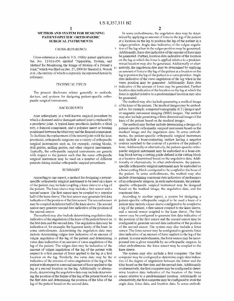
2O BACKGROUND
Joint arthroplasty is a well-known Surgical procedure by which a diseased and/or damaged natural joint is replaced by a prosthetic joint. A typical knee prosthesis includes a tibial 25 tray, a femoral component, and a polymer insert or bearing positioned between the tibial tray and the femoral component. To facilitate the replacement of the natural joint with the knee prosthesis, orthopaedic Surgeons use a variety of orthopaedic Surgical instruments such as, for example, cutting blocks, 30 drill guides, milling guides, and other Surgical instruments. Typically, the orthopaedic surgical instruments are generic with respect to the patient Such that the same orthopaedic Surgical instrument may be used on a number of different patients during similar orthopaedic Surgical procedures. 35
SUMMARY
According to one aspect, a method for designing a patient specific orthopaedic Surgical instrument to be used on a knee 40 of the patient may include coupling a knee sleeve to a leg of the patient. The knee sleeve may include a first sensor and a second sensor. The first sensor may be coupled to a Superior half of the knee sleeve. The first sensor may generate first data indicative of the position of the first sensor. The second sensor 45 may be coupled an inferior half of the knee sleeve. The second sensor may generate second data indicative of the position of the second sensor.
The method may also include determining angulation data indicative of the angulation of the knee of the patient based on 50 the first data and the second data. The angulation data may be indicative of, for example, the ligament laxity of the knee. In Some embodiments, determining the angulation data may include determining Valgus data indicative of an amount of valgus angulation of the leg of the patient and determining 55 Varus data indicative of an amount of Varus angulation of the leg of the patient. The Valgus data may be indicative of the amount of Valgus angulation of the leg of the patient with respect to a first amount of force applied to the leg at a first location on the leg. Similarly, the Varus data may be the 60 indicative of the amount of Varus angulation of the leg of the patient with respect to a second amount of force applied to the leg at a second location on the leg. Additionally or alterna tively, determining the angulation data may include determin ing the position of the femur of the leg of the patient based on 65 the first data and determining the position of the tibia of the leg of the patient based on the second data.
2 In some embodiments, the angulation data may be deter
mined by applying an amount of force to the leg of the patient at a location on the leg to position the leg of the patient in a valgus position. Angle data indicative of the Valgus angula tion of the leg when in the valgus position may be generated. Additionally, force data indicative of the amount of force may be generated. Further, location data indicative of the location on the leg at which the force is applied relative to a predeter mined location may also be generated. Additionally or alter natively, the angulation data may be determined by applying an amount of force to the leg of the patient at a location on the leg to position the leg of the patient in a Varus position. Angle data indicative of the Varus angulation of the leg when in the Varus position may be generated. Additionally, force data indicative of the amount of force may be generated. Further location data indicative of the location on the leg at which the force is applied relative to a predetermined location may also be generated. The method may also include generating a medical image
of the knee of the patient. The medical images may be embod ied as, for example, computed tomography (CT) images and/ or magnetic resonance imaging (MRI) images. The method may also include generating a three dimensional image of the knee of the patient based on the medical images. The method may further include determining a design of a
patient-specific orthopaedic Surgical instrument based on the medical image and the angulation data. In some embodi ments, the patient-specific orthopaedic Surgical instrument may include a bone-contacting Surface having a negative contour matched to the contour of a portion of the patients bone. Additionally or alternatively, the patient-specific ortho paedic surgical instrument may be embodied as a bone-cut ting block having a cutting guide defined in the cutting block at a location determined based on the angulation data. Addi tionally or alternatively, in other embodiments, the patient specific orthopaedic Surgical instrument may be embodied as a bone-cutting block configured to be coupled to the bone of the patient. In some embodiments, the method may also include determining constraint data indicative of preferences of an orthopaedic Surgeon. In Such embodiments, the patient specific orthopaedic Surgical instrument may be designed based on the medical image, the angulation data, and the constraint data.
According to another aspect, a system for designing a patient-specific orthopaedic Surgical to be used a knee of a patient may include a knee sleeve configured to be coupled to a leg of the patient, a first sensor coupled to the knee sleeve, and a second sensor coupled to the knee sleeve. The first sensor may be configured to generate first data indicative of the position of the first sensor and the second sensor may be configured to generate second data indicative of the position of the second sensor. The system may also include a force sensor. The force sensor may be configured to generate force data indicative of an amount of force applied to the leg of the patient. In some embodiments, the force sensor may be incor porated into a glove wearable by an orthopaedic Surgeon. In other embodiments, the force sensor may be coupled to the knee sleeve. The system may also include a first computer. The first
computer may be configured to determine angle data indica tive of the degree of angulation between the femur and the tibia based on the first data and the second data. Additionally or alternatively, the first computer may be configured to deter mine location data indicative of the location of the force sensor relative to a predetermined location. Additionally or alternatively, the first computer may be configured to store the angle data, force data, and location data. In some embodi

US 8,357,111 B2 3
ments, the first computer may also be configured to determine third data indicative of the position of the femur of the leg of the patient based on the first data and to determine fourth data indicative of the position of the tibia of the leg of the patient. The system may also include a second computer in some
embodiments. The second computer may be remote from the first computer. The second computer may be configured to generate a three-dimensional model of the customized patient orthopaedic Surgical instrument based on the angle data, force data, and location data
According to a further aspect, a method for designing a patient-specific orthopaedic Surgical may include coupling a knee sleeve to a leg of the patient. The knee sleeve may include a first sensor coupled to a superior half of the knee sleeve and a second sensor coupled to an inferior half of the knee sleeve. The first sensor may generate first data indicative of the position of the first sensor and the second sensor may generate second data indicative of the position of the second SSO.
The method may also include generating laxity data indica tive of the ligament laxity of the knee of the patient based on the first and second data. The method may also include gen erating a design of a patient-specific orthopaedic Surgical instrument based on the laxity data. In some embodiments, the method may also include generating a medical image of the knee of the patient. In Such embodiments, the patient specific orthopaedic Surgical instrument is designed based on the laxity data and the medical image.
In some embodiments, the laxity data may be generated by, for example, applying a first amount of force to the leg at a first location on the leg to position the leg of the patient in a valgus position, generating first angle data indicative of the valgus angulation of the leg when in the Valgus position, generating first force data indicative of the first amount of force, and generating first location data indicative of the first location relative to a predetermined location. Additionally or alternatively, the laxity data may be generated by applying a second amount of force to the leg at a second location on the leg to position the leg of the patient in a Varus position, generating second angle data indicative of the Varus angula tion of the leg when in the Varus position, generating second force data indicative of the second amount of force, generat ing second location data indicative of the second location relative to the predetermined location. In such embodiments, the orthopaedic Surgical instrument may be designed based on the first angle data, the first force data, the first location data, the second angle data, the second force data, and the second location data.
BRIEF DESCRIPTION OF THE DRAWINGS
The detailed description particularly refers to the following figures, in which:
FIG. 1 is a lateral elevation view of one embodiment of an apparatus for determining the angulation of a patient’s knee;
FIG. 2 is an anterior elevation view of the apparatus of FIG. 1;
FIG. 3 is a cross-sectional view of one embodiment of a knee sleeve of the apparatus of FIG. 1;
FIG. 4 is a cross-sectional view of another embodiment of the knee sleeve of the apparatus of FIG. 1;
FIG. 5 is a simplified block diagram of one embodiment of the sensing circuitry of the apparatus of FIG. 1;
FIG. 6 is a simplified block diagram of one embodiment of a sensor circuit of the sensing circuitry of FIG. 3;
10
15
25
30
35
40
45
50
55
60
65
4 FIG. 7 is a simplified flow diagram of an algorithm for
transmitting sensor data, which may be executed by the com munication circuit of the system of FIG. 5:
FIG. 8 is a simplified block diagram of a system for design ing a patient-specific orthopaedic Surgical instrument;
FIG. 9 is a simplified block diagram of an algorithm for designing a patient-specific orthopaedic Surgical instrument;
FIG. 10 is a simplified block diagram of an algorithm for determining a angulation of the patient's joint;
FIG.11 is an anterior elevation view of a joint of the patient shown in one position of manipulation;
FIG. 12 is an anterior elevation view of the joint of the patient of FIG. 11 shown in another position of manipulation; and
FIG. 13 is a perspective view of one embodiment of a patient customized orthopaedic Surgical tool fabricated according to the algorithm of FIG. 9.
DETAILED DESCRIPTION OF THE DRAWINGS
While the concepts of the present disclosure are suscep tible to various modifications and alternative forms, specific exemplary embodiments thereofhave been shown by way of example in the drawings and will herein be described in detail. It should be understood, however, that there is no intent to limit the concepts of the present disclosure to the particular forms disclosed, but on the contrary, the intention is to cover all modifications, equivalents, and alternatives falling within the spirit and scope of the invention as defined by the appended claims.
Referring to FIG. 1, an apparatus 10 for determining the range of motion and/or angulation of a patient’s knee 12 includes a knee sleeve 14 and sensing circuitry 16 coupled to the knee sleeve 14. The knee sleeve 14 includes a superior half 22 and an inferior half 24 defined by a bisecting plane 20. The knee sleeve 14 has a Substantially cylindrical shape having an opening at each end and an inner cavity defined therebetween through which the leg of the patient is inserted when the knee sleeve 14 is worn by the patient. As illustrated in FIG.1, when the knee sleeve 14 is wornby
the patient, the superior half 22 of the knee sleeve covers a portion of the distal end of the patient’s femur 26 and the inferior half 24 covers a portion of the proximal end of the patient’s tibia 28. The knee sleeve 14 may beformed from any flexible material that allows the patient to move the knee joint 12 between a flexion position and an extension position. For example, the knee sleeve 14 may be formed from a stretch able, form-fitting textile such as a neoprene material, nylon, a spandex material such as LycraTM, or the like. Additionally, in some embodiments, the knee sleeve 14 may be formed from a sterilized material such that the knee sleeve 14 may be worn by the patient soon after the Surgical procedure and/or during post-Surgery recovery. The knee sleeve 14 may be sized based on one or more
parameters such as the physical size of the patient. For example, the knee sleeve 14 is sized such that the knee sleeve 14 covers only the knee joint region of the patient's leg. That is, when the knee sleeve 14 is worn by the patient, the superior half 22 of the knee sleeve 14 does not extend up to the groin region of the patient and the inferior half 24 does not extend down to the ankle region of the patient. Because the knee sleeve 14 is worn only around the knee joint region of the patient’s leg, the natural movement of the patient’s joint is not substantially affected by the use of the knee sleeve 14 unlike a full-leg sleeve or full body suit, which extends from groin to-ankle. Although the knee sleeve 14 does not substantially affect the natural movement of the patient’s joint, the knee

US 8,357,111 B2 5
sleeve 14 may provide some amount of additional Support to the knee joint in Some embodiments.
In the illustrative embodiment, the sensing circuitry 16 includes a number of sensor circuits 30, 32, 34, 36 and a communication circuit 38. In some embodiments, the sensor circuits 30, 32, 34, 36 and the communication circuit 38 are incorporated into the knee sleeve 14. For example, the circuits 30, 32,34, 36,38 may be woven into the material forming the knee sleeve 14 or otherwise attached to the knee sleeve 14 in a non-removable manner using, for example, a permanent adhesive or the like.
Alternatively, in other embodiments, the sensor circuits 30, 32, 34, 36 and the communication circuit 38 may be remov ably attached to the knee sleeve 14. For example, as illustrated in FIG. 3, the sensor circuits 30, 32, 34, 36 and/or the com munication circuit 38 may be removably attached to the knee sleeve 14 using an attaching member 40, such as a hook-and loop material or other non-permanent adhesive. In Such embodiments, the attaching member 40, or a portion thereof, may be secured to a housing (see FIG. 6) of the circuit 30, 32. 34, 36,38. In use, the sensor circuits 30, 32,34, 36 and/or the communication circuit 38 may be attached to the knee sleeve 14 by pressing the attaching member 40 onto the knee sleeve 14. In such embodiments, the sensor circuits 30, 32, 34, 36 and the communication circuit 38 may be coupled to the knee sleeve 14 during use and decoupled thereform when not in use. Additionally, in embodiments wherein the circuits 30, 32, 34, 36, 38 are removable from the knee sleeve 14, the circuits 30, 32, 34, 36, 38 may be reusable while the knee sleeve 14 is disposed of after each use or otherwise periodi cally.
In some embodiments, as illustrated in FIG. 4, the knee sleeve may include a number of apertures 42. The apertures 42 are sized to receive at least a portion of one of the sensor circuits 30, 32, 34, 36. That is, when the sensor circuit 30, 32, 34, 36 is coupled to the knee sleeve 14, a portion of the sensor circuit 30, 32, 34, 36 is positioned in the aperture 42. The sensor circuit 30, 32, 34, 36 is held in place via an attaching member 44, which wraps over the sensor circuit 30, 32,34, 36 and contacts a portion of the knee sleeve 14 at distal ends 46. 48. The attaching member 44 may be similar to the attaching member 40 described above in regard to FIG. 3. For example, the attaching member 44 may be secured to a top surface 50 of the sensor circuit 30, 32, 34, 36 and formed from a hook and-loop material. When the sensor circuit 30, 32, 34, 36 is positioned in the
aperture 42, a bottom surface 52 of the sensor circuit 30, 32. 34, 36 may be positioned in contact with the skin of the patient. The knee sleeve 14 may include any number of aper tures 42. In one particular embodiment, the knee sleeve 14 includes one aperture 42 for each sensor circuit 30, 32,34, 36. Additionally, the apertures 42 may be defined in knee sleeve 14 in predetermined locations such that the sensor circuits 30, 32, 34, 36 are similarly located when coupled thereto. For example, as discussed in more detail below, one or more apertures 42 may be defined on a lateral side of the knee sleeve 14 and one or more additional apertures 42 may be defined on the anterior side of the knee sleeve 14.
Referring back to FIGS. 1 and 2, the sensor circuits 30, 32, 34, 36 are positioned on the knee sleeve 14 such that one or more of the sensor circuits 30, 32, 34, 36 is located on each side (i.e., the Superior and inferior sides) of the knee joint 12 of the patient. In particular, sensor circuit 30 is coupled on the lateral side of the superior half 22 of the knee sleeve 12 and the sensor circuit 32 is coupled on the lateral side of the inferior half 24 of the knee sleeve as illustrated in FIG. 1. Additionally, as illustrated in FIG. 2, the sensor circuit 34 is
5
10
15
25
30
35
40
45
50
55
60
65
6 coupled on the anterior side of the superior half 22 of the knee sleeve 12 and the sensor circuit 36 is coupled on the anterior side of the inferior half 24 of the knee sleeve 12. Although the illustrative apparatus 10 includes four sensor circuits, it should be appreciated that in other embodiments a greater or lesser number of sensor circuits may be used. For example, in Some embodiments, only two sensor circuits are used and each sensor circuit is positioned on one side of the knee joint 12 (e.g., similar to sensor circuits 30, 32). However, by using additional sensor circuits, such as sensor circuits 34, 36, an amount of redundancy and an improvement in measurement accuracy may be achieved with the apparatus 10.
In the illustrative embodiment, the sensor circuits 30, 34 and the sensor circuits 32.36 are positioned on the lateral and anterior side of the knee sleeve 14 to reduce the likelihood that any one of the sensor circuits 30, 32, 34, 36 obstructs the normal movement of the patient or becomes dislodged from the knee sleeve 14. For example, Such positioning of the sensor circuits 30, 32, 34, 36 may reduce the likelihood that the sensor circuits 30, 32, 34, 36 inadvertently become dis lodged from the knee sleeve 14 by movement of the patient from, for example, being repeatedly hit or rubbed by the leg of the patient as may be the case if sensor circuits were located on the medial side of the knee sleeve 14. However, in other embodiments, the sensor circuits 30, 34 and 32, 36 may be positioned in other locations on the knee sleeve 14.
Each of the sensor circuits 30, 32, 34, 36 is electrically coupled to the communication circuit 38 via a number of communication links 60, 62, 64, 66, respectively. The com munication links 60, 62, 64, 66 may be embodied as any type of communication link capable of providing electrical com munication between the sensor circuits 30, 32, 34, 36 and the communication circuit 38. For example, the communication links 60, 62. 64, 66 may be embodied as any number of wires, cables, fiber optic cables, and/or the like. In some embodi ments, the sensor circuits 30, 32, 34, 36 may be removably coupled to the communication circuit 38. For example, as illustrated in FIG. 5, the sensor circuits 30, 32,34, 36 may be communicatively coupled to the communication circuit 38 via connectors 70, 72, 74, 76. In this way, individual sensor circuits that become damaged over time may be replaced without the requirement of replacing the communication cir cuit 38. In addition, only those sensor circuits required for the particular application or implementation may be coupled to the communication circuit 38. For example, in those embodi ments including only two sensor circuits rather than four, the sensor circuits 30, 32 may be coupled to the communication circuit 38 and to the knee sleeve 14, while the sensor circuits 34 and 36 are decoupled from the communication circuit 38 and removed. As illustrated in FIG. 5, the communication circuit 38
includes a transmitter 80. The transmitter 80 is configured to receive the sensor data signals from the sensor circuits 30, 32. 34, 36 and transmit the sensor data signals to a receiver Such as a remote computer as discussed below in more detail in regard to FIG. 7. The transmitter 80 may be embodied as any transmitter circuitry capable of wirelessly transmitting the data signals received from the sensor circuits 30, 32, 34, 36. The transmitter 80 is sized to allow the communication circuit 38 to be coupled to or incorporated in the knee sleeve 14 while not falling off due to gravity or use or otherwise causing the knee sleeve 14 to become improperly positioned during use. In some embodiments, the communication circuit 38 also includes a memory device 82. The memory device 82 may be embodied as any type of memory device Such as, for example, a random access memory (RAM) device. In Such embodi ments, the transmitter 80 or associated circuitry may be con
US 8,357,111 B2 7
figured to store the sensor data received from the sensor circuits 30, 32, 34, 36 in the memory device 82. In addition, the transmitter 80 or associated circuitry may be configured to retrieve stored sensor data from the memory device 82 and transmit the stored sensor data to a receiver Such as a remote computer.
Although the communication circuit 38 is illustrated in FIG. 5 as a single circuit, in some embodiments, the commu nication circuit 38 may be embodied as any number of trans mitters similar to transmitter 80, which may or may not be communicatively coupled to each. In Such embodiments, each transmitter may be electrically coupled to a respective one of the sensor circuits 30, 32, 34, 36 and may further form a portion of the respective sensor circuit 30, 32,34, 36 in some embodiments. For example, in one particular embodiment, the communication circuit 38 is formed from a first transmit ter electrically coupled to the sensor circuit 30, a second transmitter electrically coupled to the sensor circuit 32, a third transmitter electrically coupled to the sensor circuit 34, and a fourth transmitter electrically coupled to the sensor circuit 36. Additionally, in Such embodiments, any one or more of the sensor circuits 30, 32, 34, 36 may include a memory device similar to memory device 82.
Referring now to FIG. 6, each of the sensor circuits 30, 32, 34, 36 includes a housing 90 and a position sensor 92. The housing 90 may be formed from any material capable of Supporting the position sensor 92 and associated circuitry and being coupled to the knee sleeve 14. In one particular embodi ment, the housing 90 is formed from a plastic material, but other materials may be used in other embodiments. In embodiments wherein the knee sleeve 14 includes apertures 42, the housing 90 or a portion thereof is sized to be posi tioned in one of the apertures 42. The position sensor 92 may be embodied as any sensor capable of generating sensor data indicative of the position of the sensor 92. As used herein, the term “position' is intended to mean the spatial location of an object (e.g., the sensor 92) relative to a reference point and/or the spatial orientation of an object (e.g., the sensor 92) relative to a reference axis. For example, in one particular embodi ment, the position sensor 92 may be embodied as a micro electromechanical system (MEMS) sensor, Such as an accel erometer, configured to generate sensor data indicative of the orientation of the position sensor 92 with respect to the Earth's gravitational field. However, in other embodiments, the position sensor 92 may be embodied as any other type of position sensor, such as optical and/or magnetic position sen sors, configured to generate data indicative of the location and/or the orientation of the sensor from which the position of an associated bone of the patient may be determined as described in more detail below in regard to FIG. 10.
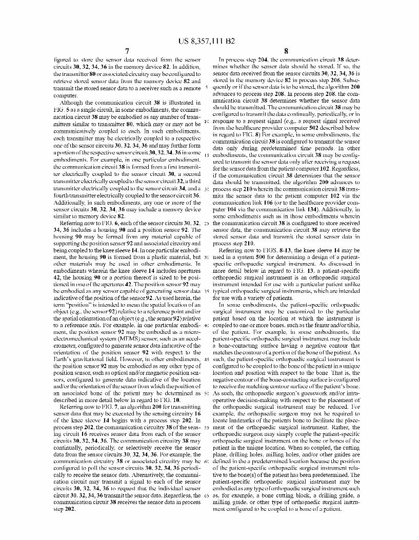
Referring now to FIG. 7, an algorithm 200 for transmitting sensor data that may be executed by the sensing circuitry 16 of the knee sleeve 14 begins with a process step 202. In process step 202, the communication circuitry 38 of the sens ing circuit 16 receives sensor data from each of the sensor circuits 30, 32, 34, 36. The communication circuitry 38 may continually, periodically, or selectively receive the sensor data from the sensor circuits 30, 32, 34, 36. For example, the communication circuitry 38 or associated circuitry may be configured to poll the sensor circuits 30, 32, 34, 36 periodi cally to receive the sensor data. Alternatively, the communi cation circuit may transmit a signal to each of the sensor circuits 30, 32, 34, 36 to request that the individual sensor circuit 30, 32,34, 36 transmit the sensor data. Regardless, the communication circuit 38 receives the sensor data in process step 202.
10
15
25
30
35
40
45
50
55
60
65
8 In process step 204, the communication circuit 38 deter
mines whether the sensor data should be stored. If so, the sensor data received from the sensor circuits 30, 32, 34, 36 is stored in the memory device 82 in process step 206. Subse quently or if the sensor data is to be stored, the algorithm 200 advances to process step 208. In process step 208, the com munication circuit 38 determines whether the sensor data should be transmitted. The communication circuit 38 may be configured to transmit the data continually, periodically, or in response to a request signal (e.g., a request signal received from the healthcare provider computer 502 described below in regard to FIG. 8) For example, in some embodiments, the communication circuit 38 is configured to transmit the sensor data only during predetermined time periods. In other embodiments, the communication circuit 38 may be config ured to transmit the sensor data only after receiving a request for the sensor data from the patient computer 102. Regardless, if the communication circuit 38 determines that the sensor data should be transmitted, the algorithm 200 advances to process step 210 wherein the communication circuit 38 trans mits the sensor data to the patient computer 102 via the communication link 106 (or to the healthcare provider com puter 104 via the communication link 134). Additionally, in Some embodiments such as in those embodiments wherein the communication circuit 38 is configured to store received sensor data, the communication circuit 38 may retrieve the stored sensor data and transmit the stored sensor data in process step 210.
Referring now to FIGS. 8-13, the knee sleeve 14 may be used in a system 500 for determining a design of a patient specific orthopaedic Surgical instrument. As discussed in more detail below in regard to FIG. 13, a patient-specific orthopaedic Surgical instrument is an orthopaedic Surgical instrument intended for use with a particular patient unlike typical orthopaedic Surgical instruments, which are intended for use with a variety of patients.
In some embodiments, the patient-specific orthopaedic Surgical instrument may be customized to the particular patient based on the location at which the instrument is coupled to one or more bones. Such as the femur and/or tibia, of the patient. For example, in Some embodiments, the patient-specific orthopaedic Surgical instrument may include a bone-contacting Surface having a negative contour that matches the contour of a portion of the bone of the patient. As Such, the patient-specific orthopaedic Surgical instrument is configured to be coupled to the bone of the patient in a unique location and position with respect to the bone. That is, the negative contour of the bone-contacting Surface is configured to receive the matching contour Surface of the patient's bone. As such, the orthopaedic Surgeon’s guesswork and/or intra operative decision-making with respect to the placement of the orthopaedic Surgical instrument may be reduced. For example, the orthopaedic Surgeon may not be required to locate landmarks of the patients bone to facilitate the place ment of the orthopaedic Surgical instrument. Rather, the orthopaedic Surgeon may simply couple the patient-specific orthopaedic Surgical instrument on the bone or bones of the patient in the unique location. When so coupled, the cutting plane, drilling holes, milling holes, and/or other guides are defined in the a predetermined location because the position of the patient-specific orthopaedic Surgical instrument rela tive to the bone(s) of the patient has been predetermined. The patient-specific orthopaedic Surgical instrument may be embodied as any type of orthopaedic Surgical instrument Such as, for example, a bone cutting block, a drilling guide, a milling guide, or other type of orthopaedic Surgical instru ment configured to be coupled to a bone of a patient.

US 8,357,111 B2
Referring to FIG. 8, the system 500 includes a healthcare provider computer 502 located in a healthcare facility 504 such as a hospital facility or the office of the orthopaedic surgeon. The system 500 also includes a manufacturer com puter 506 located in the facility of a manufacturer or vendor of patient-specific orthopedic Surgical instruments. The health care provider computer 502 is communicatively coupled to the manufacture computer 506 via a network 510. The net work 510 may be embodied as any type of communication network capable of facilitating communication between the healthcare provider computer 502 and the manufacturer.com puter 506. For example, the network510 may be embodied as a wide area network (WAN), a local area network (LAN), or form a portion of a publicly-accessible, global network Such as, for example, the Internet. In addition, the network 510 may be a wired network, a wireless network, or a combination thereof. As such, the network510 may include any number of devices for providing communication between the computers 502,506 such as routers, switches, hubs, computers, commu nication links, and the like. The healthcare provider computer 502 is coupled to the
network510 via a number of communication links 512. Simi larly, the manufacturer computer 506 is coupled to the net work 510 via a number of communication links 514. The communication links 512, 514 may be embodied as any type of communication links capable of providing communication between the healthcare provider computer 502 and the manu facturer computer 506. For example, the communication links 512, 514 may be embodied as any number of cables, wires, fiber optic cables, wireless signals, and/or the like.
The healthcare provider computer 502 is also communica tively coupled to the knee sleeve 14 (e.g., the communication circuitry 38 of the knee sleeve 14) via a number of commu nication links 516. The communication links 516 may be embodied as any type of communication links capable of facilitating communication between the sensing circuit 16 of the knee sleeve 14 and the healthcare provider computer 502. For example, the communication links 516 may be embodied as any number of cables, wires, fiber optic cables, wireless signals, and/or the like. The healthcare provider computer 502 is also communicatively coupled to a force sensor circuit 520 via a number of communication links 522. Similar to the communication links 516, the communication links 522 may be embodied as any type of communication links capable of facilitating communication between the force sensor circuit 520 and the healthcare provider computer 502. For example, the communication links 522 may be embodied as any num ber of cables, wires, fiber optic cables, wireless signals, and/ or the like. The force sensor circuit 520 includes a force sensor 524, a
position sensor 526, and a communication circuitry 528. The force sensor 524 may be embodied as any sensor capable of generating sensor data indicative of an amount of force applied to the sensor. For example, in one particular embodi ment, the force sensor 524 is embodied as a pressure sensor Such as a strain gauge. However, in other embodiments, the force sensor 524 may be embodied as any other type of force sensor configured to generate data indicative of the amount of force applied to the force sensor 524. The position sensor 526 may be embodied as any sensor
capable of generating sensor data indicative of the position of the sensor 526. For example, in one particular embodiment, the position sensor 526 may be embodied as a microelectro mechanical system (MEMS) sensor, such as an accelerom eter, configured to generate sensor data indicative of the ori entation of the position sensor 526 with respect to the Earth's gravitational field. However, in other embodiments, the posi
5
10
15
25
30
35
40
45
50
55
60
65
10 tion sensor 526 may be embodied as any other type of position sensor, such as optical and/or magnetic position sensors, con figured to generate data indicative of the location and/or the orientation of the sensor. The communication circuitry 528 may be substantially
similar to the communication circuitry 38 of the knee sleeve 14. For example, similar to the communication circuitry 38 illustrated in FIG. 5, the communication circuitry 528 may include a transmitter (not shown). The transmitter is config ured to receive the sensor data signals from the force sensor 524 and transmit the sensor data signals to a receiver Such as the healthcare provider computer 524 via the communication link 522. The transmitter may be embodied as any transmitter circuitry capable of transmitting the data signals received from the force sensor 524.
In some embodiments, the force sensor circuit 520 is embodied as a stand-alone device separate from the knee sleeve 516. For example, as discussed below in more detail in regard to FIGS. 10-12, the force sensor circuit 520 may be incorporated into a glove wearable by the orthopaedic Sur geon. Alternatively, the force sensor circuit 520 may be embodied as a device sized to be held by the orthopaedic surgeon. In other embodiments, the force sensor circuit 520 is coupled to the knee sleeve 14. In such embodiments, the force sensor circuit 520 may be coupled toward a distal end of the inferior half of the knee sleeve 14. As discussed in more detail below, the force sensor circuit 520 is configured to generate force data indicative of the amount of force applied to the leg of the patient by the Surgeon during manipulation of the patient’s leg. The healthcare provider computer 502 includes a processor
530, memory device 532, and, in some embodiments, a dis play 534. The processor 530 may be embodied as any type of processor including, for example, discrete processing cir cuitry (e.g., a collection of logic devices), general purpose integrated circuit(s), and/or application specific integrated circuit(s) (i.e., ASICs). The memory device 532 may be embodied as any type of memory device and may include one or more memory types, such as, random access memory (i.e., RAM) and/or read-only memory (i.e., ROM). The display 534 may be embodied as any type of display or display device capable of displaying data and images to a user (e.g., an orthopaedic) of the healthcare provider computer 502. In some embodiments, the display 534 forms an integral portion of the healthcare provider computer 502. However, in other embodiments, the display 534 may be separate from the healthcare provider computer 502, but communicatively coupled therewith. The healthcare provider computer 502 also includes com
munication circuitry 536 to facilitate communication with the knee sleeve 14 (via the communication circuitry 38), the manufacturer computer 506 via the network 510, and the force sensor circuit 520. As such, the communication cir cuitry 536 may include transmitter and/or receiver circuitry. Additionally, the communication circuitry 536 may be con figured to communicate with the knee sleeve 14, the manu facturer computer 506, the force sensor circuit 530, and/or other devices using wired or wireless communication proto cols depending upon, for example, the type of communica tion link 516, 522 and/or the type of network 510. For example, in embodiments wherein the network510 is a wire less network, the communication circuitry 536, or portion thereof, may be embodied as a wireless communication cir cuitry.
Additionally, in Some embodiments, the healthcare pro vider computer 502 may also include a portable media inter face 538. The portable media interface 538 is configured to

US 8,357,111 B2 11
receive a portable media device 540. In the illustrative embodiment, the portable media interface 538 is embodied as a Universal Serial Bus (USB) port. However, in other embodi ments, the portable media interface 538 may be embodied as any type of serial port, parallel port, flash drive port, or other data port capable of communicating with and storing data on the portable media device 540. The portable media device 540 may be embodied as any portable memory device configured for the purpose of transporting data from one computer sys tem to another computer system. In some embodiments, the portable media memory device 540 is embodied as a remov able solid-state memory device such as a removable flash memory device. For example, the portable media device 540 may be embodied as a Memory.StickTM flash memory device, a SmartMediaTM flash memory device, or a CompactFlashTM flash memory device. Alternatively, in other embodiments, the portable media device 540 may be embodied as a memory device having a microdrive for data storage. Regardless, the portable media memory device 540 is capable of storing data Such as sensor data for later retrieval.
In addition, the healthcare provider computer 502 may include other devices and circuitry typically found in a com puter for performing the functions described herein such as, for example, a hard drive, input/output circuitry, and the like. As such, the healthcare provider computer 502 may be embodied as any type of computer or computing device capable of receiving data from knee sleeve 14 and the force sensor circuit 520. For example, the healthcare provider com puter 502 may be embodied as a typical desktop or laptop computer equipped with a display Screen, keyboard, and other devices and circuitry typically found in a desktop and/or laptop computer. Alternatively, the healthcare provider com puter 502 may be embodied as an application specific com puter or computer device configured to perform the functions described herein. Further, in some embodiments, the health care provider computer 502 may form a portion of a hospital network or otherwise be communicatively coupled to such a network. The system 500 also includes an imaging system 542
located at the healthcare facility 504. The imaging system 542 may be embodied as any type of imaging system 542 capable of generating medical images of the patient’s bony anatomy. For example, the imaging system may be embodied as a computed tomography (CT) imaging device, a magnetic reso nance imagining (MRI) device, or other imaging system. In Some embodiments, the imagining system 542 is communi catively coupled to the vendor computer 506 via the network 510 and a number of communication links 544. In such embodiments, the communication links 544 may be embod ied as any type of communication links capable of providing communication between the imaging system 542 and the manufacturer computer 506. For example, the communica tion links 544 may be embodied as any number of cables, wires, fiber optic cables, wireless signals, and/or the like. In Some embodiments, the imagining system 542 may be com municatively coupled to a network of the healthcare facility, which in turn may be communicatively coupled to the net work 510. Additionally, in some embodiments, the imaging system 542 may include a database (not shown) or otherwise be communicatively coupled to the database and configured to store the medical images in the database. In such embodi ments, database may include a Patient Archiving Communi cations System (PACS) that stores medical images for patients of the healthcare facility 504. The manufacturer computer 506 includes a processor 550,
memory device 552, and, in some embodiments, a display 554. The processor 550 may be embodied as any type of
10
15
25
30
35
40
45
50
55
60
65
12 processor including, for example, discrete processing cir cuitry (e.g., a collection of logic devices), general purpose integrated circuit(s), and/or application specific integrated circuit(s) (i.e., ASICs). The memory device 552 may be embodied as any type of memory device and may include one or more memory types, such as, random access memory (i.e., RAM) and/or read-only memory (i.e., ROM). The display 554 may be embodied as any type of display or display device capable of displaying data and images to a user (e.g., an orthopaedic) of the manufacturer computer 506. In some embodiments, the display 554 forms an integral portion of the manufacturer computer 506. However, in other embodi ments, the display 554 may be separate from the manufac turer computer 506, but communicatively coupled therewith. The manufacturer computer 506 also includes communi
cation circuitry 556 to facilitate communication with health care provider computer 502 via the network510. As such, the communication circuitry 556 may include transmitter and/or receiver circuitry. Additionally, the communication circuitry 556 may be configured to communicate with the healthcare provider computer 502 using wired or wireless communica tion protocols depending upon, for example, the type of net work510. For example, in embodiments wherein the network 510 is a wireless network, the communication circuitry 556, orportion thereof, may be embodied as a wireless communi cation circuitry.
Additionally, in Some embodiments, the manufacturer computer 506 may also include a portable media interface 558. The portable media interface558 is configured to receive the portable media device 540. In the illustrative embodi ment, the portable media interface 558 is embodied as a Universal Serial Bus (USB) port. However, in other embodi ments, the portable media interface 558 may be embodied as any type of serial port, parallel port, flash drive port, or other data port capable of communicating with and storing data on the portable media device 540. As discussed above, the por table media device 540 may be embodied as any portable memory device configured for the purpose of transporting data from one computer system to another computer system.
In addition, the manufacturer computer 506 may include other devices and circuitry typically found in a computer for performing the functions described herein such as, for example, a hard drive, input/output circuitry, and the like. As such, the manufacturer computer 506 may be embodied as any type of computer or computing device capable of receiv ing data from healthcare provider computer 502 via the net work510 and/or the portable media device 540. For example, the manufacturer computer 506 may be embodied as a typical desktop or laptop computer equipped with a display screen, keyboard, and other devices and circuitry typically found in a desktop and/or laptop computer. Alternatively, the manufac turer computer 506 may be embodied as an application spe cific computer or computer device configured to perform the functions described herein.
In use, the orthopaedic Surgeon may operate the healthcare provider computer 502, the knee sleeve 14, and the force sensor circuit 520 to perform pre-operative planning on the patient’s joint. That is, via use of the knee sleeve 14 and the force sensor circuit 520, the orthopedic surgeon is able to investigate the Soft tissue structure of the patient’s joint pre operatively. For example, the orthopaedic Surgeon may utilize the knee sleeve 14, the force sensor circuit 520, and the computer 502 to determine the angulation of the patients joint (e.g., the angle defined between the patients femur and tibia). The joint angulation investigation may include deter mining the ligament laxity of the relevant joint. Such infor mation, along with medical images of the patient's joint gen

US 8,357,111 B2 13
erated via the imaging system 542, may Subsequently be provided to the manufacturer computer 506 to facilitate the design of a patient-specific orthopaedic Surgical instrument. The joint angulation data, the medical images, and any addi tional constraint data or Surgeon preferences may be trans mitted to the manufacturer computer 508 via the network510 or the portable media device 540. The manufacturer computer 508 uses the medical images, angulation data, and any addi tional Surgeon constraint data to generate a design or model of the patient-specific orthopaedic Surgical instrument. The design may be embodied as a set of instructions. Such as fabrication instructions, a model, or other data that defines the embodiment of the patient-specific orthopaedic Surgical instrument may be fabricated. For example, in embodiments wherein the design is embodied as a model of the instrument, the model may be a three-dimensional software model or a prototype model, which is sent to or otherwise viewable by the Surgeon to determine the accuracy of the model or other wise validate the design.
Referring now to FIG. 9, a method 600 for designing a patient-specific orthopaedic Surgical instrument includes a number of process steps 602, 604, 606 in which the ortho paedic Surgeon performs an amount of pre-operative plan ning. The process steps 602, 604, 606 may be completed in any order or contemporaneously with each other. In process step 602, a number of medical images of the relevant bony anatomy or joint of the patient are generated. To do so, the orthopaedic Surgeonor other healthcare provider may operate the imaging system 542 to generate the medical images. The medical images may be embodied as any number and type of medical images capable of being used to generate a three dimensional model of the patient’s joint. For example, the medical images may be computed tomography (CT) images, magnetic resonance imaging (MRI) images, or other type of medical images. The medical images may be stored in a suitable database, in the healthcare provider computer 502, or other Suitable storage facility.
In process step 604, the orthopaedic Surgeon determines the angulation of the patient’s joint. For example, the ortho paedic Surgeon may determine the ligament laxity of the relevant patient’s joint. Such information is Subsequently used in the designing of the patient-specific orthopaedic Sur gical instrument. To determine the angulation data, the ortho paedic Surgeon may utilize an algorithm 650 for determining angulation data related to the patient’s joint as illustrated in FIG 10. The algorithm 650 begins with a process step 652 in which
the knee sleeve 14 is coupled to the patient’s leg. After the knee sleeve 14 has been coupled to the patient, the ortho paedic Surgeon positions the patient’s leg in the normal ana tomical position in process step 654. In process step 656, the healthcare provider computer 502 is configured to calculate the position of the relevant bones or bony anatomy (e.g., the patient’s tibia and femur) of the patient based on the sensor data received from the knee sleeve 14. For example, the healthcare provider computer 502 may be configured to deter mine the position of the relevant femur and the tibia of the patient relative to each other based on the sensor data gener ated by the position sensors 92 of the sensor circuits 30, 32. 34, 36. In embodiments wherein the position sensors 92 are embodied as accelerometers generating data indicative of the position of the position sensor 92 relative to the Earth’s gravi tational field, the healthcare provider computer 502 may determine the relative position of the patient’s femur and tibia by comparing the sensor data generated by those sensor cir cuits 30, 34 positioned on the superior half of the knee sleeve 14 and those sensor circuits 32.36 positioned on the inferior
10
15
25
30
35
40
45
50
55
60
65
14 half of the knee sleeve 14. By determining the location of the patient’s boney anatomy in the natural anatomical position, the healthcare provider computer 502 establishes a reference from which deviation, such as Valgus and/or Varus angulation, can be determined as discussed below.
After the patient’s leg is positioned in the normal anatomi cal position, the Surgeon may manipulate the patient’s leg to investigate the soft tissue structure of the relevant joint. That is, the orthopaedic Surgeon may position the patient's leg in a valgus position (see steps 658-666) and a varus position (see steps 668-676) to determine the ligament laxity of the patient's knee. The orthopaedic Surgeon may position the patient’s leg in the Valgus and Varus positions in any order (e.g., valgus position first or Varus position first).
For example, as illustrated in step 658, the orthopaedic Surgeon positions the patient’s leg in a Valgus position by applying an amount of force at a location on the patients lower leg. As illustrated in FIG. 11, when the orthopaedic surgeon applies the amount of force 700 to the patient’s leg, the leg is moved in the lateral direction such that the femur 28 of the patient defines an angle 702 between the valgus posi tion (illustrated in phantom) and the normal anatomical posi tion (illustrated in solid) of the femur 28. In process step 660, the healthcare provider computer 502 is configured to calcu late the position of the relevant bones or bony anatomy (e.g., the patient's tibia and femur) of the patient based on the sensor data received from the knee sleeve 14. For example, as discussed above, the healthcare provider computer 502 may be configured to determine the position of the relevant femur and the tibia of the patient relative to each other based on the sensor data generated by the position sensors 92 of the sensor circuits 30, 32, 34, 36.
After the positions of the femur and tibia have been deter mined in process step 650, the healthcare provider computer 502 is configured to determine the valgus angulation of the patient joint in process step 662. To do so, the healthcare provider computer 502 may be configured to calculate the angle 702, or other data indicative of the Valgus angulation, based on the position of the femur and tibia in the valgus position relative to position of the femur and tibia in the normal anatomical position. For example, the healthcare pro vider computer 502 may be configured to compare the posi tion data of the tibia and the femur in the normal anatomical position and the Valgus position.
In process step 664, the amount of force 700 applied to the patient’s leg by the orthopaedic Surgeon required to position the patient’s leg in the Valgus position is determined. To do so, the force sensor circuit 520 is used by the orthopaedic sur geon. The force sensor circuit 520 is position between the orthopaedic Surgeons hand and the patient’s leg such that the amount of force applied by the Surgeon may be determined. As discussed above, in Some embodiments, the force sensor circuit 520 may be incorporated into a glove 704 worn by the orthopaedic Surgeon. In such embodiments, the force sensor circuit 520 (i.e., the force sensor 524) is positioned on the glove such that the circuitry 520 is positioned between the orthopaedic Surgeon’s hand and the patient’s leg. In other embodiments, the force sensor circuit 520 may be coupled to the knee sleeve 14. In such embodiments, the orthopedic surgeon applies the amount of force 700 to the patient’s leg on the location of the force sensor circuit 520. As discussed above in regard to FIG. 8, the force sensor circuit 520 is configured to transmit the force data generated in response to the application of the force 700 by the orthopaedic surgeon to the healthcare provider computer 502.
In addition to the amount of force 700 applied by the surgeon, the location of the application of the force 700 is

US 8,357,111 B2 15
determined in process step 666. For example, as illustrated in FIG. 11, the distance 706 at which the force 700 is applied to the patient’s leg with respect to a predetermined reference point may be determined. To do so, in one embodiment, the healthcare provider computer 502 is configured to determine a center point of the knee sleeve 14 based on the sensor data received from the sensor circuits 30, 32, 34, 36. For example, the healthcare provider computer 502 may determine the central location point in the coordinate system defined by the sensor circuits 30, 32, 34, 36. The healthcare provider com puter 502 may also determine the position of the force sensor circuit 520 based on the sensor data received from the posi tion sensor 526 of the circuit 520. The healthcare provider computer 520 may calculate the distance 706 based on the position of the force sensor circuit 520 relative to the prede termined location (e.g., the central location point in the coor dinate system defined by the sensor circuits 30, 32, 34, 36). After the Valgus angulation has been determined in process step 662, the amount of force 700 applied to the patient’s leg has been determined in process step 664, and the location of the applied force 700 has been determined in process step 666, the healthcare provider computer 502 stores the angula tion data (i.e., the angle 702, the amount of force 700, and the distance 706) in process step 678. The healthcare provider computer 502 may store the angulation data in the memory 532, in a database, or other suitable location. As discussed above, the orthopaedic Surgeon also positions
the patient’s leg in a Varus position by applying an amount of force at a location on the patient's lower leg in process step 668. As illustrated in FIG. 12, when the orthopaedic surgeon applies the amount of force 720 to the patient’s leg, the leg is moved in the medial direction such that the femur 28 of the patient defines an angle 722 between the Varus position (illus trated in phantom) and the normal anatomical position (illus trated in solid) of the femur 28. In process step 670, the healthcare provider computer 502 is configured to calculate the position of the relevant bones or bony anatomy (e.g., the patient’s tibia and femur) of the patient based on the sensor data received from the knee sleeve 14. As discussed above, the healthcare provider computer 502 may be configured to deter mine the position of the relevant femur and the tibia of the patient relative to each other based on the sensor data gener ated by the position sensors 92 of the sensor circuits 30, 32. 34, 36.
After the positions of the femur and tibia have been deter mined in process step 670, the healthcare provider computer 502 is configured to determine the Varus angulation of the patient joint in process step 672. To do so, the healthcare provider computer 502 may be configured to calculate the angle 722, or other data indicative of the Varus angulation, based on the position of the femur and tibia in the Varus position relative to position of the femur and tibia in the normal anatomical position. For example, the healthcare pro vider computer 502 may be configured to compare the posi tion data of the tibia and the femur in the normal anatomical position and the Varus position.
In process step 674, the amount of force 720 applied to the patient’s leg by the orthopaedic Surgeon required to position the patient’s leg in the Varus position is determined. As dis cussed above, the force sensor circuit 520 is position between the orthopaedic Surgeons hand and the patient’s leg such that the amount of force applied by the Surgeon may be deter mined. As discussed above in regard to FIG. 11, the force sensor circuit 520 is configured to transmit the force data generated in response to the application of the force 720 by the orthopaedic Surgeon to the healthcare provider computer SO2.
10
15
25
30
35
40
45
50
55
60
65
16 In addition to the amount of force 720 applied by the
surgeon, the location of the application of the force 720 is determined in process step 676. For example, as illustrated in FIG. 12, the distance 726 at which the force 720 is applied to the patient’s leg with respect to a predetermined reference point may be determined. As discussed above, the healthcare provider computer 502 may be configured to determine a center point of the knee sleeve 14 based on the sensor data received from the sensor circuits 30, 32, 34, 36. The health care provider computer 502 is also configured to determine the position of the force sensor circuit 520 based on the sensor data received from the position sensor 526 of the circuit 520. The healthcare provider computer 520 may calculate the dis tance 726 based on the position of the force sensor circuit 520 relative to the predetermined location (e.g., the central loca tion point in the coordinate system defined by the sensor circuits 30, 32, 34, 36). After the Varus angulation has been determined in process step 672, the amount of force 720 applied to the patient’s leg has been determined in process step 674, and the location of the applied force 720 has been determined in process step 676, the healthcare provider com puter 502 stores the angulation data (i.e., the angle 732, the amount of force 730, and the distance 736) in process step 678. As discussed above, the healthcare provider computer 502 may store the angulation data in the memory 532, in a database, or other Suitable location.
It should be appreciated that the algorithm 650 described above is typically performed on a stationary patient. That is, the patient will typically be in a seated or prone position to allow the orthopaedic Surgeon to position the patient’s leg as desired (i.e., position the leg in the Valgus and Varus position). However, in some embodiments, the orthopaedic surgeon may also desire to obtain angulation data of the patient's joint in a standing position. That is, the Surgeon may investigate the alignment of the patient’s femur and tibia in the standing position. When the patient is in the standing position, the weight exerted on the patient's joint may cause deformity of the alignment of the joint. As discussed above, the knee sleeve 14 may be used to
determine the angulation data of the patient’s joint in the standing position. That is, as discussed above, the healthcare provider computer 502 is configured to calculate the position of the relevant bones or bony anatomy (e.g., the patient's tibia and femur) of the patient based on the sensor data received from the knee sleeve 14. The angulation data of the patients joint in the standing position may be used in addition to, or in place of the ValguS/varus angulation data determined in algo rithm 650. Regardless, the angulation data of the patients joint determined with the patient in the standing position may be used to facilitate or modify the design of the patient specific orthopaedic Surgical instrument in some embodi mentS.
Additionally, in Some embodiments, the orthopaedic Sur geon may also desire to obtain angulation data of the patients joint dynamically. That is, the angulation data of the patients joint may be obtained while the patientis in motion. To do so, the knee sleeve 14 may be coupled to the patients relevant knee and the patient may perform an exercise Such as walking on a treadmill. The healthcare provider computer 502 may be configured to collect and store the sensor data generated while the patient is exercising. The computer 502 may store such data in, for example, the memory device 532. As dis cussed above, the computer 502 is configured to calculate the position of the relevant bones or bony anatomy (e.g., the patient’s tibia and femur) of the patient based on the sensor data received from the knee sleeve 14. As with the angulation data generated while the patientis in the standing position, the

US 8,357,111 B2 17
dynamic angulation data may be used in addition to, or in place of the ValguS/varus angulation data determined in algo rithm 650. Regardless, the angulation data of the patients joint determined while the patient is walking or otherwise exercising may be used to facilitate or modify the design of 5 the patient-specific orthopaedic Surgical instrument in some embodiments.
Referring back to FIG.9, the orthopaedic surgeon may also determine any additional pre-operative constraint data in pro cess step 606 of algorithm 600. The constraint data may be based on the orthopaedic Surgeon’s preferences, preferences of the patient, anatomical aspects of the patient, guidelines established by the healthcare facility, or the like. For example, constraint data may include the orthopaedic Surgeon’s pref erence for a metal-on-metal interface, amount of inclination for implantation, size range of the orthopaedic implant, and/ or the like.
In process step 608, the medical images, the angulation data, and the constraint data, if any, are transmitted to the manufacturer computer 506. The medical images, the angu lation data, and the constraint data may be transmitted to the manufacturer computer 506 via the network 510 and the communication links 512, 514,544. Additionally or alterna tively, the medical images, the angulation data, and/or the constraint data may be stored on the portable media device 540 or similar storage device and transferred to the manufac turer computer 506.
After the vendor has received the medical images and the constraint data, the vendor processes the images in step 610. The orthopaedic Surgical instrument vendor or manufacturer processes the medical images to facilitate the determination of the bone cutting planes, implant sizing, and design of the customized patient-specific orthopaedic Surgical instrument as discussed in more detail below. For example, in process step 612 the vendor may convert or otherwise generate three dimensional images from the medical images. For example, in embodiments wherein the medical images are embodied as a number of two-dimensional images, the vendor may use a Suitable computer algorithm to generate one or more three dimensional images form the number of two-dimensional images. Additionally, in some embodiments, the medical images may be generated based on an established standard Such as the Digital Imaging and Communications in Medi cine (DICOM) standard. In such embodiments, an edge-de tection algorithm may be used to convert or reconstruct images to a format acceptable in a computer aided design application or other image processing application.
In process step 614, the vendor may process the medical images, and/or the converted/reconstructed images from pro cess step 20, to determine a number of aspects related to the bony anatomy of the patient Such as the anatomical axis of the patient’s bones, the mechanical axis of the patient’s bone, other axes and various landmarks, and/or other aspects of the patient’s bony anatomy. To do so, the manufacturer may use any Suitable algorithm to process the images.
In process step 616, the cutting planes of the patient’s bone are determined. The planned cutting planes are determined based on the type, size, and position of the orthopaedic pros thesis to be used during the orthopaedic Surgical procedure, on the process images Such as specific landmarks identified in the images, and on the constraint data Supplied by the ortho paedic surgeon in process steps 606 and 608. The type and/or size of the orthopaedic prosthesis may be determined based on the patients anatomy and the constraint data. For example, the constraint data may dictate the type, make, model, size, or other characteristic of the orthopaedic prosthesis. The selec tion of the orthopaedic prosthesis may also be modified based
10
15
25
30
35
40
45
50
55
60
65
18 on the medical images such that an orthopaedic prosthesis that is usable with the bony anatomy of the patient and that matches the constraint data or preferences of the orthopaedic Surgeon is selected.
In addition to the type and size of the orthopaedic prosthe sis, the planned location and position of the orthopaedic pros thesis relative to the patient’s bony anatomy is determined. To do so, a digital template of the selected orthopaedic prosthesis may be overlaid onto one or more of the processed medical images. The manufacturer or vendor may use any Suitable algorithm to determine a recommended location and orienta tion of the orthopaedic prosthesis (i.e., the digital template) with respect to the patient’s bone based on the processed medical images (e.g., landmarks of the patient’s bone defined in the images) and/or the constraint data. Additionally, any one or more other aspects of the patient's bony anatomy may be used to determine the proper positioning of the digital template. The planned cutting planes for the patient’s bone(s) may
then be determined based on the determined size, location, and orientation of the orthopaedic prosthesis. In addition, other aspects of the patient’s bony anatomy, as determined in process step 614, may be used to determine or adjust the planned cutting planes. For example, the determined mechanical axis, landmarks, and/or other determined aspects of the relevant bones of the patient may be used to determine the planned cutting planes.
Further, in process step 616, the location and orientation of the planned cutting planes may be adjusted or otherwise determined based on the angulation data. That is, the manu facturer computer 506 may be configured to adjust the loca tion and/or orientation of the digital template or planned cut planes of the orthopaedic prosthesis relative to the patients bony anatomy by any amount based on the angulation data. For example, if the angulation data indicates that the patients joint has a large degree of ligament laxity, the position of digital template, and thus the position of the orthopaedic prosthesis, relative to the patient’s bony anatomy may be adjusted to compensate for the laxity of the joint. Because the manufacturer computer 506 has access to the Valgus and Varus angulation, amount of force applied, and location of the applied force, the amount of repositioning required to com pensate for the soft tissue structure of the patient’s joint may be calculated by the computer 506.
In process step 618, a design of the patient-specific ortho paedic Surgical instrument is generated. As discussed above, the design may be embodied as a set of instructions, such as fabrication instructions, a model, or other data that defines the embodiment of the patient-specific orthopaedic Surgical instrument may be fabricated. For example, in some embodi ments, the design is embodied as a three-dimensional render ing of the customized patient-specific orthopaedic Surgical instrument. In other embodiments, the design may be embod ied as a mock-up or fast prototype model of the customized patient-specific orthopaedic Surgical instrument. The particu lar type of orthopaedic Surgical instrument to be modeled and fabricated may be determined based on the orthopaedic sur gical procedure to be performed, the constraint data, and/or the type of orthopaedic prosthesis to be implanted in the patient. As such, the patient-specific orthopaedic Surgical instrument may be embodied as any type of orthopaedic Surgical instrument for use in the performance of an ortho paedic Surgical procedure. For example, the orthopaedic Sur gical instrument may be embodied as a bone-cutting block, a drilling guide, a milling guide, and/or the any other type of orthopaedic Surgical tool or instrument.

US 8,357,111 B2 19
The particular shape of the customized patient-specific orthopaedic Surgical instrument is determined based on the planned location of the orthopaedic Surgical instrument rela tive to the patient’s bony anatomy. The location of the cus tomized patient-specific orthopaedic Surgical instrument with respect to the patient’s bony anatomy is determined based on the type and determined location of the orthopaedic prosthe sis to be used during the orthopaedic Surgical procedure. That is, the planned location of the customized patient-specific orthopaedic Surgical instrument relative to the patient’s bony anatomy may be selected based on, in part, the planned cut ting planes of the patient’s bone(s) as determined in step 616. For example, in embodiments wherein the customized patient-specific orthopaedic Surgical instrument is embodied as a bone-cutting block, the location of the orthopaedic Sur gical instrument is selected Such that the cutting guide of the bone-cutting block matches one or more of the planned cut ting planes determined in process step 616. It should be appreciated, however, that in other embodiments additional data may be used to determine the bone cutting planes and/or the design of the patient-specific orthopaedic Surgical instru ment. When the orthopaedic surgical instrument is coupled to the
patient’s boney anatomy in the unique location, any guide (e.g., cutting or drilling guide) of the patient-specific ortho paedic Surgical instrument is aligned to the cutting plane(s) determined in process steps 616 as discussed above. For example, as illustrated in FIG. 13, the patient-specific ortho paedic Surgical instrument may be embodied as a bone-cut ting guide 800 in one embodiment. The bone-cutting guide 800 includes a body 801 having a bone-contacting surface 802. A negative contour 804 is defined in the bone-contacting surface 802. The negative contour 804 matches the contour of a portion of the patient’s bony anatomy such that, when the bone-cutting guide 800 is coupled to the patient’s bony anatomy, the portion of the patient’s bony anatomy is received in the recess defined by the negative contour 804. The bone-cutting guide 800 also includes a cutting slots or guide 806 defined in the block. Any cut made using the cutting guide 806 corresponds to one or more of the planned cutting planes determined in process step 616, which may have been adjusted to compensate for the ligament laxity of the patients joint as discussed above.
After the design of the patient-specific orthopaedic Surgi cal instrument has been generated in process step 618, the design is validated in process step 620. The design may be validated by, for example, analyzing the rendered model while coupled to the three-dimensional model of the patients anatomy to Verifying the correlation of cutting guides and planes, drilling guides and planned drill points, and/or the like. Additionally, the design may be validated by transmit ting or otherwise providing the design generated in step 618 to the orthopaedic Surgeon for review. For example, in embodiments wherein the model is a three-dimensional ren dered model, the model along with the three-dimensional images of the patient’s relevant bone(s) may be transmitted to the surgeon for review. In embodiments wherein the model is a physical prototype, the model may be shipped to the ortho paedic Surgeon for validation. The orthopaedic Surgeon may analyze the calculations and
decisions determined by the manufacturer computer 506; the type and placement of the orthopedic prosthesis relative to the patient’s bony anatomy; the type, design, and placement of the patient-specific orthopaedic Surgical instrument relative to the patient's boney anatomy; and/or any other relevant data to determine the accuracy of Such calculations and determi nations. If the orthopaedic Surgeon desires changes to the
10
15
25
30
35
40
45
50
55
60
65
20 orthopaedic prosthesis, the customized patient orthopaedic Surgical instrument, or placement thereof, the orthopaedic Surgeon may transmit or otherwise provide such modifica tions to the manufacture facility 508 in process step 624. If so, the algorithm loops back to process step 616 wherein the manufacturer computer 506 re-determines the cutting planes and re-designs the patient-specific orthopaedic Surgical instrument again based on the orthopaedic Surgeon’s modifi cations. However, if no modifications are required, the algo rithm 600 completes. The design of the patient-specific ortho paedic Surgical instrument may subsequently be used to fabricate the instrument in another process.
While the disclosure has been illustrated and described in detail in the drawings and foregoing description, Such an illustration and description is to be considered as exemplary and not restrictive in character, it being understood that only illustrative embodiments have been shown and described and that all changes and modifications that come within the spirit of the disclosure are desired to be protected.
There are a plurality of advantages of the present disclosure arising from the various features of the method, device, and system described herein. It will be noted that alternative embodiments of the method, device, and system of the present disclosure may not include all of the features describedyet still benefit from at least some of the advantages of such features. Those of ordinary skill in the art may readily devise their own implementations of the method, device, and system that incorporate one or more of the features of the present invention and fall within the spirit and scope of the present disclosure as defined by the appended claims.
The invention claimed is: 1. A method for designing a patient-specific orthopaedic
Surgical instrument to be used on a knee of a patient, the method comprising:
coupling a knee sleeve to a leg of the patient, the knee sleeve including (i) a first sensor coupled to a Superior half of the knee sleeve and generating first data indica tive of the position of the first sensor and (ii) a second sensor coupled to an inferior half of the knee sleeve and generating second data indicative of the position of the second sensor;
generating, using a force sensor separate from the knee sleeve, force data indicative of an amount of force applied to the leg of the patient;
determining angulation data indicative of the angulation of the knee of the patient based on the first data, the second data, and the force data;
generating a medical image of the knee of the patient; and determining a design of a patient-specific orthopaedic Sur
gical instrument based on the medical image and the angulation data.
2. The method of claim 1, wherein determining the angu lation data comprises:
(i) determining Valgus data indicative of an amount of valgus angulation of the leg of the patient, and
(ii) determining Varus data indicative of an amount of varus angulation of the leg of the patient.
3. The method of claim 2, wherein: determining Valgus data comprises determining Valgus
data indicative of the amount of valgus angulation of the leg of the patient with respect to a first amount of force applied to the leg at a first location on the leg, and
determining Varus data comprises determining Varus data indicative of the amount of varus angulation of the leg of the patient with respect to a second amount of force applied to the leg at a second location on the leg.

US 8,357,111 B2 21
4. The method of claim 1, wherein determining the angu lation data comprises determining data indicative of the liga ment laxity of the knee.
5. The method of claim 1, wherein determining the angu lation data comprises determining the position of the femur of 5 the leg of the patient based on the first data and determining the position of the tibia of the leg of the patient based on the second data.
6. The method of claim 1, wherein determining the angu lation data comprises:
applying an amount of force to the leg of the patient at a location on the leg to position the leg of the patient in a valgus position;
generating angle data indicative of the Valgus angulation of the leg when in the Valgus position; and
generating location data indicative of the location on the leg at which the force is applied relative to a predeter mined location.
7. The method of claim 1, wherein determining the angu lation data comprises:
applying an amount of force to the leg of the patient at a location on the leg to position the leg of the patient in a Varus position;
generating angle data indicative of the Varus angulation of the leg when in the Varus position; and
generating location data indicative of the location on the leg at which the force is applied relative to a predeter mined location.
8. The method of claim 1, wherein determining angulation data comprises determining the position of the femur of the leg of the patient based on the first data and determining the position of the tibia of the leg of the patient based on the second data while the patient is in a standing position.
9. The method of claim 1, wherein determining angulation data comprises determining the position of the femur of the leg of the patient based on the first data and determining the position of the tibia of the leg of the patient based on the second data while the patient is in motion.
10. The method of claim 1, further comprising determining constraint data indicative of preferences of an orthopaedic Surgeon, wherein determining a design of a patient-specific orthopaedic Surgical instrument comprises determining a design of a patient-specific orthopaedic Surgical instrument based on the medical image, the angulation, and the con straint data.
11. The method of claim 1, wherein determining a design of a patient-specific orthopaedic Surgical instrument com prises adjusting the location of a cutting guide of a bone cutting block based on the angulation data.
12. A system for designing a patient-specific orthopaedic Surgical instrument to be used on a knee of a patient, the system comprising:
a knee sleeve configured to be coupled to a leg of the patient;
a first sensor coupled to the knee sleeve and configured to generate first data indicative of the position of the first Sensor,
a second sensor coupled to the knee sleeve and configured to generate second data indicative of the position of the second sensor;
a force sensor incorporated into a glove and configured to generate force data indicative of an amount of force applied to the leg of the patient; and
a first computer configured to (i) determine angle data indicative of the degree of angulation between the femur
10
15
25
30
35
40
45
50
55
60
22 and the tibia of the patient’s leg based on the first data and the second data, (ii) determine location data indica tive of the location of the force sensor relative to a predetermined location, and (iii) store the angle data, force data, and location data.
13. The system of claim 12, wherein the first computer is configured to (i) determine third data indicative of the posi tion of the femur of the leg of the patient based on the first data and (ii) determine fourth data indicative of the position of the tibia of the leg of the patient.
14. The system of claim 12, further comprising a second computer remote from the first computer, the second com puter configured to generate a three-dimensional model of the patient-specific Surgical instrument based on the angle data, force data, and location data.
15. A method for designing a patient-specific orthopaedic Surgical instrument, the method comprising:
coupling a knee sleeve to a leg of the patient, the knee sleeve including (i) a first sensor coupled to a Superior half of the knee sleeve and generating first data indica tive of the position of the first sensor and (ii) a second sensor coupled to an inferior half of the knee sleeve and generating second data indicative of the position of the second sensor
generating force data indicative of an amount of force applied to the leg of the patient using a force sensor incorporated into a glove;
generating laxity data indicative of the ligament laxity of the knee of the patient based on the first data, the second data, and the force data; and
generating a design of a patient-specific orthopaedic instrument based on the laxity data.
16. The method of claim 15, further comprising generating a medical image of the patient's knee, wherein generating a design of the patient-specific orthopaedic instrument com prises generating a design of the patient-specific orthopaedic instrument based on the laxity data and the medical image.
17. The method of claim 15, wherein generating laxity data comprises:
applying a first amount of force to the leg at a first location on the leg to position the leg of the patient in a valgus position,
generating first angle data indicative of the Valgus angula tion of the leg when in the Valgus position,
generating first force data indicative of the first amount of force using the force sensor incorporated into the glove,
generating first location data indicative of the first location relative to a predetermined location,
applying a second amount of force to the leg at a second location on the leg to position the leg of the patient in a Varus position,
generating second angle data indicative of the Varus angu lation of the leg when in the Varus position,
generating second force data indicative of the second amount of force using the force sensor incorporated into the glove, and
generating second location data indicative of the second location relative to the predetermined location,
wherein generating a design of the patient-specific ortho paedic instrument comprises generating a design of the patient-specific orthopaedic instrument based on the first angle data, the first force data, the first location data, the second angle data, the second force data, and the second location data.
k k k k k