Embed Size (px)
Citation preview
US007578674B2
(12) United States Patent (10) Patent No.: US 7,578,674 B2 Chishti et al. (45) Date of Patent: *Aug. 25, 2009
(54) METHODS FOR CORRECTING TOOTH (56) References Cited MOVEMENTS MIDCOURSE IN TREATMENT
(75) Inventors: Muhammad Chishti, Washington, DC (US); Loc Phan, San Jose, CA (US)
(73) Assignee: Align Technology, Inc., Santa Clara, CA (US)
(*) Notice: Subject to any disclaimer, the term of this patent is extended or adjusted under 35 U.S.C. 154(b) by 532 days.
This patent is Subject to a terminal dis claimer.
(21) Appl. No.: 11/375,602
(22) Filed: Mar 13, 2006
(65) Prior Publication Data
US 2006/O257814 A1 Nov. 16, 2006
Related U.S. Application Data (63) Continuation of application No. 10/280.535, filed on
Oct. 24, 2002, now Pat. No. 7,037,108, which is a continuation of application No. 10/087.126, filed on Feb. 28, 2002, now Pat. No. 6,499,997, which is a continuation of application No. 09/779,802, filed on Feb. 7, 2001, now Pat. No. 6,394,801, which is a con tinuation of application No. 09/454,786, filed on Dec. 3, 1999, now Pat. No. 6,227,851.
(60) Provisional application No. 60/110,868, filed on Dec. 4, 1998.
(51) Int. Cl. A6IC 3/00 (2006.01)
(52) U.S. Cl. ........................................................ 433/24 (58) Field of Classification Search ..................... 433/6,
433/18, 24 See application file for complete search history.
U.S. PATENT DOCUMENTS
1,831.390 A 2,467.432. A
11/1931 Lindelov 4/1949 Kesling
(Continued) FOREIGN PATENT DOCUMENTS
AU 3O31677 5, 1979
(Continued) OTHER PUBLICATIONS
Alcaniz, et al., “An Advanced System for the Simulation and Plan ning of Orthodontic Treatments.” Karl Heinz Hohne and Ron Kikinis (eds.), Visualization in Biomedical Computing, 4th Int'l, Hamburg, Germany, Sep. 22-25, 1996, Springer-Verlag, pp. 511-520.
(Continued) Primary Examiner—Ralph A Lewis (74) Attorney, Agent, or Firm Townsend and Townsend and Crew LLP
(57) ABSTRACT
Appliances are made using a dental mold representing a patient’s dental configuration. In particular, thermoformable plastic positioning appliances which fit over the patients teeth may be formed over a three-dimensional mold of the patient’s dentition. An apparatus and methods which employ a manipulable or reconfigurable mold to model patient den tition and gingiva at each stage of treatment. The apparatus and methods are particularly useful for performing midcourse corrections during orthodontic procedures using a plurality of Such appliances in sequence.
21 Claims, 9 Drawing Sheets
US 7,578,674 B2 Page 2
2.851,728 3,407,500 3,600,808 3,660,900 3,683,502 3,738,005 3,860,803 3,916,526 3,922,786 3,950,851 3,983,628 4,001,938 4,014,096 4,022.419 4,160,322 4,161,065 4, 195,046 4,253,828 4.324,546 4.324,547 4,348,178 4.478,580 4,500,294 4,504,225 4,505,673 4,526,540 4.575,330 4.575,805 4,591.341 4,609,349 4,611288 4,656,860 4,663,720 4,664,626 4,676,747 4,742.464 4,755,139 4,763,791 4,793,803 4,798,534 4,836,778 4,837,732 4,850,864 4,850,865 4,856,991 4,877,398 4,880,380 4,889.238 4,890,608 4,935,635 4,936,862 4,937,928 4.941,826 4,964,770 4,975,052 4,983,334 5,011,405 5,017,133 5,027,281 5,035,613 5,055,039 5,059,118 5,100.316 5,121,333 5,125,832 5,128,870 5,130,064 5,131,843 5,131,844 5,139,419 5,145,364
U.S. PATENT DOCUMENTS
9, 1958 10, 1968 8, 1971 5, 1972 8, 1972 6, 1973 1/1975
11, 1975 12, 1975 4, 1976
10, 1976 1, 1977 3, 1977 5, 1977 7, 1979 7, 1979 3, 1980 3, 1981 4, 1982 4, 1982 9, 1982
10, 1984 2, 1985 3, 1985 3, 1985 7, 1985 3, 1986 3, 1986 5, 1986 9, 1986 9, 1986 4, 1987 5, 1987 5, 1987 6, 1987 5, 1988 T. 1988 8, 1988
12, 1988 1, 1989 6, 1989 6, 1989 7, 1989 7, 1989 8, 1989
10, 1989 11, 1989 12, 1989 1, 1990 6, 1990 6, 1990 7, 1990 7, 1990
10, 1990 12, 1990 1, 1991 4, 1991 5, 1991 6, 1991 7, 1991
10, 1991 10, 1991 3, 1992 6, 1992 6, 1992 7, 1992 7, 1992 7, 1992 7, 1992 8, 1992 9, 1992
Spalten et al. Kesling Reeve Andrews Wallshein Cohen Levine Schudy Lavin Bergersen Acevedo Cooper Dellinger Haker Frazier Gigante Kesling Coles et al. Heitlinger et al. Arcan et al. Kurz Barrut Lewis Yoshii Yoshii Dellinger Hull Moermann et al. Andrews Cain Duret et al. Orthuber et al. Duret et al. Kesling Kesling Duret et al. Abbatte et al. Halverson et al. Martz Breads Baumrind et al. Brandestini et al. Diamond Napolitano Breads et al. Kesling Martz Batchelor Steer O'Harra Walker et al. van der Zel Loran et al. Steinbichler et al. Spencer et al. Adell Lemchen Miura Rekow et al. Breads et al. Abbatte et al. Breads et al. Wildman Riley et al. Kesling Erdman et al. Smalley Hilgers et al. Marinaccio et al. Andreiko et al. Martz et al.
5,163,840 5,176,517 5,184,306 5, 186,623 5,257,203 5,273.429 5,278,756 5,328,362 5,338,198 5,340,309 5,342,202 5,368,478 5,382, 164 5,395.238 5,415,542 5.431,562 5.440,326 5.440,496 5.447.432 5,452,219 5,454,717 5,456,600 5.474448 RE35,169 5,518,397 5,528,735 5,533,895 5,542.842 5,549,476 5,562,448 5,587,912 5,605.459 5,607,305 5,614,075 5,621,648 5,645,420 5,645,421 5,655,653 5,683,243 5,692,894 5,725,376 5,725,378 5,733,126 5,740,267 5,742,700 5,795,152 5,799,100 5,800,174 5,823,778 5,848,115 5,857,853 5,866,058 5,876,199 5,879,158 5,880,961 5,880,962 5,934.288 5,957,686 5,964,587 5,971,754 5,975,893 6,015,289 6,044,309 6,049,743 6,062,861 6,068,482 6,099,314 6,123,544 6, 152,731 6,183,248 6,190,165 6,217,325 6,217,334
11, 1992 1, 1993 2, 1993 2, 1993
10, 1993 12, 1993 1, 1994 T/1994 8, 1994 8, 1994 8, 1994
11, 1994 1/1995 3, 1995 5, 1995 7, 1995 8, 1995 8, 1995 9, 1995 9, 1995
10, 1995 10, 1995 12, 1995 3, 1996 5, 1996 6, 1996 T/1996 8, 1996 8, 1996
10, 1996 12, 1996 2, 1997 3, 1997 3, 1997 4, 1997 7/1997 7/1997 8, 1997 11/1997 12, 1997 3, 1998 3, 1998 3, 1998 4, 1998 4, 1998 8, 1998 8, 1998 9, 1998
10, 1998 12, 1998 1/1999 2, 1999 3, 1999 3, 1999 3, 1999 3, 1999 8, 1999 9, 1999
10, 1999 10, 1999 11, 1999
1, 2000 3, 2000 4, 2000 5/2000 5/2000 8, 2000 9, 2000
11, 2000 2, 2001 2, 2001 4, 2001 4, 2001
Bourke Truax Erdman et al. Breads et al. Riley et al. Rekow et al. Lemchen et al. Watson et al. Wu et al. Robertson Deshayes Andreiko et al. Stern Andreiko et al. Kesling Andreiko et al. Quinn Andersson et al. Andreiko et al. Dehoff et al. Andreiko et al. Andreiko et al. Andreiko et al. Lemchen et al. Andreiko et al. Strasnicket al. Andreiko et al. Andreiko et al. Stern Mushabac Andersson et al. Kuroda et al. Andersson et al. Andre Crump Bergersen Slootsky Chester Andreiko et al. Schwartz et al. Poirier Wang Andersson et al. Echerer et al. Yoon et al. Glatt Clarke et al. Andersson Schmitt et al. Little et al. van Niftericket al. Batchelder et al. Bergersen Doyle et al. Crump Andersson et al. Avila et al. Anthony Sato Sondhi et al. Chisti et al. Andreiko et al. Honda Baba Andersson Snow Kopelman et al. Cleary Jordan et al. Chishti et al. Andreiko et al. Chishti et al. Hultgren
US 7,578,674 B2 Page 3
6,227,851 B1* 5/2001 Chishti et al. ................. 433/24 6,244,861 Bl 6/2001 Andreiko et al. 6,309,215 B1 10/2001 Phan et al. 6,315,553 B1 1 1/2001 Sachdeva et al. 6,322,359 B1 1 1/2001 Jordan et al. 6,350,120 B1 2/2002 Sachdeva et al. 6,382,975 B1 5, 2002 Poirier 6,394,801 B2 * 5/2002 Chishti et al. ................. 433/24 6,398,548 B1 6/2002 Muhammad et al. 6,402.707 B1 6, 2002 Ernst 6,482,298 B1 1 1/2002 Bhatnagar 6,499.997 B2 12/2002 Chishti et al. 6,524,101 B1 2/2003 Phan et al. 6,554,611 B2 4/2003 Chishti et al. 6,572,372 B1 6, 2003 Phan et al. 6,629,840 B2 10/2003 Chishti et al. 6,705,863 B2 3, 2004 Phan et al. 6,722,880 B2 4/2004 Chishti et al. 7,037,108 B2 * 5/2006 Chishti et al. ................. 433/24
2002fOOO6597 A1 1/2002 Andreiko et al. 2003/OOO9252 A1 1/2003 Pavlovskaia et al. 2003. O139834 A1 7/2003 Nikolskiyet al. 2003/0224311 A1 12/2003 Cronauer 2004.012801.0 A1 7/2004 Pavlovskaia et al. 2005/0055118 A1 3/2005 Nikolskiyet al.
FOREIGN PATENT DOCUMENTS
AU 5 171 O2 T 1981 AU 5598.894 6, 1994 CA 1121955 4f1982 DE 27498O2 5, 1978 DE 693.27661 T 2000 EP O091876 A1 10, 1983 EP O299490 A2 1, 1989 EP O376873 A2 7, 1990 EP O490848 A2 6, 1992 EP O541500 A1 5, 1993 EP O667753 8, 1995 EP O731673 B1 9, 1996 EP O774933 B1 5, 1997 ES 463897 1, 1980 FR 23698.28 A1 6, 1978 FR 2652256 A1 3, 1991 GB 1550777 8, 1979 JP 53-058.191 5, 1978 JP 04-028359 1, 1992 JP O8-508174 9, 1996 WO WO90,085 12 A1 8, 1990 WO WO91,04713 A1 4f1991 WO WO94f 10935 A1 5, 1994 WO WO 98.32394 7, 1998 WO WO 98.44865 A1 10, 1998 WO 98.58596 A1 12, 1998
OTHER PUBLICATIONS
“Important Tip About Wearing the Red White & Blue Active Clear Retainer System.” Allesee Orthodontic Appliances-Pro Lab, 1 page. “Inside the ADA. JADA, 118:286-294 (Mar. 1989). “The Choice Is Clear: Red, White & Blue...The Simple, Affordable, No-Braces Treatment.” Allesee Orthodontic Appliances-Pro Lab product information for doctors, <http://ormco.com/aoa/ap pliancesservices/RWB/doctor.html>, 5 pages (May 19, 2003). “The Choice is Clear: Red, White & Blue...The Simple, Affordable, No-Braces Treatment.” Allesee Orthodontic Appliances-Pro Lab product information for patients, <http://ormco.com/aoa/ap pliancesservices/RWB/patients.html>, 2 pages (May 19, 2003). “The Choice Is Clear: Red, White & Blue...The Simple, Affordable, No-Braces Treatment.” Allesee Orthodontic Appliances-Pro Lab product information, 6 pages (2003). “The Red, White & Blue Way to Improve Your Smile!” Allesee Orthodontic Appliances-Pro Lab product information for patients, 2 pageS.
“You May Be A Candidate For This Invisible No-Braces Treatment.” Allesee Orthodontic Appliances-Pro Lab product information for patients, 2 pages. Alexander et al., “The DigiGraphWork Station Part 2, Clinical Man agement.” JCO, pp. 402-407 (Jul. 1990). Altschuler et al., “Measuring Surfaces Space-Coded by a Laser-Pro jected Dot Matrix. SPIE Imaging Applications for Automated Indus trial Inspection and Assembly, vol. 182, p. 187-191 (1979). Altschuler et al., “Analysis of 3-D Data for Comparative 3-D Serial Growth Pattern Studies of Oral-Facial Structures.” IADRAbstracts, Program and Abstracts of Papers, 57th General Session, IADR Annual Session, Mar. 29, 1979-Apr. 1, 1979, New Orleans Marriot, Journal of Dental Research, vol. 58, Jan. 1979, Special Issue A, p. 221. Altschuler et al., “Laser Electro-Optic System for Rapid Three-Di mensional (3D) Topographic Mapping of Surfaces. Optical Engi neering, vol. 2006): 952-961 (1981). Altschuler, "3D Mapping of Maxillo-Facial Prosthesis.” AADR Abstract #607. 1 page total (1980). American Association for Dental Research, Summary of Activities, Mar. 20-23, 1980, Los Angeles, CA, p. 195. Andersson et al., “Clinical Results with Titanium Crowns Fabricated with Machine Duplication and Spark Erosion.” Acta Odontological Scandinavia, vol. 47, pp. 279-286 (1989). Andrews, The Six Keys to Optimal Occlusion Straight Wire, Chapter 3, pp. 13-24. Bartels, etal. An Introduction to Splines for Use in Computer Graph ics and Geometric Modeling, Morgan Kaufmann Publisher, pp. 422 425 (1987). Baumrindet al., “A Stereophotogrammetric System for the Detection of Prosthesis Loosening in Total Hip Arthroplasty”. NATO Sympo sium on Applications of Human Biostereometrics, Jul. 9-13, 1978, SPIE vol. 166, pp. 112-123. Baumrind et al., Mapping the Skull in 3-D, Reprinted from The Journal, California Dental Association, vol. 48, No. 2, 11 pages total.(1972 Fall Issue). Baumrind, “A System for Craniofacial Mapping Through the Inte gration of Data from Stereo X-Ray Films and Stereo Photographs.” An invited paper submitted to the 1975 American Society of Photogram. Symposium on Close-Range Photogram. Systems, Uni versity of Ill., Aug. 26-30, 1975, pp. pp. 142-166. Baumrind, “Integrated Three-Dimensional Craniofacial Mapping: Background, Principles, and Perspectives.” Seminars in Orthodon tics, vol. 7, No. 4, pp. 223-232 (Dec. 2001) Begole et al., “A Computer System for the Analysis of Dental Casts.” The Angle Orthodontist, vol. 51(3): 253-259 (Jul 1981). Bernard et al., “Computerized Diagnosis in Orthodontics for Epide miological Studies: A Progress Report'. Abstracts of Papers, Journal of Dental Research; Special Issue, vol. 67, p. 128, Mar. 9-13, 1988, Montreal, Canada. Bhatia et al., “A Computer-Aided Design for Orthognathic Surgery.” British Journal of Oral and Maxillofacial Surgery, vol. 22:237-253 (1984). Biggerstaff et al., "Computerized Analysis of Occlusion In The Postcanine Dentition.” American Journal of Orthodontics, 61(3):245-254 (Mar. 1972). Biggerstaff, "Computerized Diagnostic Setups and Simulations.” The Angle Orthodonist, 40(1):28-36 (Jan. 1970). Biostar Operation & Training Manual, Great Lakes Orthodontics, Ltd. 199 Fire Tower Drive, Tonawanda, New York. 14150-5890. 20 pages total. Blu, et al., “Linear interpolation revitalized”. IEEE Trans. Image Proc. 13(5):710-719 (May 2004). Bourke, "Coordinate System Transformation.” (Jun. 1996), p. 1, retrieved from the Internet Nov. 5, 2004, URL <http://astronomy. Swin.edu.au/~pbourke? projection/coords>. Boyd et al., “Three Dimensional Diagnosis and Orthodontic Treat ment of Complex Malocclusions Wlith the Invisalign Appliance'. Seminars in Orthodontics, 7(4):274-293 (Dec. 2001). Brandestini et al., “Computer Machined Ceramic Inlays: In Vitro Marginal Adaptation.” Journal of Dental Research, Special Issue? Abstracts, IADR/AADRAbstracts, vol. 64:208 (1985).
US 7,578,674 B2 Page 4
Brook et al. An Image Analysis System for the Determination of Tooth Dimensions from Study Casts: Comparison with Manual Mea surements of Mesio-distal Diameter, J Dent Res., 65(3):428-431 (Mar. 1986). Burstone (interview), “Dr. Charles J. Burstone on The Uses of the Computer in Orthodontic Practice (Part 1).” J. Clin. Orthod. 13(7):442-453 (Jul 1979). Burstone (interview), “Dr. Charles J. Burstone on The Uses of the Computer in Orthodontic Practice (Parts 1 and 2).” Journal of Clini cal Orthodontics, (Part 1) vol. 13(7):442-453 (Jul 1979); (Part 2) vol. 13(8)539-551 (Aug. 1979). Burstone et al., “Precision Adjustment of the Transpalatal Lingual Arch: Computer Arch Form Predetermination.” Am. Journal of Orth odontics, vol. 79(2): 115-133 (Mar. 1986). Cardinal Industrial Finishes, Powder Coatings information posted at <http://www.cardinalpaint.com.> on Aug. 25, 2000, 2 pages. Carnaghan, "An Alternative to Holograms for the Portrayal of Human Teeth.” 4th Intl. Conf. on Holographic Systems, Components and Applications, Sept. 15, 1993, pp. 228-231. Chaconas et al., “The DigiGraph Work Station, Part 1, Basic Con cepts,” JCO pp. 360-367 (Jun. 1990). Chafetz et al., “Subsidence of the Femoral Prosthesis, A Stereophotogrammetric Evaluation.” Clinical Orthopaedics and Related Research, No. 201:60-67 (Dec. 1985). Chiappone, “Constructing the Gnathologic Setup And Positioner'J. Clin. Orthod., 14:121-133 (1980). Cottingham, “Gnathologic Clear Plastic Positioner' Am. J. Orthod. vol. 55(1):23–31 (Jan. 1969). Crawford, “Computers in Dentistry: Part 1: CAD/CAM: The Com puter Moves Chairside.” “Part 2: F. Duret A Man With A Vision.” “Part 3: The Computer Gives New Vision-Literally,” “Part 4: Bytes NBites” The Computer Moves From The Front Desk To The Opera tory, Canadian Dental Journal, vol. 54(9):661-666 (1988). Crawford, "CAD/CAM in the Dental Office: Does It Work?” Cana dian Dental Journal, vol. 57(2):121-123 (Feb. 1991). Crooks, “CAD/CAM Comes to USC.” USC Dentistry, pp. 14-17 (Spring 1990). Cureton, “Correcting Malaligned Mandibular Incisors With Remov able Retainers”.J. Clin. Orthod. 30:390-395 (1996). Curry et al., “Integrated Three-Dimensional Craniofacial Mapping at the Craniofacial Research Instrumentation Laboratory/University of the Pacific.” Seminars in Orthodontics, vol. 7(4):258-265 (Dec. 2001). Cutting et al., “Three-Dimensional Computer-Assisted Design of Craniofacial Surgical Procedures: Optimization and Interaction with Cephalometric and CT-Based Models.” Plastic and Reconstructive Surgery, vol. 77(6):877-885 (Jun. 1986). DCS Dental AG, “The CAD/CAM DCS Titan System for Produc tion of Crowns/Bridges' DSC Production AG, pp. 1-7 (Jan. 1992). Definition for "Gingiva.” Dictionary.com, pp. 1-3, retrieved from the Internet on Nov. 5, 2004, URL <http://reference.com/search/ search?q gingiva->. Defranco et al., “Three-Dimensional Large Displacement Analysis of Orthodontic Appliances.”.J. Biomechanics, vol.9:793-801 (1976). Dental Institute University of Zurich Switzerland, Program for Inter national Symposium on Computer Restorations: State of the Art of the CEREC-Method, 2 pages (May 1991). DenTrac Corporation, Dentrac document, pp. 4-13. Dent-X posted on Sep. 24, 1998 at <http://www.dent-X.com/ DentSim.htm>, 6 pages. Doyle, “Digital Dentistry.” Computer Graphics World, pp. 50-52, 54 (Oct. 2000). DuraClearTM product information, Allesee Orthodontic Appliances Pro Lab, 1 page. Duret et al., “CAD-CAM in Dentistry.” Journal of the American Dental Association, vol. 1 17:715-720 (Nov. 1988). Duret et al., “CAD/CAM Imaging in Dentistry.” Current Opinion in Dentistry, vol. 1:150-154 (1991). Duret, “Vers une prosthese informatisee.” (English translation also attached), Tonus, vol. 75:55-57 (Nov. 15, 1985). Duret, “The Dental CAD/CAM, General Description of the Project.” Hennson International Product Brochure, 18 pages (Jan. 1986).
Economides, “The Microcomputer in the Orthodontic Office.”JCO, pp. 767-772 (Nov. 1979). Elsasser, “Some Observations on the History and Uses of the Kesling Positioner” Am. J. Othod. vol. 36(5):368-374 (May 1950). English translation of Japanese Laid-OpenPublication No. 63-11 148 to inventor T. Ozukuri (Laid-Open on Jan. 18, 1998) pp. 1-7. Faber et al., “Computerized interactive orthodontic treatment plan ning.” Am. J. Orthod, vol. 73(1):36-46 (Jan. 1978). Felton et al. "A computerized analysis of the shape and stability of mandibular arch form.” Am. Journal of Orthodontics and Dentofacial Orthopedics, vol. 92(6):478-483) (Dec. 1987). Friede et al., "Accuracy of Cephalometric Prediction in Orthognathic Surgery.” Abstract of Papers, Journal of Dental Research, vol. 70, pp. 754-760 (1987). Futterling et al., “Automated Finite Element Modeling of a Human Mandible with Dental Implants.” WSCG '98 -Conference Program. retrieved from the Internet: <http://wscg.zcu.cz/wscg.98/papers987 Strasser 98.pdf>. 8 pages. Gao et al., "3-D element Generation for Multi-Connected Complex Dental and Mandibular Structure.” Proc. Intl. Workshop on Medical Imaging and Augmented Reality, pp. 267-271 (Jun. 12, 2001). Gim-Alldent Deutschland, “Das DUX System: Die Technik” 2 pages total. Gottlieb et al., “JCO Interviews Dr. James A. McNamura, Jr., on the Frankel Appliance: Part 2: Clinical Management.” J. Clin. Orthod. 16(6):390-407 (Jun. 1982). Grayson, “New Methods for Three Dimensional Analysis of Craniofacial Deformity.” Symposium: Computerized Facial Imaging in Oral and Maxillofacial Surgery Presented on Sep. 13, 1990, AAOMS 72nd Annual Meeting and Scientific Sessions, Sep. 13, 1990, New Orleans, Journal of Oral and Maxillofacial Surgery, vol. 48, No. 8, Supp. 1, Aug. 1990, p. 5-6. Guess et al., "Computer Treatment Estimates in Orthodontics and Orthognathic Surgery.”JCO, pp. 262-268 (Apr., 1989). Heaven et al., “Computer-based Image Analysis of Artificial Root Surface Caries.” Abstracts of Papers, Journal of Dental Research, vol. 70:528 (Apr. 17-21, 1991). Highbeam Research, “Simulating Stress Put on Jaw.” Tooling & Production online), Nov. 1996, pp. 1-2, retrieved from the Internet on Nov. 5, 2004, URL <http://static.highbeam.com/t/toolingamp production/november01 1996/simulatingstressputonja . . . >. Hikage, “Integrated Orthodontic Management System for Virtual Three-Dimensional Computer Graphic Simulation and Optical Video Image Database for Diagnosis and Treatment Planning'. Jour nal of Japan Orthodontic Society, Feb. 1987, English translation, pp. 1-38, Japanese version, 46(2), pp. 248-269 (60 pages total). Hoffmann et al., “Role of Cephalometry for Planning of Jaw Ortho pedics and Jaw Surgery Procedures.” (Article Summary in English, article in German), Informationen, , pp. 375-396 (Mar. 1991). Hojjatie et al., “Three-Dimensional Finite Element Analysis of Glass-Ceramic Dental Crowns.” J. Biomech., 23(11):1157-1166 (1990). Huckins, “CAD-CAM Generated Mandibular Model Prototype from MRI Data.” AAMOS, p. 96 (1999). JCO Interviews, “Craig Andreiko, DDS, MS on the Elan and Orthos Systems”, JCO, pp. 459-468 (Aug. 1994). JCO Interviews, “Dr. Homer W. Phillips on Computers in Orthodon tic Practice, Part 2,” JCO, pp. 819-831 (Dec. 1983). Jerrold, “The Problem, Electronic Data Transmission and the Law.” A.JO-DO, pp. 478-479 (Apr. 1988). Jones et al., “An Assessment of the Fit of a Parabolic Curve to Pre and Post-Treatment Dental Arches.” British Journal of Orthodontics, vol. 16:86-93 (1989). Kamada et al., “Case Reports on Tooth Positioners Using LTV Vinyl Silicone Rubber' J. Nihon University School of Dentistry, 26(1): 11 29 (1984). Kamada et al., “Construction of Tooth Positioners With LTV Vinyl Silicone Rubber and Some Case Reports' J. Nihon University School of Dentistry, 24(1):1-27 (1982). Kanazawa et al., “Three-Dimensional Measurements of the Occlusal Surfaces of Upper Molars in a Dutch Population.” J. Dent Res., vol. 63(11): 1298-1301 (Nov. 1984).
US 7,578,674 B2 Page 5
Kochanek, “Interpolating Splines with Local Tension, Continuity and Bias Control.” Computer Graphics, 18(3):33-41 (Jul. 1984). Kesling, "Coordinating the Predetermined Pattern and Tooth Positioner With Conventional Treatment” Am. J. Orthod. Oral. Surg. 32:285-293 (1946). Kesling, “The Philosophy of the Tooth Positioning Appliance” Am. J. Orthod. Oral. Surg., 31(6):297-304 (1945). Kleemann et al., “The Speed Positioner”.J. Clin. Orthod. 30:673-680 (1996). Kunii et al., “Articulation Simulation for an Intelligent Dental Care System.” Displays 15:181-188 (1994). Kuroda et al., “Three-Dimensional Dental Cast Analyzing System Using Laser Scanning” Am. J. Orthod. Dentofac. Orthop. 110:365 369 (1996). Laurendeau et al., “A Computer-Vision Technique for the Aquisition and Processing of 3-D Profiles of Dental Imprints: An Application in Orthodontics.” IEEE Transactions on Medical Imaging, vol. 10(3):453-461 (Sep.1991). Leinfelder et al., “A new method for generating ceramic restorations: a CAD-CAM system.” Journal Of The American Dental Assoc., vol. 118(6):703-707 (Jun. 1989). Manetti et al., “Computer-aided Cefalometry and New Mechanics in Orthodontics' (Article Summary in English, article in German), Fortschr. Kieferorthop. 44(5):370-376 (1983). McCann, Inside the ADA. J. of the Am... Dent. Assoc., vol. 118:286 294 (Mar. 1989). McNamara et al., “Invisible Retainers”. J. Clinical Orthodontics, pp. 570-578 (Aug. 1985). McNamara et al., Chapter 19: Invisible Retainers, Orthodontic and Orthopedic Treatment in the Mixed Dentition, Needham Press, pp. 347-353 (Jan. 1993). Moermann et al., “Computer Machined Adhesive Porcelain Inlays: Margin Adaptation after Fatigue Stress.” IADR Abstract 339, J. of Dent. Research, vol. 66(a):763 (1987). Moles, “Correcting Mild Malalignments—As Easy As One, Two, Three.” AOA/Pro Corner, 2 pages. Mörmann et al., “Marginal Adaptation von adhasiven Porzel laninlays in vitro.” Schwizerische Monaisshrififiur Zahnmedizin, vol. 85: 1118-1129 (1985). Nahoum, “The Vacuum Formed Dental Contour Appliance' The New York State Dental Journal, 30(9):385-390 (Nov. 1964). Nash, "CERED CAD/CAM Inlays: Aesthetics and Durability in a Single Appointment.” Dentistry Today, pp. 20, 22-23, 54 (Oct. 1990). Nishiyama et al., “A New Construction ofTooth Repositioner by LTV Vinyl Silicone Rubber' J. Nihon University School of Dentistry, 19(2):93-102 (1977). Paul et al., “Digital Documentation of Individual Human Jaw and Tooth Forms for Applications in Orthodontics, Oral Surgery and Forensic Medicine' Proc. of the 24th Annual Conf. of the IEEE Industrial Electronics Society (IECON '98), Sep. 4, 1998, pp. 2415 2418. Pinkham, “Foolish'Concept Propels Technology.” Dentist, 3 pages (Jan./Feb. 1989). Pinkham, “Inventor's CAD/CAM may transform dentistry.” Dentist, 3 pages (Sep. 1990). Ponitz."Invisible Retainers'. Am. J. Orthodontics, vol. 59(3):266 272 (Mar. 1971). Procera Research Projects, PROCERA Research Projects 1993—Abstract Collection, pp. 3-24 (1983). Profit et al., Contemporary Orthodontics, (Second Ed.), Chapter 15, Mosby Inc., pp. 470-533 (Oct. 1993). Raintree Essix & ARS Materials, Inc., Raintree Essix, Technical Magazine Table of contents and Essix Appliances, <httpz://www. essix.com/magazine/default.html> Aug. 13, 1997. 7 pages. Redmond et al., “Clinical Implications of Digital Orthodontics.” Am. J. Orthod. Dentofacial Orthop., 117(2):240-242 (2000). Rekow et al., “CAD/CAM for Dental Restorations—Some of the Curious Challenges.” IEEE Trans. Biomed. Eng., 38(4):344–345 (Apr. 1991). Rekow et al., “Comparison of Three Data Acquisition Techniques for 3-D Tooth Surface Mapping.” Annual International Conference of the IEEE Engineering in Medicine and Biology Society, 13(1):344 345 (1991).
Rekow, “A Review of the Developments in Dental CAD/CAM Sys tems.” (contains references to Japanese efforts and content of the papers of particular interest to the clinician are indicatied with a one-line summary of their content in the bibliography), Dental Clin ics: Prosthodontics and Endodontics, pp. 25-33 (1992). Rekow, “CAD/CAM in Dentistry: A Historical Perspective and View of the Future.” Journal, vol. 58(4), pp. 283, 287-288 (Apr. 1992). Rekow, "Computer-Aided Design and Manufacturing in Dentistry: A Review of the State of the Art.” The Journal of Prosthetic Dentistry, vol. 58(4): 512-516 (Oct. 1987). Rekow, “Dental CAD-CAM Systems: What is the State of the Art?” Journal of the American Dental Assoc., vol. 122:43-48 (1991). Rekow, Feasibility of an Automated System for Production of “Den tal Restorations.” PhD Thesis, Univ. of Minnesota, 244 pages (Nov. 1988). Richmond et al., “The Development of the PARIndex (Peer Assess ment Rating): Reliability and Validity.” Eur: J. Orthod, 14:125-139 (1992). Richmond et al., Research Reports, “The Development of a 3D Cast Analysis System.” British Journal of Orthodontics, vol. 13(1):53-54 (Jan. 1986). Richmond, “Recording The Dental Cast In Three Dimensions.” Am. J. Orthod. Dentofac. Orthop., vol. 92(3): 199-206 (Sep. 1987). Rudge, “Dental arch analysis: arch form. A review of the literature.” European Journal of Orthodontics, vol. 3(4) 279-284 (1981). Sakuda et al., “Integrated information-processing system in clinical orthodontics: An approach with use of a computer network system.” Am. J. Orthod. Dentofac. Orthop. vol. 101(3):210-220 (Mar. 1992). Schellhas et al., “Three-Dimensional Computed Tomography in Maxillofacial Surgical Planning.” Arch Otolarngol Head Neck Surg. vol. 1 14:438-442 (Apr. 1988). Schroeder et al., Eds. The Visual Toolkit, Prentice Hall PTR, New Jersey (1998) Chapters 6, 8 & 9, (pp. 153-210.309-354, and 355-428, respectively). Shilliday, “Minimizing finishing problems with the mini-positioner' Am. J. Orthod. 59:596-599 (1971). Siemens, "CEREC Computer-Reconstruction.”High Tech in der Zahnmedizin, 14 page total. Sinclair, “The Readers’ Corner.” J. Clin. Orthod. 26(6):369-372 (Jun. 1992). Sirona Dental Systems GmbH, CEREC 3D, Manuel utilisateur, Ver sion 2.0X (in French), 114 pages. Stoll et al., "Computer-aided Technologies in Dentistry” (Article Summary in English, article in German), Disch Zahndrzil Z 45:314 322 (1990). Sturman, “Interactive Keyframe Animation of 3-D Articulated Mod els.” Proceedings Graphics Interface '84. May-Jun. 1984, pp. 35-40. Traux L., “Truax Clasp-Less(TM) Appliance System.” Funct. Orthod. 9(5):22-4, 26-8 (Sep.-Oct. 1992). Tru-Tain Orthodontic & Dental Supplies, Product Brochure, Roch ester, Minnesota 55902, 16 pages total. U.S. Department of Commerce, National Technical Information Ser vice, "Automated Crown Replication Using Solid Photography SM.' Solid Photography Inc. Melville NY. 20 pgs. (Oct. 1977). U.S. Department of Commerce, National Technical Information Ser vice, “Holodontography: An Introduction to Dental Laser Hologra phy.” School of Aerospace Medicine Brooks AFB Tex, 37 pgs(Mar. 1973). U.S. Appl. No. 60/050,342, 41 pgs., filed on Jun. 20, 1997. Van Der Linden et al., “Three-Dimensional Analysis of Dental Casts by Means of the Optocom.” J. Dent Res, vol. 51(4): 1101 (Jul.-Aug. 1972). Van Der Linden, “A New Method to Determine Tooth Positions and Dental Arch Dimensions.” p. 1104 (Jul.-Aug. 1972). Van Der Zel, “Ceramic-fused-to-metal Restorations with a New CAD/CAM System.” Quintessence International, vol. 24(11):769 778 (1993). Várady et al., Reverse engineering of geometric models—an intro duction. Computer-Aided Design, 29(4):255-268 (1997). Verstreken et al., “An Image-Guided Planning System for Endos seous Oral Implants.” IEEE Trans. Med. Imaging, 17(5):842-852 (Oct. 1998).
US 7,578,674 B2 Page 6
Warunek et al., "Clinical use of silicone elastomer appliances'JCO, MH (10):694-700 (1989). Warunek et al., “Physical And Mechanical Properties of Elastomers In Orthodontic Positioners' Am. J. Orthod. Dentofac. Orthop. 95:388-400 (1989). Wells, "Application of the Positioner Appliance in Orthodontic Treat ment” Am. J. Orthodont., 58:351-366 (1970). Williams, “Dentistry and CAD/CAM: Another French Revolution.” Journal of Dental Practice Admin., pp. 2-5 (Jan./Mar. 1987). Williams, “The Switzerland and Minnesota Developments in CAD/ CAM,” Journal of Dental Practice Admin., pp. 50-55 (Apr./Jun. 1987). Wishan, “New Advances in Personal Computer Applications for Cephalometric Analysis, Growth Prediction, Surgical Treatment Planning and Imaging Processing.” Symposium: Computerized Facial Imaging in Oral and Maxillofacial Surgery Presented on Sep. 13, 1990, AAOMS 72nd Annual Meeting and Scientific Sessions, Sep. 13, 1990, New Orleans, Journal of Oral and Maxillofacial Surgery, vol. 48, No. 8, Supp. 1, Aug. 1990, p. 5. WSCG'98 Conference Program, “The Sixth International Confer ence in Central Europe on Computer Graphics and Visualization 98.” Feb. 9-13, 1998, pp. 1-7, retrieved from the Internet on Nov. 5, 2004, URL <http://wscg.zcu.cz/wscg.98/wscg.98.h>. Xia et al., “Three-Dimensional Virtual-Reality Surgical Planning and Soft-Tissue Prediction for Orthognathic.” IEEE Trans. Inf Technol. Biomed., 5(2): 97-107 (Jun. 2001). Yamamoto et al., “Three-Dimensional Measurement of Dental Cast Profiles and Its Applications to Orthodontics.” Annual Int’l Conf. of
IEEE Engineering in Medicine and Biology Society, vol. 12(5):2051 2053 (1990). Yamamoto et al., “Optical Measurement of Dental Cast Profile and Application to Analysis of Three-Dimensional Tooth Movement in Orthodontics.” Frontiers in Med. and Biol. Engg., vol. 1(2): 119-130 (1988). Yamany et al., “A System for Human Jaw Modeling Using Intra-Oral Images.” Proc. of the 20th Annual Conf. of the IEEE Engineering in Medicine and Biology Society, Nov. 1, 1998, vol. 2, pp. 563-566. Yoshii, “Research on a New Orthodontic Appliance: The Dynamic Positioner (D.P.); I. The D.P. Concept and Implementation of Trans parent Silicone Resin (Orthocon).” Nippon Dental Review, 452:61 74 (Jun. 1980). Yoshii, “Research on a New Orthodontic Appliance: The Dynamic Positioner (D.P.); II. The D.P. Manufacturing Procedure and Clinical Applications.” Nippon Dental Review, 454: 107-130 (Aug. 1980). Yoshii, “Research on a New Orthodontic Appliance: The Dynamic Positioner (D.P.); III.- The General Concept of the D.P. Method and Its Therapeutic Effect, Part 2. Skeletal Reversed Occlusion Case Reports' Nippon Dental Review, 458:112-129 (Dec. 1980). Yoshii, “Research on a New Orthodontic Appliance: The Dynamic Positioner (D.P.); III. The General Concept of the D.P. Method and Its Therapeutic Effect, Part 1, Dental and Functional Reversed Occlu sion Case Reports.” Nippon Dental Review, 457:146-164 (Nov. 1980).
* cited by examiner
US 7,578,674 B2 Sheet 1 of 9 Aug. 25, 2009 U.S. Patent
F.G. 1
U.S. Patent Aug. 25, 2009 Sheet 2 of 9 US 7,578,674 B2
U.S. Patent Aug. 25, 2009 Sheet 3 of 9 US 7,578,674 B2
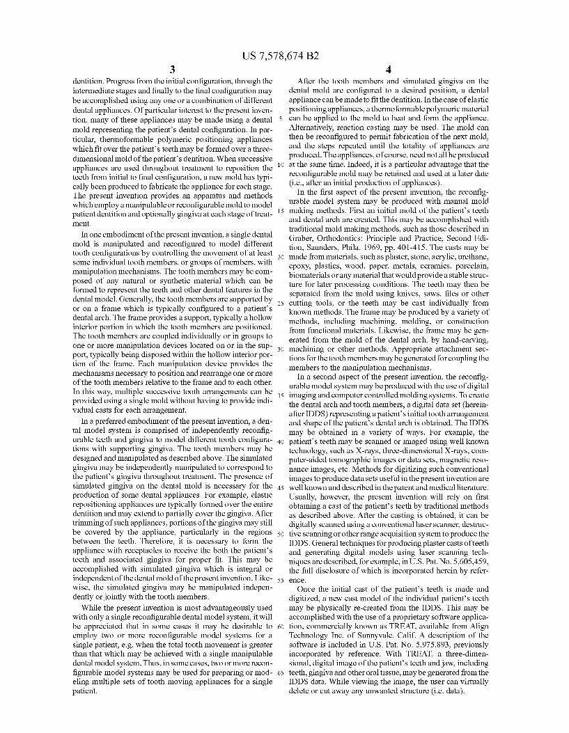
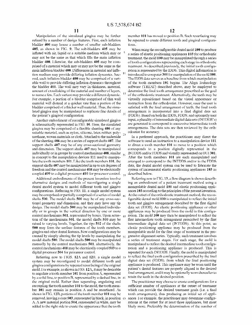
Produce initial impression of Scan or image patient's patient's dental features dental features
Produce mold of Scan or image mold Create DOS Impression
Separate tooth members from mold
Produce tooth Create attachment sections members, optionally on tooth members with attatchment
Sections
FIG. 3
US 7,578,674 B2 Sheet 4 of 9 Aug. 25, 2009 U.S. Patent
U.S. Patent Aug. 25, 2009 Sheet 5 Of 9 US 7,578,674 B2
S
CN O vs
s
U.S. Patent Aug. 25, 2009 Sheet 6 of 9 US 7,578,674 B2
101
FIG. 7
101
V2 &S-N-
400
s x, % 2
271 - M % p -- 2 P Af & Y201
b1 109 % 2 bé 2 404 É %
FG. 8
US 7,578,674 B2 Sheet 7 Of 9 Aug. 25, 2009 U.S. Patent
405
400
FIG. 9
101
406
407
408 F.G. 10
409
US 7,578,674 B2 Sheet 8 of 9 Aug. 25, 2009 U.S. Patent
504
503
FIG. 11
<r. O LO
F.G. 12B F.G. 12A
U.S. Patent Aug. 25, 2009 Sheet 9 Of 9 US 7,578,674 B2
Manipulate mold to reflect IDDS
Optionally produce appliance
Produce intermediate appliance - - - - - - - -
Manipulate mold to reflect FDDS
Produce final appliance
F.G. 13
US 7,578,674 B2 1.
METHODS FOR CORRECTING TOOTH MOVEMENTS MIDCOURSE IN TREATMENT
CROSS-REFERENCES TO RELATED APPLICATIONS
This application is a continuation of application Ser. No. 10/280,535, filed Oct. 24, 2002, which was a continuation of application Ser. No. 10/087,126, filed Feb. 28, 2002, which was a continuation of application Ser. No. 09/779,802, filed Feb. 7, 2001, now U.S. Pat. No. 6,394,801, which was a continuation of application Ser. No. 09/454,786, filed Dec. 3, 1999, now U.S. Pat. No. 6,227,851, which claimed the benefit and priority of U.S. Provisional Patent Application No. 60/110,868, filed Dec. 4, 1998, the full disclosures of which are hereby incorporated by reference for all purposes.
BACKGROUND OF THE INVENTION
The present invention is related generally to the field of orthodontics. More particularly, the present invention is related to a dental model system which can be manipulated to model a series of tooth configurations for a single patient throughout orthodontic treatment.
Orthodontic treatments involve repositioning misaligned teeth and improving bite configurations for improved cos metic appearance and dental function. Repositioning is accomplished by applying gentle controlled forces to the teeth over an extended period of time. Due to the limited space within the oral cavity and extensive movements that some teeth must undergo, the teeth will often be moved throughout a series of intermediate patterns to properly arrange the teeth. For example, molars may be temporarily distalized to create adequate space for movement of the inci sors. Thus, a single patient may experience an average of 25-30 stages or alignment patterns before achieving the final desired configuration.
Such repositioning may be accomplished with a variety of orthodontic treatments and dental appliances, including con ventional braces, spring retainers, positioners, and other removable aligners. With any treatment, an initial mold of the patient’s teeth is made. This mold provides a model of the patient’s teeth that the orthodontist uses to formulate a treat ment strategy. In some instances, it may be desirable to create additional molds of the patient’s teeth throughout the treat ment plan to reflect individual stages. For example, the treat ment strategy may be re-evaluated or a dental appliance may need to be fit to an intermediate tooth configuration. The need for intermediate tooth configuration molds is
particularly significant when using removable elastic appli ances to move the teeth. Such elastic appliances typically include a thin shell of elastic material that generally conforms to the pattern of a patient’s teeth, but is slightly out of align ment with the initial tooth configuration. By properly choos ing the alternate configuration, placement of the elastic appli ance over the teeth will move individual teeth to a desired position. Over time, multiple elastic appliances used in Suc cessive stages of treatment, will move the teeth to intermedi ate or final tooth positions. Such a system is described in U.S. Pat. No. 5,975,893, and in published PCT application WO 98/58596 which designates the United States and which is assigned to the assignee of the present application. Both these documents are incorporated by reference for all purposes. When using elastic appliances as described above, a series of appliances are made to reflect the Successive stages of treat
10
15
25
30
35
40
45
50
55
60
65
2 ment. Such appliances are typically made by heating and vacuum or pressure-sealing a sheet of thermoformable plastic over the dentition of a mold.
Traditional methods of dental mold making may be utilized to fabricate a mold for such use. These methods require first forming an impression of the patient's dentition using a Suit able impression material. Such as alginate or polyvinylsilox ane (PVS). Plaster is then poured into the impression to create a permanent, three-dimensional mold of the dentition. To create an appliance to reflect the next desired tooth configu ration in the series of treatment stages, a new mold must be created to reflect the desired configuration. This involves individually cutting the teeth from the mold and resetting the teeth in the desired configuration. Wax is then used to fill in the spaces and represent gingiva. This is a tedious process which compounds both cost and time of treatment for the patient. Resetting is accomplished by either taking into Ser Vice a laboratory technician or by sending the mold out to a dentallaboratory. This process typically requires 2.5 weeks to be accomplished. This represents lost time in the treatment plan as the patient cannot progress to the next stage of treat ment until a positioning appliance with the new desired con figuration is created. Since Such an orthodontic treatment may require, for example, 25 intermediate reset molds to represent 25 stages of treatment progress, the cost and time required for Such mold making may be prohibitively high. The process of iterative mold making may be improved
with the use of digital imaging and computer controlled molding systems. Here the patient's initial tooth arrangement and shape of the patient’s dental arch are represented by a digital data set. The data set can then be manipulated to reflect progressive tooth arrangements. For each arrangement, the data may be used to guide computerized model fabrication systems to create a corresponding three-dimensional mold. Such techniques may speed production time and reduce costs by eliminating the need for artistic resetting of teeth in mold manufacturing.
Although the above described process aids in the produc tion of iterative molds, further improvement may be desired. The cost in time and materials to produce each mold, though lessened, may still be significant. This cost is additive, as each new stage in treatment or each change in treatment requires the production of a new mold. Likewise, the cost of storing a series of molds for each patient throughout treatment may be formidable. In addition, it may be desirable to visualize a sequence of treatment stages, particularly in an academic environment or in a preliminary patient meeting.
For these reasons, it would be desirable to provide an alternative apparatus and methodology for realizing a series tooth configurations. Such apparatus and methods should be economical, reusable, reduce time consumption, reduce material waste, and, in particular, should reduce the need for fabricating multiple casts of teeth arrangements for stages in the orthodontic treatment. At least some of these objectives, as well as others, are met by the apparatus and methods of the invention described hereinafter.
BRIEF SUMMARY OF THE INVENTION
The present invention provides a manipulable or reconfig urable dental model system and methods for its use to model a series of tooth configurations corresponding to sequential tooth movements during an orthodontic treatment. When a patient undergoes orthodontic treatment, teeth and bite con figurations are realigned in a series of stages. Each stage represents a new pattern or dental configuration that will eventually lead to a proper final positioning of the entire
US 7,578,674 B2 3
dentition. Progress from the initial configuration, through the intermediate stages and finally to the final configuration may be accomplished using any one or a combination of different dental appliances. Of particular interest to the present inven tion, many of these appliances may be made using a dental 5 mold representing the patient’s dental configuration. In par ticular, thermoformable polymeric positioning appliances which fit over the patient’s teeth may be formed over a three dimensional mold of the patient’s dentition. When successive appliances are used throughout treatment to reposition the teeth from initial to final configuration, a new mold has typi cally been produced to fabricate the appliance for each stage. The present invention provides an apparatus and methods which employ a manipulable or reconfigurable mold to model patient dentition and optionally gingiva at each stage of treat ment.
10
15
In one embodiment of the present invention, a single dental mold is manipulated and reconfigured to model different tooth configurations by controlling the movement of at least Some individual tooth members, or groups of members, with manipulation mechanisms. The tooth members may be com posed of any natural or synthetic material which can be formed to represent the teeth and other dental features in the dental model. Generally, the tooth members are supported by or on a frame which is typically configured to a patients dental arch. The frame provides a Support, typically a hollow interior portion in which the tooth members are positioned. The tooth members are coupled individually or in groups to one or more manipulation devices located on or in the Sup port, typically being disposed within the hollow interior por tion of the frame. Each manipulation device provides the mechanisms necessary to position and rearrange one or more of the tooth members relative to the frame and to each other. In this way, multiple Successive tooth arrangements can be provided using a single mold without having to provide indi vidual casts for each arrangement.
25
30
35
In a preferred embodiment of the present invention, aden tal model system is comprised of independently reconfig urable teeth and gingiva to model different tooth configura- 40 tions with Supporting gingiva. The tooth members may be designed and manipulated as described above. The simulated gingiva may be independently manipulated to correspond to the patient’s gingiva throughout treatment. The presence of simulated gingiva on the dental mold is necessary for the 4s production of Some dental appliances. For example, elastic repositioning appliances are typically formed over the entire dentition and may extend to partially cover the gingiva. After trimming of such appliances, portions of the gingiva may still be covered by the appliance, particularly in the regions so between the teeth. Therefore, it is necessary to form the appliance with receptacles to receive the both the patients teeth and associated gingiva for proper fit. This may be accomplished with simulated gingiva which is integral or independent of the dental mold of the present invention. Like- ss wise, the simulated gingiva may be manipulated indepen dently or jointly with the tooth members.
While the present invention is most advantageously used with only a single reconfigurable dental model system, it will be appreciated that in some cases it may be desirable to 60 employ two or more reconfigurable model systems for a single patient, e.g. when the total tooth movement is greater than that which may be achieved with a single manipulable dental model system. Thus, in some cases, two or more recon figurable model systems may be used for preparing or mod- 65 eling multiple sets of tooth moving appliances for a single patient.
4 After the tooth members and simulated gingiva on the
dental mold are configured to a desired position, a dental appliance can be made to fit the dentition. In the case of elastic positioning appliances, athermoformable polymeric material can be applied to the mold to heat and form the appliance. Alternatively, reaction casting may be used. The mold can then be reconfigured to permit fabrication of the next mold, and the steps repeated until the totality of appliances are produced. The appliances, of course, need not all be produced at the same time. Indeed, it is a particular advantage that the reconfigurable mold may be retained and used at a later date (i.e., after an initial production of appliances).
In the first aspect of the present invention, the reconfig urable model system may be produced with manual mold making methods. First an initial mold of the patient’s teeth and dental arch are created. This may be accomplished with traditional mold making methods, such as those described in Graber, Orthodontics: Principle and Practice, Second Edi tion, Saunders, Phila. 1969, pp. 401-415. The casts may be made from materials, such as plaster, Stone, acrylic, urethane, epoxy, plastics, wood, paper, metals, ceramics, porcelain, biomaterials or any material that would provide a stable struc ture for later processing conditions. The teeth may then be separated from the mold using knives, saws, files or other cutting tools, or the teeth may be cast individually from known methods. The frame may be produced by a variety of methods, including machining, molding, or construction from functional materials. Likewise, the frame may be gen erated from the mold of the dental arch, by hand-carving, machining or other methods. Appropriate attachment sec tions for the tooth members may be generated for coupling the members to the manipulation mechanisms.
In a second aspect of the present invention, the reconfig urable model system may be produced with the use of digital imaging and computer controlled molding systems. To create the dental arch and tooth members, a digital data set (herein after IDDS) representing a patients initial tooth arrangement and shape of the patient’s dental arch is obtained. The IDDS may be obtained in a variety of ways. For example, the patient's teeth may be scanned or imaged using well known technology, such as X-rays, three-dimensional X-rays, com puter-aided tomographic images or data sets, magnetic reso nance images, etc. Methods for digitizing such conventional images to produce data sets useful in the present invention are well known and described in the patent and medical literature. Usually, however, the present invention will rely on first obtaining a cast of the patient’s teeth by traditional methods as described above. After the casting is obtained, it can be digitally scanned using a conventional laser scanner, destruc tive Scanning or other range acquisition system to produce the IDDS. General techniques for producing plaster casts ofteeth and generating digital models using laser Scanning tech niques are described, for example, in U.S. Pat. No. 5,605.459, the full disclosure of which is incorporated herein by refer CCC.
Once the initial cast of the patient’s teeth is made and digitized, a new cast model of the individual patient’s teeth may be physically re-created from the IDDS. This may be accomplished with the use of a proprietary Software applica tion, commercially known as TREAT, available from Align Technology Inc. of Sunnyvale, Calif. A description of the software is included in U.S. Pat. No. 5,975,893, previously incorporated by reference. With TREAT, a three-dimen sional, digital image of the patient’s teeth and jaw, including teeth, gingiva and other oral tissue, may be generated from the IDDS data. While viewing the image, the user can virtually delete or cut away any unwanted structure (i.e. data).

US 7,578,674 B2 5
The teeth and frame of the reconfigurable model system may be produced with the use of the IDDS data and TREAT software. Individual teeth may be virtually isolated by delet ing unwanted sections, such as Surrounding gingiva and the base of the originally scanned cast. Optionally, the data can be manipulated, deleted or added to create an attachment section on the tooth to be used for coupling to the manipulation mechanism. The resulting data may then be used to guide model fabrication systems, such as Stereolithography, CNC machining, laser machining, and other molding systems, to create molds of the individual tooth members. Similar meth odology may be used to produce the frame. In this case, the teeth may be virtually deleted to isolate the dental arch and other desired features. Specific design features in the frame may be created by manipulating, adding or deleting data. The resulting data may then be used to guide molding fabrication systems, such as stereolithography, CNC machining, laser machining, and other molding systems, to create the mold of the frame. In either case, the molded parts may be made from a variety of materials, including but not limited to plaster, stone, acrylic, urethane, epoxy, plastics, wood, paper, metals, ceramics, porcelain or biomaterials, that would provide a stable structure for later processing conditions.
In a third aspect of the present invention, the molded tooth members, generated by any of the above described methods, may be coupled to one or more manipulation mechanisms. The mechanisms are preferably disposed within the frame and are coupled to the tooth members for independently mov ing each tooth member between a plurality of discrete or continuous positions. The movements may range from one to six degrees of freedom. The movements may be achieved by manual actuation of a mechanism or they may be controlled by a microprocessor in accordance with a software code. Likewise, the movements may beachieved manually with the visual aide of computer graphics. In any case, the tooth mem bers may be manipulated to produce a series oftooth configu rations for use in a variety of orthodontic treatments. Such uses may include but are not limited to visualization for educational or descriptive purposes, production of a series of removable elastic positioning appliances, and production of other appliances for dental applications.
In a fourth aspect of the present invention, simulated gin giva may be present and may be manipulated to correspond to the patient's gingiva throughout treatment. Such simulated gingiva may be assembled with the tooth members and frame as an independent body, or it may be integral with the frame. Likewise, it may be manually manipulated or processor con trolled. Manual methods may typically involve applying a putty-type material to the frame Surrounding the tooth mem bers. Such material may be, but is not limited to, wax, silicone rubber or polysiloxane impression material. Once applied, the putty may be manipulated by hand to model the gingival configuration of the patient. When the dental model system is to be reconfigured, the putty may be partially or entirely removed and reapplied when the tooth members are arranged in the new configuration. Alternatively, the simulated gingiva may be comprised of inflatable bladders or pockets which may be pressure controlled by hand or by a processor. The bladder material may be any elastomeric material. Such as nylon, silicone, latex, polyurethane, or the like. The bladders may be present on the frame, Surrounding each tooth member. As the bladders are inflated, with air or a suitable liquid, the Surface geometry of the simulated gingival layer may be manipulated. In another embodiment, the simulated gingiva may be comprised of a flexible sheeting along the gingival line. Attached to the underside of the sheeting may be a series of support shafts which may be manipulated by hand or by a
10
15
25
30
35
40
45
50
55
60
65
6 processor. Such manipulation may alter the Surface geometry of the simulated gingival layer.
Additional embodiments of the present invention involve alternative designs and methods of reconfiguring a single dental model system to model different tooth and gingiva configurations. For example, a single model system may be comprised or partially comprised of a series of model shafts which may be manipulated individually or in the groups in the vertical direction by one or more mechanisms. The model shafts may be of any cross-sectional geometry and dimen Sion, and they may have any tip design. In an initial position, the tips of the model shafts may be positioned along a plane parallel to the gingival line. Upon actuation of a mechanism, the model shafts may be raised to varying levels, individually or in groups. Together, the tips of the shafts may form the Surface features of the tooth members, gingiva, and other dental features. Different tooth and gingival configurations may be accomplished by movement of the model shafts. In another example, a single dental model system may be recon figured to model different tooth and gingiva configurations by repeated resurfacing of the original mold. In this case, por tions of the original mold may be removed by manual meth ods, CNC machining, lasers or other material removal meth ods. Typically, such portions are Superficial, allowing the underlying Support structure to remain intact. Material may then be added to appropriate portions of the mold by manual methods, stereolithography, or other molding systems. Such resurfacing may be repeated to create different tooth and gingival configurations.
In a further aspect of the present invention, a method is provided for fabrication of a series of dental position adjust ment appliances. The method includes providing a dental model system having manipulable tooth members. One or more of the manipulable tooth members is then positioned into a first-tooth arrangement. At this point, a first appliance is formed with an impression from the mold with the teeth arranged in the first-tooth arrangement. After a first appliance is formed, one or more of the manipulable tooth members is positioned in a second-tooth arrangement. A second appli ance is then formed with an impression from the mold of the second-tooth arrangement. Additional Successive appliances can be formed at the same time and/or at one or more later times. An improved method for repositioning teeth is provided
using appliances, typically comprising polymeric shells, hav ing cavities shaped to receive and resiliently reposition teeth. The improvement includes determining at the outset of treat ment, a geometry for at least one appliance selected to move the teeth to a desired intermediate arrangement and at a later time (usually after the teeth have been moved through at least one, and usually at least two, three, four, five, or more stages) determining one or more geometries for at least one addi tional appliance having a geometry selected to move the teeth from an actual intermediate arrangement to a Successive intermediate or final tooth arrangement. The actual interme diate tooth arrangement may be determined by any available method, usually by taking a mold and optically scanning the mold, but optionally by direct optical or other scanning of the patient’s teeth.
BRIEF DESCRIPTION OF THE DRAWINGS
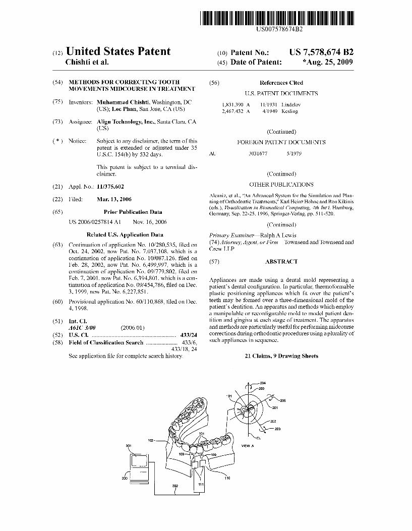
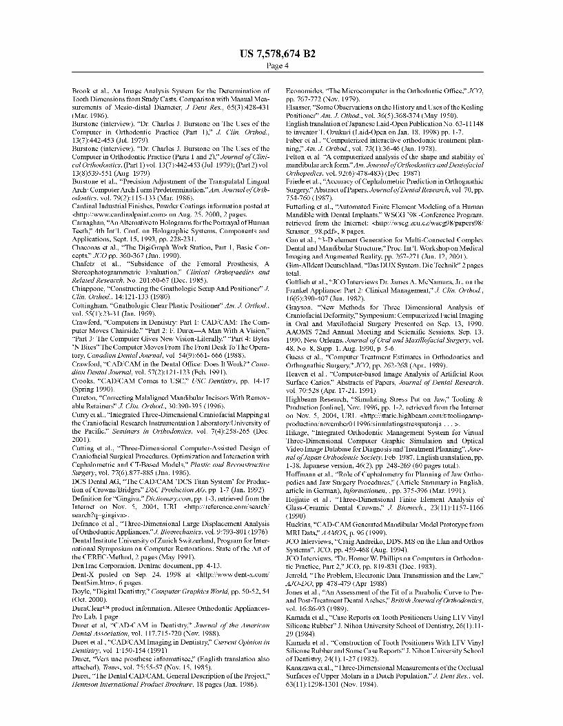
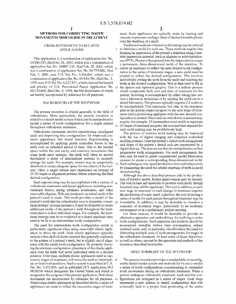
FIG. 1 is a simplified illustration of a reconfigurable dental model system and an elastic positioning appliance fabricated with its use.
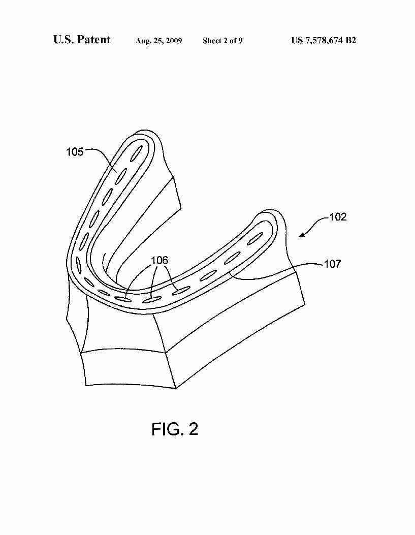
FIG. 2 is a perspective view of an embodiment of the frame of the present invention.
US 7,578,674 B2 7
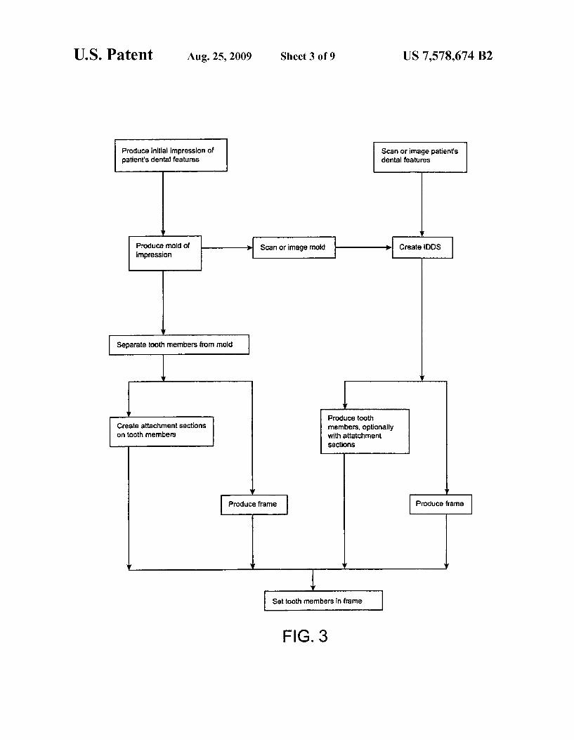
FIG. 3 is a flow diagram of production options for the dental model system.
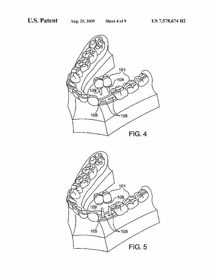
FIG. 4 illustrates an embodiment of arranging the tooth members in the frame by inserting the coupling members through the ports.
FIG. 5 illustrates an embodiment of arranging the tooth members in the frame by placing the tooth members on cou pling members protruding through the ports.
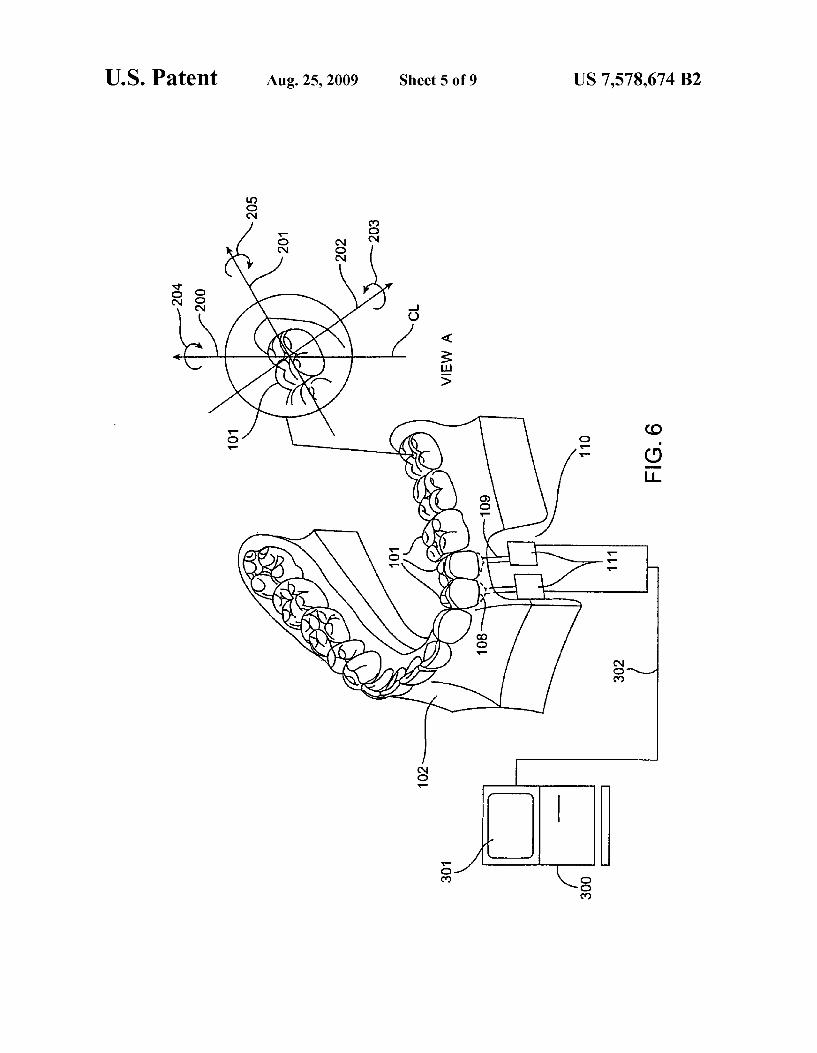
FIG. 6 is a simplified cut-away perspective view of the dental model system, revealing an embodiment of the manipulation devices, including View A which illustrates possible degrees of freedom in movement of each tooth mem ber.
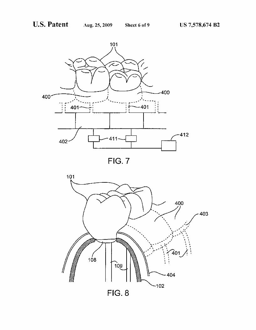
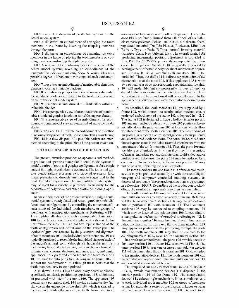
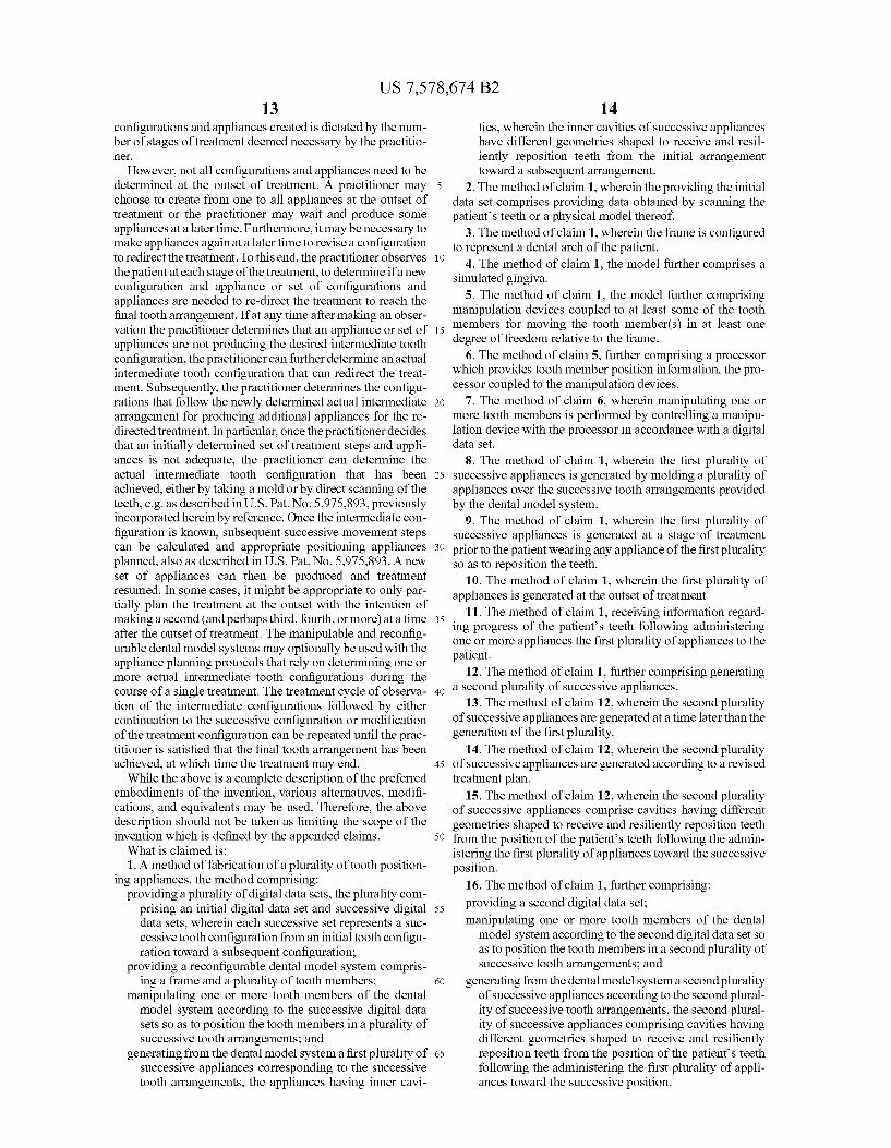
FIG. 7 illustrates an embodiment of manipulable simulated gingiva involving inflatable bladders.
FIG. 8 is a cut-away perspective view of an embodiment of the inflatable bladders in relation to the tooth members and frame of the dental model system.
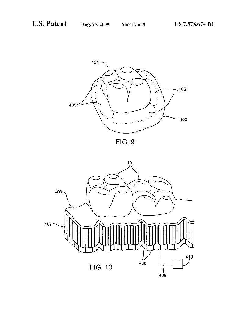
FIG. 9 illustrates an embodiment of sub-bladders within an inflatable bladder.
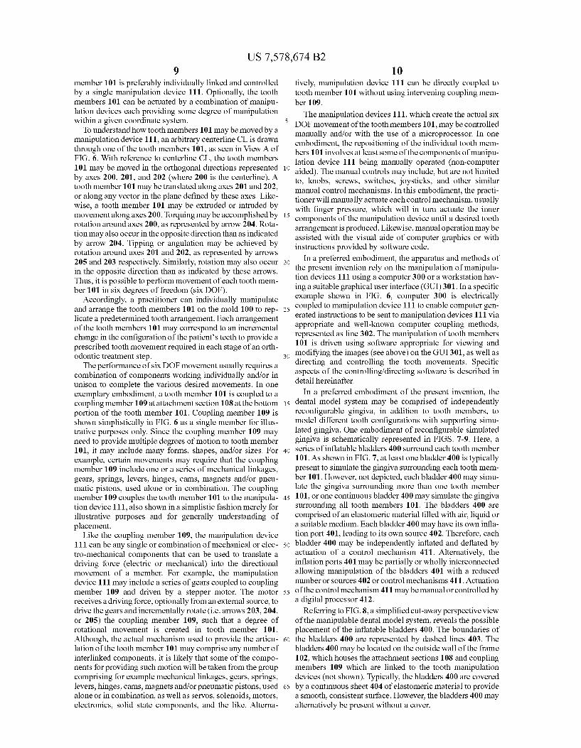
FIG.10 is a perspective view of an embodiment of manipu lable simulated gingiva involving movable Support shafts.
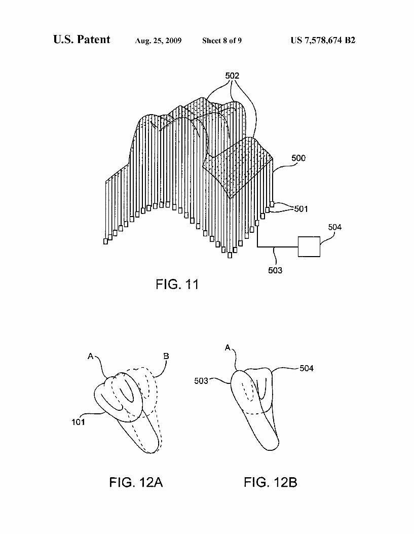
FIG. 11 is a perspective view of an embodiment of a recon figurable dental model system comprised of movable model shafts.
FIGS. 12A and 12B illustrate an embodiment of a method of reconfiguring a dental model system involving resurfacing.
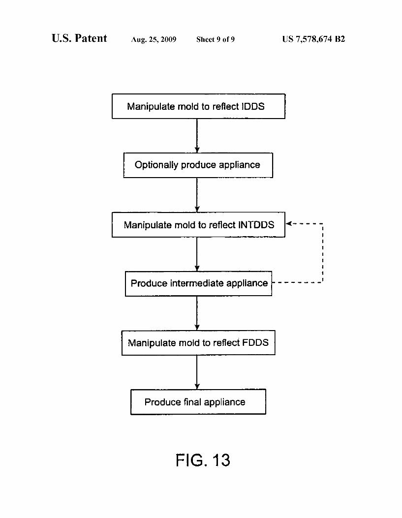
FIG. 13 is a flow diagram of a possible patient treatment method according to the principles of the present invention.
DETAILED DESCRIPTION OF THE INVENTION
The present invention provides an apparatus and methods to produce and operate a manipulable dental model system to model a series oftooth and gingiva configurations for a single patient throughout orthodontic treatment. The tooth and gin giva configurations represent each stage of treatment from initial presentation, through intermediate stages and to the final desired configuration. The manipulable model system may be used for a variety of purposes, particularly for the production of polymeric and other elastic positioning appli aCCS.
In one embodiment of the present invention, a single dental model system is manipulated and reconfigured to model dif ferent tooth configurations by controlling the movement of at least Some of the individual tooth members, or groups of members, with manipulation mechanisms. Referring to FIG. 1, a simplified illustration of such a manipulable dental mold 100 for the fabrication of dental appliances is shown. In this illustration, the mold 100 is a positive representation of the tooth configuration and dental arch of the lower jaw. The tooth configuration is created by the placement and alignment oftooth members 101. The individual tooth members 101 are typically produced to resemble the individual shape of each of the patient’s natural teeth. Although not shown, this may also include any type of dental feature, including but not limited to fillings, caps, crowns, dentures, implants, grafts, and dental appliances. In a preferred embodiment, the tooth members 101 are inserted into ports (not shown) in the frame 102 to Support the configuration. It is through these ports that the tooth members may be manipulated.
Also shown in FIG. 1 is a an exemplary dental appliance, specifically an elastic positioning appliance 103, which may be produced with use of the mold 100. The appliance 103 comprises a polymeric shell 104 having an inner cavity (not shown) on the underside of the shell 104 which is shaped to receive and resiliently reposition teeth from one tooth
10
15
25
30
35
40
45
50
55
60
65
8 arrangement to a Successive tooth arrangement. The appli ance 103 is preferably formed from a thin sheet of a suitable elastomeric polymer, such as Tru-Tain 0.03 in thermal form ing dental material (Tru-Tain Plastics, Rochester, Minn.), or Essix A-Type or Essix B-Type thermal forming material (Raintree-Essix, New Orleans, La.). The overall method for producing incremental position adjustment is provided in U.S. Pat. No. 5,975,893, previously incorporated by refer ence. But, in general, the shell 104 is typically produced by heating athermoformable polymer sheet and vacuum or pres sure forming the sheet over the tooth members 101 of the mold 100. Thus, the shell 104 is a direct representation of the characteristics of the mold 100. If this appliance 103 is worn by a patient as a stage in orthodontic repositioning, the shell 104 will preferably, but not necessarily, fit over all teeth or dental features supported by the patient’s dental arch. Those teeth which are to be repositioned will be slightly misfit by the appliance to allow force and movement into the desired posi tions. As described, the tooth members 101 are supported by a
frame 102, which houses the manipulation mechanisms. A preferred embodiment of the frame 102 is depicted in FIG. 2. The frame 102 is designed to have a hollow interior portion 105 and may include a plurality of ports 106 positioned hori Zontally along the gingival line 107 at locations which allow for placement of the tooth members 101. The positioning of the ports 106 is meant to correspond generally to the patients actual or desired tooth positions. The ports 106 are sized such that adequate space is available to avoid interference with the movement of the tooth members 101. Thus, the ports 106 may be oblong or elliptical, as shown, or they may form a variety of shapes, including rectangular, circular, multi-sided and/or multi-curved. Likewise, the ports 106 may be replaced by a continuous channel or track, or the interior portion 105 may not be present, obviating the need for ports. The tooth members 101 and frame 102 of the dental model
system may be produced manually or with the use of digital imaging and computer controlled molding systems, as described previously. These production options are presented in a flowchart, FIG. 3. Regardless of the production method ology, the resulting components may then be assembled. The tooth members 101 may be coupled to one or more
manipulation devices by any of a variety of means. Referring to FIG. 4, an attachment sections 108 may be present on a bottom portion of the tooth members 101. The attachment sections 108 may be connected to coupling members 109 which may be inserted through the ports 106 for coupling to a manipulation mechanism. Alternatively, referring to FIG. 5, the coupling member 109 may be integral with the manipu lation mechanism. In this case, the coupling members 109 may appear as posts or shafts protruding through the ports 106. The tooth members 101 may then be coupled to the coupling member 109 by means of an attachment section 108.
In a preferred embodiment, the ports 106 provide access to the inner portion 110 of frame 102, as shown in FIG. 6. The inner portion 110 houses one or more manipulation devices 111 which manipulate the tooth members 101. Once coupled to the manipulation devices 111, the tooth members 101 can be actuated and repositioned. The manipulation devices 111 are described in more detail below. The simplified cut-away view of dental mold 100 shown in
FIG. 6, reveals manipulation devices 111 disposed in the interior portion 110 of the frame 102. The manipulation device 111 can be a single mechanism, linked simultaneously to each individual tooth member 101 or group of members using, for example, a series of mechanical linkages or other similar means. However, as shown in FIG. 6, each tooth
US 7,578,674 B2
member 101 is preferably individually linked and controlled by a single manipulation device 111. Optionally, the tooth members 101 can be actuated by a combination of manipu lation devices each providing some degree of manipulation within a given coordinate system.
To understand how tooth members 101 may be moved by a manipulation device 111, an arbitrary centerline CL is drawn through one of the tooth members 101, as seen in View A of FIG. 6. With reference to centerline CL, the tooth members 101 may be moved in the orthogonal directions represented by axes 200, 201, and 202 (where 200 is the centerline). A tooth member 101 may be translated along axes 201 and 202, or along any vector in the plane defined by these axes. Like wise, a tooth member 101 may be extruded or intruded by movementalong axes 200. Torquing may be accomplished by rotation around axes 200, as represented by arrow 204. Rota tion may also occur in the opposite direction than as indicated by arrow 204. Tipping or angulation may be achieved by rotation around axes 201 and 202, as represented by arrows 205 and 203 respectively. Similarly, rotation may also occur in the opposite direction than as indicated by these arrows. Thus, it is possible to perform movement of each tooth mem ber 101 in six degrees of freedom (six DOF).
Accordingly, a practitioner can individually manipulate and arrange the tooth members 101 on the mold 100 to rep licate a predetermined tooth arrangement. Each arrangement of the tooth members 101 may correspond to an incremental change in the configuration of the patient's teeth to provide a prescribed tooth movement required in each stage of an orth odontic treatment step. The performance of six DOF movement usually requires a
combination of components working individually and/or in unison to complete the various desired movements. In one exemplary embodiment, a tooth member 101 is coupled to a coupling member 109 at attachment section 108 at the bottom portion of the tooth member 101. Coupling member 109 is shown simplistically in FIG. 6 as a single member for illus trative purposes only. Since the coupling member 109 may need to provide multiple degrees of motion to tooth member 101, it may include many forms, shapes, and/or sizes. For example, certain movements may require that the coupling member 109 include one or a series of mechanical linkages, gears, springs, levers, hinges, cams, magnets and/or pneu matic pistons, used alone or in combination. The coupling member 109 couples the tooth member 101 to the manipula tion device 111, also shown in a simplistic fashion merely for illustrative purposes and for generally understanding of placement.
Like the coupling member 109, the manipulation device 111 can be any single or combination of mechanical or elec tro-mechanical components that can be used to translate a driving force (electric or mechanical) into the directional movement of a member. For example, the manipulation device 111 may include a series of gears coupled to coupling member 109 and driven by a stepper motor. The motor receives a driving force, optionally from an external Source, to drive the gears and incrementally rotate (i.e. arrows 203, 204, or 205) the coupling member 109, such that a degree of rotational movement is created in tooth member 101. Although, the actual mechanism used to provide the articu lation of the tooth member 101 may comprise any number of interlinked components, it is likely that some of the compo nents for providing Such motion will be taken from the group comprising for example mechanical linkages, gears, springs, levers, hinges, cams, magnets and/or pneumatic pistons, used alone or in combination, as well as servos, Solenoids, motors, electronics, Solid state components, and the like. Alterna
10
15
25
30
35
40
45
50
55
60
65
10 tively, manipulation device 111 can be directly coupled to tooth member 101 without using intervening coupling mem ber 109.
The manipulation devices 111, which create the actual six DOF movement of the tooth members 101, may be controlled manually and/or with the use of a microprocessor. In one embodiment, the repositioning of the individual tooth mem bers 101 involves at least some of the components of manipu lation device 111 being manually operated (non-computer aided). The manual controls may include, but are not limited to, knobs, screws, Switches, joysticks, and other similar manual control mechanisms. In this embodiment, the practi tioner will manually actuate each control mechanism, usually with finger pressure, which will in turn actuate the inner components of the manipulation device until a desired tooth arrangement is produced. Likewise, manual operation may be assisted with the visual aide of computer graphics or with instructions provided by software code.
In a preferred embodiment, the apparatus and methods of the present invention rely on the manipulation of manipula tion devices 111 using a computer 300 or a workstation hav ing a suitable graphical user interface (GUI)301. In a specific example shown in FIG. 6, computer 300 is electrically coupled to manipulation device 111 to enable computer gen erated instructions to be sent to manipulation devices 111 via appropriate and well-known computer coupling methods, represented as line 302. The manipulation of tooth members 101 is driven using software appropriate for viewing and modifying the images (see above) on the GUI 301, as well as directing and controlling the tooth movements. Specific aspects of the controlling/directing software is described in detail hereinafter.
In a preferred embodiment of the present invention, the dental model system may be comprised of independently reconfigurable gingiva, in addition to tooth members, to model different tooth configurations with Supporting simu lated gingiva. One embodiment of reconfigurable simulated gingiva is schematically represented in FIGS. 7-9. Here, a series of inflatable bladders 400 surround each tooth member 101. As shown in FIG. 7, at least one bladder 400 is typically present to simulate the gingiva Surrounding each tooth mem ber 101. However, not depicted, each bladder 400 may simu late the gingiva Surrounding more than one tooth member 101, or one continuous bladder 400 may simulate the gingiva surrounding all tooth members 101. The bladders 400 are comprised of an elastomeric material filled with air, liquid or a suitable medium. Each bladder 400 may have its own infla tion port 401, leading to its own source 402. Therefore, each bladder 400 may be independently inflated and deflated by actuation of a control mechanism 411. Alternatively, the inflation ports 401 may be partially or wholly interconnected allowing manipulation of the bladders 401 with a reduced number or sources 402 or control mechanisms 411. Actuation of the control mechanism 411 may be manual or controlled by a digital processor 412.
Referring to FIG. 8, a simplified cut-away perspective view of the manipulable dental model system, reveals the possible placement of the inflatable bladders 400. The boundaries of the bladders 400 are represented by dashed lines 403. The bladders 400 may be located on the outside wall of the frame 102, which houses the attachment sections 108 and coupling members 109 which are linked to the tooth manipulation devices (not shown). Typically, the bladders 400 are covered by a continuous sheet 404 of elastomeric material to provide a smooth, consistent surface. However, the bladders 400 may alternatively be present without a cover.
US 7,578,674 B2 11
Manipulation of the simulated gingiva may be further refined by a number of design features. First, each inflation bladder 400 may house a number of smaller sub-bladders 405, as shown in FIG. 9. The sub-bladders 405 may be inflated with air, liquid or a suitable medium which may or may not be the same as that which fills the main inflation bladder 400. Likewise, the sub-bladders 405 may be com prised of a material which may or may not be the same as the main inflation bladder 400. Differences in material and infla tion medium may provide differing inflation dynamics. Sec ond, each inflation bladder 400 may be comprised of a vari able wall to provide differing inflation dynamics throughout the bladder 400. The wall may vary in thickness, material, amount of crosslinking of the material and number of layers, to name a few. Each variant may provide a different dynamic. For example, a portion of a bladder comprised of thin wall material will distend at a quicker rate than a portion of the bladder comprised of a thicker wall material. Thus, the simu lated gingiva may be manipulated to replicate fine details of the patient’s gingival configuration.
Another embodiment of reconfigurable simulated gingiva is schematically represented in FIG. 10. Here, the simulated gingiva may be comprised of a flexible sheeting 406 of any Suitable material. Such as nylon, silicone, latex rubber, poly urethane, woven materials or cloth. Attached to the underside of the sheeting 406 may be a series of support shafts 407. The Support shafts 407 may be of any cross-sectional geometry and dimension. The support shafts 407 may be manipulated individually or in groups by control mechanisms 408, similar in concept to the manipulation devices 111 used to manipu late the tooth members 101. Like the tooth members 101, the Support shafts 407 may be manipulated in up to six degrees of freedom and the control mechanisms 408 may be electrically coupled 409 to a digital processor 410 for processor control.
Additional embodiments of the present invention involve alternative designs and methods of reconfiguring a single dental model system to model different tooth and gingiva configurations. Referring to FIG. 11, a single model system may be comprised or partially comprised of a series of model shafts 500. The model shafts 500 may be of any cross-sec tional geometry and dimension, and they may have any tip design. The model shafts 500 may be manipulated individu ally or in groups in the vertical direction by one or more control mechanisms 501, represented by boxes. Upon actua tion of the mechanisms 501, the model shafts 500 may be raised to varying levels. Together, the tips 502 of the shafts 500 may form the surface features of the tooth members, gingiva and other dental features. New configurations may be created by simply altering the tip levels by manipulating the model shafts 500. The model shafts 500 may be manipulated manually by the control mechanisms 501. alternatively, the control mechanisms 408 may be electrically coupled 503 to a digital processor 504 for processor control.
Referring now to FIGS. 12A and 12B, a single model system may be reconfigured to model different tooth and gingiva configurations by repeated resurfacing of the original mold. For example, as shown in FIG. 12A, it may be desirable to angulate a tooth member 101 from position A, represented by a solid line, to position B, represented by a dashed line, in the original mold. Rather than separating, angulating and recoupling the tooth member 101 to the mold, the tooth mem ber 101 may remain in position A and be resurfaced. As shown in FIG.12B, portions of the tooth member 101 may be removed, leaving a core 503, represented in black, in position A. A new material portion 504, represented in white, may be added to the right side to create the appearance that the tooth
10
15
25
30
35
40
45
50
55
60
65
12 member 101 has moved to position B. Such resurfacing may be repeated to create different tooth and gingival configura tions.
When using the reconfigurable dental mold 100 to produce a series of elastic positioning appliances 103 for orthodontic treatment, the mold 100 may be manipulated through a series oftooth configurations representing each stage in orthodontic treatment. As described previously, the initial tooth configu ration is represented by the IDDS. This digital information is introduced to computer 300 for manipulation of the mold 100. The IDDS data serves as a baseline from which manipulation of the tooth members 101 begins. The Align Technology software (TREAT) described above, may be employed to determine the final tooth arrangement prescribed as the goal of the orthodontic treatment. Alternatively, the teeth may be virtually repositioned based on the visual appearance or instruction from the orthodontist. However, once the user is satisfied with the final arrangement of teeth, the final tooth arrangement is incorporated into a final digital data set (FDDS). Based on both the IDDS, FDDS, and optionally user input, a plurality of intermediate digital data sets (INTDDS’s) are generated to correspond to Successive intermediate tooth arrangements. The data sets are then reviewed by the orth odontist for accuracy.
In a preferred approach, the practitioner may direct the Software to send an instruction to a manipulation device 111 to direct a tooth member 101 to move to a position which corresponds to a position digitally represented in the INTDDS and/or FDDS and visually represented on GUI 301. After the tooth members 101 are each manipulated and arranged to correspond to the INTDDS and/or to the FDDS data, the dental model system can be used to fabricate the system of incremental elastic positioning appliances 103 as described below.
Referring now to FIG. 13, a flow diagram is shown describ ing an embodiment of a patient treatment method using a manipulable dental mold 100 and elastic positioning appli ances 103 according to the principles of the present invention. At the outset of the orthodontic treatment method, the recon figurable dental mold 100 is manipulated to reflect the initial tooth and gingiva arrangement described by the first digital data set (IDDS). An elastic positioning appliance or other appliances may be produced from the mold in this configu ration. The mold 100 may then be manipulated to reflect the first intermediate tooth arrangement prescribed by the first intermediate digital data set (INTDDS). At this point, an elastic positioning appliance may be produced from the manipulable mold for the first stage of treatment in the pro gressive alignment series. Typically, Such treatment involves a series of treatment stages. For each stage, the mold is manipulated to reflect the desired intermediate tooth configu ration and a positioning appliance is produced. This is repeated for each INTDDS. Finally, the mold is manipulated to reflect the final tooth configuration prescribed by the final digital data set (FDDS), from which the final positioning appliance is produced. This appliance may be worn until the patient’s dental features are properly aligned in the desired final arrangement, and it may be optionally worn thereafter to retain the teeth in the desired position. The practitioner may choose to create configurations for a
sufficient number of appliances at the outset of treatment which can provide the desired treatment goals (i.e. a final tooth arrangement), thus producing an initial set of appli ances. For example, the practitioner may determine configu rations at the outset for at least three appliances, but most likely more. Preferably the determination of the number of
US 7,578,674 B2 13
configurations and appliances created is dictated by the num ber of stages of treatment deemed necessary by the practitio
.
However, not all configurations and appliances need to be determined at the outset of treatment. A practitioner may choose to create from one to all appliances at the outset of treatment or the practitioner may wait and produce some appliances at a latertime. Furthermore, it may be necessary to make appliances again at a later time to revise a configuration to redirect the treatment. To this end, the practitioner observes the patient at each stage of the treatment, to determine ifa new configuration and appliance or set of configurations and appliances are needed to re-direct the treatment to reach the final tooth arrangement. If at any time after making an obser Vation the practitioner determines that an appliance or set of appliances are not producing the desired intermediate tooth configuration, the practitioner can further determine an actual intermediate tooth configuration that can redirect the treat ment. Subsequently, the practitioner determines the configu rations that follow the newly determined actual intermediate arrangement for producing additional appliances for the re directed treatment. In particular, once the practitioner decides that an initially determined set of treatment steps and appli ances is not adequate, the practitioner can determine the actual intermediate tooth configuration that has been achieved, either by taking a mold or by direct Scanning of the teeth, e.g. as described in U.S. Pat. No. 5,975,893, previously incorporated herein by reference. Once the intermediate con figuration is known, Subsequent Successive movement steps can be calculated and appropriate positioning appliances planned, also as described in U.S. Pat. No. 5,975,893. A new set of appliances can then be produced and treatment resumed. In some cases, it might be appropriate to only par tially plan the treatment at the outset with the intention of making a second (and perhaps third, fourth, or more) at a time after the outset of treatment. The manipulable and reconfig urable dental model systems may optionally be used with the appliance planning protocols that rely on determining one or more actual intermediate tooth configurations during the course of a single treatment. The treatment cycle of observa tion of the intermediate configurations followed by either continuation to the Successive configuration or modification of the treatment configuration can be repeated until the prac titioner is satisfied that the final tooth arrangement has been achieved, at which time the treatment may end.
While the above is a complete description of the preferred embodiments of the invention, various alternatives, modifi cations, and equivalents may be used. Therefore, the above description should not be taken as limiting the scope of the invention which is defined by the appended claims. What is claimed is: 1. A method of fabrication of a plurality of tooth position
ing appliances, the method comprising: providing a plurality of digital data sets, the plurality com
prising an initial digital data set and Successive digital data sets, wherein each Successive set represents a Suc cessive tooth configuration from an initial tooth configu ration toward a Subsequent configuration;
providing a reconfigurable dental model system compris ing a frame and a plurality of tooth members;
manipulating one or more tooth members of the dental model system according to the Successive digital data sets so as to position the tooth members in a plurality of Successive tooth arrangements; and
generating from the dental model system a first plurality of Successive appliances corresponding to the Successive tooth arrangements, the appliances having inner cavi
5
10
15
25
30
35
40
45
50
55
60
65
14 ties, wherein the inner cavities of Successive appliances have different geometries shaped to receive and resil iently reposition teeth from the initial arrangement toward a Subsequent arrangement.
2. The method of claim 1, wherein the providing the initial data set comprises providing data obtained by Scanning the patient’s teeth or a physical model thereof.
3. The method of claim 1, wherein the frame is configured to represent a dental arch of the patient.
4. The method of claim 1, the model further comprises a simulated gingiva.
5. The method of claim 1, the model further comprising manipulation devices coupled to at least Some of the tooth members for moving the tooth member(s) in at least one degree of freedom relative to the frame.
6. The method of claim 5, further comprising a processor which provides tooth member position information, the pro cessor coupled to the manipulation devices.
7. The method of claim 6, wherein manipulating one or more tooth members is performed by controlling a manipu lation device with the processor in accordance with a digital data set.
8. The method of claim 1, wherein the first plurality of Successive appliances is generated by molding a plurality of appliances over the Successive tooth arrangements provided by the dental model system.
9. The method of claim 1, wherein the first plurality of Successive appliances is generated at a stage of treatment prior to the patient wearing any appliance of the first plurality So as to reposition the teeth.
10. The method of claim 1, wherein the first plurality of appliances is generated at the outset of treatment.
11. The method of claim 1, receiving information regard ing progress of the patient's teeth following administering one or more appliances the first plurality of appliances to the patient.
12. The method of claim 1, further comprising generating a second plurality of Successive appliances.
13. The method of claim 12, wherein the second plurality of successive appliances are generated at a time later than the generation of the first plurality.
14. The method of claim 12, wherein the second plurality of successive appliances are generated according to a revised treatment plan.
15. The method of claim 12, wherein the second plurality of Successive appliances comprise cavities having different geometries shaped to receive and resiliently reposition teeth from the position of the patient’s teeth following the admin istering the first plurality of appliances toward the Successive position.
16. The method of claim 1, further comprising: providing a second digital data set; manipulating one or more tooth members of the dental
model system according to the second digital data set So as to position the tooth members in a second plurality of Successive tooth arrangements; and
generating from the dental model system a second plurality of successive appliances according to the second plural ity of Successive tooth arrangements, the second plural ity of Successive appliances comprising cavities having different geometries shaped to receive and resiliently reposition teeth from the position of the patient’s teeth following the administering the first plurality of appli ances toward the Successive position.
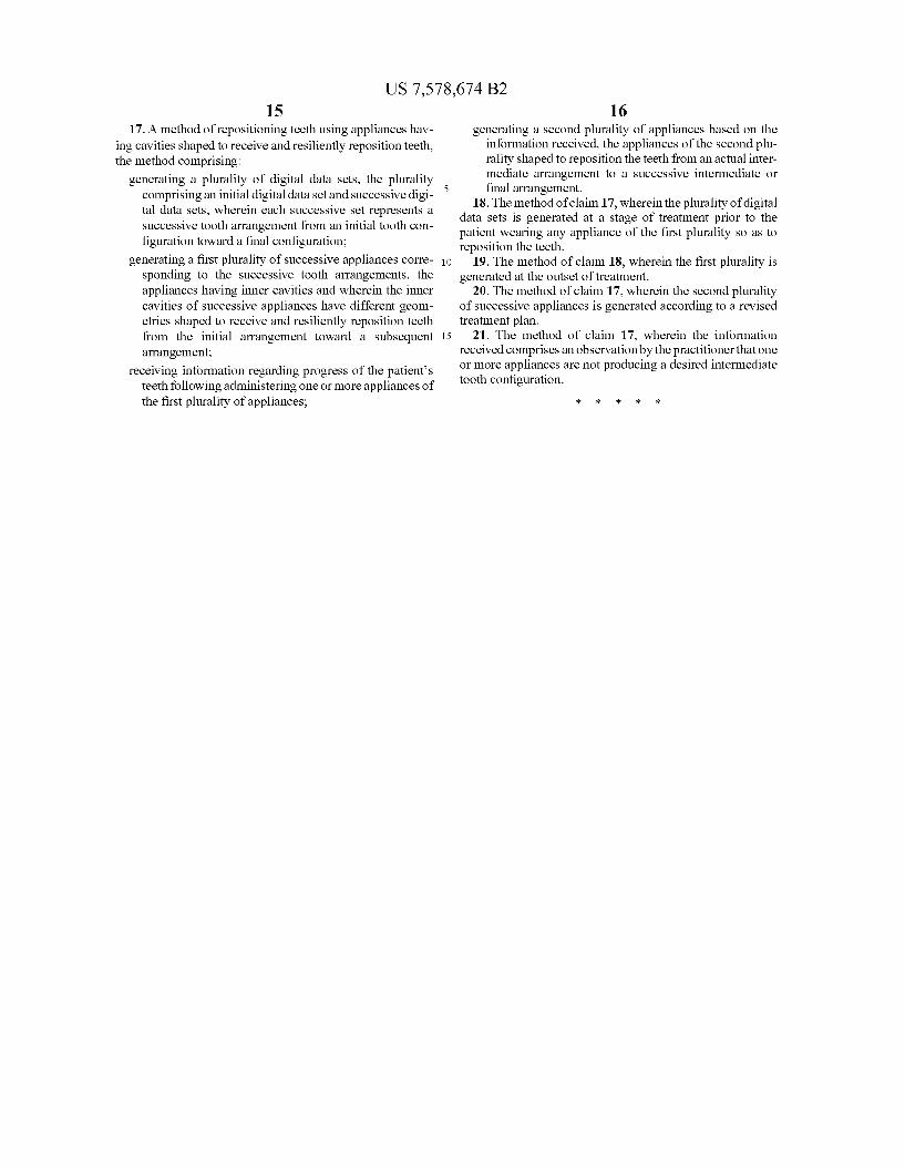
US 7,578,674 B2 15
17. A method of repositioning teeth using appliances hav ing cavities shaped to receive and resiliently reposition teeth, the method comprising:
generating a plurality of digital data sets, the plurality comprising an initial digital data set and Successive digi tal data sets, wherein each Successive set represents a Successive tooth arrangement from an initial tooth con figuration toward a final configuration;
generating a first plurality of Successive appliances corre sponding to the Successive tooth arrangements, the appliances having inner cavities and wherein the inner cavities of Successive appliances have different geom etries shaped to receive and resiliently reposition teeth from the initial arrangement toward a Subsequent arrangement;
receiving information regarding progress of the patients teeth following administering one or more appliances of the first plurality of appliances;
5
10
15
16 generating a second plurality of appliances based on the
information received, the appliances of the second plu rality shaped to reposition the teeth from an actual inter mediate arrangement to a successive intermediate or final arrangement.
18. The method of claim 17, wherein the plurality of digital data sets is generated at a stage of treatment prior to the patient wearing any appliance of the first plurality So as to reposition the teeth.
19. The method of claim 18, wherein the first plurality is generated at the outset of treatment.
20. The method of claim 17, wherein the second plurality of Successive appliances is generated according to a revised treatment plan.
21. The method of claim 17, wherein the information received comprises an observation by the practitioner that one or more appliances are not producing a desired intermediate tooth configuration.
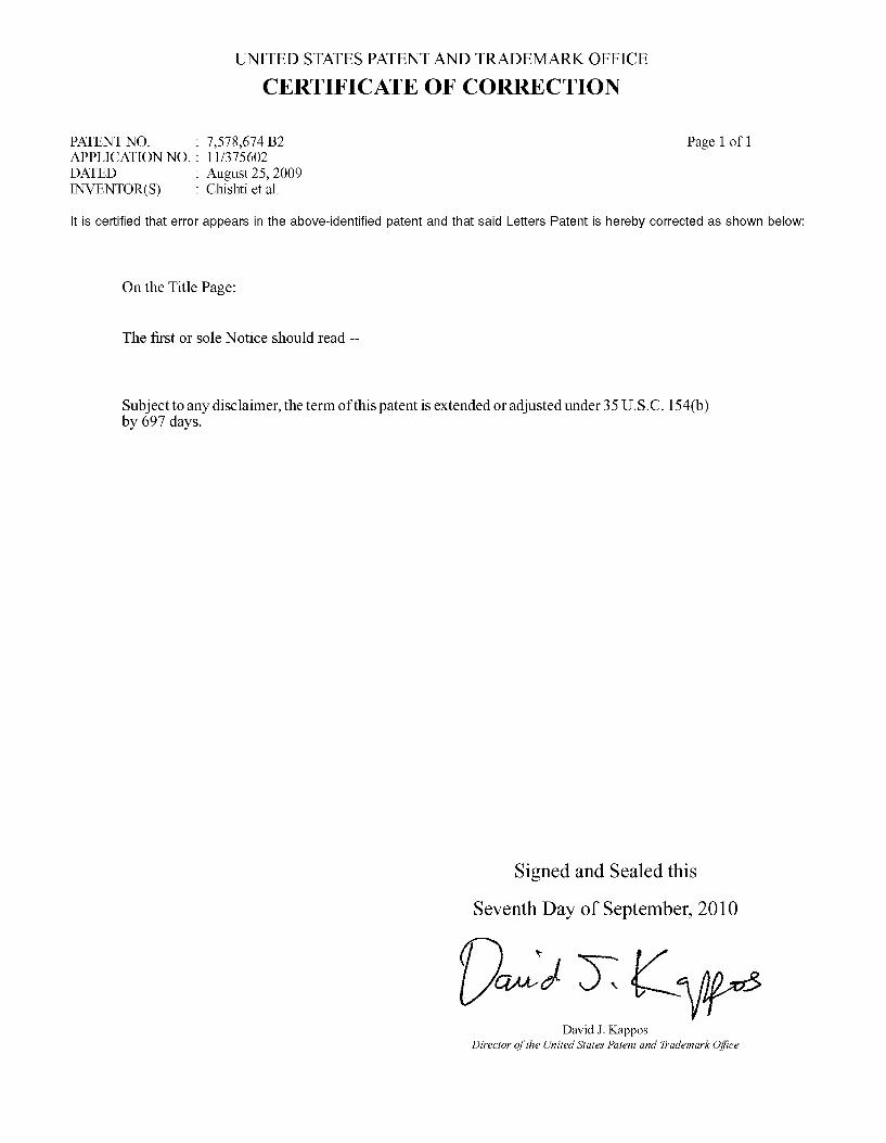
UNITED STATES PATENT AND TRADEMARK OFFICE
CERTIFICATE OF CORRECTION
PATENT NO. : 7,578,674 B2 Page 1 of 1 APPLICATION NO. : 1 1/375602 DATED : August 25, 2009 INVENTOR(S) : Chishti et al.
It is certified that error appears in the above-identified patent and that said Letters Patent is hereby corrected as shown below:
On the Title Page:
The first or sole Notice should read --
Subject to any disclaimer, the term of this patent is extended or adjusted under 35 U.S.C. 154(b) by 697 days.
Signed and Sealed this
Seventh Day of September, 2010
David J. Kappos Director of the United States Patent and Trademark Office