Embed Size (px)
Citation preview

12. TCA ConneCTors
The TCA connectors have been specifically developed for the next
generation of telecom, medical and industrial applications. The compact
connector allows the transmission of highest data rates. Thanks to the
innovative GuideSpring concept, the direct plug-in of a PCB is possible
without any safety loss. Additionally, a corresponding module connector is
available for robust applications. The power connector offers power contacts
with the current carrying capacity of up to 16 A as well as contacts for signal
transmission. HARTING offers application-specific design-in support for the
connectors, as well as the system analysis support.
Boardto
Board
Cable/Wire
toBoard
IP 20 IP 65 / IP 67
Data Signal PowerData
transfer rate
shielding number of contacts, contact density
Voltage, working current
Cable termination
Han- Quick Lock®
IDC Crimp
Screw Cage clamp
Axial screw
PCB termination
THT SMC SMT
Press-in
Application standard
Separate housing
Integratedhousing
high performance
Housing integration
ConneCtion type environment AppliCAtion
App l icat ion prof i le:

TCA
1201
12. TCA ConneCTors
ContentS PAge
Introduction 12.02
General information 12.04
12.06
AdvancedMC™ connectors for AdvancedTCA® 12.08
Power connectors for AdvancedTCA® 12.10
AdvancedMC™ connectors for MicroTCA™ 12.12
Power output connectors for MicroTCA™ 12.14
Plug connectors for AdvancedMC™ modules 12.17
Plug connectors for MCH modules 12.22
1202
TCA
12. TCA ConneCTors
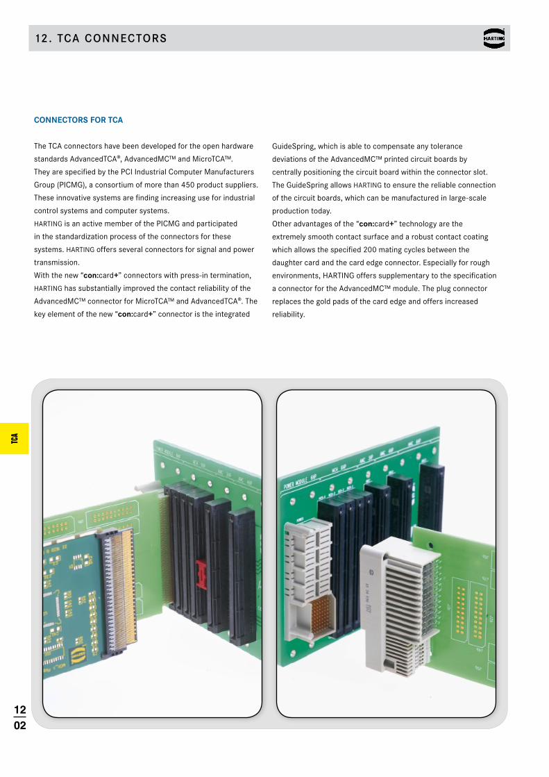
GuideSpring, which is able to compensate any tolerance
deviations of the AdvancedMC™ printed circuit boards by
centrally positioning the circuit board within the connector slot.
The GuideSpring allows HARTING to ensure the reliable connection
of the circuit boards, which can be manufactured in large-scale
production today.
Other advantages of the “con:card+” technology are the
extremely smooth contact surface and a robust contact coating
which allows the specified 200 mating cycles between the
daughter card and the card edge connector. Especially for rough
environments, HARTING offers supplementary to the specification
a connector for the AdvancedMC™ module. The plug connector
replaces the gold pads of the card edge and offers increased
reliability.
ConneCtorS for tCA
The TCA connectors have been developed for the open hardware
standards AdvancedTCA®, AdvancedMC™ and MicroTCA™.
They are specified by the PCI Industrial Computer Manufacturers
Group (PICMG), a consortium of more than 450 product suppliers.
These innovative systems are finding increasing use for industrial
control systems and computer systems.
HARTING is an active member of the PICMG and participated
in the standardization process of the connectors for these
systems. HARTING offers several connectors for signal and power
transmission.
With the new “con:card+” connectors with press-in termination,
HARTING has substantially improved the contact reliability of the
AdvancedMC™ connector for MicroTCA™ and AdvancedTCA®. The
key element of the new “con:card+” connector is the integrated
1203
TCA
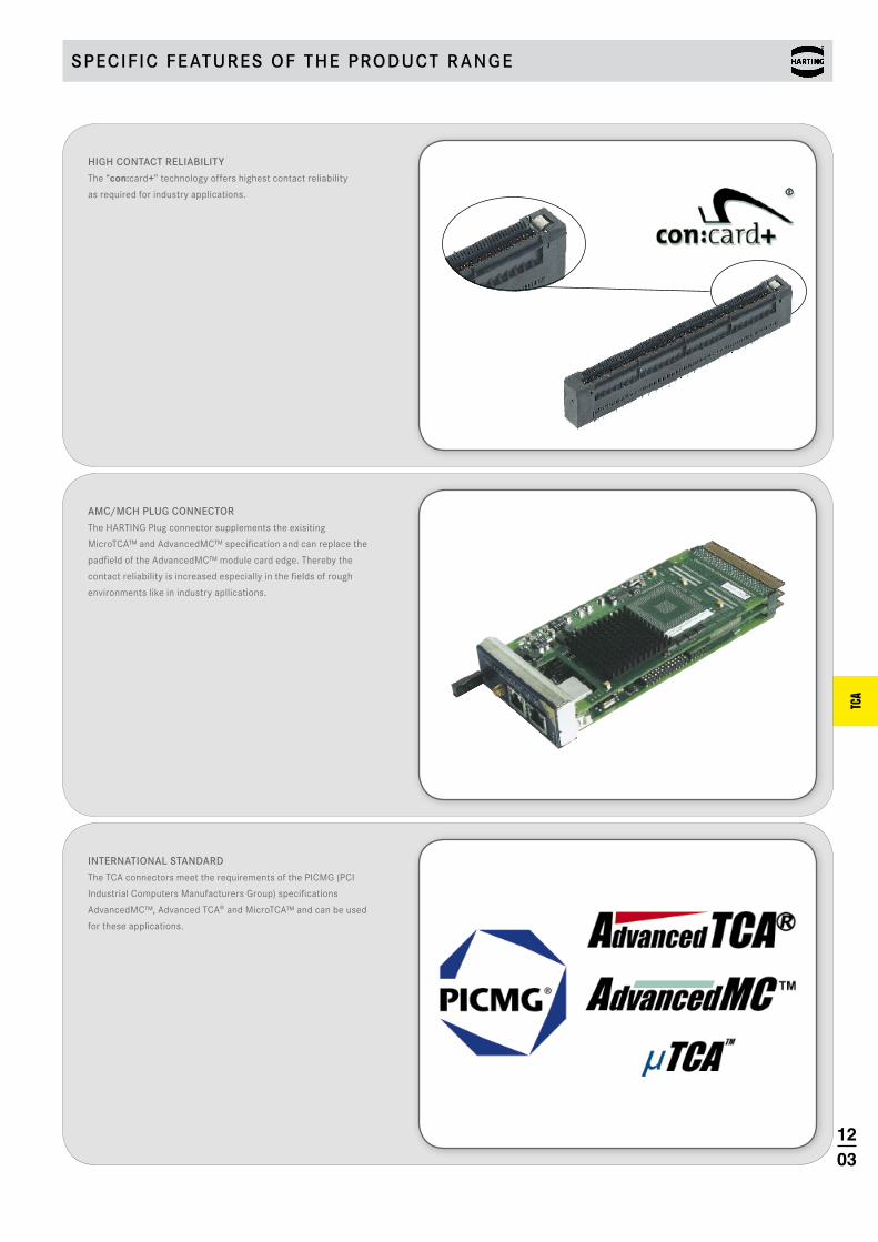
InTernATIonAl sTAnDArD
The TCA connectors meet the requirements of the PICMG (PCI
Industrial Computers Manufacturers Group) specifications
AdvancedMC™, Advanced TCA® and MicroTCA™ and can be used
for these applications.
HIgH ConTACT relIABIlITy
The “con:card+” technology offers highest contact reliability
as required for industry applications.
AMC/MCH Plug ConneCTor
The HARTING Plug connector supplements the exisiting
MicroTCA™ and AdvancedMC™ specification and can replace the
padfield of the AdvancedMC™ module card edge. Thereby the
contact reliability is increased especially in the fields of rough
environments like in industry apllications.
sPeCIfIC feATures of THe ProDuCT r Ange
1204
TCA
General information
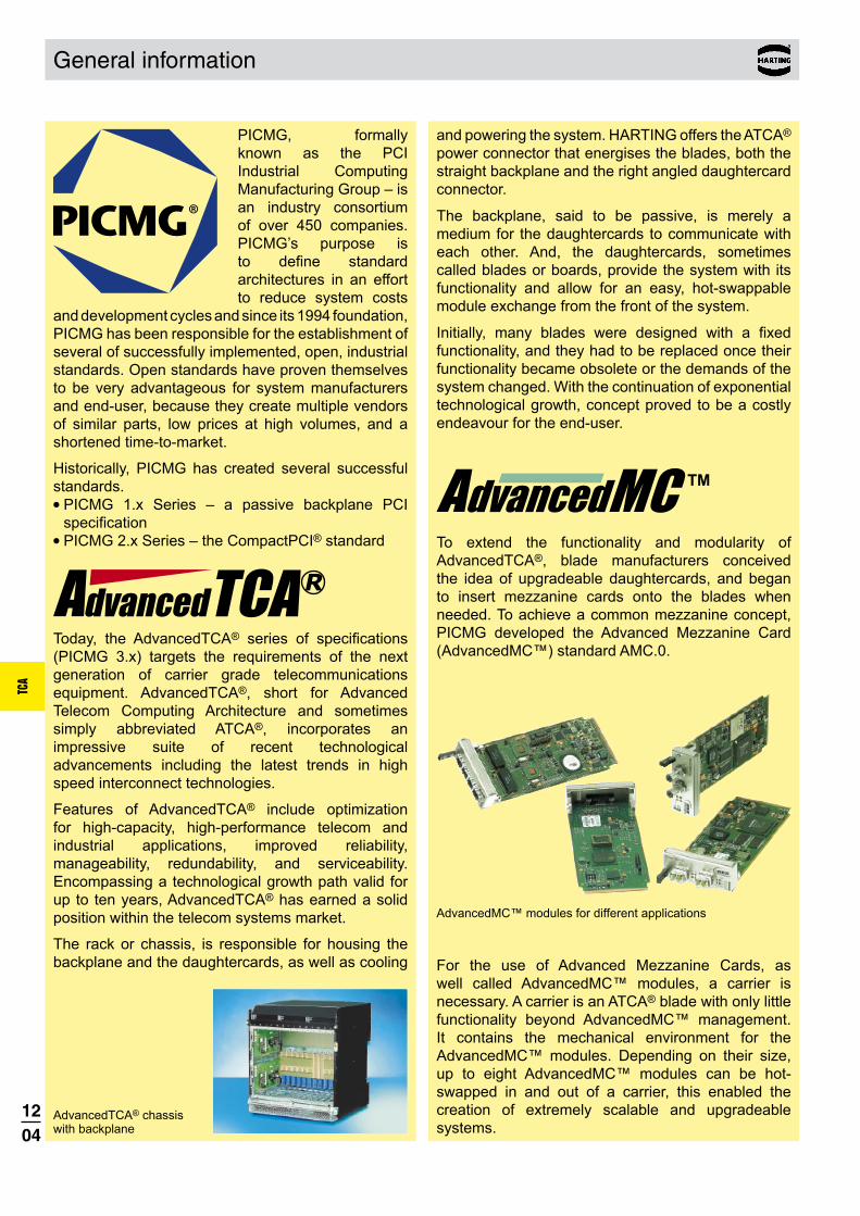
PICMG, formally known as the PCI Industrial Computing Manufacturing Group – is an industry consortium of over 450 companies. PICMG’s purpose is to define standard architectures in an effort to reduce system costs
and development cycles and since its 1994 foundation, PICMG has been responsible for the establishment of several of successfully implemented, open, industrial standards. Open standards have proven themselves to be very advantageous for system manufacturers and end-user, because they create multiple vendors of similar parts, low prices at high volumes, and a shortened time-to-market.
Historically, PICMG has created several successful standards. l PICMG 1.x Series – a passive backplane PCI
specificationl PICMG 2.x Series – the CompactPCI® standard
Today, the AdvancedTCA® series of specifications (PICMG 3.x) targets the requirements of the next generation of carrier grade telecommunications equipment. AdvancedTCA®, short for Advanced Telecom Computing Architecture and sometimes simply abbreviated ATCA®, incorporates an impressive suite of recent technological advancements including the latest trends in high speed interconnect technologies.
Features of AdvancedTCA® include optimization for high-capacity, high-performance telecom and industrial applications, improved reliability, manageability, redundability, and serviceability. Encompassing a technological growth path valid for up to ten years, AdvancedTCA® has earned a solid position within the telecom systems market.
The rack or chassis, is responsible for housing the backplane and the daughtercards, as well as cooling
and powering the system. HARTING offers the ATCA® power connector that energises the blades, both the straight backplane and the right angled daughtercard connector.
The backplane, said to be passive, is merely a medium for the daughtercards to communicate with each other. And, the daughtercards, sometimes called blades or boards, provide the system with its functionality and allow for an easy, hot-swappable module exchange from the front of the system.
Initially, many blades were designed with a fixed functionality, and they had to be replaced once their functionality became obsolete or the demands of the system changed. With the continuation of exponential technological growth, concept proved to be a costly endeavour for the end-user.
To extend the functionality and modularity of AdvancedTCA®, blade manufacturers conceived the idea of upgradeable daughtercards, and began to insert mezzanine cards onto the blades when needed. To achieve a common mezzanine concept, PICMG developed the Advanced Mezzanine Card (AdvancedMC™) standard AMC.0.
AdvancedMC™ modules for different applications
For the use of Advanced Mezzanine Cards, as well called AdvancedMC™ modules, a carrier is necessary. A carrier is an ATCA® blade with only little functionality beyond AdvancedMC™ management. It contains the mechanical environment for the AdvancedMC™ modules. Depending on their size, up to eight AdvancedMC™ modules can be hot-swapped in and out of a carrier, this enabled the creation of extremely scalable and upgradeable systems.
AdvancedTCA® chassis with backplane
1205
TCA
General information
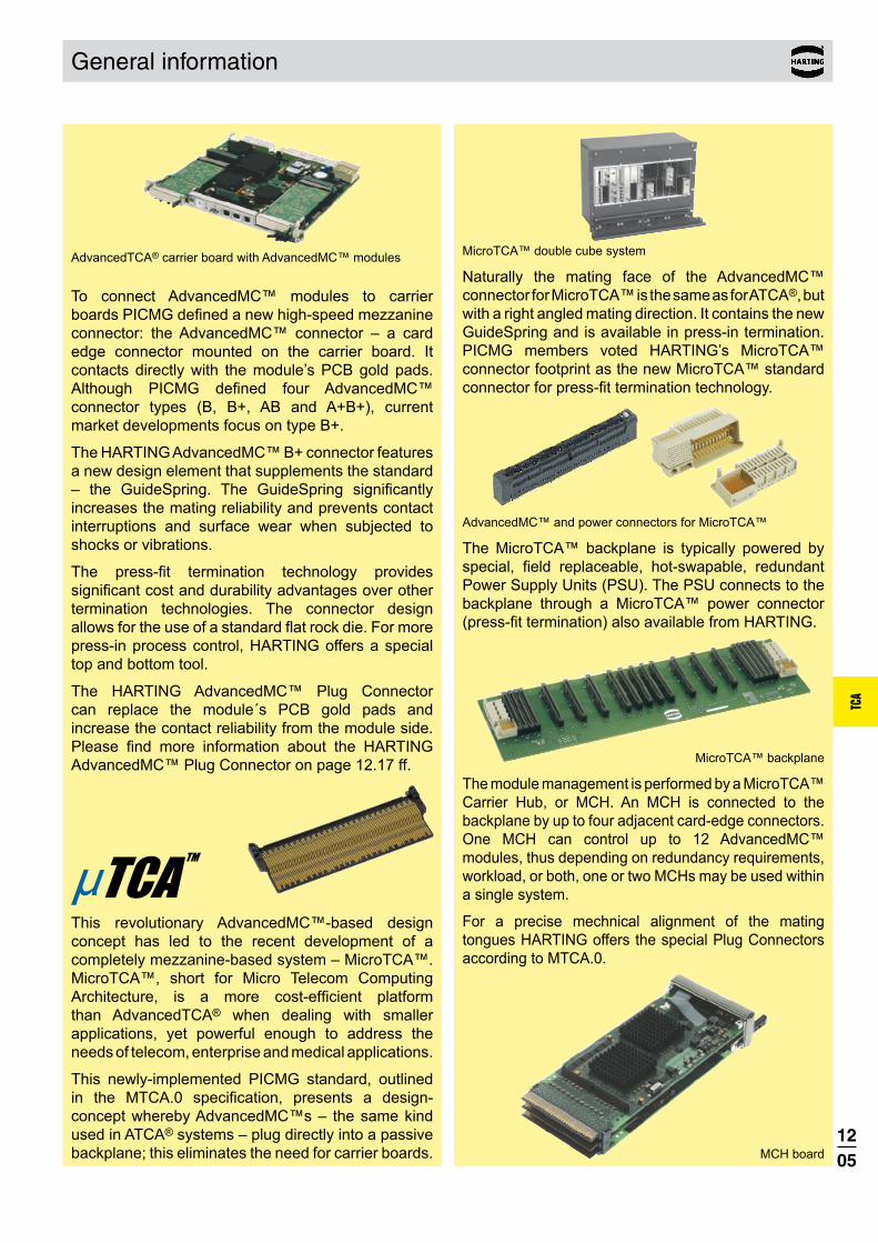
AdvancedTCA® carrier board with AdvancedMC™ modules
To connect AdvancedMC™ modules to carrier boards PICMG defined a new high-speed mezzanine connector: the AdvancedMC™ connector – a card edge connector mounted on the carrier board. It contacts directly with the module’s PCB gold pads. Although PICMG defined four AdvancedMC™ connector types (B, B+, AB and A+B+), current market developments focus on type B+.
The HARTING AdvancedMC™ B+ connector features a new design element that supplements the standard – the GuideSpring. The GuideSpring significantly increases the mating reliability and prevents contact interruptions and surface wear when subjected to shocks or vibrations.
The press-fit termination technology provides significant cost and durability advantages over other termination technologies. The connector design allows for the use of a standard flat rock die. For more press-in process control, HARTING offers a special top and bottom tool.
The HARTING AdvancedMC™ Plug Connector can replace the module´s PCB gold pads and increase the contact reliability from the module side. Please find more information about the HARTING AdvancedMC™ Plug Connector on page 12.17 ff.
This revolutionary AdvancedMC™-based design concept has led to the recent development of a completely mezzanine-based system – MicroTCA™. MicroTCA™, short for Micro Telecom Computing Architecture, is a more cost-efficient platform than AdvancedTCA® when dealing with smaller applications, yet powerful enough to address the needs of telecom, enterprise and medical applications.
This newly-implemented PICMG standard, outlined in the MTCA.0 specification, presents a design-concept whereby AdvancedMC™s – the same kind used in ATCA® systems – plug directly into a passive backplane; this eliminates the need for carrier boards.
MicroTCA™ double cube system
Naturally the mating face of the AdvancedMC™ connector for MicroTCA™ is the same as for ATCA®, but with a right angled mating direction. It contains the new GuideSpring and is available in press-in termination. PICMG members voted HARTING’s MicroTCA™ connector footprint as the new MicroTCA™ standard connector for press-fit termination technology.
AdvancedMC™ and power connectors for MicroTCA™
The MicroTCA™ backplane is typically powered by special, field replaceable, hot-swapable, redundant Power Supply Units (PSU). The PSU connects to the backplane through a MicroTCA™ power connector (press-fit termination) also available from HARTING.
MicroTCA™ backplane
The module management is performed by a MicroTCA™ Carrier Hub, or MCH. An MCH is connected to the backplane by up to four adjacent card-edge connectors. One MCH can control up to 12 AdvancedMC™ modules, thus depending on redundancy requirements, workload, or both, one or two MCHs may be used within a single system.
For a precise mechnical alignment of the mating tongues HARTING offers the special Plug Connectors according to MTCA.0.
MCH board

1206
TCA
con:card+
PdNi contact coatingIn order better to meet the high requirements placed on the connectors, a palladium-nickel surface (PdNi) with additional gold flash is used.As a result, wear resistance is increased by roughly 30 %. Even when applied very thinly, PdNi surfaces offer a quality and corrosion-resistant coating that meets the high requirements placed on the connection far better than pure gold.
Special contact designUnlike conventional mating systems with male and female connectors, the AdvancedMC™ has only one, not two, contact tongues per contact. In order to ensure a permanently reliable contact, this single contact tongue must press against the gold pad with sufficient force throughout the entire lifetime. In addition, the thickness of the AdvancedMC™ modules may fluctuate by ±10 %. To meet this challenge, HARTING utilizes a special contact design with very low relaxation for the con:card+ connector.
What is con:card+?con:card+ is a quality seal for AdvancedMC™ connectors that helps to deliver a significant increase in the reliability of MicroTCATM and AdvancedTCA® systems. In order to reach the target availability of 99.999 %, all system components must be carefully coordinated, and they must function reliably. The selection of suitable connectors is an essential, decisive factor here, as today it is virtually impossible for series production to meet the strict tolerances for the AdvancedMCTM modules as defined in the respective specifications. The so-called GuideSpring is ideally suited for compensating here, and represents just one of a total of five key advantages of the con:card+ philosophy. All the advantages are introduced in the following. Please find further information also on the internet at www.concardplus.com.
1207
TCA
GuideSpringPCB manufacturers are not capable of meeting the AdvancedMC™ modules’ tight tolerances with certainty in the series process today. Just a single card with tolerances slightly larger than allowed by the specifications can lead to a system breakdown.The con:card+ GuideSpring offsets these tolerance deviations by constantly pressing the module against the opposite wall. As this is displaced somewhat towards the middle, the slot is optimally designed for the AdvancedMC™ module, and the mating reliability increases tremendously. In addition, the GuideSpring secures the module position in the case of shocks and vibrations. This prevents loss of contact and surface wear.
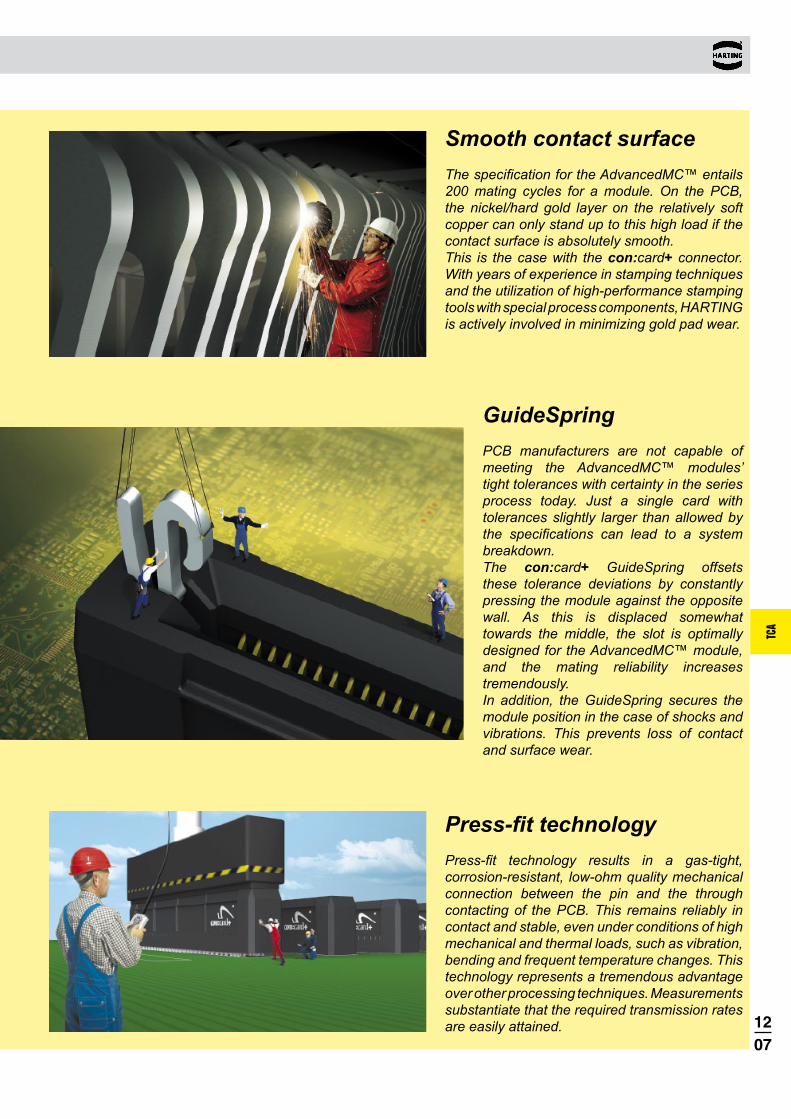
Smooth contact surfaceThe specification for the AdvancedMC™ entails 200 mating cycles for a module. On the PCB, the nickel/hard gold layer on the relatively soft copper can only stand up to this high load if the contact surface is absolutely smooth. This is the case with the con:card+ connector. With years of experience in stamping techniques and the utilization of high-performance stamping tools with special process components, HARTING is actively involved in minimizing gold pad wear.
Press-fit technologyPress-fit technology results in a gas-tight, corrosion-resistant, low-ohm quality mechanical connection between the pin and the through contacting of the PCB. This remains reliably in contact and stable, even under conditions of high mechanical and thermal loads, such as vibration, bending and frequent temperature changes. This technology represents a tremendous advantage over other processing techniques. Measurements substantiate that the required transmission rates are easily attained.

1208
TCA
Design according PICMG AMC.0 (RoHS compliance)
Materials Moulded parts Liquid Crystal Polymer
(LCP), UL 94-V0Contacts Copper AlloyContact surface Pd/Ni with Au flash
AdvancedMC™ connectors for AdvancedTCA®
Number of contacts 170Contact spacing 0.75 mmClearance and creepage distance between contacts 0.1 mm min.
Nominal differential impedance 100 W±10 %
Max. crosstalk @ 25 ps risetime Bottom routeAdjacent 0.55 %Basic-to-extended (diagonal) 0.68 %Basic-to-extended (opposite) 0.39 %Multiline (five multi-aggressor differential pairs) 2.74 % max.
extended side
basic side
ground
2.25 0.75
1.5
1.5
1.5
1.5
Crosstalk_TCA.indd 1 30.01.2008 07:32:16
PCB library on request (PADS/Dx-Designer)
SPICE models and S-Parameter on request
Differential propagation delay Basic side: 125 ps Extended side: 145 psDifferential skew Between basic and extended side: 20 ps Within basic and extended side: ±2 ps
Working current of ~ 2.2 A @ 70 °C power contacts max. 30 °C temp. rise as defined (PICMG requirement min. 1.52 A) in AMC.0 spec.
Test voltage 80 Vr.m.s.
Working voltage typically 3.3 V; 5.0 V; 12.0 V
Initial contact resistance ground contacts 60 mW max. signal, power, general purpose contacts 90 mW max.Initial insulation resistance 100 MW min.
Temperature range -55 °C … +105 °CDurability as per AMC.0 specification 200 mating cycles
Termination technique Press-in terminationMating force 100 N max., typically 65 - 90 N
( depending on AdvancedMC™)Withdrawal force 65 N max., typically 30 - 45 N
( depending on AdvancedMC™)
Packaging Cardboard box (other packaging on request)
Technical characteristics
Recommended plated through hole specification
A Drill hole-Ø 0.64±0.01 mm
B Cu 25 - 35 µm
Tin plated PCB (HAL)
C Sn 5 - 15 µm
D Hole-Ø 0.53 - 0.60 mm
Au / Ni plated PCB
C Ni 3 - 7 µm
Au 0.05 - 0.12 µm
D Hole-Ø 0.55 - 0.60 mm
Chemical tin plated PCB
C Sn 0.8 - 1.5 µm
D Hole-Ø 0.56 - 0.60 mm
OSP copper plated PCB
C --- ---
D Hole-Ø 0.56 - 0.60 mm
E Pad size min. 0.95 mm
The press-in zone of the AdvancedMC™ connector is tested according to Telcordia/Bellcore GR 1217CORE Part7. It is approved to be used with a plated through hole according IEC 60 352-5 with a diameter of 0.55±0.05 mm (drilled hole 0.64±0.01 mm).Based on our experiences regarding the production process of the PCB manufacturer we recommend a plated through hole configuration like shown in the above spreadsheet. To achieve the recommended plated through hole diameter, it is important to specify especially the drilled hole diameter of 0.64±0.01 mm to your PCB supplier.For drillings use e.g. drill bit # 72 (0.025" ≈ 0.64 mm).

1209
TCA
Contact length [mm] No. of terminationIdentification contacts side Part number
170 2.0 16 04 170 5104 000AdvancedMC™ connector for ATCA®, type B+
with peg and with GuideSpring
With peg With peg
Dimensions [mm]
170 2.0 16 04 170 5106 000AdvancedMC™ connector for ATCA®, type B+
without peg and with GuideSpring
Without peg Without peg
all holeskeep out area for press in bottom tool
row for ground
Board drillings (view magnified)
AdvancedMC™ connectors for AdvancedTCA®
Card edge connectors, angled
1) fixing-hole optional
2) non-metallized drillings
3) recommended plated through hole specification see page 12.08

1210
TCA
Design according PICMG 3.0 R2.0
Power connectors for AdvancedTCA®
Total number of contacts 30, max. 34
Power contacts 8Signal contacts 22, max. 26
Clearance and creepage distance between contacts
Within group 5–16 0.7 mm min. Within group 17–24 2.5 mm min. 25 to 26 5.5 mm min. Within group 27–34 1.4 mm min. 13–16 to 17–20 3.0 mm min. 21–24 to 25–26 4.0 mm min. 25–26 to 27–29 2.0 mm min.
Sequential contact engagement1st 25, 26, 28, 29, 30, 31 2nd 33 3rd 5–24, 34 4th 27, 32
Working currentPower contacts 16 ASignal contacts 1 A
Test voltageContacts 1–16 1000 Vr.m.s.
Contacts 17–34 2000 Vr.m.s.
Initial contact resistancePower contacts £ 2.2 mW Signal contacts £ 8.5 mW
Insulation resistance ³ 1010 W
Temperature range -55 °C … +125 °CDurability 250 mating cycles Termination technique Press-in terminationMating force 67 N max.Withdrawal force 67 N max.
Materials Moulded parts PBT, glass-fibre filled,
UL 94-V0Contacts Copper AlloyContact surface Selectively gold plated
Packaging Tray packaging (other packaging on request)
Technical characteristics
Recommended plated through hole specification
Signal contacts Power contacts
A Drill hole-Ø 1.15±0.025 mm 1.75±0.025 mm
B Cu 25 - 35 µm 25 - 35 µmTin plated PCB
(HAL)C Sn 5 - 15 µm 5 - 15 µmD Hole-Ø 1.00 – 1.10 mm 1.60 – 1.70 mm
Au / Ni plated PCB
C Ni 3 - 7 µm 3 – 7 µmAu 0.05 - 0.12 µm 0.05 - 0.12 µm
D Hole-Ø 1.00 – 1.10 mm 1.60 – 1.70 mmChemical tin plated PCB
C Sn 0.8 - 1.5 µm 0.8 - 1.5 µmD Hole-Ø 1.00 – 1.10 mm 1.60 – 1.70 mm
Silver plated PCB
C Ag 0.1 - 0.3 µm 0.1 - 0.3 µmD Hole-Ø 1.00 – 1.10 mm 1.60 – 1.70 mm
OSP copper plated PCB
C --- --- ---D Hole-Ø 1.00 – 1.10 mm 1.60 – 1.70 mmE Pad size min. 1.4 mm min. 2.0 mm
The press-in zone of the AdvancedTCA® power con-nector is tested according to Telcordia/Bellcore GR 1217CORE Part7. It is approved to be used with a plated through hole according IEC 60 352-5 with a diameter of 1.00 + 0.09
– 0.06 mm for signal contacts and 1.60 + 0.09– 0.06 mm
for power contacts (drilled hole 1.15±0.025 mm resp. 1.75±0.025 mm).Based on our experiences regarding the production process of the PCB manufacturer we recommend a plated through hole configuration like shown in the above spreadsheet. To achieve the recommended plated through hole diameter, it is important to specify especially the drilled hole diameter of 1.15±0.025 mm resp. 1.75±0.025 mm to your PCB supplier.
Derating for ATCA® power contacts Contact loading acc. PICMG 3.0
À Derating
Á Derating @ Imax. x 0.8 (acc. IEC 60 512-5-2) Ambient temperature [° C]
Cur
rent
[A]

1211
TCA
Power connectors for AdvancedTCA®
Contact length [mm] No. of terminationIdentification contacts side Part number
30 4.1 16 32 030 1101 000 34 4.1 16 32 034 1101 000
Power connector for AdvancedTCA®, male
Dimensions [mm]
30 5.3 16 31 030 1201 000 34 5.3 16 31 034 1201 000
Power connector for AdvancedTCA®, female
Board drillings
1) + 2) recommended plated through hole specification see page 12.10
Male connector with 30 contacts Female connector with 30 contacts
Signal contacts position
Dimension A
5–24 6.127, 32 3.8
Power contacts position
Dimension B
25–26 14.328–31 14.3
33 11.334 8.8
position
view X
position
view X
position
1212
TCA
AdvancedMC™ connectors for MicroTCA™
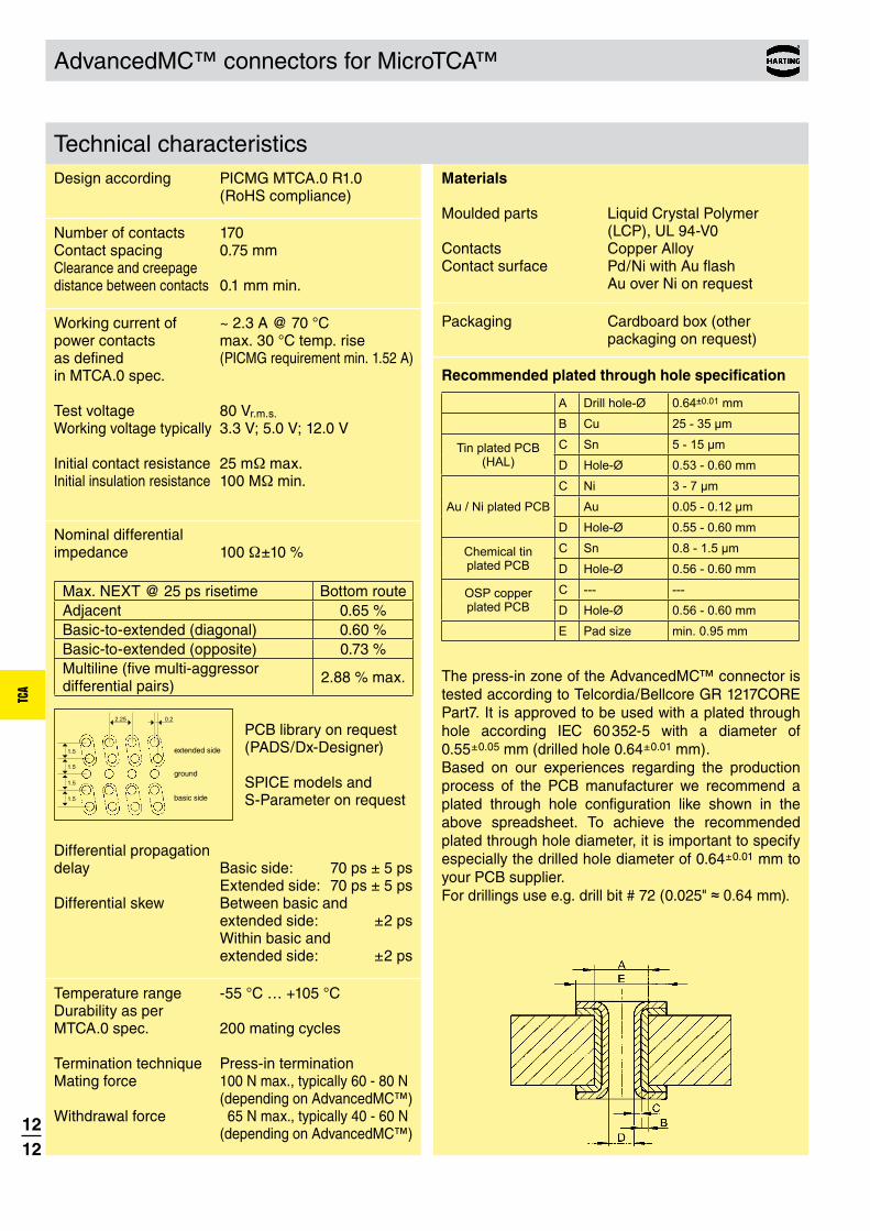
Technical characteristicsDesign according PICMG MTCA.0 R1.0 (RoHS compliance)
Materials Moulded parts Liquid Crystal Polymer
(LCP), UL 94-V0Contacts Copper AlloyContact surface Pd/Ni with Au flash
Au over Ni on request
Number of contacts 170Contact spacing 0.75 mmClearance and creepage distance between contacts 0.1 mm min.
Nominal differential impedance 100 W±10 %
Max. NEXT @ 25 ps risetime Bottom routeAdjacent 0.65 %Basic-to-extended (diagonal) 0.60 %Basic-to-extended (opposite) 0.73 %Multiline (five multi-aggressor differential pairs) 2.88 % max.
extended side
ground
basic side
2.25 0.2
1.5
1.5
1.5
1.5
Crosstalk_MicroTCA.indd 1 04.02.2008 13:23:08
PCB library on request (PADS/Dx-Designer)
SPICE models and S-Parameter on request
Differential propagation delay Basic side: 70 ps ± 5 ps Extended side: 70 ps ± 5 psDifferential skew Between basic and extended side: ±2 ps Within basic and extended side: ±2 ps
Working current of ~ 2.3 A @ 70 °C power contacts max. 30 °C temp. rise as defined (PICMG requirement min. 1.52 A) in MTCA.0 spec.
Test voltage 80 Vr.m.s.
Working voltage typically 3.3 V; 5.0 V; 12.0 V
Initial contact resistance 25 mW max.Initial insulation resistance 100 MW min.
Temperature range -55 °C … +105 °CDurability as per MTCA.0 spec. 200 mating cycles Termination technique Press-in terminationMating force 100 N max., typically 60 - 80 N
( depending on AdvancedMC™)Withdrawal force 65 N max., typically 40 - 60 N
( depending on AdvancedMC™)
Packaging Cardboard box (other packaging on request)
Recommended plated through hole specification
A Drill hole-Ø 0.64±0.01 mm
B Cu 25 - 35 µm
Tin plated PCB (HAL)
C Sn 5 - 15 µm
D Hole-Ø 0.53 - 0.60 mm
Au / Ni plated PCB
C Ni 3 - 7 µm
Au 0.05 - 0.12 µm
D Hole-Ø 0.55 - 0.60 mm
Chemical tin plated PCB
C Sn 0.8 - 1.5 µm
D Hole-Ø 0.56 - 0.60 mm
OSP copper plated PCB
C --- ---
D Hole-Ø 0.56 - 0.60 mm
E Pad size min. 0.95 mm
The press-in zone of the AdvancedMC™ connector is tested according to Telcordia/Bellcore GR 1217CORE Part7. It is approved to be used with a plated through hole according IEC 60 352-5 with a diameter of 0.55±0.05 mm (drilled hole 0.64±0.01 mm).Based on our experiences regarding the production process of the PCB manufacturer we recommend a plated through hole configuration like shown in the above spreadsheet. To achieve the recommended plated through hole diameter, it is important to specify especially the drilled hole diameter of 0.64±0.01 mm to your PCB supplier.For drillings use e.g. drill bit # 72 (0.025" ≈ 0.64 mm).

1213
TCA
I
IIIII
Guide Spring
AdvancedMC™ connectors for MicroTCA™
Contact length [mm] No. of terminationIdentification contacts side Part number
Card edge connectors, straight
Dimensions [mm]
Board drillings (view magnified)
all holes
housing contour
row for groundLc of card slot
with GuideSpring I 170 2.1 16 11 170 5202 000
with GuideSpring and protection shield II 170 2.1 16 11 170 5205 000
with GuideSpring and alignment peg III 170 2.1 16 11 170 5206 000
with GuideSpring, protection shield and alignment peg 170 2.1 16 11 170 5207 000
AdvancedMC™ connectors for MicroTCA™
with alignment peg without alignment peg
alignment peg
without alignment
peg
protection shield
1) recommended plated through hole specification see page 12.12
2) non-metallized drillings optional: for part numbers 16 11 170 5202 000 and 16 11 170 5205 000 mandatory: for part numbers 16 11 170 5206 000 and 16 11 170 5207 000
3) for optional fixing: use self-tapping screws for plastic, 2.2 x length (length = PCB thickness + min. 6.5 mm to max. 10 mm) e.g. HARTING part number 09 06 001 9974 Screwing torque references: PCB + 6.5 mm: 20 cNm PCB + 10 mm: 40 cNm

1214
TCA
Power output connectors for MicroTCA™
Technical characteristicsDesign according PICMG MTCA.0 R1.0 (RoHS compliance)
Temperature range -55 °C … +105 °CDurability 200 mating cycles Termination technique Press-in terminationMating force 145 N max.Withdrawal force 110 N max.
Working currentPower contacts 9.3 A @ 80 % derating
acc. IEC 60 512 and 70 °C ambient temperature and 30 °C temperature rise
Signal contacts 1 A @ 80 % derating acc. IEC 60 512 and 70 °C ambient temperature
Initial contact resistancePower contacts £ 5 mWSignal contacts £ 25 mW
Initial insulation resistance ³ 100 MW min.
Total number of contacts 96
Power contacts 24Signal contacts 72
Sequential contact engagement
1st Power 4–112nd Power 1–3, power 12–243rd Signal A2–H94th Signal A1
Materials Moulded parts PBT, glass-fibre filled,
UL 94-V0Contacts Copper AlloyContact surface
Power contacts: selectively gold platedSignal contacts: selectively
PD/Ni plated
Packaging Tray packaging (other packaging on request)
Recommended plated through hole specification
A Drill hole-Ø 0.7±0.02 mm
B Cu 25 - 35 µm
Tin plated PCB (HAL)
C Sn 5 - 15 µm
D Hole-Ø 0.60 - 0.65 mm
Au / Ni plated PCB
C Ni 3 - 7 µm
Au 0.05 - 0.12 µm
D Hole-Ø 0.60 - 0.65 mm
Chemical tin plated PCB
C Sn 0.8 - 1.5 µm
D Hole-Ø 0.60 - 0.65 mm
Silver plated PCBC Ag 0.1 - 0.3 µm
D Hole-Ø 0.60 - 0.65 mm
OSP copper plated PCB
C --- ---
D Hole-Ø 0.60 - 0.65 mm
E Pad size min. 1.0 mm
The press-in zone of the MicroTCA™ power con-nector is tested according to Telcordia/Bellcore GR 1217CORE Part7. It is approved to be used with a plated through hole according IEC 60352-5 with a diameter of 0.60+0.05 mm (drilled hole 0.70±0.02 mm).Based on our experiences regarding the production process of the PCB manufacturer we recommend a plated through hole configuration like shown in the above spreadsheet. To achieve the recommended plated through hole diameter, it is important to specify especially the drilled hole diameter of 0.70±0.02 mm to your PCB supplier.Derating for MicroTCA™ power contacts
Contact loading acc. MTCA.0
À Derating
Á Derating @ Imax. x 0.8 (acc. IEC 60 512-5-2) Ambient temperature [° C]
Cur
rent
[A]

1215
TCA
Contact length [mm] No. of terminationIdentification contacts side Part number
module version 96 2.8 16 34 096 1101 000
backplane version 96 3.7 16 33 096 1201 000
Power output connectors for MicroTCA™
Dimensions [mm]
Board drillings
1) recommended plated through hole specification see page 12.14
Module version Backplane version
all holesposition
all holes
all holesposition
positionposition
all holes
row
row
row
row
view X
Power output connectors for MicroTCA™
1216
TCA
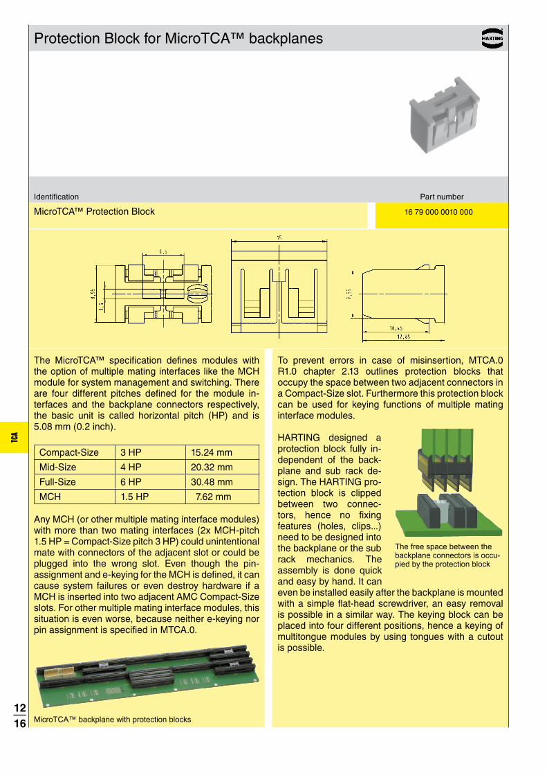
Protection Block for MicroTCA™ backplanes
The MicroTCA™ specification defines modules with the option of multiple mating interfaces like the MCH module for system management and switching. There are four different pitches defined for the module in-terfaces and the backplane connectors respectively, the basic unit is called horizontal pitch (HP) and is 5.08 mm (0.2 inch).
Compact-Size 3 HP 15.24 mm
Mid-Size 4 HP 20.32 mm
Full-Size 6 HP 30.48 mm
MCH 1.5 HP 7.62 mm
Any MCH (or other multiple mating interface modules) with more than two mating interfaces (2x MCH-pitch 1.5 HP = Compact-Size pitch 3 HP) could unintentional mate with connectors of the adjacent slot or could be plugged into the wrong slot. Even though the pin- assignment and e-keying for the MCH is defined, it can cause system failures or even destroy hardware if a MCH is inserted into two adjacent AMC Compact-Size slots. For other multiple mating interface modules, this situation is even worse, because neither e-keying nor pin assignment is specified in MTCA.0.
Identification Part number
MicroTCA™ Protection Block 16 79 000 0010 000
To prevent errors in case of misinsertion, MTCA.0 R1.0 chapter 2.13 outlines protection blocks that occupy the space between two adjacent connectors in a Compact-Size slot. Furthermore this protection block can be used for keying functions of multiple mating interface modules.
HARTING designed a protection block fully in-dependent of the back-plane and sub rack de-sign. The HARTING pro-tection block is clipped between two connec-tors, hence no fixing features (holes, clips...) need to be designed into the backplane or the sub rack mechanics. The assembly is done quick and easy by hand. It can even be installed easily after the backplane is mounted with a simple flat-head screwdriver, an easy removal is possible in a similar way. The keying block can be placed into four different positions, hence a keying of multitongue modules by using tongues with a cutout is possible.
MicroTCA™ backplane with protection blocks
The free space between the backplane connectors is occu-pied by the protection block

1217
TCA
The PICMG specification AMC.0 defined a card edge with gold pads as the mating interface for the
AdvancedMC™ module. As already explained in the chapter “con:card+”, it is very difficult for a PCB manufacturer to produce the tight tolerances required for the AdvancedMC™ module card edge in a consistent process. Furthermore, the quality of the gold pads is only specified in general terms.
Replacing the PCB gold pads with a connector eliminates certain drawbacks of the card edge connection. The HARTING Plug Connector offers the following advantages:
• Controlled quality of both mating sides
• Small dimensional tolerances
• Defined hard gold surface
• Reduced mating forces
• Allows use of thicker PCBs
• Standard reflow solder process
• Cost savings are possible
Controlled quality of both mating sidesThe major advantage is that a solid contact with a band plated surface mates with the backplane connector. The connection is no longer made directly from the card edge to the backplane connector but instead indirectly via a module connector approved from one source. The AdvancedMC™ module with a Plug Connector is still within the dimensional range of the PICMG AMC.0 specification and is fully mating compatible with AdvancedMC™ card edge connectors. Consequently the Plug Connector can be used in both MicroTCA™ and ATCA® environments.
Small dimensional tolerancesThe injection moulding process is much more precise than the PCB production process. While the AMC.0 specification defines a PCB width tolerance of 0.1 mm,
the moulding process has a dimensional tolerance less than 0.03 mm. The lead-in chamfer is milled for the PCB but is realized in the connector as a smooth moulded plastic chamfer. Compared with the rough surface of a PCB chamfer with exposed glass fibre, the smooth Plug chamfer avoids abrasion of the backplane connector contact surface.
Defined hard gold surfaceThe AMC.0 specification defines hard gold to be on the PCB pads. However a common and unique definition of hard gold does not exist today. Additionally, the interruptions of the gold pads (which are necessary for the hot-swap ability) require a selective hard gold process. This is a complex process which is relatively expensive, so commonly just chemical gold with insufficient surface thickness is used. As a result, there are significant differences in the durability of the gold and the surface structure on the modules which are currently available.The contacts of the HARTING AdvancedMC™ Plug Connector are plated all-around and are manufactured in a defined band plating process with controlled quality. There are different performance levels possible as the noble finish thickness can be adapted easily to meet customer demands.
Reduced mating forcesFor the module card edge, the prepads of lagging contacts are required by the Telcordia/Bellcore specification to avoid stress of the connector contact when sliding on the FR4 base material. The Plug Connector does not need prepads. The four mating steps are realized with true lagging contacts. The sophisticated design of the insulator reduces the mating forces of the module significantly.
Allows use of thicker PCBsBy using a HARTING AdvancedMC™ Plug Connector, the mating interface of the module is defined by the connector instead of the PCB. This fact leads to clear advantages and provides a wider scope for the module development. The restriction of the PCB thickness of 1.6 mm +/-10% is no longer a limiting factor. A PCB
General information about Plug Connectors

1218
TCA
General information about Plug Connectors
thickness of e.g. 2 mm can be used as this fits in the mechanical environment.
Standard reflow solder processFor backplanes press-fit termination is the first choice, however solder termination offers advantages for module cards. The Plug Connector is mounted to the
PCB through “pin-in-hole-reflow” solder technology (PIHR). It can be soldered in the same production process as the other semi finished components on the AdvancedMC™ module. Another advantage
of this mechanically stable technology is, that the connector can be replaced. This can avoid the cost of scrapping a module if the mating interface is damaged during handling.
Cost savings are possibleBy offering so many different advantages during the manufacturing process, the use of HARTING Plug Connectors also contributes to keeping costs down. Selective plating increases the cost of producing gold pads. Tight tolerance specifications also cause a large number of rejects. The beveled PCB edge is another
The HARTING Plug Connector is available in two versions. The difference is the mounting direction, i. e. the side of the AdvancedMC™ module PCB on which the Plug Connector is assembled.
Basic sideThe so called basic side refers to the component side 1 as defined in the AMC.0 specification (pins 1 to 85). The main components are mounted on the basic side (sometimes also called top side).During the manufacturing process, a Plug Connector that is mounted from the basic side can be soldered in the same assembly step as the other large components.
Extended sideThe so called extended side refers to the component side 2 as defined in the AMC.0 specification (pins 86 to 170).A Plug Connector mounted on the extended side is “hanging” at the bottom side of the AdvancedMC™ module.
critical area, because damage can occur to the contact pads.
A simple board layout with through-holes is sufficient for the HARTING Plug, and these boards can be
produced inexpensively and with excellent quality control, thus reducing the number of rejects. Furthermore the cost of a reject can be high if a defective PCB edge is not detected until the board is populated with expensive components. A HARTING Plug on a module can be replaced easily, reducing scrapping costs.
This picture shows an AdvancedMC™ module with a Plug Connector mounted on the extended side.
The footprint of a Plug Connector for the basic side is different than that for the extended side. The connectors are not interchangeable. Due to advantages in the assembly of the connector, the basic side version is preferable.For an MCH stack, only connectors having the same mounting direction can be stacked.
Mounting direction
Extended side(Bottom side)
Basic side(Top side)
1219
TCA
Design according PICMG MicroTCA.0 R1.0 PICMG AMC.0 R2.0 (RoHS compliance)
Materials Moulded parts Liquid Crystal Polymer
(LCP), UL 94-V0
Contacts Copper alloy
Contact surface Au over Ni
Nominal differential impedance 100 Ω ± 10 %
Max. crosstalk @ 25 ps risetime Bottom routeAdjacent 0.5 %Basic-to-extended (diagonal) 0.2 %Basic-to-extended (opposite) 0.7 %Multiline (five multi-aggressor differential pairs)
2.1 % max.
Propagation delay Long contact side: 152 ps / 147 ps Short contact side: 121 ps / 129 ps
Skew within differential pairs Long contact side: 5 ps Short contact side: 8 ps
Working current of ~ 2.4 A @ 70 °C power contacts max. 30 °C temp. rise as defined (PICMG requirement min. 1.52 A) in AMC.0 spec., tested with HARTING MicroTCA™ backplane connector
Test voltage 80 Vr.m.s.
Working voltage typically 3.3 V; 5.0 V; 12.0 V
Initial contact resistance 25 mW max. Initial insulation resistance 100 MW min.
Number of contacts 170
Contact spacing 0.75 mm
Clearance and creepage distance between contacts 0.1 mm min.
Temperature range -55 °C … +105 °C during reflow soldering 220 °C for 2 minutes 270 °C max. short-term
Durability as per AMC.0 specification 200 mating cycles in total
Termination technique Solder termination (Pin in Hole Intrusive Reflow)
Mating force 100 N max., typically 40 - 70 N ( depending on backplane connector)
Withdrawal force 65 N max., typically 30 - 50 N ( depending on backplane connector)
The mating and withdrawal force is highly depending on the mating half connector, but typically only 50 % to 70 % of the mating force of a PCB card edge.
Packaging Tray packaging (other packaging on request)
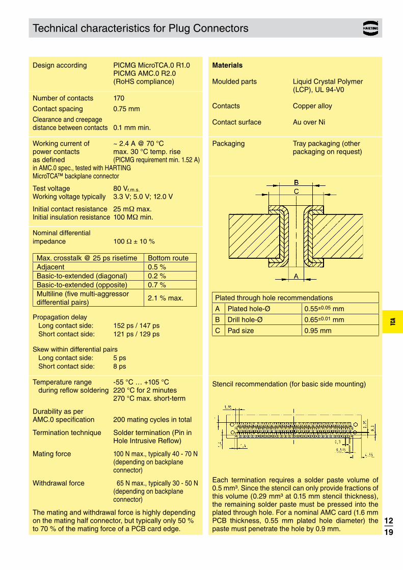
Plated through hole recommendations
A Plated hole-Ø 0.55±0.05 mm
B Drill hole-Ø 0.65±0.01 mm
C Pad size 0.95 mm
Technical characteristics for Plug Connectors
Stencil recommendation (for basic side mounting)
Each termination requires a solder paste volume of 0.5 mm³. Since the stencil can only provide fractions of this volume (0.29 mm³ at 0.15 mm stencil thickness), the remaining solder paste must be pressed into the plated through hole. For a nominal AMC card (1.6 mm PCB thickness, 0.55 mm plated hole diameter) the paste must penetrate the hole by 0.9 mm.

1220
TCA
170 16 23 170 1301 000
Plug Connector for AdvancedMC™ modules
No. ofIdentification contacts Part number
AdvancedMC™ Plug Connectorfor basic side mounting
Dimensions [mm]
Board drillings (view of the basic side / component side 1)
AdvancedMC™ Plug Connector for basic side mounting
For mounting on basic side

1221
TCA
170 16 21 170 1303 000
Plug Connector for AdvancedMC™ modules
No. ofIdentification contacts Part number
AdvancedMC™ Plug Connectorfor extended side mounting replacement of former part number 16 21 170 1301 000
Dimensions [mm]
Board drillings (view of the extended side / component side 2)
AdvancedMC™ Plug Connector for extended side mounting
For mounting on extended side

1222
TCA
General information about MCH Plug Connectors
An important component of a MicroTCA™ system is the “MicroTCA™ Carrier Hub”, abbreviated MCH. The main functions of an MCH module are hardware platform management and the management of the fabric connectivity. Since the MCH module requires many more connections than a standard AdvancedMC™ module, an MCH may have up to 4 mating tongues each with 170 contacts.
The MTCA.0 specification recommends the use of a special Plug Connector to reduce the insertion force of the module and to solve the tolerance stack-up problem between the multiple tongues and the backplane connectors.
The HARTING Plug Connector system consists of three different Plug Connectors. The AdvancedMC™ Plug is required for an MCH module and is always used in the MCH1-slot. Furthermore it can be used for any conventional AdvancedMC™ module to replace the pcb gold pads.
AdvancedMC™ Plug, MCH Plug, Piggyback Plug
If more than one mating tongue is needed, the MCH Plug Connector is mated with the backplane MCH connectors 2 and 3 depending on the MicroTCA™
configuration. Compared to the AdvancedMC™ Plug, the MCH Plug insulator has standoffs ensuring the correct distance for the slot width between two tongues or backplane connectors respectively. The MCH and AdvancedMC™ Plugs have different contact staggering on the basic side, the extended side is equal.
The Piggyback Plug Connector is designed for the MCH4 slot, but the connector itself is soldered on the PCB3. For a MicroTCA™ system with more than 6 AdvancedMC™ modules using the switched fabric fat pipe, an MCH module with 4 mating tongues must be used. In general the switched fabric is located only on the PCB3, so a high-speed connection is needed between the MCH4 slot and the PCB3.
To build a connector stack for two, three or four mating tongues, the HARTING Plug Connectors are mounted like building blocks via pegs and the holes on the adjacent Plugs. For additional mechanical stability, the connector stack is fixed using metal stacking pins. The complete connector stack can be installed easily without any special tooling.
Exploded view of an MCH stack with four tongues including Piggyback Plug
As with the AdvancedMC™ Plug, HARTING offers the Plug Connectors for MCH modules in versions for basic side or extended side mounting. Only connectors with the same mounting direction can be stacked together. The Piggyback Plug is only available as basic side version, therefore for a MCH module with four tongues, the basic side version is preferred.
MCH stacks in basic side version with 2, 3 and 4 tonguesMCH stack in extended side
version

1223
TCA
170 16 23 170 1301 000
170 16 24 170 1301 000
Plug Connectors for MCH modules
No. ofIdentification contacts Part number
Dimensions [mm]
Board drillings (view of the basic side / component side 1)
Dimensions for AdvancedMC™ Plug Connector for basic side mounting see page 12.20.
MCH Plug Connector for basic side mounting
For mounting on basic side
AdvancedMC™ Plug Connector for basic side mounting
MCH Plug Connector for basic side mounting
AdvancedMC™ – MCH Plug stacking-pin for basic side mounting
double length (for two stacked plugs) 11 mm 16 79 000 0017 000 triple length (for three stacked plugs) 18.5 mm 16 79 000 0019 000 quad length (for four stacked plugs) 22.5 mm 16 79 000 0020 000

1224
TCA
170 16 21 170 1303 000
170 16 22 170 1303 000
Plug Connectors for MCH modules
No. ofIdentification contacts Part number
Dimensions [mm]
Board drillings (view of the extended side / component side 2)
Dimensions for AdvancedMC™ Plug Connector for extended side mounting see page 12.21.
MCH Plug Connector for extended side mounting
For mounting on extended side
AdvancedMC™ Plug Connector for extended side mounting replacement of former part number 16 21 170 1301 000
MCH Plug Connector for extended side mounting replacement of former part number 16 22 170 1301 000
AdvancedMC™ – MCH Plug stacking-pin for extended side mounting
double length (for two stacked plugs) 11.5 mm 16 79 000 0006 000 triple length (for three stacked plugs) 19 mm 16 79 000 0007 000 quad length (for four stacked plugs) 26.5 mm 16 79 000 0008 000

1225
TCA
170 16 25 170 1301 000
Plug Connectors for MCH modules – Piggyback connector
No. ofIdentification contacts Part number
MCH Piggyback Plug Connectorapplicable only in basic side mounting configuration
Dimensions [mm]
Board drillings (view of the basic side / component side 1)
MCH Piggyback Plug Connector
Footprint of Piggyback connector
Footprint of MCH connector