Embed Size (px)
DESCRIPTION
Salt and Shale
Citation preview

1
12. VERTICAL-DISPLACEMENT STRUCTURES ASSOCIATED WITH SALT AND OVERPRESSURED SHALE
Figure 1. Vertical structural family. Topics Habitat Mechanics Material properties Displacements Small Extension Style Classical Salt Tectonics: Vertical Evolution Flank traps Crestal traps Restoration and restoration pitfalls Salt Sheets Pseudoextension Roho fault system Stepped counter regional fault system Big Extension Style

2
Habitat Salt deposits are typically formed in the early stages of rifting. Salt and overpressured shale structures are predominately located on passive continental margins (figs. 2-3) with some examples located elsewhere including on the craton.
Figure 2. Passive plate margins.
Figure 3. Major salt deposits of the world (Martinez, 1974).

3
Mechanics Material properties The key factors that cause salt and overpressured shale tectonics to be very different from other structural styles is that both salt and overpressured shale are very deformable, buoyant relative to lithified sediments, and able to flow under the differential stress caused by differential gravitational loading (fig. 4).
a b
c Figure 4. Key mechanical factors influencing deformation of salt and overpressured shale. . a Soft and ductile material deforms easily. b. Buoyant oil rising into more dense syrup (Ramberg, 1981). c. Stress caused by differential load. Displacements The displacements leading to the deformation of salt, overpressured shale, and their cover sequences range from extension to vertical, to compressional. Here we are concerned with primarily with vertical displacements, but certain extensional styles are covered too. Flow of salt or shale toward a round or elliptical region produces vertical movement in the cover, resulting in a dome or diapir. Movement within a diapir is vertical. By definition, a diapir pierces its overburden. Piercement is defined as a high angle contact between the core material and the country rock. An active diapir forms by arching and fracturing the cover sequence (fig. 5). Either a full graben or a half graben above the dome can accommodate the extension.
4
a 1 unit
1
2
3
R
0%2.6%
b 1 unit
1
2
3
R
4.4%1.8%
Figure 5. Alternative models for the deformation in the arch above a hemispherical intrusion. Bedding is approximately constant in thickness on the flanks of the uplift. Layer-parallel requisite extensional strains are shown. a. Full graben. b. Half graben
Stratigraphic units that intersect the flank of a diapir without evidence of uplift (no increase in dip adjacent to the diapir) imply passive growth. In a passive diapir it is inferred that the top of the diapir remained at or close to the depositional interface while sediments were deposited around it. Much of the history of tall diapers appears to be passive growth (fig. 6).
Figure 6. Stratigraphic relationships showing a dome beginning as active/reactive, then becoming passive, then active at the last stage, schematic after Belle Isle dome, Louisiana (O.Neill, 1973, in Yin, 2003).

5
Pseudoextension produces a normal fault by rotation of the hangingwall and lateral displacement of the ductile substrate. Although a major normal fault is produced, there is no net horizontal displacement of the hangingwall. Steep dips in the hangingwall imply material transfer from below the subsiding half graben into an adjacent uplift (fig. 7).
Figure 7. Large rotations associated with lateral movement of shale (Dailly, 1976). A reactive diapir forms as the isostatic response to extension of the cover (fig. 8). The identifying characteristic is subsidence of the cover sequence adjacent to the diapir. Reactive diapirs formed in response to regional extension should be linear, not round. Round active or passive diapirs might be triggered by extension, however (Vendeville and Jackson, 1992). Structures produced by large regional extension involving salt or shale will be treated in this chapter because the structural styles in the overburden are more like vertical salt tectonics than the thin-skinned extension treated in Chapter 11.
Figure 8. Reactive diapir formed in response to horizontal extension (Nilsen et al., 1996).

6
Small Extension Style The continental margin sequence above a salt or overpressured shale layer may glide or spread toward deep water, producing a variety of structures (fig. 9). Commonest are down to basin faults with salt-cored footwall uplifts known as rollers (fig. 10). A primary salt weld represents a horizon where the autochthonous salt is completely gone. The North Choctaw Ridge oil field, formed near the updip limit of salt in the Gulf of Mexico, is an example (fig. 11).
Figure 9. Structures related to slip on autochthonous salt (Rowan et al., 1999).
Figure 10. Salt rollers on autochthonous salt (Rowan, 1999, after Bally, 1981).

7
Figure. 11. North Choctaw Ridge oil field, Alabama, USA (Qi et al, 1998). This field has produced about 5 million barrels of oil.

8
Classical Salt Tectonics: Vertical The Paradox basin of the western U.S. provides an example of the early development of active piercement structures (figs. 12-13). The salt first migrates into anticlines which are then pierced at a few locations along their lengths to form domes. The termination of younger units at the diapir (fig. 13) indicates passive growth. Vertical salt movement is likely to begin where the salt is thickest, such as over the edge of the deep part of a half graben (fig. 13), a correlation seen elsewhere (e.g. Jenyon, 1986; Krzywiec, 2004).
a b Figure 12. Paradox basin, western U.S. a. Sinbad Valley, a salt piercement structure. b. Tectonic map of the salt structures in the basin (Elston and Shoemaker, 1963).
Figure 13. Sequential evolution of salt anticlines of the Paradox Basin (Elston and Shoemaker, 1963).

9
The arching and extension of the cover make the Chinguetti dome an example of an active diapir (fig. 14). The turbidite reservoir unit is not deflected around the dome (fig. 14a), indicating that doming occurred after deposition.
a
b Figure. 14. Chinguetti field, offshore Mauritania, west Africa (Vear, 2005). The reserves are estimated to be 120 million barrels of oil. a. RMS amplitude extraction highlighting the turbidite sandstone reservoir facies. b. Profile along line A-A’, optical stack of 20 traces. Arrows indicate oil-water contacts.
10
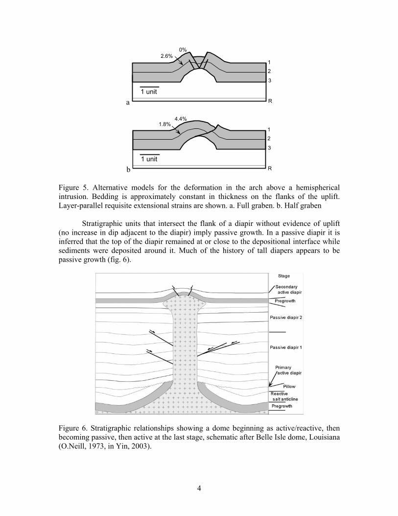
Evolution The structure evolves from a flat-lying bed into a pillow or anticline as salt/shale moves laterally. Stratigraphic thinning occurs over the crest and thickening into the area from which the salt has been evacuated to form the primary rim syncline. When enough material accumulates in the pillow or anticline, the overburden breaks and a diapir grows upward. The pillow/anticline collapses and the sediment fill forms the secondary rim syncline. The timing of dome growth is given by the relative ages of the primary and secondary rim synclines (figs. 15-17).
Figure 15. Sequential evolution of an active salt piercement structure (Sannemann, 1968)
Figure 16. Relative timing of dome growth dated by superposition of primary and secondary rim synclines (Sannemann, 1968).

11
Figure 17. Relative ages of dome growth (Sannemann, 1968). The evolution from pillow to diapir may include erosional unconformities (fig. 18-19).
Figure 18. Seismic line across a North Sea salt dome with erosion in the pillow stage (Jenyon, 1986).

12
Figure 19. Evolution of the salt dome in previous figure (Jenyon, 1986). Progressive salt withdrawal in multiple directions from beneath a primary rim syncline leads to the formation of a turtle structure (fig. 20). The turtle is a depositional syncline that is inverted to form an anticline after the salt has migrated away. The Bryan field is a turtle anticline oil field (fig. 21).
Figure 20. Formation of a turtle structure (Woodbury et al., 1980).

13
a
b Figure. 21. Bryan field turtle structure, Mississippi interior salt basin, USA. Approximately 25 million barrels of oil have been produced from Cretaceous reservoirs. a. Schematic cross section (Oxley and Herlihy, 1972). b. Structure contours on top Sligo reservoir (Davis and Lambert, 1963).

14
Flank Traps Beds close to the salt margin are usually poorly imaged on seismic reflection profiles (fig. 22), but abundant well data and some outcrop data are available to illustrate the structures. Many traps relate to passive growth phases (fig. 23a), but very steep dips suggest episodes of active diapirism (figs. 23b-24). Many stratigraphic traps are found on the flanks of diapers (fig. 25a). The ultimate piercement leaves the salt detached from the source bed (fig. 25b). The stage of evolution attained depends on the amount of salt present (fig. 26). Shale can produce all the same structures (fig. 27).
Figure 22. Piercement diapir, characteristically poorly imaged on seismic (Rowan, 1995).
a b Figure 23. Oil traps on salt piercements (Halbouty, 1967). a. Passive piercement, Cote Blanche dome, Louisiana. 138 million barrels of oil ultimate recovery, 10 bcf gas reserves. b. Active piercement, Nash dome, Texas. 3.3 million barrels oil from 4 separate traps.

15
Figure 24. 2-D seismic line across flank of diapir in Precaspian Basin, Kazakhstan (Rowan et al., 2003).
a b Figure 25. Salt piercement structures (Halbouty, 1967). a. South Liberty dome, Texas. 88 million barrels of oil, 1.2 million barrels condensate and 32 tcf gas from 5 reservoirs. b. Eilte dome,Germany.
Figure 26. Salt geometry related to original salt thickness (Trusheim, 1960).

16
Figure. 27. Regional dip line across northern Port Isabel fold belt trend, western Gulf of Mexico (Camerlo et al., 2005).The Anahuac diapiric shale is shaded. The shale is not overpressured.
Crestal traps
The most obvious salt-dome trap is the dome itself (fig. 28). The structure of a dome being actively pierced usually includes numerous faults (fig. 30) which are difficult to image on seismic (fig. 31) and difficult to correlate between wells.
Figure 28. Dome above a salt diapir, Scoter field, UK North Sea (Hempton et al., 2005). The field is estimated to contain 200 bcf gas.

17
Figure. 29. Reitbrook dome, Germany Schmitz and Flixeder, 1993).
Figure 30. Crestal area of diaper (Rowan et al., 2003).
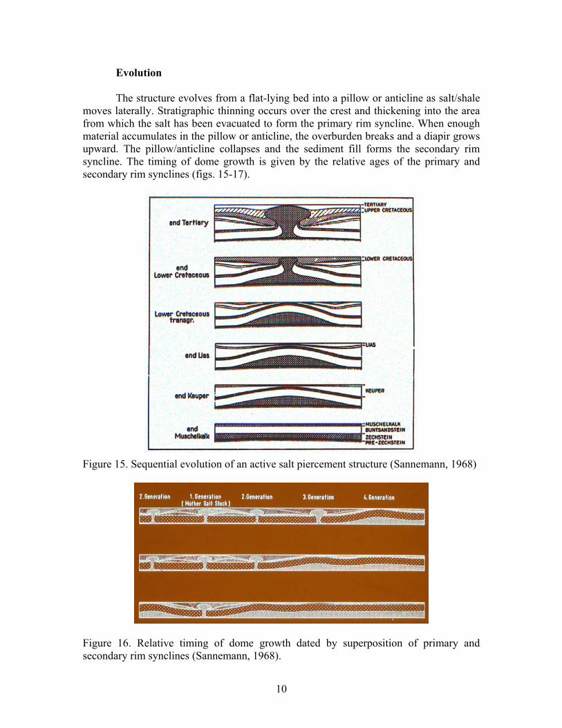
Because of the three-dimensional complexity of the fault pattern over an active dome, it is important to recognize what fault systems are kinematically possible. Based on a review of low-relief domes over piercement diapers, it appears that the the initial fault pattern is either two or three crossing normal faults (figs. 31-32). The faults may either cut the top of salt or detach at that level (figs. 31-32). The styles are controlled by these two factors and the direction of the cross section with respect to the master faults (figs. 33-36).
18
Figure 31. Characteristic features of circular domes (Yin and Groshong, 2007). a. X pattern, West Clara field dome, Mississippi (after Davis and Lambert, 1964). b. Y pattern, Clay Creek dome, Texas (after McDowell, 1951). c. Smooth salt top, Clay Creek dome, Texas (after McDowell, 1951). d. Faulted salt top, Heide salt dome, northern Germany (after Boigk, 1981).

19
c Figure 32. Displacement on X and Y pattern faults (Yin and Groshong, 2003; 2007). a, b. Faults cut top of salt. c. Strained zone required if faults detach on top salt.
Figure 33. Map view of Y-pattern faults (Yin and Groshong, 2007). a. Faults cut top salt. b. Faults detach on top salt.

20
Figure 34. Style as a function of direction where faults cut salt (Yin and Groshong, 2007). a-c. Cross sections parallel to a master fault. d-g. Cross sections perpendicular to a master fault.
Figure 35. Style as a function of direction where faults detach on top salt (Yin and Groshong, 2007). h-j. Cross sections parallel to a master fault. k-m. Cross sections perpendicular to a master fault.
21
a
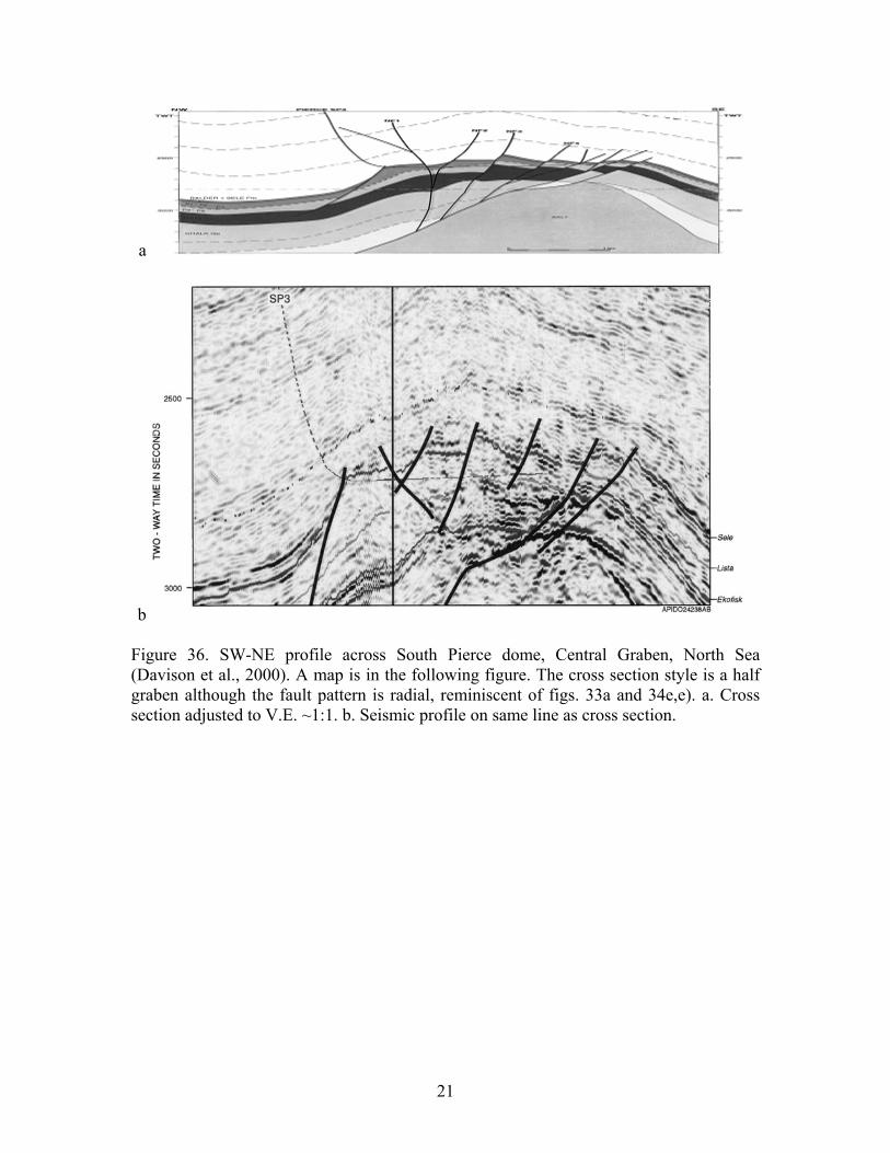
b Figure 36. SW-NE profile across South Pierce dome, Central Graben, North Sea (Davison et al., 2000). A map is in the following figure. The cross section style is a half graben although the fault pattern is radial, reminiscent of figs. 33a and 34e,e). a. Cross section adjusted to V.E. ~1:1. b. Seismic profile on same line as cross section.

22
Figure. 37. Structure contour map on top of Paleocene reservoir, Pierce field, Central Graben, North Sea (Dennis et al., 2005). This field has reserves of 40 million barrels of oil and 202 bcf gas. The oil-water contact is tilted because of lateral pressure gradients in the aquifer.
23
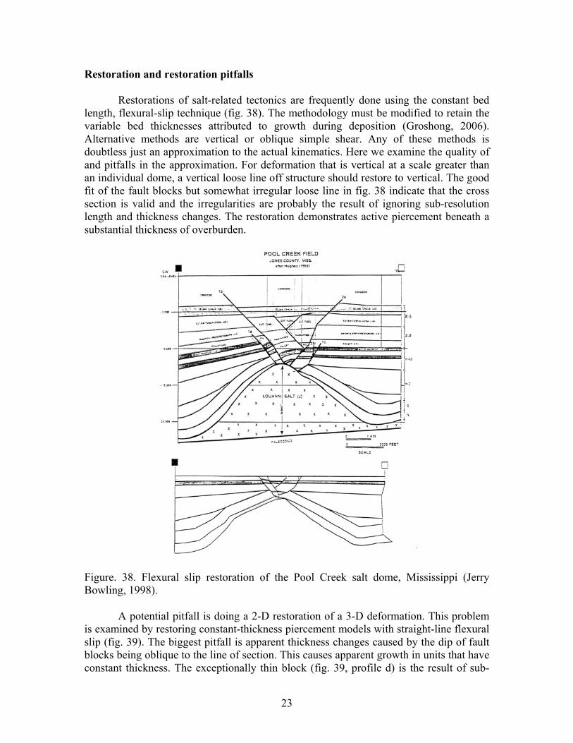
Restoration and restoration pitfalls Restorations of salt-related tectonics are frequently done using the constant bed length, flexural-slip technique (fig. 38). The methodology must be modified to retain the variable bed thicknesses attributed to growth during deposition (Groshong, 2006). Alternative methods are vertical or oblique simple shear. Any of these methods is doubtless just an approximation to the actual kinematics. Here we examine the quality of and pitfalls in the approximation. For deformation that is vertical at a scale greater than an individual dome, a vertical loose line off structure should restore to vertical. The good fit of the fault blocks but somewhat irregular loose line in fig. 38 indicate that the cross section is valid and the irregularities are probably the result of ignoring sub-resolution length and thickness changes. The restoration demonstrates active piercement beneath a substantial thickness of overburden.
Figure. 38. Flexural slip restoration of the Pool Creek salt dome, Mississippi (Jerry Bowling, 1998). A potential pitfall is doing a 2-D restoration of a 3-D deformation. This problem is examined by restoring constant-thickness piercement models with straight-line flexural slip (fig. 39). The biggest pitfall is apparent thickness changes caused by the dip of fault blocks being oblique to the line of section. This causes apparent growth in units that have constant thickness. The exceptionally thin block (fig. 39, profile d) is the result of sub-
24
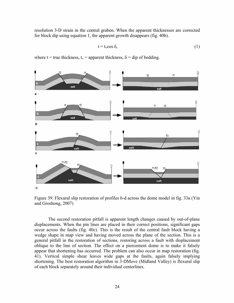
resolution 3-D strain in the central graben. When the apparent thicknesses are corrected for block dip using equation 1, the apparent growth disappears (fig. 40b).
t = tvcos δ, (1) where t = true thickness, tv = apparent thickness, δ = dip of bedding.
Figure 39. Flexural slip restoration of profiles b-d across the dome model in fig. 33a (Yin and Groshong, 2007) The second restoration pitfall is apparent length changes caused by out-of-plane displacements. When the pin lines are placed in their correct positions, significant gaps occur across the faults (fig. 40c). This is the result of the central fault block having a wedge shape in map view and having moved across the plane of the section. This is a general pitfall in the restoration of sections, restoring across a fault with displacement oblique to the line of section. The effect on a piercement dome is to make it falsely appear that shortening has occurred. The problem can also occur in map restoration (fig. 41). Vertical simple shear leaves wide gaps at the faults, again falsely implying shortening. The best restoration algorithm in 3-DMove (Midland Valley) is flexural slip of each block separately around their individual centerlines.

25
Figure 40. Flexural-slip restorations of profile b across the dome model in fig. 33a (modified from Yin and Groshong, 2006). a. Uncorrected profile. b. Thickness corrected using eq. 1. c. Length corrected by moving pin line to original location, leaving gaps across the faults.
Figure 41. Map restoration (Yin and Groshong, 2006). a. Original 3-d model. b. Correct restoration without any length changes. c. Vertical simple shear restoration leaves large gaps across faults. d. Flexural-slip restoration parallel to the center line of each block separately.
26
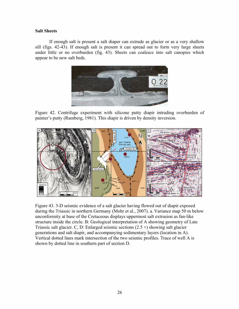
Salt Sheets If enough salt is present a salt diaper can extrude as glacier or as a very shallow sill (figs. 42-43). If enough salt is present it can spread out to form very large sheets under little or no overburden (fig. 43). Sheets can coalesce into salt canopies which appear to be new salt beds.
Figure 42. Centrifuge experiment with silicone putty diapir intruding overburden of painter’s putty (Ramberg, 1981). This diapir is driven by density inversion.
Figure 43. 3-D seismic evidence of a salt glacier having flowed out of diapir exposed during the Triassic in northern Germany (Mohr et al., 2007). a. Variance map 50 m below unconformity at base of the Cretaceous displays uppermost salt extrusion as fan-like structure inside the circle. B: Geological interpretation of A showing geometry of Late Triassic salt glacier. C, D: Enlarged seismic sections (2.5 ×) showing salt glacier generations and salt diapir, and accompanying sedimentary layers (location in A). Vertical dotted lines mark intersection of the two seismic profiles. Trace of well A is shown by dotted line in southern part of section D.

27
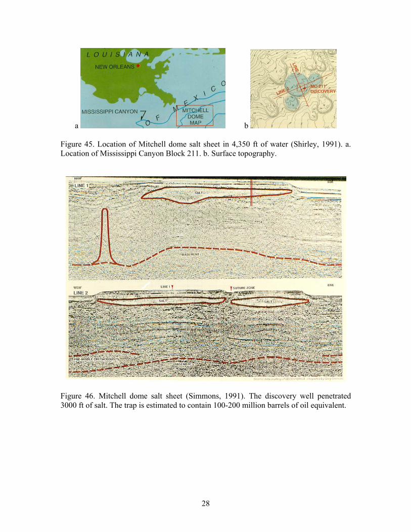
Figure 44. Formation of allochthonous salt sheets from diapiric feeders (Hudec and Jackson, 2006). Detached salt sheets were in the past thought to represent either episodes of salt deposition or the tops of huge salt massifs. Until fairly recently the seismic penetration was poor and the deep structure was unknown. Modern seismic reveals sediments below the salt, creating a major new play (figs. 45-47).
28
a b Figure 45. Location of Mitchell dome salt sheet in 4,350 ft of water (Shirley, 1991). a. Location of Mississippi Canyon Block 211. b. Surface topography.
Figure 46. Mitchell dome salt sheet (Simmons, 1991). The discovery well penetrated 3000 ft of salt. The trap is estimated to contain 100-200 million barrels of oil equivalent.

29
a
b Figure 47. The Princess field, a sub-salt discovery below allochthonous salt in the northern Gulf of Mexico (Bouma et al., 2006). a. Location map. b. 3D pre-stack depth migration done after the discovery based on a single 2-D line. This field is estimated to contain 175 million barrels of recoverable oil.

30
Salt sheets become the locus of a new round of salt tectonics. Sediments deposited over the top displace salt and subside to form mini-basins (figs. 48-49).
Figure 48. Salt nappe and developing minibasins (Rowan et al., 1999).
Figure 49. Sea floor topography in northern Gulf of Mexico minibasin province (Diegel et al., 1995).

31
Figure 50. Perched minibasin beginning to subside into salt (green) (Diegel et al., 1995). The minibasins move apart and are separated by normal faults (fig. 48). The salt uplift in the zone of extension (fig. 51) is a reactive diapir, being entirely the isostatic response to extension. The reactive nature of the diaper is indicated by a sag over the top, not an uplift as seen in an active diapir.
Figure 51. Dip section across fault zone between minibasins (Rowan et al., 1999). Subsidence above diapir indicates reactive origin.

32
Pseudoextension Pseudoextension is a term applied here to normal faults that form by rotation with little or no overall extension. The process was nicely described by Dailly (fig. 52) although he did not use this term. More recently the process has been recognized as being widespread and as applying to both salt and shale substrates.
Figure 52. Progradational sand wedge deposited on undercompacted shale leads to rotational subsidence of the sand and vertical displacement of the shale (Dailly, 1976). The major pseudoextensional fault systems described here develop from allochthonous sheets of salt or shale (fig. 53a). A Roho, named for C.C. Roripaugh’s moho (Schuster, 1995), is a thin band of high-amplitude discontinuous reflectors that form the base of most of the faults and allochthonous salt features. In the Gulf of Mexico, a roho fault system (fig. 53b) is a major, listric, down-to-basin growth fault that soles into an intra-Tertiary salt evacuation surface (known as a tertiaty salt weld). A stepped counter-regional fault system (fig. 53c) consists of major, listric, up-to-basin growth “faults” that sole into salt evacuation surfaces (welds).

33
Figure 53. Major fault styles related to allochthonous salt (Schuster, 1995). a. Allochthonous salt tablet. b. Roho system. c. Stepped counter-regional system.
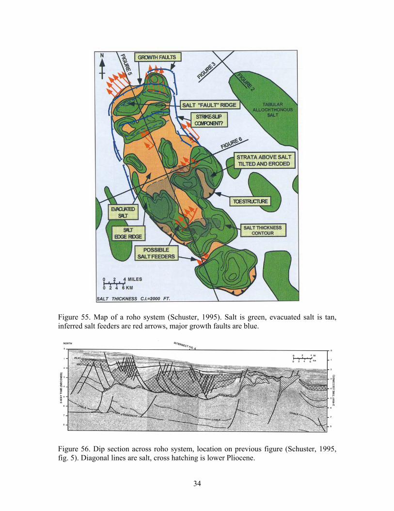
Roho fault system A roho system is, in effect, a large gravity glide toward deep water, accompanied by the evacuation of salt/sale from the glide horizon (figs. 54-59). The amount of strike slip along the margin of the area (fig. 58) must be small because the horizontal displacement of the cover is small.
Figure 54. Roho fault system (Rowan, 1999).
34
Figure 55. Map of a roho system (Schuster, 1995). Salt is green, evacuated salt is tan, inferred salt feeders are red arrows, major growth faults are blue.
Figure 56. Dip section across roho system, location on previous figure (Schuster, 1995, fig. 5). Diagonal lines are salt, cross hatching is lower Pliocene.

35
Figure 57. Strike section across roho system, location on fig. 55 (Schuster, 1995, fig. 6). Diagonal lines are salt, cross hatching is lower Pliocene.

36
Figure 58. Strike-slip fault along margin of roho block (Rowan et al., 1999).
FF = fault family

37
Figure 59. Evolution of the roho cross section shown in fig. 56 (Schuster, 1995).

38
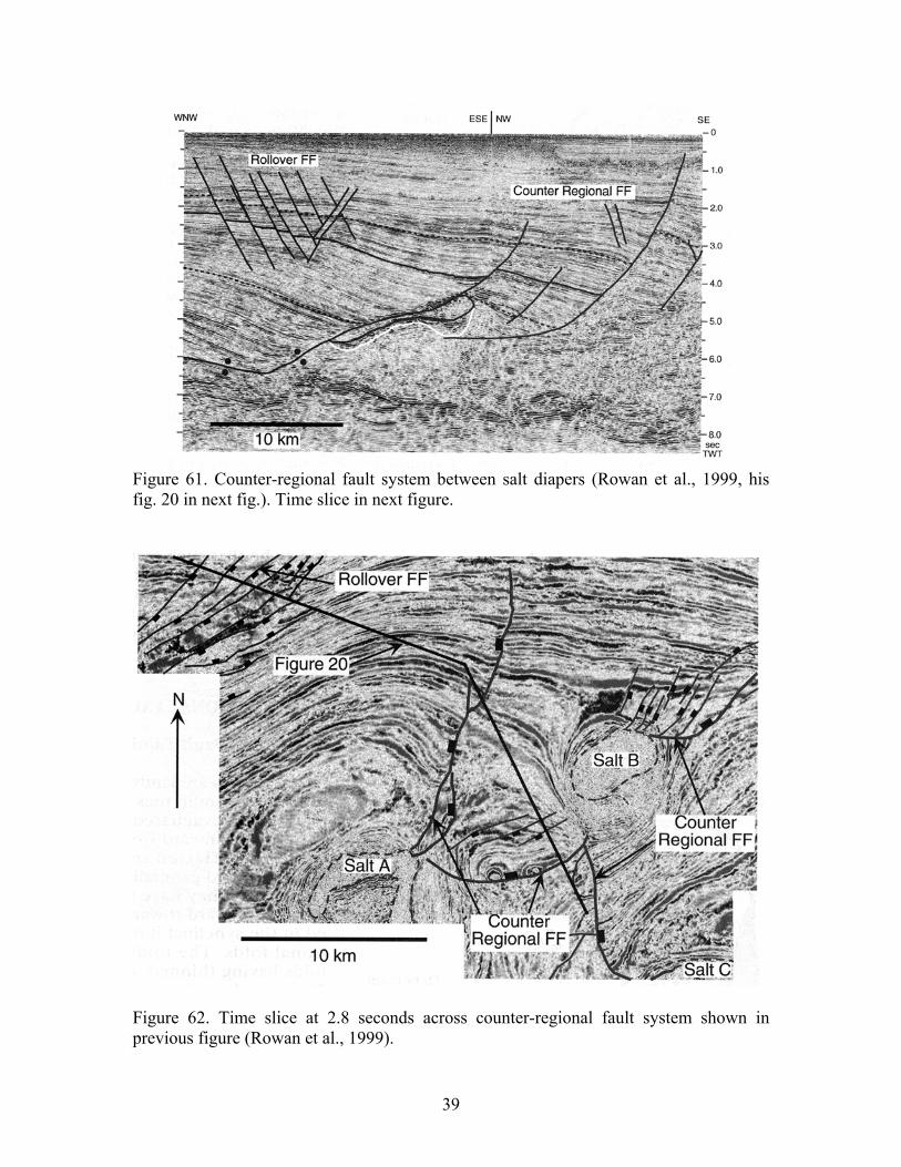
Stepped counter-regional fault system Major counter-regional fault systems (fig. 60) are the result of the evacuation of salt sills that cut obliquely up section in the downslope direction (figs. 61-62). Remnant salt along the ramp sections of the welds can form diapirs (figs. 63-67).
Figure 60. Structures associated with a stepped counter-regional fault system (Rowan et al., 1999).
39
Figure 61. Counter-regional fault system between salt diapers (Rowan et al., 1999, his fig. 20 in next fig.). Time slice in next figure.
Figure 62. Time slice at 2.8 seconds across counter-regional fault system shown in previous figure (Rowan et al., 1999).

40
Figure 63. Salt domes of southeast Louisiana (Schuster, 1995).
Figure 64. Profile A, fig. 63. Seismic dip section across Bourbon dome, Louisiana (Schuster, 1995).
41
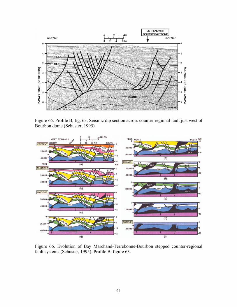
Figure 65. Profile B, fig. 63. Seismic dip section across counter-regional fault just west of Bourbon dome (Schuster, 1995).
Figure 66. Evolution of Bay Marchand-Terrebonne-Bourbon stepped counter-regional fault systems (Schuster, 1995). Profile B, figure 63.
42
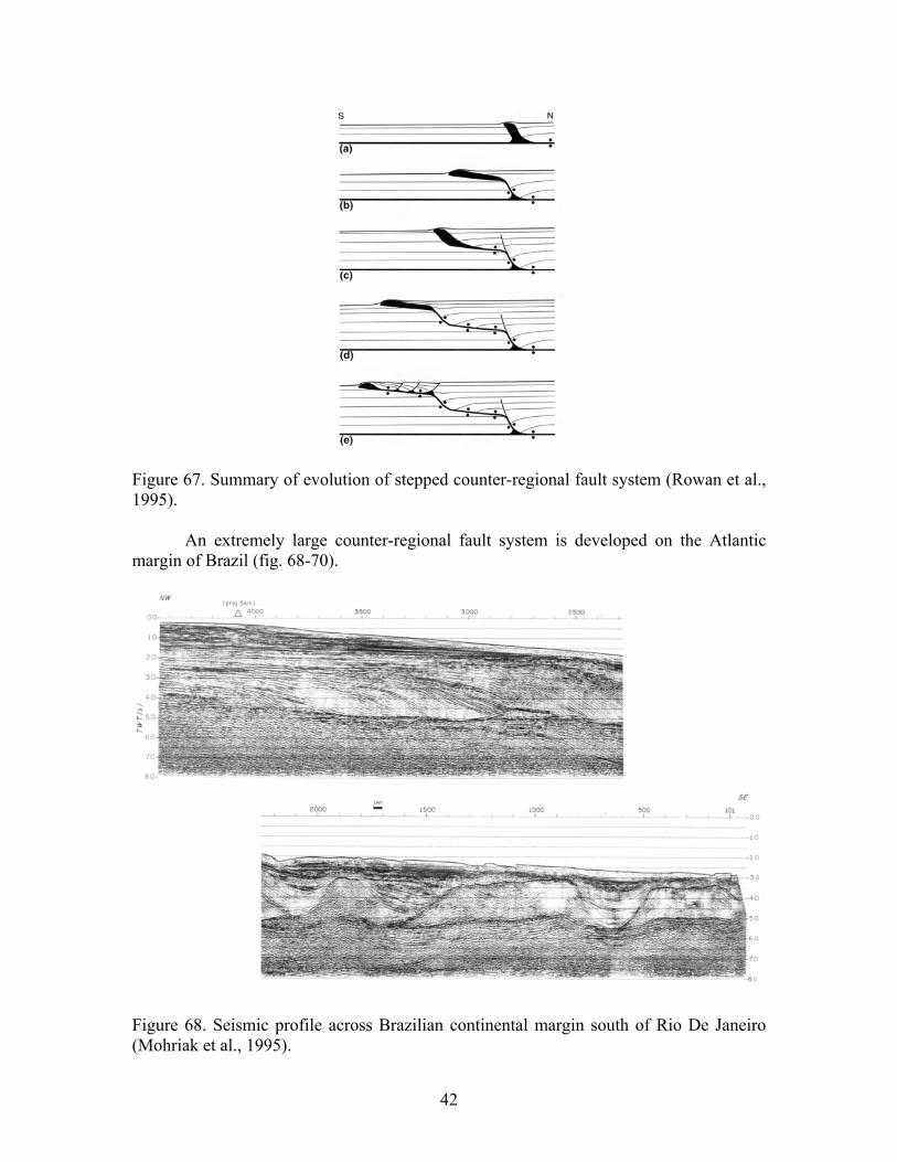
Figure 67. Summary of evolution of stepped counter-regional fault system (Rowan et al., 1995). An extremely large counter-regional fault system is developed on the Atlantic margin of Brazil (fig. 68-70).
Figure 68. Seismic profile across Brazilian continental margin south of Rio De Janeiro (Mohriak et al., 1995).
43
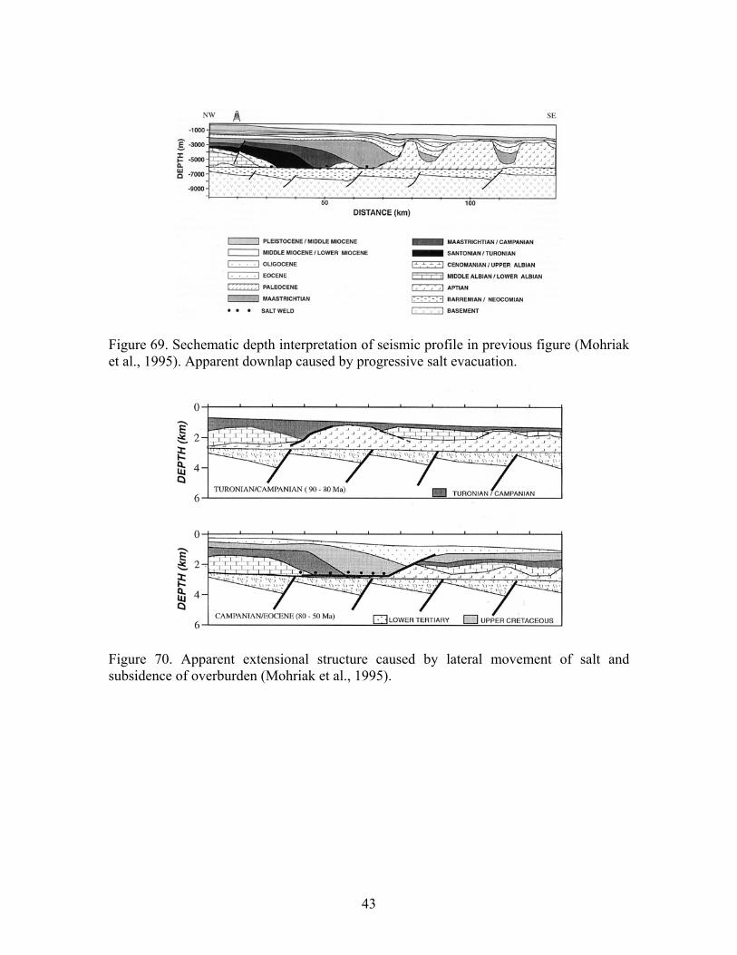
Figure 69. Sechematic depth interpretation of seismic profile in previous figure (Mohriak et al., 1995). Apparent downlap caused by progressive salt evacuation.
Figure 70. Apparent extensional structure caused by lateral movement of salt and subsidence of overburden (Mohriak et al., 1995).

44
Big Extension Large horizontal movement of the cover coupled to large vertical movemnets of a ductile substrate is what is here referred to as “big extension” in the context of vertical tectonics. The type example is the rafts on the Angola continental margin (figs. 71-73). Jackson (fig. 74). In such a feature, the lower unit is significantly younger than the stratigraphic age of the salt. The Lundin model (fig. 72) indicated that the faults bounding the two sides of the mock turtle are of different ages whereas the model of Jackson (fig. 74) has them the same age.
Figure 71. Progressive basinward graben development between large undeformed rafts (horsts) of the pre-tectonic cover sequence (Lundin, 1992).
Figure 72. Generalized cross section of salt withdrawal basin in the Gaivota Graben, Angola (Lundin, 1992). A = pre-salt sequence, B = raft sequence, C = growth sequence, C1 = core, C2 = landward-expanding sequence, C3 = seaward-expanding sequence.

45
Figure 73. Seismic time section in the raft domain of the Kwanza Basin, Angola (Hudec and Jackson, 2004).
Figure 74. The rise and fall of diapiric structures during extension (Jackson, 1995).

46
References Ajakaiye, D.E. and Bally, A.W., 2002, Course manual and atlas of structural styles on
reflection profiles from the Niger delta: AAPG Continuing Education Course Notes Series 41.
Armstrong, L.A., TenHave, A. and Johnson, H.D., 1987, The geology of the Gannet fields, central North Sea, UK sector, in J. Brooks and K.W. Glennie, eds., Petroleum Geology of North West Europe: Graham & Trotman, London, p. 533-548.
Atwater, G.I. and Foreman, M J., 1959, Nature of growth of southern Louisiana salt domes and its effect on petroleum accumulation: AAPG Bulletin, v. 43, p. 2592-2622.
Balk, R., 1936, Structure elements of domes: AAPG Bulletin, v.20, p. 51-67. Balk, R., 1949, Structure of Grand Saline salt dome, Van Zandt County, Texas: AAPG
Bulletin, v. 33, p. 1791-1829. Balk, R., 1953, Salt structures of Jefferson Island salt dome, Iberia and Vermillion
parishes, Louisiana: AAPG Bulletin, v. 37, p. 2455-2474. Bally, A.W., 1981, Thoughts on the tectonics of folded belts, in K.R. McClay and N.J.
Price, eds., Thrust and nappe tectonics: Geological Society of London Special Publication 9, p. 13-32.
Barde, J.P., Gralla, P., Harwijanto, J. and Marsky, J., 2002, Exploration at the eastern edge of the Precaspian basin: impact of data intergration on Upper Permian and Triassic prospectivity: AAPG Bulletin, v. 86, p. 399-415.
Barton, D.C., 1933, Mechanics of formation of salt domes with special reference to Gulf Coast salt domes of Texas and Louisiana: AAPG Bulletin, v. 17, p. 1025-1083.
Bates, F.W.; Copeland, R.R., Jr. and Dixon, K.P., 1959, Geology of Avery Island salt dome, Theria Paris Louisiana: AAPG Bulletin, v. 43, p. 944-957.
Biot, M.A., 1966, Three-dimensional gravity instability derived from two-dimensional solutions: Geophysics, v. 31, p. 153-166.
Bishop, R.S., 1977, Shale diapir emplacement in south Texas; Laward and Sherriff examples: Transactions of Gulf Coast Association of Geological Societies, v. 27, p.20-31.
Boigk, H., 1981. Erdoel und Erdoelgas in der Bundesrepublik Deutschland: Stuttgart, Springer-Verlag, 328 p.
Bouma, A.E., Hampton, B.D. and Hewett, B.M., 2006, The Princess discovery, sub-salt Gulf of Mexico: Challenges of sub-salt imaging in a fast-paced sub-sea development: Houston Geological Society Bulletin, v. 48, p. 35-37.
Brewer, R.C. and Groshong, R.H., Jr., 1993, Restoration of cross sections above intrusive salt domes: AAPG Bulletin, v. 77, p. 1769-1780.
Brewer, R.C. and Kenyon, P.M., 1996, Balancing salt dome uplift and withdrawal basin subsidence in cross-section: Journal of Structural Geology, v. 18, p. 493-504.
Brinkman, R. and Logters, H., 1968, Diapirs in western Pyrenees and foreland, Spain: AAPG, Memoir 8, p. 275-292.
Bullard, T., 1973, Eugine Island Block 126 field, in J. Braunstein et al., eds., Offshore Louisiana Oil and Gas Fields: Lafayette Geological Society, p. 61-64.

47
Camerlo, R.H., Meyer, D. and Meltz, R.E., 2005, Shale tectonics in the northern Port Isabel fold belt trend, deepwater Gulf of Mexico: Houston Geological Society Bulletin, v. 47, p. 57-59.
Carter, F.W., 1970, Geology of the salt anticline region in southwestern Colorado: United States Geological Survey Professional Paper 637, 80 p.
Currie, J.B., 1956, Role of concurrent deposition and deformation of sediments in development of salt-dome graben structures: AAPG Bulletin, v. 40, p. 1-16.
Dailly, G.C., 1976, A possible mechanism relating progradation, growth faulting, clay diapirism and overthrusting in a regressive sequence of sediments: Bulletin of Canadian Petroleum Geology, v. 24, p. 92-116.
Davis, D.C. and Lambert, E.H., Jr., 1963. Mesozoic-Paleozoic producing areas of Mississippi and Alabama, v. 2: Mississippi Geological Society, Jackson, Mississippi.
Davison, I., Insley, M., Harper, M., Weston, P., Blundell, D., McClay, K. and Quallington, A., 1993, Physical modelling of overburden deformation around salt diapirs: Tectonophysics, v. 228, p. 255-274.
Davison, I., Alsop, I., Birch, P., Elders, C., Evans, N., et al., 2000, Geometry and late-stage structural evolution of Central Graben salt diapirs, North Sea: Marine and Petroleum Geology, 2000, p. 499-522.
Dennis, H., Bergmo, P. and Holt, T., 2005, Tilted oil-water contacts: modeling the effects of aquifer heterogeneity: in Doré, A.G. and Vining, B.A., eds., Petroleum Geology: North-West Europe and Global Perspectives – Proceedings of the 6th Petroleum Geology Conference: Geological Society, London, p. 145-158.
Diegel, F.A., Karlo, J.F., Schuster, D.C., Shoup, R.C. and Tauvers, P.R., 1995, Cenozoic structural evolution and tectono-stratigraphic framework of the northern Gulf Coast continental margin, in Jackson, M.P.A., Roberts, D.G. and Snelson, S., eds., Salt tectonics: a global perspective: American Association of Petroleum Geologists Memoir 65, p. 109-151.
Dobrin, M.B., 1941, Some quantitative experiments on a fluid salt-dome model and their geological implications: American Geophysical Union Transactions, v. 22, p. 528-542.
Elston, D.P. and Shoemaker, E.M., 1963, Salt anticlines of the Paradox basin, Colorado and Utah: Symposium on Salt, 1963, Northern Ohio Geological Society, Cleveland, Ohio, p. 131-146.
Ewing, T.E., 1983, Growth faults and salt tectonics in the Houston diapir province relative timing and exploration significance: Transactions of Gulf Coast Association of Geological Societies, v. 33, p. 83-90.
Fails, T.G., 1992, Variation in diapiric structure development and productivity, northern Gulf Coast Basin: Transactions of Gulf Coast Association of Geological Societies, v. 42, p. 135-150.
Fletcher, R.C. and Hudec, M.R., 1996, Salt glacier and composite sediment-salt glacier models for the emplacement and early burial of allochthonous salt sheets, in Jackson, M.P.A., Roberts, D.G., and Snelson, S., eds., Salt tectonics: a global perspective: American Association of Petroleum Geologists Memoir 65, p. 77-108.
Fort, X., Brun, J.P. and Chauvel, F., 2004, Salt tectonics on the Angolan margin, synsedimentary deformation processes: AAPG Bulletin, v. 88, p. 1523-1544.

48
Garrison, L.E. and Martin, R.G., Jr., 1973, Geologic structures in the Gulf of Mexico basin: United States Geological Survey Professional Paper 773, p. 1-85.
Garwick, R.W.; Krisle, J.E. and Ellison, R.F., 1953, Esperson Dome field, Liberty and Harris Counties, Texas: AAPG-SEPM-SEG Guidebook Joint. Annual Meeting, Houston, Texas, p. 115-116.
Ge, H., Jackson, M.P.A. and Vendeville, B.C., 1997, Kinematics and dynamics of salt tectonics driven by progradation: AAPG Bulletin, v. 81, p. 398-423.
Giles, A.B., and Wood, D.R., 1983, Oakwood salt dome, east Texas: geologic framework growth history, and hydrocarbon production: Texas Bureau of Economic Geology, Geological Circular 83-1, 55 p.
Gilreath, J.A., 1968, Electric-log characteristics of diapiric shale: AAPG Memoir 8, p. 137-144.
Grinstead, F.E., 1962, Sugarland field, Fort Bend County, Texas: Typical Oil and Gas fields of Southeast Texas, Houston Geological Society, p. 219-220.
Gussow, W.C., 1968, Salt diapirism: importance of temperature, and energy source of emplacement: AAPG Memoir 8, p. 16-52.
Halbouty, M.T., 1967, Salt domes, Gulf Region, United States and Mexico: Gulf Publishing Co., Houston, 425 p.
Halbouty, M.T., 1979, Salt domes, Gulf region, United States and Mexico, Second Edition: Gulf Publishing Company, Houston, 561 p.
Heaton, R.C., Jackson, M.P.A., Bamahmoud, M. and Nani, A.S.O., 1995, Superposed Neogene extension, contraction, and salt canopy emplacement in the Yemeni Red Sea, in Jackson, M.P.A., Roberts, D.G. and Snelson, S., eds., Salt tectonics: a global perspective: AAPG Memoir 65, p. 331-351.
Hempton, M., Marshall, J., Sadler, S., Hogg, N., Charles, R. and Harvey, C., 2005, Turbidite reservoirs of the Sele Formation, Central North Sea: geological challenges for improving production, in Doré, A.G. and Vining, B.A., eds., Petroleum Geology: North-West Europe and Global Perspectives – Proceedings of the 6th Petroleum Geology Conference: Geological Society, London, p. 449-459.
Hooper, R.J. and Moore, C., 1995, Evaluation of some salt-related overburden structures in the U.K. southern North Sea, in Jackson, M.P.A., Roberts, D.G. and Snelson, S., eds., Salt tectonics: a global perspective: AAPG Memoir 65, p. 251-259.
Hospers, J., Rathore, J.S., Jianhua, F., Finnstrom, E.G. and Holthe, J., 1988, Salt tectonics in the Norwegian-Danish Basin: Tectonophysics, v. 149, p. 35-60.
Hossack, J.R., 1995, Geometric rules of section balancing for salt structures, in Jackson, M.P.A., Roberts, D.G. and Snelson, S., eds., Salt tectonics: a global perspective: AAPG Memoir 65, p. 29-40.
Hudec, M.R. and Jackson, M.P.A., 2004, Regional restoration across the Kwanza Basin, Angola: Salt tectonics triggered by repeated uplift of a metastable passive margin: AAPG Bulletin, v. 88, p. 971-990.
Hudec, M.R. and Jackson, M.P.A., 2006, Advance of allochthonous salt sheets in passive margins and orogens: AAPG Bulletin, v. 90, p. 1535-1564.
Hughes, D.J., 1968, Salt tectonics as related to several Smackover fields along the northeast rim of the Gulf of Mexico Basin: Transactions of the Gulf Coast Association of Geological Societies, v. 18, p. 320-330.

49
Hughes, M. and Davison, I., 1993, Geometry and growth kinematics of salt pillows in the southern North Sea: Tectonophysics, v. 228, p. 239-254.
Jackson, M.P.A., 1995, Retrospective salt tectonics, in Jackson, M.P.A., Roberts, D.G. and Snelson, S., eds., Salt tectonics: a global perspective: AAPG Memoir 65, p. 1-28.
Jackson, M. P.A. and Vendeville, B.C., 1994, Regional extension as a geologic trigger for diapirism: Geological Society of America Bulletin, v. 106, p. 57-73.
Jackson, M.P.A., Roberts, D.J. and Snelson, S., 1995, Salt Tectonics: A global perspective: AAPG Memoir 65, p. 454.
Jackson, M.P.A., Vendeville, B.C. and Schultz-Ela, D.D., 1994, Structural dynamics of salt systems: Annual Review of Earth and Planetary Sciences, v. 22.
Jackson, M.P.A., Cornelius, R.R., Craig, C.H., Gansser, A., Stocklin, J. and Talbot, C.J., 1990, salt diapirs of the Great Kavir, central Iran: Geological Society of America Memoir 177, 139 p.
Jenyon, M.K., 1986, Salt tectonics: Elsevier Applied Science Publishers, New York, 191 p.
Koyi, H., Talbot, C.J. and Tørudbakken, B.O., 1995, Salt tectonics in the northeastern Nordkapp Basin, southwestern Barents Sea, in Jackson, M.P.A., Roberts, D.G. and Snelson, S., eds., Salt tectonics: a global perspective: AAPG Memoir 65, p. 437-447.
Krzywiec, P., 2004, Triassic evolution of the Klodawa salt structure: Basement-controlled salt tectonics within the mid-Polish Trough (central Poland): Geological Quarterly, v. 48, p. 123-134.
Laudon, R.C., 1984, Evaporite diapirs in the La Popa basin, Nuevo Leon, Mexico: Geological Society of America Bulletin, v. 95, p. 1219-1225.
Liechti, P., 1968, Salt features of France, in R. Mattox, editor, Saline deposits: Geological Society of America Special Paper 88, p. 83-106.
Link, T.A., 1930, Experiments relating to salt-dome structure: AAPG Bulletin, v. 14, p. 483-508.
Lundin, E.R., 1992, Thin-skinned extensional tectonics on a salt detachment, northern kwanza Basin, Angola: Marine and Petroleum Geology, v. 9, p. 405-411.
Mais, W.R., 1957, Peripheral faulting at Bayou Blue salt dome, Iberville Parish, Louisiana: AAPG Bulletin, v. 41, p. 1915-1951.
Martinez, J.D., 1974, Tectonic behavior of evaporites, in Coogan, A.H., ed., Fourth Symposium on Salt, Volume 1: The Northern Ohio Geological Society, Cleveland, p. 155-168.
McDowell, A.N., 1951. The origin of the structural depression above Gulf Coast salt domes with particular reference to Clay Creek dome, Washington County, Texas: M.S. Thesis, Texas A&M University.
Mohr, M., Warren, J.K., Kukla, P.A., Urai, J.L. and Irmen, A., 2007, Subsurface seismic record of salt glaciers in an extensional intracontinental setting (Late Triassic of northwestern Germany): Geology, v. 35, p. 963-966.
Mohriak, W.U., Macedo, J.M., Castellani, R.T., Rangel, H.D., et al., 1995, Salt tectonics and structural styles in the deep-water province of the Cabo Frio region, Rio de Janeiro, Brazil, in Jackson, M.P.A., Roberts, D.G. and Snelson, S., eds., Salt tectonics: a global perspective: AAPG Memoir 65, p. 273-304.
Montgomery, S.L. and Ericksen, R.L., 1997, Dry Creek salt dome, Mississippi Interior Salt Basin: AAPG Bulletin, v. 81, p. 351-366.

50
Muelberger, W R., 1959, Internal structure of the Grand Saline salt dome, Van Zandt County, Texas: Texas Bureau of Economic Geology, Report of Investigations No. 38, p. 1-23.
Murray, G.E., 1966, Salt structure of Gulf of Mexico basin - a review: AAPG Bulletin, v. 50, p. 438-478.
Nettleton, L.L., 1943, Recent experimental and geophysical evidence of mechanics of salt-dome formation: AAPG Bulletin, v. 27, p. 51-63.
Nettleton, L.L., 1955, History of concepts of Gulf Coast salt dome formation: American AAPG Bulletin, v. 39, p. 2373-2383.
Nilsen, K.T., Vendeville, B.C. and Johansen, J.T., 1995, Influence of regional tectonics on halokinesis in the Nordkapp Basin, Barents Sea, in Jackson, M.P.A., Roberts, D.G. and Snelson, S., eds., Salt tectonics: a global perspective: AAPG Memoir 65, p. 413-436.
O'Brien, G.D., 1968, Survey of diapirs and diapirism: AAPG Memoir 8, p. 1-9. O'Niell, C.A., 1973. Evolution of Belle Isle Salt Dome, Louisiana. Gulf Coast
Association of Geological Societies, v. 23, p. 115-135 Oxley, M.L. and Herlihy, D.E., 1972, The Bryan field – a sedimentary anticline:
Geophysics, v. 37, p. 59-67. Parker, T.J. and McDowell, A.N., 1951, Scale models as guide to interpretation of salt-
dome faulting: AAPG Bulletin, v. 35, p. 2076-2094. Parker, T.J. and McDowell, A.N., 1955, Model studies of salt-dome tectonics: American
AAPG Bulletin, v. 39, p. 2384-2470. Peel, F.J., Travis, C.J. and Hossack, J.R., 1995,Genetic structural provinces and salt
tectonics of the Cenozoic offshore U. S. Gulf of Mexico: a preliminary analysis, in Jackson, M.P.A., Roberts, D.G. and Snelson, S., eds., Salt tectonics: a global perspective: AAPG 65, p. 153-175.
Qi, J., Pashin, J.C., and Groshong, R.H., Jr., 1998, Structure and evolution of North Choctaw Ridge Field, Alabama, a salt-related footwall uplift along the peripheral fault system, Gulf Coast Basin: Transactions of Gulf Coast Association of Geological Societies, v. 48, p. 349-359.
Ramberg, H., 1981, Gravity, deformation and the Earth's crust, second edition: Academic Press, London, 452 p.
Read, J.L., 1959, Geologic case history of Slocum Dome, Anderson County, Texas: AAPG Bulletin, v. 43, p. 958-973.
Rowan, M. G., 1995, Structural styles and evolution of allochthonous salt, central Louisiana Outer Shelf and Upper Slope, in Jackson, M.P.A., Roberts, D.G. and Snelson, S., eds., Salt tectonics: a global perspective: AAPG Memoir 65, p. 199-228.
Rowan, M.G. and Weimer, P., 1998, Salt-sediment interaction, northern Green Canyon and Ewing Bank (offshore Louisiana), northern Gulf of Mexico: AAPG Bulletin, v. 82 p. 1055-1082.
Rowan, M.G., Jackson, M.P.A. and Trudgill, B.D., 1999, Salt-related fault families and fault welds in the northern Gulf of Mexico: AAPG Bulletin, v. 83, p. 1454-1484.
Rowan, M.G., Lawton, T.F., Giles, K.A. and Ratliffe, R.A., 2003, Near-salt deformation in La Popa basin, Mexico, and the northern Gulf of Mexico: A general model for passive diapirism: AAPG Bulletin, v. 87, p. 733-756.

51
Sannemann, D., 1968, Salt-stock families in northwestern Germany: AAPG Memoir 8, p. 261-270.
Schemeling, H., Cruden, A.R. and Marquart, G., 1988, Finite deformation in and around a fluid sphere moving through a viscous medium: Implications for diapiric ascent: Tectonophysics, v. 149, p. 17-34.
Schmitz, J. and Flixeder, F., 1993, Structure of a classic chalk oil field and production enhancement by horizontal drilling, Reitbrook, NW Germany, in A.M. Spencer, ed., Generation, accumulation and production of Europe's hydrocarbons III, Special Publication of the European Association of Petroleum Geoscientists No. 3: Springer-Verlag, Berlin, p. 141-154.
Schultz-Ela, D.D., 2003, Origin of drag folds bordering salt diapers: AAPG Bulletin, v. 87, p. 757-780.
Schultz-Ela, D.D., Jackson, M.P.A. and Vendeville , B.C., 1993, Mechanics of active salt diapirism: Tectonophysics, v. 228, p. 275-312.
Schuster, D.C., 1995, Deformation of allochthonous salt and evolution of related salt-structural systems, eastern Louisiana Gulf Coast, in Jackson, M.P.A., Roberts, D.G. and Snelson, S., eds., Salt tectonics: a global perspective: AAPG Memoir 65, p. 177-198.
Seni, S.J. and Jackson, M.P.A., 1983, Evolution of salt structures, east Texas diapir province, part 1: Sedimentary record of halokinesis: AAPG Bulletin, v. 67, p. 1219-1244.
Seni, S.J. and Jackson, M.P.A. 1983, Evolution of salt structures, east Texas diapir province, part 2: Patterns and rates of halokinesis: AAPG Bulletin, v. 67, p. 1245-1274.
Shirley, K., 1991, Gulf gambles hit jackpot: AAPG Explorer, v. 12, p. 1, 6-7. Simmons, G., 1991, Study suggests salt traps in deep Gulf: AAPG Explorer, v. 12, p. 4. Steiner, R.J., 1976, Grand Isle Block 16 field, offshore Louisiana, in J. Braunstein, ed.,
AAPG Memoir 24, p. 229-238. Talbot, C.J., 1993, Spreading of salt structures in the Gulf of Mexico: Tectonophysics, v.
228, p. 151-166. Trusheim, F., 1960, Mechanism of salt migration in northern Germany: American AAPG
Bulletin, v. 44, p. 1519-1540. van Berkel, J.T., 1989, Deformation in the overburden of diapiric evaporite ridges:
examples from the Sverdrup Basin, Canadian Arctic Archipelago: Journal of Structural Geology, v. 11, p. 995-1006.
Vear, A., 2005, Deep-water plays of the Mauritanian continental margin, in Doré, A.G. and Vining, B.A., eds., Petroleum Geology: North-West Europe and Global Perspectives – Proceedings of the 6th Petroleum Geology Conference: Geological Society, London, p. 1217-1232.
Vendeville, B.C. and Jackson, M.P.A., 1992, The rise of diapirs during thin-skinned extension: Marine and Petroleum Geology, v. 9, p. 331-352.
Vendeville, B.C. and Jackson, M.P.A., 1992, The fall of diapirs during thin-skinned extension: Marine and Petroleum Geology, v. 9, p. 354-371.
Voitesti, I.P., 1925, Geology of the salt domes in the Carpathian region of Rumania: AAPG Bulletin, v. 9, p. 1165-1206.

52
Wallace, W.E., Jr., 1944, Structure of south Louisiana deep-seated domes: AAPG Bulletin, v. 28, p. 1249-1312.
Waltham, D., 1997, Why does salt start to move?: Tectonophysics, v. 282, p. 117-128. Weinberg, R.F. and Podladchikov, Y.Y., 1995, The rise of solid-state diapirs: Journal of
Structural Geology, v. 17, p. 1183-1195. Weston, P.J., Davison, I. and Insley, M.W., 1993, Physical modelling of North Sea salt
diapirism, in J.R. Parker, editor, Petroleum Geology of Northwest Europe: Proceedings of the 4th Conference: The Geological Society, London, p. 559-567.
Withjack, M.O. and Scheiner, C., 1982, fault patterns associated with domes--an experimental and analytical study: AAPG Bulletin, v. 66, p. 302-316.
Woodbury, H.O., Murray, I.B., Jr. and Osborne, R.E., 1980, Diapirs and their relation to hydrocarbon accumulation, in A.D. Miall, editor, Facts and Principles of World Petroleum Occurrence: Canadian Society of Petroleum Geology, Memoir 6, p. 119-142.
Wu, S., Bally, A.W. and Cramez, C., 1990, Allochthonous salt, structure and stratigraphy of the north-eastern Gulf of Mexico part II: Structure: Marine and Petroleum Geology, v. 7, p. 334-370.
Yin, H., 2003, Structural interpretation and validation of three-dimensional piercement structures: Ph.D. Dissertation, University of Alabama, Tuscaloosa, 150 p.
Yin, H. and Groshong, R.H., Jr., 2003, Geometric properties of active piercement structures: Geologic insights from 3-D kinematic models: Transactions of the Gulf Coast Association of Geological Societies, v. 53, p. 887-899.
Yin, H. and Groshong, R.H., Jr., 2006, Balancing and restoration of piercement structures: insights from 3-D kinematic models: Journal of Structural Geology, v. 28, p. 99-114.
Yin, H. and Groshong, R.H. Jr., 2007, A 3-D kinematic model for the deformation above an active diapir: AAPG Bulletin, v. 91, p. 343-363.