Embed Size (px)
Citation preview

598
Appendix
(12) Proportion and strength of ordinary concrete
Grade
Nominal
mix by
volume
Qty per 50kg of cement
Crushing strength of
15cm cubes in work
test
Fine
aggregate
m3
Coarse
aggregate
m3
Water
litres
7 days
Kg/cm2
28 days
Kg/cm2
M25 1:1:2 0.035 0.070 27 170 250
M20 1:1 1/2:3 0.530 0.106 30 135 200
M15 1:2:4 0.070 0.140 32 100 150
(13) R.C.C. Slabs for Culverts
Loading I.R.C. Class A Concrete 1:2:4 or M15
Clear
Span (m)
Overall
Depth
(cm)
Area of
Steel/m
(cm2)
Main rods No. of
rods
cranked
Distributor
Dia (mm) Spacing
(cm)
Diameter
(mm)
Spacing
(cm)
0.75 18 8.00 10 10 Nil 10 22
1.00 18 10.0 12 11 Nil 10 19
1.50 20 12.40 12 10 1 in 4 12 21.50
2.00 25 18.00 14 8.50 1 in 4 12 17.50
2.50 28 20.00 16 10 1 in 4 12 16.50
3.00 32 23.80 20 13 1 in 4 14 21.50
3.50 36 26.20 20 12 1 in 2 16 27
4.00 40 29.00 20 10.50 1 in 2 16 26
4.50 43 32.00 25 15.50 1 in 2 16 25
5.00 46 34.00 25 14.50 1 in 2 16 24
5.50 49 36.50 25 13.50 1 in 2 16 24
6.00 54 40.00 25 13 1 in 2 16 23
(14) Alternative table of R.C.C. slabs for culverts
Loading : IRC Class A Mild steel Gr. I
Span
m
Thickness
of slab
(overall)
cm
Longitudinal Bars Transverse Bars
Bottom Top Bottom Top
Dia
mm
Spacing cm Dia
mm
Spacing
cm
Dia
mm
Spacing cm Dia
mm
Spacing
cm M15 M20 M15 M20 M15 M20
1.0 19 15 16 15.0 11.5 10 30 16 15 12.5 10 30
1.5 22 18 16 10.5 9 10 30 16 15 10 10 30
2.0 24 21.5 16 10.0 8 10 30 16 12.5 10 10 30
2.5 27 24.5 16 9.0 7.5 10 30 16 12.5 15 10 30
3.0 30.5 27.5 16 7.5 7 10 30 16 12.5 15 10 30
3.5 34 31.5 16 6.0 6.5 10 30 16 12.5 15 10 30
4.0 37 34.5 20 10.0 9 10 30 16 12.5 15 10 30
5.0 42 39.5 20 9.0 7.5 10 30 16 12.5 15 10 30
6.0 47.5 44.5 20 7.5 6.8 10 30 16 12.5 15 10 30

Appendix
(15) Requirements of cement for different works
Ref
Schedule Particulars Quantity of cement
Brick Masonry(22.9cm x 11.2cm x 7.00 cm)
153 Brick work in CM 1:4, with wire cut bricks (19cm x
9cm x 9cm) 72 kg/m3
154 Brick work in CM 1:5, with wire cut bricks (19cm x
9cm x 9cm) 58 kg/m3
158 Brick work in CM 1:5, with country burnt bricks
(22.9cm x 11.2cm x 7.00 cm) 69 kg/m3
158(a) Brick work in CM 1:5, with country burnt bricks (19cm
x 9cm x 9cm) 69 kg/m3
159 Brick work in CM 1:6, with country burnt bricks (19cm
x 9cm x 9cm) 58 kg/m3
159(a) Brick work in CM 1:6, with country burnt bricks
(22.9cm x 11.2cm x 7.00 cm) 58 kg/m3
171 Brick work in CM 1:8, with country burnt bricks
(22.9cm x 11.2cm x 7.00 cm) 43 kg/m3
Laterite Masonry
205 Laterite masonry in CM 1:4 (44cm x 24cm x 14cm) 58 kg/m3
206 Laterite masonry in CM 1:5 (44cm x 24cm x 14cm) 46 kg/m3
206 Laterite masonry in CM 1:6 (44cm x 24cm x 14cm) 38 kg/m3
Rubble masonry
255 Cut stone work in steps 15 x 22 cm in CM 1:2 62 kg/m3
261 Coarsed Rubble work split stone in CM 1:2 101 kg/m3
264 Coarsed Rubble work split stone in CM 1:4 79 kg/m3
265 Coarsed Rubble work split stone in CM 1:5 63 kg/m3
272 Random rubble in CM 1:4 108 kg/m3
273 Random rubble in CM 1:5 86 kg/m3
274 Random rubble in CM 1:6 72 kg/m3
284 Random rubble in CM 1:8 54 kg/m3
Plastering
506 Plastering with CM 1:3, 6mm thick one coat 29 kg/10m2
506 Plastering with CM 1:3, 9mm thick one coat 43 kg/10m2
506 Plastering with CM 1:3, 12mm thick one coat 66 kg/10m2
510 Plastering with CM 1:3, 15mm thick one coat 72 kg/10m2
507 Plastering with CM 1:4, 12mm thick one coat 54 kg/10m2
511 Plastering with CM 1:4, 15mm thick one coat 59 kg/10m2
508 Plastering with CM 1:5, 12mm thick one coat 43 kg/10m2
509 Plastering with CM 1:6, 12mm thick one coat 36 kg/10m2
512 Plastering with CM 1:5, 15mm thick one coat 48 kg/10m2
513 Plastering with CM 1:6, 15mm thick one coat 40 kg/10m2
513 Plastering with CM 1:7, 12mm thick one coat 31 kg/10m2
514 Cement flushing coat, 12mm thick 22 kg/10m2
Cement concrete
110 CC 1:3:6 using 40mm (nominal size) broken stone 228 kg/m3
111 CC 1:4:8 using 40mm (nominal size) broken stone 171 kg/m3
112 CC 1:5:10 using 40mm (nominal size) broken stone 137 kg/m3
CC 1:4:7 using 40mm (nominal size) broken stone 195.43 kg/m3
600
Appendix
122 CC 1:2:4 using 20mm (nominal size) broken stone 33 kg/10dm3
122(a) CC 1:11/2:3 using 20mm (nominal size) broken stone 4.32 kg/10dm3
123 CC 1:3:6 using 20mm (nominal size) broken stone 2.16 kg/10dm3
124 CC 1:4:8 using 20mm (nominal size) broken stone 1.62 kg/10dm3
CC 1:3:6 using graded 60% 40mm & 40% 20mm bs 223.2 kg/m3
CC 1:4:7 using graded 60% 40mm & 40% 20mm bs 191.31 kg/m3
CC 1:3:6 using graded 50% 40mm & 50% 20mm bs 222 kg/m3
CC 1:3:6 using graded 70% 40mm & 30% 20mm bs 224.4 kg/m3
Pointing
526 Pointing brick work with CM 1:3 13.25 kg/10m2
527 Pointing brick work with CM 1:4 10.00 kg/10m2
528 Pointing tile flooring with CM 1:3 6.62 kg/10m2
531 Pointing RR masonry with CM 1:2 18.58 kg/10m2
532 Pointing RR masonry with CM 1:3 13.25 kg/10m2
533 Pointing RR masonry with CM 1:4 10.00 kg/10m2
534 Flesh pointing ashlar masonry with CM 1:2 9.29 kg/10m2
535 Flesh pointing ashlar masonry with CM 1:3 6.62 kg/10m2
(16) Stripping Time for formwork (I.S. 456-2000)
Sl No. Type of formwork Min. Period
1 Vertical formwork to columns, walls and beams 16-24 hours
2 Soffit formwork to slabs (props to be refixed
immediately after removal of formwork)
3 days
3 Soffit formwork to beams (props to be refixed
immediately after removal of formwork)
7 days
4 Props to slabs
1. Spanning up to 4.5m
2. Spanning over 4.5m
7 days
14 days
5 Props to beams and arches
1. Spanning up to 6m
2. Spanning over 6m
14 days
21 days
In normal circumstances where ambient temperature does not fall below 15oC and where ordinary
Portland cement is used and adequate curing is done
(17) Covering capacity of paints
Lead primer on wood 9-11 m2/ litre
Lead primer on metal 9-13 m2/ litre
Flat undercoating 10-12 m2/ litre
Gloss painting 9-13 m2/ litre
Enamel 9-13 m2/ litre
Varnish 1st coat 11-13 m2/ litre
Varnish 2nd coat 13-18 m2/ litre
Water paint and oil bound
distemper cover approximately
6-8 m2/kg
Appendix
(18) Coefficient for measurements of painting
602
Appendix
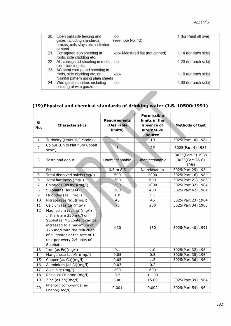
(19) Physical and chemical standards of drinking water (I.S. 10500:1991)
Sl
No.
Characteristics
Requirements
(Desirable
limits)
Permissible
limits in the
absence of
alternative
source
Methods of test
1 Turbidity (Units JDC Scale) 5 10 3025(Part 10) 1984
2 Colour (Units Platinum Cobalt
scale) 5 25 3025(Part 4) 1983
3
Taste and odour
Unobjectionable
Unobjectionable
3025(Part 5) 1983
3025(Part 7& 8)
1984
4 PH 6.5 to 8.5 No relaxation 3025(Part 25) 1984
5 Total dissolved solids (mg/l) 500 2000 3025(Part 16) 1984
6 Total hardness (mg/l) 300 600 3025(Part 21) 1983
7 Chlorides (as mg)(mg/l) 250 1000 3025(Part 32) 1984
8 Sulphates (as SO4) 200 400 3025(Part 42) 1984
9 Fluorides (as F mg l) 1.0 1.5 10 Nitrates (as No3)(mg/l) 45 45 3025(Part 23) 1964
11 Calcium (as Ca)(mg/l) 75 200 3025(Part 34) 1988
12 Magnesium (as mg)(mg/l)
If there are 250 mg/l of
Suphates, Mg content can be
increased to a maximum of
125 mg/l with the reduction
of sulphates at the rate of 1
unit per every 2.5 units of
Sulphates
<30
150
3025(Part 40) 1991
13 Iron (as Fe)(mg/l) 0.1 1.0 3025(Part 32) 1984
14 Manganese (as Mn)(mg/l) 0.05 0.5 3025(Part 35) 1964
15 Copper (as Cu)(mg/l) 0.05 1.5 3025(Part 36) 1964
16 Aluminium (as Al)(mg/l) 0.03 0.2 17 Alkalinity (mg/l) 200 600 18 Residual Chlorine (mg/l) 0.2 >1.00 19 Zinc (as Zn)(mg/l) 5.00 15.00 3025(Part 39) 1964
20 Phenolic compounds (as
Phenol)(mg/l) 0.001 0.002 3025(Part 54) 1964

21 Anionic detergents (mg/l)
(MBAS) 0.02 1.0
Methylene – blue
extraction method

604
Appendix
22
Mineral oil (mg/l)
0.01
0.03
Gas
chromatographic
method
Toxic materials 23 Arsenic (as As)(mg/l) 0.01 0.05 3025(Part 37) 1988
24
Cadmium (as Cd)(mg/l)
0.01
0.01
Atomic absorption
spectrophotometric
method
25 Chromium (as Hexavalent
Cr)(m/l) 0.05 0.05 3025(Part 38) 1964
26 Cyanides (as Cd)(mg/l) 0.05 0.05 3025(Part 27) 1986
27
Lead (as Pb)(mg/l)
0.05
0.05
Atomic absorption
spectrophotometric
method
28 Selenium (as Se)(mg/l) 0.01 0.01 3025(Part 28) 1964
29 Mercury (Total as Hg)(mg/l) 0.001 0.001 Mercury ion
analyser
30 Poly nuclear aromatic
hydrocarbons (PAH) 0.2 µg/l 0.2 µg/l
Radio activity 31 Gross Alpha activity (Bq/l) 0.1 0.1 32 Gross Beta Activity (Bq/l) 1.0 1.0
(20) Recommended per capita water supply levels for design
of schemes
SI No Classification of Towns / Cities Recommended maximum
water supply levels
1
Towns provided with piped water supply but without
sewerage system
70
2 Cities provided with piped water supply where sewerage
system is existing/contemplated 135
3 Metropolitan and mega cities provided with piped water
supply where sewerage system is existing/contemplated
150
(21) Recommended water supply levels for institutions
SI
No Institutions Litres per head per day
1
Hospitals (including laundry)
a)No. of beds exceeding 100
b) No. of beds not exceeding 100
450 (per bed)
340 (per bed)
2 Hotels 180 (per bed)
3 Hostels 135
4 Nurse’s homes and medical quarters 135
5 Boarding Schools/ Colleges 135

6 Restaurants 70 (per bed)

606
Appendix
7 Airports and seaports 70
8
Junction stations and intermediate stations where mail
or express stoppage (both railways and bus stations) is
provided
70
9 Terminal stations 45
10
Intermediate stations (Excluding mail and express
stops)
45 (could be reduced to 25
where bathing facilities are not
provided)
11 Day Schools/ Colleges 45
12 Offices 45
13
Factories
45 (could be reduced to 30
where no bathrooms are
provided)
14 Cinema, concert halls and theatre 15
(22) Recommended water requirements for Domestic & Non-
Domestic needs
Sl No Description Amount of water (lpcd)
1 For communities with population upto 20,000
a) Water supply through stand post
b) Water supply through house supply connection
40 (min)
70 to 100
2 For communities with population 20,000 to 1,00,000 100 to 150
3 For communities with population above 1,00,000 150 to 200
(23) Design period for the components in water supply schemes
Sl No Items Design Period ( in years)
1 Storage by dams 50
2 Infiltration works 30
3 Pumping
1. Pump house (Civil Works)
2. Electric Motors and Pumps
30
15
4 Water Treatment units 15
5 Pipe connection to several treatment units
and other small appurtenances
30
6 Raw water and clear water conveying mains 30
7 Clear water reservoirs at the head works,
balancing tanks and service reservoirs
(overhead or ground level)
15
8 Distribution system 30

Appendix
(24) Design data for small RCC square water tank
Cap
acit
y in
litr
es
Len
gth
x
Breadth
in
sid
e
in m
Dep
th
inclu
din
g f
ree
bo
ard in
cm
Th
ickn
ess o
f
walls a
nd f
loo
r
in c
m
Reinforcements
Walls Floor
Hori. steel Vert. steel Bars each way
Bars c Bars a&b Bars d
Dia
(mm
)
Sacing
(cm)
Dia
(mm)
Sacing
(cm)
Dia
(mm)
Sacing (cm)
2000
3500
5000
7000
9000
14000
23000
1.5x1.
5
1.8x1.
8
2.0x2.
0
2.3x2.
3
2.5x2.
5
2.8x2.
8
3.5x3.
5
1.00
1.25
1.40
1.50
1.60
2.00
2.10
10
10
10
11.5
11.5
13
15
6
6
6
10
10
10
10
15
15
15
22
20
18
16
6
6
6
10
10
12
16
15
15
15
22
15
18
20
6
6
6
6
6
6
6
20
20
20
20
20
14
12
Note: Horizontal reinforcement can be reduced towards the top to about 2/3 of the bottom
reinforcement, and thickness of walls can also be diminished towards the top.
Light reinforcement should be provided at the top in the floor slab
Bars (a) & (b) are alternate and the distance between each bars will be half of the spacing given.
Small RCC square water tank
(25) Location and requirements of wells
(National Building code 2005)
The well shall be located
1. Not less than 15m from any ash pit, refuse pit, earth closet or privy and shall be located on a
site upward from the earth closet or privy.
2. Not less than 18m from any cess pit soakway or borehole latrine.
3. That contamination by the movement of subsoil or other water is unlikely .

608
Appendix
The well shall
1. Have a minimum internal diameter of not less than 1m
2. Be constructed to a height not less than 1m above the surrounding ground level to form a
parapet or kerb to and to prevent surface water from flowing into a well
3. Be of sound and permanent construction throughout. Temporary or exposed wells shall be
permitted only in fields or gardens for purposes of irrigation
4. Have the interior surface of the lining or walls of the well be rendered impervious for a depth
of not less than 1.8m measured from the level of the ground immediately adjoining the well-
head.
(26) Location and requirements of septic tanks
(National building code 2005)
1. Septic tanks shall have a minimum width of 75cm, minimum depth of 1m below the water
level and a minimum liquid capacity of 1m3. The length of the tanks shall be 2 to 4 times the
width.
2. Septic tanks may be constructed of brickwork, stone masonry, concrete or other suitable
materials as approved by the authority.
3. The minimum nominal diameter of the pipe shall be 100mm.
4. The gradient of land drains, under drainage as well as the bottom of the dispersion trenches
and soak ways shall be between 1:300 and 1:400.
5. Every septic tank shall be provided with ventilating pipe of at least 50mm diameter.
(27) Design of drainage system
1. Allow for a flow of liquid waste from the buildings at the rate of 0.03 m3/min/100 persons
2. The minimum velocity in drain pipes shall be 0.75 m/sec. The drain pipes shall be half full at
peak flow. Velocity shall not exceed 2.4 m/sec.
3. Pipe diameter shall not be less than 100mm.
4. Gradients of various pipe sizes and discharges are as follows:-
Velocity Pipe dia Gradient
0.75 m/s 100 1 in 35
0.75 m/s 150 1 in 65
0.75 m/s 230 1 in 120
0.75 m/s 300 1 in 200
(28) Standards for sanitary arrangements (National Building Code)
For males For females
Office buildings
Water closet 1 for every 25 persons 1 for every 15 persons
or part thereof
Urinals Nil up to 6 persons
1 for 7-20 persons
2 for 21-45 persons
3 for 46-70 persons
4 for 71-100 persons
Wash basins 1 for every 25 persons
or part thereof
Hospitals

Water closet For males and females
1 for every 8 beds or part thereof

610
Appendix
2 up to 30 beds, add1 for every additional 30 beds
Theatres
Water closets 1 for every 100, above 400 add 1
for every 250
2 for every100, above 400 add
1 for every 100
Urinals 1 for every 50 Wash basins 1 for every 200 1 for every 20
Schools
Water closets 1 for every 4 pupils or part thereof 1 for every 25 pupils or part
thereof
Urinals 1 for every 40 pupils or part thereof Wash basins 1 for every 40 pupils or part thereof 1 for every 40 pupils or part
thereof
(29) Size of septic tanks (IS: 2470)
No. of users Length (m) Width (m) Liquid Depth for cleaning in
1 year interval 2 year interval
Domestic Tanks
5 1.50 0.75 1.00 1.05
10 2.00 0.90 1.00 1.40
15 2.00 0.90 1.30 1.80
20 2.30 1.10 1.30 1.80
50 4.00 1.40 1.30 2.00
Tanks for Hostels and Boarding School
50 5.00 1.60 1.30 1.40
100 5.70 2.10 1.40 1.70
150 7.70 2.40 1.40 1.70
200 8.90 2.70 1.40 1.70
300 10.70 3.30 1.40 1.70
Air space of 30cm above storage level to be provided
Floor should be of cement concrete of grade M15 and sloped towards sludge cleaning end
The capacity designed is inclusive of waste water from bath room, sink etc.
Certain authorities recommend not to let in waste water to the septic tank and to limit the size to
obtain a capacity of 0.092 m3/users (KESA)
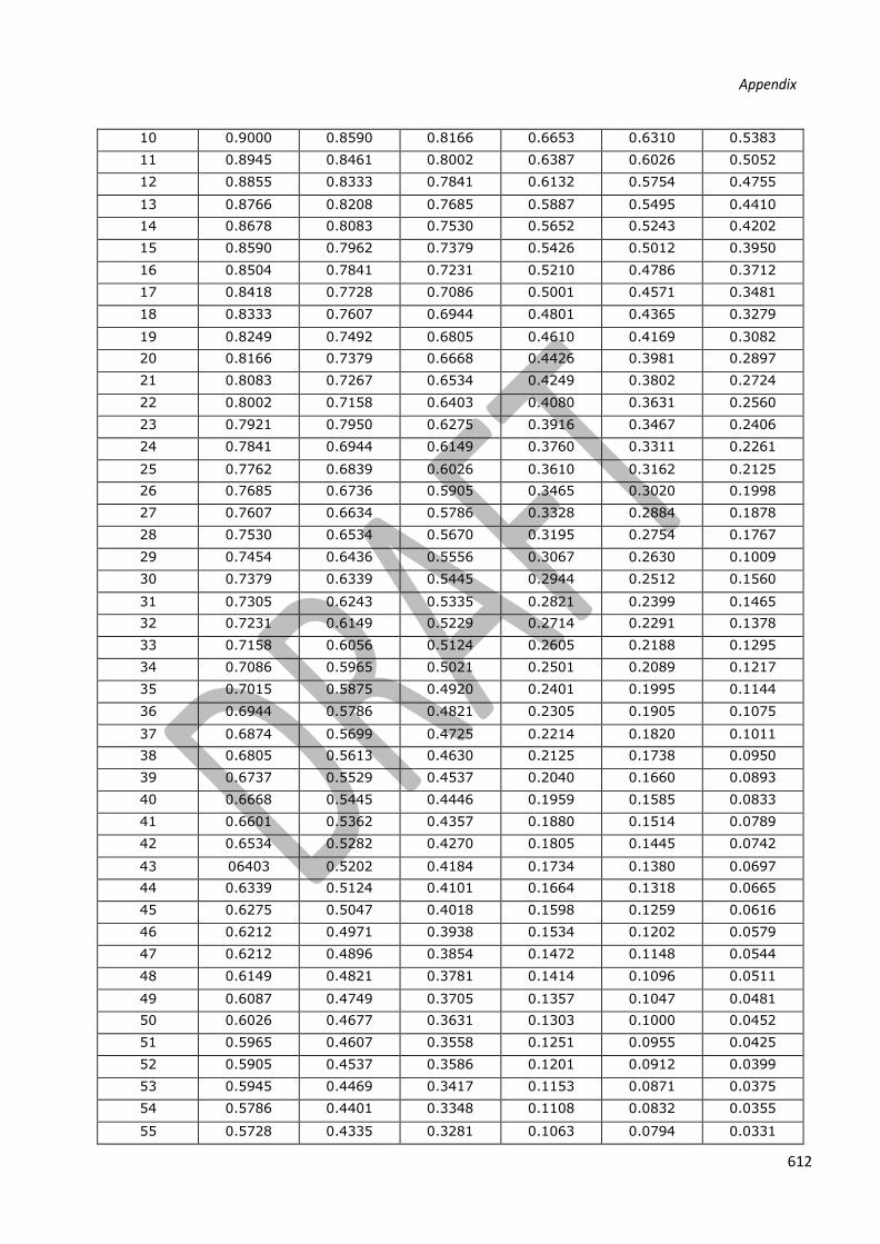
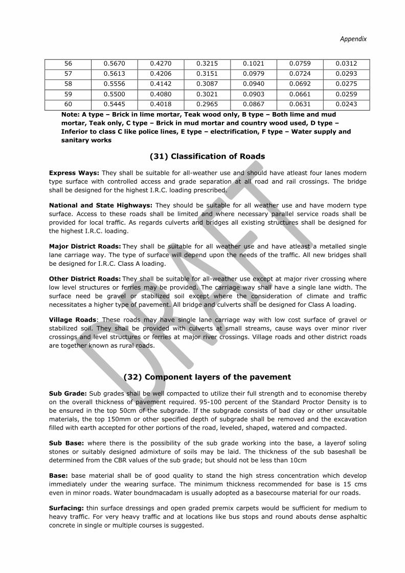
(30) Depreciated Value per rupee of Capital Cost of Building
No. of
Years
Depreciation Constant
A
1.0%
B
1.5%
C
2.0%
D
4.0%
E
4 ½%
F
6%
1 0.9000 0.9000 0.9000 0.9000 0.9000 0.9000
2 0.9000 0.9000 0.9000 0.9000 0.9000 0.8835
3 0.9000 0.9000 0.9000 0.8849 0.8710 0.8305
4 0.9000 0.9000 0.9000 0.8496 0.8318 0.7805
5 0.9000 0.9000 0.9000 0.8156 0.7943 0.7336
6 0.9000 0.9000 0.8855 0.7830 0.7586 0.6896
7 0.9000 0.8991 0.8678 0.7518 0.7244 0.6482
8 0.9000 0.8853 0.8504 0.7218 0.6918 0.6092

9 0.9000 0.8722 0.8333 0.6929 0.6607 0.5727
612
Appendix
10 0.9000 0.8590 0.8166 0.6653 0.6310 0.5383
11 0.8945 0.8461 0.8002 0.6387 0.6026 0.5052
12 0.8855 0.8333 0.7841 0.6132 0.5754 0.4755
13 0.8766 0.8208 0.7685 0.5887 0.5495 0.4410
14 0.8678 0.8083 0.7530 0.5652 0.5243 0.4202
15 0.8590 0.7962 0.7379 0.5426 0.5012 0.3950
16 0.8504 0.7841 0.7231 0.5210 0.4786 0.3712
17 0.8418 0.7728 0.7086 0.5001 0.4571 0.3481
18 0.8333 0.7607 0.6944 0.4801 0.4365 0.3279
19 0.8249 0.7492 0.6805 0.4610 0.4169 0.3082
20 0.8166 0.7379 0.6668 0.4426 0.3981 0.2897
21 0.8083 0.7267 0.6534 0.4249 0.3802 0.2724
22 0.8002 0.7158 0.6403 0.4080 0.3631 0.2560
23 0.7921 0.7950 0.6275 0.3916 0.3467 0.2406
24 0.7841 0.6944 0.6149 0.3760 0.3311 0.2261
25 0.7762 0.6839 0.6026 0.3610 0.3162 0.2125
26 0.7685 0.6736 0.5905 0.3465 0.3020 0.1998
27 0.7607 0.6634 0.5786 0.3328 0.2884 0.1878
28 0.7530 0.6534 0.5670 0.3195 0.2754 0.1767
29 0.7454 0.6436 0.5556 0.3067 0.2630 0.1009
30 0.7379 0.6339 0.5445 0.2944 0.2512 0.1560
31 0.7305 0.6243 0.5335 0.2821 0.2399 0.1465
32 0.7231 0.6149 0.5229 0.2714 0.2291 0.1378
33 0.7158 0.6056 0.5124 0.2605 0.2188 0.1295
34 0.7086 0.5965 0.5021 0.2501 0.2089 0.1217
35 0.7015 0.5875 0.4920 0.2401 0.1995 0.1144
36 0.6944 0.5786 0.4821 0.2305 0.1905 0.1075
37 0.6874 0.5699 0.4725 0.2214 0.1820 0.1011
38 0.6805 0.5613 0.4630 0.2125 0.1738 0.0950
39 0.6737 0.5529 0.4537 0.2040 0.1660 0.0893
40 0.6668 0.5445 0.4446 0.1959 0.1585 0.0833
41 0.6601 0.5362 0.4357 0.1880 0.1514 0.0789
42 0.6534 0.5282 0.4270 0.1805 0.1445 0.0742
43 06403 0.5202 0.4184 0.1734 0.1380 0.0697
44 0.6339 0.5124 0.4101 0.1664 0.1318 0.0665
45 0.6275 0.5047 0.4018 0.1598 0.1259 0.0616
46 0.6212 0.4971 0.3938 0.1534 0.1202 0.0579
47 0.6212 0.4896 0.3854 0.1472 0.1148 0.0544
48 0.6149 0.4821 0.3781 0.1414 0.1096 0.0511
49 0.6087 0.4749 0.3705 0.1357 0.1047 0.0481
50 0.6026 0.4677 0.3631 0.1303 0.1000 0.0452
51 0.5965 0.4607 0.3558 0.1251 0.0955 0.0425
52 0.5905 0.4537 0.3586 0.1201 0.0912 0.0399
53 0.5945 0.4469 0.3417 0.1153 0.0871 0.0375
54 0.5786 0.4401 0.3348 0.1108 0.0832 0.0355
55 0.5728 0.4335 0.3281 0.1063 0.0794 0.0331
Appendix
56 0.5670 0.4270 0.3215 0.1021 0.0759 0.0312
57 0.5613 0.4206 0.3151 0.0979 0.0724 0.0293
58 0.5556 0.4142 0.3087 0.0940 0.0692 0.0275
59 0.5500 0.4080 0.3021 0.0903 0.0661 0.0259
60 0.5445 0.4018 0.2965 0.0867 0.0631 0.0243
Note: A type – Brick in lime mortar, Teak wood only, B type – Both lime and mud
mortar, Teak only, C type – Brick in mud mortar and country wood used, D type –
Inferior to class C like police lines, E type – electrification, F type – Water supply and
sanitary works
(31) Classification of Roads
Express Ways: They shall be suitable for all-weather use and should have atleast four lanes modern
type surface with controlled access and grade separation at all road and rail crossings. The bridge
shall be designed for the highest I.R.C. loading prescribed.
National and State Highways: They should be suitable for all weather use and have modern type
surface. Access to these roads shall be limited and where necessary parallel service roads shall be
provided for local traffic. As regards culverts and bridges all existing structures shall be designed for
the highest I.R.C. loading.
Major District Roads: They shall be suitable for all weather use and have atleast a metalled single
lane carriage way. The type of surface will depend upon the needs of the traffic. All new bridges shall
be designed for I.R.C. Class A loading.
Other District Roads: They shall be suitable for all-weather use except at major river crossing where
low level structures or ferries may be provided. The carriage way shall have a single lane width. The
surface need be gravel or stabilized soil except where the consideration of climate and traffic
necessitates a higher type of pavement. All bridge and culverts shall be designed for Class A loading.
Village Roads: These roads may have single lane carriage way with low cost surface of gravel or
stabilized soil. They shall be provided with culverts at small streams, cause ways over minor river
crossings and level structures or ferries at major river crossings. Village roads and other district roads
are together known as rural roads.
(32) Component layers of the pavement
Sub Grade: Sub grades shall be well compacted to utilize their full strength and to economise thereby
on the overall thickness of pavement required. 95-100 percent of the Standard Proctor Density is to
be ensured in the top 50cm of the subgrade. If the subgrade consists of bad clay or other unsuitable
materials, the top 150mm or other specified depth of subgrade shall be removed and the excavation
filled with earth accepted for other portions of the road, leveled, shaped, watered and compacted.
Sub Base: where there is the possibility of the sub grade working into the base, a layerof soling
stones or suitably designed admixture of soils may be laid. The thickness of the sub baseshall be
determined from the CBR values of the sub grade; but should not be less than 10cm
Base: base material shall be of good quality to stand the high stress concentration which develop
immediately under the wearing surface. The minimum thickness recommended for base is 15 cms
even in minor roads. Water boundmacadam is usually adopted as a basecourse material for our roads.
Surfacing: thin surface dressings and open graded premix carpets would be sufficient for medium to
heavy traffic. For very heavy traffic and at locations like bus stops and round abouts dense asphaltic
concrete in single or multiple courses is suggested.
614
Appendix
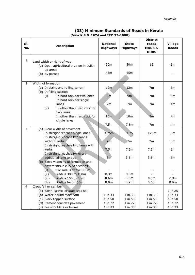
(33) Minimum Standards of Roads in Kerala
(Vide K.S.S. 1974 and IRC:73-1980)
Sl.
No.
Description
National
Highways
State
Highways
District
roads
MDRS &
ODRS
Village
Roads
1
Land width or right of way
(a) Open agricultural area on in built
up areas
(b) By passes
30m
45m
30m
45m
15
8m
-
2 Width of formation
(a) In plains and rolling terrain
(b) In filling section
(i) In hard rock for two lanes
In hard rock for single
lanes
(ii) In other than hard rock for
two lanes
In other than hard rock for
single lanes
12m
9m
7m
10m
7.5m
12m
9m
7m
10m
7.5m
7m
7m
7m
7m
7m
6m
4m
4m
4m
4m
3 (a) Clear width of pavement
In straight reaches single lanes
In straight reaches two lanes
without kerbs
In straight reaches two lanes with
kerbs
In straight reaches for every
additional lane to add
(b) Extra widening of formation and
pavements in curved sections
(i) For radius above 300m
(ii) Radius 300 to 150m
(iii) Radius 150 to 60m
(iv) Radius below 60m
3.75m
7m
7.5m
3m
-
0.3m
0.6m
0.9m
3.75
7m
7.5m
3.5m
-
0.3m
0.6m
0.9m
3.75m
7m
7.5m
3.5m
-
-
0.3m
0.6m
3m
3m
3m
3m
-
-
0.3m
0.6m
4 Cross fall or camber
(a) Earth, gravel or stabilized soil
(b) Water-bound macadam
(c) Black topped surface
(d) Cement concrete pavement
(e) For shoulders or berms
-
1 in 33
1 in 50
1 in 72
1 in 33
-
1 in 33
1 in 50
1 in 72
1 in 33
-
1 in 33
1 in 50
1 in 72
1 in 33
1 in 25
1 in 33
1 in 50
1 in 72
1 in 33

5 Gradient
(a) In planes and rolling terrain
(i) Ruling gradient
(ii) Limiting or maximum
Allowable gradient
(iii) Exceptional or absolute
maximum gdt to be
adopted for short
distances not exceeding
60m in a km
(a) In hills
1 in 30
1 in 20
1 in 15
1 in 30
1 in 20
1 in 15
1 in 30
1 in 15
1 in 12
1 in 20
1 in 15
1 in 12
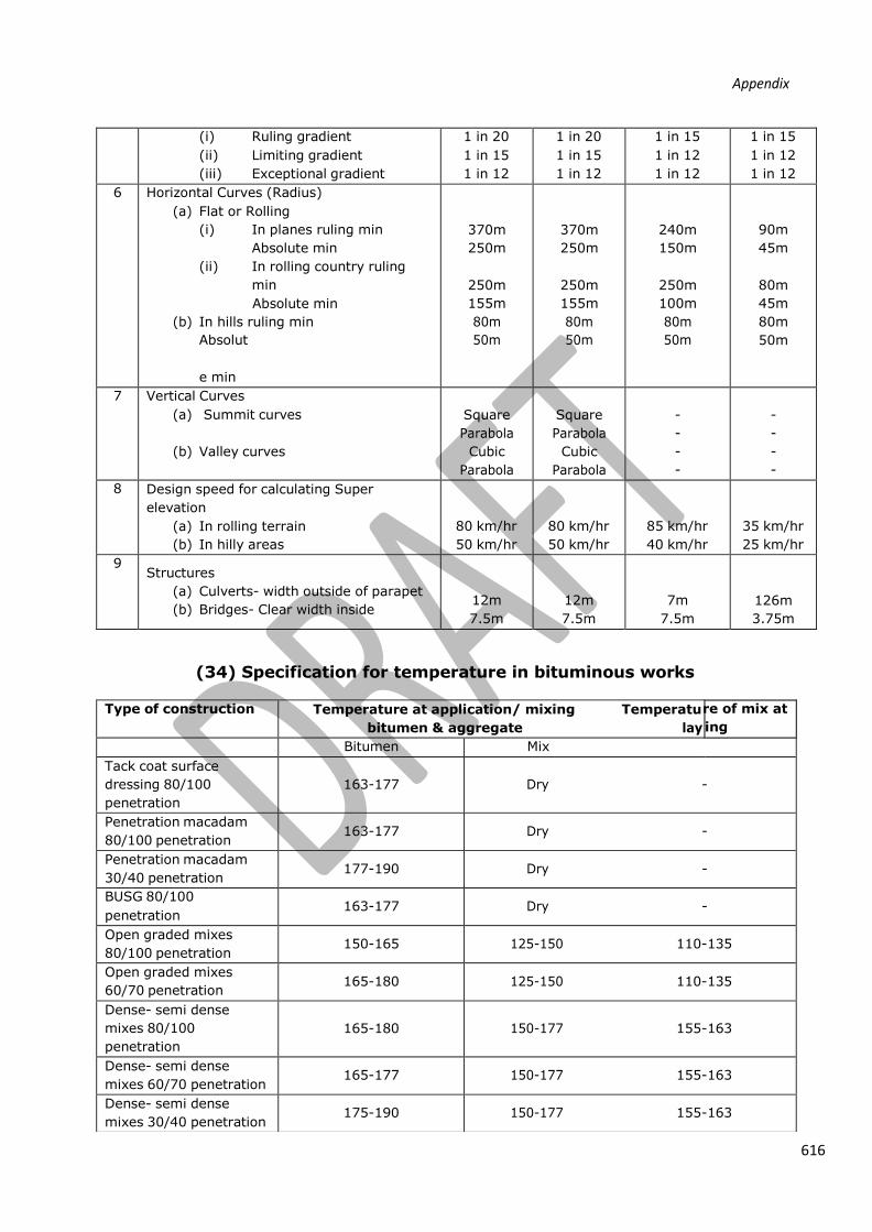
616
Appendix
(i) Ruling gradient
(ii) Limiting gradient
(iii) Exceptional gradient
1 in 20
1 in 15
1 in 12
1 in 20
1 in 15
1 in 12
1 in 15
1 in 12
1 in 12
1 in 15
1 in 12
1 in 12
6 Horizontal Curves (Radius)
(a) Flat or Rolling
(i) In planes ruling min
Absolute min
(ii) In rolling country ruling
min
Absolute min
(b) In hills ruling min
Absolut
e min
370m
250m
250m
155m
80m
50m
370m
250m
250m
155m
80m
50m
240m
150m
250m
100m
80m
50m
90m
45m
80m
45m
80m
50m
7 Vertical Curves
(a) Summit curves
(b) Valley curves
Square
Parabola
Cubic
Parabola
Square
Parabola
Cubic
Parabola
-
-
-
-
-
-
-
-
8 Design speed for calculating Super
elevation
(a) In rolling terrain
(b) In hilly areas
80 km/hr
50 km/hr
80 km/hr
50 km/hr
85 km/hr
40 km/hr
35 km/hr
25 km/hr
9 Structures
(a) Culverts- width outside of parapet
(b) Bridges- Clear width inside
12m
7.5m
12m
7.5m
7m
7.5m
126m
3.75m
(34) Specification for temperature in bituminous works
re of mix at
ing
Type of construction Temperature at application/ mixing Temperatu
bitumen & aggregate lay
Bitumen Mix Tack coat surface
dressing 80/100
penetration
163-177
Dry -
Penetration macadam
80/100 penetration 163-177 Dry -
Penetration macadam
30/40 penetration 177-190 Dry -
BUSG 80/100
penetration 163-177 Dry -
Open graded mixes
80/100 penetration 150-165 125-150 110-135
Open graded mixes
60/70 penetration 165-180 125-150 110-135
Dense- semi dense
mixes 80/100
penetration
165-180
150-177 155-163
Dense- semi dense
mixes 60/70 penetration 165-177 150-177 155-163
Dense- semi dense
mixes 30/40 penetration 175-190 150-177 155-163

Appendix
(35) Tentative Output of Road Machinery
Sl.No. Machine/ Tool Output
1 Scraper(motorised) towed 160 cum/day
2 Dozer 200 cum/day
3 Motor Grader 600 cum/day
4 Excavator 1 m3 capacity 400 cum/day
5 Three smooth wheeled road roller
5.1 Earth work 450 cum/day
5.2 Moorum/Gravel 450 cum/day
5.3 Pavement
1. WBM Stone base course 45 cum/day
2. WBM/ WMM wearing course 40 cum/day
3. DBM 40 cum/day
5.4 Surface Dressing
1. First Coat 2500 Sqm/ day
2. Second Coat 3500 Sqm/ day
5.5 Premix Carpet
1. 25 mm Thick 2000 Sqm/ day
2. 20 mm Thick 2000 Sqm/ day
6 Earthwork compaction by sheep foot
road roller 600 cum/day
7 Vibratory Road Roller earth-work
(Depends on layer thickness and type)
600 cum/day
8 Other Machinery
8.1 Mini-Hot Mix Plant 6-10 TPH 8 Ton/Hr
8.2 Hot Mix Plant 40-60 TPH 50 Ton/Hr
8.3 Paver Finisher 75-160 TPH 75 Ton/Hr
8.4 Bitumen Boiler 2000 Litr/hr
8.5 Water Tankers 10,000 litres
8.6 Bitumen Pressure Distributors 10,000 litres
8.7 Wet Mix Macadam Plant 60 TPH 50 Ton/Hr
8.8 Stone crusher less than 100 ton/ hr Depends on requirement

618
Appendix
8.9 Multistage Stone crusher more than
100ton/hr Depends on requirement
8.10 Concrete Batch mixing Plant upto 50
cum/Hr 40 cum/hr
8.11 Concrete Batching Mix more than 50
cum/Hr Depends on requirement
9 Haulage by trucks/Tippers
9.1 When lead = 2 km 8 Trips per day
9.2 When lead = 8 km 6 Trips per day
9.3 When Lead = 16 km 5 trips per day
9.4 When lead = 30 km 4 trips per day
(36) Floor- Area ratio (F.A.R)
Sl No.
Building use/ Occupancy
Max.
permissible
coverage
Max permissible
FAR (without
additional fee)
Max.
permissible FAR
(with additional
fee)
1 Residential A1 65 3 4
2 Spl. Residential A2 65 2.5 4
3 Educational B 35 2.5 3
4 Medical/ Hospital C 40 2 3
5 Assembly D 40 1.5 2.5
6 Office/ Business D 40 2 3
7 Mercantile/ Commercial F 65 2.5 4
8 Industrial G1 40 1.5 0
9 Small Industrial G2 60 2.5 3
10 Storage H 60 2.5 3
11 Hazardous I1 30 1 0
12 Hazardous I2 25 0.7 0
(37) Requirements of parts of buildings
1. Plinth
Main buildings- The plinth or any part of a building shall be so located with respect to the
surrounding ground level that adequate drainage of the site is assured. The height of plinth
shall not be less than 45cm from the surrounding ground level.
Interior courtyard- Every interior courtyard shall be raised atleast 15cm above the level of the
centre of the nearest street and shall be satisfactorily drained.
2. Habitable rooms
Residential, business & mercantile buildings- The height of all rooms for human habitation
shall not be less than 2.75m measured from the surface of the floor to the lowest point of the
ceiling.
Educational buildings- Ceiling height 3.6m for all regions; in cold regions, 3m
Industrial buildings- Ceiling height 3.6m, except when air conditioned, 3m
3. Bathrooms & Water closets
The height of the bathroom/ WC measured from the surface of the floor to the lowest point in
the ceiling shall not be less than 2m.

4. Ledge or Tand/ Loft
620
Appendix
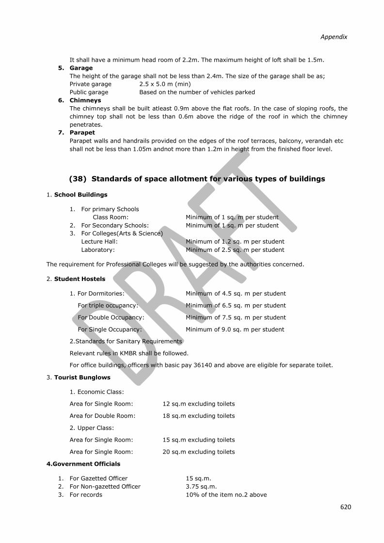
It shall have a minimum head room of 2.2m. The maximum height of loft shall be 1.5m.
5. Garage
The height of the garage shall not be less than 2.4m. The size of the garage shall be as;
Private garage 2.5 x 5.0 m (min)
Public garage Based on the number of vehicles parked
6. Chimneys
The chimneys shall be built atleast 0.9m above the flat roofs. In the case of sloping roofs, the
chimney top shall not be less than 0.6m above the ridge of the roof in which the chimney
penetrates.
7. Parapet
Parapet walls and handrails provided on the edges of the roof terraces, balcony, verandah etc
shall not be less than 1.05m andnot more than 1.2m in height from the finished floor level.
(38) Standards of space allotment for various types of buildings 1. School Buildings
1. For primary Schools
Class Room: Minimum of 1 sq. m per student
2. For Secondary Schools: Minimum of 1 sq. m per student
3. For Colleges(Arts & Science) Lecture Hall: Minimum of 1.2 sq. m per student
Laboratory: Minimum of 2.5 sq. m per student
The requirement for Professional Colleges will be suggested by the authorities concerned.
2. Student Hostels
1. For Dormitories: Minimum of 4.5 sq. m per student
For triple occupancy: Minimum of 6.5 sq. m per student
For Double Occupancy: Minimum of 7.5 sq. m per student
For Single Occupancy: Minimum of 9.0 sq. m per student
2. Standards for Sanitary Requirements
Relevant rules in KMBR shall be followed.
For office buildings, officers with basic pay 36140 and above are eligible for separate toilet.
3. Tourist Bunglows
1. Economic Class:
Area for Single Room: 12 sq.m excluding toilets
Area for Double Room: 18 sq.m excluding toilets
2. Upper Class:
Area for Single Room: 15 sq.m excluding toilets
Area for Single Room: 20 sq.m excluding toilets
4.Government Officials
1. For Gazetted Officer 15 sq.m.
2. For Non-gazetted Officer 3.75 sq.m.
3. For records 10% of the item no.2 above
Appendix
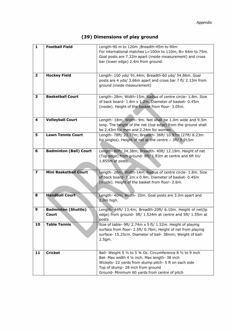
(39) Dimensions of play ground
1 Football Field Length-90 m to 120m ;Breadth-45m to 90m
For international matches L=100m to 110m; B= 64m to 75m.
Goal posts are 7.32m apart (inside measurement) and cross
bar (lower edge) 2.4m from ground.
2 Hockey Field Length- 100 yds/ 91.44m; Breadth-60 yds/ 54.86m. Goal
posts are 4 yds/ 3.66m apart and cross bar 7 ft/ 2.13m from
ground (inside measurement)
3 Basketball Court Length- 28m; Width-15m. Radius of centre circle- 1.8m. Size
of back board- 1.8m x 1.2m. Diameter of basket- 0.45m
(inside). Height of the basket from floor- 3.05m.
4 Volleyball Court Length- 18m; Width- 9m. Net shall be 1.0m wide and 9.5m
long. The height of the net (top edge) from the ground shall
be 2.43m for men and 2.24m for women.
5 Lawn Tennis Court Length- 78ft/ 23.77m; Breadth- 36ft/ 10.97m (27ft/ 8.23m
for singles). Height of net at the centre – 3ft/ 0.915m
6 Badminton (Ball) Court Length- 80ft/ 24.38m; Breadth- 40ft/ 12.19m. Height of net
(Top edge) from ground- 6ft/ 1.83m at centre and 6ft lin/
1.855m at posts.
7 Mini Basketball Court Length- 26m; Width-14m. Radius of centre circle- 1.8m. Size
of back board- 1.2m x 0.9m. Diameter of basket- 0.45m
(inside). Height of the basket from floor- 2.6m.
8 Handball Court Length- 40m; Width- 20m. Goal posts are 3.0m apart and
2.0m high.
9 Badminton (Shuttle)
Court
Length- 44ft/ 13.4m; Breadth-20ft/ 6.10m. Height of net(tp
edge) from ground- 5ft/ 1.524m at centre and 5ft/ 1.55m at
posts
10 Table Tennis Size of table- 9ft/ 2.74m x 5 ft/ 1.52m. Height of playing
surface from floor- 2.5ft/ 0.76m; Height of net from playing
surface- 15.25cm. Diameter of ball- 38mm; Weight of ball-
2.5gm.
11 Cricket Ball- Weight 5 ½ to 5 ¾ Oz. Circumference 8 ½ to 9 inch
Bat- Max width 4 ¼ inch. Max length- 38 inch
Wickets- 22 yards from stump pitch- 5 ft on each side
Top of stump- 28 inch from ground
Ground- Minimum 60 yards from centre of pitch
622
Appendix
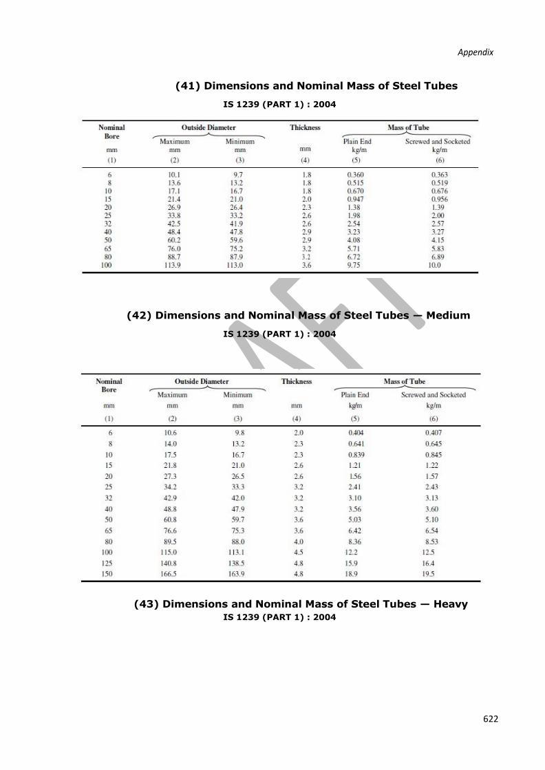
(41) Dimensions and Nominal Mass of Steel Tubes
IS 1239 (PART 1) : 2004
(42) Dimensions and Nominal Mass of Steel Tubes — Medium
IS 1239 (PART 1) : 2004
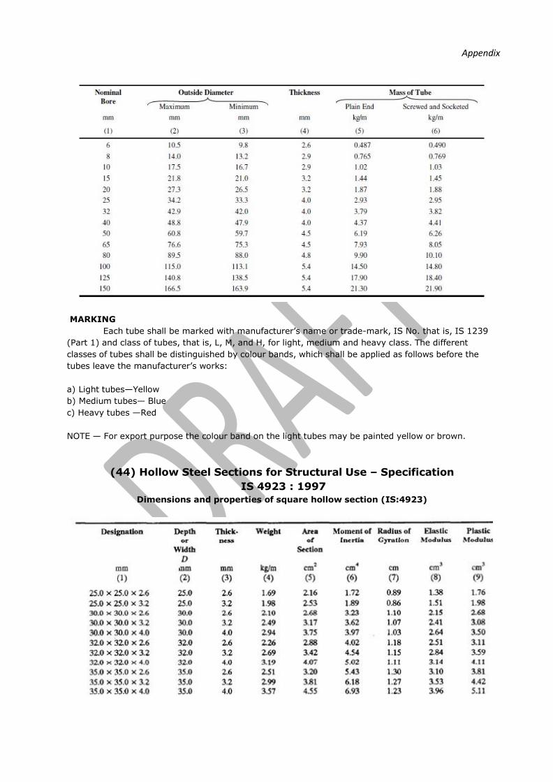
(43) Dimensions and Nominal Mass of Steel Tubes — Heavy
IS 1239 (PART 1) : 2004
Appendix
MARKING
Each tube shall be marked with manufacturer’s name or trade-mark, IS No. that is, IS 1239
(Part 1) and class of tubes, that is, L, M, and H, for light, medium and heavy class. The different
classes of tubes shall be distinguished by colour bands, which shall be applied as follows before the
tubes leave the manufacturer’s works:
a) Light tubes—Yellow
b) Medium tubes— Blue
c) Heavy tubes —Red
NOTE — For export purpose the colour band on the light tubes may be painted yellow or brown.
(44) Hollow Steel Sections for Structural Use – Specification
IS 4923 : 1997
Dimensions and properties of square hollow section (IS:4923)

624
Appendix

Appendix
(45) Dimensions and properties of Rectangular hollow steel sections (IS:4923)