Embed Size (px)
Citation preview

Component/ Fault Monitor Strategy Primary Malfunction Threshold Secondary Enable Time Frequency MILSystem Code Description Signal and Criteria Conditions Parameters Conditions Required of Checks Illum.
Catalyst Bank 1 P0420 oxygen storage of catalyst
normalized oxygen storage
<1 factor exhaust gas mass flow >35kg/h max. 18 sec. once per trip
1 trip
less than normalized oxygen storage
exhaust gas mass flow <150kg/h continuous
of a limit catalyst catalyst temp. model <700° C with: 0.4 sec
catalyst temp. model >480°C continuous
engine speed >960rpm or 4 sec cum
engine speed <2760rpmengine load (RLKTDMN) >18%engine load (RLKTDMX) <70.. .80%modeled catalyst temp. gradient <2.5° C / sec
exhaust gas mass flow gradient <8.33g/sec²
fuel system closed loop activetime after dew point exeeded at secondary O2 sensor *
> 40 sec.
ambient temperature >-48° Csecondary O2 sensor voltage > 0.55 Verror: fuel system trim rich or lean (P2177,P2178,P2187,P2188)
not set
short term fuel trim ( < max ) <1.25factorshort term fuel trim ( > min ) >0.75factorerror: critical misfire rate (P0300-P0306)
not set
error: cat. damaging misfire rate exceeded (P0300-P0306)
not set
MisfireEmission LevelMultiple Cylinder P0300 crankshaft speed
fluctuation cylinder 1 to cylinder 6
emissions relevant misfire rate
> 1,92% engine speed > 450rpm first Interval: 1000 revs.
continous 2 trips
Cylinder #1 P0301 engine speed < 6500rpm with: 0.4 sec
Cylinder #2 P0302 indicated torque (idle, no drive) > 5,47% remaining intervals:
4000 revs.
continous continuous
12 OBDG03 Engine DiagnosticsECM SECTION
1 OF 2 SECTIONS
ECM SECTION Page 1 of 74 1 OF 2 SECTIONS

Component/ Fault Monitor Strategy Primary Malfunction Threshold Secondary Enable Time Frequency MILSystem Code Description Signal and Criteria Conditions Parameters Conditions Required of Checks Illum.
Cylinder #3 P0303 indicated torque (drive) (MISALUN)
> 5,47 . . . 20,7%
or 4 sec cum
Cylinder #4 P0304 engine speed gradient (NGALUN)
<12800rpm/sec
Cylinder #5 P0305 volumetric efficiency gradient <768%/revCylinder #6 P0306 cylinder events after engine start > 6ignitions
engine coolant temperatureintake air temperature
> -30°C> -30°C
error: crankshaft sensor (P0335, P0336, P0338)
not set
error: ref.mark of crank sensor (P0016-P0019)
not set
Catalyst Damaging LevelMultiple Cylinder P0300 Catalyst damaging misfire
rate> 16,7 . . . 4,7% Includes all the above with the
following exceptions:First
Cylinder #1 P0301 (KFKSWFS; AHEKSB1) see Misfire supplemental data(h) (2.5.1)
First interval when engine coolant start temperature is
< 0 °C First Interval: 1000 revs
continous occurance:
Cylinder #2 P0302 First interval when engine coolant start temperature is
> 0 °C First Interval: 200 revs
continous immediate
Cylinder #3 P0303 MIL flashing
Cylinder #4 P0304 Remaining intervals
continous
Cylinder #5 P0305 200 revs SecondCylinder #6 P0306 occuranc
e:immediat
eMIL
flashingwith
constant
MILafterwar
ds
12 OBDG03 Engine DiagnosticsECM SECTION
1 OF 2 SECTIONS
ECM SECTION Page 2 of 74 1 OF 2 SECTIONS

Component/ Fault Monitor Strategy Primary Malfunction Threshold Secondary Enable Time Frequency MILSystem Code Description Signal and Criteria Conditions Parameters Conditions Required of Checks Illum.
Fuel evaporative system(monitor during engine run)canister ventilation valve (AAV)
P0446 monitoring of tank pressure while
tank pressure too low because
< -25 hPaengine start temperature (TMSTLDMN, TMSTDLDMX)
2 °C ... 38 °C approx. 10 sec
once per trip
2 trips
AAV is open and CPV is closed
canister vent. defective & closed
ambient temperature (TUMTLDU, TUMTLDO)
2 °C ... 38 °C
difference ambient temperature and engine start temperature < 15°C
canister purge valve (CPV)
P0496 monitoring of tank pressure while
final pressure too low because
< -0.6 hPa ambient pressure >= 680.00 hPa approx. 10 sec
once per trip
CPV and AAV are closed
CPV defective and open vehicle speed <= 1,86 mph
angle accelerator pedal 0 °P0497 monitoring of tank
pressure whilepurge control stuck closed > -0.2 hPa unfiltered tank pressure >= -40.00 hPa
CPV and AAV are closed
and unfiltered tank pressure <= 10.00 hPa
battery voltage >= 10.45 Vtank leak rough P0455 AAV is closed and CPV
is openvacuum pressure built up gradient too low
> 0.15 … 0.19 hPa/s
and battery voltage <= 18.00 V approx. 20 sec
once per trip
(KLTLDSFS05) fuel system status closed loopbecause of large tank leakage
> -13 hPa secondary air system * inactive
(for example: open gas filler cap)
tank fuel level (FTSDMN, FSTDMX)
11l ... 76l
error: fuel system trim rich or lean (P2177,P2178,P2187,P2188)
not set
multiplicative fuel trim adaption integrator deviation
< 0.015
for time 6 sec.lambda controller deviation < 0.03 or time since engine start exceeds threshold
> 400 sec
error: tank pressure sensor (P0450-P0453)
not set
error: engine speed sensor (P0335, P0336, P0338)
not set
12 OBDG03 Engine DiagnosticsECM SECTION
1 OF 2 SECTIONS
ECM SECTION Page 3 of 74 1 OF 2 SECTIONS

Component/ Fault Monitor Strategy Primary Malfunction Threshold Secondary Enable Time Frequency MILSystem Code Description Signal and Criteria Conditions Parameters Conditions Required of Checks Illum.
error: ambient temperature sensor (U0073)
not set
error: canister purge valve (P0496,P0497)
not set
error: engine coolant temperature sensor (P0116-P0119)
not set
error: canister ventilation valve (P0446)
not set
error: critical misfire rate (P0300-P0306)
not set
error: fuel level sensor (P0461-P0463, P2066-P2068)
not set
Fuel Evaporative System(monitor after ignition off)
P0442 Monitor fuel tank's pressure after engine stop and ignition off
Engine coolant temperature at start.
<= 42°C max. 4 trips once per trip
1 trip
tank leak smallest engine coolant temp. at start - intake air temp.
<= 15°C for each trip max. 2900s
Filter the normalized pressure from each trip
ambient air temperature >= 2°C continuous
with an EWMA filter. ambient air temperature <= 38°C after engine stop
Compare filtered result with threshold.
Filtered normalized pressure
> 0.5 engine has been running for a cal. min. time
>600sec and ignition off
> 0.4 if previous result
engine coolant temp. at engine stop
>60°C
detected a leak ambient pressure >= 680hPa
Pressure threshold for each trip
Absolute max. neg. pressure + Max. pos. pressure
> 1.20 … 4.00 hPa
driving distance (in current trip) covered
>= 4mi
(KFEONVPT) driving distance (for vehicle lifetime) covered
>= 12,27mi
For each trip following strategy:
the fuel tank's level isn't at its minimum
11l
Look for maximum positive pressure.
the fuel tank's level isn't at its maximum
76l
Abort if: battery's voltage >11V- max. pos. pressure >= Max. pos. pressure > 1.20 … 4.00
hPano refueling activity
12 OBDG03 Engine DiagnosticsECM SECTION
1 OF 2 SECTIONS
ECM SECTION Page 4 of 74 1 OF 2 SECTIONS

Component/ Fault Monitor Strategy Primary Malfunction Threshold Secondary Enable Time Frequency MILSystem Code Description Signal and Criteria Conditions Parameters Conditions Required of Checks Illum.
threshold. (KFEONVPT) error: intake air temperature (P0111-P0114)
not set
- max. pressure - current
max. pressure - current pressure
>= 0.05 hPa error: canister purge valve (P0496,P0497)
not set
pressure >= threshold 100s error: ambient pressure sensor (P2227-2229)
not set
for a specific time. error: vehicle speed sensor (P0501-P0503)
not set
- pressure stays in range
absolute pressure <= 0.69946 hPa error: engine coolant temperature sensor (P0116-P0119)
not set
near zero for 300s error: tank pressure sensor (P0450-P0453)
not set
a specific time. error: battery voltage not set- pressure <= pressure <= -0.75 hPa error: air mass flow sensor
(P0100-P0103)not set
threshold 25s error: canister ventilation valve (P0446)
not set
for a specific time error: tank leak rough (P0455) not set(vacuum build-up instead
of pressure build-up) - pressure-phase-time pressure phase time >= 2400.00 s
>= threshold. - diagnostic-time >= diagnostic time >= 2900.00 sthreshold
Look for absolut maximum negative pressure
Abort if: - max. neg. pressure <= Abs . max. neg. pressure > 1.20 … 4.00
hPathreshold (KFEONVPT)- diagnostic time >= diagnostic time >= 2900.00 sthreshold - current pressure - neg.
current pressure - neg. pressure
>= 0.05 hPa
pressure >= threshold 100s
for a specific time
12 OBDG03 Engine DiagnosticsECM SECTION
1 OF 2 SECTIONS
ECM SECTION Page 5 of 74 1 OF 2 SECTIONS

Component/ Fault Monitor Strategy Primary Malfunction Threshold Secondary Enable Time Frequency MILSystem Code Description Signal and Criteria Conditions Parameters Conditions Required of Checks Illum.
- pressure stays in absolute pressure <= 0.69946 hPa
ambient range for a 300sspecific time - canister vent valve re- no. canister vent valve
openings> 2
opened for a more than N times
because the pressure pressure 0.74951 hPa
exceeds a threshold
Secondary Air System
P0411 passive functional check
relative secondary air mass flow. Ratio from
< 0.45 catalyst heating * active max. 60s once per trip
2 trips
calculated secondary air mass by pressure
> 1.2 secondary air system * active
sensor signal and secondary air mass model
intake air temperature > 0 °C
intake air temperature < 80.3 °C Secondary Air Valve
P2440 Look for pressure pulsations
Top peak of pulsation > 30 hpa engine coolant temperature > 0 °C
stuck open check
Bottom peak of pulsation < -30 hPa engine coolant temperature < 120 °C
Average of absolute value of pulsations
> 10 hPa ambient pressure > 680 hPa.
error: ambient pressure sensor (P2227-2229)
not set
error: intake air temperature (P0111-P0114)
not set
error: engine coolant temperature sensor (P0116-P0119)
not set
error: secondary air pump (power stage) (P0418, P2244,P2245)
not set
error: battery voltage not setmass airflow > 6 kg/hmass airflow < 130 kg/hchange in air charge per working cycle
<= 7 %
12 OBDG03 Engine DiagnosticsECM SECTION
1 OF 2 SECTIONS
ECM SECTION Page 6 of 74 1 OF 2 SECTIONS
Component/ Fault Monitor Strategy Primary Malfunction Threshold Secondary Enable Time Frequency MILSystem Code Description Signal and Criteria Conditions Parameters Conditions Required of Checks Illum.
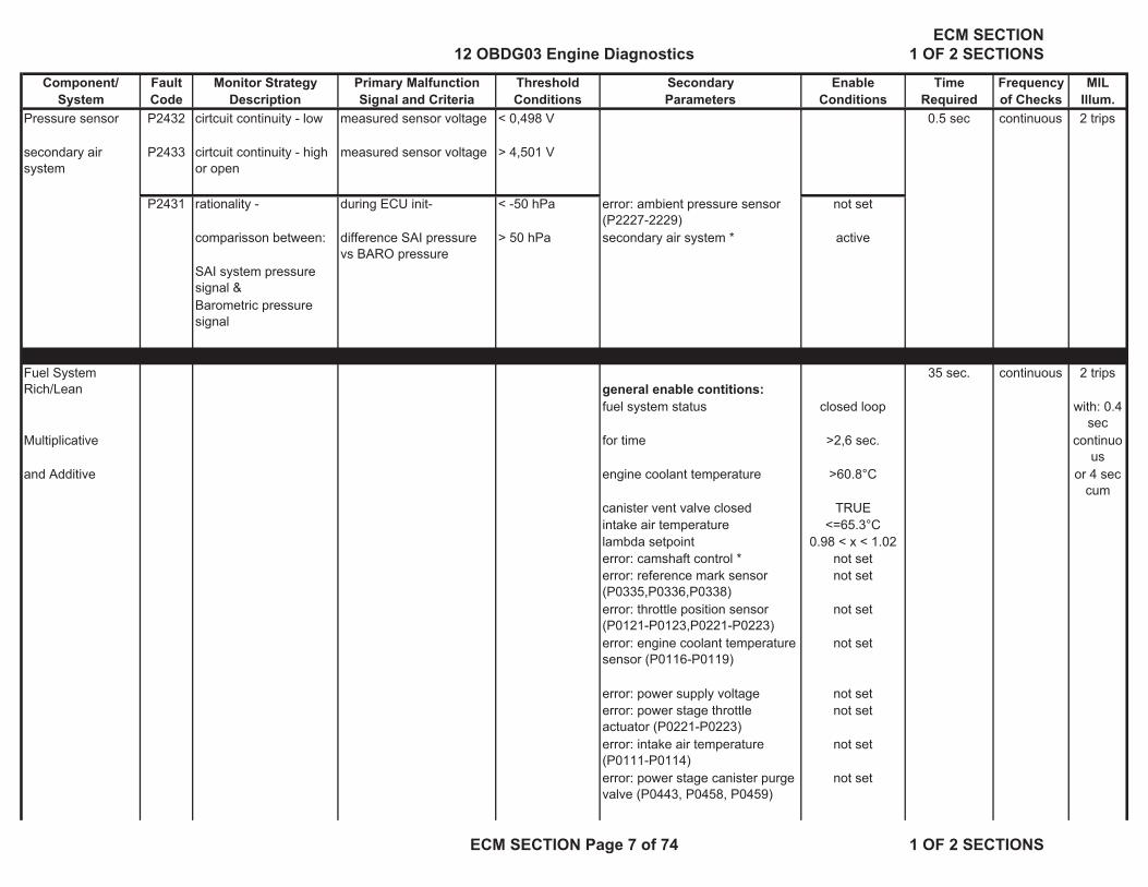
Pressure sensor P2432 cirtcuit continuity - low measured sensor voltage < 0,498 V 0.5 sec continuous 2 trips
secondary air system
P2433 cirtcuit continuity - high or open
measured sensor voltage > 4,501 V
P2431 rationality - during ECU init- < -50 hPa error: ambient pressure sensor (P2227-2229)
not set
comparisson between: difference SAI pressure vs BARO pressure
> 50 hPa secondary air system * active
SAI system pressure signal &Barometric pressure signal
Fuel System Rich/Lean general enable contitions:
35 sec. continuous 2 trips
fuel system status closed loop with: 0.4 sec
Multiplicative for time >2,6 sec. continuous
and Additive engine coolant temperature >60.8°C or 4 sec cum
canister vent valve closed TRUEintake air temperature <=65.3°Clambda setpoint 0.98 < x < 1.02error: camshaft control * not seterror: reference mark sensor (P0335,P0336,P0338)
not set
error: throttle position sensor (P0121-P0123,P0221-P0223)
not set
error: engine coolant temperature sensor (P0116-P0119)
not set
error: power supply voltage not seterror: power stage throttle actuator (P0221-P0223)
not set
error: intake air temperature (P0111-P0114)
not set
error: power stage canister purge valve (P0443, P0458, P0459)
not set
12 OBDG03 Engine DiagnosticsECM SECTION
1 OF 2 SECTIONS
ECM SECTION Page 7 of 74 1 OF 2 SECTIONS

Component/ Fault Monitor Strategy Primary Malfunction Threshold Secondary Enable Time Frequency MILSystem Code Description Signal and Criteria Conditions Parameters Conditions Required of Checks Illum.
error: multiple misfire (P0300-P0306)
not set
error: lambda sensor upstream catalyst (P0130-P0134)
not set
error: lambda sensor heating upstream catalyst (P0134,P0135)
not set
error: canister purge system * not setspecial enable contitions
P2177 fuel trim limits exceedes range multiplicative
delta lambda correction >1.175factor
indicated torque > 17% … 11%< 37% .. 46%
P2178 fuel trim limits exceedes range multiplicative
or delta lambda correction <0.825factor
engine speed
>= 1080 rpm
<= 3000rpmP2187 system too lean at idle delta fuel load correction >5.25%
indicated torque > 4.8%P2188 system too rich at idle or delta fuel load
correction<-5.25%
< 17.3% … 11%engine speed >= 520rpm
<= 960rpm
Diagnosis of Power Control Module
general enabling conditions 0.6 sec continuous 2 trips
battery voltage < 17.9 V> 10 V
locking request immobilizer not avtive
special enabling condition P0629 diagnosis short circuit
to battery voltagebackward powerstage voltage of
> 2.21 V fuel pump relay commanded "OFF"
TRUE
fuel pump diagnosis for a time 0.1 sec.and backward powerstage voltage of
>= 2.74 V
fuel pump diagnosis
12 OBDG03 Engine DiagnosticsECM SECTION
1 OF 2 SECTIONS
ECM SECTION Page 8 of 74 1 OF 2 SECTIONS
Component/ Fault Monitor Strategy Primary Malfunction Threshold Secondary Enable Time Frequency MILSystem Code Description Signal and Criteria Conditions Parameters Conditions Required of Checks Illum.
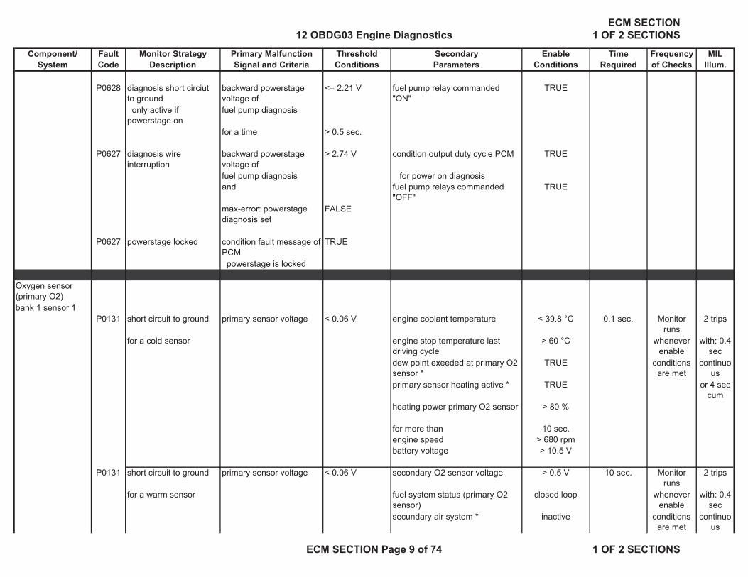
P0628 diagnosis short circiut to ground
backward powerstage voltage of
<= 2.21 V fuel pump relay commanded "ON"
TRUE
only active if powerstage on
fuel pump diagnosis
for a time > 0.5 sec.
P0627 diagnosis wire interruption
backward powerstage voltage of
> 2.74 V condition output duty cycle PCM TRUE
fuel pump diagnosis for power on diagnosis and fuel pump relays commanded
"OFF"TRUE
max-error: powerstage diagnosis set
FALSE
P0627 powerstage locked condition fault message of PCM
TRUE
powerstage is locked
Oxygen sensor (primary O2)bank 1 sensor 1
P0131 short circuit to ground primary sensor voltage < 0.06 V engine coolant temperature < 39.8 °C 0.1 sec. Monitor runs
2 trips
for a cold sensor engine stop temperature last driving cycle
> 60 °C whenever enable
with: 0.4 sec
dew point exeeded at primary O2 sensor *
TRUE conditions are met
continuous
primary sensor heating active * TRUE or 4 sec cum
heating power primary O2 sensor > 80 %
for more than 10 sec.engine speed > 680 rpmbattery voltage > 10.5 V
P0131 short circuit to ground primary sensor voltage < 0.06 V secondary O2 sensor voltage > 0.5 V 10 sec. Monitor runs
2 trips
for a warm sensor fuel system status (primary O2 sensor)
closed loop whenever enable
with: 0.4 sec
secundary air system * inactive conditions are met
continuous
12 OBDG03 Engine DiagnosticsECM SECTION
1 OF 2 SECTIONS
ECM SECTION Page 9 of 74 1 OF 2 SECTIONS

Component/ Fault Monitor Strategy Primary Malfunction Threshold Secondary Enable Time Frequency MILSystem Code Description Signal and Criteria Conditions Parameters Conditions Required of Checks Illum.
error: secondary air system (P0411,P0418,P2244,P2245,P2431-P2433)
not set or 4 sec cum
Fuel evaporative system monitoring (during engine run)
inactive
air passed at primary O2 sensor 2200g
dew point exeeded at primary O2 sensor *
TRUE
primary sensor heating active * TRUE
heating power primary O2 sensor > 80 %
for more than 10 sec.engine speed > 680 rpmbattery voltage > 10.5 V
bank 1 sensor 1 P0132 short circuit to battery voltage
primary O2 sensor voltage
>1.08V dew point exeeded at primary O2 sensor *
TRUE 5 sec. Monitor runs
2 trips
primary sensor heating active * TRUE whenever enable
with: 0.4 sec
heating power primary O2 sensor > 80 % conditions are met
continuous
for more than 10 sec. or 4 sec cum
desired A/F ratio > 0.995engine speed > 680 rpmbattery voltage > 10.5 V
bank 1 sensor 1 P0134 open circuit signal or ground line
when modelled exhaust gas temperature
battery voltage > 10.5 V 9 sec. Monitor runs
2 trips
primary O2 sensor at primary O2 sensor < 800 °C dew point exeeded at primary O2 sensor *
TRUE whenever enable
with: 0.4 sec
primary O2 sensor voltage in a range
0.4 … 0.6 V for more than 30 sec. conditions are met
continuous
(USDBO, USREF)
air passed at primary O2 sensor 2200g or 4 sec cum
for more than 10 sec.when modelled exhaust gas temperature
engine running > 680 rpm
12 OBDG03 Engine DiagnosticsECM SECTION
1 OF 2 SECTIONS
ECM SECTION Page 10 of 74 1 OF 2 SECTIONS

Component/ Fault Monitor Strategy Primary Malfunction Threshold Secondary Enable Time Frequency MILSystem Code Description Signal and Criteria Conditions Parameters Conditions Required of Checks Illum.
at primary O2 sensor > 800 °Cprimary O2 sensor voltage in a range
0.4 … 0.55 V(UBDBO,USREFHOT)
bank 1 sensor 1 P0134 open circuit signal or ground line
internal resistance of the 0.1 sec. Monitor runs
2 trips
primary O2 sensor primary O2 sensor > 20.000 Ohms battery voltage > 10.5 V whenever enable
with: 0.4 sec
dew point exeeded at primary O2 sensor *
TRUE conditions are met
continuous
for more than 30 sec. or 4 sec cum
air passed at primary O2 sensor 2200g
for more than 10 sec.engine running > 680 rpmmodelled exhaust gas temperature
> 600 °C
bank 1 sensor 1 P0130 heater coupling to the signal
primary O2 sensor voltage in range of
0.06 … 0.4 V battery voltage > 10.5 V 10 sec. Monitor runs
2 trips
primary O2 sensor (USMIN, USREMH) dew point exeeded at primary O2 sensor *
TRUE whenever enable
with: 0.4 sec
for more than 30 sec. conditions are met
continuous
air passed at primary O2 sensor 2200g or 4 sec cum
for more than 10 sec.engine running > 680 rpmfuel system status (primary O2 sensor)
closed loop
secundary air system * inactiveerror: secondary air system (P0411,P0418,P2244,P2245,P2431-P2433)
not set
Fuel evaporative system monitoring (during engine run)
inactive
secondary O2 sensor voltage > 0.5 Vair passed at primary O2 sensor 2200g
12 OBDG03 Engine DiagnosticsECM SECTION
1 OF 2 SECTIONS
ECM SECTION Page 11 of 74 1 OF 2 SECTIONS

Component/ Fault Monitor Strategy Primary Malfunction Threshold Secondary Enable Time Frequency MILSystem Code Description Signal and Criteria Conditions Parameters Conditions Required of Checks Illum.
P0130 heater coupling to the signal
primary O2 sensor voltage in range of
0.6 … 1.08 V battery voltage > 10.5 V 10 sec. Monitor runs
2 trips
primary O2 sensor (USREFHKLT, USMAX) dew point exeeded at primary O2 sensor *
TRUE whenever enable
with: 0.4 sec
for more than 30 sec. conditions are met
continuous
air passed at primary O2 sensor 2200g or 4 sec cum
for more than 10 sec.engine running > 680 rpmfuel system status (primary O2 sensor)
closed loop
secondary O2 sensor voltage < 0.1 VP0130 heater coupling to the
signal primary O2 sensor voltage
> 2.0 V dew point exeeded at primary O2 sensor *
TRUE 25 sec. Monitor runs
2 trips
primary O2 sensor within time after heater turn on
<0.04sec for more than 10 sec. whenever enable
with: 0.4 sec
for occurrences > 4 heating power primary O2 sensor > 80 % conditions are met
continuous
out of heater turn ons = 6 for more than 10 sec. or 4 sec cum
engine running > 680 rpmbattery voltage > 10.5 V
Oxgen sensor (primary O2)
P0133 dynamic response time of lambda period fuel system status (primary O2 sensor)
closed loop 10 lambda period
Monitor runs
2 trips
bank 1 sensor 1 slow or low amplitude corrected and weighted over
lambda controller 0.95 - 1.05 measurement
s
whenever enable
with: 0.4 sec
engine speed and load > 3 sec. engine speed in a range of 1000 … 3000 rpm
conditions are met
continuous
engine load in a range of 18 … 79.5 % or 4 sec cum
modelled exhaust gas temperature
> 300 °C
purge not longer active than 4 sec.secondary air system * inactive
error: fuel system trim rich or lean (P2177,P2178,P2187,P2188) not set
12 OBDG03 Engine DiagnosticsECM SECTION
1 OF 2 SECTIONS
ECM SECTION Page 12 of 74 1 OF 2 SECTIONS

Component/ Fault Monitor Strategy Primary Malfunction Threshold Secondary Enable Time Frequency MILSystem Code Description Signal and Criteria Conditions Parameters Conditions Required of Checks Illum.
Fuel evaporative system monitoring (during engine run)
inactive
Adaption of purge mass < 25 error: camshaft system * not set
Oxgen sensor (primary O2)
P2097 offset check enrichment adaption value fuel system status (secondary O2 sensor)
closed loop 60 sec. Monitor runs
2 trips
bank 1 sensor 1 closed loop secondary lambda control
> 0.79 sec. secondary air system * inactive whenever enable
with: 0.4 sec
after an acummulated monitoring time of
> 60 sec.error: fuel system trim rich or lean (P2177,P2178,P2187,P2188) not set
conditions are met
continuous
Fuel evaporative system monitoring (during engine run)
inactive or 4 sec cum
Adaption of purge mass < 25 error: camshaft system * not set
P2096 offset check enleanment
adaption value fuel system status (secondary O2 sensor)
closed loop
closed loop secondary lambda control
< - 0.79 sec. secondary air system * inactive
after an acummulated monitoring time of
> 60 sec.error: fuel system trim rich or lean (P2177,P2178,P2187,P2188) not setFuel evaporative system monitoring (during engine run)
inactive
Adaption of purge mass < 25 error: camshaft system * not set
Oxygen Sensor Heatingheater performance (primary O2)bank 1 sensor 1 (primary)
P0135 primary O2 sensor measured primary O2 sensor internal
battery voltage >10.5V 6 sec continuous 2 trips
internal resistance resistance battery voltage <18V with: 0.4 sec
12 OBDG03 Engine DiagnosticsECM SECTION
1 OF 2 SECTIONS
ECM SECTION Page 13 of 74 1 OF 2 SECTIONS
Component/ Fault Monitor Strategy Primary Malfunction Threshold Secondary Enable Time Frequency MILSystem Code Description Signal and Criteria Conditions Parameters Conditions Required of Checks Illum.
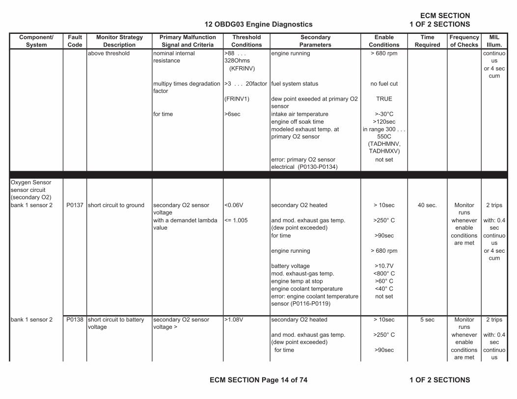
above threshold nominal internal resistance
>88 . . . 328Ohms
engine running > 680 rpm continuous
(KFRINV) or 4 sec cum
multipy times degradation factor
>3 . . . 20factor fuel system status no fuel cut
(FRINV1) dew point exeeded at primary O2 sensor
TRUE
for time >6sec intake air temperature >-30°Cengine off soak time >120secmodeled exhaust temp. at primary O2 sensor
in range 300 . . . 550C
(TADHMNV, TADHMXV)
error: primary O2 sensor electrical (P0130-P0134)
not set
Oxygen Sensorsensor circuit (secondary O2)bank 1 sensor 2 P0137 short circuit to ground secondary O2 sensor
voltage<0.06V secondary O2 heated > 10sec 40 sec. Monitor
runs 2 trips
with a demandet lambda value
<= 1.005 and mod. exhaust gas temp. (dew point exceeded)
>250° C whenever enable
with: 0.4 sec
for time >90sec conditions are met
continuous
engine running > 680 rpm or 4 sec cum
battery voltage >10.7Vmod. exhaust-gas temp. <800° Cengine temp at stop >60° Cengine coolant temperature <40° Cerror: engine coolant temperature sensor (P0116-P0119)
not set
bank 1 sensor 2 P0138 short circuit to battery voltage
secondary O2 sensor voltage >
>1.08V secondary O2 heated > 10sec 5 sec Monitor runs
2 trips
and mod. exhaust gas temp. (dew point exceeded)
>250° C whenever enable
with: 0.4 sec
for time >90sec conditions are met
continuous
12 OBDG03 Engine DiagnosticsECM SECTION
1 OF 2 SECTIONS
ECM SECTION Page 14 of 74 1 OF 2 SECTIONS

Component/ Fault Monitor Strategy Primary Malfunction Threshold Secondary Enable Time Frequency MILSystem Code Description Signal and Criteria Conditions Parameters Conditions Required of Checks Illum.
engine running > 680 rpm or 4 sec cum
battery voltage >10.7Vmod. exhaust-gas temp. <800° C
bank 1 sensor 2 P0140 sensor line disconnection
secondary O2 sensor voltage
>0.401V secondary O2 heated > 10sec max 150 sec Monitor runs
2 trips
and secondary O2 sensor voltage
<0.499V and mod. exhaust gas temp. (dew point exceeded)
>250° C whenever enable
with: 0.4 sec
for time >90sec conditions are met
continuous
orengine running > 680 rpm or 4 sec
cumsecondary O2 sensor internal resistance
>40000Ohm battery voltage >10.7V
when modeled exhaust gas temperature
>600° C mod. exhaust-gas temp. <800° C
bank 1 sensor 2 P2232 sensor line short circuit secondary O2 sensor > 2 V dew point exeeded at primary O2 sensor *
TRUE 10 sec Monitor runs
2 trips
to heater output line within time after heater turn on
<0.04sec for more than 20 sec. whenever enable
with: 0.4 sec
for occurrences >4count heating power primary O2 sensor > 50 % conditions are met
continuous
out of heater turn offs =6count for more than 20 sec. or 4 sec cum
engine running > 680 rpmbattery voltage > 10.5 V
Oxygen Sensor Heating
P0141 secondary O2 sensor measured secondary O2 sensor internal
battery voltage >10.7V 6 sec Monitor runs
2 trips
heater performance (secondary O2)
internal resistance resistance battery voltage <18V whenever enable
with: 0.4 sec
bank 1 sensor 2 (secondary)
above threshold nominal internal resistance
>120 . . . 560Ohms
engine running > 680 rpm conditions are met
continuous
(KFRINH) fuel system status no fuel cut or 4 sec cum
multipy times degradation factor
>3 . . . 30factor dew point exeeded at secondary O2 sensor *
TRUE
(FRINH1) intake air temperature >-30°Cfor time >6sec engine off soak time >150sec
12 OBDG03 Engine DiagnosticsECM SECTION
1 OF 2 SECTIONS
ECM SECTION Page 15 of 74 1 OF 2 SECTIONS

Component/ Fault Monitor Strategy Primary Malfunction Threshold Secondary Enable Time Frequency MILSystem Code Description Signal and Criteria Conditions Parameters Conditions Required of Checks Illum.
modeled exhaust temp. 350 . . . 550C (TADHMNH, TADHMXH)
at secondary O2 sensorerror: secondary O2 sensor electrical (P0137,P0138,P0140,P2232)
not set
sensor response (secondary O2)bank 1 sensor 2 P2270 oscillation check low secondary O2 sensor
voltage>0.602 . . . 0.621V
dew point exeeded at secondary O2 sensor *
TRUE max. Monitor runs
2 trips
for time > 0.2 sec for time >10sec 600 sec whenever enable
with: 0.4 sec
then fuel system status (secondary O2 sensor)
closed loop conditions are met
continuous
ramping in enrichment by= 0.15 lambda
all injectors activated > 0.8 ms or 4 sec cum
at gradient 0.0488 l / sec engine air flow (intrusive test) >5,56 g/secfor time (after enrichment limit reached)
>7 sec
and engine air flow
<41,6 g/sec for time >3secengine air flow (passive monitor)
>7,78 g/secerror: secondary O2 sensor electrical (P0137,P0138,P0140,P2232)
not set
lambda controller 0.92 … 1.07engine running > 680 rpmbattery voltage >10.7V
bank 1 sensor 2 P2271 oscillation check high secondary O2 sensor voltage
>0.602 . . . 0.621V
dew point exeeded at secondary O2 sensor *
TRUE max. Monitor runs
2 trips
for time > 0.2 sec for time >10sec 600 sec whenever enable
with: 0.4 sec
thenfuel system status (secondary O2 sensor)
closed loop conditions are met
continuous
ramping in enleanment by =0.10lambda
all injectors activated > 0.8 ms or 4 sec cum
at gradient 0.0488 l / sec engine air flow (intrusive test) >5,56 g/secfor time (after enleanment limit reached)
>7 sec
and engine air flow
<41,6 g/sec
12 OBDG03 Engine DiagnosticsECM SECTION
1 OF 2 SECTIONS
ECM SECTION Page 16 of 74 1 OF 2 SECTIONS
Component/ Fault Monitor Strategy Primary Malfunction Threshold Secondary Enable Time Frequency MILSystem Code Description Signal and Criteria Conditions Parameters Conditions Required of Checks Illum.
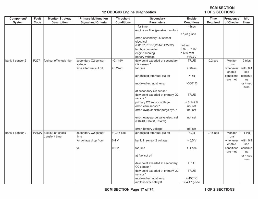
for time >3secengine air flow (passive monitor)
>7,78 g/secerror: secondary O2 sensor electrical (P0137,P0138,P0140,P2232) not setlambda controller 0.92 … 1.07engine running > 680 rpmbattery voltage >10.7V
bank 1 sensor 2 P2271 fuel cut off check high secondary O2 sensor voltage
>0.149V dew point exeeded at secondary O2 sensor *
TRUE 0.2 sec Monitor runs
2 trips
time after fuel cut off >6,2sec for time >30sec whenever enable
with: 0.4 sec
air passed after fuel cut off >15g conditions are met
continuous
modeled exhaust temp >350° C or 4 sec cum
at secondary O2 sensordew point exeeded at primary O2 sensor *
TRUE
primary O2 sensor voltage < 0.149 Verror: cam sensor * not seterror: evap canister purge sys. * not set
error: evap purge valve electrical (P0443, P0458, P0459)
not set
error: battery voltage not setbank 1 sensor 2 P013A fuel cut off check
transient timesecondary O2 sensor time
> 0.15 sec air passed after fuel cut off < 3 g 0.15 sec Monitor runs
1 trip
for voltage drop from 0.4 V bank 1 sensor 2 voltage > 0,5 V whenever enable
with: 0.4 sec
to 0.2 V for time > 1 sec conditions are met
continuous
at fuel cut off or 4 sec cum
dew point exeeded at secondary O2 sensor *
TRUE
dew point exeeded at primary O2 sensor *
TRUE
modeled exhaust temp > 450° Cair flow over catalyst > 4.17 g/sec
12 OBDG03 Engine DiagnosticsECM SECTION
1 OF 2 SECTIONS
ECM SECTION Page 17 of 74 1 OF 2 SECTIONS

Component/ Fault Monitor Strategy Primary Malfunction Threshold Secondary Enable Time Frequency MILSystem Code Description Signal and Criteria Conditions Parameters Conditions Required of Checks Illum.
engine speedin range 1100 - 3300 rpm
engine loadin range 10 - 30 %battery voltage > 11,0V
bank 1 sensor 2 P013E fuel cut off check response time
secondary O2 sensor voltage
> 0.152 V air passed after fuel cut off < 3 g 5 sec Monitor runs
1 trip
time after fuel cut off > 5 sec. bank 1 sensor 2 voltage > 0,5 V whenever enable
with: 0.4 sec
for time > 1 sec conditions are met
continuous
at fuel cut off or 4 sec cum
dew point exeeded at secondary O2 sensor *
TRUE
dew point exeeded at primary O2 sensor *
TRUE
modeled exhaust temp > 450° Cair flow over catalyst > 4.17 g/secengine speedin range 1100 - 3300 rpm
engine loadin range 10 - 30 %battery voltage > 11,0V
Camshaft Control
System - Locking Pin
2 trips
Bank 1 Intake P0011 rationality high average of actual angle measurements
> +/- 10degrees engine speed >560rpm 10 sec 0.01 sec with: 0.4 sec
Bank 2 Intake P0021 versus locked position angle
engine run time < 1 sec. continuous
Bank 1 Exhaust P0014 camshaft control circuit test complete or 4 sec cum
Bank 2 Exhaust P0024 error: camshaft control circuit * not set
12 OBDG03 Engine DiagnosticsECM SECTION
1 OF 2 SECTIONS
ECM SECTION Page 18 of 74 1 OF 2 SECTIONS

Component/ Fault Monitor Strategy Primary Malfunction Threshold Secondary Enable Time Frequency MILSystem Code Description Signal and Criteria Conditions Parameters Conditions Required of Checks Illum.
System - Control rationality low / high difference to start test (filtered actual
> 6 . . . 11 degrees
engine speed >560rpm approx. 0.01 sec 2 trips
Bank 1 Intake P000A angle versus filtered desired angle)
(KFDWNWDMXE)
engine run time > 1sec20 … 80 sec
continuous with: 0.4 sec
Bank 2 Intake P000C (desired must remain above value
camshaft control circuit test completedepending on drive pattern
continuous
Bank 1 Exhaust P000B to test to complete the evaluation)
error: camshaft control circuit * not set or 4 sec cum
Bank 2 Exhaust P000D filtered actual angle remains
< coolant temperature < 143° C
filtered desired angle from test start
coolant temperature >-48° C
within time (KFTDDNWNPA)
= 1.5 … 2 sec (exhaust)
engine oil temperature < 180° C
(detects 5 sec slow [time constant])
= 1.2 … 2 sec (intake)
engine oil temperature >-48° C
(KFTDDNWNPE) cam-crank alignment adaptation complete
for multiple activation occurrences
>7 counts (exhaust)
catalyst heating * inactive
(decrements upon activations where
>8 counts (intake)
no difference is seen between desiredand actual)difference (filtered actual angle max
>2degrees exh 1.8degrees in
versus actual at test start)
( to detect slow response versus stuck cam if above this limit )at time =3sec(overlaps with time to detect above)
(passes after multiple good activations
12 OBDG03 Engine DiagnosticsECM SECTION
1 OF 2 SECTIONS
ECM SECTION Page 19 of 74 1 OF 2 SECTIONS
Component/ Fault Monitor Strategy Primary Malfunction Threshold Secondary Enable Time Frequency MILSystem Code Description Signal and Criteria Conditions Parameters Conditions Required of Checks Illum.
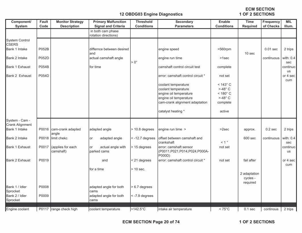
in both cam phase rotation directions)
System Control CSERSBank 1 Intake P052B differnce between desired
and engine speed >560rpm
10 sec0.01 sec 2 trips
Bank 2 Intake P052D actual camshaft angle> 0°
engine run time >1sec continuous with: 0.4 sec
Bank 1 Exhaust P054B for time camshaft control circuit test complete continuous
Bank 2 Exhaust P054D error: camshaft control circuit * not set or 4 sec cum
coolant temperature < 143° Ccoolant temperature >-48° Cengine oil temperature < 180° Cengine oil temperature >-48° Ccam-crank alignment adaptation complete
catalyst heating * active
System - Cam - Crank AlignmentBank 1 Intake P0016 cam-crank adapted
angleadapted angle > 10.8 degrees engine run time > >2sec approx. 0.2 sec 2 trips
Bank 2 Intake P0018 limit chekc or adapted angle < -12.7 degrees offset between camshaft and crankshaft < 1 °
600 sec continuous with: 0.4 sec
Bank 1 Exhaust P0017 (applies for each camshaft)
or actual angle with parked cams
> 15 degrees error: camshaft sensor (P0011,P021,P014,P024,P000A-P000D)
not set continuous
Bank 2 Exhaust P0019 and < 21 degrees error: camshaft control circuit * not set fail after or 4 sec cum
for a time > 10 sec.2 adaptation
cycles - required
Bank 1 / Idler Sprocket
P0008 adapted angle for both cams
> 6.7 degrees
Bank 2 / Idler Sprocket
P0009 adapted angle for both cams
< -7.9 degrees
Engine coolant P0117 range check high coolant temperature >142.5°C intake air temperature < 75°C 0.1 sec continous 2 trips
12 OBDG03 Engine DiagnosticsECM SECTION
1 OF 2 SECTIONS
ECM SECTION Page 20 of 74 1 OF 2 SECTIONS

Component/ Fault Monitor Strategy Primary Malfunction Threshold Secondary Enable Time Frequency MILSystem Code Description Signal and Criteria Conditions Parameters Conditions Required of Checks Illum.
temperature sensor difference between intake air temp and intake air temp. at engine shut down last driving cycle
< 20…9°C with: 0.4 sec
continuous
P0118 range check low coolant temperature <-38.3° C error: engine coolant temperature sensor (P0116-P0119)
not set or 4 sec cum
or time after engine start >=60sec
P0116 plausibility check (low side check)
calculated coolant temperature model
error: engine coolant temperature sensor (P0116-P0119)
not set 3 sec. once per trip
2 trips
minus measured temperature
>9.8° C measured coolant temperature <93.8° C with: 0.4 sec
engine speed >1000rpm continuous
integrated air mass >1500g or 4 sec cum
plausibility check (high side check)
measured temperature >9.8°C error: engine speed sensor (P0335, P0336, P0338)
not set
minus calculated coolant temperature model
error: air mass flow sensor (P0100-P0103)
not set
error: engine coolant temperature sensor (P0116-P0119)
not set
P0119 intermittent ( discontinuity )
delta coolant temperature < -10°C ignition =ON 0,03 sec. continuous 2 trips
orwith: 0.4
secdelta coolant temperature > 10°C continuo
us(between A/D read sample count offset)
=3count or 4 sec cum
P050C difference from intake air
filtered difference time after engine start >= 5 sec 0.1 sec. continuous 1 trip
temperature after soaking
( ECT at key on - IAT at key on )
>10°C previous accumulated air mass >4000g with: 0.4 sec
previous engine run time >500sec continuous
12 OBDG03 Engine DiagnosticsECM SECTION
1 OF 2 SECTIONS
ECM SECTION Page 21 of 74 1 OF 2 SECTIONS

Component/ Fault Monitor Strategy Primary Malfunction Threshold Secondary Enable Time Frequency MILSystem Code Description Signal and Criteria Conditions Parameters Conditions Required of Checks Illum.
orECT at shut down >84.75° C or 4 sec
cum
filtered differencecoolant temp. calculated out of model
<=50.3°C
( ECT at key on - IAT at key on )
<-10° C engine off time >21600sec
error: intake air temperature (P0111-P0114)
not set
error: range check coolant temperature sensor (P0117,P0118)
not set
Block Heater not detected
Engine Coolant P0128 Coolant Temperature Below
calculated coolant temp model
>5.3° C debouncing time >10 sec approx. once per trip
2 trips
Thermostat Monitoring
Thermostat Regulating minus measured coolant temperature
error: coolant temperature sensor (P0116-P0119,P050C)
not set 900 sec with: 0.4 sec
Temperature (plausibility check)
error: vehicle speed sensor (P0501-P0503)
not set continuous
model calculation limit 82°C est. ambient temperature > -8.3°C or 4 sec cum
est. ambient temperature <50°Cvehicle speed >=3.125mph
Thermostat regulating temperature: 82°C
engine speed >960rpm
( All critical OBD and coolant temperature at start < 51.0°C emission functions are enabled
integrated air mass flow >3458g
above 64°C. )
time after start to run the model (depending on engine coolant temp at start)
>= 22…16 sec (TWADTHMS)
Engine coolant overtemperature
P1258 coolant temperature > 132.8 °C error: engine coolant temp (P0116-P0119)
not set 1 sec. continuous 1 trip
Protection mode for a time > 1 sec. engine speed > 80 rpmfor a time > 30 sec.
12 OBDG03 Engine DiagnosticsECM SECTION
1 OF 2 SECTIONS
ECM SECTION Page 22 of 74 1 OF 2 SECTIONS

Component/ Fault Monitor Strategy Primary Malfunction Threshold Secondary Enable Time Frequency MILSystem Code Description Signal and Criteria Conditions Parameters Conditions Required of Checks Illum.
Intake air temperature
P0111 response check difference: max intake air temperature -
DRIVE PERIOD - COUNT 5 x 9 sec. Monitor runs
2 trips
sensor min intake air temperature >1,5° C EACH WITH: whenever enable
with: 0.4 sec
vehicle speed >=24,8mph conditions are met
continuous
mass flow <250g / sec or 4 sec cum
mass flow >15,6 g/seccoolant temperature at start <=120° Cno fuel shut-off ANDIDLE PERIOD - COUNT 5 x 11 sec.vehicle speed <=1.55mphcoolant temperature at start <=120° Ccoolant temperature >75° Cintegrated air mass increases (KLTFA1ML)
> 4002 . . . 15019 g
P0111 Difference from coolant temperature sensor
difference: intake air temperature - engine
>+35,3°C engine temperaure at start <35,3°C 300 sec. after start
once per trip
2 trips
coolant temperature or coolcant temperature decrease since
(block heater delay)
with: 0.4 sec
<-20,3°C engine stall > 39,8°C continuous
minimum coolant temperature or 4 sec cum
at engine stall last trip >80°C
P0112 range check lowintake air temperature
>124,9° C time after start > 15sec 0.1 sec. once per trip
2 trips
P0113 range check high intake air temperature <-34,9° C then time in idle >3sec with: 0.4 sec
and intake air temperature <-35.3° C continuous
then | IAT change | (abs value) <=2.3° C or 4 sec cum
whileintegrated air mass increases >=0g
12 OBDG03 Engine DiagnosticsECM SECTION
1 OF 2 SECTIONS
ECM SECTION Page 23 of 74 1 OF 2 SECTIONS
Component/ Fault Monitor Strategy Primary Malfunction Threshold Secondary Enable Time Frequency MILSystem Code Description Signal and Criteria Conditions Parameters Conditions Required of Checks Illum.
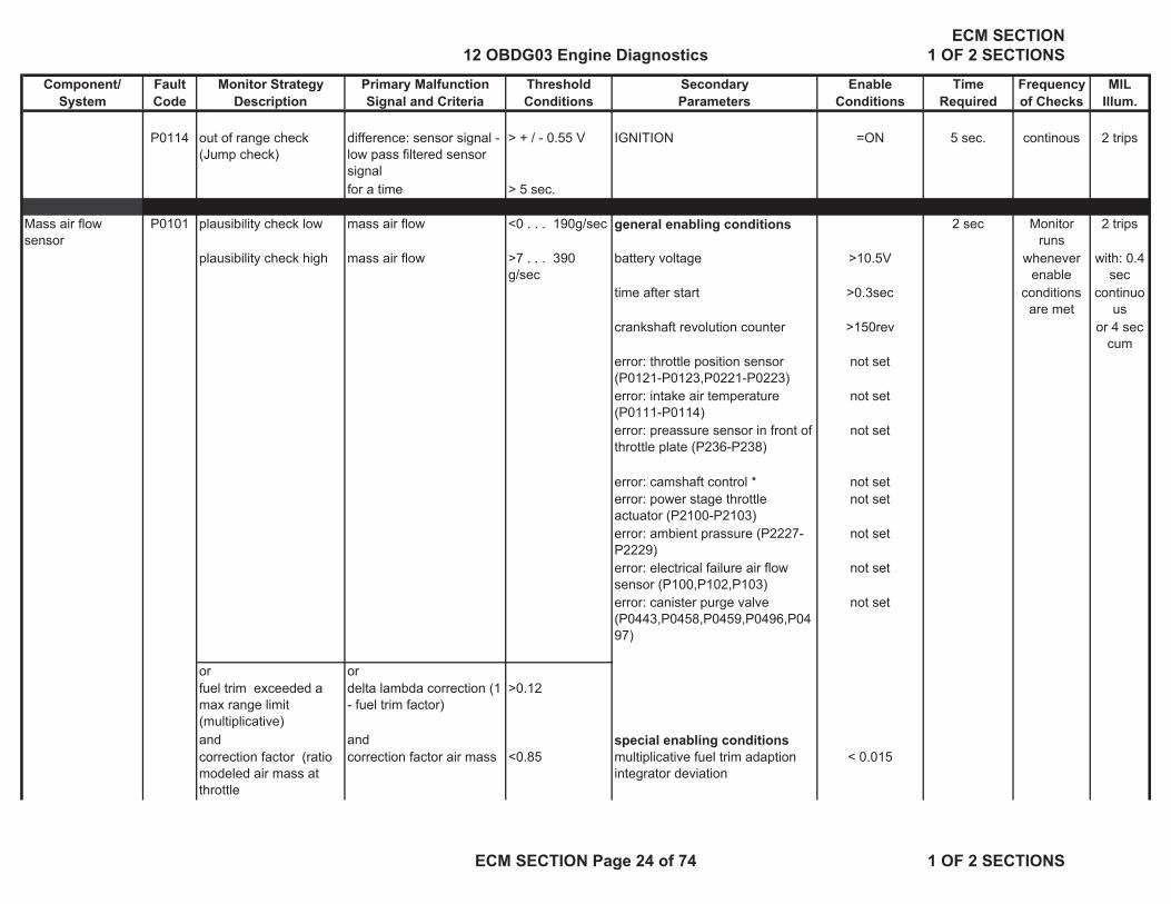
P0114 out of range check (Jump check)
difference: sensor signal - low pass filtered sensor signal
> + / - 0.55 V IGNITION =ON 5 sec. continous 2 trips
for a time > 5 sec.
Mass air flow sensor
P0101 plausibility check low mass air flow <0 . . . 190g/sec general enabling conditions 2 sec Monitor runs
2 trips
plausibility check high mass air flow >7 . . . 390 g/sec
battery voltage >10.5V whenever enable
with: 0.4 sec
time after start >0.3sec conditions are met
continuous
crankshaft revolution counter >150rev or 4 sec cum
error: throttle position sensor (P0121-P0123,P0221-P0223)
not set
error: intake air temperature (P0111-P0114)
not set
error: preassure sensor in front of throttle plate (P236-P238)
not set
error: camshaft control * not seterror: power stage throttle actuator (P2100-P2103)
not set
error: ambient prassure (P2227-P2229)
not set
error: electrical failure air flow sensor (P100,P102,P103)
not set
error: canister purge valve (P0443,P0458,P0459,P0496,P0497)
not set
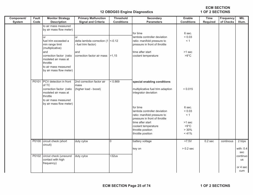
or orfuel trim exceeded a max range limit (multiplicative)
delta lambda correction (1 - fuel trim factor)
>0.12
and and special enabling conditionscorrection factor (ratio modeled air mass at throttle
correction factor air mass <0.85 multiplicative fuel trim adaption integrator deviation
< 0.015
12 OBDG03 Engine DiagnosticsECM SECTION
1 OF 2 SECTIONS
ECM SECTION Page 24 of 74 1 OF 2 SECTIONS
Component/ Fault Monitor Strategy Primary Malfunction Threshold Secondary Enable Time Frequency MILSystem Code Description Signal and Criteria Conditions Parameters Conditions Required of Checks Illum.
to air mass measured by air mass flow meter)
for time 6 sec.or or lambda controller deviation < 0.03fuel trim exceeded a min range limit (multiplicative)
delta lambda correction (1 - fuel trim factor)
<-0.12 ratio: manifold pressure to pressure in front of throttle
< 1
and and time after start >1 seccorrection factor (ratio modeled air mass at throttle
correction factor air mass >1,15 coolant temperature >9°C
to air mass measured by air mass flow meter)
P0101 PCV detection in front of TC
2nd correction factor air mass
< 0.869 special enabling conditions
correction factor (ratio modeled air mass at throttle
(higher load - boost) multiplicative fuel trim adaption integrator deviation
< 0.015
to air mass measured by air mass flow meter)
for time 6 sec.lambda controller deviation < 0.03ratio: manifold pressure to pressure in front of throttle
< 1
time after start >1 seccoolant temperature >9°Cthrottle position > 30%throttle position < 41%
P0100 circuit check (short circuit)
duty cylce 0 battery voltage >7.5V 0.2 sec continous 2 trips
key on > 0.2 sec with: 0.4 sec
P0102 circiut check (unsound contact with high frequency)
duty cylce <32us continuous
or 4 sec cum
12 OBDG03 Engine DiagnosticsECM SECTION
1 OF 2 SECTIONS
ECM SECTION Page 25 of 74 1 OF 2 SECTIONS

Component/ Fault Monitor Strategy Primary Malfunction Threshold Secondary Enable Time Frequency MILSystem Code Description Signal and Criteria Conditions Parameters Conditions Required of Checks Illum.
P0103 circiut check (unsound contact with low frequency)
duty cylce >910us
pressure sensor upstream throttle valve
P0238 cirtcuit continuity - high or open
measured sensor voltage > 4.88 V engine speed > 25 rpm 0.5 sec continuous 2 trips
P0237 cirtcuit continuity - low measured sensor voltage < 0.45 V
P0238 range check - high measured pressure > 300 kPa 2 secP0237 range check - low measured pressure < 50 kPa
P0236 rationality high - diefference measured press. (incl. tolerance)
> 0 hPa engine speed < 1120 rpm 6 sec Monitor runs
2 trips
comparsion between measured pressure and
minus
throttle position < 10% whenever enable
measured ambient pressure
measured ambient pressure (inc. tolerance)
error: ambient pressure sensor (rationality) (P2227-P2229)
not set conditions are met
error: ambient pressure sensor (electrical) (P2228,P2229)
not set
error: pressure sensor upstream throttle plate (electrical) (P0237,P0238)
not set
error: throttle position sensor (P0121-P0123,P0221-P0223)
not set
rationality low - diefference measured
press. (incl. tolerance)< 0hPa
comparsion between measured pressure and
minusmeasured ambient pressure
measured ambient pressure (inc. tolerance)
12 OBDG03 Engine DiagnosticsECM SECTION
1 OF 2 SECTIONS
ECM SECTION Page 26 of 74 1 OF 2 SECTIONS

Component/ Fault Monitor Strategy Primary Malfunction Threshold Secondary Enable Time Frequency MILSystem Code Description Signal and Criteria Conditions Parameters Conditions Required of Checks Illum.
Boost pressure control
P0299 comparison between difference (positive) between
27kPa boost pressure control active 6 sec continuous 2 trips
desired boost pressure set-point boost pressure
engine speed (NDLDRAPU) > 2120 … 3720 rpm
and and atmospheric pressure > 66 kPa current boost pressure measured boost
pressure error: boost pressure
sensor(P0236/P0237/P0238)not set
error: throttle control unit (P0121-P0123,P0221-P0223,P2100-P2103)
not set
error: air mass flow sensor (P0100-P0103)
not set
difference between desired boost pressure - pressure before throttle
> 0
(ambient pressure minus pressure loss of intake)
(boost pressure too low)
P0234 comparison between difference (negative) between
> 25 kPa error: boost pressure sensor(P0236/P0237/P0238)
not set 1.2 s continuous 2 trips
desired boost pressure set-point boost pressure
to
and and 146.6 kPa current boost pressure measured boost
pressure
ormax check measured boost pressure > 220 …. 256
kPaintake air temperature < +30°C 0,30 s continuous 2 trips
(KLMXDLDR)
(boost pressure too high)
12 OBDG03 Engine DiagnosticsECM SECTION
1 OF 2 SECTIONS
ECM SECTION Page 27 of 74 1 OF 2 SECTIONS
Component/ Fault Monitor Strategy Primary Malfunction Threshold Secondary Enable Time Frequency MILSystem Code Description Signal and Criteria Conditions Parameters Conditions Required of Checks Illum.
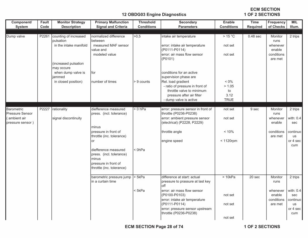
Dump valve P2261 counting of increased pulsation
normalized difference between
>0,5 intake air temperature > 15 °C 0.48 sec Monitor runs
2 trips
in the intake manifold measured MAF sensor value and
error: intake air temperature (P0111-P0114)
not set whenever enable
modeled value error: air mass flow sensor (P0101)
not set conditions are met
(increased pulsation may occure when dump valve is jammed
for conditions for an active supervision phase are
in closed position) number of times > 9 counts Rel. load gradient < 0% - ratio of pressure in front of > 1.05 throttle valve to minimum to
pressure after air filter 3.12 - dump valve is active TRUE
Barometric Pressure Sensor
P2227 rationality diefference measured press. (incl. tolerance)
> 0 hPa error: pressure sensor in front of throttle (P0236-P0238)
not set 9 sec Monitor runs
2 trips
( ambient air pressure sensor )
signal discontinuity
minus
error: ambient pressure sensor (electrical) (P2228, P2229)
not set whenever enable
with: 0.4 sec
pressure in front of throttle (inc. tolerance)
throttle angle < 10% conditions are met
continuous
or engine speed < 1120rpm or 4 sec cum
diefference measured press. (incl. tolerance)
< 0hPa
minuspressure in front of throttle (inc. tolerance)
barometric pressure jump in a curtain time
> 5kPa difference at start: actual pressure to prassure at last key off
> 10kPa 20 sec Monitor runs
2 trips
< 5kPa error: air mass flow sensor (P0100-P0103) not set
whenever enable
with: 0.4 sec
error: intake air temperature (P0111-P0114) not set
conditions are met
continuous
error: pressure sensor upstream throttle (P0236-P0238)
not set
or 4 sec cum
12 OBDG03 Engine DiagnosticsECM SECTION
1 OF 2 SECTIONS
ECM SECTION Page 28 of 74 1 OF 2 SECTIONS

Component/ Fault Monitor Strategy Primary Malfunction Threshold Secondary Enable Time Frequency MILSystem Code Description Signal and Criteria Conditions Parameters Conditions Required of Checks Illum.
error: throttle position sensor (P0121-P0123,P0221-P0223) not seterror: ambient pressure sensor (electrical) (P2228, P2229)
not set
P2228 range check low sensor signal <45kPa key on > 0.2 sec 2 sec continous 2 tripssensor voltage < 0.2V 0.5 sec with: 0.4
seccontinuo
usP2229 range check high sensor signal >115kPa key on > 0.2 sec or 4 sec
cumsensor voltage >4,8V
Idle Speed System
(disabled during cold start)
P0506 functional check desired rpm - actual rpm >100rpm coolant temp. >-11.25° C
10 sec Monitor runs
2 trips
and idle speed controler limit reached
intake air temp >-11.25° C
whenever enable
with: 0.4 sec
P0507 desired rpm - actual rpm <-200rpm engine speed at idle conditions are met
continuous
and idle speed controler limit reached
altitude factor ( sea level = 1.0 ) >0.703factor or 4 sec cum
or time after engine start > 4 sec.fuel cut off due to overspeed
>3count cat heating * inactive
during this idle intrusive evap test not activevehicle speed = 0 km/herror: throttle control unit (P0121-P0123,P0221-P0223,P2100-P2103) not seterror: crankshaft sensor (P0335, P0336, P0338) not set
12 OBDG03 Engine DiagnosticsECM SECTION
1 OF 2 SECTIONS
ECM SECTION Page 29 of 74 1 OF 2 SECTIONS

Component/ Fault Monitor Strategy Primary Malfunction Threshold Secondary Enable Time Frequency MILSystem Code Description Signal and Criteria Conditions Parameters Conditions Required of Checks Illum.
Idle Speed System
(enabled during cold start)
P050A functional check desired rpm - actual rpm >100rpm Engine coolant start temp. < 69°C 5 sec Monitor runs
2 trips
during catalyst heating onengine speed at idle whenever
enable with: 0.4
secP050A desired rpm - actual rpm <-200rpm altitude factor ( sea level = 1.0 ) >0.703factor conditions
are metcontinuo
us
during catalyst heating ontime after engine start > 100sec. or 4 sec
cum cat heating active * TRUE intrusive evap test not active
vehicle speed = 0 km/herror: throttle control unit (P0121-P0123,P0221-P0223,P2100-P2103) not seterror: crankshaft sensor (P0335, P0336, P0338) not set
Vehicle speed sensor
P0503 rationality vehicle speed > 170.87mph 0.4 sec continous 2 trips(high range check) for time > 0.2 sec. continuous with: 0.4
secor 4 sec continuo
usP0501 rationality vehicle speed minus =0mph vehicle speed > 6.213 mph cumulative or 4 sec
cum(stuck check) previous vehicle speed vehicle speed < 317.51 mph time >10sec
P0501 CAN wheel speed message check
CAN wheel speed message corrupt
=corrupt
or missing =missing
P0501 plausibility check vehicle speed < 3.107 mph Fuel system status Fuel cut Monitor runs
during fuel cut off engine speed (NDV, NDV0)
3000 - 1400 rpm coolant temperature > 64.5 °C whenever enable
for a time > 4 sec. conditions are met
12 OBDG03 Engine DiagnosticsECM SECTION
1 OF 2 SECTIONS
ECM SECTION Page 30 of 74 1 OF 2 SECTIONS

Component/ Fault Monitor Strategy Primary Malfunction Threshold Secondary Enable Time Frequency MILSystem Code Description Signal and Criteria Conditions Parameters Conditions Required of Checks Illum.
P0501 plausibility check vehicle speed < 2.485 mph coolant temperature > 64.5 °Cengine load > 80.3 % all injectors active > 0,8 msfor a time > 4 sec. engine speed > 3520 rpm
Crankshaft Position Sensor
P0335 circuit continuity no engine signal =0rpm camshaft revolutions detected >12counts approx. 0.01 sec 1 trip
but phase signals available
5 sec continuous with: 0.4 sec
continuous
rationality check reference gap missing >=6gaps engine speed signal detected > 1 rev or 4 sec cum
( sensor signal but no reference )
P0336 rationality check unexpected re-synchronization
>6count
( loss of reference mark )
rationality check intermittent loss of engine speed signal
> 10 count
P0338 rationality check difference in counted teeth between
>8teeth approx. 1 per rev 1 trip
reference gap position events
2 sec continuous 0.4 s cont.or 4 s cum.
Camshaft Position SensorBank 1 Intake P0342 circuit low differenece between 2
workingcycles< 1 teeth engine in synchronized mode TRUE 10 1 per rev 2 trips
depending on engine speed (KLPHNOKA)
> 8 - 72 count revolutions continuous
P0343 circuit continuity or high differenece between 2 workingcycles
> 1 teeth
depending on engine speed (KLPHNOKA)
> 8 - 72 count
P0341 plausibility check differenece between 2 workingcycles
> 1 or < 1 teeth
depending on engine speed (KLPHNOKA)
> 8 - 72 count
12 OBDG03 Engine DiagnosticsECM SECTION
1 OF 2 SECTIONS
ECM SECTION Page 31 of 74 1 OF 2 SECTIONS

Component/ Fault Monitor Strategy Primary Malfunction Threshold Secondary Enable Time Frequency MILSystem Code Description Signal and Criteria Conditions Parameters Conditions Required of Checks Illum.
P0341 signal check no cam position sensor signal
> 6 count
Bank 1 Exhaust P0366 circuit low differenece between 2 workingcycles
< 1 teeth engine in synchronized mode TRUE
depending on engine speed (KLPHNOKA)
> 8 - 72 count
P0367 circuit continuity or high differenece between 2 workingcycles
> 1 teeth
depending on engine speed (KLPHNOKA)
> 8 - 72 count
P0368 plausibility check differenece between 2 workingcycles
> 1 or < 1 teeth
depending on engine speed (KLPHNOKA)
> 8 - 72 count
P0366 signal check no cam position sensor signal
> 6 count
Bank 2 Intake P0346 circuit low differenece between 2 workingcycles
< 1 teeth engine in synchronized mode TRUE
depending on engine speed (KLPHNOKA)
> 8 - 72 count
P0347 circuit continuity or high differenece between 2 workingcycles
< 1 teeth
depending on engine speed (KLPHNOKA)
> 8 - 72 count
P0348 plausibility check differenece between 2 workingcycles
< 1 teeth
depending on engine speed (KLPHNOKA)
> 8 - 72 count
P0346 signal check no cam position sensor signal
> 6 count
Bank 2 Exhaust P0391 plausibility check differenece between 2 workingcycles
< 1 teeth engine in synchronized mode TRUE
depending on engine speed (KLPHNOKA)
> 8 - 72 count
P0392 circuit low differenece between 2 workingcycles
> 1 teeth
depending on engine speed (KLPHNOKA)
> 8 - 72 count
12 OBDG03 Engine DiagnosticsECM SECTION
1 OF 2 SECTIONS
ECM SECTION Page 32 of 74 1 OF 2 SECTIONS

Component/ Fault Monitor Strategy Primary Malfunction Threshold Secondary Enable Time Frequency MILSystem Code Description Signal and Criteria Conditions Parameters Conditions Required of Checks Illum.
P0393 circuit continuity or high differenece between 2 workingcycles
> 1 or < 1 teeth
depending on engine speed (KLPHNOKA)
> 8 - 72 count
P0391 signal check no cam position sensor signal
> 6 count
Fuel tank pressure sensor
P0450 rationality - fuel tank pressure difference >= 406.25 Pa
time after canister vent valve open
> 4 sec.4,5 continous 2 trips
sensor signal change within time
within = 1 secvehicle speed <= 62.13 mph
(oscillation check) for integrated time >= 25.5 sec calc. ambient temperature > -7.5 °Ccanister purge flow (closed) <= 0 g/sectime after purge valve closes > 0.2 sec.
P0451 rationality - signal range
checkchange of fuel tank pressure
> 1469 Pa time after engine start> 1 sec.
10 sec.
< -3968 Pa time after canister vent valve open
> 4 sec.
vehicle speed > 6.25 mphfor time >= 30 sec.and integrated purge mass flow >= 0.3 g
calculated ambient air temperature
> -7.5 °C
ambient pressure > 68000 Pafuel level < 76 lfuel level > 11 l
ORrationality - drift check difference between fuel
tank pressure> +/- 688 Pa time after engine start > 5 sec.
7 sec.and fuel tank pressure at engine start
Vent solenoid valve open TRUE
Caniter purge flow (closed) <= 0 g/secambient pressure > 68000 Pafuel level < 76 lfuel level > 11 lVehicle speed > 6.25 mphfor time >= 30 sec.and integrated purge mass flow >= 0.3 g
Vehicle speed <= 62.13 mph
12 OBDG03 Engine DiagnosticsECM SECTION
1 OF 2 SECTIONS
ECM SECTION Page 33 of 74 1 OF 2 SECTIONS
Component/ Fault Monitor Strategy Primary Malfunction Threshold Secondary Enable Time Frequency MILSystem Code Description Signal and Criteria Conditions Parameters Conditions Required of Checks Illum.
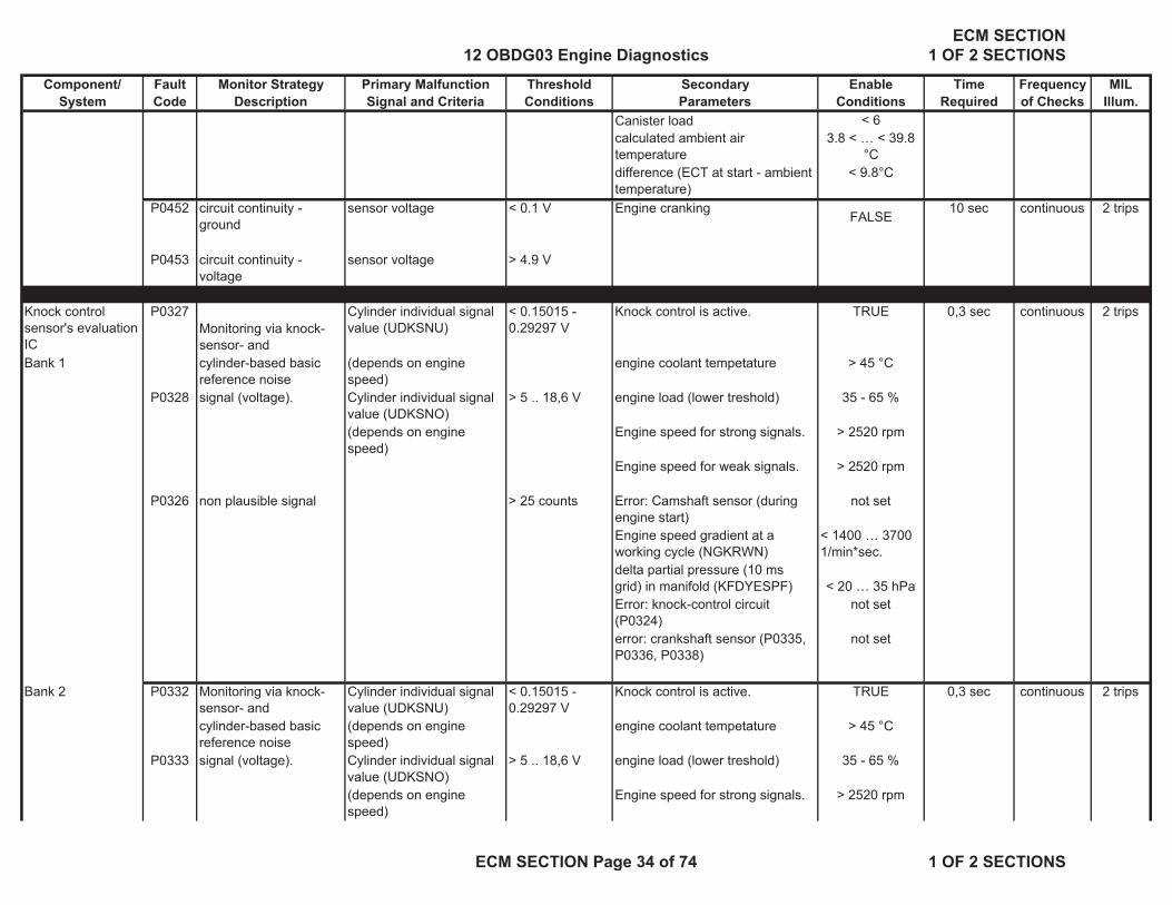
Canister load < 6calculated ambient air temperature
3.8 < … < 39.8 °C
difference (ECT at start - ambient temperature)
< 9.8°C
P0452 circuit continuity - ground
sensor voltage < 0.1 V Engine crankingFALSE
10 sec continuous 2 trips
P0453 circuit continuity - voltage
sensor voltage > 4.9 V
Knock control sensor's evaluation IC
P0327Monitoring via knock-sensor- and
Cylinder individual signal value (UDKSNU)
< 0.15015 - 0.29297 V
Knock control is active. TRUE 0,3 sec continuous 2 trips
Bank 1 cylinder-based basic reference noise
(depends on engine speed)
engine coolant tempetature > 45 °C
P0328 signal (voltage). Cylinder individual signal value (UDKSNO)
> 5 .. 18,6 V engine load (lower treshold) 35 - 65 %
(depends on engine speed)
Engine speed for strong signals. > 2520 rpm
Engine speed for weak signals. > 2520 rpm
P0326 non plausible signal > 25 counts Error: Camshaft sensor (during engine start)
not set
Engine speed gradient at a working cycle (NGKRWN)
< 1400 … 3700 1/min*sec.
delta partial pressure (10 ms grid) in manifold (KFDYESPF) < 20 … 35 hPa
Error: knock-control circuit (P0324)
not set
error: crankshaft sensor (P0335, P0336, P0338)
not set
Bank 2 P0332 Monitoring via knock-sensor- and
Cylinder individual signal value (UDKSNU)
< 0.15015 - 0.29297 V
Knock control is active. TRUE 0,3 sec continuous 2 trips
cylinder-based basic reference noise
(depends on engine speed)
engine coolant tempetature > 45 °C
P0333 signal (voltage). Cylinder individual signal value (UDKSNO)
> 5 .. 18,6 V engine load (lower treshold) 35 - 65 %
(depends on engine speed)
Engine speed for strong signals. > 2520 rpm
12 OBDG03 Engine DiagnosticsECM SECTION
1 OF 2 SECTIONS
ECM SECTION Page 34 of 74 1 OF 2 SECTIONS

Component/ Fault Monitor Strategy Primary Malfunction Threshold Secondary Enable Time Frequency MILSystem Code Description Signal and Criteria Conditions Parameters Conditions Required of Checks Illum.
Engine speed for weak signals. > 2520 rpm
P0331 non plausible signal > 25 counts Error: Camshaft sensor (during engine start)
not set
Engine speed gradient at a working cycle (NGKRWN)
< 1400 … 3700 1/min*sec.
delta partial pressure (10 ms grid) in manifold (KFDYESPF) < 20 … 35 hPa
Error: knock-control circuit (P0324)
not set
error: crankshaft sensor (P0335, P0336, P0338)
not set
Knock control sensor's evaluation IC
P0324 Parity Check number of counts > 5 counts knock control active TRUE 250 working Zero and 2 trips
monitoring of the coefficient RAM of the IC
out of 600 Engine speed gradient at a working cycle (NGKRWN) < 1400 … 3700
1/min*sec.
cylces Test pulse
combustions events delta partial pressure (10 ms grid) in manifold < 20 … 35 hPa
alternate every
error suspicison: knock control test pulse (P0324)
not set 250 working
engine speed > 2000 rpm cycles.
P0324 Response to Zero Pulse
integrator gradient < 200 V/s same as for IC integrator's offset monitoring
monitor IC's integrator gradient
P0324 Response to Test Pulse integrator value of test pulse
< 4.0 Vcoolant temperature > 45 °C
integrator value check Engine speed gradient at a working cycle (NGKRWN)
< 1400 … 3700 1/min*sec.
delta partial pressure (10 ms grid) in manifold (KFDYESPF) < 20 … 35 hPaerror suspicison: knock control zero test (P0324)
not set
12 OBDG03 Engine DiagnosticsECM SECTION
1 OF 2 SECTIONS
ECM SECTION Page 35 of 74 1 OF 2 SECTIONS
Component/ Fault Monitor Strategy Primary Malfunction Threshold Secondary Enable Time Frequency MILSystem Code Description Signal and Criteria Conditions Parameters Conditions Required of Checks Illum.
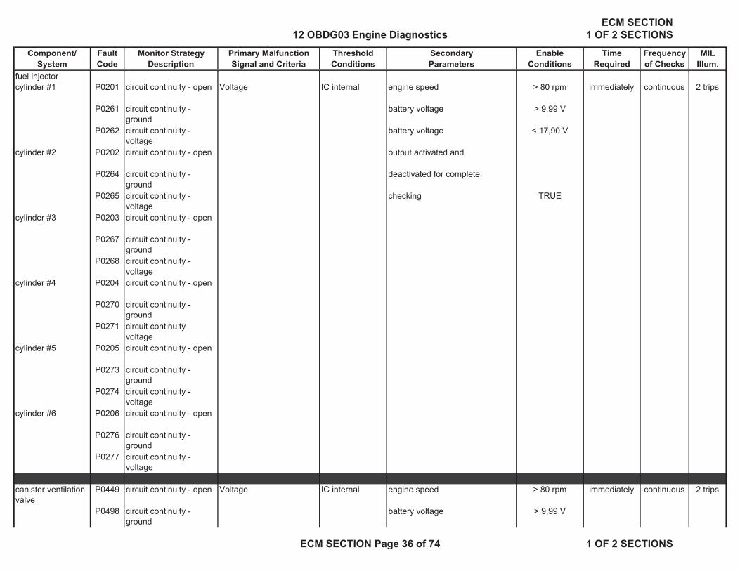
fuel injectorcylinder #1 P0201 circuit continuity - open Voltage IC internal engine speed > 80 rpm immediately continuous 2 trips
P0261 circuit continuity - ground
battery voltage > 9,99 V
P0262 circuit continuity - voltage
battery voltage < 17,90 V
cylinder #2 P0202 circuit continuity - open output activated and
P0264 circuit continuity - ground
deactivated for complete
P0265 circuit continuity - voltage
checking TRUE
cylinder #3 P0203 circuit continuity - open
P0267 circuit continuity - ground
P0268 circuit continuity - voltage
cylinder #4 P0204 circuit continuity - open
P0270 circuit continuity - ground
P0271 circuit continuity - voltage
cylinder #5 P0205 circuit continuity - open
P0273 circuit continuity - ground
P0274 circuit continuity - voltage
cylinder #6 P0206 circuit continuity - open
P0276 circuit continuity - ground
P0277 circuit continuity - voltage
canister ventilation valve
P0449 circuit continuity - open Voltage IC internal engine speed > 80 rpm immediately continuous 2 trips
P0498 circuit continuity - ground
battery voltage > 9,99 V
12 OBDG03 Engine DiagnosticsECM SECTION
1 OF 2 SECTIONS
ECM SECTION Page 36 of 74 1 OF 2 SECTIONS

Component/ Fault Monitor Strategy Primary Malfunction Threshold Secondary Enable Time Frequency MILSystem Code Description Signal and Criteria Conditions Parameters Conditions Required of Checks Illum.
P0499 circuit continuity - voltage
battery voltage < 17,90 V
output activated and deactivated for complete checking TRUE
canister purge valve
P0443 circuit continuity - open Voltage IC internal engine speed > 80 rpm immediately continuous 2 trips
P0458 circuit continuity - ground
battery voltage > 9,99 V
P0459 circuit continuity - voltage
battery voltage < 17,90 V
output activated and deactivated for complete checking TRUE
upstream oxygen sensor heater
Bank #1 P0030 circuit continuity - open Voltage IC internal engine speed > 80 rpm immediately continuous 2 trips
P0031 circuit continuity - ground
battery voltage > 9,99 V
P0032 circuit continuity - voltage
battery voltage < 17,90 V
output activated and deactivated for complete checking TRUE
downstream oxygen sensor heater
Bank #1 P0036 circuit continuity - open Voltage IC internal engine speed > 80 rpm immediately continuous 2 trips
P0037 circuit continuity - ground
battery voltage > 9,99 V
P0038 circuit continuity - voltage
battery voltage < 17,90 V
output activated and deactivated for complete checking TRUE
12 OBDG03 Engine DiagnosticsECM SECTION
1 OF 2 SECTIONS
ECM SECTION Page 37 of 74 1 OF 2 SECTIONS

Component/ Fault Monitor Strategy Primary Malfunction Threshold Secondary Enable Time Frequency MILSystem Code Description Signal and Criteria Conditions Parameters Conditions Required of Checks Illum.
secondary air pump
P2444 circuit continuity - open Voltage IC internal engine speed > 80 rpm immediately continuous 2 trips
P2445 circuit continuity - ground
battery voltage > 9,99 V
P0418 circuit continuity - voltage
battery voltage < 17,90 V
output activated and deactivated for complete checking TRUE
intake camshaft control
Intake Bank #1 P0010 circuit continuity - open Voltage IC internal engine speed > 80 rpm immediately continuous 2 trips
P2088 circuit continuity - ground
battery voltage > 9,99 V with: 0.4 sec
P2089 circuit continuity - voltage
battery voltage < 17,99 V continuous
Intake Bank #2 P0020 circuit continuity - open output activated and or 4 sec cum
P2092 circuit continuity - ground
deactivated for complete
P2093 circuit continuity - voltage
checking TRUE
exhaust camshaft control
P0013 circuit continuity - open
Exhaust Bank #1 P2090 circuit continuity - ground
P2091 circuit continuity - voltage
Exhaust Bank #2 P0023 circuit continuity - open
P2094 circuit continuity - ground
P2095 circuit continuity - voltage
Dump valve turbo P0033 circuit continuity - open Voltage IC internal engine speed > 80 rpm immediately continuous 2 trips
P0034 circuit continuity - ground
battery voltage > 9,99 V
12 OBDG03 Engine DiagnosticsECM SECTION
1 OF 2 SECTIONS
ECM SECTION Page 38 of 74 1 OF 2 SECTIONS

Component/ Fault Monitor Strategy Primary Malfunction Threshold Secondary Enable Time Frequency MILSystem Code Description Signal and Criteria Conditions Parameters Conditions Required of Checks Illum.
P0035 circuit continuity - voltage
battery voltage < 17,90 V
output activated and deactivated for complete checking TRUE
Boost control valve P0244 circuit continuity - open Voltage IC internal engine speed > 80 rpm immediately continuous 2 trips
P0245 circuit continuity - ground
battery voltage > 9,99 V
P0246 circuit continuity - voltage
battery voltage < 17,90 V
output activated and deactivated for complete checking TRUE
Ignition Coilcircuit continuityCylinder #1 P0351 circuit continuity - open
or signal not plausibleVoltage > during
>2 sec engine speed > 400rpm approx. engine 2 trips
or minimum two fault counters
engine speed <5000rpm 1 sec cycle with: 0.4 sec
P2300 circuit continuity - ground Voltage > during
>2 sec battery voltage >10V frequency continuous
P2301 circuit continuity - voltage Voltage > during
>2 sec battery voltage <18V or 4 sec cum
Cylinder #2 P0352 circuit continuity - open or signal not plausible
Voltage > during
>2 sec continuous
or minimum two fault counters
P2303 circuit continuity - ground Voltage > during
>2 sec
P2304 circuit continuity - voltage Voltage > during
>2 sec
Cylinder #3 P0353 circuit continuity - openVoltage > during
>2 sec
or minimum two fault counters
P2306 circuit continuity - ground Voltage > during
>2 sec
12 OBDG03 Engine DiagnosticsECM SECTION
1 OF 2 SECTIONS
ECM SECTION Page 39 of 74 1 OF 2 SECTIONS

Component/ Fault Monitor Strategy Primary Malfunction Threshold Secondary Enable Time Frequency MILSystem Code Description Signal and Criteria Conditions Parameters Conditions Required of Checks Illum.
P2307 circuit continuity - voltage Voltage > during
>2 sec
Cylinder #4 P0354 circuit continuity - openVoltage > during
>2 sec
or minimum two fault counters
P2309 circuit continuity - ground Voltage > during
>2 sec
P2310 circuit continuity - voltage Voltage > during
>2 sec
Cylinder #5 P0355 circuit continuity - openVoltage > during
>2 sec
or minimum two fault counters
P2312 circuit continuity - ground Voltage > during
>2 sec
P2313 circuit continuity - voltage Voltage > during
>2 sec
Cylinder #6 P0356 circuit continuity - openVoltage > during
>2 sec
or minimum two fault counters
P2315 circuit continuity - ground Voltage > during
>2 sec
P2316 circuit continuity - voltage Voltage > during
>2 sec
cold start ignition timing performance
P050B ignition timing efficiency to small during idle
averaged differnce between current ignition efficiency
> 25% condition idle TRUE 10 sec Monitor runs
2 trips
(during catalyst heating)
and desired ignition efficiency
desired ignition efficiency < 88% cumulative whenever enable
cat heating * active conditions are met
time delay for activation 3 secaltitude factor ( sea level = 1.0 ) >0.703factor
engine speed deviaton < 80rpmengine load dynamic < 5%vehicle speed = 0engine load < 90%fuel system status no fuel cut
12 OBDG03 Engine DiagnosticsECM SECTION
1 OF 2 SECTIONS
ECM SECTION Page 40 of 74 1 OF 2 SECTIONS

Component/ Fault Monitor Strategy Primary Malfunction Threshold Secondary Enable Time Frequency MILSystem Code Description Signal and Criteria Conditions Parameters Conditions Required of Checks Illum.
ignition timing efficiency to small during part load
averaged differnce between current ignition efficiency
> 25% condition idle FALSE
and desired ignition efficiency
desired ignition efficiency < 97%
cat heating * activetime delay for activation 3 secaltitude factor ( sea level = 1.0 ) >0.703factor
engine speed deviaton < 80rpmengine load dynamic < 5%vehicle speed > 1,3 mphfuel system status no fuel cut
Electronic Throttle Control
P0638 motor control range check
| powerstage duty cycle | >80% battery voltage > 8V 0.6 sec 0.01 sec immediate
short term for a time >0.6 sec. (recoverable) continuous
5.0 sec(latched)
P0638 motor control range check
( absolute value ) >80% engine speed > 400 rpm
long term for a time > 5 sec. coolant temperature > 5.3 °Cintake air temperature > 5.3 °C
Electronic Throttle Control
P1551 limp-home throttle position
throttle position < 11.3909% vehicle speed <=0mph 5 sec 0.01 sec immediate
out of range OR engine speed < 250rpm at key onthrottle position > 38.7808% engine coolant temperature >= 5.3° C
engine coolant temperature <=84.75° Cintake air temperature >= 5.3° Cintake air temperature <=60° Cbattery voltage > 8Vaccelerator pedal position <14.9%
Electronic Throttle Control
12 OBDG03 Engine DiagnosticsECM SECTION
1 OF 2 SECTIONS
ECM SECTION Page 41 of 74 1 OF 2 SECTIONS

Component/ Fault Monitor Strategy Primary Malfunction Threshold Secondary Enable Time Frequency MILSystem Code Description Signal and Criteria Conditions Parameters Conditions Required of Checks Illum.
P2100 powerstage SPI bus or signal error
output circuits not deactivated
=deactivationfault
- --- 0.1 sec 0.01 sec immediate
P2103 powerstage short circuit as commanded at key on
P2102 powerstage overheating or overcurrent
P2101 powerstage open load
P2101 difference between set and
difference between set and
>4 . . . 50% (DWDKSBAMX)
electronic throttle adaptation not active 0.5 sec 0.01 sec
actual position of throttle blade
actual position of throttle blade
dep. on rate of change
battery voltage > 8V continuous
for a time > 0.5 sec.
Electronic Throttle Control
P2119 functionality of return spring
throttle blade return response
>0.56sec vehicle speed <=0mph 0.56 sec 0.01 sec immediate
engine speed < 250rpm at key onengine coolant temperature >= 5.3° C onceengine coolant temperature <=84.75° C perintake air temperature >= 5.3° C ignitionintake air temperature <=60° C onbattery voltage > 8Vaccelerator pedal position <14.9%
Electronic Throttle Control
P2176 throttle exchange detection
range check poti1 value at lower stop
vehicle speed <=0mph 1 sec 0.01 sec immediate
learn fail throttle potentiometer 1 voltage
< 4.102 V engine speed <40rpm at key on
or or engine coolant temperature >=5.3° C onceP2176 minimum throttle
positionthrottle potentiometer 1 voltage
> 4.5642 V engine coolant temperature <=100° C per
out of range intake air temperature >=5.3° C ignitionor range check poti2 value
at lower stopintake air temperature <=143.3° C on
P2176 initial throttle learn failed
throttle potentiometer 2 voltage
< 0.3369 V battery voltage >9.99V
or or accelerator pedal position <14.9%P2176 learning prohibited due
tothrottle potentiometer 2 voltage
>1.0 V
12 OBDG03 Engine DiagnosticsECM SECTION
1 OF 2 SECTIONS
ECM SECTION Page 42 of 74 1 OF 2 SECTIONS

Component/ Fault Monitor Strategy Primary Malfunction Threshold Secondary Enable Time Frequency MILSystem Code Description Signal and Criteria Conditions Parameters Conditions Required of Checks Illum.
secondary parameters not met
Throttle PositionSensor 1 (primary) P0121 plausibility to model sensor difference >9% engine speed > 480 rpm
0.4 sec.continuous 1 trip
for a time > 0.28 sec. accelerator pedal (WOT) < 48 … 100% continuous with: 0.4 sec
vehicle speed <=0mph continuous
engine coolant temperature >= 5.3° C or 4 sec cum
battery voltage >8Vintake air temperature >=5.3° C
P0122 range check poti voltage
sensor circuit low voltage <0.176V vehicle speed <=0mph
for a time > 0.14 sec engine speed < 250rpmP0123 range check poti
voltagesensor circuit high voltage >4.629V engine coolant temperature >=5.3° C
for a time > 0.14 sec intake air temperature >= 5.3° Cbattery voltage >8V
Sensor 2 (redundant)
P0221 plausibility to model sensor difference >9% engine speed > 480 rpm0.4 sec.
continuous 1 trip
for a time > 0.28 sec. accelerator pedal (WOT) < 48 … 100% continuous with: 0.4 sec
vehicle speed <=0mph continuous
engine coolant temperature >= 5.3° C or 4 sec cum
battery voltage >8Vintake air temperature >=5.3° C
P0222 range check poti voltage
sensor circuit low voltage <0.156V vehicle speed <=0mph
for a time > 0.14 sec engine speed < 250rpmP0223 range check poti
voltagesensor circuit high voltage >4.883V engine coolant temperature >=5.3° C
for a time > 0.14 sec intake air temperature >= 5.3° Cbattery voltage >8V
12 OBDG03 Engine DiagnosticsECM SECTION
1 OF 2 SECTIONS
ECM SECTION Page 43 of 74 1 OF 2 SECTIONS

Component/ Fault Monitor Strategy Primary Malfunction Threshold Secondary Enable Time Frequency MILSystem Code Description Signal and Criteria Conditions Parameters Conditions Required of Checks Illum.
Function Monitoring of Microcontroller
P0606 torque comparison irreversible error of torque comparison
TRUE engine speed >1200rpm 5sec continuous immediate
(PCM level 2 command check)
(current and maximum allowed engine
torque out of range)engine speed comparison
irreversible error of engine speed comparison TRUE engine speed >1200rpm(calculated and measured engine speed
out of range)accelerator pedal signal comparison
irreversible error of accelerator pedal signal comparison TRUE engine speed >1200rpm(synchronism between the two pedal sensors out of range)
monitoring of AD converter queue
irreversible error of AD-converter queue monitoring TRUE engine speed >1200rpm(queue not running)
check of AD-converter signal
irreversible error of AD-converter signal check TRUE engine speed >1200rpm(converted low voltage test impuls out of range)
check of ignition timing irreversible error of comparison of ignition timing value TRUE engine speed >1200rpm(comparison of ignition timing value with its one's complement is wrong)
verification of engine load value
irreversible error of engine load value verification TRUE engine speed >1200rpm(engine load value and verification
12 OBDG03 Engine DiagnosticsECM SECTION
1 OF 2 SECTIONS
ECM SECTION Page 44 of 74 1 OF 2 SECTIONS

Component/ Fault Monitor Strategy Primary Malfunction Threshold Secondary Enable Time Frequency MILSystem Code Description Signal and Criteria Conditions Parameters Conditions Required of Checks Illum.
value are not identical)monitoring of injected fuel mass
irreversible error of fuel mass
TRUE engine speed >1200rpm
(calculated and measured requested fuel mass
out of range)monitoring of mixture correction factor
irreversible error of mixture correction factor
TRUE engine speed >1200rpm
(adapted fuel mixture is out of range)
monitoring of desired air/fuel ratio
irreversible error of air/fuel ratio
TRUE engine speed >1200rpm
(desired air/fuel ration is out of range)
P2105 function controller response check
monitoring module has detected a fault of function controller TRUE engine speed >1200rpm
watchdog output signal check
WDA signal activated TRUE
overvoltage detection internal supply voltage exceeded
TRUE
ECM MonitoringP0605 rationality check - wrong ROM checksum 5-times PCM after-run time of the last TRUE 30 sec at key off immediat
everification of ROM checksum
TRUE driving cycle completly once per
finished tripP0605 rationality check - wrong cyclic ROM
checksum ofTRUE 5 sec 0.04 sec immediat
everification of ROM checksum
critical regions partialchecksum on critcal variables
continous
P0604 writeability check of RAM
RAM read and write test failed
TRUE PCM after-run time of the last TRUE 30 sec at key off immediate
driving cycle completly once perfinished trip
P0604 writeability check of RAM
cyclic RAM read and write test of
1 sec 0.04 sec immediate
critical regions failedTRUE power down calculation in the last
driving cycleTRUE continous
12 OBDG03 Engine DiagnosticsECM SECTION
1 OF 2 SECTIONS
ECM SECTION Page 45 of 74 1 OF 2 SECTIONS

Component/ Fault Monitor Strategy Primary Malfunction Threshold Secondary Enable Time Frequency MILSystem Code Description Signal and Criteria Conditions Parameters Conditions Required of Checks Illum.
completly finishedP0603 rationality check - shut down of power
stages not possible 0.05 sec at key on immediat
eprogramming incomplete
service ECU bits once per
TRUE tripP0603 writeability check of
Time ProcessingTPU parameter RAM read and write
TRUE 0.05 sec at key on immediate
Unit (TPU) parameter RAM test failed
once per
tripP0603 rationality check - wrong TPU code RAM
checksumTRUE 0.3 sec 0.1 sec immediat
everification of Time Processing
continous
Unit (TPU) code RAM checksum
P0603 rationality check - difference between Time Processing Unit
0.3 sec 0.1 sec immediate
time difference check time and PCM time > 0.001 sec continous
Accelerator pedal P 2123 range check high accelerator position sensor voltage 1
> 4.824 V battery voltage is sufficient for 5V accelerator sensor supply > 8V
0,4s continuous immediate
position sensor for a time> 0.2 sec.
with: 0.4 sec
P 2122 range check low accelerator sensor voltage 1
< 0.742 V condition upper limit voilated (see max fault path of FP2P) (P2128)
FALSE
continuous
and condition upper limit voilated (see max fault path of FP1P) (P2123)
FALSE or 4 sec cum
accelerator sensor voltage 2
< 0.625 V battery voltage is sufficient for 5V accelerator sensor supply > 8V
for a time > 0.2 sec.error reaction accelerator-travel sensor limphome (P2127,P2128) FALSE
primary conditions for absolute difference check (P2138)
TRUE
oraccelerator sensor voltage 1
< 0.742 V error reaction accelerator-travel sensor limphome
FALSE
12 OBDG03 Engine DiagnosticsECM SECTION
1 OF 2 SECTIONS
ECM SECTION Page 46 of 74 1 OF 2 SECTIONS

Component/ Fault Monitor Strategy Primary Malfunction Threshold Secondary Enable Time Frequency MILSystem Code Description Signal and Criteria Conditions Parameters Conditions Required of Checks Illum.
for time > 0.2 sec synchronization between voltages 1 and 2 violated
(see values of absolute difference in accelerator sensor
voltages depending on ranges in FP1FP1P absolute difference check below
TRUE
high contact resistance at accelerator voltage 1
FALSE
P 2138 absolute difference check
absolute difference between both
condition lower limit voilated (see min fault path of FP1P) (P2122)
FALSE
fault time accelerator sensor voltages in the range
condition lower limit voilated (see min fault path of FP2P) (P2127) FALSE
from 1.191 V to 1.25 V > 0.254 V error reaction accelerator-travel sensor limphome (P2127,P2128) FALSE
or battery voltage is sufficient for 5V accelerator sensor supply > 8V
absolute difference between both
condition upper limit voilated (see max fault path of FP2P) (P2128)
FALSE
accelerator sensor voltages in the range
condition upper limit voilated (see max fault path of FP1P) (P2123)
FALSE
from 1.25 V to 2.637 V > 0.313 V or absolute difference between both
accelerator sensor voltages in the range
above 2.637 V > 1.699 V and fullfilled for the time > 0.24 sec
P 2128 range check high accelerator sensor
voltage> 4.824 V battery voltage is sufficient for 5V
accelerator sensor supply > 8V
fault time for a time > 0.2 sec.
12 OBDG03 Engine DiagnosticsECM SECTION
1 OF 2 SECTIONS
ECM SECTION Page 47 of 74 1 OF 2 SECTIONS

Component/ Fault Monitor Strategy Primary Malfunction Threshold Secondary Enable Time Frequency MILSystem Code Description Signal and Criteria Conditions Parameters Conditions Required of Checks Illum.
P 2127 range check low accelerator sensor voltage 1
< 0.742 V condition upper limit voilated (see max fault path of FP2P) (P2122)
FALSEand condition upper limit voilated (see
max fault path of FP1P) (P2127)FALSE
accelerator sensor voltage 2
< 0.625 V battery voltage is sufficient for 5V accelerator sensor supply > 8V
for time > 0.2 sec.error reaction accelerator-travel sensor limphome (P2127,P2128) FALSE
primary conditions for absolute difference check (P2138)
TRUE
oraccelerator sensor voltage 2
< 0.625 Verror reaction accelerator-travel sensor limphome (P2127,P2128)
FALSE
for time> 0.2 sec
synchronization between voltages 1 and 2 violated
(see values of absolute difference in accelerator sensor
voltages depending on ranges in FP1FP2P absolute difference check below)
TRUE
high contact resistance at accelerator voltage 1 (P2128)
FALSE
Transmission Control Module
P0700 OBD emission fault signal input =TCM MILFAULT
- --- 0.01 sec 0.01 sec immediate
MIL Illumination requested
detected by the TCM continuous
(Specific TCM DTC shown in freeze frame)
12 OBDG03 Engine DiagnosticsECM SECTION
1 OF 2 SECTIONS
ECM SECTION Page 48 of 74 1 OF 2 SECTIONS

Component/ Fault Monitor Strategy Primary Malfunction Threshold Secondary Enable Time Frequency MILSystem Code Description Signal and Criteria Conditions Parameters Conditions Required of Checks Illum.
demand controlled fuel supply
P069E OBD emission fault signal input =FSCM MILFAULT
- --- 0.01 sec 0.01 sec immediate
(FSCM) detected by the FSCMMIL Illumination requested
OBD ISO-15765 Communication Bus
U0101 Communication with TCM
TCM Message Timeout =message Automatic Transmission equipped 5 sec 0.01 sec immediate
U0402 or Invalid Message Content
=missing, CAN Bus initialized continuous
delayed, consisting of: and readyor ignition on for >3secinvalid battery voltage >10Vcontent battery voltage <18V
normal bus communication runningU0073 ISO-15765 Bus Error Invalid Message Received =invalid CAN Bus initialized 0.5 sec 0.01 sec immediat
eor Dual Port Ram Hardware Error;
=error consisting of: and ready 0.01 sec continuous
or No Communication / Bus Off
=bus off ignition on for >3sec 0.03
battery voltage >10Vbattery voltage <18Vnormal bus communication running--
U0109 Communication with FSCM
FSCM Message Timeout =message FSCM equipped-- 2 sec 0.01 sec immediate
or Invalid Message Content
=missing, CAN Bus initialized-- continuous
delayed, consisting of: and readyor ignition on for >3secinvalid battery voltage >10Vcontent battery voltage <18V
normal bus communication running
Diagnosis Tuning Recognition
P160D Engine performance identification
internal performance comparison
+/- 2 kW engine speed TRUE 5 sec. 1 sec. immediate
external performance comparison (CAN)
+/- 2 kW continuous
12 OBDG03 Engine DiagnosticsECM SECTION
1 OF 2 SECTIONS
ECM SECTION Page 49 of 74 1 OF 2 SECTIONS

Component/ Fault Monitor Strategy Primary Malfunction Threshold Secondary Enable Time Frequency MILSystem Code Description Signal and Criteria Conditions Parameters Conditions Required of Checks Illum.
Diagnosis of ECU programming:
P160E ECU RAM check Diagnosis programming of Engine System
IC internal ignition on TRUE 2 sec. 1 sec. immediate
RPO Regular Production Option Identifier
continuous
Diagnosis of ECU programming:
P0602 ECU RAM check Codeword: calibration for service ECM
>0 4 sec. continuous
"Service ECU"Diagnosis of ECU programming:
P0610 ECU RAM check variant code not programmed
IC internal 2 sec.
"Variantcode"Diagnosis of ECU programming: "VIN"
P0630 ECU RAM check vehicle identification number not programmed
IC internal 2 sec.
Fuel level sensor P0463 fuel level sensor short circuit to battery voltage
sensor voltage > 4.75 V general enabling conditions 2 sec. continuous 2 trips
battery voltage >10V with: 0.4 sec
battery voltage <18V continuous
P0462 fuel level sensor short circiut to ground
sensor voltage < 0.25 V 2 sec. or 4 sec cum
for a time
P0461 fuel level sensor stuck fuel level stays in a band of
2 lspecial enabeling conditions 279.6 miles
for a distance of Error: fuel level sensor (P0461-P0463)
not set
Error: secondary fuel level sensor (P2066-P2068)
not set
error: vehicle speed sensor (P0501-P0503)
not set
engine speed > 80 rpm
12 OBDG03 Engine DiagnosticsECM SECTION
1 OF 2 SECTIONS
ECM SECTION Page 50 of 74 1 OF 2 SECTIONS
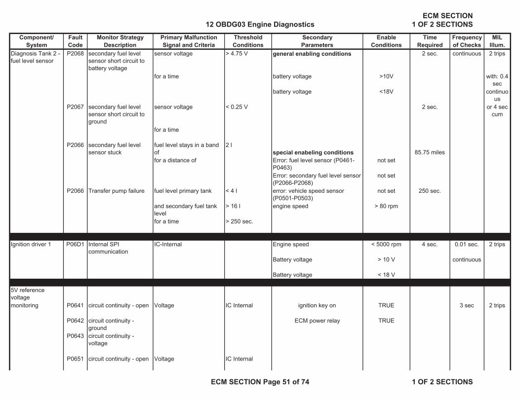
Component/ Fault Monitor Strategy Primary Malfunction Threshold Secondary Enable Time Frequency MILSystem Code Description Signal and Criteria Conditions Parameters Conditions Required of Checks Illum.
Diagnosis Tank 2 - fuel level sensor
P2068 secondary fuel level sensor short circuit to battery voltage
sensor voltage > 4.75 V general enabling conditions 2 sec. continuous 2 trips
for a time battery voltage >10V with: 0.4 sec
battery voltage <18V continuous
P2067 secondary fuel level sensor short circuit to ground
sensor voltage < 0.25 V 2 sec. or 4 sec cum
for a time
P2066 secondary fuel level sensor stuck
fuel level stays in a band of
2 lspecial enabeling conditions 85.75 miles
for a distance of Error: fuel level sensor (P0461-P0463)
not set
Error: secondary fuel level sensor (P2066-P2068)
not set
P2066 Transfer pump failure fuel level primary tank < 4 l error: vehicle speed sensor (P0501-P0503)
not set 250 sec.
and secondary fuel tank level
> 16 l engine speed > 80 rpm
for a time > 250 sec.
Ignition driver 1 P06D1 Internal SPI communication
IC-Internal Engine speed < 5000 rpm 4 sec. 0.01 sec. 2 trips
Battery voltage > 10 V continuous
Battery voltage < 18 V
5V reference voltagemonitoring P0641 circuit continuity - open Voltage IC Internal ignition key on TRUE 3 sec 2 trips
P0642 circuit continuity - ground
ECM power relay TRUE
P0643 circuit continuity - voltage
P0651 circuit continuity - open Voltage IC Internal
12 OBDG03 Engine DiagnosticsECM SECTION
1 OF 2 SECTIONS
ECM SECTION Page 51 of 74 1 OF 2 SECTIONS

Component/ Fault Monitor Strategy Primary Malfunction Threshold Secondary Enable Time Frequency MILSystem Code Description Signal and Criteria Conditions Parameters Conditions Required of Checks Illum.
P0652 circuit continuity - ground
P0653 circuit continuity - voltage
P0697 circuit continuity - open Voltage IC Internal
P0698 circuit continuity - ground
P0699 circuit continuity - voltage
Real time clockEngine off timer Status Check
P2610 engine off timer signal check
engine off timer state >= 3 engine speed > 240 rpm 0.1 sec. 2 trips
real time clock active TRUE(State 3 corresponds to engine off time which does not match the time from the ETC watchdog
time, and a battery disconnection has not been detected)
Real time clock Engine off timer Rationality
P2610 engine off timer incremental
reference clock time delta -
> 6 counts engine speed > 240 rpm 0.1 sec. 2 trips
check check Engine Off Timer delta failure counts >= 3 counts
reference clock time delta -
< 6 counts engine speed > 240 rpm
Engine Off Timer delta failure counts >= 3 counts
or
reference clock and Engine Off Timer (EOT)
> 6 seconds ECM afterrun complete TRUE
required synchronization time >
12 OBDG03 Engine DiagnosticsECM SECTION
1 OF 2 SECTIONS
ECM SECTION Page 52 of 74 1 OF 2 SECTIONS

Component/ Fault Monitor Strategy Primary Malfunction Threshold Secondary Enable Time Frequency MILSystem Code Description Signal and Criteria Conditions Parameters Conditions Required of Checks Illum.
(reference clock is an independently captured time value based on the ECMprocessor clock)
Brake Pedal Position Sensor
P057C Brake Pedal Position Sensor Voltage
< 0.25V none 0.5 sec 2 trips
Circuit Low
Brake Pedal Position Sensor
P057D Brake Pedal Position Sensor Voltage
>4.75V none 0.5 sec 2 trips
Circuit High
end * see glossary of secondary parameter
12 OBDG03 Engine DiagnosticsECM SECTION
1 OF 2 SECTIONS
ECM SECTION Page 53 of 74 1 OF 2 SECTIONS

Engine Support Tables
P0011, P0021, P000A, P000C
KFDWNWDMXE (internal manufacturer cross reference)
P0021, P0024, P000B, P000D KFDWNWDMXA (internal manufacturer cross reference)
Maximum Allowed Deviation - Intake Camshaft Positiondegrees crank Modeled Engine Oil Temperature ( ° C )
Engine Speed (rpm) 800 2000 4000 6000 129.9984375800 6.00 6.00 7.00 9.00 11.001200 6.00 6.00 6.00 6.00 7.001600 6.00 6.00 6.00 6.00 7.002000 6.00 6.00 6.00 6.00 6.002500 6.00 6.00 6.00 6.00 6.004000 6.00 6.00 6.00 6.00 6.00
KFTDDNWNPE (internal manufacturer cross reference)Maximum Allowed Deviation - Intake Camshaft Position
degrees crank Engine Speed (rpm)Modeled Engine Oil Temperature ( ° C ) 800 2000 4000 6000
-30 2.00 2.00 2.00 2.0020 1.60 1.60 1.60 1.6040 1.20 1.20 1.20 1.20110 1.20 1.20 1.20 1.20120 1.20 1.20 1.20 1.20
KFTDDNWNPA (internal manufacturer cross reference)Maximum Allowed Deviation - Intake Camshaft Position
degrees crank Engine Speed (rpm)Modeled Engine Oil Temperature ( ° C ) 800 2000 4000 6000
-30 2.00 2.00 2.00 2.0020 1.60 1.60 1.60 1.6040 1.50 1.50 1.50 1.50110 1.50 1.50 1.50 1.50120 1.50 1.50 1.50 1.50
P0111 KLTFA1ML (internal manufacturer cross reference)Minimum airmass to enable the stuck check monitor
temperature difference engine coolant - ambient temperature (°C) -30 -9.75 0
airmass (kg) 15.019 11.014 4.005
P0128 TWADTHMS (internal manufacturer cross reference)Engine start temperature depend. time for freezing temperature model of thermostat monitoring
-48.00 -40.50 -33.00 -10.50 12.00 27Time (sec) 22.00 18.00 16.00 16.00 16.00 16.00
P0134 (internal manufacturer cross reference)USDB0 Minimum Voltage for evaluation 0.400 VUSREF Maximum Voltage for evaluation cold sensor 0.600 VUSREFHOT Maximum Voltage for evaluation hot sensor 0.550 V
P0130 USMIN Minimum Voltage for evaluation 0.060 VUSREMH Maximum Voltage for evaluation 0.400 VUSREFHKLT Minimum Voltage for evaluation 0.600 VUSMAX Maximum Voltage for evaluation 1.080 V
Engine Coolant Temperature at start (°C)
12 OBDG03 Engine DiagnosticsECM SECTION
1 OF 2 SECTIONS
ECM SECTION Page 54 of 74 1 OF 2 SECTIONS

Engine Support TablesP0133 (internal manufacturer cross reference)
NTPKTU Minimum engine speed 1000.000 rpmNTPKTO Maximum engine speed 3000.000 rpmRLTPVKU Minimum load 18.000 %RLTPVKO Maximim load 79.500 %
P0135 KFRINV (internal manufacturer cross reference)Sensor Element (Ceramic) Impedance, Nominal Value - Secondary O2 Sensor
Ohms Modeled Exhaust Gas Temperature at Secondary O2 Sensor ( ° C )Normalized Heater Power 299.990625 374.990625 449.990625 524.990625 599.990625
0.68 328 256 192 136 1040.78 232 192 144 112 881.00 136 120 104 88 88
FRINV1 (internal manufacturer cross reference)Multiplication Factor for Internal Resistance KFRINH Nominal Value - Secondary O2 Sensor
Modeled Exhaust Gas Temperature at Secondary O2 Sensor ( ° C )269.990625 350.00625 429.9984375 509.990625 590.00625
factor 20.00 10.00 5.00 3.00 3.00
(internal manufacturer cross reference)TADHMNV Minimum modelled exhaust temperature 300 °CTADHMXV Maximum modelled exhaust temperature 550 °C
P0141 KFRINH (internal manufacturer cross reference)Sensor Element (Ceramic) Impedance, Nominal Value - Secondary O2 Sensor
Ohms Modeled Exhaust Gas Temperature at Secondary O2 Sensor ( ° C )Normalized Heater Power 300 375 450 525 600
0.68 560 424 344 272 2080.78 344 288 240 200 1761.0 184 168 152 136 120
FRINH1 (internal manufacturer cross reference)Multiplication Factor for Internal Resistance KFRINH Nominal Value - Secondary O2 Sensor
Modeled Exhaust Gas Temperature at Secondary O2 Sensor ( ° C )270 350 430 510 590
factor 30.00 20.00 10.00 6.00 4.00
(internal manufacturer cross reference)TADHMNH Minimum modelled exhaust temperature 350 °CTADHMXH Maximum modelled exhaust temperature 550 °C
P0234 KLMXDLDR (internal manufacturer cross reference)Error threshold for absolute boost pressure too high
Intake air temperature (°C) -48 -21 6.75 30 61.5 88.5 116.25 143.25pressure threshold (kPa) 2200 2300 2400 2560 2560 2560 2560 2560
P0299 NDLDRAPU (internal manufacturer cross reference)Engine speed threshold to enable diagnosis
ambient pressure (hPa) 600 980engine speed (1/min) 3720 2120
12 OBDG03 Engine DiagnosticsECM SECTION
1 OF 2 SECTIONS
ECM SECTION Page 55 of 74 1 OF 2 SECTIONS

Engine Support TablesP0300, P0301, P0302 MISALUN (internal manufacturer cross reference)P0303, P0304, P0305, Indicated drive torque for enabling the misfire monitorP0306
600.00 1320.00 2400.00 3120.00 3800.00 4720 5520 6120Torque ( % ) 5.47 8.20 9.77 10.94 12.89 16.015625 18.75 20.70313
NGALUN (internal manufacturer cross reference)Engine Speed Gradient for disabling the misfire monitor
600.00 1320.00 2400.00 3120.00 3800.00 4720 5520 6120Engine Speed Gradient ( RPM / s) 12799.99 12799.99 12799.99 12799.99 12799.99 12799.99 12799.99 12799.99
KFKSWFS (internal manufacturer cross reference)Misfire Weighing Factors for Catalyst Protection
Indicated Engine TorqueEngine Speed ( RPM ) 14.84375 30.078125 39.84375 50 60.15625 75
1000 32 32 32 32 37 372000 32 32 37 32 37 593000 32 32 37 37 48 484000 32 37 43 53 69 64
5000.00 32 43 59 75 85 856000.0 32 59 96 107 114 80
AHEKSB1 Summary Counter weighed misfire for Catalyst Gemaging Misfire 3200.00
Misfirerate for Catalyst Protection in % Calculated from KFKSWFS and AHEKSB1: Value=AHEKSB1/KFKSWFS/600*100 (%)Indicated Engine Torque
Engine Speed ( RPM ) 14.84375 30.078125 39.84375 50 60.15625 751000 16.67 16.67 16.67 16.67 14.41 14.412000 16.67 16.67 14.41 16.67 14.41 9.043000 16.67 16.67 14.41 14.41 11.11 11.114000 16.67 14.41 12.40 10.06 7.73 8.33
5000.00 16.67 12.40 9.04 7.11 6.27 6.276000.0 16.67 9.04 5.56 4.98 4.68 6.67
P0326, P0327, P0328, P0331, P0332, P0333 NGKRWN (internal manufacturer cross reference)
RPM dynamic threshold for disabling knock diagnosisRPM 400 800 1200 1600 2000 2400 2800 3200 3600 4000 4400 4800 5200 5600 6000 6400
RPM per second 1400 1550 1700 1950 2200 2450 2650 2800 3000 3100 3250 3400 3500 3600 3700 3700
KFDYESPF (internal manufacturer cross reference)Intake Manifold Pressure delta for disabling knock diagnosis
Intake Manifold Press (kPa)ECT ( ° C ) 400 800 1200 1600 2000 2400 2800 3200 3600 4000 4400 4800 5200 5600 6000 6400
50.25 35 34 24 20 19 19 18 18 18 19 19 19 19 20 21 2169.75 30 28 27 23 21 21 20 20 20 20 20 20 20 19 20 20
90 24 24 25 22 22 22 22 22 22 22 21 21 21 19 20 20120 22 21 21 23 22 24 25 23 24 22 20 20 20 19 20 20
P0327, P0332 UDKSNU (internal manufacturer cross reference)Reference voltage threshold for knock sensor diagnosis - Lower Limit
400 800 1200 1600 2000 2400 2800 3200 3600 4000 4400 4800 5200 5600 6000 6400Peak RMS Voltage ( V ) 0.150 0.150 0.150 0.150 0.150 0.150 0.150 0.293 0.293 0.293 0.293 0.293 0.293 0.293 0.293 0.293
Engine Speed ( RPM )
Engine Speed ( RPM )
Engine Speed (RPM)
Engine Speed ( rpm )
12 OBDG03 Engine DiagnosticsECM SECTION
1 OF 2 SECTIONS
ECM SECTION Page 56 of 74 1 OF 2 SECTIONS

Engine Support TablesP0328, P0333 UDKSNO (internal manufacturer cross reference)
Reference voltage threshold for knock sensor diagnosis - Upper Limit
400 800 1200 1600 2000 2400 2800 3200 3600 4000 4400 4800 5200 5600 6000 6400Peak RMS Voltage ( V ) 5.000 5.000 5.000 5.000 5.000 5.400 6.000 6.600 7.800 9.000 10.350 11.850 13.500 15.300 17.100 18.600
P0341, P0342, P0343 KLPHNOKA (internal manufacturer cross reference)P0346, P0347, P0348 Threshold for number of counts for detection of camshaft position sensor errorP0366, P0367, P0368P0391, P0392, P0393 600.000 1600.000 3200.000 7200.000
Number of Counts 8.000 17.000 34.000 72.000
P0420 RLKTDMN (internal manufacturer cross reference)Engine Load lower limit for enabling catalyst monitor
1000.000 1520.000 2000.000 2520.000 3000.000Engine Load (%) 18.000 18.000 18.000 18.000 18.000
RLKTDMX (internal manufacturer cross reference)Engine Load upper limit for enabling catalyst monitor
1000.000 1520.000 2000.000 2520.000 3000.000Engine Load (%) 80.250 80.250 77.250 72.750 69.750
TVKTDMTPE (internal manufacturer cross reference)Time Delay for enabling catalyst monitor after secondary O2 sensor has reached dewpoint end
0.000 20.250 39.750 60.000Time Delay (sec) 10.000 20.000 30.000 40.000
P0446, P0496, P0497, FSTDMN Minimum Fueltanklevel 11.0P0455 FSTDMX Maximum Fueltanklevel 76.0
TUMTDLU Minimum Ambient Temperature 2.0TUMTDLO Maximum Ambient Temperature 38.0TMSTLDMN Minimum Coolant Temperature at Engine Start 2.0TMSTLDMX Maximum Coolant Temperature at Engine Start 38.0
Engine Coolant Temperature at Start ( ° C )
Engine Speed ( rpm )
Engine Speed (RPM)
Engine Speed (RPM)
Engine Speed (RPM)
12 OBDG03 Engine DiagnosticsECM SECTION
1 OF 2 SECTIONS
ECM SECTION Page 57 of 74 1 OF 2 SECTIONS

Engine Support TablesP0442 KFEONVPT (internal manufacturer cross reference)
Vacuum / Pressure Threshold for Fuel Tank Leak DetectionVacuum / Pressure (hPa)
Fuel Level (%) 0 5.25 9.75 15 20.25 24.75 30 35.25 39.755 1.80 1.91 2.00 2.35 2.70 3.00 3.35 3.70 4.0010 1.74 1.84 1.93 2.27 2.61 2.90 3.24 3.58 3.8720 1.63 1.69 1.80 2.12 2.43 2.70 3.02 3.33 3.6030 1.51 1.55 1.67 1.96 2.25 2.50 2.79 3.08 3.3340 1.40 1.40 1.53 1.80 2.07 2.30 2.57 2.84 3.0750 1.35 1.35 1.40 1.65 1.89 2.10 2.34 2.59 2.8060 1.29 1.30 1.33 1.54 1.75 1.93 2.14 2.35 2.5370 1.25 1.25 1.27 1.44 1.62 1.77 1.94 2.12 2.2780 1.20 1.20 1.20 1.34 1.48 1.60 1.74 1.88 2.00
Tank Capacity 82.5 LitersVacuum / Pressure (Pa) Ambient Temperature (Model) ( ° C )
Fuel Level (%) 0 5.25 9.75 15 20.25 24.75 30 35.25 39.755 180 191 200 235 270 300 335 370 40010 174 184 193 227 261 290 324 358 38720 163 169 180 212 243 270 302 333 36030 151 155 167 196 225 250 279 308 33340 140 140 153 180 207 230 257 284 30750 135 135 140 165 189 210 234 259 28060 129 130 133 154 175 193 214 235 25370 125 125 127 144 162 177 194 212 22780 120 120 120 134 148 160 174 188 200
P0455 KLTLDSFS05 (internal manufacturer cross reference)Vacuum Gradient Threshold for Fuel Tank Leak DetectionFuel Level liters 0 10 20 30 40 50 60 70 75 80hPa / sec 0.150 0.150 0.160 0.170 0.175 0.180 0.185 0.190 0.190 0.190
Tank Capacity 82.5 LitersFuel Level ( % ) 0 12.1 24.2 36.4 48.5 60.6 72.7 84.8 90.9 97.0Pa / sec 15.0 15.0 16.0 17.0 17.5 18.0 18.5 19.0 19.0 19.0
P0451 TUMDSTDMN Minimum Coolant Temperature at Engine Start 3.8 °CTUMDSTDMX Maximum Coolant Temperature at Engine Start 39.8 °C
P0501 (internal manufacturer cross reference)NDV Minimum engine speed for diagnosis 1400 rpmNDV0 Maximum engine speed for diagnosis 3000 rpm
P2101 DWDKSBAMX (internal manufacturer cross reference)Maximum Throttle Angle Deviation per computation cycle
Percent Throttle Opening ( % )0 0.300598145 0.999450684 5.000305176 14.99938965
Percent Throttle Delta ( % ) 4 6 11 20 50
End Cal Tables
Ambient Temperature (Model) ( ° C )
12 OBDG03 Engine DiagnosticsECM SECTION
1 OF 2 SECTIONS
ECM SECTION Page 58 of 74 1 OF 2 SECTIONS

Glossary of Secondary Parameters
Secondary parameters Enable condition Definitiondew point exeeded at primary O2 sensor TRUE time integrated heat quantity is larger than calibrated map values dependent on
engine start temperature (0.46 .. 1262 KJ)exhaust pipe temperature at primary oxygen sensor > 60°C
dew point exeeded at secondary O2 sensor TRUE time integrated heat quantity is larger than calibrated map values dependent on engine start temperature (1.8 … 1400 KJ)exhaust pipe temperature at primary oxygen sensor > 60°C
primary sensor heating active TRUE dew point exeeded at primary O2 sensorengine speed > 680 rpmbattery voltage < 18 Vengine temperature > -9.8 °Cerror: primary oxygen sensor --> not set
secondary air system active intake air temperature > - 11 … < 80 °Cengine coolant temperature > - 11 … < 120 °Cengine speed < 3500 rpmmass airflow < 100 g/sec.battery voltage > 10 … < 18 Vcat heating --> active
cat heating active nmot > 680rpmaltitude < 3000mintake air temp. > -12°Cengine start temperature -10,5°C < … < 69,75°Cdifference of intake air. temp minus engine coolant start temp. <=15°Cerror: air flow meter --> not seterror: intake air temperature sensor -->not seterror: engine temperature sensor --> not seterror: ambient pressure sensor --> not set
error: camshaft control system not set P0011, P0021, P0014, P0024, P000A, P000B, P000C, P000DP0341-P0343, P0366-P0368, P0346-P0348, P0391-P0393
error: evap. canister purge system not set P0449, P0498, P0499, P0443, P0458, P0459, P0442, P0446, P0455, P0496, P0497
error: camshaft control circuit not set P0341-P0346, P0366-P0368, P0346-P0348, P0391-P0393
12 OBDG03 Engine DiagnosticsECM SECTION
1 OF 2 SECTIONS
ECM SECTION Page 59 of 74 1 OF 2 SECTIONS
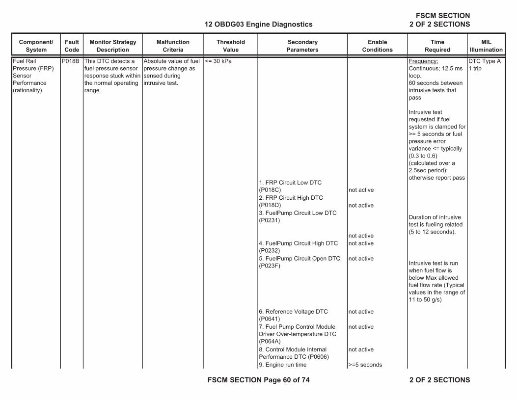
Component/System
FaultCode
Monitor StrategyDescription
MalfunctionCriteria
ThresholdValue
SecondaryParameters
Enable Conditions
TimeRequired
MILIllumination
Fuel Rail Pressure (FRP) Sensor Performance (rationality)
P018B This DTC detects a fuel pressure sensor response stuck within the normal operating range
Absolute value of fuel pressure change as sensed during intrusive test.
<= 30 kPa
1. FRP Circuit Low DTC (P018C) not active
Frequency:Continuous; 12.5 ms loop. 60 seconds between intrusive tests that pass
Intrusive test requested if fuel system is clamped for >= 5 seconds or fuel pressure error variance <= typically (0.3 to 0.6) (calculated over a 2.5sec period); otherwise report pass
DTC Type A1 trip
2. FRP Circuit High DTC (P018D) not active 3. FuelPump Circuit Low DTC (P0231)
not active
Duration of intrusive test is fueling related (5 to 12 seconds).
4. FuelPump Circuit High DTC (P0232)
not active
5. FuelPump Circuit Open DTC (P023F)
not activeIntrusive test is run when fuel flow is below Max allowed fuel flow rate (Typical values in the range of 11 to 50 g/s)
6. Reference Voltage DTC (P0641)
not active
7. Fuel Pump Control Module Driver Over-temperature DTC (P064A)
not active
8. Control Module Internal Performance DTC (P0606)
not active
9. Engine run time >=5 seconds
12 OBDG03 Engine DiagnosticsFSCM SECTION
2 OF 2 SECTIONS
FSCM SECTION Page 60 of 74 2 OF 2 SECTIONS

Component/System
FaultCode
Monitor StrategyDescription
MalfunctionCriteria
ThresholdValue
SecondaryParameters
Enable Conditions
TimeRequired
MILIllumination
10. Emissions fuel level (PPEI $3FB)
not low
11. Fuel pump control enabled 12. Fuel pump control state normal or FRP
Rationality control 13. Engine fuel flow > 0.047 g/s
14. ECM fuel control system failure (PPEI $1ED)
failure has not occurred
Fuel Rail Pressure (FRP) Sensor Circuit Low Voltage
P018C This DTC detects if the fuel pressure sensor circuit is shorted low
FRP sensor voltage < 0.14 V
Ignition Run or Crank
72 failures out of 80 samples
1 sample/12.5 ms
DTC Type A1 trip
Fuel Rail Pressure (FRP) Sensor Circuit High Voltage
P018D This DTC detects if the fuel pressure sensor circuit is shorted high
FRP sensor voltage > 4.86 V
Ignition Run or Crank
72 failures out of 80 samples
1 sample/12.5 ms
DTC Type A1 trip
Fuel Pump Control Circuit Low Voltage
P0231 This DTC detects if the fuel pump control circuit is shorted to low
Fuel Pump Current > 14.48A
Ignition Run or Crank
72 test failures in 80 test samples if Fuel Pump Current <100A
DTC Type A1 trip
OR HS Comm enabledOR 1 sample/12.5 msFuel Pump Control enabledAND Ignition Run/Crank Voltage 9V < voltage < 32V
12 OBDG03 Engine DiagnosticsFSCM SECTION
2 OF 2 SECTIONS
FSCM SECTION Page 61 of 74 2 OF 2 SECTIONS

Component/System
FaultCode
Monitor StrategyDescription
MalfunctionCriteria
ThresholdValue
SecondaryParameters
Enable Conditions
TimeRequired
MILIllumination
Fuel Pump Control Circuit High Voltage
P0232 This DTC detects if the fuel pump control circuit is shorted to high
Voltage measured at fuel pump circuit
> 3.86 V Commanded fuel pump output 0% duty cycle (off) 36 test failures in 40 test samples; 1 sample/12.5ms
DTC Type A1 trip
Fuel pump control enable False Pass/Fail determination made only once per trip
Time that above conditions are met
>=4.0 seconds
Fuel Pump Control Circuit (Open)
P023F This DTC detects if the fuel pump control circuit is open
Fuel Pump Current <=0.5A
Ignition Run or Crank
72 test failures in 80 test samples; 1 sample/12.5ms
DTC Type A1 trip
AND OR Fuel Pump Duty Cycle >20% HS Comm enabled
OR Fuel Pump Control enabledAND Ignition Run/Crank Voltage 9V < voltage < 32V
Fuel System Control Module Enable Control Circuit
P025A This DTC detects if there is a fault in the fuel pump control enable circuit
PPEI (PPEI (Powertrain Platform Electrical Interface) Fuel System Request ($1ED)
Fuel Pump Control Module Enable Control Circuit
Ignition Run or Crank
72 failures out of 80 samples
1 sample/12.5 ms
DTC Type A1 trip
AND PPEI Fuel System Request ($1ED)
valid
Control Module Read Only Memory (ROM)
P0601 This DTC will be stored if any software or calibration check sum is incorrect
Calculated Checksum (CRC16)
stored checksum for any of the parts (boot, software, application calibration, system calibration)
Ignition Run or Crank
1 failure if it occurs during the first ROM test of the ignition cycle, otherwise 5 failures
DTC Type A1 trip
12 OBDG03 Engine DiagnosticsFSCM SECTION
2 OF 2 SECTIONS
FSCM SECTION Page 62 of 74 2 OF 2 SECTIONS

Component/System
FaultCode
Monitor StrategyDescription
MalfunctionCriteria
ThresholdValue
SecondaryParameters
Enable Conditions
TimeRequired
MILIllumination
OR Frequency:Runs continuously in the background
HS Comm enabledOR Fuel Pump Control enabled
Control Module Not Programmed
P0602 Indicates that the FSCM needs to be programmed
This DTC is set via calibration, when
KeMEMD_b_NoStartCal
= TRUE
Ignition Run or Crank
Runs once at power up
DTC Type A1 trip
OR HS Comm enabledOR Fuel Pump Control enabled
Control Module Long Term Memory Reset
P0603 Non-volatile memory checksum error at controller power-up
Checksum at power-up
checksum at power-down
Ignition Run or Crank
1 failure
Frequency:Once at power-up
DTC Type A1 trip
OR HS Comm enabledOR Fuel Pump Control enabled
Control Module Random Access Memory (RAM)
P0604 Indicates that control module is unable to correctly write and read data to and from RAM
Data read Data written
Ignition Run or Crank
1 failure if it occurs during the first RAM test of the ignition cycle, otherwise 5 failures
DTC Type A1 trip
OR Frequency:HS Comm enabled Runs continuously in
the background.OR Fuel Pump Control enabled
12 OBDG03 Engine DiagnosticsFSCM SECTION
2 OF 2 SECTIONS
FSCM SECTION Page 63 of 74 2 OF 2 SECTIONS

Component/System
FaultCode
Monitor StrategyDescription
MalfunctionCriteria
ThresholdValue
SecondaryParameters
Enable Conditions
TimeRequired
MILIllumination
Control Module Internal Performance
1. Main Processor Configuration Register Test
P0606
1. For all I/O configuration register faults:
•Register contents
Incorrect value. Ignition Run or Crank
Tests 1 and 2 1 failureFrequency:Continuously (12.5ms)
DTC Type A1 trip
OR HS Comm enabledOR Fuel Pump Control enabled
2. Processor clock test
2. For Processor Clock Fault: •EE latch flag in EEPROM. OR
0x5A5A
1. For all I/O configuration register faults: •KeMEMD_b_ProcFltCfgRegEnbl
TRUE
Test 33 failures out of 15 samples
1 sample/12.5 ms• RAM latch flag. 0x5A 2. For Processor Clock Fault:
•KeMEMD_b_ProcFltCLKDiagEnbl
TRUE
3. External watchdog test
3. For External Watchdog Fault:• Software control of fuel pump driver
Control Lost
3. For External Watchdog Fault:•KeFRPD_b_FPExtWDogDiagEnbl
TRUE3. For External Watchdog Fault:•Control Module ROM(P0601)
not active3. For External Watchdog Fault:•Control Module RAM(P0604)
not activeControl Module Long Term Memory (EEPROM) Performance
P062F Indicates that the NVM Error flag has not been cleared
Last EEPROM write Did not complete
Ignition Run or Crank
1 test failureOnce on controller power-up
DTC Type A1 trip
OR
This DTC indicates the FSCM has detected an internal processor fault or external watchdog fault (PID 2032 discriminates the source of the fault )
12 OBDG03 Engine DiagnosticsFSCM SECTION
2 OF 2 SECTIONS
FSCM SECTION Page 64 of 74 2 OF 2 SECTIONS
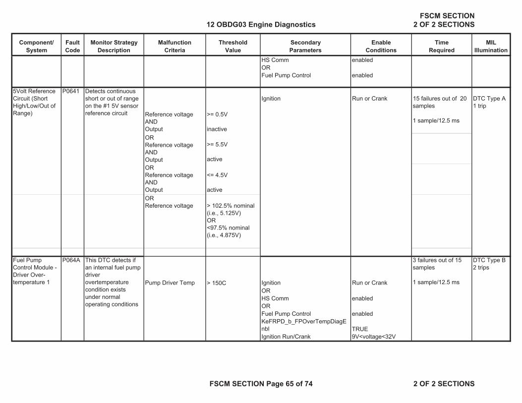
Component/System
FaultCode
Monitor StrategyDescription
MalfunctionCriteria
ThresholdValue
SecondaryParameters
Enable Conditions
TimeRequired
MILIllumination
HS Comm enabledOR Fuel Pump Control enabled
5Volt Reference Circuit (Short High/Low/Out of Range)
P0641 Detects continuous short or out of range on the #1 5V sensor reference circuit Reference voltage
AND Output
>= 0.5V
inactive
Ignition Run or Crank 15 failures out of 20 samples
1 sample/12.5 ms
DTC Type A1 trip
ORReference voltageANDOutput
>= 5.5V
activeOR Reference voltage ANDOutput
<= 4.5V
activeORReference voltage
> 102.5% nominal (i.e., 5.125V)OR<97.5% nominal(i.e., 4.875V)
Fuel Pump Control Module - Driver Over-temperature 1
P064A
Pump Driver Temp > 150C Ignition Run or Crank
DTC Type B2 trips
OR HS Comm enabledOR Fuel Pump Control enabledKeFRPD_b_FPOverTempDiagEnbl TRUEIgnition Run/Crank 9V<voltage<32V
This DTC detects if an internal fuel pump driver overtemperature condition exists under normal operating conditions
3 failures out of 15 samples
1 sample/12.5 ms
12 OBDG03 Engine DiagnosticsFSCM SECTION
2 OF 2 SECTIONS
FSCM SECTION Page 65 of 74 2 OF 2 SECTIONS

Component/System
FaultCode
Monitor StrategyDescription
MalfunctionCriteria
ThresholdValue
SecondaryParameters
Enable Conditions
TimeRequired
MILIllumination
Ignition 1 Switch Circuit Low Voltage
P2534 This DTC detects if the Ignition1 Switch circuit is shorted to low or open
Ignition 1 voltage <= 6 V Engine Running 180 failures out of 200 samples
1 sample/25.0 ms
DTC Type A1 trip
Fuel Pump Flow Performance (rationality)
P2635 This DTC detects degradation in the performance of the SIDI electronic return-less fuel system
Filtered fuel rail pressure error
<= Low Threshold ( function of desired fuel rail pressure and fuel flow rate. 15% of resultant Target Pressure )
OR
>= High Threshold ( function of desired fuel rail pressure and fuel flow rate. 15% of resultant Target Pressure)
( See Supporting Tables tab )
1. FRP Circuit Low DTC (P018C) not active Filtered fuel rail pressure error Time Constant = 12.5 seconds
Frequency:Continuous12.5 ms loop
DTC Type B2 trips
2. FRP Circuit High DTC (P018D)
not active .
3. Fuel Rail Pressure Sensor Performance DTC (P018B)
not active
4. FuelPump Circuit Low DTC (P0231)
not active
5. FuelPump Circuit High DTC (P0232)
not active
6. FuelPump Circuit Open DTC (P023F)
not active
7. Reference Voltage DTC (P0641)
not active
12 OBDG03 Engine DiagnosticsFSCM SECTION
2 OF 2 SECTIONS
FSCM SECTION Page 66 of 74 2 OF 2 SECTIONS

Component/System
FaultCode
Monitor StrategyDescription
MalfunctionCriteria
ThresholdValue
SecondaryParameters
Enable Conditions
TimeRequired
MILIllumination
8. Fuel Pump Control Module Driver Over-temperature DTC’s (P064A)
not active
9. Control Module Internal Performance DTC (P0606)
not active
10. An ECM fuel control system failure (PPEI $1ED)
has not occurred
11. The Barometric pressure (PPEI $4C1) signal
valid (for absolute fuel pressure sensor)
12. Engine run time >= 30 seconds 13. Emissions fuel level (PPEI $3FB)
not low
14. Fuel pump control enabled 15. Fuel pump control state normal 16. Battery Voltage 11V<=voltage=<32V
17. Fuel flow rate( See Supporting Tables tab )
> 0.047 g/s AND<= Max allowed fuel flow rate as a function of desired rail pressure & Vbatt (Typical values in the range of 11 to 50 g/s)
18. Fuel Pressure Control System
Is not responding to an over-pressurization due to pressure build during DFCO or a decreasing desired pressure command.
12 OBDG03 Engine DiagnosticsFSCM SECTION
2 OF 2 SECTIONS
FSCM SECTION Page 67 of 74 2 OF 2 SECTIONS

Component/System
FaultCode
Monitor StrategyDescription
MalfunctionCriteria
ThresholdValue
SecondaryParameters
Enable Conditions
TimeRequired
MILIllumination
Control Module Communication Bus “A” Off
U0073 Detects that a CAN serial data bus shorted condition has occurred to force the CAN device driver to enter a bus-off state
Bus Status Off Power mode Run/Crank 5 failures out of 5 samples ( 5 seconds)
DTC Type B2 trips
Lost Communication With ECM/PCM “A”
U0100 Detects that CAN serial data communication has been lost with the ECM
Message $0C9 Undetected 1. Power mode Run/Crank 12 failures out of 12 samples (12 seconds)
DTC Type B2 trips
2. Ignition Run/Crank Voltage 11V<voltage<32V3. U0073 not active
12 OBDG03 Engine DiagnosticsFSCM SECTION
2 OF 2 SECTIONS
FSCM SECTION Page 68 of 74 2 OF 2 SECTIONS

FSCM Support Tables
P2635 Fuel Pump Performance Maximum Fuel Flow map ( grams / s )
X-axis= Desired Fuel Pressure ( kiloPascals)Y-axis= Battery voltage ( volts )
200 250 300 350 400 450 500 550 6004.5 25.14063 25.14063 25.14063 25.14063 25.14063 23.10938 19.92969 16.84375 13.83594
6 25.14063 25.14063 25.14063 25.14063 25.14063 23.10938 19.92969 16.84375 13.835947.5 25.14063 25.14063 25.14063 25.14063 25.14063 23.10938 19.92969 16.84375 13.83594
9 25.14063 25.14063 25.14063 25.14063 25.14063 23.10938 19.92969 16.84375 13.8359410.5 25.14063 25.14063 25.14063 25.14063 25.14063 23.10938 19.92969 16.84375 13.83594
12 25.14063 25.14063 25.14063 25.14063 25.14063 25.14063 25.14063 25.14063 22.6640613.5 25.14063 25.14063 25.14063 25.14063 25.14063 25.14063 25.14063 25.14063 25.14063
15 25.14063 25.14063 25.14063 25.14063 25.14063 25.14063 25.14063 25.14063 25.1406316.5 25.14063 25.14063 25.14063 25.14063 25.14063 25.14063 25.14063 25.14063 25.14063
18 25.14063 25.14063 25.14063 25.14063 25.14063 25.14063 25.14063 25.14063 25.1406319.5 25.14063 25.14063 25.14063 25.14063 25.14063 25.14063 25.14063 25.14063 25.14063
21 25.14063 25.14063 25.14063 25.14063 25.14063 25.14063 25.14063 25.14063 25.1406322.5 25.14063 25.14063 25.14063 25.14063 25.14063 25.14063 25.14063 25.14063 25.14063
24 25.14063 25.14063 25.14063 25.14063 25.14063 25.14063 25.14063 25.14063 25.1406325.5 25.14063 25.14063 25.14063 25.14063 25.14063 25.14063 25.14063 25.14063 25.14063
27 25.14063 25.14063 25.14063 25.14063 25.14063 25.14063 25.14063 25.14063 25.1406328.5 25.14063 25.14063 25.14063 25.14063 25.14063 25.14063 25.14063 25.14063 25.14063
12 OBDG03 Engine DiagnosticsFSCM SECTION
2 OF 2 SECTIONS
FSCM SECTION Page 69 of 74 2 OF 2 SECTIONS

FSCM Support TablesP2635 Fuel Pump Performance Filtered Pressure Error Fault Threshold High map ( kiloPascals )
X-axis= Target Fuel Pressure ( kiloPascals)Y-axis= Fuel Flow ( grams / s )
200 250 300 350 400 450 500 550 6000 33.29688 47.17188 61.04688 74.92188 88.79688 102.6719 116.5469 130.4219 144.2969
1.5 33.29688 47.17188 61.04688 74.92188 88.79688 102.6719 116.5469 130.4219 144.29693 33.29688 47.17188 61.04688 74.92188 88.79688 102.6719 116.5469 130.4219 144.2969
4.5 33.29688 47.17188 61.04688 74.92188 88.79688 102.6719 116.5469 130.4219 144.29696 33.29688 47.17188 61.04688 74.92188 88.79688 102.6719 116.5469 130.4219 144.2969
7.5 33.29688 47.17188 61.04688 74.92188 88.79688 102.6719 116.5469 130.4219 144.29699 33.29688 47.17188 61.04688 74.92188 88.79688 102.6719 116.5469 130.4219 144.2969
10.5 33.29688 47.17188 61.04688 74.92188 88.79688 102.6719 116.5469 130.4219 144.296912 33.29688 47.17188 61.04688 74.92188 88.79688 102.6719 116.5469 130.4219 144.2969
13.5 21.28125 47.17188 61.04688 74.92188 88.79688 102.6719 116.5469 130.4219 144.296915 11.70313 47.17188 61.04688 74.92188 88.79688 102.6719 116.5469 130.4219 144.2969
16.5 11.70313 28.76563 61.04688 74.92188 88.79688 102.6719 116.5469 130.4219 144.296918 11.70313 16.57813 61.04688 74.92188 88.79688 102.6719 116.5469 130.4219 144.2969
19.5 11.70313 16.57813 29.78125 74.92188 88.79688 102.6719 116.5469 130.4219 144.296921 11.70313 16.57813 21.45313 46.28125 88.79688 102.6719 116.5469 130.4219 144.2969
22.5 11.70313 16.57813 21.45313 26.32813 88.79688 102.6719 116.5469 130.4219 144.296924 11.70313 16.57813 21.45313 26.32813 31.20313 102.6719 116.5469 130.4219 144.2969
25.5 11.70313 16.57813 21.45313 26.32813 31.20313 47.39063 116.5469 130.4219 144.296927 11.70313 16.57813 21.45313 26.32813 31.20313 36.07813 59.71875 130.4219 144.2969
28.5 11.70313 16.57813 21.45313 26.32813 31.20313 36.07813 40.95313 69.59375 144.296930 11.70313 16.57813 21.45313 26.32813 31.20313 36.07813 40.95313 45.82813 77.25
31.5 11.70313 16.57813 21.45313 26.32813 31.20313 36.07813 40.95313 45.82813 50.7031333 11.70313 16.57813 21.45313 26.32813 31.20313 36.07813 40.95313 45.82813 50.70313
34.5 11.70313 16.57813 21.45313 26.32813 31.20313 36.07813 40.95313 45.82813 50.7031336 11.70313 16.57813 21.45313 26.32813 31.20313 36.07813 40.95313 45.82813 50.70313
37.5 11.70313 16.57813 21.45313 26.32813 31.20313 36.07813 40.95313 45.82813 50.7031339 11.70313 16.57813 21.45313 26.32813 31.20313 36.07813 40.95313 45.82813 50.70313
40.5 11.70313 16.57813 21.45313 26.32813 31.20313 36.07813 40.95313 45.82813 50.7031342 11.70313 16.57813 21.45313 26.32813 31.20313 36.07813 40.95313 45.82813 50.70313
43.5 11.70313 16.57813 21.45313 26.32813 31.20313 36.07813 40.95313 45.82813 50.7031345 11.70313 16.57813 21.45313 26.32813 31.20313 36.07813 40.95313 45.82813 50.70313
46.5 11.70313 16.57813 21.45313 26.32813 31.20313 36.07813 40.95313 45.82813 50.7031348 11.70313 16.57813 21.45313 26.32813 31.20313 36.07813 40.95313 45.82813 50.70313
12 OBDG03 Engine DiagnosticsFSCM SECTION
2 OF 2 SECTIONS
FSCM SECTION Page 70 of 74 2 OF 2 SECTIONS

FSCM Support TablesP2635 Fuel Pump Performance Filtered Pressure Error Fault RePass Threshold High map ( kiloPascals )
X-axis= Target Fuel Pressure ( kiloPascals)Y-axis= Fuel Flow ( grams / s )
200 250 300 350 400 450 500 550 6000 28.3125 40.09375 51.89063 63.6875 75.48438 87.28125 99.0625 110.8594 122.6563
1.5 28.3125 40.09375 51.89063 63.6875 75.48438 87.28125 99.0625 110.8594 122.65633 28.3125 40.09375 51.89063 63.6875 75.48438 87.28125 99.0625 110.8594 122.6563
4.5 28.3125 40.09375 51.89063 63.6875 75.48438 87.28125 99.0625 110.8594 122.65636 28.3125 40.09375 51.89063 63.6875 75.48438 87.28125 99.0625 110.8594 122.6563
7.5 28.3125 40.09375 51.89063 63.6875 75.48438 87.28125 99.0625 110.8594 122.65639 28.3125 40.09375 51.89063 63.6875 75.48438 87.28125 99.0625 110.8594 122.6563
10.5 28.3125 40.09375 51.89063 63.6875 75.48438 87.28125 99.0625 110.8594 122.656312 28.3125 40.09375 51.89063 63.6875 75.48438 87.28125 99.0625 110.8594 122.6563
13.5 18.09375 40.09375 51.89063 63.6875 75.48438 87.28125 99.0625 110.8594 122.656315 9.9375 40.09375 51.89063 63.6875 75.48438 87.28125 99.0625 110.8594 122.6563
16.5 9.9375 24.45313 51.89063 63.6875 75.48438 87.28125 99.0625 110.8594 122.656318 9.9375 14.09375 51.89063 63.6875 75.48438 87.28125 99.0625 110.8594 122.6563
19.5 9.9375 14.09375 25.3125 63.6875 75.48438 87.28125 99.0625 110.8594 122.656321 9.9375 14.09375 18.23438 39.34375 75.48438 87.28125 99.0625 110.8594 122.6563
22.5 9.9375 14.09375 18.23438 22.375 75.48438 87.28125 99.0625 110.8594 122.656324 9.9375 14.09375 18.23438 22.375 26.51563 87.28125 99.0625 110.8594 122.6563
25.5 9.9375 14.09375 18.23438 22.375 26.51563 40.28125 99.0625 110.8594 122.656327 9.9375 14.09375 18.23438 22.375 26.51563 30.65625 50.76563 110.8594 122.6563
28.5 9.9375 14.09375 18.23438 22.375 26.51563 30.65625 34.8125 59.15625 122.656330 9.9375 14.09375 18.23438 22.375 26.51563 30.65625 34.8125 38.95313 65.67188
31.5 9.9375 14.09375 18.23438 22.375 26.51563 30.65625 34.8125 38.95313 43.0937533 9.9375 14.09375 18.23438 22.375 26.51563 30.65625 34.8125 38.95313 43.09375
34.5 9.9375 14.09375 18.23438 22.375 26.51563 30.65625 34.8125 38.95313 43.0937536 9.9375 14.09375 18.23438 22.375 26.51563 30.65625 34.8125 38.95313 43.09375
37.5 9.9375 14.09375 18.23438 22.375 26.51563 30.65625 34.8125 38.95313 43.0937539 9.9375 14.09375 18.23438 22.375 26.51563 30.65625 34.8125 38.95313 43.09375
40.5 9.9375 14.09375 18.23438 22.375 26.51563 30.65625 34.8125 38.95313 43.0937542 9.9375 14.09375 18.23438 22.375 26.51563 30.65625 34.8125 38.95313 43.09375
43.5 9.9375 14.09375 18.23438 22.375 26.51563 30.65625 34.8125 38.95313 43.0937545 9.9375 14.09375 18.23438 22.375 26.51563 30.65625 34.8125 38.95313 43.09375
46.5 9.9375 14.09375 18.23438 22.375 26.51563 30.65625 34.8125 38.95313 43.0937548 9.9375 14.09375 18.23438 22.375 26.51563 30.65625 34.8125 38.95313 43.09375
12 OBDG03 Engine DiagnosticsFSCM SECTION
2 OF 2 SECTIONS
FSCM SECTION Page 71 of 74 2 OF 2 SECTIONS

FSCM Support TablesP2635 Fuel Pump Performance Filtered Pressure Error Fault Threshold Low map ( kiloPascals )
X-axis= Target Fuel Pressure ( kiloPascals)Y-axis= Fuel Flow ( grams / s )
200 250 300 350 400 450 500 550 6000 -10.5313 -14.4063 -18.0625 -21.5 -24.7656 -27.8594 -30.7656 -33.5313 -36.125
1.5 -38.7031 -54.8281 -70.9531 -87.0781 -103.203 -119.328 -135.453 -151.578 -167.7033 -38.7031 -54.8281 -70.9531 -87.0781 -103.203 -119.328 -135.453 -151.578 -167.703
4.5 -38.7031 -54.8281 -70.9531 -87.0781 -103.203 -119.328 -135.453 -151.578 -167.7036 -38.7031 -54.8281 -70.9531 -87.0781 -103.203 -119.328 -135.453 -151.578 -167.703
7.5 -38.7031 -54.8281 -70.9531 -87.0781 -103.203 -119.328 -135.453 -151.578 -167.7039 -38.7031 -54.8281 -70.9531 -87.0781 -103.203 -119.328 -135.453 -151.578 -167.703
10.5 -38.7031 -54.8281 -70.9531 -87.0781 -103.203 -119.328 -135.453 -151.578 -167.70312 -38.7031 -54.8281 -70.9531 -87.0781 -103.203 -119.328 -135.453 -151.578 -167.703
13.5 -38.7031 -54.8281 -70.9531 -87.0781 -103.203 -119.328 -135.453 -151.578 -167.70315 -38.7031 -54.8281 -70.9531 -87.0781 -103.203 -119.328 -135.453 -151.578 -167.703
16.5 -38.7031 -54.8281 -70.9531 -87.0781 -103.203 -119.328 -135.453 -151.578 -167.70318 -38.7031 -54.8281 -70.9531 -87.0781 -103.203 -119.328 -135.453 -151.578 -167.703
19.5 -38.7031 -54.8281 -70.9531 -87.0781 -103.203 -119.328 -135.453 -151.578 -167.70321 -38.7031 -54.8281 -70.9531 -87.0781 -103.203 -119.328 -135.453 -151.578 -167.703
22.5 -38.7031 -54.8281 -70.9531 -87.0781 -103.203 -119.328 -135.453 -151.578 -167.70324 -38.7031 -54.8281 -70.9531 -87.0781 -103.203 -119.328 -135.453 -151.578 -167.703
25.5 -38.7031 -54.8281 -70.9531 -87.0781 -103.203 -119.328 -135.453 -151.578 -167.70327 -38.7031 -54.8281 -70.9531 -87.0781 -103.203 -119.328 -135.453 -151.578 -167.703
28.5 -38.7031 -54.8281 -70.9531 -87.0781 -103.203 -119.328 -135.453 -151.578 -167.70330 -38.7031 -54.8281 -70.9531 -87.0781 -103.203 -119.328 -135.453 -151.578 -167.703
31.5 -38.7031 -54.8281 -70.9531 -87.0781 -103.203 -119.328 -135.453 -151.578 -167.70333 -38.7031 -54.8281 -70.9531 -87.0781 -103.203 -119.328 -135.453 -151.578 -167.703
34.5 -38.7031 -54.8281 -70.9531 -87.0781 -103.203 -119.328 -135.453 -151.578 -167.70336 -38.7031 -54.8281 -70.9531 -87.0781 -103.203 -119.328 -135.453 -151.578 -167.703
37.5 -38.7031 -54.8281 -70.9531 -87.0781 -103.203 -119.328 -135.453 -151.578 -167.70339 -38.7031 -54.8281 -70.9531 -87.0781 -103.203 -119.328 -135.453 -151.578 -167.703
40.5 -38.7031 -54.8281 -70.9531 -87.0781 -103.203 -119.328 -135.453 -151.578 -167.70342 -38.7031 -54.8281 -70.9531 -87.0781 -103.203 -119.328 -135.453 -151.578 -167.703
43.5 -38.7031 -54.8281 -70.9531 -87.0781 -103.203 -119.328 -135.453 -151.578 -167.70345 -38.7031 -54.8281 -70.9531 -87.0781 -103.203 -119.328 -135.453 -151.578 -167.703
46.5 -38.7031 -54.8281 -70.9531 -87.0781 -103.203 -119.328 -135.453 -151.578 -167.70348 -38.7031 -54.8281 -70.9531 -87.0781 -103.203 -119.328 -135.453 -151.578 -167.703
12 OBDG03 Engine DiagnosticsFSCM SECTION
2 OF 2 SECTIONS
FSCM SECTION Page 72 of 74 2 OF 2 SECTIONS
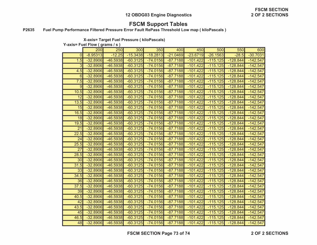
FSCM Support TablesP2635 Fuel Pump Performance Filtered Pressure Error Fault RePass Threshold Low map ( kiloPascals )
X-axis= Target Fuel Pressure ( kiloPascals)Y-axis= Fuel Flow ( grams / s )
200 250 300 350 400 450 500 550 6000 -8.95313 -12.25 -15.3438 -18.2813 -21.0469 -23.6719 -26.1563 -28.5 -30.7031
1.5 -32.8906 -46.5938 -60.3125 -74.0156 -87.7188 -101.422 -115.125 -128.844 -142.5473 -32.8906 -46.5938 -60.3125 -74.0156 -87.7188 -101.422 -115.125 -128.844 -142.547
4.5 -32.8906 -46.5938 -60.3125 -74.0156 -87.7188 -101.422 -115.125 -128.844 -142.5476 -32.8906 -46.5938 -60.3125 -74.0156 -87.7188 -101.422 -115.125 -128.844 -142.547
7.5 -32.8906 -46.5938 -60.3125 -74.0156 -87.7188 -101.422 -115.125 -128.844 -142.5479 -32.8906 -46.5938 -60.3125 -74.0156 -87.7188 -101.422 -115.125 -128.844 -142.547
10.5 -32.8906 -46.5938 -60.3125 -74.0156 -87.7188 -101.422 -115.125 -128.844 -142.54712 -32.8906 -46.5938 -60.3125 -74.0156 -87.7188 -101.422 -115.125 -128.844 -142.547
13.5 -32.8906 -46.5938 -60.3125 -74.0156 -87.7188 -101.422 -115.125 -128.844 -142.54715 -32.8906 -46.5938 -60.3125 -74.0156 -87.7188 -101.422 -115.125 -128.844 -142.547
16.5 -32.8906 -46.5938 -60.3125 -74.0156 -87.7188 -101.422 -115.125 -128.844 -142.54718 -32.8906 -46.5938 -60.3125 -74.0156 -87.7188 -101.422 -115.125 -128.844 -142.547
19.5 -32.8906 -46.5938 -60.3125 -74.0156 -87.7188 -101.422 -115.125 -128.844 -142.54721 -32.8906 -46.5938 -60.3125 -74.0156 -87.7188 -101.422 -115.125 -128.844 -142.547
22.5 -32.8906 -46.5938 -60.3125 -74.0156 -87.7188 -101.422 -115.125 -128.844 -142.54724 -32.8906 -46.5938 -60.3125 -74.0156 -87.7188 -101.422 -115.125 -128.844 -142.547
25.5 -32.8906 -46.5938 -60.3125 -74.0156 -87.7188 -101.422 -115.125 -128.844 -142.54727 -32.8906 -46.5938 -60.3125 -74.0156 -87.7188 -101.422 -115.125 -128.844 -142.547
28.5 -32.8906 -46.5938 -60.3125 -74.0156 -87.7188 -101.422 -115.125 -128.844 -142.54730 -32.8906 -46.5938 -60.3125 -74.0156 -87.7188 -101.422 -115.125 -128.844 -142.547
31.5 -32.8906 -46.5938 -60.3125 -74.0156 -87.7188 -101.422 -115.125 -128.844 -142.54733 -32.8906 -46.5938 -60.3125 -74.0156 -87.7188 -101.422 -115.125 -128.844 -142.547
34.5 -32.8906 -46.5938 -60.3125 -74.0156 -87.7188 -101.422 -115.125 -128.844 -142.54736 -32.8906 -46.5938 -60.3125 -74.0156 -87.7188 -101.422 -115.125 -128.844 -142.547
37.5 -32.8906 -46.5938 -60.3125 -74.0156 -87.7188 -101.422 -115.125 -128.844 -142.54739 -32.8906 -46.5938 -60.3125 -74.0156 -87.7188 -101.422 -115.125 -128.844 -142.547
40.5 -32.8906 -46.5938 -60.3125 -74.0156 -87.7188 -101.422 -115.125 -128.844 -142.54742 -32.8906 -46.5938 -60.3125 -74.0156 -87.7188 -101.422 -115.125 -128.844 -142.547
43.5 -32.8906 -46.5938 -60.3125 -74.0156 -87.7188 -101.422 -115.125 -128.844 -142.54745 -32.8906 -46.5938 -60.3125 -74.0156 -87.7188 -101.422 -115.125 -128.844 -142.547
46.5 -32.8906 -46.5938 -60.3125 -74.0156 -87.7188 -101.422 -115.125 -128.844 -142.54748 -32.8906 -46.5938 -60.3125 -74.0156 -87.7188 -101.422 -115.125 -128.844 -142.547
12 OBDG03 Engine DiagnosticsFSCM SECTION
2 OF 2 SECTIONS
FSCM SECTION Page 73 of 74 2 OF 2 SECTIONS

FSCM Support Tables
P2635 Maximum Engine Intake Boost curve ( kiloPascals)
X-axis= barometric pressure ( kiloPascals )40 50 60 70 80 90 100 110 1200 0 0 0 0 0 0 0 0
12 OBDG03 Engine DiagnosticsFSCM SECTION
2 OF 2 SECTIONS
FSCM SECTION Page 74 of 74 2 OF 2 SECTIONS