Embed Size (px)
Citation preview

129
12. Network Technologies for 5G This chapter describes network technologies for 5G. Based on the guiding concept
"network softwarization", which elaborates the overall transformation trend including Network Functions Virtualisation (NFV) and Software Defined Networking (SDN), technology focus area is identified as the result of study in the network architecture group of 5GMF. The brief description of the area and the associated technical issues are described in the following sections.
12.1 Technology focus area
Fig. 12.1-1 describes technology focus area of networking technologies for 5G. It is intended to guide the research and development activities to address essential issues. The results of such activities will constitute the basis for designing 5G systems. The technology focus is divided into four areas: network softwarization, network management/orchestration, fronthaul/backhaul and mobile edge computing.
Fig. 12.1-1 Technology Focus Area
Network softwarization
Network softwarization is an overall transformation trend about designing, implementing, deploying, managing and maintaining network equipment and/or network components through software programming. By exploiting the natures of software such as flexibility and rapidity, the industry is working towards for a cost-optimized and value-creating telecommunications infrastructure, which enables

130
prompt delivery of new services with lower equipment and operating expenditure. The industry effort on NFV and SDN are integral part of this transformation. The term “network softwarization” was coined by the academic community, with the aim of harmonizing a number of independent efforts in this industry. It is expected that such harmonization effort will allow operators to utilize consistent and stable foundations for realizing 5G systems.
Network management and orchestration
NFV and SDN technologies constitute the foundation for managing the life cycle of logically isolated network partitions, called “slices”. When creating a slice, the management and orchestration functions, NFV-MANO, will provide primary capabilities: select functions requested, launch them on a virtualization platform, and connect them via virtual networks created on physical infrastructure. NFV-MANO is the management and orchestration function that is being defined and specified in the Industry Specification Group (ISG) on Network Functions Virtualisation (NFV) in the European Telecommunications Standards Institute (ETSI). NFV-MANO currently focuses on a single site scenario. However, it is being extended to cover end-to-end service scenarios, in which multiple sites are connected over networks of different administrative domains.
A number of technical challenges are necessary in this area, so as to make the best use of the foundations available in the industry. It includes how to efficiently manage individual functions that constitute end-to-end service context and how to define management models to establish service level agreement when those functions are deployed in different administrative domains. Other challenges include automation and autonomy capabilities which provide easy-to-use workflow procedures for prompt delivery of services and analytics capabilities that will guide optimum placement of functions.
Fronthaul/backhaul
In order to support increasing traffic, mobile operators will need to introduce a number of small cells through the addition of base stations or remote radio heads (RRHs) operated with baseband units (BBUs). Mobile fronthaul (MFH) is a transport network connecting RRHs to BBUs and mobile backhaul (MBH) is a transport network connecting BBUs with core network functions, such as MME, S-GW/P-GW and so forth.

131
The current MFH is realized by a high speed digital link technology called common public radio interface (CPRI). The wireless signal received and transmitted by RRHs is digitized and coded with CPRI and transferred through optical fibers. For 5G and beyond, the capability of CPRI needs to be advanced so as to match the data transfer requirements, by using techniques such as, high-speed signal processing and precise clock skewing. In addition, new signal processing method and redesign of functional components among RRHs and BBUs will be required.
Considering the economics of building MFH and MBH, it is essential for mobile operators to make the best use of existing physical infrastructure. In Japan, optical fiber networks are available in most of the urban and suburban areas, while other types of networks are utilized in other counties and regions. The international standardization organization is expected to take the leadership role to establish industry-wide standards by incorporating various regional requirements on existing physical infrastructure.
Mobile edge computing
Mobile edge computing (MEC) will play a central role in order to support end-to-end quality of applications and services. In December, 2014, ETSI established an ISG on MEC. Telecom operators, vendors and service providers have been studying techniques and methodologies to distribute functions with the aim of creating open standards. MEC is expected to provide the means to address the support of latency sensitive or high bandwidth applications. Technical challenges include how to decompose functions, where to place the functions to sustain the quality and how to design edge computing platform in an economically viable manner. 12.2 Network softwarization
12.2.1 General definition
Network softwarization is an overall transformation trend about designing, implementing, deploying, managing and maintaining network equipment and/or network components. It exploits the nature of software such as flexibility and rapidity the lifecycle of network functions and services. It will enable re-design of network and service architectures, in order to optimize processes and expenditure, enable self-management and bring added values in an infrastructure.
The term “network softwarization” was first introduced at the academic conference,

132
NetSoft 2015, the first IEEE Conference on Network Softwarization. It encompasses broader ideas in the industry including Network Virtualization, NFV, SDN, MEC, Cloud/IoT technologies and so forth.
12.2.2 Network softwarization in 5G
12.2.2.1 Network softwarization view of 5G systems
The term “network softwarization” is introduced to describe the view of 5G systems with the notion of programmable software defined infrastructure.
The basic capability provide by “network softwarization” is “Slicing” as defined in [ITU-T Y.3011], [ITU-T Y.3012]. Slicing allows logically isolated network partitions (LINP) to exist in an infrastructure. Considering the wide variety of application domains to be supported by 5G systems, it is necessary to extend the concept of slicing to cover a wider range of use cases than those targeted by NFV/SDN technologies, and a number of issues are to be addressed on how to compose and manage slices created on top of the infrastructure.
Fig. 12.2-1 Network softwarization view of 5G systems
Fig.12.2-1 illustrates the network softwarization view of 5G systems, which consists
of a couple of slices created on a physical infrastructure and a “network management and orchestration” box. A slice is a collection of virtualized or physical network functions connected by links, and it constitutes a networked system. In this figure, the slice A consists of a radio access network (RAN), a mobile packet core, an UE (User Equipment)/device and a cloud, each of which are a collection of virtualized or physical network functions. Note that the entities in Fig.12.2-1 are described symbolically: links

133
are not described for simplicity. The box “network management and orchestration” manages the life cycle of slices: creation, update and deletion. It also manages the physical infrastructure and virtual resources, abstraction of physical ones. The physical infrastructure consists of computation and storage resources that include UEs/devices (e.g. sensors) and data centers, and network resources that include RATs, MFH, MBH and Transport. It should be noted that both computation/storage resources and network resources are distributed and are available for virtualized network functions wherever required.
In addition, virtualized network functions and other functions assigned to a slice are controlled by the “slice control”. It oversees the overall networked system by configuring its entities appropriately. It may include network layer control, and service/application layer control. In some cases, it makes a part of infrastructure being service-aware. It depends on the requirements presented for the networked system, for example, a slice to provide the support of information centric networks (ICN).
Orchestration is defined as the sequencing of management operations. For example, a customer may send a request to the “network management and orchestration” box with their own requirements of an end-to-end service and other attributes related. The request is handled in the box and network programmability functions, if they exist, in the fronthaul/backhaul, core networks, software-defined clouds and mobile edge computing. This involves,
• support for on demand composition of network functions and capabilities and
• enforcement of required capability, capacity, security, elasticity, adaptability and flexibility where and when needed.
Step 1: Creating a slice
Based on a request, the “network management and orchestration” creates virtualized or physical network functions and connects them as appropriate and instantiate all the network functions.
Step 2: Configuring the slice
The slice control takes over the control of all the network functions and network programmability functions if they exists, and configure them as appropriate to start an end-to-end service.

134
12.2.2.2 Horizontal extension of slicing
In 5G, to satisfy end-to-end quality is an important requirement. Especially as wireless technologies are expected to advance, networking technologies should support as appropriate to sustain end-to-end quality of communications. Therefore, it is natural to consider extending the slicing concept to cover end-to-end context, i.e., from UE to Cloud. Issues in extending slices have to then be addressed, not only the software defined infrastructure in a limited part of a network, but also the entire end-to-end path.
The scope of the current SDN technology primarily focuses on the portions of the network such as within data-centers or transport networks. In 5G, it is necessary to consider end-to-end quality. Therefore, there exists a gap between the current projection of SDN technology development and the requirement for end-to-end quality. It is desired that an infrastructure for 5G will support end-to-end control and management of slices and the composition of multiple slices, especially with consideration of slicing over wireless and wireline parts of end-to-end paths.
Fig. 12.2-2 shows the breakdown of the end-to-end latency in the current mobile network. This figure implies that the network architecture needs to allow latency-aware deployment of network functions and services in order to satisfy end-to-end latency requirements.
Fig. 12.2-2 Breakdown of end-to-end latency of the current mobile network
3GPP carried out latency studies for 3G, which are documented in specifications TR
25.912, TR25.913, TR36.912 and TR36.913. 3GPP has carried out studies for future network service requirements, which are documented in TR22.891. Operators are building LTE networks to meet the latency budget provided in the 3GPP specification.

135
Latency studies carried out on many LTE deployed networks demonstrate that the 3GPP specifications provide adequate guidelines. Actual LTE network performances varied, however, due to a variety of variables as well as adjacent ecosystems.
For 5G, an extensive latency study should be carried out in order to provide guidelines for a number of latency-critical services. In order to structure the latency study framework, it is suggested to use breakdown of latency according to Fig. 12.2-2.
12.2.2.3 Vertical extension of slicing (Data plane enhancement)
5G systems may support various communication protocols, even those that have not yet been invented, for services such as Internet of Things (IoT) and content delivery provided by information centric networking (ICN) and content centric networking (CCN). Advanced infrastructure may need the capability of data-plane programmability and associated programming interfaces, which we could call the vertical extension of slicing. The current SDN technology primarily focuses on the programmability of control-plane, and only recently the extension of programmability to data-plane is being discussed in the research community and in ITU-T SG13 without well-defined use cases. For 5G, there are several use cases for driving invention and introduction of new protocols and architectures especially at the edge of networks. For instance, the need for redundancy elimination and low latency access to contents in content distribution drives ICN at mobile backhaul networks. Protocol agnostic forwarding methods such as protocol oblivious forwarding (POF) discuss the extension to SDN addressing forwarding with new protocols. In addition, protocols requiring large cache storage such
as ICN needs new enhancement. A few academic research projects such as P41 and FLARE 2 discuss the possibility of deeply programmable data-plane that could implement new protocols such as ICN, but there is no standardization activity to cover such new protocols to sufficient extent. Therefore, there exists a gap between the
1 Pat Bosshart, Dan Daly, Martin Izzard, Nick McKeown, Jennifer Rexford, Cole Schlesinger, Dan
Talayco, Amin Vahdat, George Varghese, David Walker, “Programming Protocol-Independent Packet
Processors”, http://arxiv.org/abs/1312.1719
2 Nakao, Akihiro. "Software-defined data plane enhancing SDN and NFV." IEICE Transactions on
Communications 98.1 (2015): 12-19.

136
current projection of SDN technology development and the requirements for deep data-plane programmability. The infrastructure for 5G is desired to support deeper data-plane programmability for defining new protocols and mechanisms.
12.2.2.4 Considerations for applicability of softwarization
In general, not every component of infrastructure may be defined by software and made programmable, considering the trade-off between programmability and performance. Therefore, it is necessary to clearly define the role of hardware and software according to the potential use cases when softwarizing infrastructure.
SDN is primarily motivated by reduction of operating and capital expenditure and flexible and logically centralized control of network operations. Operators might be motivated to softwarize everything everywhere possible to meet various network management and service objectives. In addition, traffic classification is often per flow basis.
In 5G, some applications have stringent performance requirements such as ultra-low latency and high data rate, while others may require cost-effective solutions. A range of solutions exists from application driven software-based solutions executed on virtualization platform with hypervisor, container or bare metals, to complete hardware-assisted solutions. The former may need performance enhancement enabled by hardware-assisted solutions, while the latter may be facilitated by software-based solutions. The infrastructure for 5G may need to support traffic classification performed not only by flow-basis but also by other metrics and bundles such as per-device and per-application basis so as to apply software/hardware based solutions appropriately for individual use cases. Therefore, there exists a gap between the current projection of SDN technology development and the requirements for applicability of softwarization.
12.2.2.5 End-to-end reference model for scalable operation
Softwarized systems should have sufficient levels of scalability in various aspects of functions, capabilities and components. Firstly, the target range of the number of instances should be considered, e.g. service slices to be configured and to be in operation concurrently. The number of clients and service providers accommodated by each service slice is also an important metric for the practical deployment of the systems. The main constraints for scalability would be the dynamic behavior of each slice and control granularity of physical resources. The communication session established by mobile

137
packet core, however, would be challenging, because it requires a dedicated system for such an extraordinary multiple-state and real-time control, especially for mobility handling. The coordination and isolation between these systems should be clearly defined. Nevertheless, scalability for other types of sessions would also be an issue concerning architectural modelling, including application services, system operation or advanced network services.
In addition to the dimensions and dynamics of the systems, further research is required from the perspective of resiliency and inter-system coordination. For resiliency, some new aspects might be considered other than traditional mean-time-between-failure (MTBF) type faulty conditions. In case of disaster, for example, fault localization, analysis and recovery of softwarized systems could be more complicated. Traditional operation architecture also finds it difficult to cope with misbehaviors caused by human factors because of the indirectness arisen when operating softwarized systems.
The inter-system coordination architecture should be clearly structured and modelled for efficient standardization and for scalability evaluation of softwarized systems. There might be two categories of the coordination, namely horizontal and vertical. The horizontal coordination is for between slice, cloud systems, and UE; in other words, the end-to-end system coordination. Vertical coordination can be distinguished in two ways. One way is for slice and service provider through APIs and the other way is for virtual and physical resource coordination aimed to efficient resource handling through policy and analytics.
In summary, softwarized systems should have sufficient levels of scalability as follows:
- The number of instances/service slices to be supported - Series of capabilities provided by service slices - The number of service sessions to be handled concurrently - Dynamic behavior of instances and slices - Granularity of resource management, especially for policy control and/or
analytics - Resiliency for various faulty conditions - Intra-slice coordination among end-to-end resources - Inter-slice coordination, specifically with various external systems.
Intensive studies are required on both the dimension and the dynamic behavior of

138
softwarized systems, since such systems will have an enormous number of instances and their reactions are not easy to extrapolate from the current physical systems.
Virtual resource handling must be an essential part of the scalable and novel operation architecture, which potentially improves conventional network operations and possibly even up to the level of supporting disaster recovery by using network resiliency and recovery of/with the systems both in a single domain and in multiple domains.
The end-to-end quality management is a key capability required for 5G. However, this capability will be established on the complex interaction among softwarized systems including UEs, cloud systems, applications and networks. An appropriate end-to-end reference model and architecture should be intensively investigated for such complex systems. 12.2.2.6 Coordinated APIs
It may be useful to define APIs so that applications and services can program network functions directly bypassing control and management to optimize the performance, e.g., to achieve ultra-low latency applications.
Discussions on the capabilities of the programmable interface should be objective-based: for example, accommodating a variety of application services easily, enabling higher velocity of service deployment and operation and efficient physical resource utilization. Users or developers who utilize the APIs can be categorized according to their roles. Application service providers will enable value added services over the end-to-end connectivity through the APIs. Advanced network service providers will add some sophisticated functions to communications sessions, such as security and reliability, in order to facilitate faster application service deployment by the aforementioned application service providers. Network management operators will also utilize the APIs for more efficient and agile resource handling.
Information modelling should be the most significant issues for API definitions. It should include virtual resource characteristics, relationships between various resources, operational models, and so on. Levels of abstraction should be carefully investigated, so that the model and APIs should be human-readable and machine/system-implementable at higher performance simultaneously. Since considerations on software development methodologies will have an impact on the development model, the choice of the proper methodology for each capability will be

139
important. The system control and coordination architecture is another issue that will affect the
achievement of scalable and agile APIs. Not only the traditional provisioning/configuration or distributed control of networking systems, automatic and autonomic system control should be the main target. The closed loop control architecture might be the most innovative enhancement from the traditional networking systems even for the APIs.
The robustness and fault tolerance are absolutely necessary for open systems controlled through the APIs by various providers. Isolation over virtual resources should be carefully structured with the APIs’ functionalities and constraints.
In summary, discussions on the programmable interface capabilities should embrace: - Level of abstraction sufficient both for system operations and for
customization of the capability provided by the interfaces; - Modelling for virtual/abstracted resources in a multiple-technology
environment; - Ease of programming for service and operation velocity; - Technologies for automatic and/or autonomic operations; - Provisioning of classified functional elements suitable for a range of system
developers such as supplication service providers, network service providers, and network management operator.
12.2.3 Information Centric Network (ICN) enabled by network softwarization
12.2.3.1 General Characteristics
a. Overview One of the aims of 5G is the provision of the emerging network paradigm which fits
social requirements. ICN is a promising candidate, with a variety of R&D activities ongoing worldwide. ICN has several merits, including:
1. Server location independent access by contents name 2. Traffic reduction by in-network caching 3. Easy provisioning of in-network data processing 4. Contents security 5. Robustness to network failures by multi path routing
Details of these aspects are described below. This paradigm, however, adopts a new data forwarding mechanism different from the
current Internet. Therefore, it is necessary to have data-plane programmability.

140
b. Contents/service delivery by its name The prime difference between ICN and the current internet is how content is accessed.
Content is accessed on the Internet through knowing where the content server is located on the network. ICN, on the other hand, content is accessed by submitting a request of the name of the content is on the network. The network will then route the request to the appropriate network node which is storing or caching the named content. The capability to access content by finding “named content” is the basis of ICN, by which the point where named content is stored dynamically moves to the node where the content is most frequently requested and therefore is more efficiently served to the end-user. This can also apply to in-network data processing services. Accessing named content also makes it easier to support consumer mobility by making the ability to serve content more efficient, as well as improving human readability of content requests. c. Traffic reduction by in-network caching
Another feature of ICN is in-network caching. ICN network nodes are equipped with a content cache server which caches content going through a particular node. The server will then autonomously select which content to cache based on the need of the users accessing the node. Generally, despite different use-cases, content will generally move towards the network edge node where the specific named content is frequently requested. Once the most popular content is cached at the network edge node, subsequent content requests will be served at the particular network edge node, with future communication being terminated at this edge, resulting in a total reduction of the network traffic and lessening the overall server load. d. In-network data processing
In-network data processing will provide network nodes to do network wide data processing and provide application services on network nodes. The current configuration will need a basic structural change to handle the increase of video traffic and the expansion of IoT as well as to provide shorter response times. Currently data processing is done at a remote data center and the network functions only as a data pipe. In 5G, data processing for application services will be provided with the aim of reducing network congestion as well as shortening response time when necessary. Two typical examples of in-network data processing are ICN, which reduces traffic congestion and response time through the use of a network cache, and edge computing, which provides data processing and service provisioning at the network edge. In-network processing can be considered generally an expanded form of edge computing, where data
141
processing and service provisioning will be provided dynamically any place on a network that is appropriate. Due to the dynamic nature of service and data processing points, ICN’s basic mechanism of accessing requested content by name rather than location is especially suitable to provide in-network data processing. Edge computing also is efficient in terms of shortening response times and reducing network congestion when the target data for computing is close to an edge node area. Some IoT use-cases will, however, have target data needed for processing across many edge node areas, therefore the inner node of a network will be more appropriate for processing. Another example is on-path data processing, which data processing is applied in tandem on a transmission path. This is frequently used in big data processing. There are also some use-cases in which the inner network node is better suited to perform data processing, for example when users for a particular service are few in number and yet distributed across several edge nodes. e. Content security
In some ICN architecture such as CCN and NDN, content security is provided as a basic function. Since security is a key concern in several systems like content delivery and IoT, having a built-in security mechanism is very attractive point of ICN. f. Robust to network failure by multi-path routing
To enable the content access by name, ICN routing/forwarding is capable of multi-path routing, because the contents once cached in certain node will not be available at the next chance. In ICN multi-path routing, when the response does not come back from the direction the interest is sent out, the node will automatically issue the same request to another direction. This mechanism is very helpful when the part of the network failed down such as the disaster case, and makes the network robust to the failure. 12.2.3.2 Applications of ICN
a. Networking in a disaster area This service scenario describes ICN as a communication architecture which provides
an efficient and resilient data dissemination in a disaster area. A provider using ICN will be able to directly disseminate emergency data to specific
individuals or groups. In this use case, the consumers in advance will express their interest in a specific type of emergency data and information, which ICN will deliver when available. Providers will also be able to directly disseminate emergency data to its
142
users in case of an emergency regardless of any prior requests for this service, as well. A provider can push emergency data to the cache or storage of ICN nodes, and then
the ICN nodes can indirectly deliver the emergency data from their cache or storage to specific individuals and groups as well as to a larger population using the network on a case-by-case basis.
ICN nodes have sufficient storage capacity and so they can hold emergency data for a long time. Both providers and consumers can use the ICN storage system as intermediate devices to share any emergency data with others during a disaster period.
Providers will be able to efficiently and resiliently disseminate emergency data in a disaster area due to the forwarding and caching functions of ICN, in which emergency data is forwarded to an intermediate ICN node where the data is kept (cached) first and then sent to the final destination or to another intermediate ICN node. The caching data can be served for other consumers (efficient data dissemination) even when the original provider is not available due to a temporal network partition (resilient data dissemination).
A consumer can retrieve emergency data even from an intermittently connected network during a disruption or disaster period. ICN follows a receiver (consumer)-driven communication model where receivers can regulate if and when they wish to receive segments of data, and so continuous data retrieval from multiple ICN caching points is possible without regard to end-to-end session.
Operators will benefit from the reductions in system construction costs related to protecting their networks in case of a disaster. Due to name based communication, there is no clear, functional boundary between the network and end devices in ICN. This means ICN nodes can act on behalf of end devices by recognizing and responding to user requests. For example, all ICN nodes will be able to respond to all consumers using its storage capability to share information in a disaster area. This will be a particularly useful feature at times when it is impossible to predict which parts of a network will not be accessible during a disaster. b. Advanced metering infrastructure (AMI) on a smart grid
This service scenario involves smart meters, communications networks and data management systems that provide two-way communication between utility companies and their customers. Customers will be given assistance through devices such as in-home displays and power management tools. On the communication network, ICN nodes can be installed in order to keep a copy of this data in its cache, which can then be

143
used to present the data in a desired format for the convenience of both the consumer as well as the utility company. The ability to quickly retrieve use pattern data of a particular service is very important in order to efficiently plan and consume services provided by utilities to consumers.
By using the ICN nodes in the network, efficient resources usage and effective load control is possible. Besides an ICN approach for AMI systems in smart grid, they can efficiently control network congestion, support mobility and ensure security.
Since with ICN it is possible to secure data itself, customer will feel more comfortable with the smart grid infrastructure based on the ICN. Furthermore, the operator (utility company) can manage the data more cost-effectively. It also adds value in the scalability issue. c. Proactive Caching
This service scenario involves people who will access the internet by through their portable device, such as a smartphone or laptop, while passengers of a moving vehicle, such as trains, cars and buses. A certain passenger wants to watch a video-on-demand on her smartphone. If this passenger is on a commuter train, the desired video will be proactively cached in every train station's ICN node according to the scheduler, which decides how much video content should be proactively cached according to video and transportation information. If the user is a vehicle passenger, such as a car, the vehicle mobility information, accessed from the navigation system, can be used to choose an ICN node where content/video will be cached proactively.
The quality of video delivery can be significantly improved by using proactive caching integrated with ICN nodes. Since an ICN node fetches a data object in advance, data objects requested by the mobile user will be immediately available after changing the Point of Attachment. The delay will be minimized due to the reduction of number of hops taken during data transmission. In addition, since the ICN node will maintain a cache of a particular data object, all subsequent requesters of the same data object will reuse the data already cached by the ICN node.
Network operators will benefit, as well. First, bandwidth consumption will decrease due to caching and data-reuse. Second, energy consumption will be reduced since data objects accessed from ICN nodes through Wi-Fi, reducing traffic on 3G/4G networks. The reduction of transmission delays will also allow providers to offer enhanced user experiences for their customers.

144
12.2.3.3 Migration scenario
5G will co-exist with legacy network equipment and be compatible with existing network technologies. In other words, it should work in a hybrid manner: it may be composed of classical physical network appliances and softwarized appliances during the intermediate phase towards full deployment. Therefore, migration from the starting network to the target one will gradually be accomplished by using a hybrid deployment model, as shown in the following three-steps-migration path:
Fig. 12.2-3 Phased Migration
Starting network: The starting network phase utilizes current and state-of-the-art network technologies
(existing technologies), including LTE and IP-based networks. Phased deployment (intermediate phase): The benefit of this model of deployment during the migration intermediate phase is
all end-to-end resources can still be maintained through conventional communication means in order to communicate with each other. As a result, this mechanism enables migrated end-to-end resources that have been deployed in conjunction with existing devices. It enhances the migration process feasibility by enabling both the gradual deployment of 5G while maintaining current communication models simultaneously during intermediate period.
The requirements for 5G migration are as follows: 5G is a foundation of future services and having a mechanism to smoothly evolve to
the one which is under discussion in ITU-T SG13/Q15; Migration scenarios from the early stage of 5G; Locality based service provisioning mechanisms and architecture: mobile edge

145
computing, a major topic of interest in 5G discussions, and local area computing are examples;
Possibilities of the in-network data processing/service provisioning capability, where each network node carries out some data processing and service provisioning, a feature especially useful for the efficient management of IoT devices and big data.
Adoption of emerging network technology. Possible technological directions include: Application of network softwarization as a core technology of 5G, such as SDN and
NFV; Adoption of multiple logical networks (slice), each having different architecture that
fits to the services provided on the slice. Candidates include: IP , ICN, IoT, and low latency;
Having a clear API to provide for the development and distribution of a variety of applications and services.
Moreover, 5G will need to provide in-network data processing capabilities, whereby each network node carries out some data processing and service provisioning. This feature will allow 5G to handle IoT devices and big data efficiently. Target network:
This will also benefit network operators. First, the bandwidth consumption will be low due to caching and data-reuse. Second, energy consumption will be reduced by accessing data objects from the ICN node through Wi-Fi, reducing the 3G/4G traffic. Since the transmission delays will be minimized, network operators will be able to provide an enhanced user experience, as well.
12.3 Management and Orchestration
12.3.1 Overview
12.3.1.1 Management and orchestration technologies
Network management will have a more important role than today in order bring about the full capabilities and services that 5G can provide. In this context, the scope of management and orchestration should cover mechanisms of providing application-driven flexible network as well as managing FCAPS (Fault, Configuration, Accounting, Performance, and Security). In addition, the aforementioned mechanisms will need to be able to provide non-continuous service based upon user needs.
In the following section (i.e., 12.3.2), approaches to these mechanisms are discussed.
146
12.3.1.2 Challenges and requirements
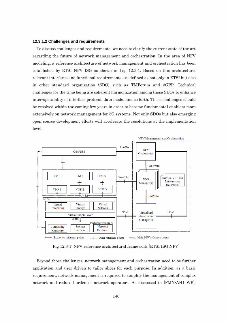
To discuss challenges and requirements, we need to clarify the current state of the art regarding the future of network management and orchestration. In the area of NFV modeling, a reference architecture of network management and orchestration has been established by ETSI NFV ISG as shown in Fig. 12.3-1. Based on this architecture, relevant interfaces and functional requirements are defined as not only in ETSI but also in other standard organization (SDO) such as TMForum and 3GPP. Technical challenges for the time being are coherent harmonization among those SDOs to enhance inter-operability of interface protocol, data model and so forth. Those challenges should be resolved within the coming few years in order to become fundamental enablers more extensively on network management for 5G systems. Not only SDOs but also emerging open source development efforts will accelerate the resolutions at the implementation level.
Fig 12.3-1: NFV reference architectural framework [ETSI ISG NFV]
Beyond those challenges, network management and orchestration need to be further
application and user driven to tailor slices for each purpose. In addition, as a basic requirement, network management is required to simplify the management of complex network and reduce burden of network operators. As discussed in [FMN-AH1 WP],

147
analyzing the large amount of management data (e.g., statistics, syslogs, events, alarms) for preventing serious event and introducing more distributed way of processing management data will be an additional requirement toward 5G.
12.3.2 Approaches for 5G network management
12.3.2.1 Flexible network for optimal performance and resources
Background and Motivation Future mobile networks are expected to provide connectivity with a vast variety of
applications and services requiring a wide range of levels of quality in terms of respective performance.
For example, some types of unique variations will be required in following use cases: - Super high data rate services (e.g. future video applications) - Ultra-low latency services (e.g. tactile and quick response interactive
applications) - Massive number of connections (e.g. M2M/IoT sensors and actuators) - Super high quality of mobile services (equivalent quality to fixed line services) - Super reliable data communications (e.g. autonomous driving, life-line
tele-communication) Data traffic varies across a wide range in the use-cases, depending on time (e.g.
daytime vs. midnight), location (e.g. indoor vs. outdoor), and the usage environment. Scenes of dynamic traffic change can be found in situations such as the dynamic
hotspot inside a stadium during a sporting event, a concert hall, a station platform, an ongoing festival, and emergency calls in disaster scene and so forth.
The following chart shows the actual traffic volume of broadband Internet data (e.g. DSL, FTTH) measured in Japan by the MIC from 2009 to 2014. While data traffic is increasing every year, the data amount varies in a range of four times or more depending on the time of day and the day of the week as observed in statistics.
Such a behavior of traffic variation is also the case in the mobile application data as illustrated in Fig.12.3-2 below.

148
Fig. 12.3-2 Traffic fluctuation of Internet user data in Japan [MIC]
.
(a)
(b) Fig. 12.3-3 Diverse capabilities depending on applications, and on the
time/location domain [ARIB]
149
This variation depends on the service application such as video streaming, virtual reality, M2M, and autonomous driving, as shown in Fig. 12.3-3 (a). And it should be noted that the user service does not always require a higher level of performance as presented in Fig. 12.3-3 (b).
Similar views of the application dependency can be found in the Rec. ITU-R M.2083-0, where enhancement of key capabilities is described as the targets for IMT-2020.
Table 12.3-1 Key capabilities and the extreme target
in IMT.VISION, ITU-R Rec.2083-0 (09/2015)
Key Capabilities Extreme Target
Peak data rates 20 Gbps
Latency (air interface) 1 ms
Connection density 106 /km2
Mobility 500 km/h
This table provides the future visions of key capabilities of IMT-2020 from a radio
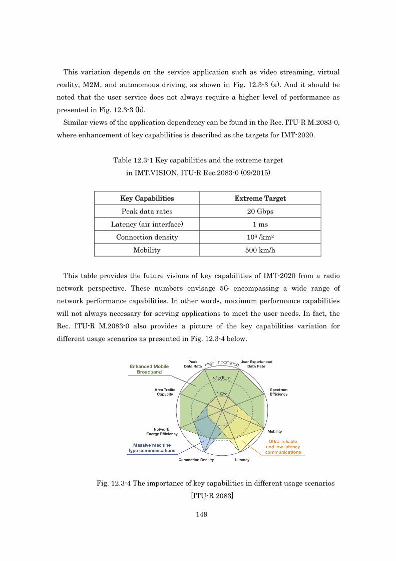
network perspective. These numbers envisage 5G encompassing a wide range of network performance capabilities. In other words, maximum performance capabilities will not always necessary for serving applications to meet the user needs. In fact, the Rec. ITU-R M.2083-0 also provides a picture of the key capabilities variation for different usage scenarios as presented in Fig. 12.3-4 below.
Fig. 12.3-4 The importance of key capabilities in different usage scenarios
[ITU-R 2083]

150
The above chart presents three types of usage scenarios below. Enhanced Mobile Broadband Ultra-reliable and low latency communications Massive machine type communications
Depending on the service type, the required level of capability varies in a scale by several magnitudes to the 10th index power for each capability.
Because of these aspects of future network services, 5G should offer flexible virtual network capabilities to meet specific service demands using the network resources obtained from the infrastructure facilities and physical resources. Key requirements for the virtual network may be identified as: guarantee quality and performance in accordance with the service level
requirements; provide specialised handling of traffic flows in the network segments; open and programmable configuration for specialised traffic processing; efficient sharing of network resources pooled in the infrastructures and the
physical domains; Given these network capabilities, the network structure has to be scalable enough to
be able to cope with flexibility and agility with the changes of traffic loading in order to save operational costs, for example power, link usage, and at hardware facilities.
Consequently, in order to realize the service-oriented optimized network, a virtual network and functional nodes on the associated topology, protocols, and data transport mapped on a specific slice need to be configured flexibly depending on the application type, service profile, operation environment and service quality by means of programmable controllers organized by the management entity. The operation of controllers together with the network resources management are to be activated, coordinated, and organized comprehensively in an intelligent manner by the network orchestrator. Research and Future Challenges concerning the introduction of Flexible Networks
The following research has been identified as necessary for the introduction of flexible networks to be able to achieve optimal performance and resources utilization;

151
Study 1: Virtual network structuring with programmable control under the management and orchestration
5G should be designed considering the factors discussed above. In addition, the associated control/management software needs to be developed to organize user data transportation and processing, in the distributed functional nodes on the network slices. This technology should also include developing mechanisms to virtualize network functions and relocate as appropriate for flexible use.
In order to introduce the service-oriented network, a virtual networking, with optimal topology, functional nodes, protocols, and data transport paths need to be configured flexibly in a suitable way to the application type, service profile, device environment and the service demand under programmable controllers coordinated by the management entity. Those operations along with the network resources are to be activated, managed, and organized comprehensively in an intelligent manner by a unified orchestrator.
Smart network concept with the virtual network slices and the associated management and orchestration are illustrated in a sketch below to achieve optimal performance with efficient use of network resources.
Fig. 12.3-5 Conceptual view of flexible smart network
5G should be designed by considering the factors below. Challenges:
Flexible, scalable and dynamic network building Capability and suitable QoE provision for diverse service requirements

152
Autonomous network organization with intelligence Approaches: Organization and optimization of the virtual network slices and network resources Capability of demand based policy execution Deep learning with autonomous analysis
For these purposes, intelligent control/management software needs to be developed to
organize user data transportation and processing, in the distributed functional nodes on the network slices. This technology should also include developing mechanisms to virtualize network functions and to relocate network resources as appropriate for flexible use.
Study 2: Resource Management for the service profiles using pooled resources
Mobile network resource management in the flexible service-oriented architecture may be driven by having with three aspects below:
Software defined topology: Determination of the logical data plane topology for a given service consisting of the selected physical network nodes. Different services may need different functions as defined by service function chain and the physical nodes where functions need to be instantiated in this logical topology.
Software defined transport and resource allocation: This is the step of determining physical transport paths and the required resources in these paths for the data flows on the data plane, once the logical topology is determined. This would require traffic engineering to establish a reasonable link loading balance and node resourcing (e.g. processing, energy).
Software defined protocol: This is the step of determining the end-to-end (e.g. including RAN, Fronthaul/Backhaul, Core network, for example) data plane transport protocols under a software based management plane and control plane. This includes the establishment of the protocol stack and adjustment of the logical functional units depending on the application type, the expected QoE, and the physical recourse mapping.
Fig. 12.3-6 represents an example of logical structure of flexible mobile network.

153
Fig. 12.3-6 Flexible mobile network – a logical structure
With the structure of Fig. 12.3-6, some capabilities should become available for intelligent and elastic network realization as follows: Scalable network control for Dynamic Hot-spot with
Time-variant/Location-variant data calls and the traffic. Service-oriented QoE with optimal set of Throughput, Latency, Connectivity,
etc. for diverse applications. On demand based network functional nodes application for different type of
network services. Contingency networking by the flexible routing path against unpredictable
network failures. Energy saving with the optimal set of resources by the resource management
and orchestration. CAPEX/OPEX reduction for the network operators, due to efficient utilization
of the minimal set of hardware.
Functional view of Flexible Networking Following note further describes how the key entities (i.e. Management &
154
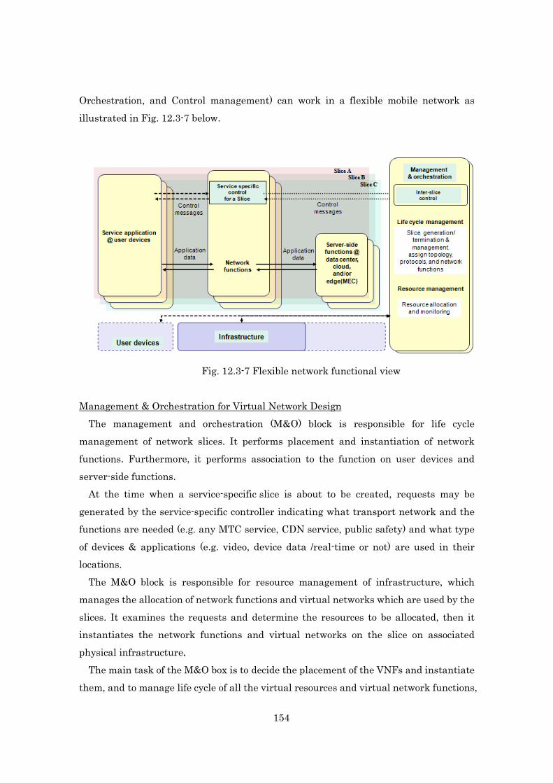
Orchestration, and Control management) can work in a flexible mobile network as illustrated in Fig. 12.3-7 below.
Fig. 12.3-7 Flexible network functional view
Management & Orchestration for Virtual Network Design The management and orchestration (M&O) block is responsible for life cycle
management of network slices. It performs placement and instantiation of network functions. Furthermore, it performs association to the function on user devices and server-side functions.
At the time when a service-specific slice is about to be created, requests may be generated by the service-specific controller indicating what transport network and the functions are needed (e.g. any MTC service, CDN service, public safety) and what type of devices & applications (e.g. video, device data /real-time or not) are used in their locations.
The M&O block is responsible for resource management of infrastructure, which manages the allocation of network functions and virtual networks which are used by the slices. It examines the requests and determine the resources to be allocated, then it instantiates the network functions and virtual networks on the slice on associated physical infrastructure.
The main task of the M&O box is to decide the placement of the VNFs and instantiate them, and to manage life cycle of all the virtual resources and virtual network functions,

155
which are used by these slices. During the service specific slice creation process, some requests may be generated by
the specific service provider indicating what service functions are needed (e.g. any MTC service, CDN service, public safety) and what type of devices & applications (e.g. video, device data /real-time or not) are used in their locations.
Having with those formations, a decision of performance optimization need to be taken based on the network analysis as for where to place these functions in the virtualized infra-structure for providing best performance for the service. As a result of this designing process, the software-defined Topology, Protocol, Resource allocation, and Data processing are configured on each of slice.
Once it is decided, then the management entities in the O&M instantiates the virtual functions on the slice in the associated physical nodes of infra-structure.
In addition, given the result of network analysis for performance optimization, the software-defined protocols, resource allocations, and data processing are configured on each slice. Scalable Management for Network Resource Control and Service Quality
Management of mobile network resources (e.g. functional node, anchoring node, access network, MFH/MBH elements, transport lines, spectrum-/time-/power-domain resources) for providing a wide range of connectivity services is a task of the control plane which enables the optimal virtual network operation. The control plane should interface with data plane via a control interface to negotiation requirements per the service/application/virtual operations, and the interface with data plane also provides w instructions for resources to be allocated for a particular service. A Common Control Manager & Service specific Control Managers
Service-specific controller for each application is allocated on each slice. Different application services may have different requirements which request different types of functions and resources (physical and virtual) and topologies to be instantiated and different configurations to be maintained during their life time.
Inter-slice manager coordinates service-specific controllers for slices and manages a common control functions in the Management and Orchestration block. It interfaces with service-specific controls to perform life cycle management and resource management of slices.
While a service specific controller may track authentication of its service application, a physical device may be tracked by the management and orchestration block in some

156
way as a particular device may be connected to multiple slices simultaneously. Control and data plane functions specific to each application are allocated on each
slice as different parts of the network because different services may have different control functions. These functions may be instantiated at different physical nodes and the virtual topologies might be quite different.
There should be an entity which co-ordinates those individual control functions, while managing a common control function, on management plane. That entry may contain a common Connectivity Manager (CM) and a common customer Service Management.
A common CM may also perform certain functions, even if a user is attached to only one slice. Examples include:
• When a user first sends an attach request – it has to first go to Common CM, then forward to specific slice CM;
When some request messages are made where the user is located (e.g. paging), the requests first come to the Common CM, since other entities may not know to which slice the UE belongs.
A service specific CM may track UE’s relative location and authentication. A device may be connected to multiple slices simultaneously. These may be tracked by a common CM on the management plane. Subscription management of the devices may be conducted by the common CM, and the session request for devices may send from the common CM to individual CMs.
12.3.2.2 Application-driven network configuration management
Scope Current mobile network mainly deals with the Internet access from smart phones and
feature phones. However, it is presumed that services provided over 5G, including IoT/M2M, will have different requirements for the network. These requirements could include latency, bandwidth, communication frequency, communication topology, and security needs. Therefore, network management on 5G systems will be needed to manage physical and virtual networks accommodating services that will have various requirements. Challenge
Challenges are -To improve QoE for each service with minimum network infrastructure -To provide very low latency services
157
Approach In-network application processing
Each service provided over 5G will have different characteristics. Some real-time services such as Augmented Reality (AR) and ITS require that networks provide low-latency communication between IoT devices and application servers. Because latency between them largely depends on the distance between them, it is efficient to locate application servers near devices. Mobile edge computing (MEC) is one of such solution. Other services deal with a large amount of data raised from sensors causing high traffic to the core network. For such services, a part of applications can be located on MEC and it executes some pre-processing function to reduce the traffic between MEC and application servers through the core network. Dynamic application allocation in the network based on service requirements
Each service consists of one or more applications. To improve QoE for each service with a minimum network infrastructure, applications related to the service should be located in 5G systems appropriately. When a new service is installed, dynamic application-allocation function locates each application on appropriate computing resources such as base stations, network nodes, servers based on the requirements from the service. Dynamic network resource allocation based on service requirements
Each service will require network functions and resources such as mobility, security and transport. To improve QoE for services with minimum network infrastructure needs, the appropriate network functions and resources should be allocated for those services. When a new service is installed over 5G, dynamic network-resource-allocation function creates a new virtual network, a ”slice”, for the service and allocates appropriate network functions on the slice based on the requirements from the service. Dynamic network-resource-allocation function may also create a new slice by combining existing slices if they can be reused. Dynamic network-resource-allocation reallocates the network functions and resources on the slice when requirements from services are changed by the environmental reasons for example the increase of users and traffic. Interworking between network function allocation and application allocation
The location of applications on the network affects the allocation of network functions. When a user application runs on a base station for instance, 3GPP Evolved Packet Core (EPC) Gateway function should be allocated at the same base station. The EPC gateway function terminates the tunneling protocol against user equipment, so that applications

158
allocated in the base station can handle the data from the user equipment. Therefore, the service management and the network management need to be coordinated each other.
Fig. 12.3-8 The overview of Application-driven network configuration management.
Various services like enterprises, ITS, healthcare run on 5G. Since each service has
different requirements, the network management (shown on the right side of the figure) sets up virtual network and the service management allocates applications realizing the service on a virtual network based on its requirements as necessary. The service management and the network management collaborate each other to provide the service appropriately and efficiently.
12.3.2.3 Forward to providing service function in network from data-transmission
network
The next generation network needs to accommodate diversified application services and meet various requirements from them. For example, one application service would demand large bandwidth dynamically. Another application service would be sensitive about end-to-end data transmission time. In this sense, customized resources are needed for each application. While resource management becomes more complex as resource usage is customized depending on the needs of each application, reducing communication data produced by MTC/IoT object could conserve a large amount of resources, as well. In order to meet these requirements, the next generation network

159
needs to create various service functions. The following are the challenges for realizing this. Challenges On-demand application-driven configuration
Application services provided by the network have become varied, and conditions of network resources requested by them have also diversified. In addition, new application services are dynamically created and provided using a virtual machine. Therefore, network resources are needed to be configured dynamically by the application services. Data processing network for MTC/IoT
In order to accommodate vast amounts of Machine Type Communication (MTC) or Internet of Things (IoT) devices, the network needs to handle a large number of varied data flows. However, MTC/IoT devices can generate a large amount of data and may cause degradation of data transmission quality due to network congestion, etc. Therefore, the amount of data needs to be reduced or transformed into statistics information by data processing inside the network. Complex and virtual network management
Conventionally, one application service is provided to many users in the same quality. However, the preferences and environments of users are typically different. Providing a customized service environment to each user using virtually separated network resources is important. The management of multiple virtualized networks is complicated, however, so management of virtual and complex networks is needed. End-to-end experience quality management
Lately, quality of service is evaluated based on user experience since the quality felt by people is not the same as the data transmission quality. In addition, end-to-end data transmission is done through multiple networks including wireless and wired networks, and evaluation scheme for heterogeneous networks is also an issue. Therefore, management to guarantee end-to-end experience quality is needed. Approach
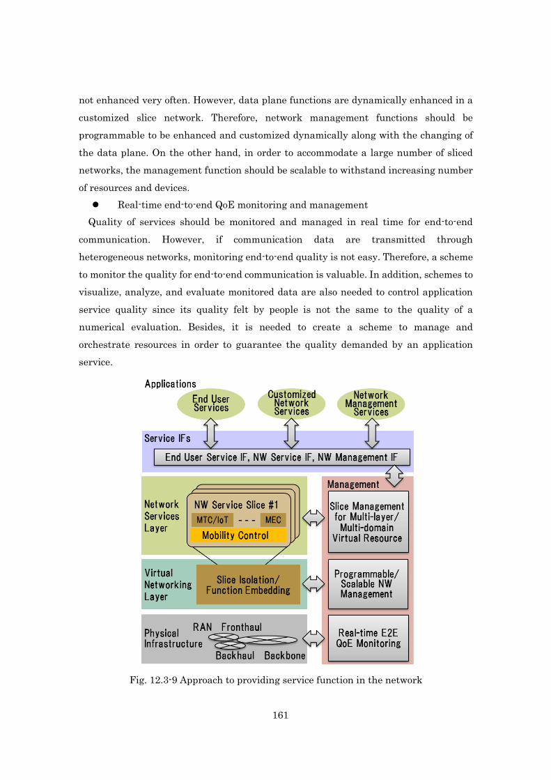
In order to address above challenges, an establishment of a framework to provide customized service functions in the network is important. Fig. x shows an overview of the framework that is composed of three resource-management layers and two resource-management components.
The three resource-management layers consist of a physical infrastructure layer, a virtual networking layer, and a network service layer. The physical infrastructure layer consists of various resources such as a radio access network, fronthaul/backhaul

160
network, backbone network resources and so forth. The virtual networking layer consists of logically integrated resources and their management functions to create multiple slices that are composed of multiple resources that are isolated between them. The network service layer consists of multiple network service slices that are composed of MTC/IoT resources, mobile-edge computing functions, mobility control functions, and so forth.
On the other hand, two resource-management components that are the keys to providing service functions in the network consist of service interfaces and management functions. These services interface and management functions are used to control and manage the three resource management layers. Details of the resource-management components are as follows: Service interfaces
Service interfaces that are used by multiple applications can be divided into three categories: are the end-user service interface, the network service interface, and the network management interface. The end-user service interface is used by various customers to confirm that the utilities, transportation, and other services they use are receiving an adequate amount of resources in order to function properly. The network service interface is used by a network service provider to add advanced network functions. For example, highly reliable and low latency network functions could be provided. The network management interface is used by a network operator to control and manage resources according to various management aspects such as energy efficiency, autonomic network configuration, orchestration of resources, and so forth. In order to provide suitable operation environment for each application service, defining above three interfaces is important. Slice management for multi-layer/multi-domain virtual resource
In order to provide a customized operation environment for each application or customer, slicing logically integrated resources that are composed of multi-layer and multi-domain resources are indispensable. In addition, the resources for each customer must be isolated from each other. Otherwise service quality for each customer is not guaranteed. Besides, in order to support short-term life-cycle applications, it is crucial that the configuration of resources and functions should be promptly executed. Therefore, dynamic slice network management for multi-layer and multi-domain network resources and functions. Programmable/scalable network management
In a conventional network, the management function itself is basically stable and is
161
not enhanced very often. However, data plane functions are dynamically enhanced in a customized slice network. Therefore, network management functions should be programmable to be enhanced and customized dynamically along with the changing of the data plane. On the other hand, in order to accommodate a large number of sliced networks, the management function should be scalable to withstand increasing number of resources and devices. Real-time end-to-end QoE monitoring and management
Quality of services should be monitored and managed in real time for end-to-end communication. However, if communication data are transmitted through heterogeneous networks, monitoring end-to-end quality is not easy. Therefore, a scheme to monitor the quality for end-to-end communication is valuable. In addition, schemes to visualize, analyze, and evaluate monitored data are also needed to control application service quality since its quality felt by people is not the same to the quality of a numerical evaluation. Besides, it is needed to create a scheme to manage and orchestrate resources in order to guarantee the quality demanded by an application service.
Fig. 12.3-9 Approach to providing service function in the network

162
12.3.2.4 Service aware device management architecture
Objectives In 5G era, 50 billion or more devices are expected to be connected to the network in
geographically distributed locations. Even if a 1 billion terminal management system provides fast-enough response in accessing the management system and identifying the terminals for a specific service, if the 1-billion-terminal system is extended to support 50 billion devices, the extended management system will not be able to provide same quick level of response for access and the identification. In order to provide the quickest response, we should choose a separate set of devices to be used for each service and build a service-aware device management architecture where the set of devices and corresponding information are managed service-independently. For example, consider an automatic driving support network and a disabled-person’s wheel-chair mobility support network. These network systems require very low latency to access and identify devices to avoid impending unsafe conditions and to control the devices safely.
Therefore, to support mission-critical applications and services, one of the aspects of 5G network management is to intelligently enhance handling of new services and applications, especially for 2020 and beyond. Challenges
Our challenge is to build a network with an intelligent device management architecture where the 50 billion devices are maintained and operated in accordance with service profiles of use and locations. The network needs to provide a diverse set of secure, short response-time required of IoT services, where the response time is defined as the time from the instance of the data is generated from a device to the instance when a target device is actuated by the corresponding control command. Therefore, 5G systems should have the device management capability to identify and operate the IoT devices immediately. Device identification, access, and data transfer should be secured and isolated among different types of services. Approaches
Addressing the challenges of meeting low-latency responses for device identification, access, and data transfer, we would design the architecture by taking into account the following four features inspired by a notion of service-aware network management and network softwarization: Design a device management architecture where sensing devices that are
information sources and destination actuator devices are maintained efficiently;

163
Design a device management model where mobile operators distribute and maintain separately information about individual devices (e.g., IDs, usages, locations, users); Design a service-isolated device management model where a billion of devices
are maintained in a distributed system for each service-usage toward low response time to devices and services; Design a service model by combining the necessary devices, processing
resources, and device management system on the virtualized resources in a slice.
Fig. 12.3-10 shows a complete device management system (green) and service-specific device management system (red and white). The complete system maintains the registration of 50 billion devices in one trillion records within an infrastructure provider’s network. The records are stored in a cloud. If the system directly provides something for an individual service (e.g., automatic driving support and an impaired-person’s wheel-chair mobility support), the latency requirement may not meet the requirements for that individual service. Thus, for each service, necessary information of devices is retrieved and the necessary required records are formed as a service-independent registry system and located close to the user in order to provide low-latency access to the record as well as allowing for faster updating of the records. The updated information is then synchronized with the information of the complete management system for consistency.

164
Fig. 12.3-10. A whole device management system (green) and service-specific device management systems (red and white)
12.3.2.5 Personal identification and flexible accounting in 5G
Scope and Challenges To handle 2020 period applications in 5G, the following intelligence management
schemes will be required. Personal identification as network function
A Personal, which is defined in this section as an individual unit on networks such as user, organization and device, cannot be identified on current networks, and a user or an organization uses many IDs (e.g. account and address) to use network services. This situation creates problems as follows (also shown in Fig. 12.3-11): Since a user or an organization cannot remember many IDs, a user sets easy
IDs and password. It creates opportunities for criminals to steal user’s information though spoofing or phishing scams. Many users and organizations today have become victims of such scams, having their bank accounts or credit card information stolen and used by criminals. A user cannot identify definitely who sent information by e-mail, web and etc.
on networks. This causes a lot of unknown and unrecognized information to cross networks.

165
Fig. 12.3-11 Identification problems on current networks
If a Personal can be identified on networks as one of the network function, Personal
who use a network service or send information can be easily and definitely identified as in Fig.12.3-12. If a network gives a unique identification to network users as a part of the network functions, it will allow for a safer and less stressful experience for network users Therefore, Personal identification as one network function is an important scheme for 5G.
Fig. 12.3-12 Effect of Personal identification as a network function Flexible accounting
Currently mobile network users must contract with an individual operator for accounting and authorization purposes. In this situation, when an operator A network
Personals (users, organizations etc.)They can not remember many IDs.
CriminalsThey steal ID and information on networks.
Network services(e.g. online banking, shopping)Victims of scams of bank accounts or credit card information which are stolen and used by criminals.
Information on networks (e.g. e-mail, web)Unknown and unrecognized information is crossed.
Problems on current networks
Current situations
Personals can be identified by network.
Information on networks (e.g. e-mail)Sender will be identified.
Network services(e.g. online banking, shopping)A service provider can check easily a Personal.

166
is congestion and an operator B network is empty in a certain place, a user which has the contract only of operator A network cannot use operator B network (Fig. 12.3-13). In addition, since complex networks will be built into 5G from current discussion on 5G, this form of contract will not provide users with the best experience. For example, complex networks, many operators such as mobile virtual network operator (MVNO) offer network resources, many mobile communication systems with many frequency bands (including high frequency bands) and network virtualization.
Fig. 12.3-13 A problem with contract based network
Flexible accounting will solve the above situation. Fig. 12.3-14 shows an overview of
flexible accounting; a user pays the cost of each network used each time without a contract from each individual operator. When flexible accounting is used, users can access freely available across many networks in a certain place as required by the services they want to use.
Fig. 12.3-14 Overview of flexible accounting image
Congestion Empty
Base station(Operator B)
Base station(Operator A)
User of contract with operator A
A user can only use networks with contracts.
physical networks
Flexible accountingA user pays the cost of each network at each used time.
end-to-endvirtual network

167
Approaches In order to implement Personal identification as a network function and flexible
accounting in the future, evolved management schemes will be studied, such as: required nodes and arrangement for management on 5G systems large scale Personal and accounting information management secure control message exchange without any changes
These approaches will be considered based on 5G characteristics, such as virtualization and softwarization which are discussed on other sections of this whitepaper and [IMT]. In addition, Personal identification as network function is required to realize flexible accounting, because Personal identification is needed for accounting.
References: [ETSI NFV] ETSI GS NFV 002, ETSI, Oct. 2013. [FMN-AH1 WP] TTC Ad Hoc Group on Future Mobile Networking, White Paper, TTC,
Mar. 2015. [MIC] Ministry of Internal Affairs and Communications: “Data volume of internet
traffic in Japan” (2014.10.07) http://www.soumu.go.jp/menu_news/s-news/01kiban04_02000086.html
[ARIB] ARIB 20B-AH Whitepaper, Section 7.3 and 4.2. [ITU-R 2083] Recommendation, ITU-R 2083-0 (09/2015) [IMT] ITU-T FG IMT-2020, “Report on Standards Gap Analysis” Section 7.2, Focus
Group on IMT-2020 IMT-O-016, Oct 2015. 12.4 Fronthaul and Backhaul
12.4.1 Overview
12.4.1.1 Terminology Definitions
Fronthaul The intra-base station transport, in which a part of the base station function is moved
to the remote antenna site. (Note that this definition is equivalent to the definition given in MEF 22.1.1 for the current 4G technology.)
Backhaul The network path connecting the base station site and the network controller or
gateway site.

168
12.4.1.2 Motivation
1) Large capacity According to [12-4-1], the traffic in mobile communication networks is increasing at
an annual rate of 61% and projected to grow 1000 times in the future. Therefore, it is required to discuss as to whether future requirements can be supported by the current network architecture for mobile communications.
Fig.12.4-1 provides a VAN diagram outlining the requirements for future mobile communications. Compared with 4G, the future mobile communication requires larger capacity in extreme areas, faster communication in areas such as rural, urban, dense, etc. and expanded coverage in isolated areas.
Regarding the capacity increase it is assumed that applications like AR (Augmented Reality) will have real-time cloud access with data rate requirements of 100 to 1000Mbps at any given time and around 10Gpbs at peak.
Fig.12.4-1 Requirements for future mobile communications
2) Large number of small cells Fig.12.4-2 shows the configuration of the Mobile Fronthaul. Due to high-speed data
rate of mobile terminals (each cell having a large capacity), the capacity of the line used for the mobile fronthaul needs to be increased. For example, transmission capacity of about 160Gbps (about 16 times) is required to support 10Gbps terminals in the current CPRI-based mobile fronthaul.
Furthermore, widespread deployment of small-size cells is expected to support high-speed and large-capacity mobile communications. In addition to macro cells with a radius of several kilometers, small cells with a radius of a few dozen meters to more than several hundred meters are being considered to be deployed together. For instance,

169
assuming that a macro cell of 2km radius is replaced with small cells of 200m radius, the number of cells calculated based on the area above would increase 100 times. This brings up a concern about sharp increase of network cost due to increases in the number of links in the P2P configuration used for the current fronthaul.
Fig.12.4-3 and Fig.12.4-4 provide the number of links in the macro/small cell. If a macro cell (2km radius) is replaced with small cells (200m radius), the following is expected: The number of small cells increases 100 times. Required fibers and MFH optical transmission equipment also increase 100 times
due to the increase in the number of small cells. The cost increase due to large capacity of MFH optical transmission equipment
needs to be taken into account.
Fig. 12.4.-2 Configuration of Mobile Fronthaul
Fig. 12.4-3 Number of links at macro cell

170
Fig. 12.4-4 Number of links at small cell 3) Low latency Future mobile network will be required to provide new services requiring real-time
performance and requirements of 1ms or less latency is being considered for E2E. Latency due to physical transmission distance cannot be ignored, so it is required to establish technologies such as (1) minimized routing path with optimized layout for each transmission equipment, (2) reduction of processing latency for modulation/demodulation processing time, protocol conversion processing time, etc. and (3) study of overall network architecture that incorporates these technologies.
It is expected that some new mobile services with very low latency requirements will appear, which could not be provided with 4G. Specifically, the E2E latency requirement of 1ms is being considered for such extreme applications as tactile communication, AR and autonomous vehicles.
4) Low Power There are concerns about how future mobile networks will cope with an increase in
power consumption as a result of increased transmission rates and the number of devices in the MFH/MBF. In light of the growing importance of energy issues such as global warming, development of new technologies is expected to achieve at least the level of 4G, with an efficiency target at one-tenth of the current rate. To do that, it is required to study technologies including equipment with high energy efficiency, active system control according to traffic fluctuation and a new MFH transmission method in building a system or network.

171
5) Low Cost Regarding the increase in the number of links, the number of fibers and equipment is
expected to increase as long as the current P2P configuration is used, causing an increase in costs. Costs will also increase due to the large capacity of MFH/MBF optical transceivers. Optimization of the cost is necessary for the rapid and smooth deployment of 5G.
6) Large-scale disaster/congestion/failure resilience Future mobile networks will expect to accommodate an increase in traffic as well as
the expansion of connected terminals, including those for IoT. This will mean the importance of mobile networks as part of society’s infrastructure will be greater than ever. Therefore, the network needs to be more robust than ever against congestion and failure in the event of a disaster. The existing network can only cope with congested traffic during a disaster by temporarily managing network resources and therefore does not ensure sufficient network resources necessary during an emergency. It is necessary to make fundamental changes to future networks, such as allowing for prompt enhancement.
Disaster resilience can be considered from congestion and failure resilience perspectives.
The traffic during the Great East Japan earthquake needs to be considered when thinking about congestion resilience. Traffic in 2011 was 50 to 60 times higher than normal with regard to voice communication via cellar phones. Concentrated service requests from base stations that cover a wide area caused resource shortage and congestion. Telecommunication carriers then implemented 80 to 95% traffic control [12.4-2]. It was extremely difficult for users to establish a voice connection. According to the survey results, people made a call about 12 times on average until they succeeded and about 14 times on average until they gave up in disaster-stricken areas [12.4-3].
For failure resilience, with regard to unexpected communication process disruption due to damage of network functions, the earthquake and tsunami caused collapse, flooding and washout of building facility, split and damage of undergrad cables, duct lines, etc., damage of utility poles, damage of aerial cables and collapse and washout of mobile base stations, which resulted in severe damage [12.4-2].
Although no specific numerical target levels are shared as a future scenario in terms of disaster resilience, the government and users both demand further enhancement of
172
telecommunication networks based on these lessons learned from the Great East Japan earthquake.
7) Diversified types of terminal/traffic/operator Future mobile networks are expected to permeate further into society, even more
than the conventional mobile network has. It will not only be utilized by people using conventional terminals like feature phones and smartphones, but also a by a number of terminals assumed to be embedded in devices are expected to emerge, creating a variety of equipment. As a result, traffic patterns may also be different. The end point of communication will be machines instead of people, and the number of terminals for M2M communication is expected to increase exponentially. Furthermore, M2M information exchange is expected to have a traffic pattern that differs significantly from the server-client data exchange in conventional IP networks. In addition, a variety of operators are expected to operate mobile networks. Thus, new challenges concerning the network are generated by this diversification of terminal requirements, traffic patterns and mobile network operators.
Traffic has already been increasing with conventional terminals with large screens because of an increase in video services delivered by OTT content providers. Furthermore, as M2M devices become more popular, M2M traffic is expected to increase sharply, as well.
In general, a connection topology like sensor network is assumed for M2M devices, with possible use cases such as management, monitoring and remote control of production facilities, lifelines, building and housing, vending machines and heavy equipment. Device mobility will be relatively low and both the occurrence frequency and data volume of each traffic tend to be small, but the number of terminal connections per unit area becomes very large. From 2020 and onward, along with advances toward IoT and IoE incorporating M2M, the devices and applications to be accommodated will further diversify. It is also expected that there will be many new players in the mobile service industry as MVNO.
8) End-to-End QoS Most discussions on QoS requirements of the traditional mobile networks have
focused on those in the RAN, which is defined as a section between user equipment and the gateways located in mobile core networks. However, the service quality that end user experience depends on not only QoS in the RAN but also End-to-End QoS including
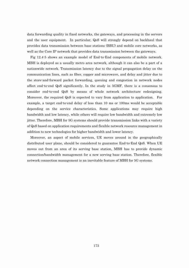
173
data forwarding quality in fixed networks, the gateways, and processing in the servers and the user equipment. In particular, QoS will strongly depend on backhaul that provides data transmission between base stations (BBU) and mobile core networks, as well as the Core IP network that provides data transmission between the gateways.
Fig 12.4-5 shows an example model of End-to-End components of mobile network. MBH is deployed as a usually metro area network, although it can also be a part of a nationwide network. Transmission latency due to the signal propagation delay on the communication lines, such as fiber, copper and microwave, and delay and jitter due to the store-and-forward packet forwarding, queuing and congestion in network nodes affect end-to-end QoS significantly. In the study in 5GMF, there is a consensus to consider end-to-end QoS by means of whole network architecture redesigning. Moreover, the required QoS is expected to vary from application to application. For example, a target end-to-end delay of less than 10 ms or 100ms would be acceptable depending on the service characteristics. Some applications may require high bandwidth and low latency, while others will require low bandwidth and extremely low jitter. Therefore, MBH for 5G systems should provide transmission links with a variety of QoS based on application requirements and flexible network resource management in addition to new technologies for higher bandwidth and lower latency.
Moreover, an aspect of mobile services, UE moves around in the geographically distributed user plane, should be considered to guarantee End-to-End QoS. When UE moves out from an area of its serving base station, MBH has to provide dynamic connection/bandwidth management for a new serving base station. Therefore, flexible network connection management is an inevitable feature of MBH for 5G systems.
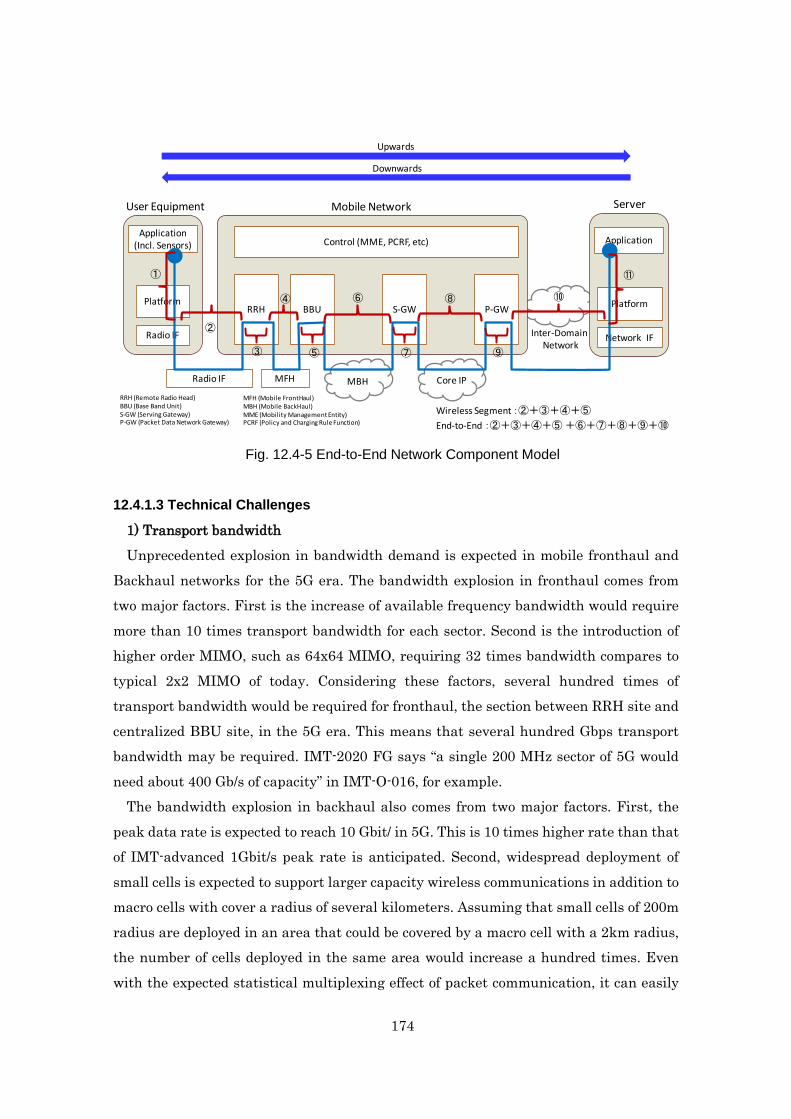
174
Fig. 12.4-5 End-to-End Network Component Model
12.4.1.3 Technical Challenges
1) Transport bandwidth Unprecedented explosion in bandwidth demand is expected in mobile fronthaul and
Backhaul networks for the 5G era. The bandwidth explosion in fronthaul comes from two major factors. First is the increase of available frequency bandwidth would require more than 10 times transport bandwidth for each sector. Second is the introduction of higher order MIMO, such as 64x64 MIMO, requiring 32 times bandwidth compares to typical 2x2 MIMO of today. Considering these factors, several hundred times of transport bandwidth would be required for fronthaul, the section between RRH site and centralized BBU site, in the 5G era. This means that several hundred Gbps transport bandwidth may be required. IMT-2020 FG says “a single 200 MHz sector of 5G would need about 400 Gb/s of capacity” in IMT-O-016, for example.
The bandwidth explosion in backhaul also comes from two major factors. First, the peak data rate is expected to reach 10 Gbit/ in 5G. This is 10 times higher rate than that of IMT-advanced 1Gbit/s peak rate is anticipated. Second, widespread deployment of small cells is expected to support larger capacity wireless communications in addition to macro cells with cover a radius of several kilometers. Assuming that small cells of 200m radius are deployed in an area that could be covered by a macro cell with a 2km radius, the number of cells deployed in the same area would increase a hundred times. Even with the expected statistical multiplexing effect of packet communication, it can easily
RRH
User Equipment
BBU S-GW P-GW
Control (MME, PCRF, etc)
MFH MBH Core IP
Mobile Network Server
Radio IF
Platform
Application(Incl. Sensors)
Network IF
Platform
Application
Upwards
Downwards
MFH (Mobile FrontHaul)MBH (Mobile BackHaul)MME (Mobility Management Entity)PCRF (Policy and Charging Rule Function)
RRH (Remote Radio Head)BBU (Base Band Unit)S-GW (Serving Gateway)P-GW (Packet Data Network Gateway)
Inter-DomainNetwork
Radio IF
①
②
③
④
⑤
⑥
⑦
⑧
⑨
⑩
⑪
Wireless Segment :②+③+④+⑤
End-to-End :②+③+④+⑤+⑥+⑦+⑧+⑨+⑩

175
be assumed that ultra large capacity circuits will be required to support Backhaul between the base stations and the core networks. For example, a minimum 10Gbps access link will be needed for a cell site which has multiple sectors with peak rate of 10Gbps. A N x 100Gbps uplink to a Metro network will be required at an aggregation site which accommodate several hundred cell sites even if 1/10 statistical multiplexing is assumed. Moreover, the required link rate at a Metro Core network that accommodates dozens of Metro Networks would reach to N x Tbps. Table 12.4-1 shows a comparison of the required bandwidth for existing 4G Backhaul networks and 5G Backhaul networks.
Table 12.4-1 Typical Line Rate [bps]
Generation
Backhaul Mobile Core
Access Metro Metro Core Core IP
4G 100M to 1Gbps 10G 10G to 100Gbps
100G
5G 10G N x 100G N x T N x 10T?
2) Functional split The number of mobile networks employing centralized radio access network (C-RAN)
architecture, which consists of base stations (BSs) and remote antenna sites (RASs), is now increasing because of its flexibility to deploy RASs and easiness to realize coordinated multi point (CoMP) transmission/reception. The current C-RAN uses a common purpose radio interface (CPRI) as the de facto standard interface. This CPRI requires a large overhead for sampling analog wireless signals. In detail, the optical bandwidth required by CPRI is more than 10 times as large as the wireless transport rate. If CPRI is still applied to 5G, the required optical bandwidth will be tens of Gbps or more, and it must be a serious problem from the view point of the transceiver cost and its power consumption. Therefore, new interface should be studied to provide effective C-RAN transport.
Bandwidth compression technique is one solution to reduce the optical bandwidth. It is reported that the bandwidth can be reduced to almost half of CPRI, while it degrades the wireless signal.
Another approach is to re-allocate the functions between the BSs and the RASs, which means that some functionality of the BSs is moved to the RASs. This would enable to transport digital data between BSs and RASs so that the large overhead

176
required in CPRI can be suppressed. On the other hand, it also would prevent large part of CoMP gain. So, the challenge is to reduce the optical bandwidth while obtaining the CoMP gain at the same time.
3) Efficiency of fronthaul There is a case which any UEs do not exist in a small cell, since the area of cells is
reduced. Therefore, the system with all base stations are working all the time wastes power consumption. Thus, the movement prediction of UEs and the sleep control of base stations are required.
Fig. 12.4-6 Sleep control by the movement prediction of UEs 4) Reliability and resilience Mobile networks have become a primary source of information and assistance and
many services necessary for daily life now depend on it. 5G is inherently expected to be a part of the social infrastructure, supporting not only voice and Internet services but also providing every day and emergency services essential for people’s daily lives, such as sensor networks and autonomous driving. Therefore, the network has to be more robust than ever against any events, such as network node failure and link failure due to equipment errors, human errors and natural disasters. A variety of protection and restoration methods are available to make fronthaul/backhaul networks robust. In a traditional fronthaul/backhaul system, the network systems have redundant components and network topology is designed to have multiple redundant routes. Protection and restoration protocols across multiple network layers, such as synergy of optical network and packet network, provide automatic recovery from communication failures. In addition to these existing features for reliability, other aspects need to be considered for 5G: • Reliability of fronthaul

177
Fronthaul links require a stable low latency and small jitter transport links. The traditional protection protocol doesn’t work well to recover links without influences of mobile protocols working on it and to user communications. Therefore, new protection features customized for fronthaul is required.
• Efficient Multi-Layer Protection and Restoration Network slicing, meaning introducing separated logical network systems for specific
requirements from applications, is one of the key architectural concepts for 5G. From the view point of fronthaul/backhaul networking, this means providing optimized transport lines for each logical network system by utilizing the capabilities of each network layer. For example, an optical layer can provide an ultra-broadband and low latency “hard pipe”, and packet layer can provide a flexible packet multiplexing “soft pipe”. Fronthaul/Backhaul is constructed by a combination of multiple layer network technologies. Therefore, studies on multi-layer orchestration to provide the best protection and restoration with comprehensive viewpoint are expected.
• Disaster Resilience Fronthaul/backhaul for 5G will be expected to provide a more reliable transport
between base stations and mobile core networks than ever before. Although network operators have made substantial capital investment in physical facilities, such as hardening of buildings and underground cabling, more research is required to improve resilience against large scale disasters such as earthquakes and floods. Multiple backup routes and restoration with consideration of geographical distribution is one of ideas.
5) Diversified types of terminal/traffic/operator/FH&BH It is expected that in 5G many different types of base stations/devices are likely to be
deployed with different transportation requirements and targets. Current transport between wireless base stations are mostly optical fiber and
microwave transmission, and the transport may be inefficient and costly to provide the transport in the future dense deployment using small cell. Wireless transport would be introduced for its inherent flexibility, low cost, and ease of deployment.
The capability of flexible topology and the capability of flexible resource assignment or sharing are necessary for new MFH/MBH to effectively utilize radio resources. Such flexibility also needs to improve other issues, such as reliability, co-existence with other solutions, fast deployment, support of multiple applications with different QoS, network level energy efficiency, etc. For the reliability of shared MFH/MBH, reserved resources

178
have to prevent resource wastefulness or creating obstacles that affect other resources. 6) Support of network slicing / management with FH&BH One of the major architectural themes in 5G is network slicing. The goal of this
concept is to provide dynamic resource allocation and configuration management of the underlying network to the upper layer applications. The underlying network consists of RAT, MFH, MBH, and Transport as Fig. 12.4-7 shows.
Fig. 12.4-7 The sliced network and its relationship to MFH and MBH
a) MFH/MBH equipment MFH/MBH equipment supporting network slicing, as Fig.12.4-7 shows, has a control
plane, data plane and application in every logical slice. Network slices can be a physical or virtual network, and will be necessary for slices to support a characteristic
Mobile packet coreRadio access network (RAN)UE
Control
Slice ASlice B
Slice C
Network management
andorchestration
Applications & Services with various requirements (M2M/ IoT, Content delivery, Tactile)
Cloud
Virtualized networks/platform App-Driven APIAPI
Physical infrastructure ( network , computing and storage resources )
Network resources
Computation and storage resources UE Data Centers
MFH MBH TransportRAT(s)
Slice C
Application
Control plane
AccessIntegration
management
Function #1
Slice ASlice B
Function #2
Function #3 Function #4
a) MFH/MBH equipment
b) Control -plane for slice network
Slice network basedMFH/MBH c) Implementation of application

179
(bandwidth, latency, priority, topology, etc.) of the application. In addition, the transport system in the core networks and MBH/MFH should keep interconnectivity with the existing IP network technology where possible.
b) Control-planes for slice networks in MFH and MBH
For flexible control of mobile network, a control-plane for the slice network is required in MFH and MBH. The assignment of control functions can be configurable for the requirements of each slice network.
c) Implementation of application in MFH and MBH Implementation of application at the aggregation part of MFH and MBH realizes
flexible control according to use-cases and requirements of applications by the appropriate use of the API, where possible. However, it must be noted that typical MFH networks transport very low-level unresolved wireless signals, and so the control would be at an aggregate level.
12.4.2 Fronthaul technologies
12.4.2.1 Economization using PON technology
Since it is expected that a large number of cells will be deployed, economical structure and operation of fronthaul are key issues. Using a PON topology network to solve these issues is one solution, for two reasons:
1) Reuse of existing access networks, and 2) Economic aspects of PON itself. At present, broadband access with capabilities over 1 Gb/s are widely deployed in
several countries. The major relevant systems are G-PON, GEPON, XG-PON, and 10GEPON. These operate using a TDM/TDMA scheme that shares a single optical wavelength channel, and the systems provide generic packet transport. An actual TDMA PON transmission system would be beneficial by applying radio-over-packet style of interworking technology. Technology based on the interworking between radio base station and fronthaul is needed to realize low latency using TDM/TDMA scheme. For a large capacity transmission system, using WDM technology is one reasonable solution to provide more transmission bandwidth, without network restructuring. As basic PON technologies which support these systems/new technologies, bandwidth allocation/multiple access control technologies are used.

180
12.4.2.2 Dynamic control of NW resources and path optimization
To realize the high efficient utilization of network resources (bandwidth and power), the virtualization of MFH with WDM technologies is considered. Fig. 12.4-8 shows the configuration of the virtualized MFH. In this system, when additional bandwidth is required, network capacity increases with adding wavelengths, or if too much excessive bandwidth is used, network devices will go to sleep with decreasing wavelengths to reduce power consumption. Furthermore, a virtualized MFH can achieve diverse QoS requirements using wavelength groups (e.g. low latency service).
Fig. 12.4-8 Configuration of virtualized MFH/MBH using WDM technologies
12.4.2.3 Function Splitting
Re-allocation of the functions between the base station and the remote antenna site can reduce the capacity required in MFH. Several function split points are under consideration as shown in Fig. 12.4-9. When the function split point is defined in a higher layer (at a more left point in the figure), the required capacity becomes smaller, but it becomes difficult to realize Coordinated Multi-Point (CoMP) transmission/reception.
The following options are possible split points: (a) CPRI (conventional) (b) Split PHY

181
(c) MAC-PHY (d) Split MAC (e) RLC-MAC (f) PDCP-RLC (g) Service
Fig. 12.4-9 Options of function split and required capacity
To realize the future MFH with a new function split discussed above, we need a new signal format, i.e. a frame. That can not only reduce the capacity in MFH compared with CPRI but also allows various wire-line networks to be used as the base for the MFH. For example, Ethernet frame is one of the candidates.
12.4.3 Backhaul technologies
12.4.3.1 QoS classify/slicing using virtualization
QoS classify QoS is essential for network slicing because QoS defines network requirements:
guaranteed bit rate, latency, and so on. Especially in terms of E2E latency, MBH has more influence than other network segments, since MBH has long-distance and multi-hop network. Therefore, QoS management on MBH is one of key themes for 5G.
QoS doesn’t define granularity of network slice because the same QoS can be applied to multiple network slices. Granularity of network slice can be defined in the similar way of MEC. The following is the MEC's recommendations for identification of mobile
Small capacity Large capacity
CPRIMAC-PHY Split PHYSplit MACRLC-MACPDCP-RLCService
PHY
RFlowerSP
upperSP
MAC
lowerupperRLCPDCP
BS side Remote antenna side
CoMP capabilityDPS, CS/CB(, JT) JT/JR
CoMP: Coordinated Multi-PointDPS: Dynamic Point SelectionCS: Coordinated SchedulingCB: Coordinated Beam formingJT: Joint TransmissionJR: Joint Reception
RF: Radio FrequencySP: Signal ProcessingRLC: Radio Link ControlPDCP: Packet Data Convergence ProtocolCPRI: Common Public Radio Interface

182
application; - E-RAB policy: Subscriber Profile ID (SPID), Quality Class Indicator (QCI), Allocation Retention Priority (ARP) - Packet: 3-tuple (UE IP address, network IP address, IP protocol) Among these parameters, QCI is the most important for QoS on MBH, because QCI defines latency and error rates as in Table. 12.4-2. Therefore, network slices on MBH should meet QoS defined by QCI. However, QCI isn't attached to mobile user-plane packets, therefore network equipment need to be able to recognize QCI indirectly from them, for example by associating QCI with TEID (Tunnel Endpoint ID) in GTP header or 3 tuple as shown above.
Table 12.4-2 QCI definition in 3GPP TS 23.203
Slicing using virtualization It is certain that both eNB and EPC will be fully virtualized in future mobile
networks. Since the main role of MBH is providing IP reachability between eNB and EPC, network slicing on MBH should adjust itself to influence from virtualization of eNB and EPC. This requires future MBH to provide multipoint VPNs for multi cloud

183
environments as in Fig. 12.4-10. The influence of both virtualizations of eNB and EPC should be examined before considering future MBH.
Fig. 12.4-10 MBH connections between Edge clouds and EPC clouds
With the help of NFV, virtualization of EPC has been evolving in regards to resiliency
and load balancing of EPC. Future MBH should allow virtualized EPC to migrate within and among clouds. One possible method to migrate virtualized EPC among clouds is edge overlay technology, for example VXLAN standardized by IETF NVO3. Edge overlay technology has potential to create flexible network slice by decoupling IP address of EPC from underlay network management. Therefore, VXLAN is a current leading technology to realize network slicing within an EPC cloud.
In addition, eNB is also expected to be virtualized in future because of not only NFV and also CRAN evolution. This means that edge clouds will emerge between MBH and MFH. Moreover, MEC will be supposed to be deployed in these edge clouds to provide additional network services, especially for ultra-low-latency application. Through evolution of these technologies, virtualized BBU will be deployed for each network slice. However, virtualized BBU doesn't need to migrate among edge clouds. This allows use of VLAN for network slice within edge cloud, in addition to VXLAN.
MBH will need to combine seamlessly both network slices of an EPC cloud and an edge cloud. The methods of network slicing on MBH are categorized to the following two

184
types; - Edge overlay: VXLAN, EVPN, MPLS-TP, PBB - Hop by hop: OpenFlow, POF
One advantage of the edge overlay model is the decoupling of the virtualized overlay network from physical underlay network, because edge overlay is an encapsulation technology. This allows operators to enhance total network systems by just updating edge network equipment without updating core network equipment. And also, VXLAN and EVPN can use an existing IP/MPLS network as its underlying network. Protection for network failure can be delegated to this underlying network function. On the other hand, an advantage of hop-by-hop technology is full control of MBH, because the central controller can manage all SDN network equipment. That allows an operator to manage their network as they like, especially regarding latency.
Latency of network slice within MBH In both of edge overlay and hop-by-hop technology, network latency stems from the
physical network. Therefore, monitoring the latency of MBH will be more important in 5Gboth before and after the creation of network slices, no matter if MBH uses edge overlay or hop-by-hop virtualization.
This requires MBH orchestrator to gather network performance information from the physical network and compare it to required QoS as Fig. 12.4-11 shows. After slice control receives network requirements from upper API for application and services, it needs to propagate QoS requirements to not only to the core network orchestration but also MBH orchestration. At this point, MBH orchestration should refer to monitored performance of physical network, and then create network slice with appropriate QoS. After creation of network slice, MBH orchestration should monitor network performance regularly to assure SLA for each network slice.

185
Fig. 12.4-11 Handling QoS with MBH orchestrations
12.4.3.2 Dynamic control of NW resources and path optimization
Backhaul/fronthaul provides transport links between base stations and mobile core networks. In 5G, mobile core functions and application computing capability would be built in a cloud computing environment, and distributed from the network core to the network edge to handle massive traffic or realize the ultra-low latency required by applications.
Fronthaul/backhaul should have dynamic control feature of network resources, such as optical wavelength, transmission bandwidth and priority control. A dynamic path route control with consideration of global resource status is required to achieve resource usage optimization. Fig. 12.4-12 shows an example of resource controls to provide appropriate transport path for each network slice. In Network Slice #1, the direct optical path allows ultra-broadband and low latency communication between the BBU and the Edge/Metro cloud where mobile core features and application servers are enabled. In Network Slice #2, the hop-by-hop packet network allows economical communications with statistical multiplexing between the BBU and the Core cloud where the traditional mobile core and application servers are located.
The resources for these slices should be quickly reserved to guarantee service quality
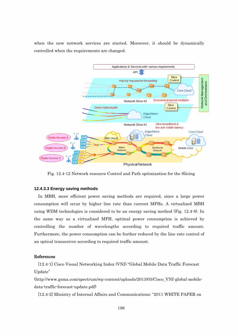
186
when the new network services are started. Moreover, it should be dynamically controlled when the requirements are changed.
Fig. 12.4-12 Network resource Control and Path optimization for the Slicing
12.4.3.3 Energy saving methods
In MBH, more efficient power saving methods are required, since a large power consumption will occur by higher line rate than current MFHs. A virtualized MBH using WDM technologies is considered to be an energy saving method (Fig. 12.4-8). In the same way as a virtualized MFH, optimal power consumption is achieved by controlling the number of wavelengths according to required traffic amount. Furthermore, the power consumption can be further reduced by the line rate control of an optical transceiver according to required traffic amount. References
[12.4-1] Cisco Visual Networking Index (VNI) “Global Mobile Data Traffic Forecast Update” (http://www.gsma.com/spectrum/wp-content/uploads/2013/03/Cisco_VNI-global-mobile-data-traffic-forecast-update.pdf)
[12.4-2] Ministry of Internal Affairs and Communications: “2011 WHITE PAPER on
Mobile Core
BBU cloud
Edge/Metro Cloud
BBU
BBU
BBU
RRU
RRU
RRU
RRU
RRU
RRU
RRU
MetroNetwork
BackboneNetwork
Physical NetworkBBURRU
Radio Access A
Core Cloud
Edge/Metro Cloud
Core Cloud
Radio Access B
Radio Access C
Network Slice #1
Network Slice #2
Ultra-broadband &low and stable latency
Economical packet multiplex
Direct Optical path
Hop-by-hop packet forwarding
Applications & Services with various requirements
Slice Control
Slice Control N
etw
ork
Man
agem
ent
and
Orc
hest
ratio
n
API

187
Information and Communications in Japan” http://www.soumu.go.jp/johotsusintokei/whitepaper/eng/WP2011/2011-index.html (http://www.soumu.go.jp/johotsusintokei/whitepaper/h23.html)"
[12.4-3] Mobile Society Research Institute, NTT DOCOMO, INC. “Disaster resistant information society”, NTT Publishing Co., Ltd., 2013. 12.5 Mobile Edge Computing (MEC)
12.5.1 Overview of MEC
12.5.1.1 General description
As we are approaching year 2020, new network service applications are emerging endlessly. While they may bring amazing experiences to the end user, they also require a more efficient, personalized, intelligent, reliable and flexible network.
Many OTT application providers have identified the demand of managing data at the mobile edge, which has significant advantages. OTT application providers will be able to access to the real time network context information so that they can adjust traffic transmission in a timely fashion. It will also benefit some OTT applications running in the cloud with locally processing huge amounts of data at the mobile edge. This data will only be used for a few seconds and doesn’t have to be sent to the cloud. Mobile users will be able to enjoy the personalized service with ultra-low latency and higher bandwidth.
Recently operator’s key role is to maintain efficient bearing networks, including core networks, radio networks, fronthaul/backhaul networks and backbone networks. The investment and maintenance of them, especially radio access nodes (e.g. base stations and eNBs) and mobile backhaul, is quite costly. Handling data traffic at the mobile edge while providing network context to OTT applications will not only help operators explore new business opportunities but also can reduce radio and mobile backhaul resource consumption.
With the demands of all stakeholders, the concept of mobile edge computing is being seriously considered in the industry. Mobile edge computing is an open IT service environment at a location considered to be the most lucrative point in the mobile network, the radio access network (RAN) edge, characterized by proximity, ultra-low latency and high bandwidth. This environment will offer cloud computing capabilities as well as exposure to real-time radio network and context information. Users of interactive and delay-sensitive applications will benefit from the increased

188
responsiveness of the edge as well as from maximized speed and interactivity. IT economies of scale can be leveraged in a way that will allow proximity, context,
agility and speed to be used for wider innovation that can be translated into unique value and revenue generation. All players in this new value-chain will benefit from closer cooperation, while assuming complementary and profitable roles within their respective business models.
12.5.1.2 Features
Mobile Edge Computing technology enables a lot of new features in the mobile network. - Consumer-oriented services: these are innovative services that generally benefit directly the end-user, i.e. the user using the UE, which includes gaming, remote desktop applications, augmented and assisted reality, cognitive assistance, etc. - Operator and third party services: these are innovative services that take advantage of computing and storage facilities close to the edge of the operator's network. They are usually not directly benefiting the end-user, but can be operated in conjunction with third-party service companies, for example: active device location tracking, big data, security, safety, enterprise services, and etc. - Network performance and QoE improvements: these services are generally aimed at improving performance of the network, either via application-specific or generic improvements. The user experience is generally improved, but these are not new services provided to the end-user. These include content/DNS caching, performance optimization, video optimization, etc. Augmented reality
Augmented reality allows users to have additional information from their environment by performing an analysis of their surroundings, deriving the semantics of the scene, augment it with additional knowledge provided by databases, and feed it back to the user within a very short time. Therefore, it requires low latency and computing/storage either at the mobile edge or on the device.
In augmented reality services, UE can choose to offload part of the device computational load to a mobile edge application running on a mobile edge platform. UE needs to be connected to an instance of a specific application running on the mobile edge computing platform which can fulfil latency requirements of the application, and the interaction between the user and the application needs to be personalized, and
189
continuity of the service needs to be maintained as the user moves around. Data analytics
Some data analytic services need gathering of huge amounts of data (e.g. video, sensor information, etc.) from devices analyzed through a certain amount of processing to extract meaningful information before being sent towards central servers.
In order to support the constraints of the operator or the third party requesting the service, the applications might have to be run on all requested locations, such as mobile edge servers which are very close to the radio nodes. The application running on mobile edge server processes the information and extracts the valuable metadata, which it sends to a central server. A subset of the data might be stored locally for a certain period for later cross-check verification. Mobile video delivery optimization using throughput guidance for TCP
Media delivery is nowadays usually done via HTTP streaming which in turn is based on the Transmission Control Protocol (TCP). The behavior of TCP, which assumes that network congestion, is the primary cause for packet loss and high delay, can lead to the inefficient use of a cellular network's resources and degrade application performance and user experience. The root cause for this inefficiency lies in the fact that TCP has difficulty adapting to rapidly varying network conditions. In cellular networks, the bandwidth available for a TCP flow can vary by an order of magnitude within a few seconds due to changes in the underlying radio channel conditions, caused by the movement of devices, as well as changes in system load when other devices enter and leave the network.
In this feature, a radio analytics Mobile edge application, which uses services of Mobile Edge Computing, provides a suitably equipped backend video server with a near real-time indication on the throughput estimated to be available at the radio downlink interface in the next time instant. The video server can use this information to assist TCP congestion control decisions. With this additional information, TCP does not need to overload the network when probing for available resources, nor does it need to rely on heuristics to reduce its sending rate after a congestion episode.
12.5.1.3 Key challenges
Mobile Edge Computing uses a virtualisation platform for applications running at the mobile network edge. The Mobile edge platform provides a framework for providing services to applications it hosts, with a basic set of middleware services already defined,

190
allowing these applications to have a rich interaction with the underlying network environment, especially to be aware of the radio network status so that appropriate handlings will be made to adapt to the underlying network environment. In addition, radio analytic is exposed to applications through standardized API. See Fig. 12.5-1, below for an overview of MEC framework.
Fig. 12.5-1 Overview of MEC framework To achieve that, there are some key challenges to be considered:
Virtualization Mobile Edge Computing uses a virtualisation platform for applications running at the
mobile network edge. Network Functions Virtualisation (NFV) provides a virtualisation platform to network functions. The infrastructure that hosts their respective applications or network functions is quite similar.
In order to allow operators to benefit to as much as possible from their investment, it would be beneficial to reuse the infrastructure and infrastructure management of NFV to the largest extent possible, by hosting both VNFs (Virtual Network Functions) and Mobile edge applications on the same or similar infrastructure. Mobility
Mobility is an essential component of mobile networks. Most devices connected to a mobile network are moving around within the mobile network, especially when located at cell edge, but also when changing RATs, etc., or during exceptional events.
Some mobile edge applications, notably in the category "consumer-oriented services", are specifically related to the user activity. These applications need to maintain some application-specific user-related information which is synchronized with the instance of that application running on another mobile edge server. Therefore, service continuity

191
should be maintained while the user is moving to an area served by another mobile edge platform which hosts the application. Simple and controllable APIs
In order to enable the development of a strong ecosystem for Mobile Edge Computing, it is very important to develop APIs that are as simple as possible and are directly answering the needs of applications. To the extent this is possible, Mobile Edge Computing specifications need to reuse existing APIs that fulfil the requirements. Application lifecycle management
The Mobile edge platform shall be available for the hosting of Mobile edge applications. The MEC management functionality shall support the instantiation and termination of an application on a Mobile edge server within the Mobile edge system when required by the operator or in response to a request by an authorized third-party. Platform service management
The Mobile edge platform provides services that can be consumed by authorized applications. Applications should be authenticated and authorized to access the services. The services announce their availability when they are ready to use, and mobile edge applications can discover the available services. Traffic routing
The mobile edge platform routes selected uplink and/or downlink user plane traffic between the network and authorized applications and between authorized applications. One or more applications might be selected for the user plane traffic to route through with a predefined order. The selection and routing during traffic redirection are based on re-direction rules defined by the operator per application flow. The selected authorized applications can modify and shape user plane traffic. Data forwarding to edge or conventional computing server
User data needs to be placed into one of two different categories, depending on the service nature. One category would be data which are processed in application server of data center (DC) or the cloud. The other category is service data which should be processed near the edge. For example, delay critical application data or localized proximity service data should be processed in the edge network, while some other application data are addressed to the conventional servers in DC or cloud. In order to conduct that way systematically, an identifier presenting data types and the control entity will be required in order to address the application data to edge network or to the conventional network.

192
Control signal transfer management Because some types of user application data should be processed in the edge network,
service specific control signals may be needed to be combined with the edge local operation in order for data to be transferred to the edge network efficiently. Hence, a management capability will be required so that the control signals are combined or transferred to the local edge control entity for processing MEC application data. Inter-edge mobility
Mobile edge service areas may consist of contiguous spots or isolated spots. The question arises about how those proximity services can be seamlessly transmitting data even when the devices are moving around local areas across multiple edge networks. One solution is requiring transferring cached service data from a source edge to a destination edge server. In addition, sharing device positioning information among neighbor edge sites will be useful for tracking the mobile device, especially in the case that pin-point serving spots are distributed. That capability may be realized by means of some positioning systems or any type of spot marking assistance technologies.
Gap analysis
Support enhanced MEC management of virtualization Mobile Edge Computing uses a virtualisation platform for applications running at the
mobile network edge. Although Mobile edge server lifecycle management supported by existing NFV-MANO, while MEC management should support some enhancements in following aspects:
1) Mobile edge application lifecycle management: The MEC management functionality should support the instantiation and termination of an application on a Mobile edge server within the Mobile edge system when required by the operator or in response to a request by an authorized third-party.
Mobile edge application service management: The Mobile edge platform provides services that can be consumed by authorized applications. Applications should be authenticated and authorized to access the services. The services announce their availability when they are ready to use, and mobile edge applications can discover the available services.
Support inter-edge mobility Mobility, of course, is an essential component of mobile networks. Considering some
mobile edge applications are specifically related to the user activity, it needs to

193
maintain some application-specific user-related information that needs to be provided to the instance of that application running on another mobile edge server. Therefore, service continuity should be maintained while the user is moving to an area served by another mobile edge platform which hosts the application. So MEC system should to support inter-edge mobility mechanism for service continuity.
Support more simple and controllable APIs In order to enable the development of a strong ecosystem for mobile edge computing,
it is important to develop APIs that are as simple as possible and are directly meeting the needs of applications. In addition, radio analytics/radio network information is provided through a standardized API and if there are enhancements required. MEC system should optimized existing APIs to make it more simple and controllable.
Support traffic routing among multiple applications The mobile edge platform routes selected uplink and/or downlink user plane traffic
between the network and authorized applications and between authorized applications. More than one application might be selected for the user plane traffic to route through properly (e.g. video optimization, augmented reality). The MEC system should support traffic routing mechanism among multiple applications: selection and routing during traffic redirection based on re-direction rules which is defined by the operator per application flow, and selected authorized applications can modify and shape user plane traffic.
12.5.2 Application of MEC
12.5.2.1 Ultra-low latency networking
In the 5G era, non-perceptional latency is expected for realizing zero-distance user experience. That will be necessary in some features of delay critical interactive services or systems, since sub-1ms response time is required to realize quick recognition, reaction, and control.
In fact, we experience interaction with any system as intuitive and natural, only if the feedback of the system is adapted to our human reaction time. The required response time for interactive systems enabling real-time reactions depends on perceptual human senses.
Following description texts are extraction from ITU-T Technology Watch Report “The Tactile Internet” (August 2014).
===========================================================

194
Fig. 12.5-2 Order of magnitude of human reaction times
Source: The Tactile Internet, ITU-T Technology Watch Report, Aug. 2014 An intuitive example is interactive web browsing. To experience immediacy, the page
build-up after clicking on a link should be a fraction of the human unprepared reaction time. Real-time experience for browsing interaction is achieved only if a new web page can be built-up within a few hundred milliseconds of a user clicking on a hyperlink. If a human is prepared for a situation, it is clear that a faster reaction time is needed.
The human auditory reaction time is about 100 milliseconds. To enable natural conversation, modern telephony is designed to ensure that voice is transmitted within 100 milliseconds. Higher latencies would disturb us.
A typical human visual reaction time is in the range of 10 milliseconds. To allow for a seamless video experience, modern TV sets have a minimum picture-refresh rate of 100 Hertz, translating into a maximum inter-picture latency of 10 milliseconds.
But if a human is expecting speed, such as when manually controlling a visual scene and issuing commands that anticipate rapid response, 1-millisecond reaction time is required. Examples are moving a mouse pointer over a screen and viewing a smooth path of the pointer over the screen, or moving our heads while wearing Virtual Reality (VR) goggles and expecting an immediate response from the visual display.
In principle, all of our human senses can interact with machines, and technology’s potential in this respect is growing.
============================================================ It should be noted that these levels of quick response with low latency are required
not only for services that augment human perception, but also some delay-critical applications for M2M/IOT systems as well.
In addition, quick connections and quick responses from the network are also desired for the control signal processing on the control plane as well.
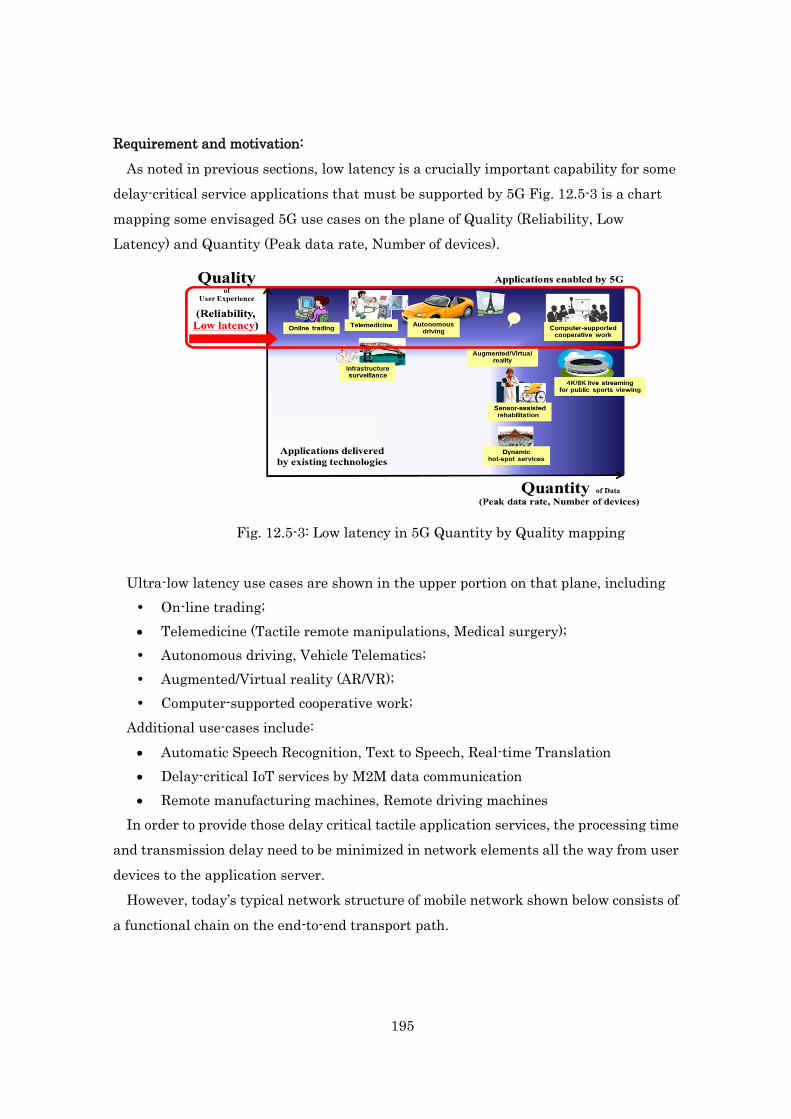
195
Requirement and motivation: As noted in previous sections, low latency is a crucially important capability for some
delay-critical service applications that must be supported by 5G Fig. 12.5-3 is a chart mapping some envisaged 5G use cases on the plane of Quality (Reliability, Low Latency) and Quantity (Peak data rate, Number of devices).
Fig. 12.5-3: Low latency in 5G Quantity by Quality mapping
Ultra-low latency use cases are shown in the upper portion on that plane, including On-line trading; • Telemedicine (Tactile remote manipulations, Medical surgery); Autonomous driving, Vehicle Telematics; Augmented/Virtual reality (AR/VR); Computer-supported cooperative work;
Additional use-cases include: • Automatic Speech Recognition, Text to Speech, Real-time Translation • Delay-critical IoT services by M2M data communication • Remote manufacturing machines, Remote driving machines
In order to provide those delay critical tactile application services, the processing time and transmission delay need to be minimized in network elements all the way from user devices to the application server.
However, today’s typical network structure of mobile network shown below consists of a functional chain on the end-to-end transport path.
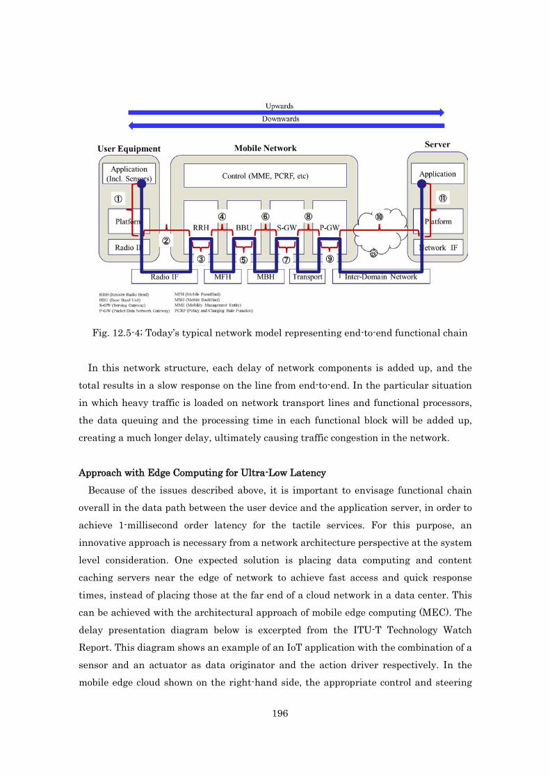
196
Fig. 12.5-4; Today’s typical network model representing end-to-end functional chain
In this network structure, each delay of network components is added up, and the total results in a slow response on the line from end-to-end. In the particular situation in which heavy traffic is loaded on network transport lines and functional processors, the data queuing and the processing time in each functional block will be added up, creating a much longer delay, ultimately causing traffic congestion in the network.
Approach with Edge Computing for Ultra-Low Latency
Because of the issues described above, it is important to envisage functional chain overall in the data path between the user device and the application server, in order to achieve 1-millisecond order latency for the tactile services. For this purpose, an innovative approach is necessary from a network architecture perspective at the system level consideration. One expected solution is placing data computing and content caching servers near the edge of network to achieve fast access and quick response times, instead of placing those at the far end of a cloud network in a data center. This can be achieved with the architectural approach of mobile edge computing (MEC). The delay presentation diagram below is excerpted from the ITU-T Technology Watch Report. This diagram shows an example of an IoT application with the combination of a sensor and an actuator as data originator and the action driver respectively. In the mobile edge cloud shown on the right-hand side, the appropriate control and steering

197
are processed and send back from the associated server, which will be able to achieve a low delay action; e.g. 1m second.
Fig. 12.5-5: Exemplary latency budget of a system of the Tactile Internet Source: The Tactile Internet, ITU-T Technology Watch Report, Aug. 2014
This diagram represents the mobile edge computing model that can be implemented
to introduce the concept of a functional chain executed on the edge side of the network. In this model, application data is processed in a server that combines computation and storage which is then placed in an edge cloud network near to the user rather than a data center in the service cloud that is located far from the user.
Fig. 12.5-6 Edge computing model for ultra-low latency networking In Fig. 12.5-6, user data transactions are processed in a local edge network with the
computing and cache server. Those functions are moved "closer" to the edge depending on the service, considering all requirements in regards to the application, mobility, traffic volume, and/or latency in order to optimize data transmission.

198
In addition, the mobile-edge computing architecture potentially owns some more network capabilities as follows: Location-/Service-awareness proximity services Big-data collection and processing on a real-time basis Disaster relief emergency services provision from local edge servers
Furthermore, it should be noted that the edge computing will be able to work not only
on the user application data but also on some sequential signaling message processing as well. By introducing the control plane processing conduction in the edge network for some application signaling, the terminal devices will have a benefit of low delay control of quick attaching to network by reducing the connection time.
The figure below shows an image of mobile-edge computing network attached to the conventional mobile network. It shows that some application data are going into edge networks, while other ordinary data are going into the conventional core network and data center.
Fig. 12.5-7 Data flow image in the mobile edge network and the conventional
network However, it should be noted that ultra-low latency performance should be facilitated
for a fraction of traffic compared to total traffic of network. Mobile-edge computing will effectively work for the delay critical service data, but it should not be processed for other data which do not need for delay sensitive services. It is necessary that some suitable application data are addressed to the mobile edge computing network to obtain the benefits of ultra-low latency and so on, while other ordinary data are transported to conventional core network or further into the data center to get the appropriate

199
performance of services. This situation creates some trade-offs and so a good balance of edge computing and
conventional network operation is required. In the case that application data computing is processed in the edge side of network, then the response time will become quite small. In addition, the data traffic loaded on the backhaul network and the core network functional nodes will be relaxed with mitigation to some extent. However, on the other hand, the data processing workload together with the required storage capacity become relatively much heavy and larger in the edge network side, and more network facility and higher level of performance of data computing capability will be required in the edge network.
In addition, because the edge-computing local clouds are placed in some distributed locations for some proximity service processing, the user device mobility across those edge networks needs to be considered in order to realize seamless handover of inter-edge networks for some concerned mobile applications.
Fig. 12.5-8 Application of MEC
Challenge for better mobile-edge computing
The Following items need to be considered as a potential challenge to be resolved for a better introduction and operation of mobile edge computing network in order to provide ultra-low latency.
(1) Data forwarding to edge or conventional computing server
User data can be placed into two categories depending on the nature of the service.

200
One category is data which are processed in application server of data center (DC) or the cloud. Another category is the service data which should be processed near the edge. For example, delay critical application data or localized proximity service data should be processed in the edge network, while some other application data are addressed to conventional servers in DC or cloud. In order to direct traffic systematically, an identifier presenting data types and the control entity will be required in order to address the application data to edge network or to the conventional network. (2) Control signal transfer management
Because some types of user application data should be processed in the edge network, the service specific control signals may be needed to be combined with the edge local operation, or need to be transferred to the edge network for processing the control signals efficiently. Hence, a management capability will be required so that the control signals are combined or transferred to the local edge control entity for processing MEC application data. This mechanism of control signal manipulation on the edge network side would also help in making a benefit of short connection time to network with terminal devices. (3) Inter-edge mobility
Mobile edge service areas may consist of contiguous spots or isolated spots. A question arises how those proximity services can be seamlessly provided even when the devices move around the local areas across multiple edge networks. One solution to this issue is to transfer data that has been cached from a source edge server to a destination edge server. If device positioning information can be shared among destination edge severs, this information can also be used to more efficiently distribute data across edge servers. This capability may be realized through use of positioning systems or any other spot marking assistance technology. 12.5.2.2 Control and Management for low latency and resilient networks
Introduction of the massive number of UEs in 5G and their frequent mobility would impose challenges to providing low latency communication in robust infrastructure. MEC can play an important role in addressing this issue because the current technologies of IP mobility management such as Mobile IP or Proxy Mobile IP are not enough. They require a single common anchor point to sit in both the control and data planes for maintaining reachability (i.e. location management) information of UEs, performing handover signaling (i.e. location update), and tunneling data packets. The
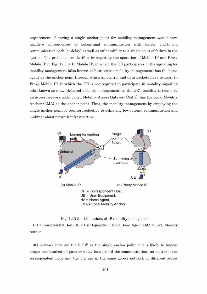
201
requirement of having a single anchor point for mobility management would have negative consequences of suboptimal communication with longer end-to-end communication path (or delay) as well as vulnerability to a single point of failure in the system. The problems are clarified by depicting the operation of Mobile IP and Proxy Mobile IP in Fig. 12.5-9. In Mobile IP, in which the UE participates in the signaling for mobility management (also known as host-centric mobility management) has the home agent as the anchor point through which all control and data packets have to pass. In Proxy Mobile IP, in which the UE is not required to participate in mobility signaling (also known as network-based mobility management) as the UE’s mobility is traced by an access network node, called Mobility Access Gateway (MAG), has the Local Mobility Anchor (LMA) as the anchor point. Thus, the mobility management by employing the single anchor point is counterproductive to achieving low latency communication and making robust network infrastructure.
Fig. 12.5-9 – Limitations of IP mobility management
CH = Correspondent Host, UE = User Equipement, HA = Home Agent, LMA = Local Mobility
Anchor
4G network now use the S-GW as the single anchor point and is likely to impose longer communication path or delay because all the communication, no matter if the correspondent node and the UE are in the same access network or different access

202
networks, has to pass through the S-GW which is located in the core network. Therefore, in order to meet the low latency, high throughput communications to massive number of devices in 5G, we must develop distributed mobility management architecture where there exist multiple anchor points located closer to the UE in the access network. MEC concept can be extended for this purpose as described below.
Fig. 12.5-10 shows a possible structure of 5G systems with distributed mobility anchor (MA) points collocated with the BBU. The BBU are connected to multiple SGWs, which are further connected to multiple PGW. This multihoming configuration makes the network resilient to the node and link failure (e.g., due to overload or natural disasters). Namely, the network remains functioning even when a PGW, SGW, BBU or link between them gets damaged. In this configuration the BBUs get different IP address prefix blocks from different SGWs. Consequently, a UE located in a cell can be assigned with multiple IP addresses anchored with different SGWs. In this case, when the UE moves from one cell to another within the domain of a BBU, it is not required to change any of its addresses and continue communication using them. Even if the UE moves from a domain of one BBU to another BBU it is not required to change its addresses because the addresses assigned to the UE in the previous BBU are still valid in the new BBU as they belong under the same sets of SGWs.
The data being sent from the external data server will be passing through the PGW, SGW, BBU and this path remains the same when the UE moves from one cell to another belonging to the same BBU. When the UE moves to a new cell belonging to a different BBU, the addresses are still valid and the communication from the external data server can continue via the same SGW. However, the path may not be optimal when the distance between the new BBU and the SGW has become longer than the distance of the previous BBU from the SGW. The suboptimal path would be detected by the MA collocated in the new BBU and it would instruct the UE to switch the IP address to the other one which is anchored with the shortest distant SGW. For example, in Fig. 12.5-10, when the UE moves from position A to B, the MA of the new BBU instructs the UE to use IP address with the prefix assigned from the right side SGW for the optimal shortest path communication.
To allow the UE dynamically change the IP addresses used for a communication session without interrupting the application, the application should not use the IP address for the identification of the service or the communication endpoints. The application should use location-independent static IDs and these IDs should be able to
203
be mapped to different IP addresses in the underlying layers of the communication protocols stack. The communication by using IDs is known as the ID-based communication.
In ID-based communication, it is also necessary to store the mapping records between the IDs and addresses (also known as locators). The ID registry (IDR) system, collocated with some other component, would store the ID/address mapping records and provide the record to a correspondent node that wishes to communicate with the UE.
Communication between two UEs located in cells belonging to the same BBU will take place through the BBU, and the communication between UEs located in different BBUs will also take place through the SGW. It means the end-to-end latency of communication between UEs would be at most one round trip time between the UE and the SGW. This latency remains the same even when the UEs move from one cell to another.
Moreover, to reduce the latency of data downloading services, such as popular events video or news, provisioning caching facility collocated with the MA would be helpful. In this case, when the video or news data is downloaded from the external data server for the first time, the data is cached in the BBU so that whenever a new UE requests for the same data service, the request will be served immediately with the data cached in the BBU. For the purpose, the information centric networking approach is useful. The BBU would have both the cache storage facility as well as computing or in-networking processing facility (provided by MEC) so that it would be able to serve user requests not only for the cached data but also for additional intelligence derived from the data. This offloading of computation tasks from the mobile UE would help in reduce service latency because the UE is not required to download the related huge data and perform heavy computation. This would greatly help in improving quality of experience of mobile communication services and applications.
Thus, we can conclude that the adoption of distributed mobility management, ID-based communication, and information centric networking in 5G network architecture from the design phase would be helpful to achieve low latency communication and make the failure resilient system.

204
Fig. 12.5-10 – Distributed mobility anchor points and caching provisioning in 5G systems