Embed Size (px)
Citation preview
8/19/2019 12 NDR and Gunn Devices
http://slidepdf.com/reader/full/12-ndr-and-gunn-devices 1/24
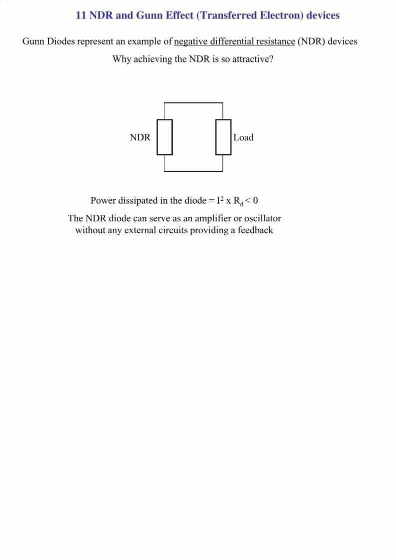
11 NDR and Gunn Effect (Transferred Electron) devices
Gunn Diodes represent an example of negative differential resistance (NDR) devices
Why achieving the NDR is so attractive?
NDR Load
Power dissipated in the diode = I2 x R d
< 0
The NDR diode can serve as an amplifier or oscillator
without any external circuits providing a feedback
8/19/2019 12 NDR and Gunn Devices
http://slidepdf.com/reader/full/12-ndr-and-gunn-devices 2/24
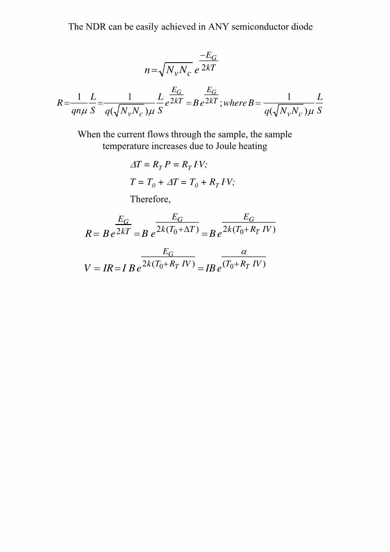
The NDR can be easily achieved in ANY semiconductor diode
kT
E
cv
G
e N N n 2
−
=
S
L
N N q Bwheree Be
S
L
N N qS
L
qn R
cvkT
E
kT
E
cv
GG
µ µ µ )(
1;
)(
1122 ====
When the current flows through the sample, the sample
temperature increases due to Joule heating
∆T = RT P = RT I .V;
T = T 0 + ∆T = T 0 + RT I .V;
Therefore,
)(2)(22 00 IV RT k
E
T T k
E
kT
E
T
GGG
e Be Be B R +∆+
===
)()(2 00 IV RT IV RT k E
T T
G
e IBe B I IRV ++
===α
8/19/2019 12 NDR and Gunn Devices
http://slidepdf.com/reader/full/12-ndr-and-gunn-devices 3/24
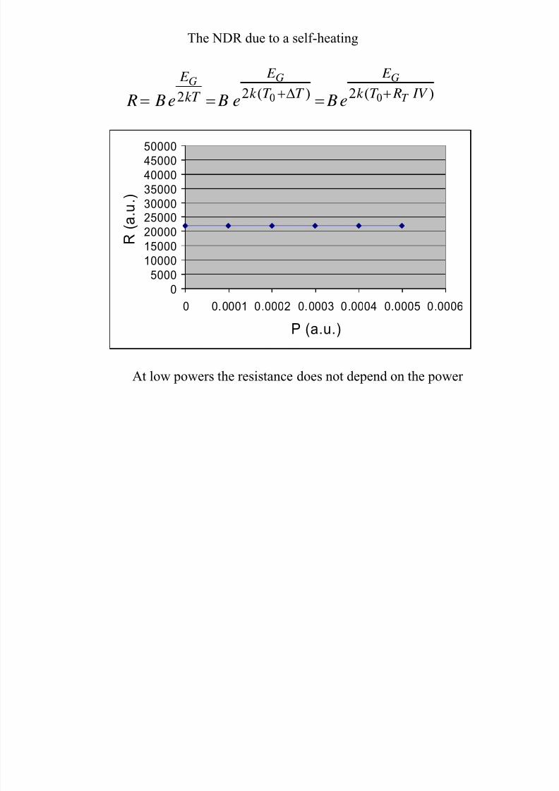
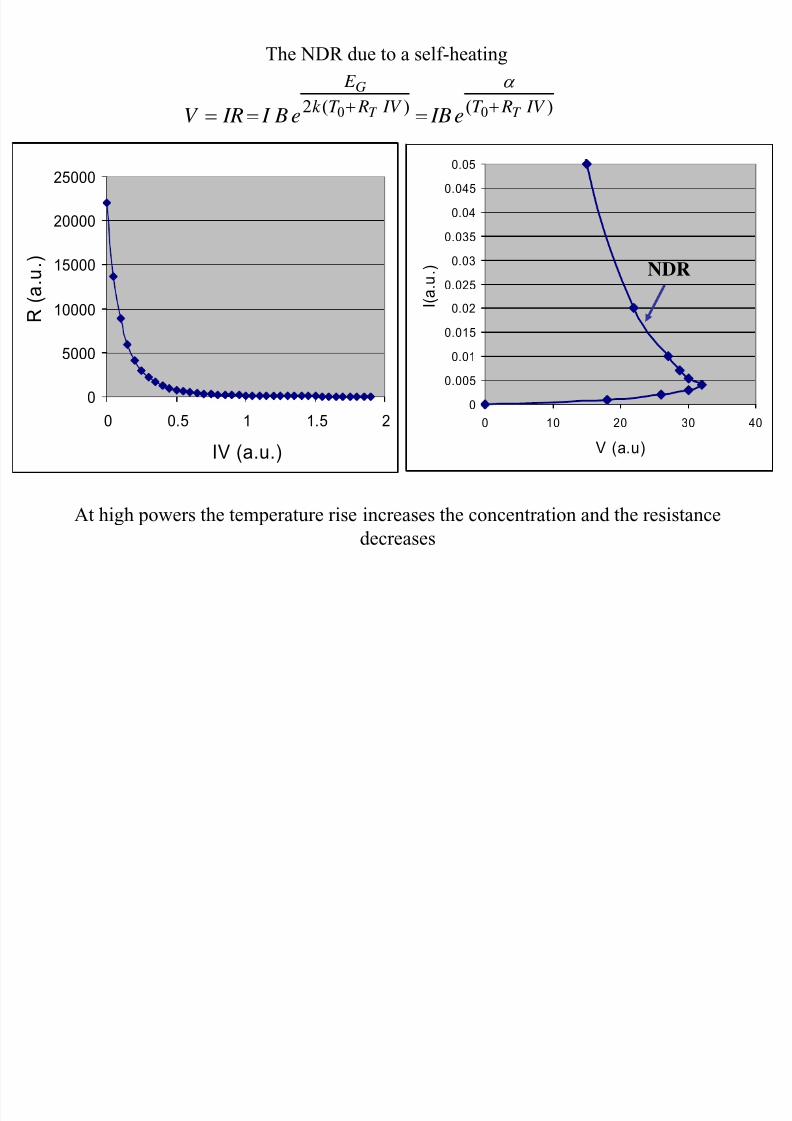
The NDR due to a self-heating
0
5000
10000
15000
2000025000
30000
35000
40000
4500050000
0 0. 0001 0 .0002 0. 0003 0 .0004 0.0005 0 .0006
P (a.u.)
R ( a
. u . )
)(2)(22 00 IV RT k E
T T k E
kT
E
T
GGG
e Be Be B R +∆+
===
At low powers the resistance does not depend on the power
8/19/2019 12 NDR and Gunn Devices
http://slidepdf.com/reader/full/12-ndr-and-gunn-devices 4/24
)()(2 00 IV RT IV RT k
E
T T
G
e IBe B I IRV ++ ===
α
The NDR due to a self-heating
0
5000
10000
15000
20000
25000
0 0.5 1 1.5 2
IV (a.u.)
R ( a . u . )
0
0.005
0.01
0.015
0.02
0.025
0.03
0.035
0.04
0.045
0.05
0 10 20 30 40
V (a.u)
I ( a . u . )
At high powers the temperature rise increases the concentration and the resistancedecreases
NDR
8/19/2019 12 NDR and Gunn Devices
http://slidepdf.com/reader/full/12-ndr-and-gunn-devices 5/24
0 5 10 15 20 250
0.05
0.1
0.15
0.2
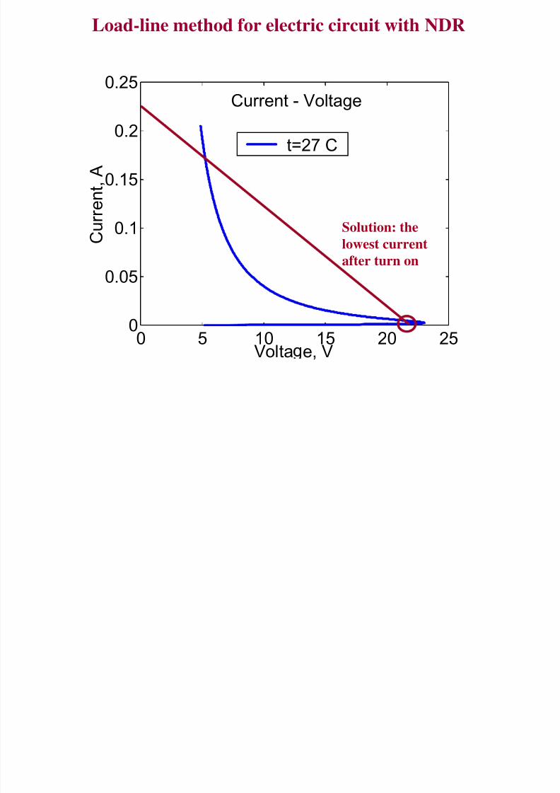
0.25Current - Voltage
Volta e, V
C u r
r e n t , A
t=27 C
Load-line method for electric circuit with NDR
Solution: the
lowest current
after turn on
8/19/2019 12 NDR and Gunn Devices
http://slidepdf.com/reader/full/12-ndr-and-gunn-devices 6/24
0 5 10 15 20 250
0.05
0.1
0.15
0.2
0.25
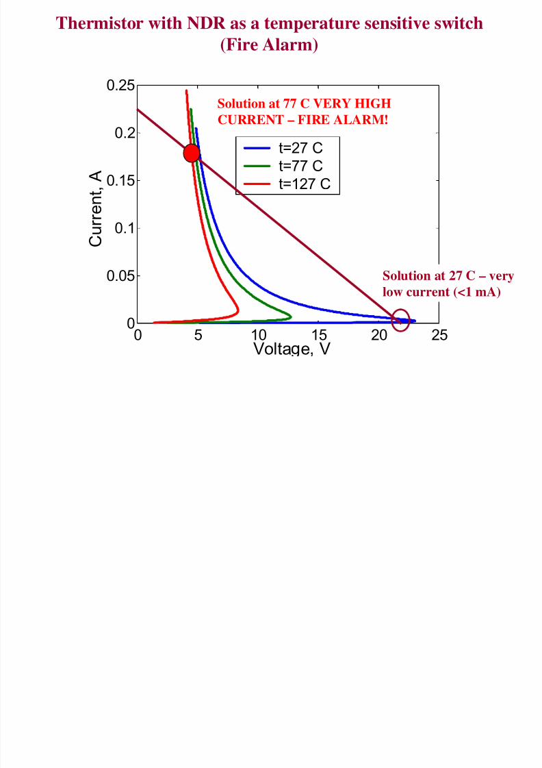
Current - Voltage
Volta e V
C u r r e
n t , A
t=27 Ct=77 C
t=127 C
Thermistor with NDR as a temperature sensitive switch
(Fire Alarm)
Solution at 27 C – very
low current (<1 mA)
Solution at 77 C VERY HIGH
CURRENT – FIRE ALARM!
8/19/2019 12 NDR and Gunn Devices
http://slidepdf.com/reader/full/12-ndr-and-gunn-devices 7/24
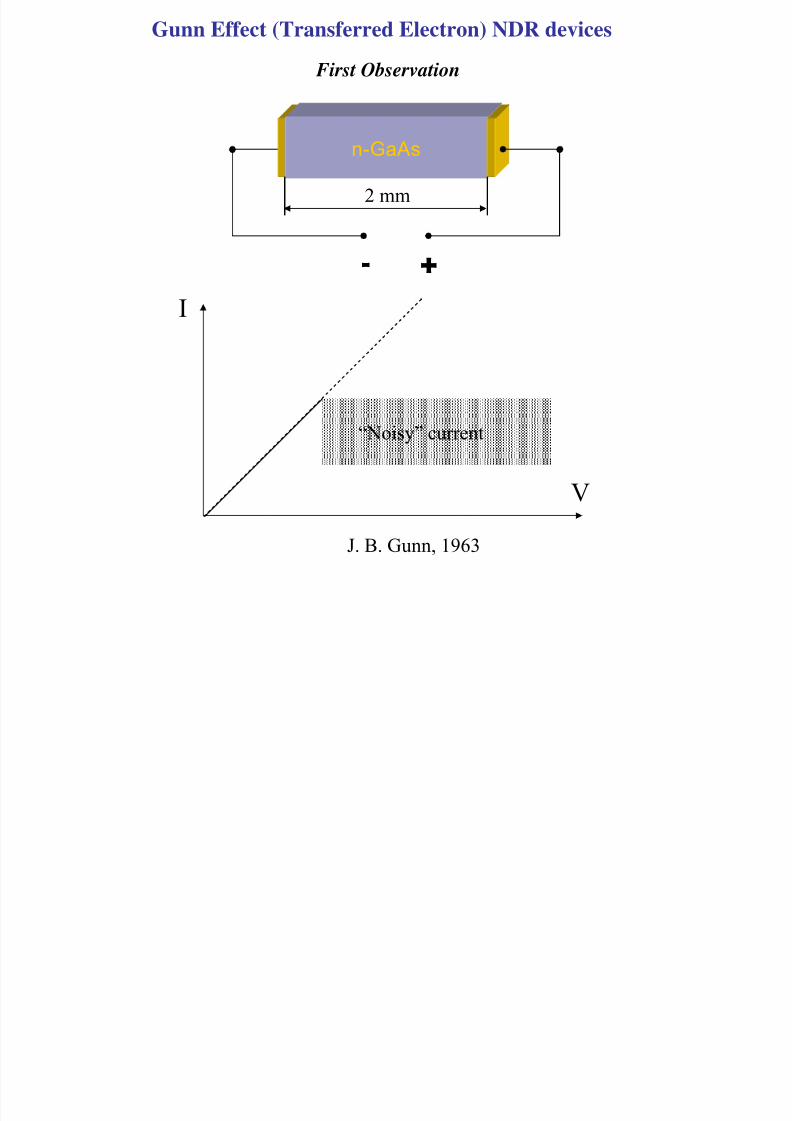
Gunn Effect (Transferred Electron) NDR devices
First Observation
n-GaAs
+-
J. B. Gunn, 1963
I
V
2 mm
“Noisy” current
8/19/2019 12 NDR and Gunn Devices
http://slidepdf.com/reader/full/12-ndr-and-gunn-devices 8/24
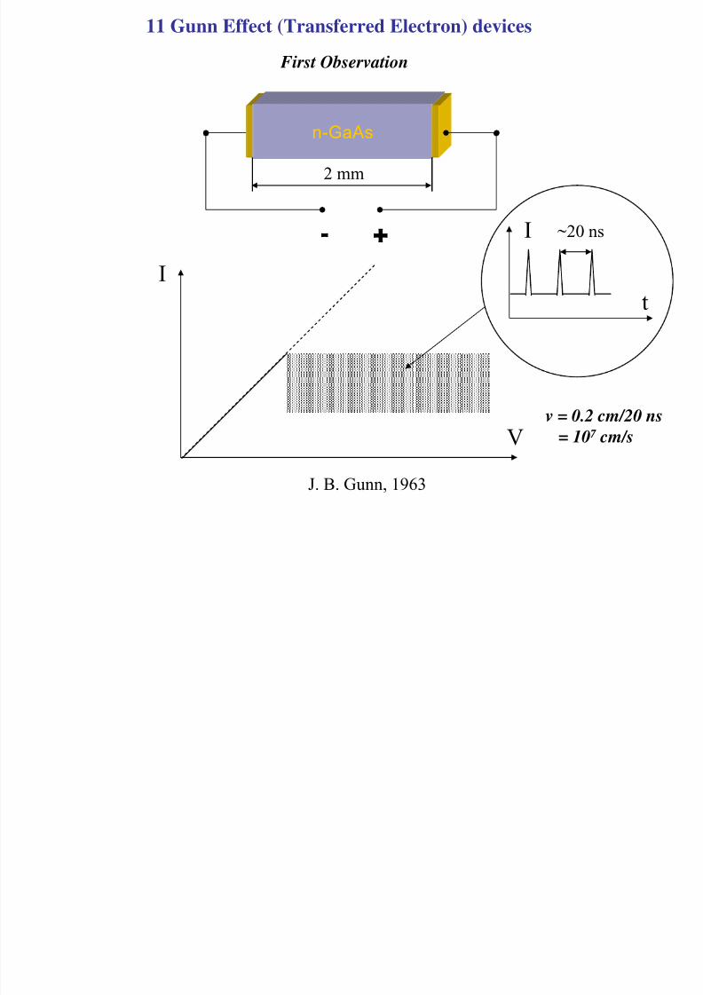
11 Gunn Effect (Transferred Electron) devices
First Observation
n-GaAs
+-
J. B. Gunn, 1963
I
V
t
I ~20 ns
2 mm
v = 0.2 cm/20 ns
= 107 cm/s
8/19/2019 12 NDR and Gunn Devices
http://slidepdf.com/reader/full/12-ndr-and-gunn-devices 9/24
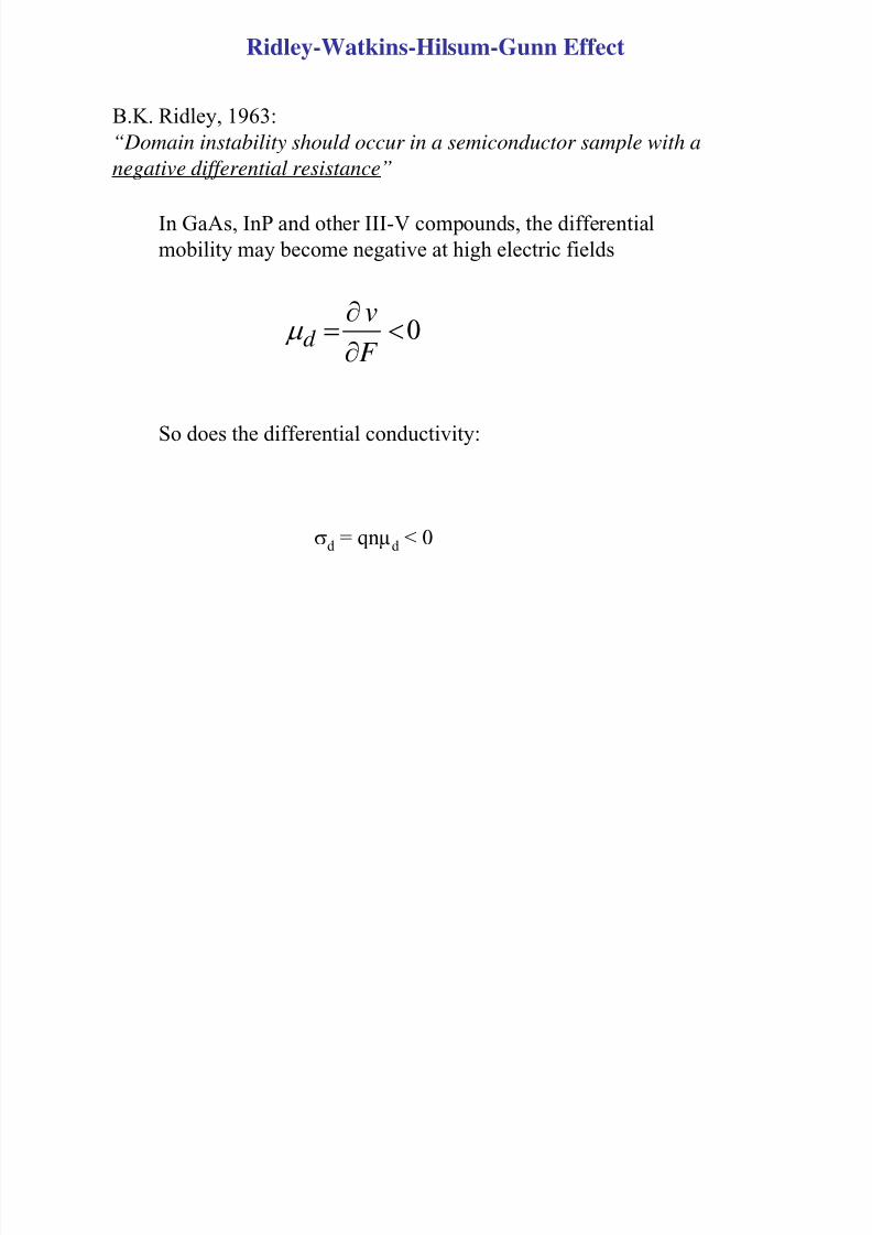
Ridley-Watkins-Hilsum-Gunn Effect
B.K. Ridley, 1963:“Domain instability should occur in a semiconductor sample with a
negative differential resistance”
0<∂
∂
= F
v
d µ
σd = qnµd < 0
In GaAs, InP and other III-V compounds, the differentialmobility may become negative at high electric fields
So does the differential conductivity:
8/19/2019 12 NDR and Gunn Devices
http://slidepdf.com/reader/full/12-ndr-and-gunn-devices 10/24
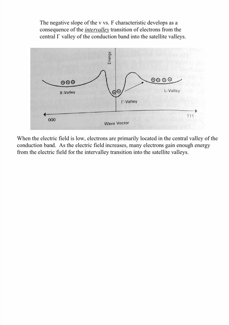
The negative slope of the v vs. F characteristic develops as a
consequence of the intervalley transition of electrons from thecentral Γ valley of the conduction band into the satellite valleys.
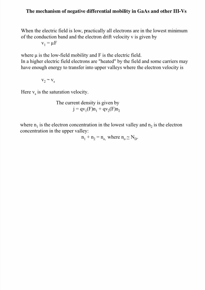
When the electric field is low, electrons are primarily located in the central valley of the
conduction band. As the electric field increases, many electrons gain enough energy
from the electric field for the intervalley transition into the satellite valleys.
8/19/2019 12 NDR and Gunn Devices
http://slidepdf.com/reader/full/12-ndr-and-gunn-devices 11/24
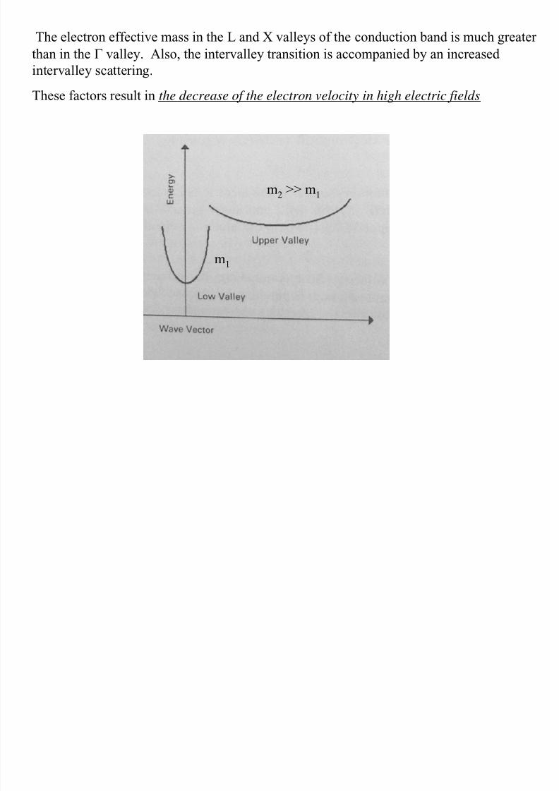
The electron effective mass in the L and X valleys of the conduction band is much greater
than in the Γ valley. Also, the intervalley transition is accompanied by an increased
intervalley scattering.These factors result in the decrease of the electron velocity in high electric fields
m2 >> m1
m1
8/19/2019 12 NDR and Gunn Devices
http://slidepdf.com/reader/full/12-ndr-and-gunn-devices 12/24
8/19/2019 12 NDR and Gunn Devices
http://slidepdf.com/reader/full/12-ndr-and-gunn-devices 13/24
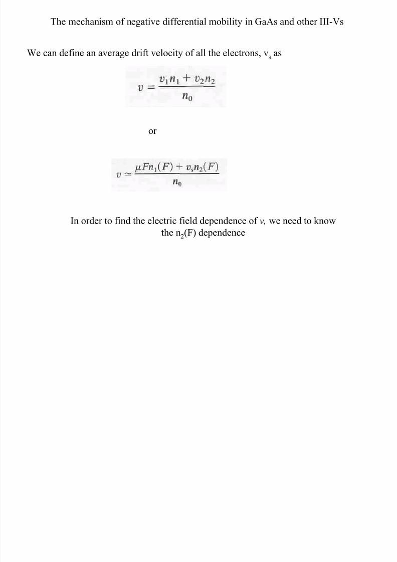
The mechanism of negative differential mobility in GaAs and other III-Vs
We can define an average drift velocity of all the electrons, vs as
or
In order to find the electric field dependence of v, we need to know
the n2(F) dependence
8/19/2019 12 NDR and Gunn Devices
http://slidepdf.com/reader/full/12-ndr-and-gunn-devices 14/24
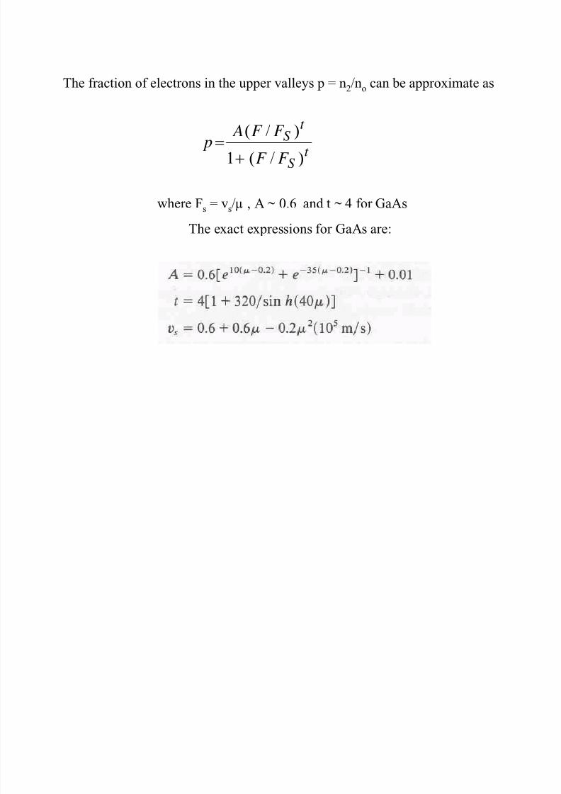
The fraction of electrons in the upper valleys p = n2/no can be approximate as
t S
t S
F F
F F A
p )/(1
)/(
+=
where Fs = vs/µ , A ~ 0.6 and t ~ 4 for GaAs
The exact expressions for GaAs are:
8/19/2019 12 NDR and Gunn Devices
http://slidepdf.com/reader/full/12-ndr-and-gunn-devices 15/24
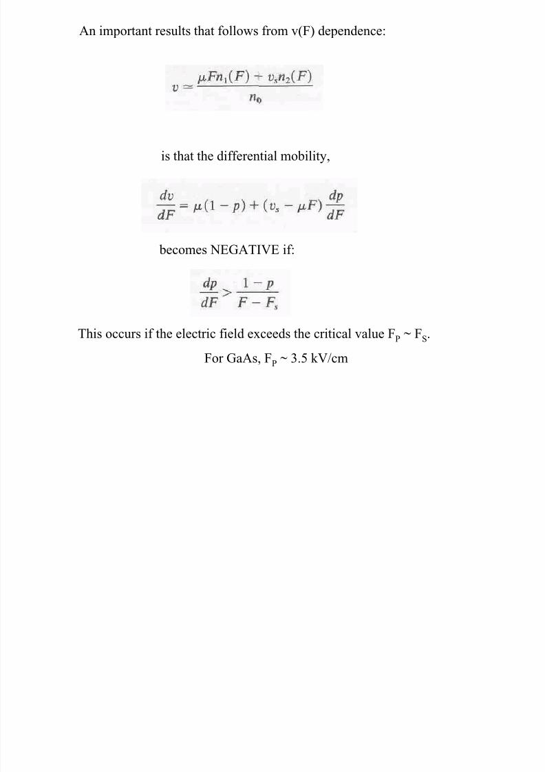
An important results that follows from v(F) dependence:
is that the differential mobility,
becomes NEGATIVE if:
This occurs if the electric field exceeds the critical value FP ~ FS.
For GaAs, FP ~ 3.5 kV/cm
8/19/2019 12 NDR and Gunn Devices
http://slidepdf.com/reader/full/12-ndr-and-gunn-devices 16/24
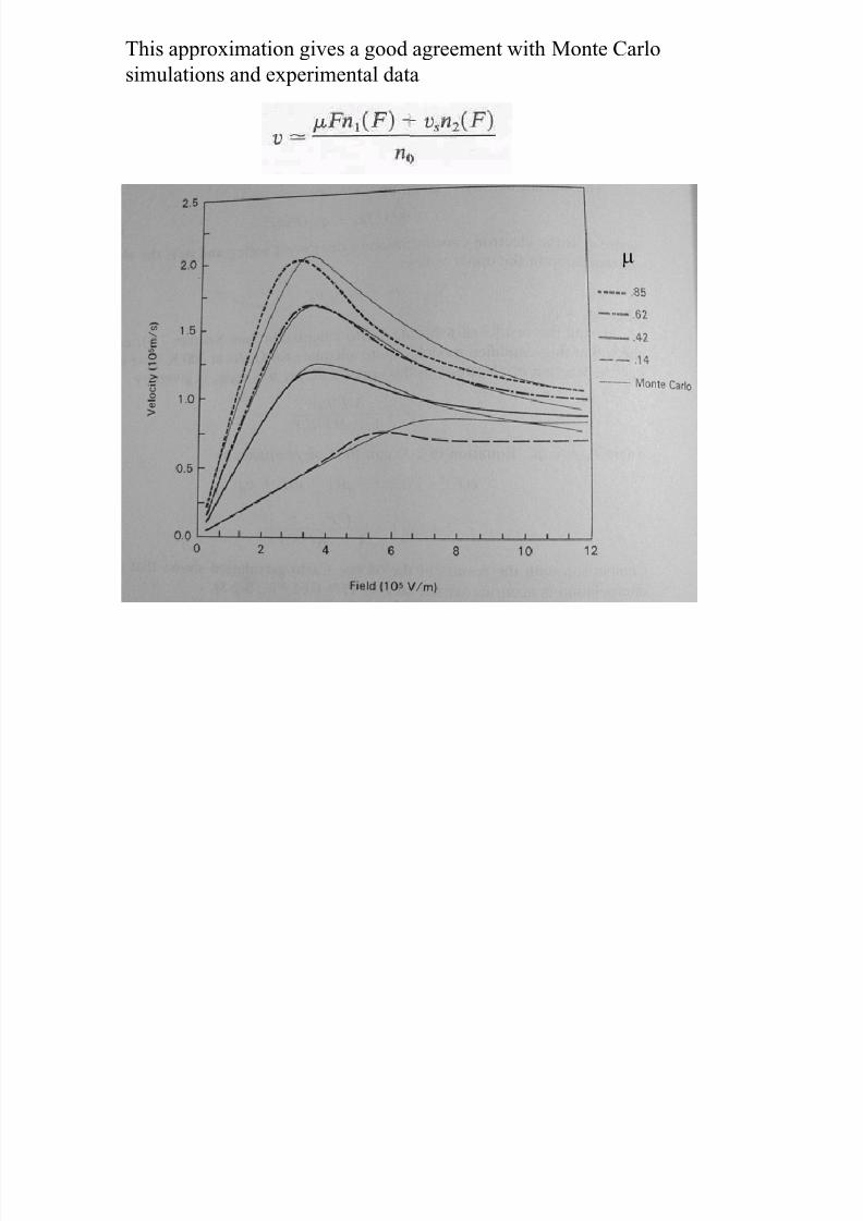
This approximation gives a good agreement with Monte Carlo
simulations and experimental data
µ
8/19/2019 12 NDR and Gunn Devices
http://slidepdf.com/reader/full/12-ndr-and-gunn-devices 17/24
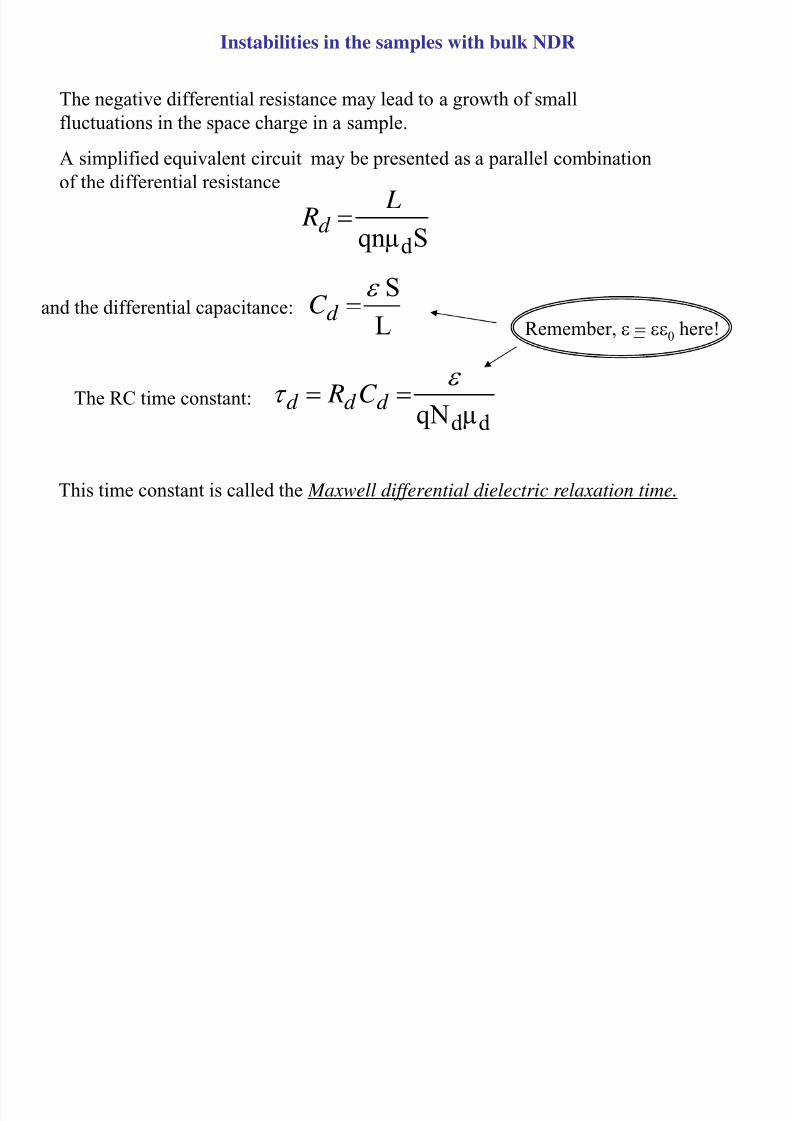
Instabilities in the samples with bulk NDR
The negative differential resistance may lead to a growth of smallfluctuations in the space charge in a sample.
A simplified equivalent circuit may be presented as a parallel combination
of the differential resistance
Sqnµd L Rd =
L
Sε
=d C and the differential capacitance:
d d µqN
ε τ == d d d C RThe RC time constant:
This time constant is called the Maxwell differential dielectric relaxation time.
Remember, ε = εε0 here!
8/19/2019 12 NDR and Gunn Devices
http://slidepdf.com/reader/full/12-ndr-and-gunn-devices 18/24
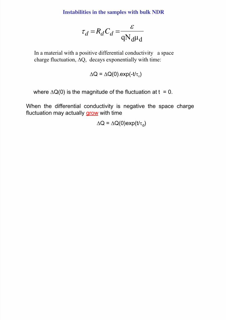
Instabilities in the samples with bulk NDR
d d µqN
ε τ == d d d C R
In a material with a positive differential conductivity a space
charge fluctuation, ∆Q, decays exponentially with time:
∆Q = ∆Q(0).exp(-t/τd)
where ∆Q(0) is the magnitude of the fluctuation at t = 0.
When the differential conductivity is negative the space charge
fluctuation may actually grow with time
∆Q = ∆Q(0)exp(t/τd)
Let the a erage field in the sample be greater than F :
8/19/2019 12 NDR and Gunn Devices
http://slidepdf.com/reader/full/12-ndr-and-gunn-devices 19/24
2
1
3
4
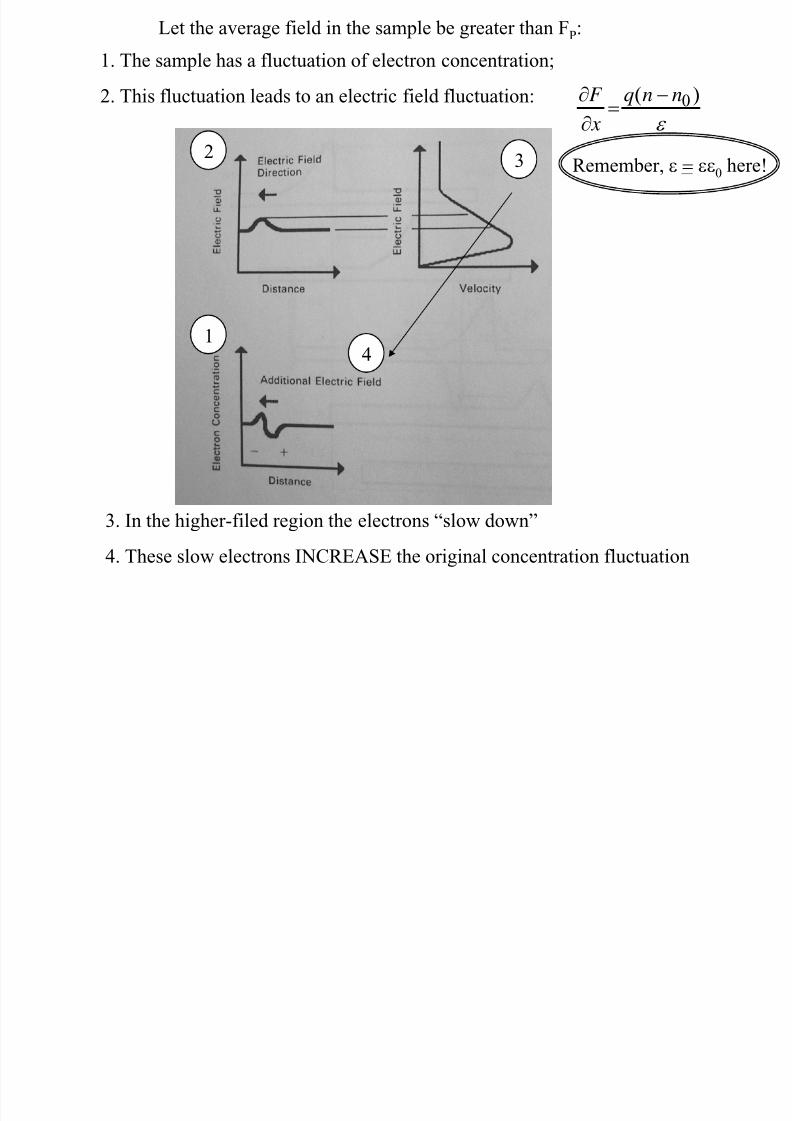
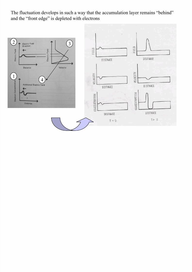
1. The sample has a fluctuation of electron concentration;
2. This fluctuation leads to an electric field fluctuation:
ε
)(0
nnq
x
F −=∂
∂
3. In the higher-filed region the electrons “slow down”
4. These slow electrons INCREASE the original concentration fluctuation
Remember, ε = εε0 here!
Let the average field in the sample be greater than FP:
8/19/2019 12 NDR and Gunn Devices
http://slidepdf.com/reader/full/12-ndr-and-gunn-devices 20/24
The fluctuation develops in such a way that the accumulation layer remains “behind”
and the “front edge” is depleted with electrons
>
2
1
3
4
8/19/2019 12 NDR and Gunn Devices
http://slidepdf.com/reader/full/12-ndr-and-gunn-devices 21/24
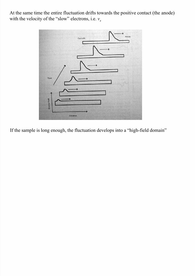
At the same time the entire fluctuation drifts towards the positive contact (the anode)
with the velocity of the “slow” electrons, i.e. vs
If the sample is long enough, the fluctuation develops into a “high-field domain”
8/19/2019 12 NDR and Gunn Devices
http://slidepdf.com/reader/full/12-ndr-and-gunn-devices 22/24
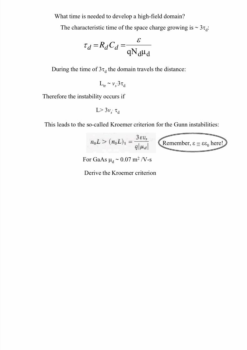
What time is needed to develop a high-field domain?
d d µqN
ε τ == d d d C R
The characteristic time of the space charge growing is ~ 3τd :
During the time of 3τd the domain travels the distance:
Ltr ~ vs.3τd
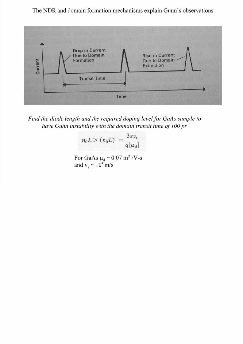
This leads to the so-called Kroemer criterion for the Gunn instabilities:
L> 3vs. τd
Therefore the instability occurs if
For GaAs µd
~ 0.07 m2 /V-s
Remember, ε = εε0 here!
Derive the Kroemer criterion
Wh h l h K i i hi h fi ld d i
8/19/2019 12 NDR and Gunn Devices
http://slidepdf.com/reader/full/12-ndr-and-gunn-devices 23/24
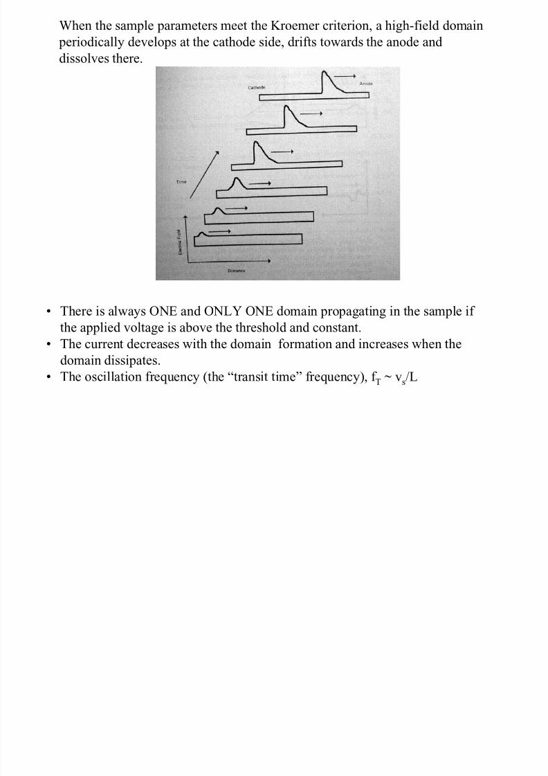
When the sample parameters meet the Kroemer criterion, a high-field domain
periodically develops at the cathode side, drifts towards the anode and
dissolves there.
• There is always ONE and ONLY ONE domain propagating in the sample if
the applied voltage is above the threshold and constant.
• The current decreases with the domain formation and increases when the
domain dissipates.• The oscillation frequency (the “transit time” frequency), f T ~ vs/L
8/19/2019 12 NDR and Gunn Devices
http://slidepdf.com/reader/full/12-ndr-and-gunn-devices 24/24