Embed Size (px)
DESCRIPTION
TECHNICAL
Citation preview

Precast Wall Panel Design
ByEdward Losch, PE, SE

What is a Precast Concrete Sandwich Wall Panel?
Typical Precast Concrete Sandwich Wall Panel

Long-Line Form

Wythe(s) Prestressed

Trucked & Erected (Non-loadbearing)

Load-Bearing Panels

Non-Composite Composite

How are Sandwich Wall Panels Manufactured?

Wet-Cast:
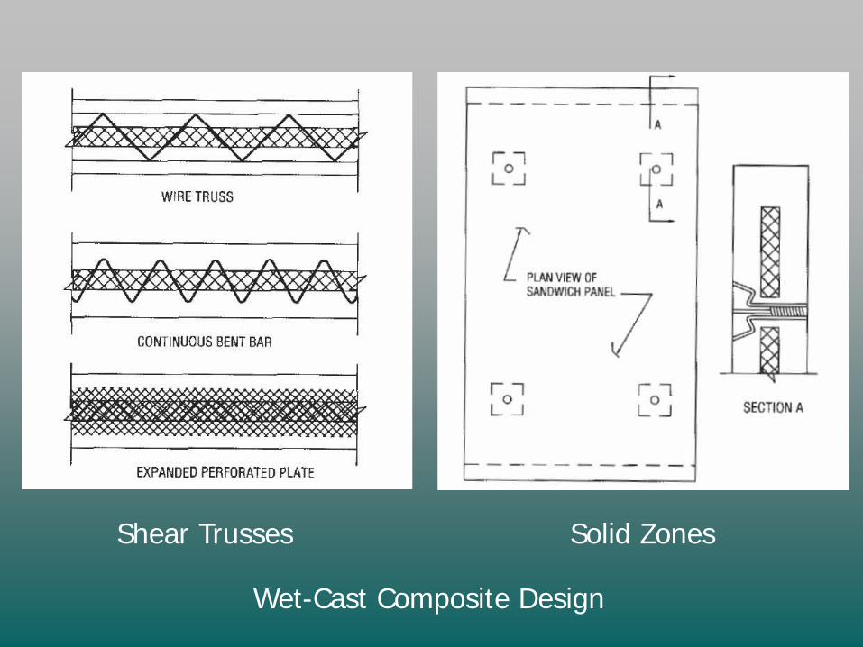
Wet-Cast Composite Design
Shear Trusses Solid Zones

Non-Composite Wythe Connectors

Pin Connectors Inserted in Pre-Drilled Holes

Reveal Strips Glued to Steel Form

Form Liner Located in Panel Form

Panel with Form Liner Impression and Reveals

Cornice Cast Separately, Attached at Site

Sandblasting Panel - Side Lifters Required

Stained Finish

Corewall Panel with Random Rib Finish

Random Rib Finish

Spancrete Non-composite Wall Panel Section
Dry-Cast:
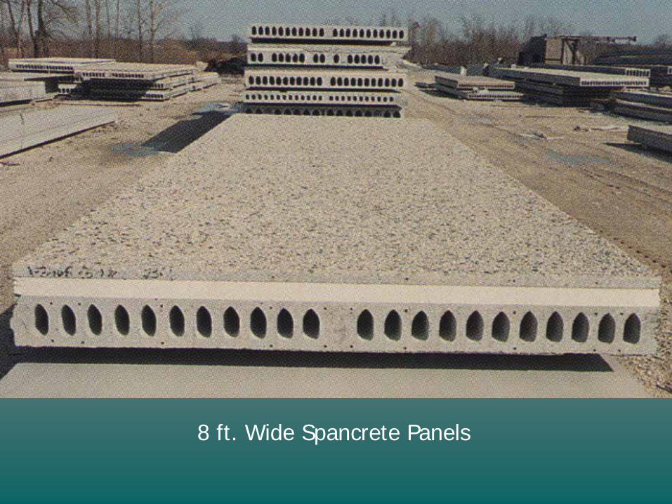
8 ft. Wide Spancrete Panels
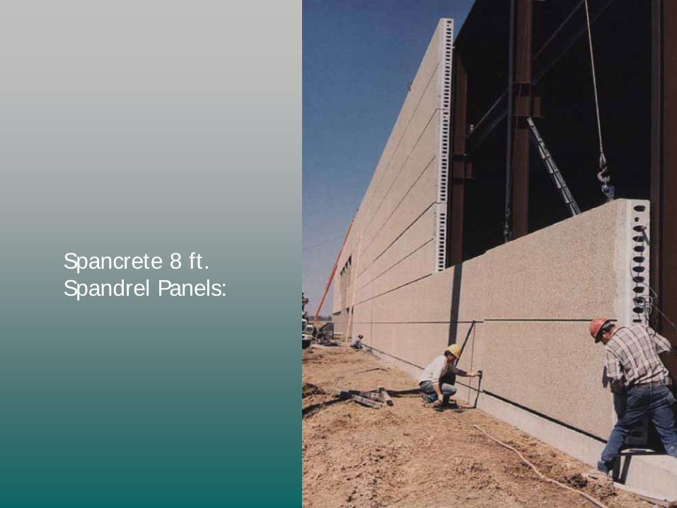
Spancrete 8 ft. Spandrel Panels:

Double-Tee Wall Panel Section

PEC Soundwall

PEC Soundwall form used for Scattered-Site housing in Chicago

Scattered-Site Housing

Scattered-Site Housing

- Expanded Polystyrene, R=4 per inch
- Extruded Polystyrene, R = 5
- Polyisocyanurate, R = 7 to 10
- Phenolic foam: can cause corrosion when wet!
Insulation Types:

Thermal Lag from Concrete Panel Mass

Thermal Lag from Mass of Concrete Panel

Use PCI Mnl 116 (not 117):
“Manual for Quality Control for Plants and Production of Structural Precast Concrete Products”
Manufacturing Tolerances

How are Sandwich Wall Panels Handled & Erected?

Lifter Locations for Stripping & Handling

Yard Storage

Yard Handling with Shuttle-Lift

Trucking Extra-Wide Panelon Slant Frame:

Panels arriving at the Job Site

Single-LineLift

Two-Line Lift

Face Lifters in Form

Top Edge Lifters in Form

Bracing Guidelines:- Use ASCE 7-95 Design Loads- Reduce from 50 yr to 5 yr Re-occurrence- Use 1.5 Factor of Safety for Pipe Braces


Brace to“Deadmen”:


How are Sandwich Wall Panels Designed?

Sandwich Wall Panel with Dock Door Opening - Plan View

Sandwich Wall Panel with Dock Door Opening - Section

Stripping Forces, Shear and Moment Diagrams

Stripping Stresses with 1.4 Handling Factor

Erection Forces, Shear and Moment Diagrams - 2 Line Lift

Erection Stresses with 1.2 Handling Factor

Factored Erection Moments - Ultimate Capacity Check

In-Place Loads forLoad-Bearing Panel:

Applied Loads:
- Wind- Gravity (Roof)- Earth Pressure

Account for Differential Temperature Strains

Service Wind Load Moment Diagram

Service Wind Load Stresses

ACI 318 Section 14.8.4:
The maximum deflection due to service loads, including P-Delta effects, shall not exceed L/150.

Differential Temperature Strain Moment Diagram

Differential Temperature Stresses - Note Panel Bow

Ultimate Capacity Interaction Curves - Dead + Live + Wind

Ultimate Capacity Interaction Curves - Temperature Strain

Relevant ACI 318 Code Sections:
• 14.3.6, 18.11.2.2: Column ties not required when flexural tension controls
• 14.2.7: Maximum height/thickness ratio of 25:1 can be waived when structural analysis is done (P-Delta)
• 14.2.7, 16.4.2, 18.11.2.3: Minimum transverse reinforcement ratio of 0.001 can be used (instead of 0.002)
• 11.10.8: Shear walls do not usually need any shear reinforcement
• 10.11.5: Must use a 2nd order non-linear analysis including cracking when kl/r > 100

Individual LinkedShear Wall Design Examples

Design Tips to Save $$:
- Use repetition to reduce form changes
- Use Precaster’s library of standardconnection details
- Anticipate erection sequence tominimize move-ins
- Use modules for bay spacing:42’ or 48’ for 12’ wide panels40’ or 50’ for 10’ wide panels

Design Tips (continued):
- Punched openings preferred over“pork-chops” and C-shapes:


Hung Panels over Dock

Rabbet at Top of Panel for Bearing Steel Bar-Joist

Continuous Joist Bearing Angle

Individual Joist Bearing Angles

Cast-in Deck Bearing Ledge

Beam Bearing Pocket

Nut-Type Slotted Tie-back Connection with Threaded Rod

Slotted Tie-back Connection with Strap

Knife-Edge Embedded Plates Bearing on Column Haunches

Steel Bearing Tube Haunch in Form

Hung Panel Rotation


Preferred Base Detail to Prevent PotentialWater Infiltration at Floor Level

www.PCI.org312-786-0300
Pub. JR-403

www.PCI.org312-786-0300