Embed Size (px)
Citation preview
-
-
-
-
-
-.
-
SCEPTER12 channel
Rack Mount Mixer
OWNER MANUAL
Allen & Heath Publication: APO093 Issue 3 October 92
OWNER MANUAL

-
-
_
_--
--
--
-
ALLEN & HEATH
This product continues ALLEN & HEATH’s commitment to providehigh quality tools engineered to meet the exacting requirements oftoday’s audio business. It brings you the latest in highperformance technology and offers the reassurance of over twodecades of audio console manufacture and customer support.
Whilst we believe the information in this manual to be correct andreliable we do not assume responsibility for any errors oromissions. We also reserve the right to make changes in theinterest of further product development.
We are able to offer you further product support through ournetwork of approved dealers and service agents. To help usprovide the most efficient service please would you return yourcompleted WARRANTY REGISTRATION card, and enter thefollowing details below to be quoted in any communication
CONSOLE model: I1 serial number: I1
POWER UNIT model: serial number:

-
-
-
-
-
--
-
-
-
-
ALLEN & HEATH BRENELL LTD.
LIMITED ONE YEAR WARRANTYThis product has been manufactured in the UK by ALLEN & HEATHBRENELL LTD and is warranted to be free from defects in materials orworkmanship for a period of one year from the date of purchase by theoriginal owner.
To ensure proper validation and handling of warranty services pleasereturn the WARRANTY REGISTRATION CARD,.
To ensure the high level of performance and reliability for whichthis equipment has been designed and manufactured, please readthe Owner Manual before use.
In the event of a failure notify and return the defective unit to ALLEN &HEATH or its authorised agent as soon as possible for repair underwarranty subject to the following conditions:
CONDITIONS OF WARRANTY:
1. The equipment has been installed and operated in accordance with theinstructions in the Owner Manual,
2. The equipment has not been subject to misuse either intended or accidental,neglect, or alteration other than as described in the Owner/Service Manual,or approved by ALLEN & HEATH.
3. Any necessary adjustment, alteration, or repair has been made by ALLEN8z HEATH or its authorised agent,
4. The defective unit is to be returned carriage prepaid to ALLEN & HEATHor its authorised agent and proof of purchase made available on request,
5. Units to be returned should be packed to avoid transit damage and beaccompanied by the Power Supply Unit.
These terms of warranty apply to UK sales. In other territories the termsmay vary according to legal requirements.
ALLEN & HEATH AGENT: FACTORY:ALLEN & HEATH BRENELL LTDKernick Industrial EstatePenrynCornwall TRlO 9LU
A Harman international Company
Allen & Heath
CONTENTS PAGE
1 ...... INTRODUCTIONGeneral Information . ......................... ................ 1Safety & Precaution .......................................... 2installation ........................................................ 3-4User Service Information ................................... 5Electronic Performance ..................................... 6-7
2 ...... PANEL CONTROL DIAGRAMSInput Channels ................................................. 8-9L/R Section .............. ......................................... 10-11Master Section ........ ......................... ................ 12-13Rear Panel .............. ......................... ................14-16
3 ...... USE OF FACILITIESFRONT PANEL CONTROLSInput Channel Section ....................... ................17-20Left/Right Section ............................................. 21Master Section ........ ......................... ................22-23
4. . . . . . REAR PANEL CONNECTORSInput Channel Section ....................... ................24L/R Section .............. ........................................ ,25-26Master Section ................................................. 27-28D.C. Power connector ....................... ................29
5 ...... USER CONFIGURED OPTIONSAccess to Mixer Circuits .................... ................30-31Options Descriptions ......................... ................32Direct Outputs .................................................. 32Chan Aux Sends .*.a* ......................................... 33-34Stereo Rtn Aux Sends ....................... ................34Mono & Stereo Output ...................................... 35User Options Table ......................................... .36Chassis Ground Isolation .................. ................37
......................................................... ................continued
Allen & Heath
CONTENTS continued PAGE
-
6 . . . . . . SERVICE INFORMATIONDIAGRAMSMain IDC Ribbon Connector . . . . . . . . . ...* ..*...,.........Dimensions Diagram . . . . . . . . . ..*......*...... ..*.....*.*..*..System Block Diagram .,..*.*..*.....*..,... . . . . . . . ...*.....
-
7...... SCHEMATIC DIAGRAMSInput Components and Option Placement.. .......Input Circuit Diagram ........................ ................Left / Right Components and Option Placement
-_
...
Left / Right Circuit Diagram ............... ................Master Components and Option Placement.. ....Master Circuit Diagram...................... ................EBOS Components & Circuit Diagram.. .............Power Supply Components & Circuit Diagram . .
-

Audio Owner Manual Section 1
-
-
-
INTRODUCTION
The Allen & Heath SCEPTER RACK MOUNT MIXER is a versatile,economical and easy-to-use general purpose rack mount mixer intended for stereoand mono PA applications as well as stereo recording. The quality of design,construction and components employed will ensure high performance in theseapplications when correctly used. Operators and installers are encouraged to studythe contents of this handbook.
Construction:
1. Aluminum front panel, stove enamel, enamel silk-screened legend.2. Steel Rear Panel and Chassis, grey stove enamel finish.3. Individual Channel assemblies secured to Front and Rear panels.4. Internal busbar circuits employ removable IDC harness.5. Glass-epoxy circuits cards for strength and reliablity6. All audio path ICs are socketed for ease of service.7. IC op-amp and discrete component circuit design.
AC Power Requirements:
Allen & Heath power supplies MPS8-R (Supplied), MPS8-P, MPS9, and RPS-1provide the necessary DC power for the mixer. These are the only power suppliesrecommended for use with this product. Use of power supplies other than thosespecified may void the mixer warranty. All Allen & Heath power supplies operate onthe following mains voltages/frequencies -
220-240V AC 50/60 Hz 50VA Europe11 O-1 20V AC 50/60 Hz USA100 Volt AC 50/60 Hz 50VA Japan
NOTE: The MPS-8R power supply is provided as standard with the Scepter.providing +15 Volts and -15 Volts for mixer operation, and +48 Volts for PhantomPower microphone operation. It is configured as a Rack Mount Power Supply forstandard 19” racks. If necessary the Front Panel may be removed to enable remotemounting.
Further details on mains voltages are available within the SERVICE section ofthis manual.
1

Audio Owner Manual Section 1
Mains electricity is dangerous and can kill. Mains voltage is present within thepower unit but not the Scepter unit. Check your mains wiring and earthing beforeconnecting up and switching on.
The purpose of the “earth” (ground) connection in a mains supply is for theprevention of electric shock from the mains voltage present. It is usual for thechassis of mains powered equipment to be connected to earth to prevent the metalparts becoming “live” and causing electric shock. Some are “double insulated” anddo not require an earth connection.
The Scepter power supply (MPS-8R) must be connected to a suitable mainsearth through the designated earth wire in the mains cord.
The power supply mains earth is not connected to the Scepter earth. The unitshould be connected via a different path to mains earth. (see CHASSIS GROUNDLIFT section)
Equipment will continue to function if it is not connected to mains earth.This does not mean that it is safe. GOVERNMENT AND INSURANCEUNDERWRITERS ELECTRICAL CODES MUST BE OBSERVED. These codestake precedence over any suggestions in this manual.
2
-Audio Owner Manual Section 1
- INSTALLATION
-
Unpack the unit from the packing carton. Remove the power supply unit fromthe packing. We recommend that you keep intact this purpose designed packing toreuse should you need to ship the unit in the future. Please ensure that the Scepterunit, power supply and other items are correctly repacked to avoid transit damage.Please ensure that the fader knobs are in the up position.
.- Check that the AC operating voltage marked on the power unit is the same asthe local supply.
-
--
Connect the DC power cord from the power supply into the rear panel of theScepter unit. Ensure that it latches firmly.
._Earthing/Grounding in the audio system
There two important reasons why it is necessary to ensure that your audiosystem is well earthed (grounded).
1) Safety - prevention of electric shock (see previous section on SAFETY)2) Shielding - preventing external electrical interference from causing noise in the
audio signal path.
-
In addition to solving noise and interference problems, earthing can alsocause them. If there are multiple earth paths in a system then an “earth loop” canbe formed. This usually results in an excess hum in the system, but can also causethe breakthrough of RF and other noises.
-
-
The preferred method to overcome earth loop problems is to earth all piecesof equipment separately to a good “star point” mains earth and to break potentialearth loops by disconnecting the screens of the audio cables at one end, usuallythe signal destination. If excessive RF interference is present this may be reducedby connecting the screen to earth through a small value capacitor, typically 0.01microfarad
-
-
.-
Alternatively; just one piece of equipment, usually the power amplifier, isconnected to mains earth and the other equipment earthed via the interconnectingcable screens which must be connected at both ends. However, having only oneunit connected to mains earth means that all of the other pieces of equipment relyon the audio cable screen for safety. It is important to remember this. Testregularly, that all exposed metal equipment including microphones, guitar stringsand DI boxes have a low resistance to mains earth.
3
Audio Owner Manual Section 1
The console is not connected to mains earth for the reasons mentioned aboveand under normal operating conditions it contains no dangerous voltages. Thepower supply chassis is connected to mains earth and must never bedisconnected. Likewise never disconnect the earth wire in the mains plug.
It is best to plan ahead and have your installation checked by a competentengineer before you commence. Do not trust equipment and installations modifiedby others.
4
Audio Owner Manual Section 1-
- USER SERVICE INFORMATION
.-There are no adjustments or alignment procedures required to maintain the
performance standards of this Allen & Heath product.
To preserve the working life of the unit and its presentation, avoid the use ofchemicals, abrasives and solvents. The control panel is best cleaned with a softbrush and a damp cloth. Switches and potentiometers are lubricated for life; theapplication of electrical lubricants to these parts is not recommended.
-A number of user options are available. These are changes to the functions of
various controls and outputs which can be altered by the user repositioning internaljumper links. The details of these options are covered under in USERCONFIGURED OPTIONS section of this manual. Any modifications to the unit otherthan those specifically listed will automatically void the warranty.
.-
Audio Owner Manual Section 1
ELECTRONIC PERFORMANCE
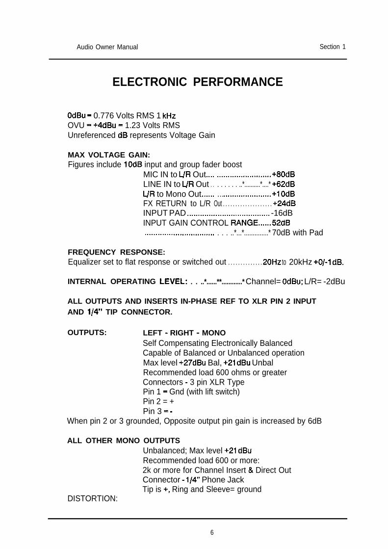
OdBu - 0.776 Volts RMS 1 kHzOVU = +4dBu = 1.23 Volts RMSUnreferenced dB represents Voltage Gain
MAX VOLTAGE GAIN:Figures include 10dB input and group fader boost
MIC IN to L/R Out,.., ,,,.........I*.........*. +80dBLINE IN to L/R Out . . . . . . . . ..*..........*....* +62dBL/R to Mono Out..,.,. . . . ..**......*.......s.*. +1 OdBFX RETURN to L/R Out . . . . . . . . . . . . . . . . . . . . +24dBINPUT PAD ..a.....,.... ,,,...................... -16dBINPUT GAIN CONTROL RANGE......52dB.*.............**...*.....***... . . . ..*...*..............* 70dB with Pad
FREQUENCY RESPONSE:Equalizer set to flat response or switched out . . . . . . . . . . . . . . 20Hz to 20kHz +0/-l dB.
INTERNAL OPERATING LEVEL=. . . ..*......**............* Channel= OdBu; L/R= -2dBu
ALL OUTPUTS AND INSERTS IN-PHASE REF TO XLR PIN 2 INPUTAND l/4” TIP CONNECTOR.
OUTPUTS: LEFT - RIGHT - MONOSelf Compensating Electronically BalancedCapable of Balanced or Unbalanced operationMax level +27dBu Bal, +2ldBu UnbalRecommended load 600 ohms or greaterConnectors - 3 pin XLR TypePin 1 = Gnd (with lift switch)Pin 2 = +Pin 3 = -
When pin 2 or 3 grounded, Opposite output pin gain is increased by 6dB
ALL OTHER MONO OUTPUTSUnbalanced; Max level +21 dBuRecommended load 600 or more:2k or more for Channel Insert & Direct OutConnector - l/4” Phone JackTip is +, Ring and Sleeve= ground
DISTORTION:
6
- +a
Audio Owner Manual Section 1-
- ELECTRONIC PERFORMANCE continued
-THD typically better than 0.04%20Hz-20kHz at ‘normal levels and gain settings
--NOISE PERFORMANCE: RMS noise 20kHz bandwidth
L or R Output(all input faders closed)-83dBuL or R Output(1 input @ unity gain)-83dBuAux Outputs(Unity gain)-90dBuMicrophone Input equivalent noise-l 27dBu (200 Source)
- 7
Audio Owner Manual Section 2
LINE
L-J PAD-
AUX SENDS
HF - 0 +
MID - ? +
E
IIIEQ IN
FRONT PANEL CONTROLS.
INPUT CHANNEL
1.
2.
3.
4.
5.
6.
7.
6.
9.
10.
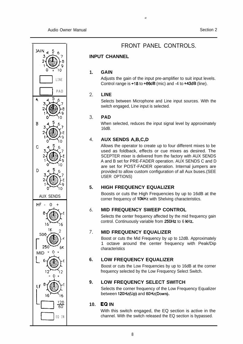
GAINAdjusts the gain of the input pre-amplifier to suit input levels.Control range is +18 to +66dB (mic) and -4 to +43dB (line).
LINESelects between Microphone and Line input sources. With theswitch engaged, Line input is selected.
PADWhen selected, reduces the input signal level by approximately16dB.
AUX SENDS A,B,C,DAllows the operator to create up to four different mixes to beused as foldback, effects or cue mixes as desired. TheSCEPTER mixer is delivered from the factory with AUX SENDSA and B set for PRE-FADER operation. AUX SENDS C and Dare set for POST-FADER operation. Internal jumpers areprovided to allow custom configuration of all Aux buses.(SEEUSER OPTIONS)
HIGH FREQUENCY EQUALIZERBoosts or cuts the High Frequencies by up to 16dB at thecorner frequency of 1OkHz with Shelving characteristics.
MID FREQUENCY SWEEP CONTROLSelects the center frequency affected by the mid frequency gaincontrol. Continuously variable from 250Hz to 6 kHz.
MID FREQUENCY EQUALIZERBoost or cuts the Mid Frequency by up to 12dB. Approximately1 octave around the center frequency with Peak/Dipcharacteristics
LOW FREQUENCY EQUALIZERBoost or cuts the Low Frequencies by up to 16dB at the cornerfrequency selected by the Low Frequency Select Switch.
LOW FREQUENCY SELECT SWITCHSelects the corner frequency of the Low Frequency Equalizerbetween 12OHz(Up) and GOHz(Down).
EQ INWith this switch engaged, the EQ section is active in thechannel. With the switch released the EQ section is bypassed.
8
-
Audio Owner Manual Section 2-
-
-
-
-
PFL
B PEAK&IG 0 *
1
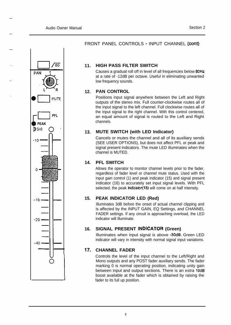
FRONT PANEL CONTROLS - INPUT CHANNEL (cant)
11. HIGH PASS FILTER SWITCHCauses a gradual roll off in level of all frequencies below 80Hzat a rate of -12dB per octave. Useful in eliminating unwantedlow frequency sounds.
12. PAN CONTROLPositions input signal anywhere between the Left and Rightoutputs of the stereo mix. Full counter-clockwise routes all ofthe input signal to the left channel. Full clockwise routes all ofthe input signal to the right channel. With this control centered,an equal amount of signal is routed to the Left and Rightchannels.
13. MUTE SWITCH (with LED Indicator)Cancels or mutes the channel and all of its auxiliary sends(SEE USER OPTIONS), but does not affect PFL or peak andsignal present indicators. The mute LED illuminates when thechannel is MUTED.
14. PFL SWITCHAllows the operator to monitor channel levels prior to the fader,regardless of fader level or channel mute status. Used with theinput gain control (1) and peak indicator (15) and signal presentindicator (16) to accurately set input signal levels. With PFLselected, the peak indicator(l5) will come on at half intensity.
15. PEAK INDICATOR LED (Red)Illuminates 3dB before the onset of actual channel clipping andis affected by the INPUT GAIN, EQ Settings, and CHANNELFADER settings. If any circuit is approaching overload, the LEDindicator will illuminate.
16. SIGNAL PRESENT INDICAT.OR (Green)Illuminates when input signal is above -3OdB. Green LEDindicator will vary in intensity with normal signal input variations.
17. CHANNEL FADERControls the level of the input channel to the Left/Right andMono outputs and any POST fader auxiliary sends. The fadermarking 0 is normal operating position, indicating unity gainbetween input and output sections. There is an extra 1OdBboost available at the fader which is obtained by raising thefader to its full up position.
9
Audio Owner Manual Section 2
MONITOR L+6
+3
-0-3
-6
-9
-12
-15
-18-21
L R
L-J PFL
EFX RETURNS
L R
I PFL
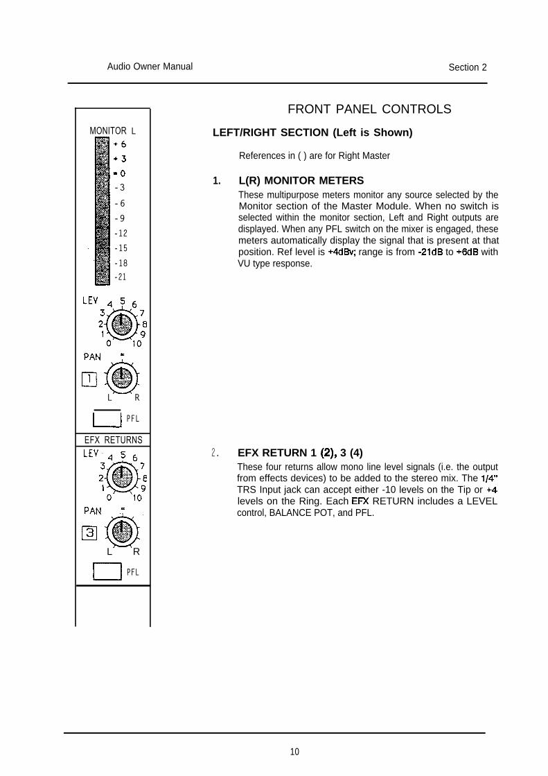
FRONT PANEL CONTROLS
LEFT/RIGHT SECTION (Left is Shown)
References in ( ) are for Right Master
1. L(R) MONITOR METERSThese multipurpose meters monitor any source selected by theMonitor section of the Master Module. When no switch isselected within the monitor section, Left and Right outputs aredisplayed. When any PFL switch on the mixer is engaged, thesemeters automatically display the signal that is present at thatposition. Ref level is +4dBv; range is from -2ldB to +6dB withVU type response.
2. EFX RETURN 1 (2), 3 (4)These four returns allow mono line level signals (i.e. the outputfrom effects devices) to be added to the stereo mix. The l/4”TRS Input jack can accept either -10 levels on the Tip or +4levels on the Ring. Each ER( RETURN includes a LEVELcontrol, BALANCE POT, and PFL.
10
-Audio Owner Manual Section 2
-
-
-
-
-
-
-
E lMONO
L R
MUTE
STEREO RTN 1
PFL
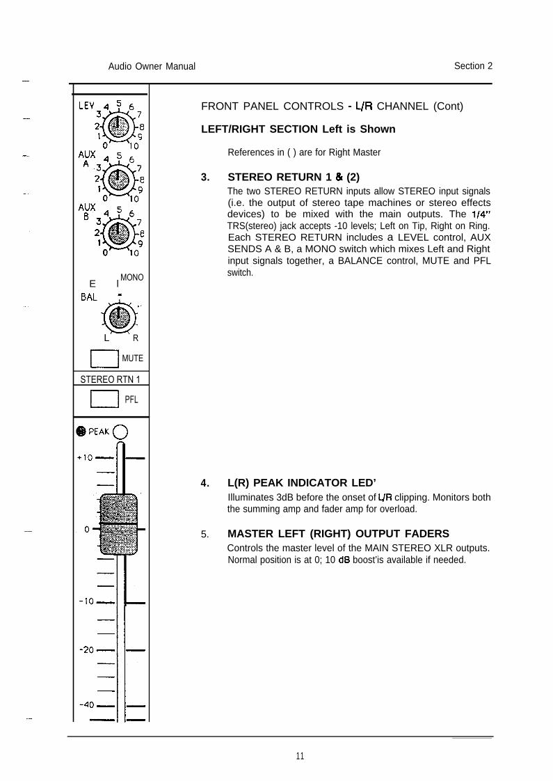
FRONT PANEL CONTROLS - L/R CHANNEL (Cont)
LEFT/RIGHT SECTION Left is Shown
References in ( ) are for Right Master
3. STEREO RETURN 1 & (2)The two STEREO RETURN inputs allow STEREO input signals(i.e. the output of stereo tape machines or stereo effectsdevices) to be mixed with the main outputs. The l/4”TRS(stereo) jack accepts -10 levels; Left on Tip, Right on Ring.Each STEREO RETURN includes a LEVEL control, AUXSENDS A & B, a MONO switch which mixes Left and Rightinput signals together, a BALANCE control, MUTE and PFLswitch.
4. L(R) PEAK INDICATOR LED’Illuminates 3dB before the onset of L/R clipping. Monitors boththe summing amp and fader amp for overload.
5. MASTER LEFT (RIGHT) OUTPUT FADERSControls the master level of the MAIN STEREO XLR outputs.Normal position is at 0; 10 dB boost’is available if needed.
11
Audio Owner Manual Section 2
12vLAMP
B 1-j +48
D PWRON
A
B 4 5 6
AUX MASTERS
STEREO OUT
MUTE
MONO OUT
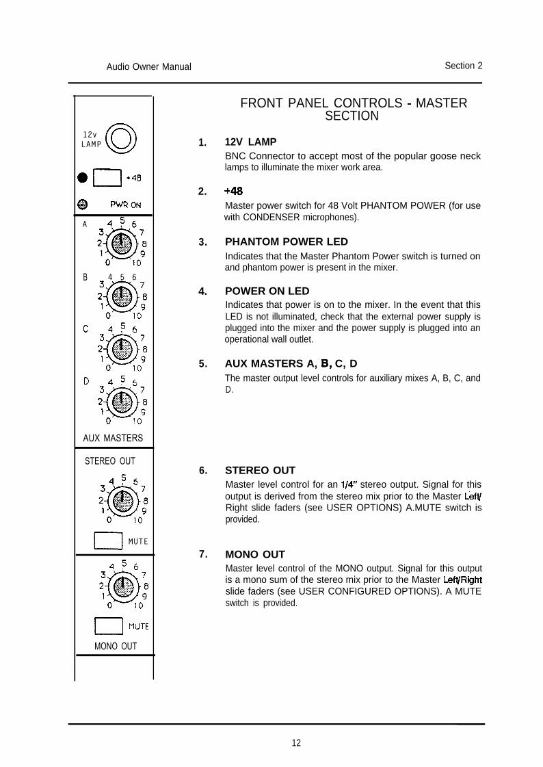
1. 12V LAMPBNC Connector to accept most of the popular goose necklamps to illuminate the mixer work area.
2. +46Master power switch for 48 Volt PHANTOM POWER (for usewith CONDENSER microphones).
3. PHANTOM POWER LEDIndicates that the Master Phantom Power switch is turned onand phantom power is present in the mixer.
4. POWER ON LEDIndicates that power is on to the mixer. In the event that thisLED is not illuminated, check that the external power supply isplugged into the mixer and the power supply is plugged into anoperational wall outlet.
5. AUX MASTERS A, 8, C, DThe master output level controls for auxiliary mixes A, B, C, andD.
6. STEREO OUTMaster level control for an l/4” stereo output. Signal for thisoutput is derived from the stereo mix prior to the Master LeftIRight slide faders (see USER OPTIONS) A.MUTE switch isprovided.
7. MONO OUT
FRONT PANEL CONTROLS - MASTERSECTION
Master level control of the MONO output. Signal for this outputis a mono sum of the stereo mix prior to the Master LefVRightslide faders (see USER CONFIGURED OPTIONS). A MUTEswitch is provided.
12
-
Audio Owner Manual Section 2
-
-
-
-
-
-
-
AUXA
0AUX
B
AUXC
AUXD
1-1 MONOI J
MONITORSELECT
@ PFL O N
SCEPTERRACK
HEADPHONES
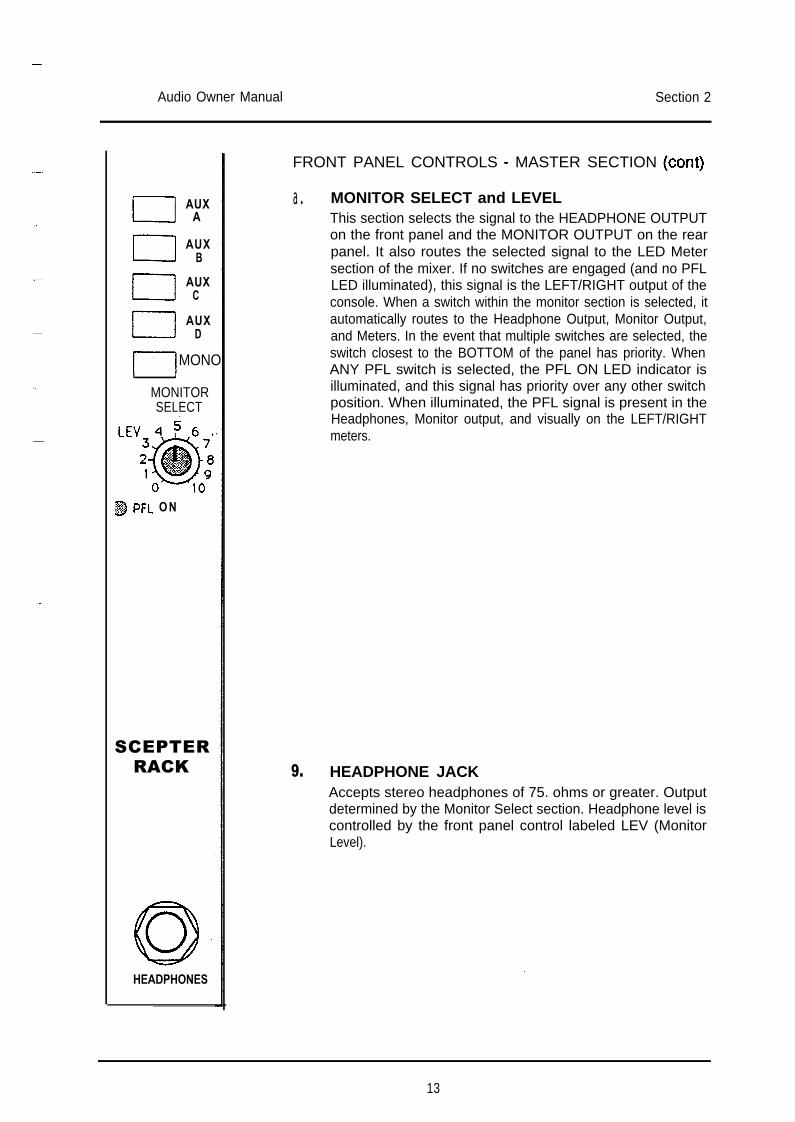
FRONT PANEL CONTROLS - MASTER SECTION (cant)
a. MONITOR SELECT and LEVELThis section selects the signal to the HEADPHONE OUTPUTon the front panel and the MONITOR OUTPUT on the rearpanel. It also routes the selected signal to the LED Metersection of the mixer. If no switches are engaged (and no PFLLED illuminated), this signal is the LEFT/RIGHT output of theconsole. When a switch within the monitor section is selected, itautomatically routes to the Headphone Output, Monitor Output,and Meters. In the event that multiple switches are selected, theswitch closest to the BOTTOM of the panel has priority. WhenANY PFL switch is selected, the PFL ON LED indicator isilluminated, and this signal has priority over any other switchposition. When illuminated, the PFL signal is present in theHeadphones, Monitor output, and visually on the LEFT/RIGHTmeters.
9. HEADPHONE JACKAccepts stereo headphones of 75. ohms or greater. Outputdetermined by the Monitor Select section. Headphone level iscontrolled by the front panel control labeled LEV (MonitorLevel).
13
Audio Owner Manual Section 2
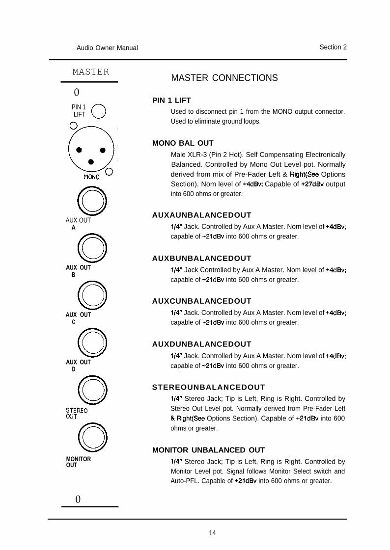
MASTERMASTER CONNECTIONS
0PIN 1 LIFT
PIN 1LIFT 0, Used to disconnect pin 1 from the MONO output connector.
Used to eliminate ground loops.
MONO BAL OUTMale XLR-3 (Pin 2 Hot). Self Compensating ElectronicallyBalanced. Controlled by Mono Out Level pot. Normallyderived from mix of Pre-Fader Left & Right(See OptionsSection). Nom level of +4dBv; Capable of +27dBv outputinto 600 ohms or greater.
AUX OUTA
0AUX OUT
B
0AUX OUT
C
Q3AUX OUT
D
0
EREO
0MONITOROUT
0
AUXAUNBALANCEDOUTl/4” Jack. Controlled by Aux A Master. Nom level of +4dBv;capable of +2ldBv into 600 ohms or greater.
AUXBUNBALANCEDOUTl/4” Jack Controlled by Aux A Master. Nom level of +4dBv;capable of +2ldBv into 600 ohms or greater.
AUXCUNBALANCEDOUTl/4” Jack. Controlled by Aux A Master. Nom level of +4dBv;capable of +2ldBv into 600 ohms or greater.
AUXDUNBALANCEDOUTl/4” Jack. Controlled by Aux A Master. Nom level of +4dBv;capable of +2ldBv into 600 ohms or greater.
STEREOUNBALANCEDOUTl/4” Stereo Jack; Tip is Left, Ring is Right. Controlled byStereo Out Level pot. Normally derived from Pre-Fader Left& Right(See Options Section). Capable of +2ldBv into 600ohms or greater.
MONITOR UNBALANCED OUTl/4” Stereo Jack; Tip is Left, Ring is Right. Controlled byMonitor Level pot. Signal follows Monitor Select switch andAuto-PFL. Capable of +2ldBv into 600 ohms or greater.
14
Audio Owner Manual Section 2
-
-
-
LEFT
__EFX RTN
EFX RTN3
STR RTN1
Q LINSERT
Q LBUS IN
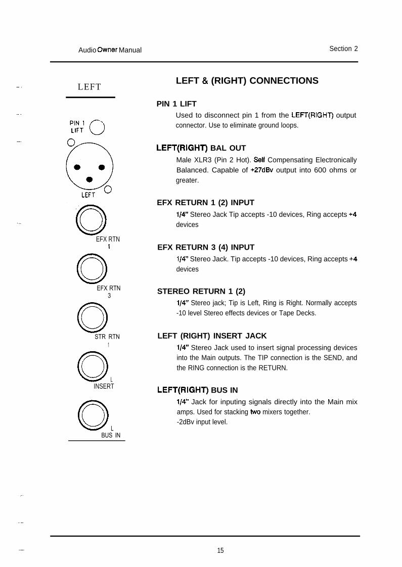
LEFT & (RIGHT) CONNECTIONS
PIN 1 LIFTUsed to disconnect pin 1 from the LEFT(RIGHT) outputconnector. Use to eliminate ground loops.
LEFT(RIGHT) BAL OUTMale XLR3 (Pin 2 Hot). Seff Compensating ElectronicallyBalanced. Capable of +27dBv output into 600 ohms orgreater.
EFX RETURN 1 (2) INPUTl/4” Stereo Jack Tip accepts -10 devices, Ring accepts +4devices
EFX RETURN 3 (4) INPUTl/4” Stereo Jack. Tip accepts -10 devices, Ring accepts +4devices
STEREO RETURN 1 (2)l/4” Stereo jack; Tip is Left, Ring is Right. Normally accepts-10 level Stereo effects devices or Tape Decks.
LEFT (RIGHT) INSERT JACKl/4” Stereo Jack used to insert signal processing devicesinto the Main outputs. The TIP connection is the SEND, andthe RING connection is the RETURN.
LEFT(RIGHT) BUS INl/4” Jack for inputing signals directly into the Main mixamps. Used for stacking two mixers together.-2dBv input level.
_- 15

Audio Owner Manual Section 2
INPUT
INSERT
DIRECTOUT
INPUT CHANNELS
INDIVIDUAL PHANTOM POWER SWITCHWhen engaged, turns on the +48v phantom power for thatchannel if the Master +43v switch on Front Panel is on.
MIC INPUT CONNECTOR3-pin Female XLR connector used to connect balanced low(mic) level signals into the channel.
LINE INPUT JACKBalanced l/4” stereo jack used to connect high (line) levelsignals into the channel. Will accept balanced or unbalancedsignals.
CHANNEL INSERT JACKl/4” Stereo Jack used to insert signal processing devicesinto the channel. The TIP connection is the SEND, and theRING connection is the RETURN.
CHANNEL DIRECT OUTl/4” Jack for Individual Channel out signals. Normally set asPost-Fader/Post-Mute.
16
-
-Audio Owner Manual Section 3
- USING THE SCEPTER SERIES MIXER
-THE INPUT CHANNEL
-
-
The input channel accepts a balanced or unbalanced input signal from amicrophone, direct box or a line level source such as the output of a synthesizer, orexternal signal processing device such as a digital delay line, reverb, etc.
Phantom Power 1The SCEPTER Series Mixers are factory wired for the +48 volt DC. phantom
powering of condenser microphones. When the master phantom power switch is onand the individual channel phantom switch is on, +48 volts is present at XLR pins 2and 3. Power supplies MPS8-R, MPS8-P, MPS9 and RPSl provide the necessaryvoltage. The master phantom power pushbutton switch is located at the top of themaster section on the front panel. The individual channel phantom power onswitches are located on the rear panel above the MIC connectors and can beactivated with a pencil or similar object.
NOTE: When using phantom power it is important to avoid connecting anUNBALANCED signal source to the MICROPHONE input without havingfirst switched off the phantom power to that channel.
Input Gain ControlThe input gain control is used to vary the gain of the ‘input preamp. Control
range is +2dB to +66dB for MIC and -2OdB to +44dB for LINE. These figuresinclude the effect of the PAD switch.
Line SwitchWhen depressed, this switch selects the Balanced Line Input (l/4” stereo
jack). as the source for the Channel. The Balanced Mic input (3 pin XLR) isselected when the switch is in the UP position.
Input Pad SwitchOn occasion, situations may arise where high level signal sources (a live kick
drum, or some drum machines and synths) overload the input channel, even thoughthe input gain control is set at minimum. Engaging the PAD switch reduces theincoming mic or line signal by 16dB. Should the amount of attenuation prove to beexcessive, the input gain control can be raised to bring the signal level up to thedesired level. The PFL system can be very useful here, and should be employed toset channel gain to the proper level.
- 17
Audio Owner Manual Section 3
Channel Auxlliary SendsEach Scepter input channel features four auxiliary send controls. These
controls feed auxiliary masters A, B, C and D and allow the user to create fouradditional mixes of the signal sources fed to the mixer. These mixes are generallyused as feeds to external FX devices, as foldback mixes to an onstage monitorsystem, or as a cue mix for performers headphones in recording situations.
Aux A and B are normally PRE-EQ feeds to the Aux A and B mixes. Thesemixes are unaffected by channel EQ settings and fader position and may be usedas feeds to an on-stage monitoring system. It should be noted that whilst thesemixes are not affected by changes in the EQ settings, they ARE affected bychanges made at the input gain control, and changes made there may require thata proportional change be made at the aux send.
Aux C and D are normally POST-FADER feeds to the Aux C and D mixes.Their operation is dependent on the level of the channel fader and will changeproportionally with fader movements and will be cut off when the mute switch isactivated. For this reason, these mixes are normally used to feed external FXdevices.
SCEPTER Series mixers have been wired in this configuration at manufacture.However provision has been made within the mixer which allow the user to choosethe point in the channel circuit from which the aux level control derives its source.For further information, see USER CONFIGURED OPTIONS section.
EqualizerThe channel EQ allows you to alter the tone and harmonic balance of the
signal in the channel. You can filter out unwanted high frequency noise (hiss), orlow frequency noise (rumble), and compensate for deficiencies in oldermicrophones or problems with your acoustic environment.
High Frequency EqualizerThis control either boosts or cuts the high frequency content of the signal
source by up to 16dB at 1OkHz and above, having progressively less effect atfrequencies below 1OkHz. This is known as a shelving type equalizer. At its centreposition the control has a flat response and no effect on the high frequency content.
Mid Frequency SelectThis control tunes the mid centre frequency between 250Hz and 6kHz.
18
Audio Owner Manual Section 3
Mid Frequency EqualizerThis control provides 12dB of boost or cut at the frequency selected by the
Mid Select control. This is a peak/dip type equalizer. It affects sounds both aboveand below the selected frequency within a range of approximately one octave(Q-l .4). This means that boosting the mid equalizer at 2k affects not only 2k butalso the frequencies surrounding it, but to a lesser degree. This control has noeffect on the signal when set to the centre flat position.
Low Frequency Equalizer- This control boosts or cuts the low frequency content of the signal source, by
up to 16dB, below 60 Hz or 120 Hz depending on the position of the low frequencyselect switch. It has a shelving characteristic and at its centre position the controlhas no effect on the low frequency content.
Low Frequency Select SwitchThis switch is used to select the frequencies affected by the Low Frequency
Equalizer. In the up position, a corner frequency of 120Hz is selected; whenengaged, 60Hz is selected.
Eq In SwitchThis switch is used to activate the EQ section in the channel signal path.
When the switch is in the up position, the channel signal bypasses the EQ section.
Hi Pass Filter SwitchDepressing this switch engages an 80Hz, -12dB/octave filter. This filter is
independent of the 3-band channel EQ and is useful for eliminating stage rumble,wind noise and other low frequency sounds.
Pan ControlThe input signal can be placed anywhere in the stereo image by turning the
PAN to the right or the left. When the pan control is turned fully left, the input signalis routed to the left stereo output only. Turned fully right, the signal is routed to theright stereo output. When the PAN is in the centre position, the signal is equal inlevel to both the left and the right.
Mute Switch
-
When depressed, this switch mutes or cancels the signal from the channelafter the channel fader. It also mutes signals going to any Aux mixes. An optionallows the Pre-EQ Aux source to be unaffected by the MUTE switch (See USERCONFIGURED OPTIONS section.)
- 19
Audio Owner Manual Section 3
PFL Button (Pm-Fader Llsten)Engaging the PFL allows you to listen to the Pre-Fader signal in the monitor
and headphone outputs. The PFL system takes its signal after the EQ section butbefore the channel fader. This allows you to make signal level and quality checksbefore bringing up the channel in the mix. When a PFL switch is engaged, the L/Rmeters will indicate the PFL level; the channel PEAK Indicator will illuminate at halfintensity; and the PFL indicator in the master section will illuminate.
Peak signal IndicatorThis red LED illuminates when channel audio signals approach overload. The
peak detection circuit samples the signal after the preamp, after the equaliser andafter the fader so revealing risk of overload at all stages.
Signal present IndicatorThis green LED monitors the signal at the output of the channel preamp. The
intensity will vary with the strength of the channel signal starting at -3OdBu andreaching a constant intensity when the signal reaches approx OdBu. The EQ, faderand mute settings will not affect the LED.
Channel FaderUsed to alter the level of an individual channel in the mix. Normal operating
position is at the 0 mark. However, an extra 1OdB boost can be obtained with thefader fully up. Also provides the signal feed to AUX mixes selected for POSTFADER operation.
20
Audio Owner Manual Section 3
LEFT/RIGHT SECTION
L/R Monitor MetersEach meter is a IO segment LED display which provide a visual indication of
the source selected by the monitor select switches. Calibrated in 3dB steps from-21dB to +6dB, each meter is a VU type(average) responding meter with the 0position indicating an output level of +4dBu (1.23~ RMS).
EFX Returns 1,2,3,4-- By use of the control marked LEVel these inputs can be used to bring signals
from external effects devices back into the stereo mix. A PAN control is used toplace the signals within the stereo image as desired. A PFL switch allows you tomonitor the EFX return signal prior to its level control. The EFX RTN jack isconfigured to provide either unity return gain or +12dB return gain. For low level(-1OdBV) devices, the return plug should be inserted all the way into the jacksocket: this provides 12dB extra gain. For high level (+4dBu) devices, insert theplug halfway into the EFX RTN jack to provide unity gain. Alternatively, use a stereojack plug and connect the input signal to the ring contact. Use the EFX PFL switchto help determine the proper position if not certain.
Stereo Return l/2
-
Two independent low level (-1OdBV) stereo inputs are provided for return tapeor stereo effects into the L/R mix. Sends A & B are available for mixing the signal tothe Aux buses for wet monitoring. These sends are normally set up as pre-levelmono. Internal jumper links can be altered to reconfigure the sends as post-levelstereo (left to Aux A, right to Aux B) if desired.(See USER CONFIGURED OPTIONSsections). The BALance control positions the Stereo Return signal in the L/R mixwith up to 6dB cut. The MONO switch mixes the Left(tip) and Right(ring) inputstogether and changes the BALance control to a normal PAN control. The MUTEswitch cuts the signal to L/R and to any Aux sends set for Post-level. The PFLswitch allows the operator to monitor the Return independently of the LEVel control.
L/R Peak Indicator LED
-
Warns of imminent overload distortion (3dB below clipping) when the signallevel in L/R approaches this threshold. The circuit monitors both the tJR mix ampand line amp; even if the fader is down, you will still be notified of mix ampoverload.
L/R Output FadersControls the level of the stereo mix to the L/R Balanced outputs.
- 21
Audio Owner Manual Section 3
MASTER SECTION
12V LampThis BNC Connector will accept 12 volt D.C. goose neck lamps rated at 50mA
to 150mA current consumption. Used to illuminate the mixer work area.
+48Master power switch for +48 Volt PHANTOM POWER (for use with
CONDENSER microphones). When this switch is depressed, the LED will illuminateindicating that power is supplied to any channel whose individual Phantom switch ison.
Power on LEDIndicates that power is being supplied to the mixer. In the event that this LED
is not illuminated, check that the external power supply is plugged into the mixerand the power supply is plugged into an operational wall outlet.
Aux Masters A, B, C, DThe master output level controls for auxiliary mixes A, B, C, and D. For
optimum performance (i.e. lowest noise), these controls should be set at 7 and theindividual channel sends should be set as high as possible.
Stereo OutMaster level control for the stereo output l/4” jack socket. Signal for this
output is derived from the Pre-Insert stereo mix prior to the Left/Right faders. Aswitch is provided to Mute this output when desired. Use this control when anindependent output is needed for a video or tape feed. Post-Insert and Post-Faderselections are also possible.(see USER CONFIGURED OPTIONS section)
Mono OutMaster level control of the MONO output. Signal for this output is a mono sum
of the Pre-Insert stereo mix prior to the Left/Right faders. A MUTE switch is alsoprovided for this output. Post-Insert and Post-Fader selections are alsopossible.(see USER CONFIGURED OPTIONS section)
22
I-
h
h..
w.-
-
-
-
-
-
-
Audio Owner Manual Section 3
Monitor Select and LevelThis section selects the signal for the HEADPHONE OUTPUT on the front
panel and the MONITOR OUTPUT on the rear panel. It also routes the selectedsignal to the LED Meters. If no switches are selected (and no PFL LED illuminated),this signal is the LEFT/RIGHT output of the console. When a monitor select switchis depressed, it routes the selected signal to the Meters, Headphones and MonitorOutput. The LEVel control sets the volume to the two outputs, but has no effect onthe meter. In the event that multiple switches are selected, the switch closest to theBOTTOM of the panel has priority. When any PFL switch is selected, the PFL ONLED will illuminate and the PFLed signal will override the selected monitor signal;multiple PFL switches mix together. When all PFL switches are released, normalmonitoring resumes.
Headphone JackAccepts stereo headphones of 75 ohms or greater. Output source and level as
described above.
23
Audio Owner Manual Section 4
REAR PANEL CONNECTORS
INPUT CHANNEL CONNECTIONS
Individual Phantom Power SwitchWhen selected, this switches the +48v D.C. phantom power for that channel
but only if the Master +48 switch is also selected on the front panel. Use this switchonly for condenser mics that need powering. Avoid using phantom power ondynamic or ribbon mics. A dynamic mic will usually be unaffected, but damage canoccur to some ribbons.
Mlc Input Connector3 pin XLR connector used to connect balanced low (e.g. mic) level signals into
the channel. Pin 2 is hot, Pin 3 is low and Pin 1 is shield. Input impedance is approx3k Ohm without pad, dropping to 2k Ohm with pad.
Line Input JackBalanced l/4” stereo jack used to connect high (e.g. line) level signals into the
channel. This will accept balanced or unbalanced signals. Tip is hot, Ring is low andSleeve is shield. For unbalanced signals, use Tip for the input and tie Ring andSleeve to the shield (this happens automatically when you use a mono l/4” jackplug). Input impedance is 20k Ohm balanced, 1 Ok Ohm unbalanced.
Channel Insert Jackl/4” Stereo Jack used to insert signal processing devices into the channel.
The Tip is used for the SEND, and the Ring connection is used for the RETURN.The insert point is located after the preamp (either Mic or Line input) and before theEQ section. Nominal signal level is OdBu, output impedance is 50 Ohm, returnimpedance is >50k Ohm. This jack can also be used as a borrow jack ; insert astereo plug with Tip and Ring tied together to access the preamp output withoutaffecting the channel signal. Useful if you need a Pre-everything feed and all theAuxes are tied up
Channel Direct OutThis unbalanced output is normally the Post-fader, Post-mute channel signal.
Internal jumper links allow you to change this point to Pre-fader or Post-fader, Pre-mute (See USER CONFIGURED OPTIONS Section). Output impedance is 50 Ohm.The recommended load is 2k Ohm or greater; Nominal level is OdBu. Use this jackif an isolated signal is needed. By using the Post-fade/Pre-mute position and mutingthe channel to the Scepter L/R mix, each direct out can be treated as a 1 inputmixer; the controls will function as indicated, but the signal will only be present atthe Direct Out jack.
24
Audio Owner Manual Section 4
LEFT & RIGHT CHANNEL CONNECTIONS
Pin 1 LiftThis recessed switch is used to disconnect Pin 1 from ground on the LEFT/
RIGHT output XLR connectors. Used to eliminate ground loops when connecting updifferent pieces of equipment Use a pencil or other thin probe to activate the switch;Pin 1 is lifted when the switch is IN.
,-Left/Right Main Outputs
Main outputs for the Left and Right mix amps. These XLR connector outputsfollow the L/R faders. Their outputs can be monitored on the L/R LED meters. 3-Pinbalanced XLR. Pin 2 hot, Pin 3 low, Pin 1 ground. Output impedance ~75 Ohm,nominal level +4dBu, maximum level of +27dBu balanced, +2ldBu unbalanced.These outputs are self-compensating electronically balanced. They can be operatedunbalanced with either polarity, by taking the signal from the desired pin (2=ln-phase; 3=inverting), and connecting the unused output pin to ground. The output ofthe driving pin will increase by 6dB to compensate for the loss of the grounded pin.
EFXRtn 1,2,3,4L
-
l/4” stereo jack for returning effects back into the Scepter L/R mix. By usingthe appropriate jack connection, high or low level EFX devices can beaccommodated. The Tip of the jack is for low level (-1 OdBV) EFX devices; +12dBgain is provided with this connection to bring the output level of the device up to+BdBu. For high level (+4dBu) EFX devices, use the unity gain Ring connectioneither by inserting the plug half way in or by wiring the plug using the Ringconnection instead of the Tip. Input impedance is 25k Ohm for low level, >lOOkOhm for high level.
Stereo Return 1,2
-
-
-
l/4” stereo jack for returning stereo EFX, Tape, CD or other low level stereosources into the Scepter. The jack is wired for low level (-1OdBV) inputs; Tip beingLeft input and the Ring as right. Input impedance is 50k Ohm in stereo mode,dropping to 20k Ohm when the MONO switch is pressed(Tip & Ring inputs aremixed thru 1 Ok Ohm resistors with MONO). Aux A & B pre-level sends are availablefor wet monitoring.
L/R Insert- l/4” Stereo Jack used to insert signal processing devices into Left or Right.
The Tip is used for the Send, and the Ring connection is used for the Return. Theinsert point is located after the mix amp just before the fader. Nominal signal level is-2dBu, output impedance is 50 Ohm with a recommended load of 600 Ohm or
-- 25
Audio Owner Manual Section 4
greater. The return impedance is 10k Ohm.
L/R Bus InThis l/4” unbalanced jack is used to inject signals into the Left & Right mix
amps. Use this jack when stacking 2 mixers together. This allows the Slave mixeroutputs to get to the Master mixer without tying up input channels or returns. Thenominal level is -2dBu with an input impedance of 33k Ohm.
26
-Audio Owner Manual Section 4
MASTER SECTION CONNECTIONS
Pin 1 LiftThis recessed switch is used to disconnect Pin 1 from ground on the MONO
output XLR connector. Used to eliminate ground loops when connecting up differentpieces of equipment Use a pencil or other thin probe to activate the switch; Pin 1 is
- lifted when the switch is IN.
Mono OutputMain Mono output. Normal source is a mix of L&R Pre-insert signals. User
may select; either Post-insert L&R or Post-fader L&R. (See USER CONFIGUREDOPTIONS section). Output level is controlled by MONO OUT control and MUTEbutton on front panel. 3-Pin balanced XLR. Pin 2 hot, Pin 3 low, Pin 1 ground.Output impedance ~75 Ohm, nominal level +4dBu, maximum level of +27dBubalanced, +21 dBu unbalanced. These outputs are self-compensating electronicallybalanced. They can be operated unbalanced with either polarity, by taking thesignal from the desired pin (2=In-phase; 3=inverting) and tying the unused outputpin to ground. The output of the driving pin will increase by 6dB to compensate forthe loss of the grounded pin.
-
Aux Out A, B, C, D
-l/4” jacks, unbalanced outputs of the Auxiliary buses. Aux A & B are normally
set up as Pre-EQ and are typically used to generate a stage monitor mix. Aux C &D are normally Post-fader and are used for EFX sends. The individual mixes are set
- up using the Aux sends on each channel and the overall level is determined by theAux Master controls. The output of each Aux can be monitored by depressing theappropriate switch in the Monitor Select section. Nominal level of +4dBu, outputimpedance of ~50 Ohm, recommended load of 600 Ohm or greater.
Stereo Out-
-
-
This l/4” stereo jack is normally the Pre-insert output of the Left & Right mixamps. Tip is Left, Ring is Right. The Level and Muting are controlled by the frontpanel controls associated with the STEREO OUT section. Additionally, the user canchange this output to follow either the Post-insert or Post-fader signals of the L & Rmix amps(See USER CONFIGURED OPTIONS section). Output level is variable,max output is +2ldBU into 600 Ohm or greater.
Monitor OutThis l/4” stereo jack follows the Monitor Select switches and Auto-PFL. The
output level is controlled by the Monitor Level control on the front panel. Use this
-- 27

Audio Owner Manual Section 4
jack to feed a mix to a Control room amp in a studio situation, or a performer mixfor a keyboard player. Output level is variable, max output is +2ldBu into 600 Ohmor greater. Tip is Left, Ring is right. The Headphone jack on the front panel followsthe same signal as this output but is designed to drive a pair of headphones (75Ohm or greater).
28
Audio Owner Manual Section 4
DC POWER CONNECTOR
-
-
-
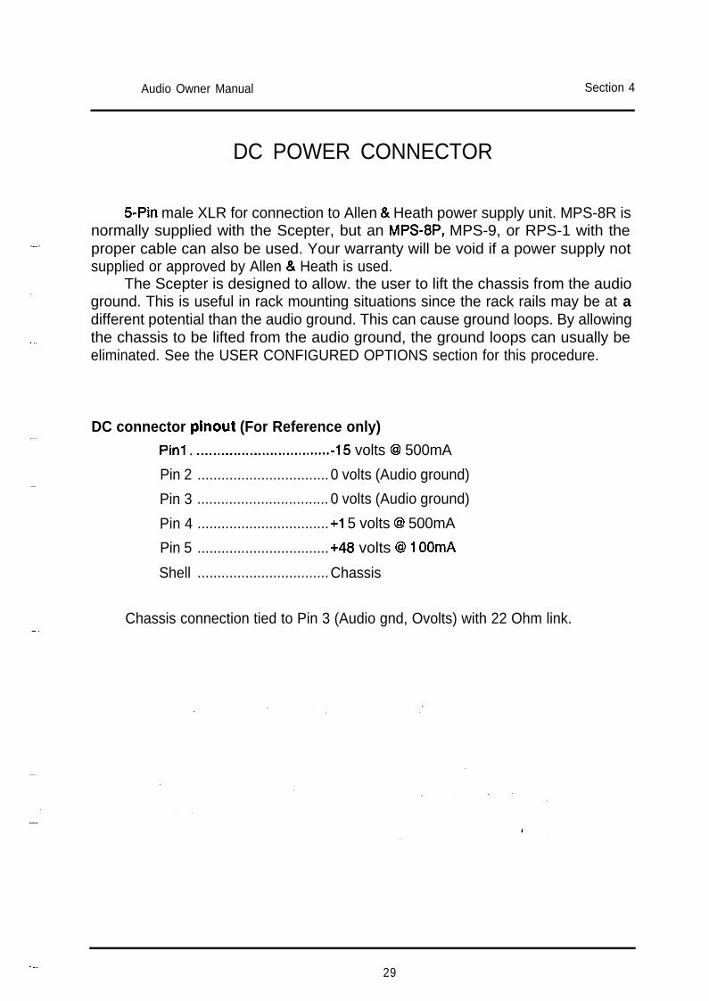
5Pin male XLR for connection to Allen & Heath power supply unit. MPS-8R isnormally supplied with the Scepter, but an MPS-8P, MPS-9, or RPS-1 with theproper cable can also be used. Your warranty will be void if a power supply notsupplied or approved by Allen & Heath is used.
The Scepter is designed to allow. the user to lift the chassis from the audioground. This is useful in rack mounting situations since the rack rails may be at adifferent potential than the audio ground. This can cause ground loops. By allowingthe chassis to be lifted from the audio ground, the ground loops can usually beeliminated. See the USER CONFIGURED OPTIONS section for this procedure.
DC connector pinout (For Reference only)-
Pin1 . **..,.......*..*....*.........*.. -15 volts @ 500mA
Pin 2 .................................0 volts (Audio ground)
Pin 3 ................................. 0 volts (Audio ground)
Pin 4 .................................+I 5 volts @ 500mA
Pin 5 .................................+48 volts @ 1 OOmA
Shell .................................Chassis
Chassis connection tied to Pin 3 (Audio gnd, Ovolts) with 22 Ohm link.
-29
Audio Owner Manual Section 5
SERVICE ACCESS
ACCESS TO MIXER CIRCUITSTo implement any User Options, you will need to gain access to the internal
circuit cards, The various jumper links later defined are located on those cards.Follow the outlined procedure to safely open the Scepter mixer.
The Scepter is composed of individual glass-epoxy circuit cards secured to asilk-screened aluminum front panel. A steel rear panel is secured to the rear of thecircuit cards by numerous jack nuts. This sub-assembly (i.e. Front panel, Circuitcards and Rear Panel) is then inserted into a steel chassis. Eight 6x32 front panelcounter-sunk screws and eight 6x32 rear panel screws hold both assembliestogether. The front carrying handles also hold the two assemblies together with four10x32 screws.
In order to get to the jumper links, you will have to first remove the Frontpanel/Circuit card/Rear panel sub-assembly from the chassis and then remove theRear panel from the Circuit cards. The jumper links will then be accessible. NOTE:If you need to change only the Master options (Mono or Stereo Out Jumpers) thenthe Rear panel DOES NOT have to be separated from the Circuit cards. Eliminatestep 2 and proceed as far as step 7.
DISASSEMBLY
Perform all work on a soft surface to prevent undue scratching of theScepter unit.
Place the Scepter face down (resting on its handles) on a soft surfaceLoosen (do not remove yet) the black plastic nuts from the l/4” jacks.Remove the 8 panel screws securing the Rear panel to the chassis.Turn the Scepter over and remove the 8 countersunk screws securing theFront panel to the Chassis. At this point the Handles screws are the onlyfasteners holding the Front panel Assembly to the Chassis.Support the Scepter on its front, but without using the handles for support. Usea foam block or similar item 2” or greater in height to clear the handles.Remove the 4 countersunk handle screws. Hold onto the handles whenperforming this step to prevent them from rotating and possibly scratching theFront panel.Lift the Chassis off the Front panel assembly.At this point you may make changes to the Master jumper links. The remainingsteps should only be performed if you need to remove the Rear panel. (This isnecessary if Input or L/R jumper links have to be changed or if servicing needs
30
Audio Owner Manual Section 5
to be carried out.- a Free the DC power XLR-5 pin insert from its metal shell by using a small
screwdriver to loosen the XLR setscrew (anti-clockwise). The insert can then-
-
be pulled out the back of the XLR shell. The DC wires to the Master card willremain attached to the insert.
9 Remove the loosened plastic nuts from the l/4” jacks.10 Remove the 2 fixing screws from each XLR jack.11 Lift the Rear panel off the circuit cards.
--
The Circuit cards are now accessible for changes to the jumper links or repairwork. If the main IDC 20 way ribbon harness is removed for service, use care whenit is replaced. Make sure that all pins on all Circuit cards are correctly inserted intothe IDC sockets; it is easy to bend a pin or mistakenly shift over one pin whenputting a socket on. When re-assembling the Scepter, follow the above steps inreverse order.
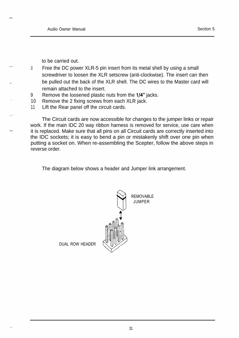
The diagram below shows a header and Jumper link arrangement.
REMOVABLEJUMPER
DUAL ROW HEADER
- 31
Audio Owner Manual Section 5
USER CONFIGURED OPTIONS
There are a number of User options available on the Scepter mixer. They areimplemented with removable jumper links that the user can move to differentcombinations of header pins; no soldering is necessary. (except for the left and rightStereo Return options).
To alter any of the User Configured Options you will have to gain access tothe internal circuit cards. Please read the ACCESS TO MIXER CIRCUITSprocedure in the SERVICE ACCESS section.
OPTION DESCRIPTIONS
Input Channel OptionsSeven different options are available on each Input channel:
Direct OutAux send source selectPre-EQ source selectPre-EQ mute select
1 of 3 choices1 of 3 choices for each Aux1 of 3 choices1 of 2 choices
Direct OutThree choices are available for the Channel Direct Out. Normally the Direct
Out is set to follow the Fader and Mute switch, however there may be situationswhen you may want the Direct Out to stay active even if the Channel is muted. Thiswould allow you to use each input as an independent preamp. If the channel ismuted, the signal would appear only at the Direct Out jack; the Aux sends and L/Rpan feed would be cut.
1 Post-Fader/Post-Mute The Direct Out follows the Channel fader and Muteswitch. This option is factory set.
2 Post-Fader/Pre-Mute The Direct Out follows the Channel fader but theMute switch has no effect on the signal.
3 Pre-Fader/Pre-Mute Neither the fader nor Mute switch affect the Directout.
32
Audio Owner Manual Section 5
-
-
Channel Aux Send Source SelectThree choices are available for each of the four Auxiliary Sends. Aux A & B
are set up as Monitor or Cue sends (Pre-EQ/Pre-Fader); Aux C & D are set as EFXsends (Post-Fader). Normally all Aux sends are muted along with the channel, butthe Pre-EQ source can be set to ignore the Mute switch. (see Pre-Eq Mute/No mutesection) The Pre-EQ can also be set to 1 of 3 different configurations (See Pre-EQSource Select).
-.-1 Pre-EQ Aux Send signal follows Gain control only. Auxes A
& B default factory setting. This source has 3 extraconfiguration options. (see Pre-Eq Source Select)
2 Pre-Fader Aux Send follows the EQ and Mute switches; Faderlevel has no effect. Same signal as PFL.
3 Post-Fader Aux Send follows Fader and Mute Switch. Used forEffect send. Auxes C & D default factory setting.
Pre-EQ Source SelectThree choices are provided for the Pre-EQ source. Normally the Post-Insert/
Post-HPF option is selected. The aux signal will be after any signal processingequipment you may have patched into the Channel Insert jack and also the channelHigh pass filtering. If you want the Aux send to be unaffected by the externalequipment, select the Pre-Insert option. Likewise, choose the Post-lnsert/Pre-HPFpoint if you want the Aux to have the effect but not have the High Pass Filtering.
1 Pre-Insert Pre-EQ point is directly after the channel preampsection. Any external equipment will not affect theaux send signal.
2 Post Insert/Pre-HPF Pre-EQ point follows any external equipment but isnot affected by HPF switch.
3 Post Insert/Post HPF Pre-EQ signal is after any external processingequipment and is affected by the HPF switch. Thisis the factory default setting.
- 33
Audio Owner Manual Section 5
PreEQ Mute/No MuteThe Pre-EQ source (1 of 3 selected above) can be set to follow the Channel
Mute switch or to ignore it. It is normally set to follow the mute. If you desire thesource to be active even when the channel is muted, configure the No Mute option.
1 Pre-EQ Mute Pre-EQ source will mute with the Channel. This isthe factory default setting.
2 Pre-EQ No Mute Pre-EQ source will remain on even when thechannel is muted.
Left and Right Stereo Return OptionsThere are four 10k Ohm resistors (brown,black,orange) that can be set on
each L/R card. These four resistors are located behind the two Aux controls. Theyselect the source for the two Aux sends on each Stereo return. You have manyvariations, for each of the two Aux send sources.
If you select both a Left and Right source, the Aux will be a mono mix of theStereo return.
1 L-R return Pre-level Aux sends A & B configured to follow the pre-levelmono mix of left and right return. This is the factorydefault setting.
2 L-R return Post level Aux sends A & B configured to follow after the postlevel mono mix of left and right return.
If you want to change to Aux A Left only and Aux B Right only, remove theappropriate resistors. You may then configure the resistors for pre or post level foreach aux send.
3 Left return Pre-level Aux sends A and/or B can be configured to followthe left return only.
4 Left return Post-Level Aux sends A and/or B can be configured to followjust the left return after the level control and muteswitch.
5 Right return Pre-level Aux sends A and/or B can be configured to followthe right return only.
6 Right return Post-level Aux sends A and/or B can be configured to followjust the right return after the level control and muteswitch.
34
Audio Owner Manual Section 5
Master OptionsThe user can choose the sources for both the Balanced MONO out XLR
connector and the STEREO OUT l/4” jack socket. These outputs are derived fromsome point in the main Left and Right audio path. The options are: Pre-Insert, Post-Insert/Pre-Fader and Post-Fader.
Normally both the Mono and Stereo outputs are set for Pre-Insert. This makesthem independent of the main L & R faders and any processing equipment that ispatched into the Left or Right Insert jacks.
1 Mono Out Pre-Insert Output is a mono mix of the main left & rightpre-insert signal. This is the factory default setting.
2 Stereo Out Pre-Insert Output is the main left & right pre-insert signal. Tipis left and Ring is right. This is the factory defaultsetting.
Configure the jumper links for Post Insert if you want the MONO and STEREOOUT signals to be affected by any external processing equipment patched into theL & R Inserts.
3 Mono Out Post Insert Output is a mono mix of the main left & right postinsert signal. The L & R fader levels have no effect.
4 Stereo Out Post Insert Output is the main left & right post insert signal. Tipis left and Ring is right. The L & R fader levels haveno effect.
Configure the jumper links for Post-Fader to have both outputs follow the mainL & R outputs.
5 Mono Out Post Fader Output is a mono mix of the main left & right postfader signal. Equivalent to a mono mix direct out.
6 Stereo Out Post Fader Output is the main left & right post fader signal. Tipis left and Ring is right. Equivalent to a stereo directout.
The Mono Output header mixes the two selected sources together. The StereoOut header routes the left source to the left out and the right source to the right out.
Two extra positions are available on the Stereo out header. These points are
Audio Owner Manual Section 5
brought out to holes in the circuit board allowing you to feed an Aux output or othersignal to the Stereo Out. Solder a wire between the hole pad and the desired signalpoint and move the header to the Ext position.
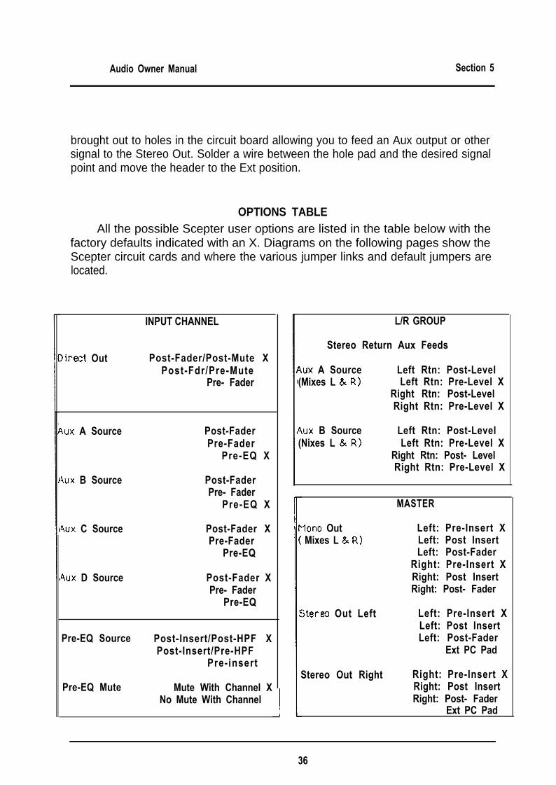
OPTIONS TABLEAll the possible Scepter user options are listed in the table below with the
factory defaults indicated with an X. Diagrams on the following pages show theScepter circuit cards and where the various jumper links and default jumpers arelocated.
INPUT CHANNEL
Iirect Out Post-Fader/Post-Mute XPost-Fdr/Pre-Mute
Pre- Fader
4ux A Source Post-FaderPre-Fader
Pre-EQ X
4ux B Source Post-FaderPre- Fader
Pre-EQ X
4ux C Source Post-Fader XPre-Fader
Pre-EQ
4ux D Source Post-Fader XPre- Fader
Pre-EQ
Pre-EQ Source Post-Insert/Post-HPF XPost-Insert/Pre-HPF
Pre-insert
Pre-EQ Mute Mute With Channel XI No Mute With Channel
L/R GROUP
Stereo Return Aux Feeds
4ux A Source(Mixes L & R)
Left Rtn: Post-LevelLeft Rtn: Pre-Level X
Right Rtn: Post-LevelRight Rtn: Pre-Level X
4ux B Source(Nixes L & R)
Left Rtn: Post-LevelLeft Rtn: Pre-Level X
Right Rtn: Post- LevelRight Rtn: Pre-Level X
MASTER
Ion0 OutMixes L & R)
Left: Pre-Insert XLeft: Post InsertLeft: Post-Fader
Right: Pre-Insert XRight: Post InsertRight: Post- Fader
stereo Out Left Left: Pre-Insert XLeft: Post InsertLeft: Post-Fader
Ext PC Pad
Stereo Out Right Right: Pre-Insert XRight: Post InsertRight: Post- Fader
Ext PC Pad
36

-Audio Owner Manual Section 5
CHASSIS GROUND LIFT
-
-
Normally the chassis of the Scepter is connected to the audio ground with alink on the DC Input connector.
The chassis can be lifted from the audio ground by removing this link.
This should not be confused with disconnecting the ground on an AC plug.The AC ground is a safety ground; it is there as protection from electrocution ifsome component should fail and cause an exposed surface to become live. Thesafety ground is designed to shunt this voltage to ground, causing the equipment oroutlet fuse to blow. The Power supply chassis is attached to this AC ground sincethere are potentially hazardous voltages inside the case. The Scepter chassis andaudio ground are isolated from this AC ground since the Power Supply feeds onlylow-voltage DC to the mixer. The Scepter chassis and audio ground are floating inrespect to the AC ground; they will obtain their ground from the external equipmentthey are attached to.
In most rack situations, there are a number of grounds tied together via themetal rack rails. This can lead to ground loops which may cause hum in a system.These ground loops can be eliminated in many casesby isolating the equipmentaudio ground from this metal rail. If you need to isolate the Scepter chassis thenfollow the procedure outlined below:
The Scepter is also provided with Pin-l lifts on all its Balanced outputs. Insome cases lifting Pin 1 is all that is required to fix a ground loop problem.
Chassis-Audio Ground isolation procedure:1 Release the DC Power connector from the rear panel by removing the 2 fixing
screws2 Carefully ease the connector out and locate the chassis lug (see diagram)3 Locate the bare wire link that is attached to this lug(see diagram)4 Cut this wire and dress it to prevent shorting.5 Re-install the connector and screws.
REMOVE THESE 2SCREWS TO FREEDC POWER JACK
FROM REARPANEL
REAR PANEL
DC POWER WIRES
UT THIS BARE WlRfFROM THE SOLDER
DC POWER INPUT5-PIN XLR
LUG TO ISOLATE THfCHASSIS FROM THE
AUDIO GROUND
- 37