Embed Size (px)
Citation preview
* Corresponding author: M. Klach, E-mail: [email protected] 1
Laboratory of Electronics and Information Technologies, University of Sfax, ENIS, BP W, 3038 Sfax, Tunisia 2
Laboratoire Systèmes et Applications des Technologies de l’Information et de l’Energie, Ecole Normale
Supérieure de Cachan, Avenue du Président Wilson, 94235 Cachan, France
Copyright © JES 2016 on-line : journal/esrgroups.org/jes
M. Klach1,*
,
H. Aloui1,
R. Neji1,
M. Gabsi2,
M. Lecrivain2
J. Electrical Systems 12-1 (2016): 133-145
Regular paper
Hybridization effect on generation
capability of an embedded CPA
JES
Journal of Journal of Journal of Journal of Electrical Electrical Electrical Electrical SystemsSystemsSystemsSystems
The purpose of this paper is to compare performances of two configurations of an embedded Claw Pole Alternator (CPA) where the excitation winding is transferred to the stator side. These configurations are: the Simple Excited Automotive Alternator (SE2A) and the Hybrid Excited Automotive Alternator (HE2A). Performed study is based on test at no-load and under load operation regimes, using Magnetic Equivalent Circuit (MEC) models validated experimentally. It has been found that the hybrid Excited claw pole alternator provides higher performances, due to the increase of leakage flux through the integration of permanent magnets between adjacent rotor claws.
Keywords: automotive alternator; magnetic equivalent circuit; flux paths; simple excitation;
hybridization; experimental tests.
Article history: Received 15 December 2015, Accepted 5 February 2016
1. Introduction
During the last years, the modeling of new claw pole topologies aimed to automotive
alternators has been focused in several works [1], [2], [3]. The popularity of such type of
electrical machines emanates from the exploitation in automotive industry. Indeed, the
hetero-polar topology of its rotor makes possible the integration of a high pole pair number
in a reduced volume leading so to an interesting generation capabilities [4]. Nevertheless,
despite their low manufacturing cost, conventional alternators suffer from both servicing
costs and reduced efficiency. For that, the improvement of such a machine through the
integration of new components as permanent magnets or the proposition of new topologies
represents a fertile research domain [5],[6]. It is the case the present paper where two
modified topologies of an automotive claw pole alternator are compared using magnetic
equivalent circuit model validated experimentally. Mentioned modifications concern the
field winding, which is transferred to the stator side rather than rotor side as in conventional
alternator, and the insertion of new components to permit flux flowing. Obtained
configuration is named the Simple Excited Automotive Alternator (SE2A). Furthermore,
through the integration of permanent magnets between adjacent rotor claws of the SE2A, a
second configuration is named the Hybrid Excited Automotive Alternator (HE2A).
This paper encloses three major parts. The first part is aimed to the description the SE2A
composition and principal of operation. Then, results carried out using the MEC of such
structure are validated experimentally. Finally, the effect of the hybridization of the
alternator excitation is studied.
M. Klach et al: Hybridization effect on generation capability of an embedded CPA
134
2. Structure Presentation
The SE2A concept presents a claw pole topology where the inductor winding is placed in
the stator side rather than in rotor. It is equipped with a three-phase armature winding and
encloses twelve claws leading to a six pole pair structure. The stator magnetic circuit is made
up of two parts. The first one is the usual laminated cylinder composed of iron sheets and
devoted for the insertion of alternator armature. In addition, the second part is a massive
cylinder surrounding laminated part, committed to inductor flux’s flowing and called “stator
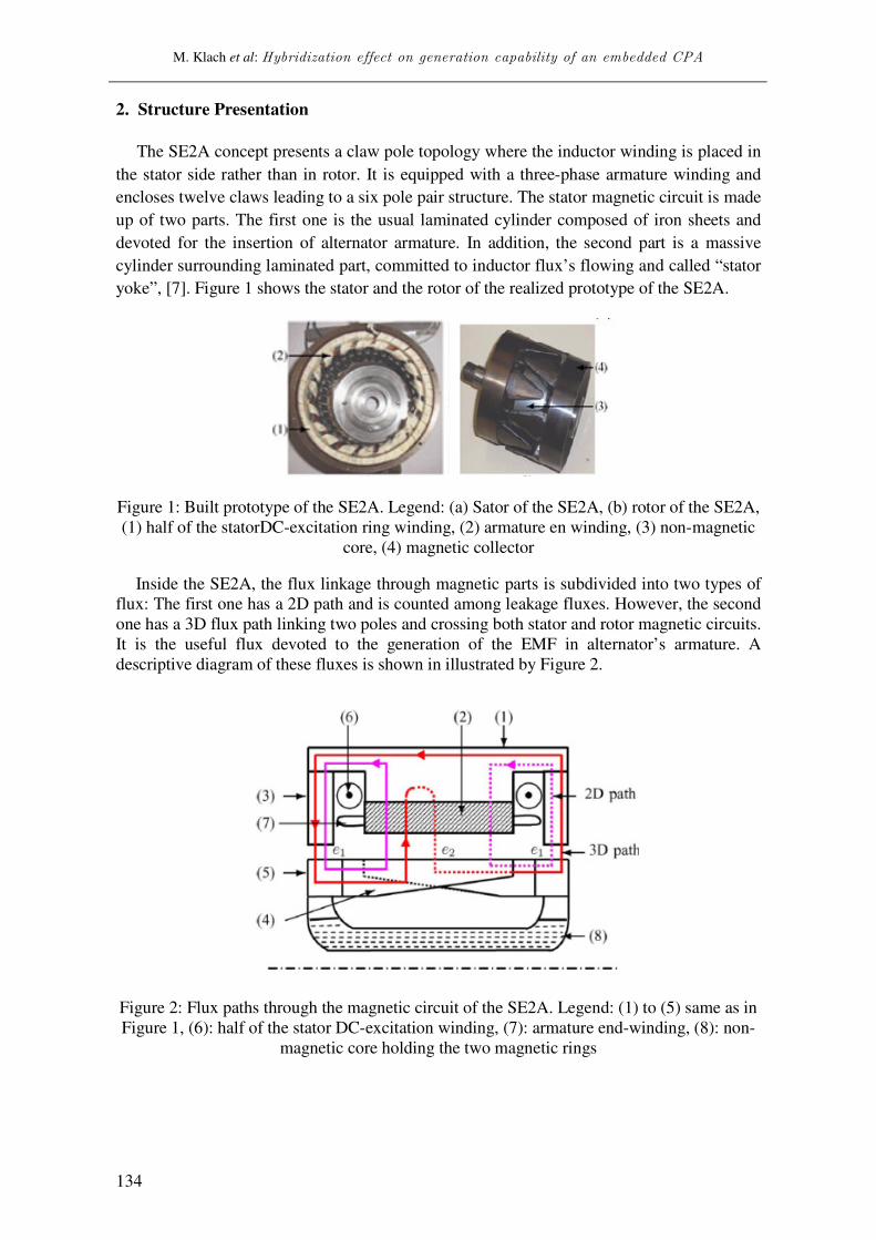
yoke”, [7]. Figure 1 shows the stator and the rotor of the realized prototype of the SE2A.
Figure 1: Built prototype of the SE2A. Legend: (a) Sator of the SE2A, (b) rotor of the SE2A,
(1) half of the statorDC-excitation ring winding, (2) armature en winding, (3) non-magnetic
core, (4) magnetic collector
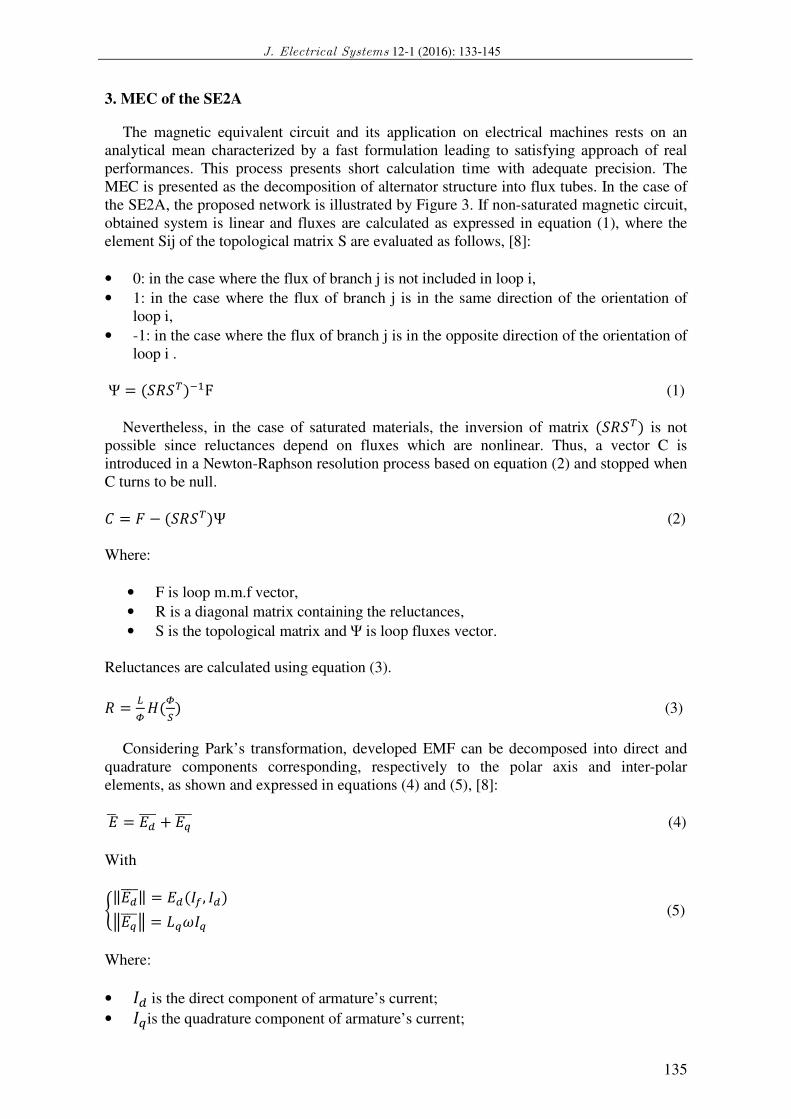
Inside the SE2A, the flux linkage through magnetic parts is subdivided into two types of
flux: The first one has a 2D path and is counted among leakage fluxes. However, the second
one has a 3D flux path linking two poles and crossing both stator and rotor magnetic circuits.
It is the useful flux devoted to the generation of the EMF in alternator’s armature. A
descriptive diagram of these fluxes is shown in illustrated by Figure 2.
Figure 2: Flux paths through the magnetic circuit of the SE2A. Legend: (1) to (5) same as in
Figure 1, (6): half of the stator DC-excitation winding, (7): armature end-winding, (8): non-
magnetic core holding the two magnetic rings
J. Electrical Systems 12-1 (2016): 133-145
135
3. MEC of the SE2A
The magnetic equivalent circuit and its application on electrical machines rests on an
analytical mean characterized by a fast formulation leading to satisfying approach of real
performances. This process presents short calculation time with adequate precision. The
MEC is presented as the decomposition of alternator structure into flux tubes. In the case of
the SE2A, the proposed network is illustrated by Figure 3. If non-saturated magnetic circuit,
obtained system is linear and fluxes are calculated as expressed in equation (1), where the
element Sij of the topological matrix S are evaluated as follows, [8]:
• 0: in the case where the flux of branch j is not included in loop i,
• 1: in the case where the flux of branch j is in the same direction of the orientation of
loop i,
• -1: in the case where the flux of branch j is in the opposite direction of the orientation of
loop i .
Ψ = (����)��F (1)
Nevertheless, in the case of saturated materials, the inversion of matrix (����) is not
possible since reluctances depend on fluxes which are nonlinear. Thus, a vector C is
introduced in a Newton-Raphson resolution process based on equation (2) and stopped when
C turns to be null.
= � − (����)Ψ (2)
Where:
• F is loop m.m.f vector,
• R is a diagonal matrix containing the reluctances,
• S is the topological matrix and Ψ is loop fluxes vector.
Reluctances are calculated using equation (3).
� = �� �(�� ) (3)
Considering Park’s transformation, developed EMF can be decomposed into direct and
quadrature components corresponding, respectively to the polar axis and inter-polar
elements, as shown and expressed in equations (4) and (5), [8]:
�� = ����� + ����� (4)
With
���������� = ��(��, ��)��������� = �!�� � (5)
Where:
• �� is the direct component of armature’s current;
• ��is the quadrature component of armature’s current;
M. Klach et al: Hybridization effect on generation capability of an embedded CPA
136
• ��is alternator’s field current.
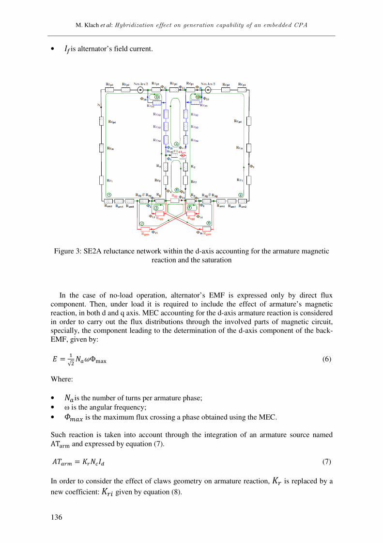
Figure 3: SE2A reluctance network within the d-axis accounting for the armature magnetic
reaction and the saturation
In the case of no-load operation, alternator’s EMF is expressed only by direct flux
component. Then, under load it is required to include the effect of armature’s magnetic
reaction, in both d and q axis. MEC accounting for the d-axis armature reaction is considered
in order to carry out the flux distributions through the involved parts of magnetic circuit,
specially, the component leading to the determination of the d-axis component of the back-
EMF, given by:
� = �√# $%!Φ&'( (6)
Where:
• $% is the number of turns per armature phase;
• ω is the angular frequency;
• )*%+ is the maximum flux crossing a phase obtained using the MEC.
Such reaction is taken into account through the integration of an armature source named AT'.& and expressed by equation (7).
/0%1* = 21$3�� (7)
In order to consider the effect of claws geometry on armature reaction, 21 is replaced by a
new coefficient: 214 given by equation (8).
J. Electrical Systems 12-1 (2016): 133-145
137
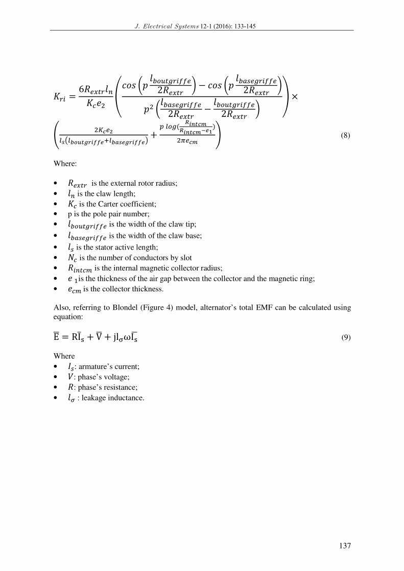
214 = 6�6+718923:# ;<=> ?@ 8ABC7D14��62�6+71 F − <=> ?@ 8A%G6D14��62�6+71 F@# ?8A%G6D14��62�6+71 − 8ABC7D14��62�6+71 F H ×
J #KL6MNOPNQRSTUVWXXYZNQ[OYUVWXXY\ + ] NBD( ^W_TL`^W_TL`aYb)#c6L` d (8)
Where:
• �6+71 is the external rotor radius;
• 89 is the claw length;
• 23 is the Carter coefficient;
• p is the pole pair number;
• 8ABC7D14��6 is the width of the claw tip;
• 8A%G6D14��6 is the width of the claw base;
• 8G is the stator active length;
• $3 is the number of conductors by slot
• �4973* is the internal magnetic collector radius;
• : �is the thickness of the air gap between the collector and the magnetic ring;
• :3* is the collector thickness.
Also, referring to Blondel (Figure 4) model, alternator’s total EMF can be calculated using
equation:
E� = RIhi + V� + jlmωIi� (9)
Where
• �G: armature’s current;
• o: phase’s voltage;
• �: phase’s resistance;
• 8p : leakage inductance.
M. Klach et al: Hybridization effect on generation capability of an embedded CPA
138
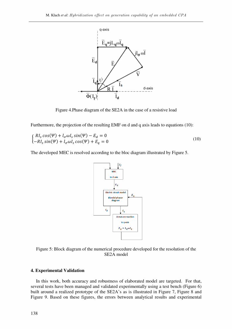
Figure 4.Phase diagram of the SE2A in the case of a resistive load
Furthermore, the projection of the resulting EMF on d and q axis leads to equations (10):
q ��G <=>(r) + 8p!�G >st(r) − �� = 0−��G >st(r) + 8p!�G <=>(r) + �� = 0� (10)
The developed MEC is resolved according to the bloc diagram illustrated by Figure 5.
Figure 5: Block diagram of the numerical procedure developed for the resolution of the
SE2A model
4. Experimental Validation
In this work, both accuracy and robustness of elaborated model are targeted. For that,
several tests have been managed and validated experimentally using a test bench (Figure 6)
built around a realized prototype of the SE2A’s as is illustrated in Figure 7, Figure 8 and
Figure 9. Based on these figures, the errors between analytical results and experimental

J. Electrical Systems 12-1 (2016): 133-145
139
records are calculated and summarized in Table I. We can clearly notice the good
agreement between the SE2A MEC values and experimental points with a maximum error
not exceeding 7%, except starting point.
Figure 6: Experimental test bench of the SE2A
Figure 7: SE2A’s EMF Vs field current under no-load operation regime, for a speed of
1000 rpm. Legend: solid line: MEC results, stars: experimental results
Figure 8. Armature short-circuited current versus the field current, for a speed of 1000 rpm.
Legend: solid line: MEC results, stars: Experimental results
0 2 4 6 80
10
20
30
40
50
60
70
field current (A)
Ba
ck-E
MF
(V
)
0 1 2 3 40
0.5
1
1.5
2
2.5
3
3.5
field current (A)
Arm
atu
re s
ho
rt-c
irc
uit
ed
cu
rre
nt
(A)

M. Klach et al: Hybridization effect on generation capability of an embedded CPA
140
Figure 9: Armature voltage versus armature current in the case of resistive load for a field
current of 4A at 1000 rpm, Legend: solid line: MEC results, stars: experimental results
Table 1:Gap between analytical results and experimental ones
No-load operation
regime Short-circuited armature regime
Under resistive load
regime
Iv(A) Error (%) Iw(A) Error (%) Ix(A) Error (%))
1 5 1 17 0.25 2.6
2 0.4 1.5 4.6 0.4 0.4
3 1.8 2 5.7 0.6 0.7
4 6.6 2.5 7.2 0.95 3.5
5 1.4 3 2 1.15 2.7
6 2.3 3.5 0.6 1.66 1.8
5. MEC of the HE2A
Two excitation sources are enclosed in the present structure. Besides the classical field
winding, Barium ferrites permanent magnets are inserted in-between rotor adjacent claws in
order to counter flux leakage in this part of the alternator, as shown in Figure 10, [9],[10].
Table 2 gives the characteristics of used ferrite PMs.
J. Electrical Systems 12-1 (2016): 133-145
141
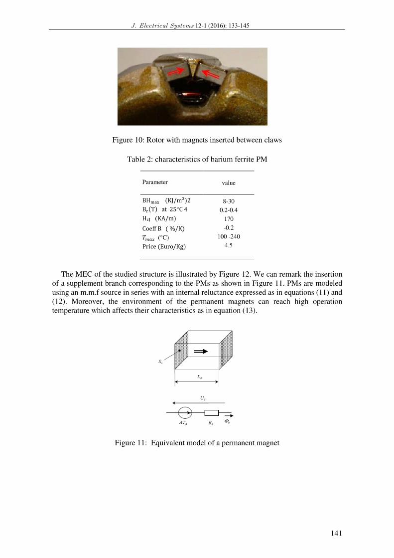
Figure 10: Rotor with magnets inserted between claws
Table 2: characteristics of barium ferrite PM
Parameter value
BH&'( (KJ/m�)2 B.(T) at 25°C 4 H�� (KA/m) Coeff B ( %/K) 0*%+ (°C) Price (Euro/Kg)
8-30
0.2-0.4
170
-0.2
100 -240
4.5
The MEC of the studied structure is illustrated by Figure 12. We can remark the insertion
of a supplement branch corresponding to the PMs as shown in Figure 11. PMs are modeled
using an m.m.f source in series with an internal reluctance expressed as in equations (11) and
(12). Moreover, the environment of the permanent magnets can reach high operation
temperature which affects their characteristics as in equation (13).
Figure 11: Equivalent model of a permanent magnet

M. Klach et al: Hybridization effect on generation capability of an embedded CPA
142
Figure 12: HE2A reluctance network within the d-axis accounting for the armature magnetic
reaction and the saturation
/0%� = �V�[���V[ (11)
�% = �[���V[�[ (12)
/0%(0) = �VM��[���V[ 27(0) (13)
Where:
• �1 is the magnet polarization
• �1#� is the remanent polarization of the permanent magnet at 25 ° C.
• �% is the section area.
• %is the flux path average length
• μ� is air permeability
• μ1% is the relative permeability
• 27(0) = 1 − 0.002(0 − 25), T in °C: reflects the temperature’s effect on the PM
polarization.
6. Hybridization effect on alternator capabilities
The present section is aimed to a comparison study based on utilization of established
MECs of both configurations of the modified automotive alternator (SE2A and HE2A) in
order to demonstrate the effect of PMs integration on generation capabilities.
To extract alternator performances under load regime at desired operation point, the back
EMF is deduced from no-load regime test (Figure 13) and the machine reactance is deduced
J. Electrical Systems 12-1 (2016): 133-145
143
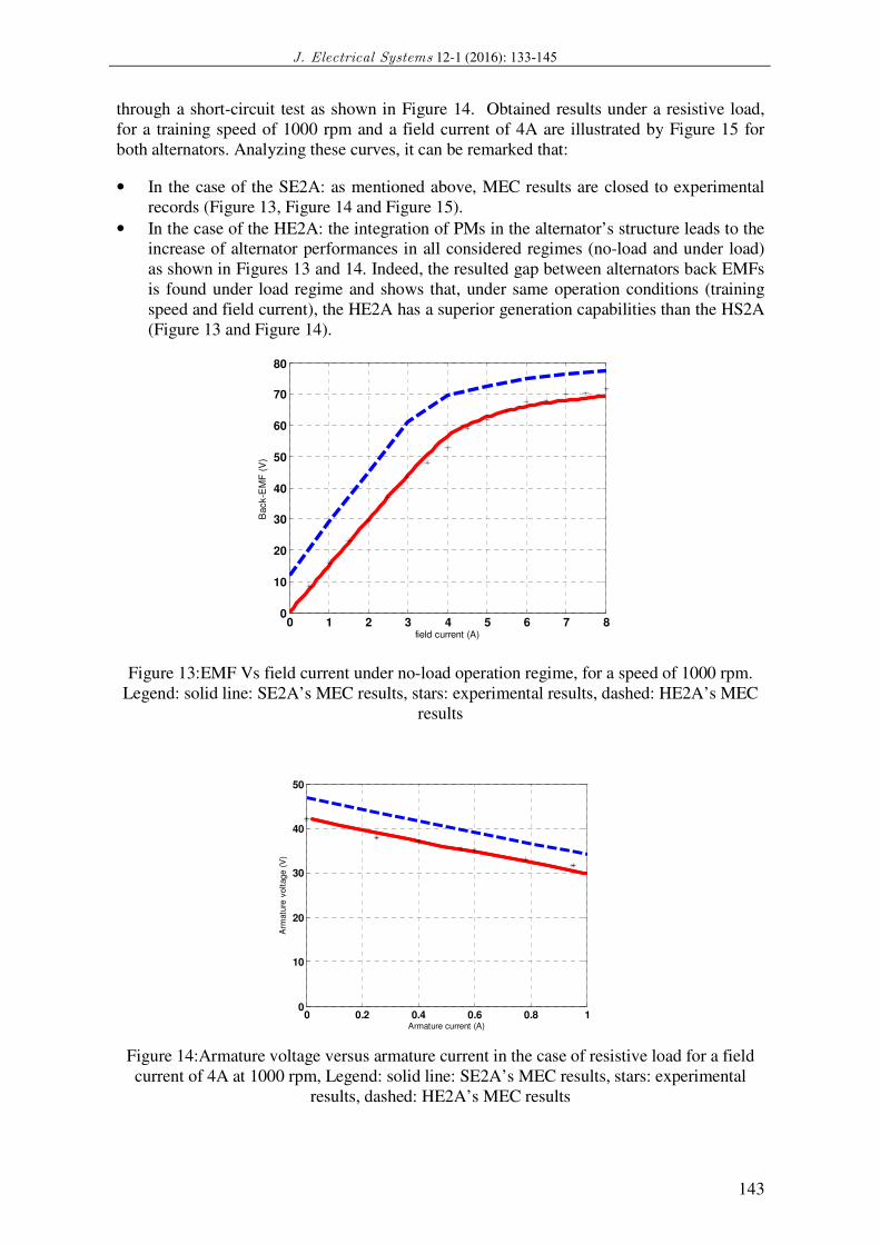
through a short-circuit test as shown in Figure 14. Obtained results under a resistive load,
for a training speed of 1000 rpm and a field current of 4A are illustrated by Figure 15 for
both alternators. Analyzing these curves, it can be remarked that:
• In the case of the SE2A: as mentioned above, MEC results are closed to experimental
records (Figure 13, Figure 14 and Figure 15).
• In the case of the HE2A: the integration of PMs in the alternator’s structure leads to the
increase of alternator performances in all considered regimes (no-load and under load)
as shown in Figures 13 and 14. Indeed, the resulted gap between alternators back EMFs
is found under load regime and shows that, under same operation conditions (training
speed and field current), the HE2A has a superior generation capabilities than the HS2A
(Figure 13 and Figure 14).
Figure 13:EMF Vs field current under no-load operation regime, for a speed of 1000 rpm.
Legend: solid line: SE2A’s MEC results, stars: experimental results, dashed: HE2A’s MEC
results
Figure 14:Armature voltage versus armature current in the case of resistive load for a field
current of 4A at 1000 rpm, Legend: solid line: SE2A’s MEC results, stars: experimental
results, dashed: HE2A’s MEC results
0 1 2 3 4 5 6 7 80
10
20
30
40
50
60
70
80
field current (A)
Back-E
MF
(V
)
0 0.2 0.4 0.6 0.8 10
10
20
30
40
50
Armature current (A)
Arm
atu
re v
oltage (
V)

M. Klach et al: Hybridization effect on generation capability of an embedded CPA
144
As a Consequence, we can say that the placement of the permanent magnets in-between
adjacent claws makes the rotor of the HE2A turns to be heavier than the rotor of the SE2A.
Nevertheless, an increase is registered on the power density of the hybrid excited alternator
as shown in Figure 14. To argue these findings, let us evaluate the power density of each
alternator at the operation point corresponding to (Iexc = 4A, N = 1000rpm, and Iload = 1A).
Referring to [11] the masse of the SE2A is equal to 6.5 Kg for that:
� The masse of the HE2S is
MHE2S = MSE2A + 12xMVAxVA = 6.70 Kg (14)
� The power density of the SE2S is
PdSE2S = PSE2A / MSE2A = 13.8W/Kg (15)
� The power density of the HE2S is
PdHE2S = PHE2A / MHE2A =15.34 W/Kg (16)
7. Conclusion
The hetero-polar topology of the rotor in conventional automotive alternators makes
possible to obtain a high pole pair number in a reduced volume. Moreover, these alternators
have a low manufacturing cost, but they are penalized by maintenance costs and reduced
efficiency.
This paper deals with a reluctant network modeling of two modified configurations of
automotive alternator where the field winding is transferred from rotor to stator. Newthon-
Raphson numerical method is used to resolve established models and estimate machine
performance at both no-load and under resistive load regimes. Obtained results in the case of
the simple excited configuration (SE2A) were validated experimentally. Besides, in order to
investigate hybridization effect on the alternator’s generation capabilities, permanent
magnets are introduced between claws poles and reluctant model was exploited to carry out
performances of the HE2A. It has been found that, compared to the SE2A, the power density
of the hybrid excited alternator registered an increase despite a heavier structure due to the
permanent magnets mass.
References [1] M. Hecquet and P. Brochet, Modeling of a claw pole alternator using permeance network coupled with
electric circuits, IEEE Trans. Magn, 31(3), 2131-2134, 1995.
[2] L. Li, A. K. Lebouc, A. Foggia, and J. C. Mipo, Influence of magnetic materials on claw pole machines behavior, IEEE Transactions on Magetics, 46(2), 574-577, 2010.
[3] V. Ostovic, J.M. Miller, V.Garg, and R.D. Schultz, S. Swales, A Magnetic Equivalent Circuit Based Performance Computation of a Lundell Alternator, IEEE Trans. Magn, 35(4), 825 - 830, 1999.
[4] M. Chaib,S. Tounsi, R. Neji, Design and optimization of axial permanent magnet machine for electric
vehicle, Journal of Electrical Systems, 5(1), 2009.
[5] Y. P. Dou, Y. G. Guo, J. G. Zhu, and H. Y. Lu, Effect of armature reaction of a permanent-magnet claw pole
SMC motor, IEEE Trans. Magn, 34( 6), 2561–2563, 2007.
[6] S. H. Lee, S. O. Kwon, J. J. Lee, and J. P. Hong, Characteristic analysis of claw-pole machine using
improved equivalent magnetic circuit, IEEE Trans. Magn, 45(10), 4570-4573, 2009.
[7] H. Aloui, A. Ibala, A. Masmoudi, M. Gabsi and M. Lecrivain, Reluctant network based investigation of a claw pole alternator with dc excitation in the stator, in Inter. Journal for Computation and Mathematics in
Electrical and Electronic Engineering, 27( 5), 1016-1032, 2008.

J. Electrical Systems 12-1 (2016): 133-145
145
[8] A.Delale, L.Albert, L.Gerbaud, and F.Wurtz , Automatic Generation of Sizing Models for the Optimization of Electromagnetic Devices Using Reluctance Networks, IEEE Trans .Magn, 40(2), 2004.
[9] Y. Amara et al., Hybrid Excitation Synchronous Machines: Energy-Efficient Solution for Vehicles Propulsion, IEEE Trans on Vehicular.Techn, 58(5), 2137 - 2149, 2009.
[10] D. Hagstedt, F. Marquez, and M. Alakula, A comparison between PMSM, EMSM and SMSM in a BAS application, in XVIII Int. Conf. Electrical Machines, Vilamoura, Portugal, 1(4): 2034-2038, 2008.
[11] H. Aloui, Machine Synchrone à Simple et à Double Excitation : Application aux Generateurs Embarques, PhD Dissertation, Sfax Engineering School, Sfax, Tunisia, 2008.