Embed Size (px)
Citation preview
IRI-TR-10-05
Slave architecture for the Robonova MR-C3024using the HMI protocol
IRI Technical Report
codename Hydrozoa
Edgar Simo SerraJordi Pegueroles Queralt
Abstract
The goal of the project is to develop a new firmware for the servo control board Hitec MR-C3024 [8] to improve its specifications. This board will be used to control the movement of ahumanoid robot, driven by digital servos using the communications protocol HMI, developedby Hitech.
Institut de Robotica i Informatica Industrial (IRI)Consejo Superior de Investigaciones Cientıficas (CSIC)
Universitat Politecnica de Catalunya (UPC)Llorens i Artigas 4-6, 08028, Barcelona, Spain
Tel (fax): +34 93 401 5750 (5751)
http://www.iri.upc.edu
Corresponding author:
E. Simotel: +34 93 405 [email protected]
http://www.iri.upc.edu/staff/esimo
Copyright IRI, 2010
CONTENTS 1
Contents
1 Introduction 3
2 Hardware Design 42.1 HMI interface . . . . . . . . . . . . . . . . . . . . . . . . . . . . . . . . . . . . . . 42.2 Expansion Board . . . . . . . . . . . . . . . . . . . . . . . . . . . . . . . . . . . . 5
3 Software design 73.1 Software layout . . . . . . . . . . . . . . . . . . . . . . . . . . . . . . . . . . . . . 73.2 Communication subsystem . . . . . . . . . . . . . . . . . . . . . . . . . . . . . . . 73.3 Servo subsystem . . . . . . . . . . . . . . . . . . . . . . . . . . . . . . . . . . . . 93.4 Group subsystem . . . . . . . . . . . . . . . . . . . . . . . . . . . . . . . . . . . . 93.5 Scheduler subsystem . . . . . . . . . . . . . . . . . . . . . . . . . . . . . . . . . . 103.6 Host High level API . . . . . . . . . . . . . . . . . . . . . . . . . . . . . . . . . . 113.7 Unit Tests . . . . . . . . . . . . . . . . . . . . . . . . . . . . . . . . . . . . . . . . 11
4 Testing 124.1 Getting Started . . . . . . . . . . . . . . . . . . . . . . . . . . . . . . . . . . . . . 124.2 Calibration . . . . . . . . . . . . . . . . . . . . . . . . . . . . . . . . . . . . . . . 124.3 Experimental Setup . . . . . . . . . . . . . . . . . . . . . . . . . . . . . . . . . . 134.4 Results . . . . . . . . . . . . . . . . . . . . . . . . . . . . . . . . . . . . . . . . . . 13
5 Conclusions and Future Work 15
Bibliography 16
A Using the CRobot Library 17
B MR-C3024 bootloader 18B.1 Why we need a bootloader? . . . . . . . . . . . . . . . . . . . . . . . . . . . . . . 18B.2 Reverse engineering . . . . . . . . . . . . . . . . . . . . . . . . . . . . . . . . . . . 18B.3 Bootloader sequence and algorithm . . . . . . . . . . . . . . . . . . . . . . . . . . 18B.4 Software Usage . . . . . . . . . . . . . . . . . . . . . . . . . . . . . . . . . . . . . 19
C Software Documentation 20C.1 testservo . . . . . . . . . . . . . . . . . . . . . . . . . . . . . . . . . . . . . . . . . 20
C.1.1 Compilation . . . . . . . . . . . . . . . . . . . . . . . . . . . . . . . . . . . 20C.1.2 Usage . . . . . . . . . . . . . . . . . . . . . . . . . . . . . . . . . . . . . . 20C.1.3 Setting the ID . . . . . . . . . . . . . . . . . . . . . . . . . . . . . . . . . 20
C.2 testfirmware . . . . . . . . . . . . . . . . . . . . . . . . . . . . . . . . . . . . . . . 20C.2.1 Compilation . . . . . . . . . . . . . . . . . . . . . . . . . . . . . . . . . . . 21C.2.2 Usage . . . . . . . . . . . . . . . . . . . . . . . . . . . . . . . . . . . . . . 21
C.3 calcspeed . . . . . . . . . . . . . . . . . . . . . . . . . . . . . . . . . . . . . . . . 21C.3.1 Compilation . . . . . . . . . . . . . . . . . . . . . . . . . . . . . . . . . . . 21C.3.2 Usage . . . . . . . . . . . . . . . . . . . . . . . . . . . . . . . . . . . . . . 21
C.4 testspeed . . . . . . . . . . . . . . . . . . . . . . . . . . . . . . . . . . . . . . . . 22C.4.1 Compilation . . . . . . . . . . . . . . . . . . . . . . . . . . . . . . . . . . . 22C.4.2 Usage . . . . . . . . . . . . . . . . . . . . . . . . . . . . . . . . . . . . . . 22
C.5 testplot . . . . . . . . . . . . . . . . . . . . . . . . . . . . . . . . . . . . . . . . . 22C.5.1 Compilation . . . . . . . . . . . . . . . . . . . . . . . . . . . . . . . . . . . 22C.5.2 Usage . . . . . . . . . . . . . . . . . . . . . . . . . . . . . . . . . . . . . . 22
2 LIST OF FIGURES
List of Figures
1 Bare HMI interface. . . . . . . . . . . . . . . . . . . . . . . . . . . . . . . . . . . 42 MR-C3024 expansion board schematic with 1 kOhm pullups. . . . . . . . . . . . 53 MR-C3024 expansion board layout . . . . . . . . . . . . . . . . . . . . . . . . . . 64 Robot’s architecture . . . . . . . . . . . . . . . . . . . . . . . . . . . . . . . . . . 65 Overview of interactions between the different software subsystems. . . . . . . . . 86 Overview of group synchronization. . . . . . . . . . . . . . . . . . . . . . . . . . . 107 An approximation of the HSR-8498 servo speed curve . . . . . . . . . . . . . . . 128 An approximation of the HSR-5498 servo speed curve . . . . . . . . . . . . . . . 139 View of the Hydrozoa testing set up . . . . . . . . . . . . . . . . . . . . . . . . . 1310 Close up view of the Hydrozoa testing set up . . . . . . . . . . . . . . . . . . . . 1411 Results of the testplot application . . . . . . . . . . . . . . . . . . . . . . . . . . 14
Section 1 Introduction 3
1 Introduction
For a robot to move well, it must have a highly synchronized software and hardware system.In the case of humanoid robots, this need is even more accentuated, because for the robot toappear and move like a humanoid, it must be very fluid.
The Humanoid Lab Project currently (year 2010) uses a board developed by Hitech in orderto control the motors of the robot. While this board is effective when used as an autonomousboard, it is lacking when used as a slave. When the Humanoid Lab Project added an on-boardcomputer to deal with inverse kinematics and other high level processes major flaws were foundfor this functionality in the slave board. To overcome these problems it was proposed to designa minimal electronics and software system to overcome these problems.
The most important problems with the MR-C3024 [8] lay in the fact that it’s meant to workas a host and not a slave. When tried to use in slave configuration it generally displays reallyslow communication and low reliability. It can not give motor feedback nor stop the motors oncethey have been made to move. This makes it very limited as a slave. As a host it has similarlimitations. It must be programmed in Robobasic [6] which is a generally inflexible languagewith many limitations. This makes things like inverse kinematics nearly impossible to implementon the MR-C3024 [8] and the impossibility to take into account movement dynamics.
The name Hydrozoa comes from the animal which generally consist of many polyps arounda central cavity that are related to jellyfish. If we think of the polyps as servos and the centralcavity as the MR-C3024 [8] it conveys the message of a group of servos working together like aHydrozoa.
The Hydrozoa Projects aims to replace the firmware of the Hitec MR-C3024 board [8] toaugment it’s capability as a slave device. It will make the most of the hardware available andrequire the minimum amount of support electronics for the final implementation. A majorfeature is instead of using the traditional PWM interface of the servos, it uses the HMI interfaceof the HITEC Digital Servos like the HSR-8498 Servo [7]. This allows servo feedback when doinginverse kinematics. This will all be done following the philosophy of open source. The opennessis fundamental since allows other users to learn how it is implemented while at the same timeallow them to solve possible issues and add new features in the future.
This technical document is split into three parts: hardware design [section 2], software design[section 3] and testing [section 4] for easier reading. The section 2 goes into detail of the supportelectronics needed to be able to use the Hydrozoa firmware. The technical details of the softwareimplementation is explained in section 3. The explanation on the entire set up and the resultsof the Hydrozoa firmware are explained in section 4.
4 Slave architecture for the Robonova MR-C3024using the HMI protocolIRI Technical Report
2 Hardware Design
The HMI interface used by digital servios requires a small interface circuit. For this a smallelectronic support board was designed that implements the serial TTL to HMI interface. Thisdesign allows servos to be connected by daisy chaining which also requires more headers toconnect the servos.
2.1 HMI interface
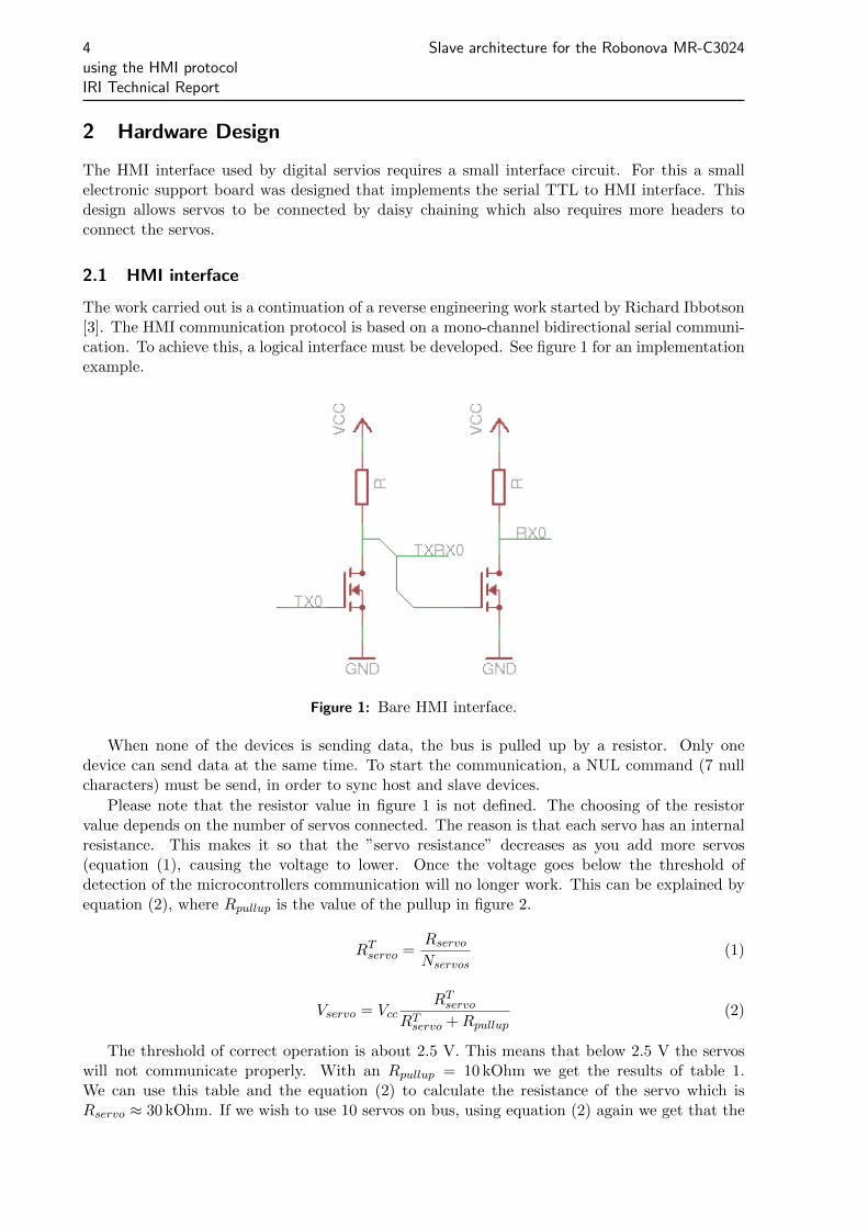
The work carried out is a continuation of a reverse engineering work started by Richard Ibbotson[3]. The HMI communication protocol is based on a mono-channel bidirectional serial communi-cation. To achieve this, a logical interface must be developed. See figure 1 for an implementationexample.
Figure 1: Bare HMI interface.
When none of the devices is sending data, the bus is pulled up by a resistor. Only onedevice can send data at the same time. To start the communication, a NUL command (7 nullcharacters) must be send, in order to sync host and slave devices.
Please note that the resistor value in figure 1 is not defined. The choosing of the resistorvalue depends on the number of servos connected. The reason is that each servo has an internalresistance. This makes it so that the ”servo resistance” decreases as you add more servos(equation (1), causing the voltage to lower. Once the voltage goes below the threshold ofdetection of the microcontrollers communication will no longer work. This can be explained byequation (2), where Rpullup is the value of the pullup in figure 2.
RTservo =
Rservo
Nservos(1)
Vservo = VccRT
servo
RTservo + Rpullup
(2)
The threshold of correct operation is about 2.5 V. This means that below 2.5 V the servoswill not communicate properly. With an Rpullup = 10 kOhm we get the results of table 1.We can use this table and the equation (2) to calculate the resistance of the servo which isRservo ≈ 30 kOhm. If we wish to use 10 servos on bus, using equation (2) again we get that the
Section 2 Hardware Design 5
Table 1: Input voltage to the servos depending on the number of servos connected.Input Voltage Nmuber of servos connected
3.75 V 1
3.00 V 2
2.50 V 3
2.25 V 4
pullup should be Rpullup < 3 kOhm. This value depends on how many servos will be connected,however a value of 1 kOhm is a safe value for the pullup.
2.2 Expansion Board
To connect all servos in bus mode, a simple board was developed to allow easy and fast connec-tions. It has to independent buses, powered directly from the main battery. Each bus has it’sown HMI interface to connect the servos data line to the microcontrollers serial ports.
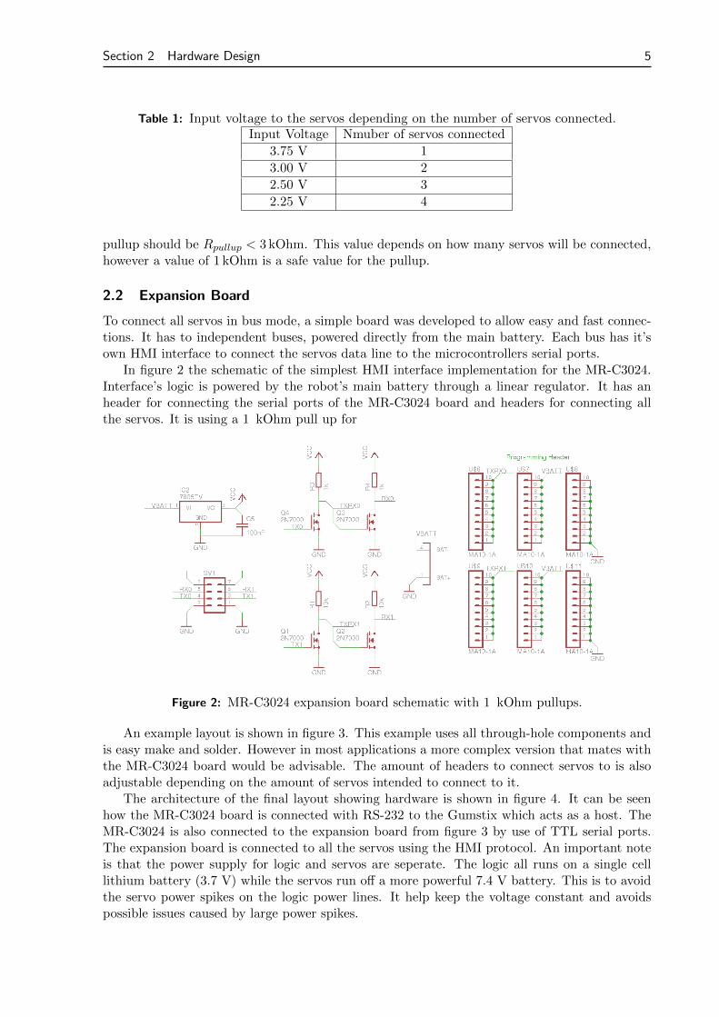
In figure 2 the schematic of the simplest HMI interface implementation for the MR-C3024.Interface’s logic is powered by the robot’s main battery through a linear regulator. It has anheader for connecting the serial ports of the MR-C3024 board and headers for connecting allthe servos. It is using a 1 kOhm pull up for
Figure 2: MR-C3024 expansion board schematic with 1 kOhm pullups.
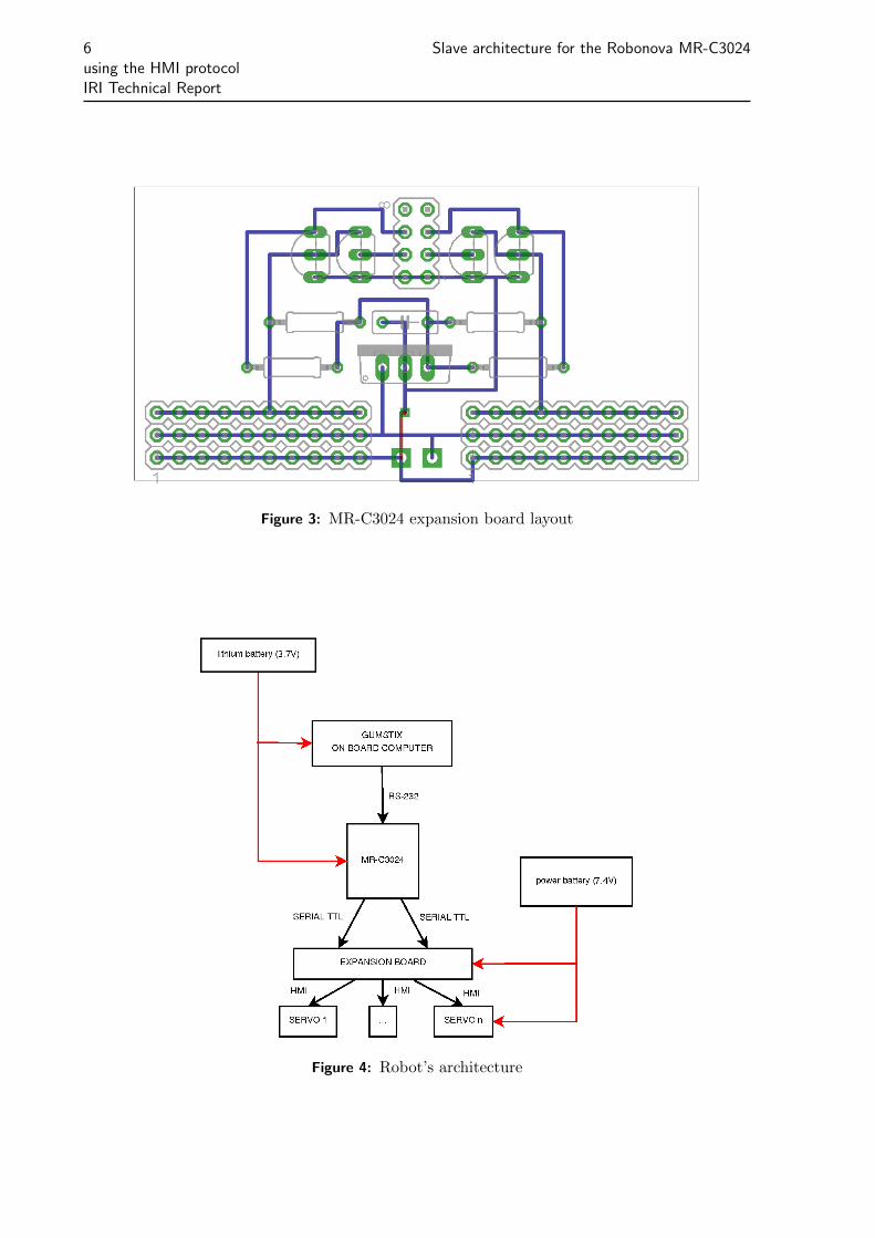
An example layout is shown in figure 3. This example uses all through-hole components andis easy make and solder. However in most applications a more complex version that mates withthe MR-C3024 board would be advisable. The amount of headers to connect servos to is alsoadjustable depending on the amount of servos intended to connect to it.
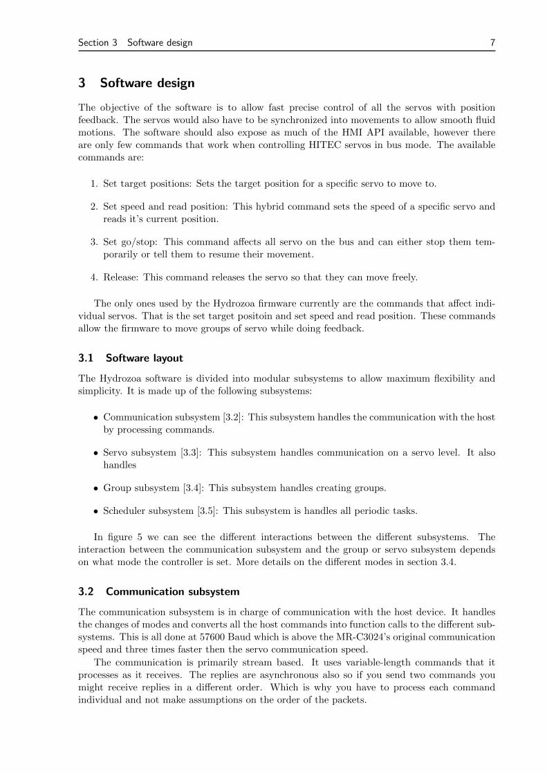
The architecture of the final layout showing hardware is shown in figure 4. It can be seenhow the MR-C3024 board is connected with RS-232 to the Gumstix which acts as a host. TheMR-C3024 is also connected to the expansion board from figure 3 by use of TTL serial ports.The expansion board is connected to all the servos using the HMI protocol. An important noteis that the power supply for logic and servos are seperate. The logic all runs on a single celllithium battery (3.7 V) while the servos run off a more powerful 7.4 V battery. This is to avoidthe servo power spikes on the logic power lines. It help keep the voltage constant and avoidspossible issues caused by large power spikes.
6 Slave architecture for the Robonova MR-C3024using the HMI protocolIRI Technical Report
Figure 3: MR-C3024 expansion board layout
Figure 4: Robot’s architecture
Section 3 Software design 7
3 Software design
The objective of the software is to allow fast precise control of all the servos with positionfeedback. The servos would also have to be synchronized into movements to allow smooth fluidmotions. The software should also expose as much of the HMI API available, however thereare only few commands that work when controlling HITEC servos in bus mode. The availablecommands are:
1. Set target positions: Sets the target position for a specific servo to move to.
2. Set speed and read position: This hybrid command sets the speed of a specific servo andreads it’s current position.
3. Set go/stop: This command affects all servo on the bus and can either stop them tem-porarily or tell them to resume their movement.
4. Release: This command releases the servo so that they can move freely.
The only ones used by the Hydrozoa firmware currently are the commands that affect indi-vidual servos. That is the set target positoin and set speed and read position. These commandsallow the firmware to move groups of servo while doing feedback.
3.1 Software layout
The Hydrozoa software is divided into modular subsystems to allow maximum flexibility andsimplicity. It is made up of the following subsystems:
• Communication subsystem [3.2]: This subsystem handles the communication with the hostby processing commands.
• Servo subsystem [3.3]: This subsystem handles communication on a servo level. It alsohandles
• Group subsystem [3.4]: This subsystem handles creating groups.
• Scheduler subsystem [3.5]: This subsystem is handles all periodic tasks.
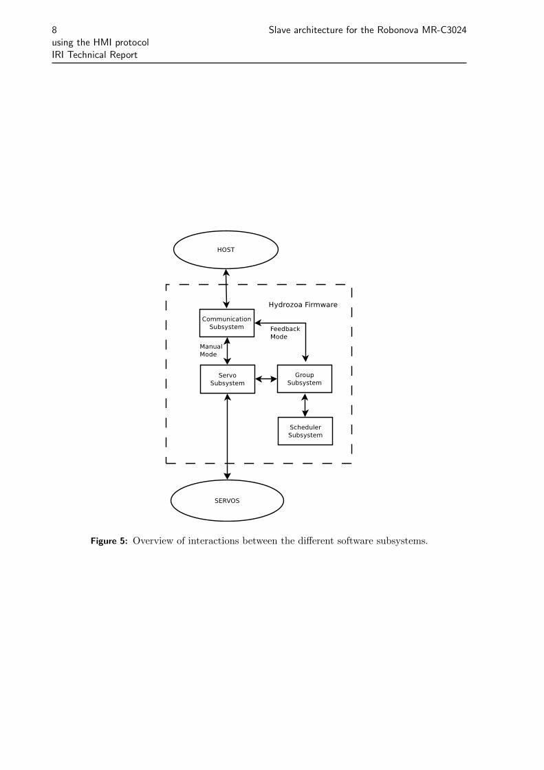
In figure 5 we can see the different interactions between the different subsystems. Theinteraction between the communication subsystem and the group or servo subsystem dependson what mode the controller is set. More details on the different modes in section 3.4.
3.2 Communication subsystem
The communication subsystem is in charge of communication with the host device. It handlesthe changes of modes and converts all the host commands into function calls to the different sub-systems. This is all done at 57600 Baud which is above the MR-C3024’s original communicationspeed and three times faster then the servo communication speed.
The communication is primarily stream based. It uses variable-length commands that itprocesses as it receives. The replies are asynchronous also so if you send two commands youmight receive replies in a different order. Which is why you have to process each commandindividual and not make assumptions on the order of the packets.
8 Slave architecture for the Robonova MR-C3024using the HMI protocolIRI Technical Report
Figure 5: Overview of interactions between the different software subsystems.
Section 3 Software design 9
3.3 Servo subsystem
The servo subsystem handles commands to individual servos. It is the lowest layer built aroundthe HMI protocol. It is designed only to reflect the commands the servos accept.
The ATmega128 MCU on the MR-C3024 board only has 2 hardware UARTs available. Sincethe board has to communicate with the host device (Gumstix PXA270) by rs232 that only leaves1 hardware UART available. To be able to work with position feedback, the communicationspeed would have to be optimized to allow as fast as possible feedback updates.
The HMI interface runs at 19200 BAUD with 2 stop bits. Each servo packet is 7 bytes inlength. We have to control 24 servos. That means that the maximum rate would be:
ffeedback =fbaud
Nservo ∗ Lpacket ∗ Lbits= 10.39 Hz ' 10 Hz
In order to increase the feedback speed to 20 Hz it was decided to split the 24 servos intotwo groups of 12. The more used group of 12 would use the hardware UART while the othergroup of 12 would use a software UART. In order to work with both hardware and softwareUART an abstraction layer was created to allow access to any type of UART independently ofit’s internal workings.
/∗∗∗ @br ie f Represents an uart .∗/
typedef struct Uart s {void (∗ putc ) ( u i n t 8 t c ) ; /∗∗< Puts a charac t e r on the UART. ∗/int (∗ s t a t u s ) ( void ) ; /∗∗< Checks to see i f ou tgo ing b u f f e r i s
empty , r e turns 1 i f empty . ∗/
/∗ Recieve b u f f e r s t u f f . ∗/int pos ; /∗∗< Current p o s i t i o n in the r e c i e v i n g b u f f e r . ∗/u i n t 8 t buf [ 6 ] ; /∗∗< Buf fer con ta in ing r e c i e v i n g data . ∗/
} Uart t ;
The abstraction only has functions for writing to the UART and checking it’s status. It’simportant to be able to check the UART status, because if the line hasn’t been communicatingfor a while the servos will desync with the MR-C3024. To avoid desynchronization they needto be sent 7 zero bytes before the actual package. Otherwise they may lose bytes causingthe communication to desynchronize and lose a command. Before sending any command thesoftware will check to see if the outgoing buffer is full, if it is not it will send the sync bytesbefore sending the actual command.
Another important thing to note is that the abstraction automatically handles the reply usinga small buffer with just enough information to contain each reply. This allows communicationto work transparently with many virtual UARTs.
3.4 Group subsystem
The group subsystem handles creating groups of servos. The Hydrozoa software allows twodifferent control modes: either individual servo control or group-based control. The individualmode is a simple way of having control of the servos. It only exposes the servo commands. Thegroup-based control mode is meant for synchronizing movements among groups of servos. It isthe most useful for the control of humanoid type robots.
The main feature of groups is the synchronization, but they also have the added advantageof being able to get feedback really fast. When a group is moving it will automatically be polled
10 Slave architecture for the Robonova MR-C3024using the HMI protocolIRI Technical Report
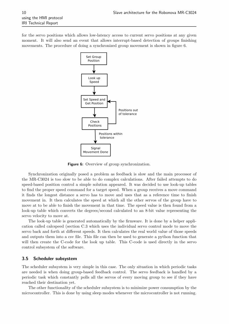
for the servo positions which allows low-latency access to current servo positions at any givenmoment. It will also send an event that allows interrupt-based detection of groups finishingmovements. The procedure of doing a synchronized group movement is shown in figure 6.
Figure 6: Overview of group synchronization.
Synchronization originally posed a problem as feedback is slow and the main processor ofthe MR-C3024 is too slow to be able to do complex calculations. After failed attempts to dospeed-based position control a simple solution appeared. It was decided to use look-up tablesto find the proper speed command for a target speed. When a group receives a move commandit finds the longest distance a servo has to move and uses that as a reference time to finishmovement in. It then calculates the speed at which all the other servos of the group have tomove at to be able to finish the movement in that time. The speed value is then found from alook-up table which converts the degrees/second calculated to an 8-bit value representing theservo velocity to move at.
The look-up table is generated automatically by the firmware. It is done by a helper appli-cation called calcspeed (section C.3 which uses the individual servo control mode to move theservo back and forth at different speeds. It then calculates the real world value of those speedsand outputs them into a csv file. This file can then be used to generate a python function thatwill then create the C-code for the look up table. This C-code is used directly in the servocontrol subsystem of the software.
3.5 Scheduler subsystem
The scheduler subsystem is very simple in this case. The only situation in which periodic tasksare needed is when doing group-based feedback control. The servo feedback is handled by aperiodic task which constantly polls all the servos of every moving group to see if they havereached their destination yet.
The other functionality of the scheduler subsystem is to minimize power consumption by themicrocontroller. This is done by using sleep modes whenever the microcontroller is not running.
Section 3 Software design 11
However power consumption of the microcontroller is usually negligible when compared to thepower consumption of the servos.
3.6 Host High level API
The high level API is built around the CRobot [9]. It wraps around the lower level firmwarecommands in a more flexible and dynamic matter. This also allows error detection and cor-rection. However the main advantage is being able to design and write applications using thefirmware functionality much faster than otherwise.
The concept of the high level API is basically based around the entire group API. The properway to use the API is to follow some simple steps:
1. Initialize the class.
2. Create the servo group.
3. Set the servo group settings (optional).
4. Issue group commands.
The API focuses on groups and using them. Some of the more important functions are:
• get maxGroup: Gets the maximum available amount of groups.
• grp create: Creates a group of servos.
• grp destroy: Destroys a group of servos.
• grp move: Moves a group of servos.
• grp stop: Stops the movement of a group.
• grp waitDone: Waits until a gorup finishes moving.
• grp setTol: Sets the tolerance of a gorup.
• grp isDone: Checks to see if a group is done moving.
• grp feedback: Gets the position feedback for a gorup.
• grp setSpeed: Sets the maximum group target speed.
3.7 Unit Tests
To be able to rapidly test the functionality of the firmware and guarantee that it is workingperfectly some unit tests were designed. These are automated tests that allow quick testing ofall the features of the firmware. If anything goes wrong or there is any issue with the firmwareit will be detected and the developer will be informed to be able to correct this. This is veryimportant to be able to have a robust and reliable firmware.
The unit tests consist of a single application that runs through the entire API testing all thedifferent commands and verifies the execution of them. The single application has been called’testfirmware’ (see section C.2) and is available in the source code repository. The executionis straight forward, the electronics board has to be plugged in with some servos connected.Afterwards the testfirmware command is executed with the path to the rs232 port as a parameterand it will begin execution. If all is successfully it will run through all the commands and printa message indicating success.
12 Slave architecture for the Robonova MR-C3024using the HMI protocolIRI Technical Report
4 Testing
To ensure the reliability and quality of the Hydrozoa firmware, a standard procedure and appli-cations (see section C) for testing were developed.
4.1 Getting Started
The standard procedure for setting up servos to work with Hydrozoa firmware is the following:
1. Program servo ids with the setid command of testservo (see section C.1.3). Make sure theservo ids do not overlap.
2. Program the MR-C3024 board to use the Hydrozoa Firmware (see section B.4).
3. Connect the MR-C3024 board to the Expansion board.
4. Connect the servos to the expansion board. Try to distribute servos evenly on both UARTs.The most used servos should ideally go on the hardware UART.
5. Connect the MR-C3024 board to the Host.
6. Run tests (see section C.2) to ensure everything is working properly.
7. Start using the library (see section A).
These steps are all crucial to making sure everything is working properly.
4.2 Calibration
Speed Value
Actu
al Speed
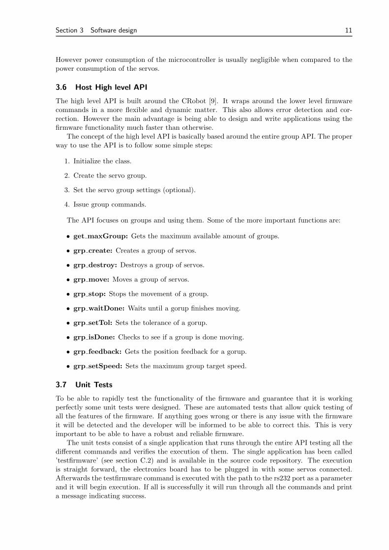
Figure 7: An approximation of the HSR-8498 servo speed curve
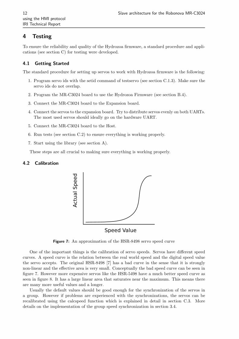
One of the important things is the calibration of servo speeds. Servos have different speedcurves. A speed curve is the relation between the real world speed and the digital speed valuethe servo accepts. The original HSR-8498 [7] has a bad curve in the sense that it is stronglynon-linear and the effective area is very small. Conceptually the bad speed curve can be seen infigure 7. However more expensive servos like the HSR-5498 have a much better speed curve asseen in figure 8. It has a large linear area that saturates near the maximum. This means thereare many more useful values and a longer.
Usually the default values should be good enough for the synchronization of the servos ina group. However if problems are experienced with the synchronizations, the servos can berecalibrated using the calcspeed function which is explained in detail in section C.3. Moredetails on the implementation of the group speed synchronization in section 3.4.
Section 4 Testing 13
Speed ValueA
ctu
al Speed
Figure 8: An approximation of the HSR-5498 servo speed curve
4.3 Experimental Setup
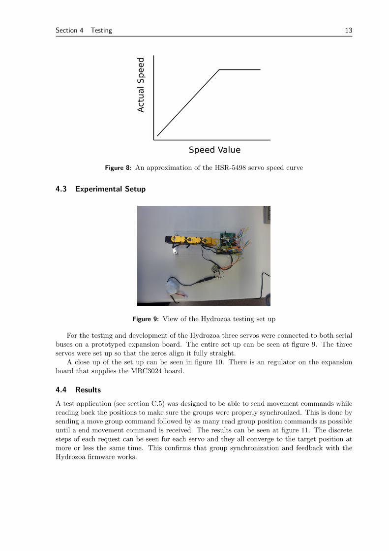
Figure 9: View of the Hydrozoa testing set up
For the testing and development of the Hydrozoa three servos were connected to both serialbuses on a prototyped expansion board. The entire set up can be seen at figure 9. The threeservos were set up so that the zeros align it fully straight.
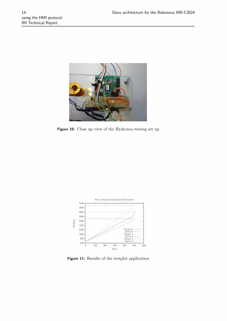
A close up of the set up can be seen in figure 10. There is an regulator on the expansionboard that supplies the MRC3024 board.
4.4 Results
A test application (see section C.5) was designed to be able to send movement commands whilereading back the positions to make sure the groups were properly synchronized. This is done bysending a move group command followed by as many read group position commands as possibleuntil a end movement command is received. The results can be seen at figure 11. The discretesteps of each request can be seen for each servo and they all converge to the target position atmore or less the same time. This confirms that group synchronization and feedback with theHydrozoa firmware works.
14 Slave architecture for the Robonova MR-C3024using the HMI protocolIRI Technical Report
Figure 10: Close up view of the Hydrozoa testing set up
600
800
1000
1200
1400
1600
1800
2000
2200
2400
0 100 200 300 400 500 600
Position
Time
Servo Group Synchronized Movement
Target 0Servo 0Target 1Servo 1Target 2Servo 2
Figure 11: Results of the testplot application
Section 5 Conclusions and Future Work 15
5 Conclusions and Future Work
The implementation is working well. The replacement firmware is optimized for servo groupsynchronization and movement and is up to the task. Many features have been added to improvethe handling of the servos. The resulting movement is smooth and fluid.
A movement subsystem has been also added to the CRobot library to allow easy usage ofthe firmware. In the repository there are examples in section A on how to use this subsystemto control some servos.
For the future it would be interesting to develop a new robust firmware uploader. The cur-rent one (section B) is a windows application that has some bugs that have not been addressed.For smoother movements, an internal queue could be added, so the microcontroller could chainsynchronized movements. A flexible implementation of inverse kinematics for humanoids wouldalso be interesting to integrate into the CRobot movement subsystem developed for this appli-cation. It would also be good to expose more functionality of the MR-C3024 board throughthe Hydrozoa firmware, like ADC ports, buzzer, multi-purpose i/o, etc... There is still room forimprovement and evolution.
More information about this project can be found at the official project web page:http://apollo.upc.es/humanoide/
16 REFERENCES
References
[1] Various Authors. Finally cracked!http://robosavvy.com/forum/viewtopic.php?t=271&postdays=0&postorder=
asc&start=60, 2010.
[2] Generalitat de Catalunya. Generalitat de catalunya.http://www.gencat.cat/, 2010.
[3] Richard Ibbotson. Hitec HSR-8498HB Digital Servo Operation and Interface.http://robosavvy.com/Builders/i-Bot/HSR8498HB%20Servo.pdf, 2010.
[4] Institut de Robotica i Informatica Industrial. CSIC-IRI Website.http://www.iri.upc.edu/, 2010.
[5] La Farga. Beques de programari lliure.http://www.lafarga.cat/beques/, 2008.
[6] miniROBOT Corp. roboBASIC Home.http://www.robobasic.com/, 2010.
[7] Hitec Robotics. HSR-8498HB HMI Standard Robot Servo.http://www.hitecrcd.com/products/servos/robotics/hsr-8498hb.html, 2010.
[8] Hitec Robotics. Robot Controller - MR-C3024.http://www.hitecrobotics.com/product/proB_02.html, 2010.
[9] The Humanoid Lab Team. CRobot Git Repository.http://apollo.upc.es/gitweb/?p=crobot.git;a=summary, 2010.
[10] The Humanoid Lab Team. The Humanoid Lab Website.http://apollo.upc.es/humanoide/, 2010.
Section A Using the CRobot Library 17
A Using the CRobot Library
This is a guide on how to get started using the software here presented.
1. Get, compile and install CRobot library. In [10] is extensively explained.
note: this library can be tested on any computer, laptop or PC embedded, that runs Linux.
2. Get and compile hydrozoa library. You can get it freely from:
$ g i t c l one g i t : // a p o l l o . upc . es / hydrozoa . g i t
Read COMPILE to check it’s dependencies and also a quick how-to.
3. Upload new firmware to MR-C3024 board. You can use a windows app. Found inRoboFlash directory inside hydrozoa repository. Just connect the serial cable as you’ddo for uploading a robobasic program.
4. Go back to CRobot repository.
$ cd test /momvement$ . / testmoves . bin
5. You should read ”successfully moved all servos”.
18 Slave architecture for the Robonova MR-C3024using the HMI protocolIRI Technical Report
B MR-C3024 bootloader
Generally, a bootloader is a small program which runs at boot time and is capable of loading acomplete application program into a processor’s memory so that it can be executed. Note thatthe bootloader runs on the same processor into which it is loading a new program.
B.1 Why we need a bootloader?
In the case of AVR processors, the bootloader program is usually 256-4096 assembly instructionslong and resides in a special portion of the FLASH memory called the bootblock. At boot time(when the processor has just been reset) the bootloader starts and is capable of communicatingwith the outside world to retrieve a new program and program it into the processor’s FLASHmemory. Depending on the bootloader and the available hardware, new application code canbe loaded from any source including the serial port, SPI or I2C interfaces, external memory,hard disks, flash cards, etc. Once the programming is done, the bootloader program exits orthe processor is reset, begins running the newly loaded code. Only AVR processors with theself-programming memory feature (those that have an SPM assembly instruction) can run abootloader.
This is the case of the ATmega128, the brain of the MR-C3024. It has a proprietary boot-loader protected with a custom serial protocol.
B.2 Reverse engineering
Thanks to the effort carried out the by people at robosavvy.com [1], the bootloader sequencewas finally decrypted.
B.3 Bootloader sequence and algorithm
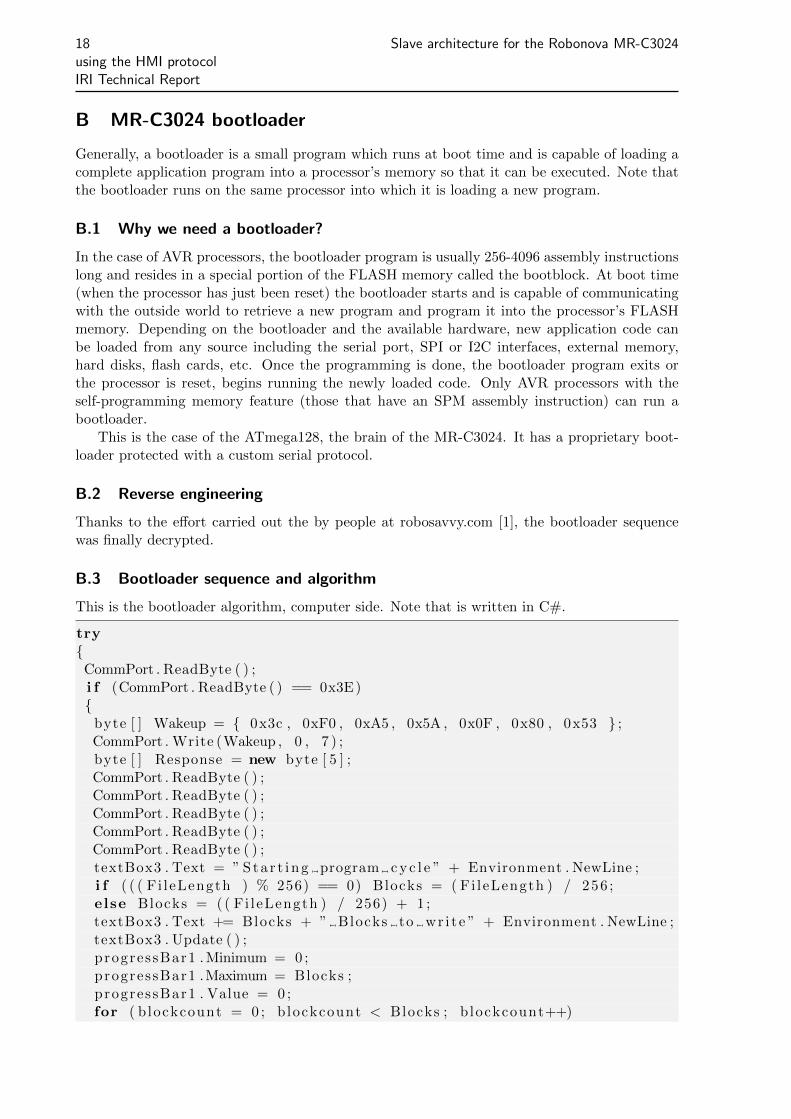
This is the bootloader algorithm, computer side. Note that is written in C#.
try{CommPort . ReadByte ( ) ;i f (CommPort . ReadByte ( ) == 0x3E){
byte [ ] Wakeup = { 0x3c , 0xF0 , 0xA5 , 0x5A , 0x0F , 0x80 , 0x53 } ;CommPort . Write (Wakeup , 0 , 7 ) ;byte [ ] Response = new byte [ 5 ] ;CommPort . ReadByte ( ) ;CommPort . ReadByte ( ) ;CommPort . ReadByte ( ) ;CommPort . ReadByte ( ) ;CommPort . ReadByte ( ) ;textBox3 . Text = ” Sta r t i ng program c y c l e ” + Environment . NewLine ;i f ( ( ( Fi leLength ) % 256) == 0) Blocks = ( Fi leLength ) / 256 ;else Blocks = ( ( Fi leLength ) / 256) + 1 ;textBox3 . Text += Blocks + ” Blocks to wr i t e ” + Environment . NewLine ;textBox3 . Update ( ) ;progressBar1 . Minimum = 0 ;progressBar1 .Maximum = Blocks ;progressBar1 . Value = 0 ;for ( b lockcount = 0 ; blockcount < Blocks ; b lockcount++)
Section B MR-C3024 bootloader 19
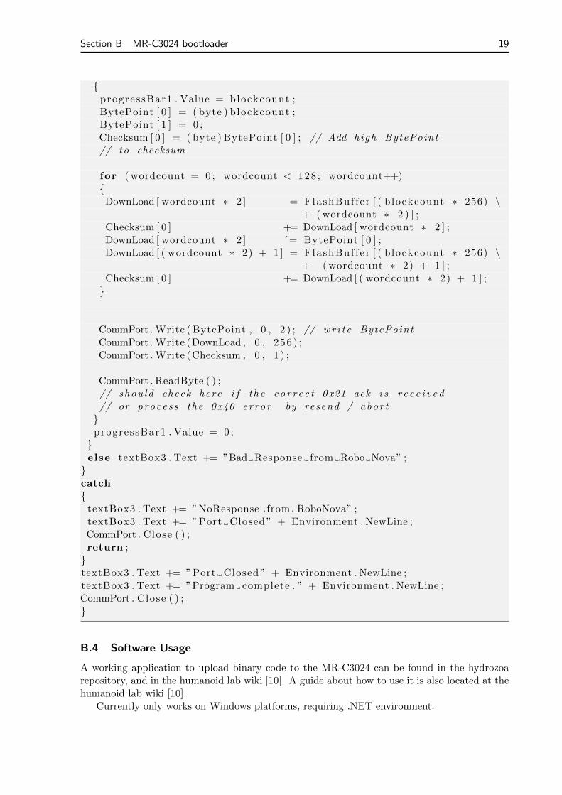
{progressBar1 . Value = blockcount ;BytePoint [ 0 ] = ( byte ) blockcount ;BytePoint [ 1 ] = 0 ;Checksum [ 0 ] = ( byte ) BytePoint [ 0 ] ; // Add high BytePoint// to checksum
for ( wordcount = 0 ; wordcount < 128 ; wordcount++){
DownLoad [ wordcount ∗ 2 ] = FlashBuf f e r [ ( b lockcount ∗ 256) \+ ( wordcount ∗ 2 ) ] ;
Checksum [ 0 ] += DownLoad [ wordcount ∗ 2 ] ;DownLoad [ wordcount ∗ 2 ] ˆ= BytePoint [ 0 ] ;DownLoad [ ( wordcount ∗ 2) + 1 ] = FlashBuf f e r [ ( b lockcount ∗ 256) \
+ ( wordcount ∗ 2) + 1 ] ;Checksum [ 0 ] += DownLoad [ ( wordcount ∗ 2) + 1 ] ;}
CommPort . Write ( BytePoint , 0 , 2 ) ; // wr i t e BytePointCommPort . Write (DownLoad , 0 , 2 5 6 ) ;CommPort . Write (Checksum , 0 , 1 ) ;
CommPort . ReadByte ( ) ;// shou ld check here i f the co r r e c t 0x21 ack i s r e c e i v ed// or proces s the 0x40 error by resend / abor t}progressBar1 . Value = 0 ;}else textBox3 . Text += ”Bad Response from Robo Nova” ;}catch{
textBox3 . Text += ”NoResponse from RoboNova” ;textBox3 . Text += ”Port Closed ” + Environment . NewLine ;CommPort . Close ( ) ;return ;}textBox3 . Text += ”Port Closed ” + Environment . NewLine ;textBox3 . Text += ”Program complete . ” + Environment . NewLine ;CommPort . Close ( ) ;}
B.4 Software Usage
A working application to upload binary code to the MR-C3024 can be found in the hydrozoarepository, and in the humanoid lab wiki [10]. A guide about how to use it is also located at thehumanoid lab wiki [10].
Currently only works on Windows platforms, requiring .NET environment.
20 Slave architecture for the Robonova MR-C3024using the HMI protocolIRI Technical Report
C Software Documentation
For testing purposes that are various applications for interacting with the newly developedfirmware. All these applications unless otherwise specified are designed to run on Linux and inthe console. When showing example usage, the ’$’ symbol represents the console prompt.
C.1 testservo
This application is for testing with the standalone servo board. The application provides directcalls for controlling all of the HMI servo commands. It also provides higher level functions likeone for setting the ID of the servo.
C.1.1 Compilation
To compile the application, from the root of the hydrozoa repository run the following command:
$ cd t e s t s e r v o$ make
If there is any error, please read it carefully to see what you may be missing.
C.1.2 Usage
To use the application just run it with the path to the serial port and the command you want toexecute. For example to stop all the servos on a device connected through a serial-usb converteryou would generally use:
$ . / t e s t s e r v o /dev/ttyUSB0 stop
When testservo is run with invalid parameters it will display the usage. You can also makeit display by calling it with no parameters like:
$ . / t e s t s e r v o
C.1.3 Setting the ID
The main functionality of the testservo application is to set the ID of a servo. Some notes onsetting the id:
1. Only one servo may be connected when setting the ID.
2. The valid ids for servos go from 0-127 inclusive. They are in decimal and not hexadecimal.
3. If there are any errors, make sure to run it again until it succeeds or the servo will notwork anymore.
An example usage of the setid command is:
$ . / t e s t s e r v o /dev/ttyUSB0 s e t i d 0
C.2 testfirmware
The testfirmware is an standalone application designed for testing all the API of the Hydrozoafirmware. It is capable of working with any number of servos but it is recommended to at leastuse two servos, one on each bus. The servos should also have consecutive IDs.
Section C Software Documentation 21
C.2.1 Compilation
To compile the application, from the root of the hydrozoa repository run the following command:
$ cd t e s t f i rmware$ make
If there is any error, please read it carefully to see what you may be missing.
C.2.2 Usage
To use the application just run it from the console as such:
$ . / t e s t f i rmware
It should then proceed to display information of what it’s doing while it moves the servos.It should also autodetect all the connected servos so it’s a good way of seeing what servos areconnected.
C.3 calcspeed
WARNING! THIS APPLICATION MAY BURN OUT YOUR SERVO, USE WITH CAUTION.The calcspeed application is for calibrating the servo speed by creating a look up table
that allows the Hydrozoa firmware to properly synchronize groups by relative the HMI speedcommand value with the servo real speed.
C.3.1 Compilation
See C.2.1.
C.3.2 Usage
The procedure to run calcspeed is simple. Just make sure you stop it before it burns the servoout, usually once it reaches around 200 speed. To do this type control+C and the runningcommand should stop. To run it and generate the speed data use the following command:
$ . / ca l c speed # Remember to k i l l i t b e f o r e i t k i l l s the servo
Now you should open the newly generated servo tune.csv with your statistic program ofchoice and generate functions that approximate the results. To then generate the look up tableyou should then edit create lookup.py and change the function ”def f(x):” so that it returns thevalues of the function you found that approximates the result. The default function used is:
def f ( x ) :i f x >= 144 :
return −3e−5 ∗ x∗∗2 + 0.03544 ∗ x + 245 .7e l i f x < 144 and x >= 52 :
return 2e−5 ∗ x∗∗3 − 6 .8 e−3 ∗ x∗∗2 + 0.8463 ∗ x + 210 .5e l i f x < 52 and x >= 18 :
return 0 .001 ∗ x∗∗3 − 0 .1315 ∗ x∗∗2 + 6.1904 ∗ x + 131.81else :
return 0
Next you should run the create lookup.py to generate the results with the following com-mand:
$ . / c r ea t e l ookup . py
22 Slave architecture for the Robonova MR-C3024using the HMI protocolIRI Technical Report
You should now have a servo tune.c file. This is the calibration file. Double check to makesure it was generated properly. If you are happy with the results, copy it over to src/servo tune.cand recompile the Hydrozoa firmware. When you upload it, it should now be using the look uptable you created.
C.4 testspeed
The testspeed application runs multiple speed commands to test the actual velocity of the servo.It is a good way to check if the lookup table for servo movement synchronization is good or if itneeds to be adjusted.
C.4.1 Compilation
See C.2.1.
C.4.2 Usage
To use the application run it with:
$ . / t e s t s p e ed
The console should then output the results.
C.5 testplot
The testplot application is a subset of the testfirmware application and it’s only use is to generatea plot that verifies that the hydrozoa is indeed doing group synchronization. It must be usedwith three servos with ids of 0, 1 and 2 connected to it with free movement range.
C.5.1 Compilation
See C.2.1.
C.5.2 Usage
To generate the image run:
$ . / t e s t p l o t

HydrozoaVersion
Edgar SimoJordi Pegueroles
January 13, 2011
Chapter 1
Module Index
1.1 Modules
Here is a list of all modules:
UART Library . . . . . . . . . . . . . . . . . . . . . . . . . . . . . . . . . . . . . . . . . . . 7Software UART Library . . . . . . . . . . . . . . . . . . . . . . . . . . . . . . . . . . . . . 13

2 Module Index
Hydrozoa V
Chapter 2
Data Structure Index
2.1 Data Structures
Here are the data structures with brief descriptions:
Group_s (Represents a group of servos ) . . . . . . . . . . . . . . . . . . . . . . . . . . . . 17Servo_s (Represents a servo ) . . . . . . . . . . . . . . . . . . . . . . . . . . . . . . . . . . 19Uart_s (Represents an uart ) . . . . . . . . . . . . . . . . . . . . . . . . . . . . . . . . . . . 20

4 Data Structure Index
Hydrozoa V
Chapter 3
File Index
3.1 File List
Here is a list of all documented files with brief descriptions:
comm.h . . . . . . . . . . . . . . . . . . . . . . . . . . . . . . . . . . . . . . . . . . . . . . ??conf.h . . . . . . . . . . . . . . . . . . . . . . . . . . . . . . . . . . . . . . . . . . . . . . . ??sched.h . . . . . . . . . . . . . . . . . . . . . . . . . . . . . . . . . . . . . . . . . . . . . . . ??servo.h . . . . . . . . . . . . . . . . . . . . . . . . . . . . . . . . . . . . . . . . . . . . . . . ??uart.h . . . . . . . . . . . . . . . . . . . . . . . . . . . . . . . . . . . . . . . . . . . . . . . . ??uartsw.c (Full duplex software and interrupt driven uart ) . . . . . . . . . . . . . . . . . . 21uartsw.h . . . . . . . . . . . . . . . . . . . . . . . . . . . . . . . . . . . . . . . . . . . . . . ??

6 File Index
Hydrozoa V
Chapter 4
Module Documentation
4.1 UART Library
Interrupt UART library using the built-in UART with transmit and receive circular buffers.
Defines
• #define UART_BAUD_SELECT(baudRate, xtalCpu) ((xtalCpu)/((baudRate)∗16l)-1)UART Baudrate Expression.
• #define UART_BAUD_SELECT_DOUBLE_SPEED(baudRate, xtal-Cpu) (((xtalCpu)/((baudRate)∗8l)-1)|0x8000)
UART Baudrate Expression for ATmega double speed mode.
• #define UART_TX_BUFFER_SIZE 128• #define UART_FRAME_ERROR 0x0800• #define UART_OVERRUN_ERROR 0x0400• #define UART_BUFFER_OVERFLOW 0x0200• #define UART_NO_DATA 0x0100• #define uart_puts_P(__s) uart_puts_p(PSTR(__s))
Macro to automatically put a string constant into program memory.
• #define uart1_puts_P(__s) uart1_puts_p(PSTR(__s))Macro to automatically put a string constant into program memory.
Functions
• void uart_init (unsigned int baudrate)Initialize UART and set baudrate.
• void uart_setFunc (void(∗func)(uint8_t))Sets function to call when byte is recieved.
8 Module Documentation
• unsigned int uart_getc (void)Get received byte from ringbuffer.
• int uart_status (void)Check the status of the output buffer.
• void uart_putc (unsigned char data)Put byte to ringbuffer for transmitting via UART.
• void uart_puts (const char ∗s)Put string to ringbuffer for transmitting via UART.
• void uart_puts_p (const char ∗s)Put string from program memory to ringbuffer for transmitting via UART.
• void uart1_init (unsigned int baudrate)Initialize USART1 (only available on selected ATmegas).
• void uart1_setFunc (void(∗func)(uint8_t))Sets the functiion to call when UART1 recieves data.
• unsigned int uart1_getc (void)Get received byte of USART1 from ringbuffer. (only available on selected ATmega).
• int uart1_status (void)Check the status of the output buffer.
• void uart1_putc (unsigned char data)Put byte to ringbuffer for transmitting via USART1 (only available on selected ATmega).
• void uart1_puts (const char ∗s)Put string to ringbuffer for transmitting via USART1 (only available on selected ATmega).
• void uart1_puts_p (const char ∗s)Put string from program memory to ringbuffer for transmitting via USART1 (only available on selectedATmega).
4.1.1 Detailed Description
#include <uart.h>
This library can be used to transmit and receive data through the built in UART.
An interrupt is generated when the UART has finished transmitting or receiving a byte. Theinterrupt handling routines use circular buffers for buffering received and transmitted data.
The UART_RX_BUFFER_SIZE and UART_TX_BUFFER_SIZE constants define the size of the cir-cular buffers in bytes. Note that these constants must be a power of 2. You may need to adaptthis constants to your target and your application by adding CDEFS += -DUART_RX_BUFFER_-SIZE=nn -DUART_RX_BUFFER_SIZE=nn to your Makefile.
Hydrozoa V
4.1 UART Library 9
Note
Based on Atmel Application Note AVR306
Author
Peter Fleury [email protected] http://jump.to/fleury
4.1.2 Define Documentation
4.1.2.1 #define UART_BAUD_SELECT(baudRate, xtalCpu) ((xtalCpu)/((baudRate)∗16l)-1)
Parameters
xtalcpu system clock in Mhz, e.g. 4000000L for 4Mhzbaudrate baudrate in bps, e.g. 1200, 2400, 9600
4.1.2.2 #define UART_BAUD_SELECT_DOUBLE_SPEED(baudRate,xtalCpu) (((xtalCpu)/((baudRate)∗8l)-1)|0x8000)
Parameters
xtalcpu system clock in Mhz, e.g. 4000000L for 4Mhzbaudrate baudrate in bps, e.g. 1200, 2400, 9600
4.1.2.3 #define UART_TX_BUFFER_SIZE 128
Size of the circular receive buffer, must be power of 2 Size of the circular transmit buffer, must bepower of 2
4.1.3 Function Documentation
4.1.3.1 unsigned int uart1_getc (void)
See also
uart_getc
4.1.3.2 void uart1_init (unsigned int baudrate)
See also
uart_init
4.1.3.3 void uart1_putc (unsigned char data)
See also
uart_putc
Hydrozoa V
10 Module Documentation
4.1.3.4 void uart1_puts (const char ∗ s)
See also
uart_puts
4.1.3.5 void uart1_puts_p (const char ∗ s)
See also
uart_puts_p
4.1.3.6 unsigned int uart_getc (void)
Returns in the lower byte the received character and in the higher byte the last receive error.UART_NO_DATA is returned when no data is available.
Parameters
void
Returns
lower byte: received byte from ringbufferhigher byte: last receive status
• 0 successfully received data from UART
• UART_NO_DATAno receive data available
• UART_BUFFER_OVERFLOWReceive ringbuffer overflow. We are not reading the receive buffer fast enough, one ormore received character have been dropped
• UART_OVERRUN_ERROROverrun condition by UART. A character already present in the UART UDR registerwas not read by the interrupt handler before the next character arrived, one or morereceived characters have been dropped.
• UART_FRAME_ERRORFraming Error by UART
4.1.3.7 void uart_init (unsigned int baudrate)
Parameters
baudrate Specify baudrate using macro UART_BAUD_SELECT()
Returns
none
Hydrozoa V

4.1 UART Library 11
4.1.3.8 void uart_putc (unsigned char data)
Parameters
data byte to be transmitted
Returns
none
4.1.3.9 void uart_puts (const char ∗ s)
The string is buffered by the uart library in a circular buffer and one character at a time is trans-mitted to the UART using interrupts. Blocks if it can not write the whole string into the circularbuffer.
Parameters
s string to be transmitted
Returns
none
4.1.3.10 void uart_puts_p (const char ∗ s)
The string is buffered by the uart library in a circular buffer and one character at a time is trans-mitted to the UART using interrupts. Blocks if it can not write the whole string into the circularbuffer.
Parameters
s program memory string to be transmitted
Returns
none
See also
uart_puts_P
4.1.3.11 void uart_setFunc (void(∗)(uint8_t) func)
Parameters
Function to hook to byte recieve.
Returns
None
248 : Sets the UART recieving function.249 Purpose: called when the UART has received a character250 **************************************************************************/251 {252 uart_recvFunc = func;253 }
Hydrozoa V

12 Module Documentation
4.1.3.12 int uart_status (void)
Returns
1 if the output buffer is empty.
Hydrozoa V
4.2 Software UART Library 13
4.2 Software UART Library
Interrupt driven full duplex software UART library using the built-in Timer0, Timer2 and exter-nal int. 0, with transmit circular buffers.
Defines
• #define BR_19200
Desired baudrate...choose one, comment the others.
• #define __AVR_ATmega128__
Enumerations
• enum AsynchronousStatesTX_t {
TX_IDLE, TX_START, TX_TRANSMIT, TX_TRANSMIT_STOP_BIT1,
TX_TRANSMIT_STOP_BIT2 }
Type defined enumeration holding software UART’s state.
• enum AsynchronousStatesRX_t { RX_IDLE, RX_RECEIVE, RX_DATA_PENDING }
Type defined enumeration holding software UART’s state.
Functions
• void uartsw_init (void)
Initialize software UART.
• void uartsw_putc (unsigned char data)
Put byte to ringbuffer for transmitting via software UART.
• int uartsw_status (void)• void uartsw_setFunc (void(∗func)(uint8_t))
Sets the recieve function callback for the sw uart.
Variables
• volatile AsynchronousStatesRX_t stateRX
Holds the state of the UART.
• volatile unsigned char SwUartRXData
Storage for received bits.
Hydrozoa V
14 Module Documentation
4.2.1 Detailed Description
#include <swuart.h>
This library can be used to transmit and receive data through a software UART.
Timer0 is set to overflow at desired baud rate to recieve a byte. Timer0 is triguered by externalinterrupt 0, thus RX pin must be tied to an external interrupt. Each byte is stored in a globallyaccessible variable, and only last received byte is available. Timer is idle while not receiveing.
Timer2 is used to transmit a byte. Timer2 is set to overflow at desired baud rate. ISR is activewhile there is data in the circular buffer. Timer2 is idle if there is no data to be send.
The SWUART_TX_BUFFER_SIZE constant define the size of the circular buffer in bytes. Notethat this constant must be a power of 2. You may need to adapt this constant to your target andyour application by adding CDEFS += -DUART_RX_BUFFER_SIZE=nn to your Makefile.
Footprint: 750 bytes of ROM 40 bytes of RAM
Note
Based on Atmel Application Note AVR304
Author
Jordi Pegueroles [email protected] http://80.32.95.100
4.2.2 Define Documentation
4.2.2.1 #define __AVR_ATmega128__
Size of the circular transmit buffer, must be power of 2
4.2.3 Enumeration Type Documentation
4.2.3.1 enum AsynchronousStatesRX_t
Enumerator:
RX_IDLE Idle state.
RX_RECEIVE Receiveing a byte.
RX_DATA_PENDING Data pending.
85 {86 RX_IDLE,87 RX_RECEIVE,88 RX_DATA_PENDING8990 }AsynchronousStatesRX_t;
4.2.3.2 enum AsynchronousStatesTX_t
Enumerator:
TX_IDLE Idle state.
Hydrozoa V
4.2 Software UART Library 15
TX_START Transmitting start bit.
TX_TRANSMIT Transmitting byte.
TX_TRANSMIT_STOP_BIT1 Transmitting stop bit.
TX_TRANSMIT_STOP_BIT2 Transmitting stop bit.
71 {72 TX_IDLE,73 TX_START,74 TX_TRANSMIT,75 TX_TRANSMIT_STOP_BIT1,76 TX_TRANSMIT_STOP_BIT2,7778 }AsynchronousStatesTX_t;
4.2.4 Function Documentation
4.2.4.1 void uartsw_init (void)
Initialize software UART.
This function will set up pins to transmit and receive on. Control of Timer0, Timer2 and Externalinterrupt 0.
Parameters
void
Return values
void
References RX_IDLE, stateRX, stateTX, and TX_IDLE.
293 {294 SWUART_TxHead = 0;295 SWUART_TxTail = 0;296297 //PORT298 TRXPORT |= ( 1 << RX_PIN ); // RX_PIN is input, tri-stated.299 TRXDDR |= ( 1 << TX_PIN ); // TX_PIN is output.300 SET_TX_PIN( ); // Set the TX line to idle state.301302 // Timer0303 DISABLE_TIMER0_INTERRUPT( );304 TCCR0 = 0x00; // Init.305 TCCR0_P = 0x00; // Init.306 TCCR0 |= (1 << WGM01); // Timer in CTC mode.307 TCCR0_P |= ( 1 << CS01 ); // Divide by 8 prescaler.308309 // Timer2310 DISABLE_TIMER2_INTERRUPT( );311 OCR2 = TICKS2WAITONE; // Count one period.312 TCCR2 = 0x00; // Init.313 TCCR2_P = 0x00; // Init.314 TCCR2 |= ( 1 << WGM21 ); // Timer in CTC mode.315 TCCR2_P |= ( 1 << CS21 ); // Divide by 8 prescaler.316317 //External interrupt318 EXT_ICR = 0x00; // Init.319 EXT_ICR |= ( 1 << ISC01 ); // Interrupt sense control: falling edge.
Hydrozoa V
16 Module Documentation
320 ENABLE_EXTERNAL0_INTERRUPT( ); // Turn external interrupt on.321322 //Internal State Variable323 stateRX = RX_IDLE;324 stateTX = TX_IDLE;325 }
4.2.4.2 void uartsw_putc (const unsigned char c)
Put byte to ringbuffer for transmitting via software UART.
This function sends a unsigned char on the TX_PIN using the timer2 isr.
Note
uartsw_init( void ) must be called in advance.
Parameters
c unsigned char to transmit.
Return values
void
References stateTX, TX_IDLE, and TX_START.
340 {341 unsigned char tmphead;342343 tmphead = (SWUART_TxHead + 1) & SWUART_TX_BUFFER_MASK;344345 while ( tmphead == SWUART_TxTail ){346 ;/* wait for free space in buffer */347 }348349 SWUART_TxBuf[tmphead] = c;350 SWUART_TxHead = tmphead;351352 if ( stateTX == TX_IDLE ) {353 stateTX = TX_START;354 TCCR2_P &= ~( 1 << CS01 ); // Reset prescaler counter.355 TCNT2 = 0; // Clear counter register.356 TCCR2_P |= ( 1 << CS01 ); // CTC mode. Start prescaler clock.357 ENABLE_TIMER2_INTERRUPT( ); // Enable interrupt358 }359360 }/* uart_putc */
4.2.4.3 int uartsw_status (void)
Checks to see if the send buffer is empty.
364 {365 if ( SWUART_TxHead == SWUART_TxTail )366 return 1;367 return 0;368369 }
Hydrozoa V
Chapter 5
Data Structure Documentation
5.1 Group_s Struct Reference
Represents a group of servos.
Data Fields
• GroupState_t state• uint8_t tol• uint8_t size• uint8_t servos [SERVO_MAX]• uint8_t speed
5.1.1 Field Documentation
5.1.1.1 uint8_t Group_s::servos[SERVO_MAX]
IDs of the servos.
5.1.1.2 uint8_t Group_s::size
Size of the group.
5.1.1.3 uint8_t Group_s::speed
Speed to go at in grad/s.
5.1.1.4 GroupState_t Group_s::state
State of the group.

18 Data Structure Documentation
5.1.1.5 uint8_t Group_s::tol
Group tolerance.
The documentation for this struct was generated from the following file:
• servo.c
Hydrozoa V
5.2 Servo_s Struct Reference 19
5.2 Servo_s Struct Reference
Represents a servo.
Data Fields
• uint8_t uart• uint8_t speed• uint16_t target• uint16_t pos
5.2.1 Field Documentation
5.2.1.1 uint16_t Servo_s::pos
Servo’s current position.
5.2.1.2 uint8_t Servo_s::speed
Servo’s current speed.
5.2.1.3 uint16_t Servo_s::target
Servo’s target position.
5.2.1.4 uint8_t Servo_s::uart
Which uart the servo is on.
The documentation for this struct was generated from the following file:
• servo.c
Hydrozoa V
20 Data Structure Documentation
5.3 Uart_s Struct Reference
Represents an uart.
Data Fields
• void(∗ putc )(uint8_t c)• int(∗ status )(void)• int pos• uint8_t buf [6]
5.3.1 Field Documentation
5.3.1.1 uint8_t Uart_s::buf[6]
Buffer containing recieving data.
5.3.1.2 int Uart_s::pos
Current position in the recieving buffer.
5.3.1.3 void(∗ Uart_s::putc)(uint8_t c)
Puts a character on the UART.
5.3.1.4 int(∗ Uart_s::status)(void)
Checks to see if outgoing buffer is empty, returns 1 if empty.
The documentation for this struct was generated from the following file:
• servo.c
Hydrozoa V
Chapter 6
File Documentation
6.1 uartsw.c File Reference
Full duplex software and interrupt driven uart.
#include <avr/io.h>
#include <avr/interrupt.h>
#include <string.h>
#include "global.h"
#include "uartsw.h"
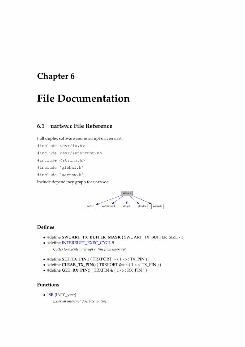
Include dependency graph for uartsw.c:
uartsw.c
avr/io.h avr/interrupt.h string.h global.h uartsw.h
Defines
• #define SWUART_TX_BUFFER_MASK ( SWUART_TX_BUFFER_SIZE - 1)• #define INTERRUPT_EXEC_CYCL 9
Cycles to execute interrupt rutine from interrupt.
• #define SET_TX_PIN() ( TRXPORT |= ( 1 << TX_PIN ) )• #define CLEAR_TX_PIN() ( TRXPORT &= ∼( 1 << TX_PIN ) )• #define GET_RX_PIN() ( TRXPIN & ( 1 << RX_PIN ) )
Functions
• ISR (INT0_vect)
External interrupt 0 service routine.
22 File Documentation
• ISR (TIMER0_COMP_VECT)
Timer0 interrupt service routine.
• ISR (TIMER2_COMP_VECT)
Timer2 interrupt service routine.
• void uartsw_init (void)
Function to initialize the software UART.
• void uartsw_putc (const unsigned char c)
Send a unsigned char.
• int uartsw_status (void)• void uartsw_setFunc (void(∗func)(uint8_t))
Sets the recieve function callback for the sw uart.
Variables
• static volatile unsigned char SWUART_TxBuf [SWUART_TX_BUFFER_SIZE]• static volatile unsigned char SWUART_TxHead• static volatile unsigned char SWUART_TxTail• volatile AsynchronousStatesRX_t stateRX
Holds the state of the UART.
• static volatile AsynchronousStatesTX_t stateTX
Holds the state of the UART.
• static volatile unsigned char SwUartTXData
Data to be transmitted.
• static volatile unsigned char SwUartTXBitCount
TX bit counter.
• volatile unsigned char SwUartRXData
Storage for received bits.
• static volatile unsigned char SwUartRXBitCount
RX bit counter.
• static void(∗ swuart_recvFunc )(uint8_t ch)
6.1.1 Detailed Description
UART software implementation using Timer0, Timer2 and external interrupt 0.
Note that the RX_PIN must be the external interrupt 0 pin on your AVR of choice. The TX_PINcan be chosen to be any suitable pin.
Hydrozoa V
6.1 uartsw.c File Reference 23
6.1.2 Function Documentation
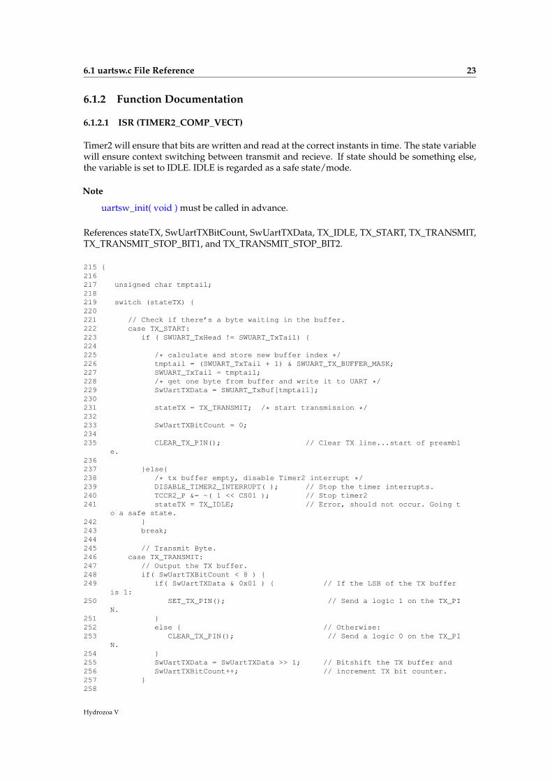
6.1.2.1 ISR (TIMER2_COMP_VECT)
Timer2 will ensure that bits are written and read at the correct instants in time. The state variablewill ensure context switching between transmit and recieve. If state should be something else,the variable is set to IDLE. IDLE is regarded as a safe state/mode.
Note
uartsw_init( void ) must be called in advance.
References stateTX, SwUartTXBitCount, SwUartTXData, TX_IDLE, TX_START, TX_TRANSMIT,TX_TRANSMIT_STOP_BIT1, and TX_TRANSMIT_STOP_BIT2.
215 {216217 unsigned char tmptail;218219 switch (stateTX) {220221 // Check if there’s a byte waiting in the buffer.222 case TX_START:223 if ( SWUART_TxHead != SWUART_TxTail) {224225 /* calculate and store new buffer index */226 tmptail = (SWUART_TxTail + 1) & SWUART_TX_BUFFER_MASK;227 SWUART_TxTail = tmptail;228 /* get one byte from buffer and write it to UART */229 SwUartTXData = SWUART_TxBuf[tmptail];230231 stateTX = TX_TRANSMIT; /* start transmission */232233 SwUartTXBitCount = 0;234235 CLEAR_TX_PIN(); // Clear TX line...start of preambl
e.236237 }else{238 /* tx buffer empty, disable Timer2 interrupt */239 DISABLE_TIMER2_INTERRUPT( ); // Stop the timer interrupts.240 TCCR2_P &= ~( 1 << CS01 ); // Stop timer2241 stateTX = TX_IDLE; // Error, should not occur. Going t
o a safe state.242 }243 break;244245 // Transmit Byte.246 case TX_TRANSMIT:247 // Output the TX buffer.248 if( SwUartTXBitCount < 8 ) {249 if( SwUartTXData & 0x01 ) { // If the LSB of the TX buffer
is 1:250 SET_TX_PIN(); // Send a logic 1 on the TX_PI
N.251 }252 else { // Otherwise:253 CLEAR_TX_PIN(); // Send a logic 0 on the TX_PI
N.254 }255 SwUartTXData = SwUartTXData >> 1; // Bitshift the TX buffer and256 SwUartTXBitCount++; // increment TX bit counter.257 }258
Hydrozoa V
24 File Documentation
259 //Send stop bit.260 else {261 SET_TX_PIN(); // Output a logic 1.262 stateTX = TX_TRANSMIT_STOP_BIT1;263 }264 break;265266 // Go to idle after stop bit was sent.267 case TX_TRANSMIT_STOP_BIT1:268 stateTX = TX_TRANSMIT_STOP_BIT2;269 break;270271 case TX_TRANSMIT_STOP_BIT2:272 stateTX = TX_START;273 break;274275 // Unknown state.276 default:277 stateTX = TX_IDLE; // Error, should not occur. Goin
g to a safe state.278 }279 }
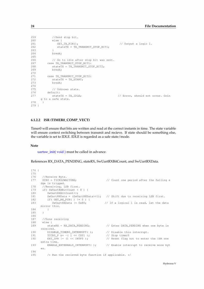
6.1.2.2 ISR (TIMER0_COMP_VECT)
Timer0 will ensure that bits are written and read at the correct instants in time. The state variablewill ensure context switching between transmit and recieve. If state should be something else,the variable is set to IDLE. IDLE is regarded as a safe state/mode.
Note
uartsw_init( void ) must be called in advance.
References RX_DATA_PENDING, stateRX, SwUartRXBitCount, and SwUartRXData.
174 {175176 //Receive Byte.177 OCR0 = TICKS2WAITONE; // Count one period after the falling e
dge is trigged.178 //Receiving, LSB first.179 if( SwUartRXBitCount < 8 ) {180 SwUartRXBitCount++;181 SwUartRXData = (SwUartRXData>>1); // Shift due to receiving LSB first.182 if( GET_RX_PIN( ) != 0 ) {183 SwUartRXData |= 0x80; // If a logical 1 is read, let the data
mirror this.184 }185 }186187 //Done receiving188 else {189 stateRX = RX_DATA_PENDING; // Enter DATA_PENDING when one byte is
received.190 DISABLE_TIMER0_INTERRUPT( ); // Disable this interrupt.191 TCCR0_P &= ~( 1 << CS01 ); // Stop timer0192 EXT_IFR |= (1 << INTF0 ); // Reset flag not to enter the ISR one
extra time.193 ENABLE_EXTERNAL0_INTERRUPT( ); // Enable interrupt to receive more byt
es.194195 /* Run the recieved byte function if applicable. */
Hydrozoa V
6.1 uartsw.c File Reference 25
196 if (swuart_recvFunc != NULL)197 swuart_recvFunc( SwUartRXData );198 }199 }
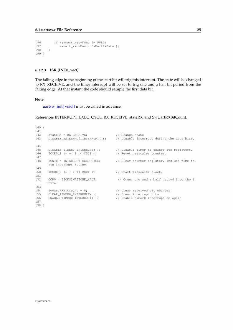
6.1.2.3 ISR (INT0_vect)
The falling edge in the beginning of the start bit will trig this interrupt. The state will be changedto RX_RECEIVE, and the timer interrupt will be set to trig one and a half bit period from thefalling edge. At that instant the code should sample the first data bit.
Note
uartsw_init( void ) must be called in advance.
References INTERRUPT_EXEC_CYCL, RX_RECEIVE, stateRX, and SwUartRXBitCount.
140 {141142 stateRX = RX_RECEIVE; // Change state143 DISABLE_EXTERNAL0_INTERRUPT( ); // Disable interrupt during the data bits.
144145 DISABLE_TIMER0_INTERRUPT( ); // Disable timer to change its registers.146 TCCR0_P &= ~( 1 << CS01 ); // Reset prescaler counter.147148 TCNT0 = INTERRUPT_EXEC_CYCL; // Clear counter register. Include time to
run interrupt rutine.149150 TCCR0_P |= ( 1 << CS01 ); // Start prescaler clock.151152 OCR0 = TICKS2WAITONE_HALF; // Count one and a half period into the f
uture.153154 SwUartRXBitCount = 0; // Clear received bit counter.155 CLEAR_TIMER0_INTERRUPT( ); // Clear interrupt bits156 ENABLE_TIMER0_INTERRUPT( ); // Enable timer0 interrupt on again157158 }
Hydrozoa V
Index
__AVR_ATmega128__jpegue, 14
AsynchronousStatesRX_tjpegue, 14
AsynchronousStatesTX_tjpegue, 14
bufUart_s, 20
Group_s, 17servos, 17size, 17speed, 17state, 17tol, 17
ISRuartsw.c, 23–25
jpegue__AVR_ATmega128__, 14AsynchronousStatesRX_t, 14AsynchronousStatesTX_t, 14RX_DATA_PENDING, 14RX_IDLE, 14RX_RECEIVE, 14TX_IDLE, 14TX_START, 14TX_TRANSMIT, 15TX_TRANSMIT_STOP_BIT1, 15TX_TRANSMIT_STOP_BIT2, 15uartsw_init, 15uartsw_putc, 16uartsw_status, 16
pfleury_uartuart1_getc, 9uart1_init, 9uart1_putc, 9uart1_puts, 9uart1_puts_p, 10UART_BAUD_SELECT, 9UART_BAUD_SELECT_DOUBLE_-
SPEED, 9
uart_getc, 10uart_init, 10uart_putc, 10uart_puts, 11uart_puts_p, 11uart_setFunc, 11uart_status, 11UART_TX_BUFFER_SIZE, 9
posServo_s, 19Uart_s, 20
putcUart_s, 20
RX_DATA_PENDINGjpegue, 14
RX_IDLEjpegue, 14
RX_RECEIVEjpegue, 14
Servo_s, 19pos, 19speed, 19target, 19uart, 19
servosGroup_s, 17
sizeGroup_s, 17
Software UART Library, 13speed
Group_s, 17Servo_s, 19
stateGroup_s, 17
statusUart_s, 20
targetServo_s, 19
tolGroup_s, 17
TX_IDLEjpegue, 14
INDEX 27
TX_STARTjpegue, 14
TX_TRANSMITjpegue, 15
TX_TRANSMIT_STOP_BIT1jpegue, 15
TX_TRANSMIT_STOP_BIT2jpegue, 15
uartServo_s, 19
UART Library, 7uart1_getc
pfleury_uart, 9uart1_init
pfleury_uart, 9uart1_putc
pfleury_uart, 9uart1_puts
pfleury_uart, 9uart1_puts_p
pfleury_uart, 10UART_BAUD_SELECT
pfleury_uart, 9UART_BAUD_SELECT_DOUBLE_SPEED
pfleury_uart, 9uart_getc
pfleury_uart, 10uart_init
pfleury_uart, 10uart_putc
pfleury_uart, 10uart_puts
pfleury_uart, 11uart_puts_p
pfleury_uart, 11Uart_s, 20
buf, 20pos, 20putc, 20status, 20
uart_setFuncpfleury_uart, 11
uart_statuspfleury_uart, 11
UART_TX_BUFFER_SIZEpfleury_uart, 9
uartsw.c, 21ISR, 23–25
uartsw_initjpegue, 15
uartsw_putcjpegue, 16
uartsw_status
jpegue, 16
Hydrozoa V

Acknowledgements
Thanks to the Institut de Robotica i Informatica Industrial [4] and Humanoid Lab Team [10]for making this all possible. Specials thanks to Guillem Alenya, Sergi Hernandez and Jose LuisRivero as mentors of the project. Finally a big thanks to the Generalitat of Catalunya [2] forfinancing the project as part of it’s Beques de Programari Lliure project [5].
IRI reports
This report is in the series of IRI technical reports.All IRI technical reports are available for download at the IRI websitehttp://www.iri.upc.edu.