Embed Size (px)
Citation preview
8/2/2019 115301-7474 IJMME-IJENS
http://slidepdf.com/reader/full/115301-7474-ijmme-ijens 1/10
International Journal of Mechanical & Mechatronics Engineering IJMME-IJENS Vol: 11 No: 01 16
115301-7474 IJMME-IJENS © February 2011 IJENS I J E N S
Design and Blade Optimization of Contra Rotation Double
Rotor Wind Turbine
Priyono Sutikno1, Deny Bayu Saepudin
2
1Institut Teknologi Bandung, Bandung, Indonesia, [email protected]
2Institut Teknologi Bandung, Bandung, Indonesia, [email protected]
Abstract - The Intelligent Wind turbine (IWT) has two stagesblades contra rotation. This kind of wind turbine hascharacteristic self regulated on the speed due to thedifference torque between two stages horizontal axis wind
turbine, than no need the pitch controller to control thespeed and cut off the wind turbine due to the high wind
speed.The research of IWT is designed first by optimize severalimportant design parameters, as a blade section profile and
the multiplier factor of the angle of attack. The designparameter results are the NACA 6412 is selected as the
optimum blade section profile and the optimum value of angle of attack multiplier factor is 0.5. The designed IWThas 3 blades for each front and rear rotor. The researchintelligent wind turbine has 600 mm front diameter and 600
mm rear blade diameter. The characteristics of IWT weresimulated by using Computational Fluid Dynamic (CFD)
software, demonstrated the non entrainment of the contrarotation, each blades should have the same produced torque.
Index Terms – Intelligent Wind Turbine, NumericalSimulation, Contra rotation Wind Turbine
I. INTRODUCTIONThe conventional wind turbines with large sized wind
rotor generate high output in the moderately strong wind.The output of the small sized wind rotor is low such awind rotor is suitable for weak wind. That is, the size of
the wind rotor must be appropriately selected inconformity with potential wind circumstances. Besides, ingeneral the wind turbines are equipped with the brake andor the pitch control mechanisms, to control the speed dueto the abnormal rotation and the overload generated at thestronger wind, and to keep the rotation of generator. Inthat sense, some studies present a good review of various
invented the superior wind turbine generator, T.
Kanemoto [1] has invented Intelligent Wind TurbineGenerator (IWTG) composed of the large sized front wind
rotor, the small sized rear wind rotor and the peculiargenerator with inner and the outer rotational armatures, asthe rotational speeds of the tandem wind rotor areadjusted pretty well in cooperation with the two armatures
of the generator in response to the wind speed. The IWTGmodel is composed of tandem wind rotor using the flatblades, and demonstrated the fundamentally superior
operation of the tandem wind rotor. In this paper, theeffect of the blade profiles using NACA profiles on theturbine using numerical simulation on the turbineperformances are investigated to optimized the rotor
profiles.
Nomenclature A Area
a Axial induction factora’ Radial Induction factor B Number of blade
C D Drag coefficient
C L Lift coefficient
c Chord length
C p Power Coefficient D Diameter
F x Axial Force
g Acceleration of gravity L Lift forceP Power
p pressureQ correction factorr local radius element rotor
Re Reynolds number
R RadiusT Torsi
T ∆ Thrust
V o Absolute Velocityw Relative velocityu Tangential velocity
x Local speed ratio
α angle of attack (AOA) β stagger anglee Ratio coefficient Lift and Dragγ pitch angelη Efficiency λ Tip speed ratio ρ density
φ angle of attack relative
σ SolidityΩ Angular velocity
II. OPERATION OF TANDEM WIND ROTORSIn the IWTG both wind rotors start to rotate at low
wind speed, namely cut in wind speed, but the rear wind
rotor counter rotates against the front wind rotor. Theincrease of the wind speed make the both rotationalspeeds increase, and the rotational speed of rear wind
rotor becomes faster than that of the front wind rotorbecause of its small size. The rear wind rotor reaches themaximum rotational speed at rated wind speed. With
more increment of the wind speed, the rear wind rotordecelerates gradually and begins to rotate at the samedirection of the front wind rotor so as to coincide with
8/2/2019 115301-7474 IJMME-IJENS
http://slidepdf.com/reader/full/115301-7474-ijmme-ijens 2/10
International Journal of Mechanical & Mechatronics Engineering IJMME-IJENS Vol: 11 No: 01 17
115301-7474 IJMME-IJENS © February 2011 IJENS I J E N S
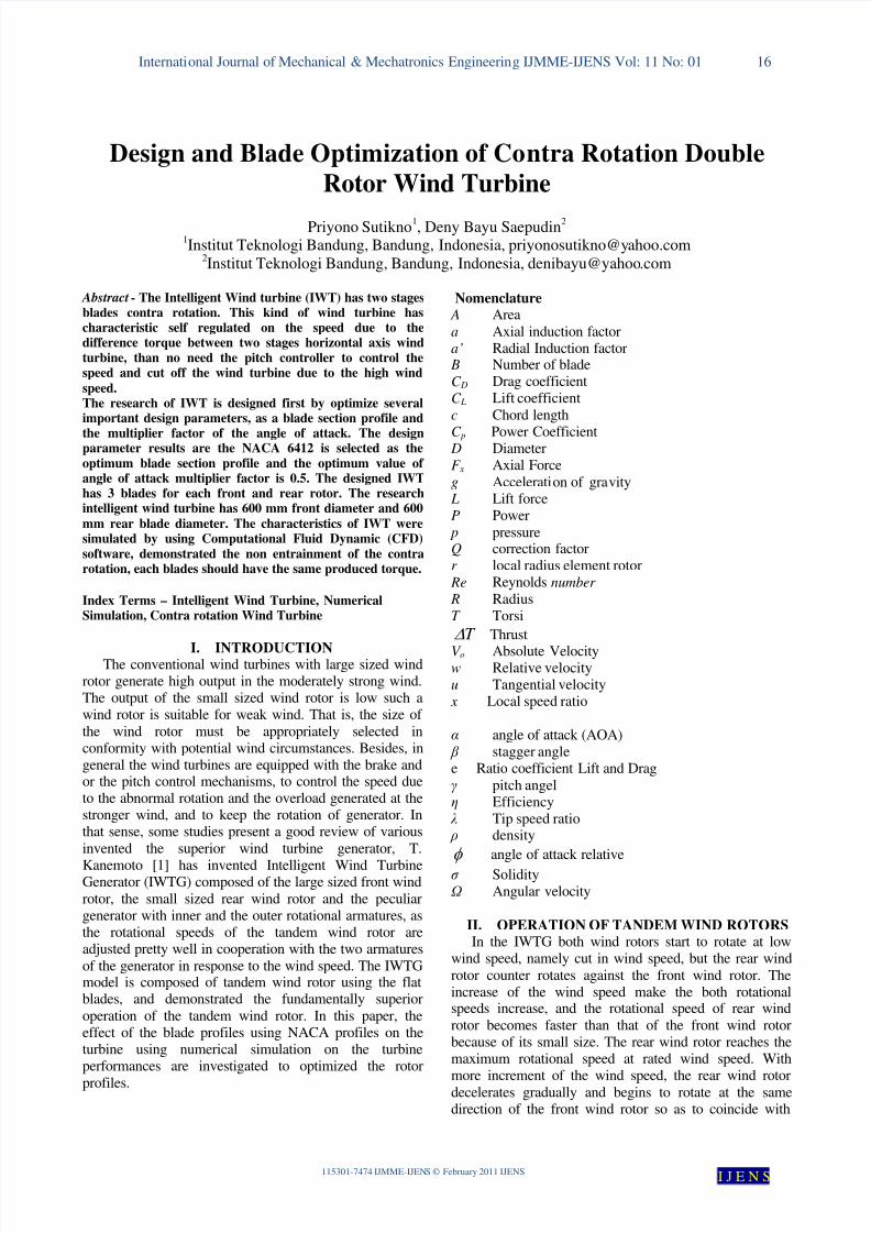
larger rotational torque of front wind rotor. Suchbehaviour of rear wind rotor is induced from the reasonwhy the small sizes wind rotor must work as the blowingmode against the attacking wind because the wind rotor
turbine mode can \not generate adequately the rotationaltorque corresponding to the front wind rotor. The
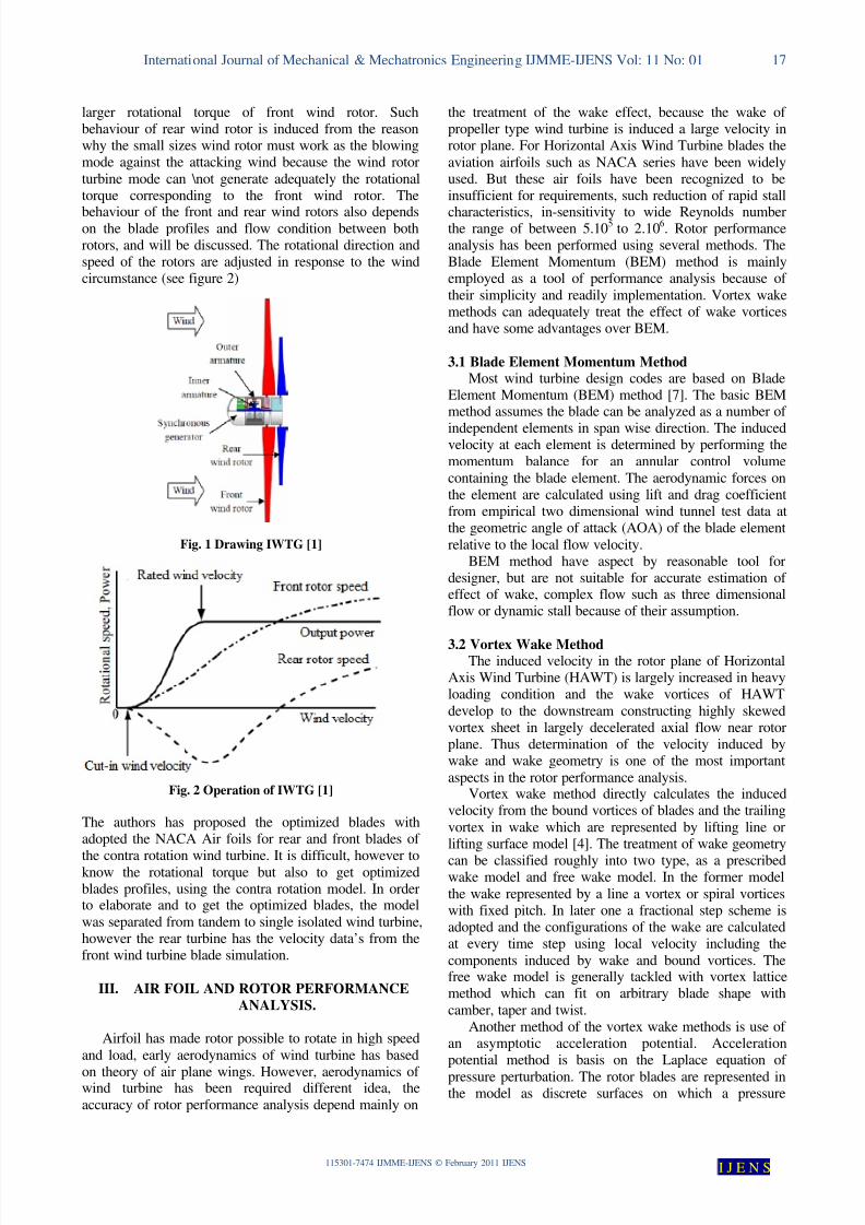
behaviour of the front and rear wind rotors also dependson the blade profiles and flow condition between bothrotors, and will be discussed. The rotational direction andspeed of the rotors are adjusted in response to the windcircumstance (see figure 2)
Fig. 1 Drawing IWTG [1]
Fig. 2 Operation of IWTG [1]
The authors has proposed the optimized blades withadopted the NACA Air foils for rear and front blades of
the contra rotation wind turbine. It is difficult, however toknow the rotational torque but also to get optimizedblades profiles, using the contra rotation model. In orderto elaborate and to get the optimized blades, the model
was separated from tandem to single isolated wind turbine,however the rear turbine has the velocity data’s from thefront wind turbine blade simulation.
III. AIR FOIL AND ROTOR PERFORMANCE
ANALYSIS.
Airfoil has made rotor possible to rotate in high speed
and load, early aerodynamics of wind turbine has based
on theory of air plane wings. However, aerodynamics of wind turbine has been required different idea, the
accuracy of rotor performance analysis depend mainly on
the treatment of the wake effect, because the wake of propeller type wind turbine is induced a large velocity inrotor plane. For Horizontal Axis Wind Turbine blades the
aviation airfoils such as NACA series have been widelyused. But these air foils have been recognized to beinsufficient for requirements, such reduction of rapid stall
characteristics, in-sensitivity to wide Reynolds numberthe range of between 5.10
5to 2.10
6. Rotor performance
analysis has been performed using several methods. TheBlade Element Momentum (BEM) method is mainlyemployed as a tool of performance analysis because of
their simplicity and readily implementation. Vortex wakemethods can adequately treat the effect of wake vorticesand have some advantages over BEM.
3.1 Blade Element Momentum MethodMost wind turbine design codes are based on Blade
Element Momentum (BEM) method [7]. The basic BEMmethod assumes the blade can be analyzed as a number of
independent elements in span wise direction. The inducedvelocity at each element is determined by performing themomentum balance for an annular control volume
containing the blade element. The aerodynamic forces onthe element are calculated using lift and drag coefficientfrom empirical two dimensional wind tunnel test data atthe geometric angle of attack (AOA) of the blade element
relative to the local flow velocity.BEM method have aspect by reasonable tool for
designer, but are not suitable for accurate estimation of effect of wake, complex flow such as three dimensionalflow or dynamic stall because of their assumption.
3.2 Vortex Wake MethodThe induced velocity in the rotor plane of Horizontal
Axis Wind Turbine (HAWT) is largely increased in heavyloading condition and the wake vortices of HAWT
develop to the downstream constructing highly skewedvortex sheet in largely decelerated axial flow near rotorplane. Thus determination of the velocity induced bywake and wake geometry is one of the most important
aspects in the rotor performance analysis.Vortex wake method directly calculates the induced
velocity from the bound vortices of blades and the trailing
vortex in wake which are represented by lifting line orlifting surface model [4]. The treatment of wake geometry
can be classified roughly into two type, as a prescribedwake model and free wake model. In the former model
the wake represented by a line a vortex or spiral vorticeswith fixed pitch. In later one a fractional step scheme isadopted and the configurations of the wake are calculatedat every time step using local velocity including the
components induced by wake and bound vortices. Thefree wake model is generally tackled with vortex latticemethod which can fit on arbitrary blade shape with
camber, taper and twist.Another method of the vortex wake methods is use of
an asymptotic acceleration potential. Accelerationpotential method is basis on the Laplace equation of
pressure perturbation. The rotor blades are represented inthe model as discrete surfaces on which a pressure
8/2/2019 115301-7474 IJMME-IJENS
http://slidepdf.com/reader/full/115301-7474-ijmme-ijens 3/10
International Journal of Mechanical & Mechatronics Engineering IJMME-IJENS Vol: 11 No: 01 18
115301-7474 IJMME-IJENS © February 2011 IJENS I J E N S
discontinuity is present. The model implies the presenceof span wise and chord wise pressure distributions, whichare composed of analytical asymptotic solution forLaplace equation. More elaborate model makes it possible
to calculate the dynamics load caused by dynamic inflowand yawed inflow situation [5].
3,3 Computational Fluid DynamicRecent development of the computational fluid
dynamics (CFD) allows us to simulate overall flowaround HAWT including tower and nacelle. In 1999
Duque et al. [6] calculated aerodynamics of HAWT usingRANS model and overset grids to facilitate the simulationof flow about complex configuration. Recently, someCFD’s codes actively are developed of CFD analysis of
rotor flow by three dimensional Navier Stokes code.Though the state of the art CFD is needed
considerable computer power and validation for NavierStokes model, CFD has potential advantage for detailed
understanding of aerodynamic of the HAWT.
IV. OPTIMAL ROTOR BLADE
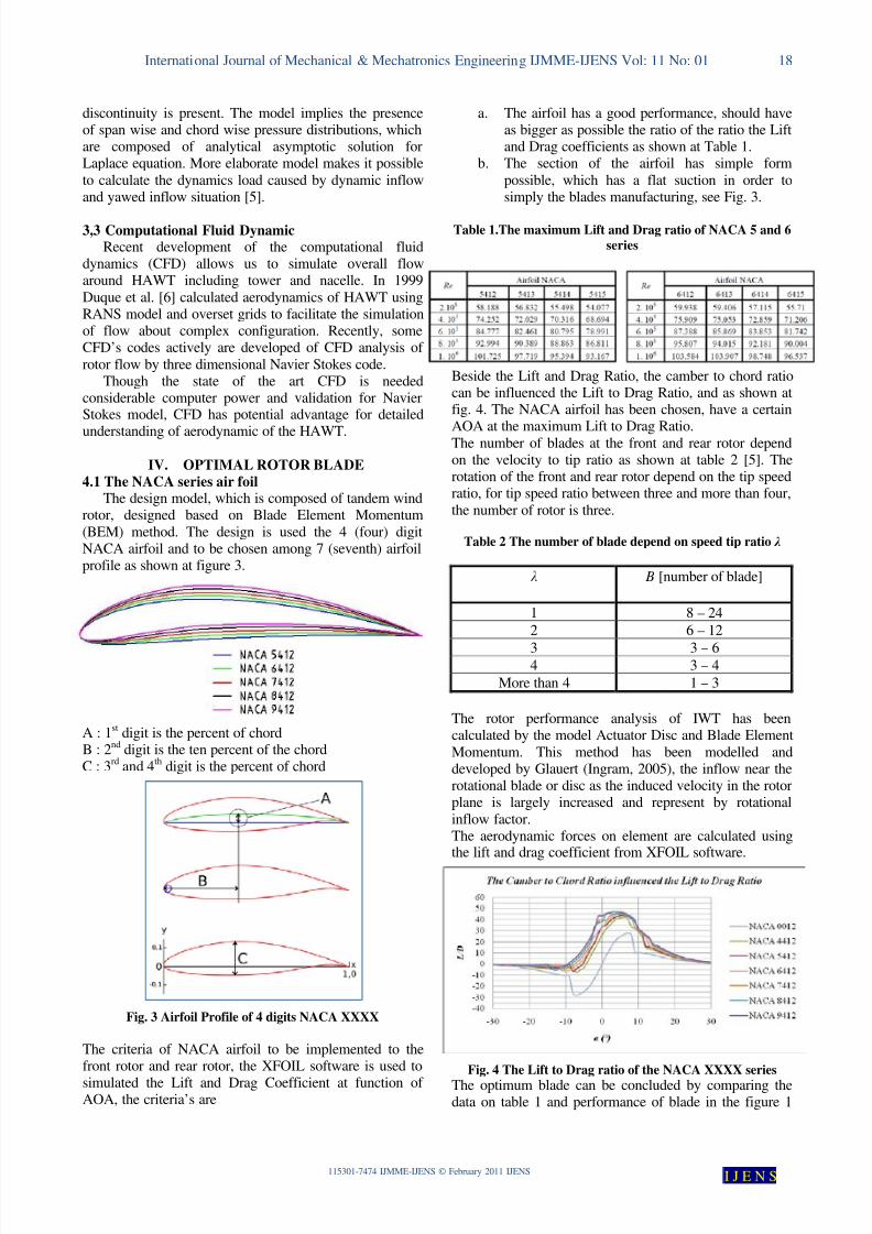
4.1 The NACA series air foilThe design model, which is composed of tandem wind
rotor, designed based on Blade Element Momentum
(BEM) method. The design is used the 4 (four) digitNACA airfoil and to be chosen among 7 (seventh) airfoilprofile as shown at figure 3.
A : 1st
digit is the percent of chordB : 2
nddigit is the ten percent of the chord
C : 3rd
and 4th
digit is the percent of chord
Fig. 3 Airfoil Profile of 4 digits NACA XXXX
The criteria of NACA airfoil to be implemented to thefront rotor and rear rotor, the XFOIL software is used to
simulated the Lift and Drag Coefficient at function of AOA, the criteria’s are
a. The airfoil has a good performance, should haveas bigger as possible the ratio of the ratio the Liftand Drag coefficients as shown at Table 1.
b. The section of the airfoil has simple form
possible, which has a flat suction in order tosimply the blades manufacturing, see Fig. 3.
Table 1.The maximum Lift and Drag ratio of NACA 5 and 6
series
Beside the Lift and Drag Ratio, the camber to chord ratiocan be influenced the Lift to Drag Ratio, and as shown atfig. 4. The NACA airfoil has been chosen, have a certain
AOA at the maximum Lift to Drag Ratio.The number of blades at the front and rear rotor dependon the velocity to tip ratio as shown at table 2 [5]. Therotation of the front and rear rotor depend on the tip speedratio, for tip speed ratio between three and more than four,
the number of rotor is three.
Table 2 The number of blade depend on speed tip ratio λ
λ B [number of blade]
1 8 – 24
2 6 – 12
3 3 – 64 3 – 4
More than 4 1 – 3
The rotor performance analysis of IWT has beencalculated by the model Actuator Disc and Blade Element
Momentum. This method has been modelled anddeveloped by Glauert (Ingram, 2005), the inflow near therotational blade or disc as the induced velocity in the rotorplane is largely increased and represent by rotational
inflow factor.The aerodynamic forces on element are calculated usingthe lift and drag coefficient from XFOIL software.
Fig. 4 The Lift to Drag ratio of the NACA XXXX series
The optimum blade can be concluded by comparing thedata on table 1 and performance of blade in the figure 1
8/2/2019 115301-7474 IJMME-IJENS
http://slidepdf.com/reader/full/115301-7474-ijmme-ijens 4/10
International Journal of Mechanical & Mechatronics Engineering IJMME-IJENS Vol: 11 No: 01 19
115301-7474 IJMME-IJENS © February 2011 IJENS I J E N S
and 4 with respect to the criterion above, the chosen bladehas thickness to chord ratio of 12%, the camber to chordratio is 6% and the air foil NACA 6412 is chosen asairfoil for front and rear rotor.
4.2 Optimal rotor blade using GLAUERT-PRANDTL-
XU model.The calculation is based on the Blade Element
Momentum (BEM) method, this method is suitable forengineering development and there are two kinds of categories: fixed pitch and variables pitch rotor blade. The
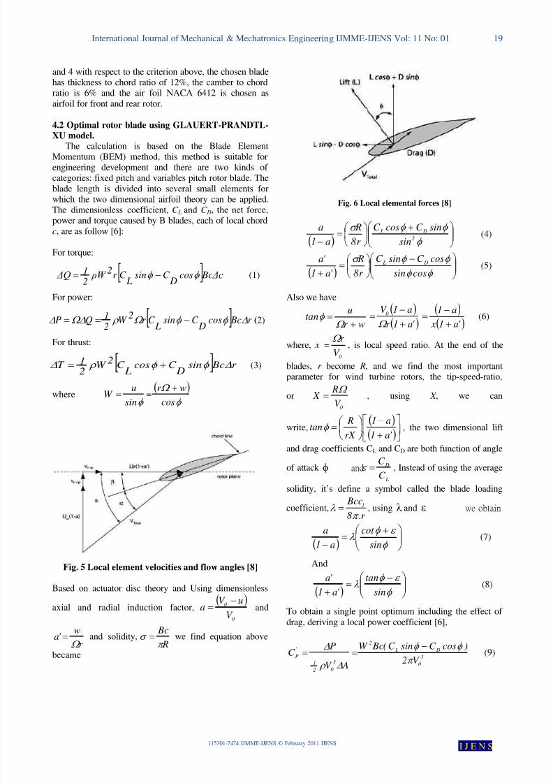
blade length is divided into several small elements forwhich the two dimensional airfoil theory can be applied.The dimensionless coefficient, C L and C D, the net force,power and torque caused by B blades, each of local chord
c, are as follow [6]:
For torque:
[ ] Bc Δccos DC sin LC r 2 ρW 21 ΔQ φ φ −= (1)
For power:
[ ] r Bccos D
C sin L
C r 2
W 21QP ∆φ φ Ω ρ Ω∆∆ −== (2)
For thrust:
[ ] r Bcsin DC cos
LC
2W
2
1T ∆φ φ ρ ∆ += (3)
whereφ sin
uW = =
( )φ
Ω
cos
wr +
Fig. 5 Local element velocities and flow angles [8]
Based on actuator disc theory and Using dimensionless
axial and radial induction factor,( )
0
0
V
uV a
−= and
r
w' a
Ω = and solidity,
R
Bc
π σ = we find equation above
became
Fig. 6 Local elemental forces [8]
( )
+
=
− φ
φ φ σ 2
D L
sin
sinC cosC
r 8
R
a1
a (4)
( )
−
=
+ φ φ
φ φ σ
cossin
cosC sinC
r 8
R
' a1
' a D L (5)
Also we have
wr
utan
+=Ω
φ ( )( )' a1r
a1V 0
+
−=Ω
( )( )' a1 x
a1
+
−= (6)
where, x =0
V
r Ω , is local speed ratio. At the end of the
blades, r become R, and we find the most importantparameter for wind turbine rotors, the tip-speed-ratio,
or0V
R X
Ω = , using X , we can
write,( )( )
+
−
=
' a1
a1
rX
Rtanφ , the two dimensional lift
and drag coefficients CL and CD are both function of angle
of attack φ and
L
D
C
C =ε , Instead of using the average
solidity, it’s define a symbol called the blade loading
coefficient,r .8
Bccl
π λ = , using λ and ε we obtain
( )
+=
−φ
ε φ λ
sin
cot
a1
a (7)
And
( )
−=
+ φ
ε φ λ
sin
tan
' a1
' a(8)
To obtain a single point optimum including the effect of
drag, deriving a local power coefficient [6],
3
0
D L
2
3
02
1
'
PV 2
)cosC sinC ( BcW
AV
PC
π
φ φ
∆ ρ
∆ −== (9)
8/2/2019 115301-7474 IJMME-IJENS
http://slidepdf.com/reader/full/115301-7474-ijmme-ijens 5/10
International Journal of Mechanical & Mechatronics Engineering IJMME-IJENS Vol: 11 No: 01 20
115301-7474 IJMME-IJENS © February 2011 IJENS I J E N S
where,
[ ] dr BccosC sinC Ωr ρV ΩdQdP D L
2
total2
1 φ φ −==
and dA =2 π dr by using :
( ) ( )222222
totala1r a1U V ′++−= ∞ Ω and equation 6, then
equation 9 can be write
( ) ( ) ( )φ φ cosεφsin x λ4cot 1a1C 22
p−++−=′
(10)
Then, eliminating λ using equation 7 and expanding 1/(cot
φ + ε) in a Taylor’s series of two terms, there results
( )( )( )φ ε ε φ tan1tana1 xa4C p
+−−=′ (11)
Since the optimum value of a is founded to be quite
insensitive to changes in ε, this implies that pC′ decreases
monotonically as ε increases. By defining a local Froude
efficiency (Eq. 12), we can relate the performance of each
blade element to the ideal value of unity [6].
pF C 16
27 ′
=η (12)
The correction factor for total losses can actually be quitewell represented by Prandtl and Xu represent the tiplosses and hub losses, the equation is quite simple but can
give the good matched on HWAT (Horizontal Axis WindTurbine) [10], the Prandtl tip correction factor is
( ) 12cos exp 7tip tip tipQ f if f
π
−= − ≤
1 7tip tip
Q if f = >(13)
( )2 sin
tip
B R r f
r φ
−=
And for hub correction factor can be written as
( ) 12cos exp 7
hub hub hubQ f if f
π
−= − ≤
1 7hub hubQ if f = >
(14)
( )2 sin
hub
hub
hub
B r R f
R φ
−=
Early 2001, Xu proposed the correction factor on hublosses by using the Prandtl correction factor as writtenabove and the Xu correction factor for hub can be written
as
( )( )0,85
0,5 0,5 0, 7 1new
tip tipr Q Q if R
= + ≤ ≤(15)
( ) / 0,71
1 0.70,7
tipr Rnew
tip
r Qr Q if
R R
=−
= − <
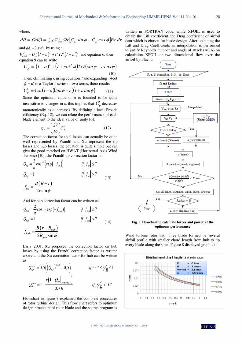
Flowchart in figure 7 explained the complete proceduresof rotor turbine design. This flow chart refers to optimumdesign procedure of rotor blade and the source program is
written in FORTRAN code, while XFOIL is used toobtain the Lift coefficient and Drag coefficient of airfoildata which is chosen for blade design. After obtaining theLift and Drag Coefficients an interpolation is performed
to justify Reynolds number and angle of attack (AOA) oncalculation XFOIL or two dimensional flow over the
airfoil by Fluent.
Fig. 7 Flowchart to calculate forces and power at the
optimum performance
Wind turbine rotor with three blade formed by several
airfoil profile with smaller chord length from hub to tipevery blade along the span. Figure 8 displayed graphic of
8/2/2019 115301-7474 IJMME-IJENS
http://slidepdf.com/reader/full/115301-7474-ijmme-ijens 6/10
International Journal of Mechanical & Mechatronics Engineering IJMME-IJENS Vol: 11 No: 01 21
115301-7474 IJMME-IJENS © February 2011 IJENS I J E N S
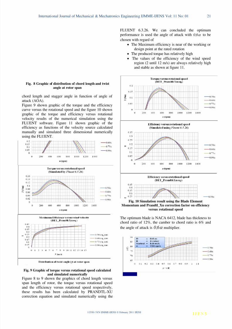
Fig. 8 Graphic of distribution of chord length and twistangle at rotor span
chord length and stagger angle in function of angle of
attack (AOA).Figure 9 shown graphic of the torque and the efficiencycurve versus the rotational speed and the figure 10 shown
graphic of the torque and efficiency versus rotationalvelocity results of the numerical simulation using theFLUENT software. Figure 11 shown graphic of theefficiency as functions of the velocity source calculated
manually and simulated three dimensional numericallyusing the FLUENT.
Fig. 9 Graphic of torque versus rotational speed calculatedand simulated numerically
Figure 8 to 9 shown the graphics of chord length versusspan length of rotor, the torque versus rotational speed
and the efficiency versus rotational speed respectively,these results has been calculated by PRANDTL-XUcorrection equation and simulated numerically using the
FLUENT 6.3.26. We can concluded the optimum
performance is used the angle of attack with α 6 ,0 to be
chosen with regard of
• The Maximum efficiency is near of the working or
design point at the rated rotation
• The produced torque has relatively high
• The values of the efficiency of the wind speedregion (2 until 12 m/s) are always relatively high
and stable as shown at figure 11.
Fig. 10 Simulation result using the Blade ElementMomentum and Prandtl_Xu correction factor on efficiency
versus rotational speed
The optimum blade is NACA 6412, blade has thickness tochord ratio of 12%, the camber to chord ratio is 6% and
the angle of attack is α 6 ,0 multiplier.
8/2/2019 115301-7474 IJMME-IJENS
http://slidepdf.com/reader/full/115301-7474-ijmme-ijens 7/10
International Journal of Mechanical & Mechatronics Engineering IJMME-IJENS Vol: 11 No: 01 22
115301-7474 IJMME-IJENS © February 2011 IJENS I J E N S
Fig. 11 The efficiency versus wind speed
V. DESIGN AND SIMULATION OF THE IWT
5.1 Design Procedures for Wind Turbine Rotor
Flowchart in figure 7 explained the completeprocedures of rotor turbine design. This flowchart refersto optimum design procedure of rotor blade, and thesource program is written in EXCELL code, while theXFOIL or FLUENT software is used to obtain lift
coefficient (CL) and drag coefficient (CD) of airfoil datawhich is chosen for the blade design. After obtaining thelift coefficient (CL) and drag coefficient (CD), aninterpolation is performed to justify Reynolds number and
angle of attack on calculation.
5.2 Simulation Procedures for Intelligent Wind
Turbine Front and Rear Rotors
The simulation of Intelligent Wind Turbine front andrear rotors are using computational fluid dynamic (CFD)method through Fluent software. The simulation process
consists in two parts, the two dimension model and threedimension models. Two dimension model is usingFLUENT DDP to calculate lift coefficient (CL), dragcoefficient (CD), pressure coefficient and flow
characteristic through airfoil profile in two dimension,while Fluent 3D is used to calculate force componentswhich rotor produced and flow characteristic in threedimension, especially flow behind the rotor which shown
velocity decrease and wind energy, turbulence, and wake.The two dimension simulation proposed to obtain airfoil
characteristics which will be used in blade design withangle of attack variation and Reynolds number variations,then served as an input on blade design by usinginterpolation. The airfoil profile has been calculated andsimulated at section 4.
Two dimension simulation process is completed byGambit meshing around 66.000 cells and iteration usingFLUENT 2DDP with assumption of compressible flowand coupled solver was used including energy calculation
using absolute velocity formulation in steady condition.These assumptions are requisite in order to obtainaccurate current model on airfoil surface by showing
turbulence phenomenon, flow separation, boundary layer,
and reversed flow. This flow phenomenon is their natural
flow characteristic, where the decreasing of whole airfoilperformance and rotor efficiency in extreme situation [9].
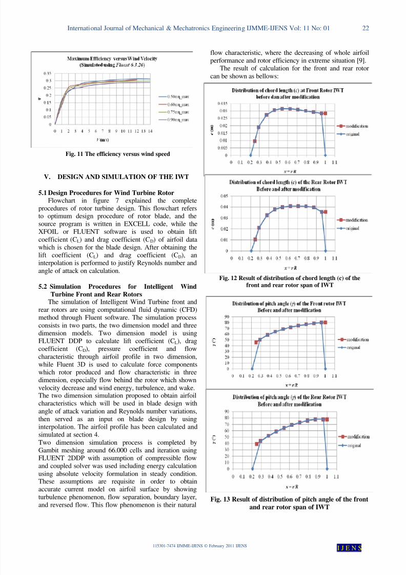
The result of calculation for the front and rear rotor
can be shown as bellows:
Fig. 12 Result of distribution of chord length (c) of thefront and rear rotor span of IWT
Fig. 13 Result of distribution of pitch angle of the front
and rear rotor span of IWT
8/2/2019 115301-7474 IJMME-IJENS
http://slidepdf.com/reader/full/115301-7474-ijmme-ijens 8/10
International Journal of Mechanical & Mechatronics Engineering IJMME-IJENS Vol: 11 No: 01 23
115301-7474 IJMME-IJENS © February 2011 IJENS I J E N S
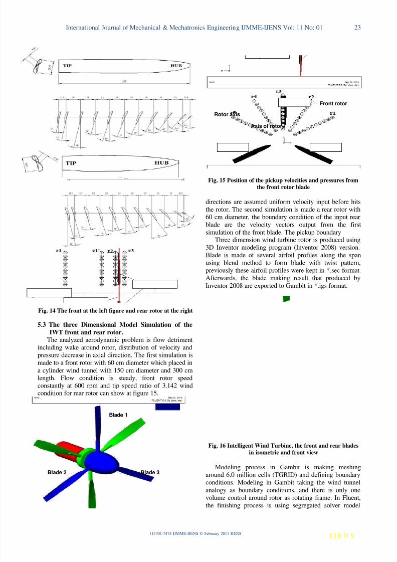
Fig. 14 The front at the left figure and rear rotor at the right
5.3 The three Dimensional Model Simulation of the
IWT front and rear rotor.The analyzed aerodynamic problem is flow detriment
including wake around rotor, distribution of velocity andpressure decrease in axial direction. The first simulation ismade to a front rotor with 60 cm diameter which placed in
a cylinder wind tunnel with 150 cm diameter and 300 cmlength. Flow condition is steady, front rotor speedconstantly at 600 rpm and tip speed ratio of 3.142 wind
condition for rear rotor can show at figure 15.
Fig. 15 Position of the pickup velocities and pressures fromthe front rotor blade
directions are assumed uniform velocity input before hitsthe rotor. The second simulation is made a rear rotor with60 cm diameter, the boundary condition of the input rearblade are the velocity vectors output from the first
simulation of the front blade. The pickup boundaryThree dimension wind turbine rotor is produced using
3D Inventor modeling program (Inventor 2008) version.
Blade is made of several airfoil profiles along the spanusing blend method to form blade with twist pattern,previously these airfoil profiles were kept in *.sec format.Afterwards, the blade making result that produced by
Inventor 2008 are exported to Gambit in *.igs format.
Fig. 16 Intelligent Wind Turbine, the front and rear bladesin isometric and front view
Modeling process in Gambit is making meshingaround 6.0 million cells (TGRID) and defining boundaryconditions. Modeling in Gambit taking the wind tunnel
analogy as boundary conditions, and there is only onevolume control around rotor as rotating frame. In Fluent,the finishing process is using segregated solver model
Front rotor
Axis of rotor
Rotor axis
Blade 3Blade 2
Blade 1
8/2/2019 115301-7474 IJMME-IJENS
http://slidepdf.com/reader/full/115301-7474-ijmme-ijens 9/10
International Journal of Mechanical & Mechatronics Engineering IJMME-IJENS Vol: 11 No: 01 24
115301-7474 IJMME-IJENS © February 2011 IJENS I J E N S
with relative velocity formulation or multiple referenceframes (MRF) model and steady conditions. It isimportant to do the relative velocity formulation becausethe volume control that used is rotating frame (non
inertia) [2], in order to analyze relative velocity impact toa rotor and exposed current flow behind the rotor (wake)
[9]. The expected result in 3D simulation is to get far flowaround rotor, not just only at the rotor surface. Theapplied viscous model is the same model that applied in2D simulation which is viscous k-ε model [8], [10].
VI. RESULT AND DISCUSSION
Two dimension and three dimension rotor turbine areanalysis using optimum blade design and calculated withBET PRANDTL-XU methods or designed and simulated
by 3D Fluent indicates a good results and have samesimilitude. If we compare both analyses result by fluentand by BET PRANDTL-XU methods, it turned out that
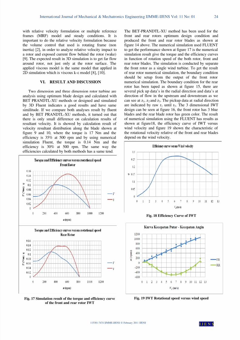
there is only small difference on calculation results of resultant velocity. It is showed by calculation result of velocity resultant distribution along the blade shown atfigure 9 and 10, where the torque is 17 Nm and the
efficiency is 35% at 500 rpm and by using numericalsimulation Fluent, the torque is 0.14 Nm and theefficiency is 30% at 500 rpm. The same way theefficiencies calculated by both methods has a same tend.
Fig. 17 Simulation result of the torque and efficiency curveof the front and rear rotor IWT
The BET-PRANDTL-XU method has been used for thefront and rear rotors optimum design condition andproduced the front and rear rotor blades as shown atfigure 14 above. The numerical simulation used FLUENT
to get the performance shown at figure 17 is the numericalsimulation result give the torque and the efficiency curves
in function of rotation speed of the both rotor, front andrear rotor blades. The simulation is conducted by separatethe front rotor as a single wind turbine. To get the resultof rear rotor numerical simulation, the boundary conditionshould be setup from the output of the front rotor
numerical simulation. The boundary condition for the rearrotor has been taped as shown at figure 15, there areseveral pick up data’s in the radial direction and data’s atdirection of flow in the upstream and downstream as we
can see at z1, z2 and z3. The pickup data at radial directionare indicated by raw r1 until r5. The 3 dimensional IWTdesign can be seen at figure 16, the front rotor has 3 blueblades and the rear blade rotor has green color. The result
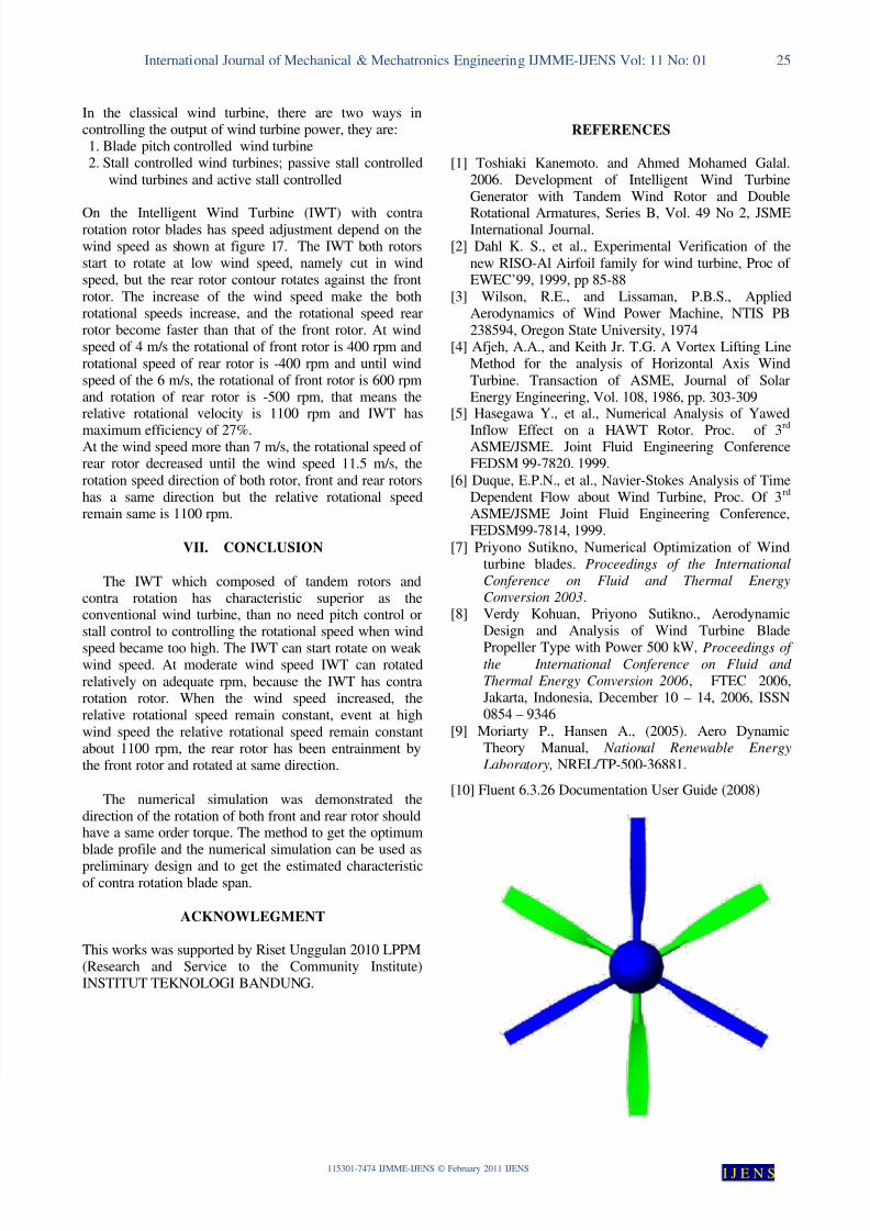
of numerical simulation using the FLUENT has results asshown at figure18, the efficiency curve of IWT versuswind velocity and figure 19 shown the characteristic of
the rotational velocity relative of the front and rear bladesdepend on the wind velocity.
Fig. 18 Efficiency Curve of IWT
Fig. 19 IWT Rotational speed versus wind speed
8/2/2019 115301-7474 IJMME-IJENS
http://slidepdf.com/reader/full/115301-7474-ijmme-ijens 10/10
International Journal of Mechanical & Mechatronics Engineering IJMME-IJENS Vol: 11 No: 01 25
115301-7474 IJMME-IJENS © February 2011 IJENS I J E N S
In the classical wind turbine, there are two ways incontrolling the output of wind turbine power, they are:1. Blade pitch controlled wind turbine2. Stall controlled wind turbines; passive stall controlled
wind turbines and active stall controlled
On the Intelligent Wind Turbine (IWT) with contrarotation rotor blades has speed adjustment depend on thewind speed as shown at figure 17. The IWT both rotorsstart to rotate at low wind speed, namely cut in windspeed, but the rear rotor contour rotates against the front
rotor. The increase of the wind speed make the bothrotational speeds increase, and the rotational speed rearrotor become faster than that of the front rotor. At windspeed of 4 m/s the rotational of front rotor is 400 rpm and
rotational speed of rear rotor is -400 rpm and until windspeed of the 6 m/s, the rotational of front rotor is 600 rpmand rotation of rear rotor is -500 rpm, that means therelative rotational velocity is 1100 rpm and IWT has
maximum efficiency of 27%.At the wind speed more than 7 m/s, the rotational speed of rear rotor decreased until the wind speed 11.5 m/s, the
rotation speed direction of both rotor, front and rear rotorshas a same direction but the relative rotational speedremain same is 1100 rpm.
VII. CONCLUSION
The IWT which composed of tandem rotors andcontra rotation has characteristic superior as theconventional wind turbine, than no need pitch control orstall control to controlling the rotational speed when wind
speed became too high. The IWT can start rotate on weak wind speed. At moderate wind speed IWT can rotated
relatively on adequate rpm, because the IWT has contrarotation rotor. When the wind speed increased, therelative rotational speed remain constant, event at high
wind speed the relative rotational speed remain constantabout 1100 rpm, the rear rotor has been entrainment bythe front rotor and rotated at same direction.
The numerical simulation was demonstrated thedirection of the rotation of both front and rear rotor shouldhave a same order torque. The method to get the optimumblade profile and the numerical simulation can be used as
preliminary design and to get the estimated characteristicof contra rotation blade span.
ACKNOWLEGMENT
This works was supported by Riset Unggulan 2010 LPPM(Research and Service to the Community Institute)INSTITUT TEKNOLOGI BANDUNG.
REFERENCES
[1] Toshiaki Kanemoto. and Ahmed Mohamed Galal.2006. Development of Intelligent Wind TurbineGenerator with Tandem Wind Rotor and Double
Rotational Armatures, Series B, Vol. 49 No 2, JSMEInternational Journal.
[2] Dahl K. S., et al., Experimental Verification of the
new RISO-Al Airfoil family for wind turbine, Proc of EWEC’99, 1999, pp 85-88
[3] Wilson, R.E., and Lissaman, P.B.S., AppliedAerodynamics of Wind Power Machine, NTIS PB
238594, Oregon State University, 1974[4] Afjeh, A.A., and Keith Jr. T.G. A Vortex Lifting Line
Method for the analysis of Horizontal Axis Wind
Turbine. Transaction of ASME, Journal of SolarEnergy Engineering, Vol. 108, 1986, pp. 303-309
[5] Hasegawa Y., et al., Numerical Analysis of Yawed
Inflow Effect on a HAWT Rotor. Proc. of 3rd
ASME/JSME. Joint Fluid Engineering ConferenceFEDSM 99-7820. 1999.
[6] Duque, E.P.N., et al., Navier-Stokes Analysis of TimeDependent Flow about Wind Turbine, Proc. Of 3
rd
ASME/JSME Joint Fluid Engineering Conference,FEDSM99-7814, 1999.
[7] Priyono Sutikno, Numerical Optimization of Windturbine blades. Proceedings of the International
Conference on Fluid and Thermal EnergyConversion 2003.
[8] Verdy Kohuan, Priyono Sutikno., AerodynamicDesign and Analysis of Wind Turbine Blade
Propeller Type with Power 500 kW, Proceedings of the International Conference on Fluid and
Thermal Energy Conversion 2006 , FTEC 2006,Jakarta, Indonesia, December 10 – 14, 2006, ISSN0854 – 9346
[9] Moriarty P., Hansen A., (2005). Aero DynamicTheory Manual, National Renewable Energy
Laboratory, NREL/TP-500-36881.
[10] Fluent 6.3.26 Documentation User Guide (2008)


![IJENS-RPG [IJENS Researchers Promotion Group] … · IJENS-RPG [IJENS Researchers Promotion Group] ... [IJENS Researchers Promotion Group] ID: ... 1 Hardeep Singh, Jai](https://img.pdfslide.us/doc/110x75/5b6048217f8b9a07548badcf/ijens-rpg-ijens-researchers-promotion-group-ijens-rpg-ijens-researchers-promotion.jpg)


![(1)Personal Data (2)Academic Appointments (3)Scientific ... · [IJENS Researchers Promotion Group] ID: IJENS-1008-Kamal International Journals of Engineering & Sciences IJENS](https://img.pdfslide.us/doc/110x75/5f07e8a47e708231d41f5cf7/1personal-data-2academic-appointments-3scientific-ijens-researchers-promotion.jpg)