Embed Size (px)
Citation preview

124
112
128
114
138 142 146 1504 Holz, Mietraching, Germany
Introduction
8.3
8.1
Austrian buildings
Wälludden as a case study for three new wood building systems, Sweden
Joensuun Elli,Finland
Tervakukka passive house, Finland
Progetto C.A.S.E, L’Aquila, Italy
Lessons learned8.4
8.2
8.5 8.6 8.7 8.8
Case studies8.

112
CHAP
TER
8
•
8 CASE STUDIES
8.1 Introduction
M. Kuittinen
This chapter introduces eight buildings from Austria, Finland, Germany, Italy and Sweden. They represent different types of residential buildings but share a common frame material – wood.
The Wälludden study from Sweden compares the carbon efficiency of the same building designed in five different construction systems (timber frame, post and beam, cross-laminated timber wall panels, volume elements and concrete sandwich panels). Furthermore, the study includes simulations in standard and passive house energy efficiency levels. An interesting comparison is made by applying both attributional and consequential LCA approaches and illustrating their differences.
Studies from Mietraching (Germany) and Joensuun Elli (Finland) show the carbon efficiency of massive wooden residential buildings and their construction work. Careful documentation
of pre-fabrication reveals new findings about on-site and off-site construction methods. The results also underline that case-specific differences can be significant, especially if long transport distances are involved.
Italian L’Aquila gives an example of massive CLT-framed timber buildings that have been erected very quickly after the earthquake in 2009. This study shows the important but often neglected role of foundations in the dominance of the carbon footprint of buildings.
The Austrian case study buildings include a multi-storey house and a row house in Vienna and a single-family house in Schönkirchen. All three are good examples of a high degree of prefabrication. The important aspect of carbon storage in wooden roof and wall elements and the emissions caused by a foundation can be well-observed in these studies.
Finnish Tervakukka from the Tampere Housing Fair 2012 shows a realistic case of implementing a carbon footprint calculation in the typical design process of a single-family passive house.
It highlights the importance of small design choices, such as claddings, floorings and insulation material.
Common parameters for all case studies are:
• All studies include the production phase (A1-3), most include the construction phase (A4-5) and end-of-life (C) as well.
• The study period for the use phase has been set to 50 and 100 years.
• The Ecoinvent database has been used if case specific-data has not been available.
Coverage of each case study in terms of life cycle stages and building parts can be found in Table F.8.8-1.

113
CASE
STU
DIES
•
TERVAKUKKATAMPERE
JOENSUUNELLI
WÄLLUDEN,VÄXJÖ
AUSTRIANBUILDINGS
PROGETTO C.A.S.EL’AQUILA
4 HOLZMIETRACHING
F.8.1-1 Eight buildings within five European countries have been studied.

114
CHAP
TER
8
•
Wälludden as a case study for three new wood building systems
8.2
F.8.2-1F.8.2-2F.8.2-3
Facade of the buildingUpper floor plan, 1:200Section, 1:200
LocationClientArchitectConstruction company
Växjö, SwedenSödra Timber ABMattson & Wik Arkitektkontor Trähus Sydöst AB
F.8.2-1
F.8.2-2 F.8.2-3
A. Dodoo, L.Gustavsson, D.Peñaloza, R.Sathre
The Wälludden building (Figure 8.2-1) is a four-storey light-frame wood-frame building constructed in the 1990s in Växjö, Sweden. The building contains 16 apartments and has a total heated floor area of 1190 m2. The foundation consists of a reinforced concrete slab laid on expanded polystyrene and crushed stones. Two-thirds of the outer façade is plastered with stucco, with the remainder covered with wood panelling. The roof consists of layers of asphalt-impregnated felt, wood panels, mineral wool between wooden roof trusses, polythene foils and plasterboards.
The Wälludden building is used as a case study to model three wood building systems: a cross-laminated timber (CLT) system; a beam and column system; and a volumetric modules system.
Assessment
The CLT system building has floors, walls and structural systems constructed with prefabricated massive wood using CLT. For the beam and column system building, laminated veneer lumber (LVL)
and glulam columns and beams are the main structural components. The modular system building is constructed using individual volumetric elements built in an off-site factory and transported to the building site. The characteristics of the conventional and the passive house versions of the three building systems are given in Table 8.2-4. The passive house versions have better airtightness and a lower overall building envelope U-value and include efficient water taps. The number of floors, apartment area, common area and room height of the passive house buildings are the same as in the conventional building systems. The configuration of the modular system results in a slightly greater floor area compared to the two other systems. Otherwise the building systems have the same architectural details
Structures and construction methods
Foundation and floors
For all the cases, the foundations and the basement ground slab are made of reinforced structural concrete. A 300mm layer of expanded polystyrene is included for insulation.

115
CASE
STU
DIES
•
Description CLT system Beam and column system Modular system
Number of floors 4 4 4
Apartment area (m2) 935 928 928
Common area 130 130 130
Room height 2.55 2.55 2.55
U-values (W/m2K): Conventional Passive Conventional Passive Conventional Passive
Roof 0.087 0.080 0.086 0.080 0.084 0.080
External wall 0.154 0.104 0.152 0.110 0.154 0.111
Separating wall 0.160 0.160 0.224 0.215 0.196 0.196
Internal floors 0.127 0.127 0.130 0.130 0.135 0.135
Windows 1.200 0.800 1.200 0.800 1.200 0.800
Doors 1.200 0.800 1.200 0.800 1.200 0.800
Ground Floor 0.124 0.124 0.124 0.124 0.124 0.124
Infiltration (l/s m2@ 50 Pa) 0.40 0.20 0.55 0.40 0.55 0.40
Mechanical ventilation Exhaust Balanced Exhaust Balanced Exhaust Balanced
Heat recovery (%) - 80 - 80 - 80
Water taps standard efficient standard efficient standard efficient
F.8.2-4F.8.2-5F.8.2-6
F.8.2-4
F.8.2-5 F.8.2-6
Characteristics of building systems for the conventional and passive house standards.Exterior walls details for conventional house Exterior walls details for passive house
340 mm
Standard
Modularsystem
CLTsystem
387 mm
CLTsystem
Modularsystem
Passive house
458 mm
Beam-columnsystem
340 mm
Beam-columnsystem
460 mm532 mm
340 mm
Standard
Modularsystem
CLTsystem
387 mm
CLTsystem
Modularsystem
Passive house
458 mm
Beam-columnsystem
340 mm
Beam-columnsystem
460 mm532 mm
External walls
Every design includes a ventilated plaster façade system. For the modular system timber stud walls bear the load, while two layers of glasswool are used as insulation, adding extra glasswool and a layer of rockwool for the passive house design. The interior sides of the walls are covered with gypsum board.
The walls in the CLT system are also load-bearing, using CLT elements. The insulation is provided by two layers of rockwool, adding another layer and extra material to the other layers to comply with the passive house standard. The interior side is covered by gypsum board.
As for the column and beam system, in-fill external walls are used, while a glulam beam and column system supports the load. The internal side of the walls is covered by gypsum board, while rockwool is used for insulation. Extra insulation material is added in order to comply with the passive house standard.
Roof
All the designs include a two-layer asphalt sheeting cover on the roof, followed either by tongue-and-groove panels or LVL board. Only the modular system and the CLT system feature roof trusses, while the ceiling side of the roof is covered by gypsum board in all the designs. Loose rockwool is used for insulation in the CLT system and glass wool is used in the other two;, adding extra insulation material to the same layers for the passive house designs.
Intermediate floor
All the designs feature a flooring system using laminated wood and expanded polyethylene and gypsum board covering for the ceiling side. The modular system includes particle board, glulam beams and plywood, while the CLT elements system includes CLT and glulam and the column-beam system LVL beams. Both the modular and column and beam systems are insulated with glasswool, while the CLT system uses rockwool. All systems are the same for conventional and passive house designs.

116
CHAP
TER
8
•
F.8.2-7 Intermediate floor details for conventional and passive houses
502
mm
494
mm
Modular system
523
mm
CLT system
Beam-column system
Additional structural features
All the designs include a CLT wooden balcony. Moreover, the staircase-elevator structure in the column-beam system is made of concrete.
Life cycle assessment
In this study a consequential or attributional LCA approach has been used to assess the life cycle primary energy and GHG balances of building systems.
8.2.1 Consequential approach
Wood product substitution raises two important questions: what would happen without the substitution, and how will the substitution system perform. In principle, marginal changes will occur in both the reference system (the non-wood product system) and the substitution system (the wood product system). These changes need to be analyzed comprehensively with a consequential LCA approach. All effects that may be associated with changes in output are considered in consequential LCA. We analyze and compare the primary energy and greenhouse gas (GHG) emissions over the life cycle of the three wood-frame building systems (Figures 8.2-5, 6, 7). Our analysis includes the entire energy and material chains from the extraction of natural resources to the end-use and encompasses the production, operation and end-of-life phases of the buildings. The harvested biomass is assumed to come from Swedish production forests that are managed with an increasing carbon stock on the landscape level.
Production phase
Primary energy
The production phase’s primary energy is calculated as the primary energy used for material production and building construction. The net energy (lower heating values) of biomass by-products that can be recovered and made available for external use during the material life cycle is calculated and shown separately. Our calculation of the primary energy for material production, building
construction and the net energy of by-products are based on the method of Gustavsson et al. (2010).
GHG emission
The GHG emission is calculated as the CO2 emission to the atmosphere from fossil fuel used to extract, process and transport the materials, and from industrial process reactions of cement manufacture. The carbon stock in wood building materials and avoided fossil CO2 emission if biomass residues replace fossil coal are calculated and given separately. The calculation of the GHG emission for material production and building construction, and carbon stock in wood building materials and avoided fossil due to biomass residues are based on the method by Gustavsson et al. (2006). The industrial process reactions of cement manufacture include calcination and carbonation and are calculated with data from Dodoo et al. (2009).
Operation phase
We calculate the operation final energy use for space heating, ventilation, domestic hot water heating and household electricity with the VIP+ dynamic energy balance program (Strusoft, 2010). The space heating demand is modelled for the climate conditions of Växjö, Sweden, assuming indoor temperatures of 22oC for the living areas and 18oC for the common areas of the buildings.
The primary energy needed to provide the final energy for the operation activities, and the associated GHG emissions, are calculated with the ENSYST program (Karlsson, 2003). We calculate the primary energy use and GHG emissions for cases where the buildings are heated with electric resistance heaters or bedrock heat pump with 95% electricity supply from stand-alone plants using biomass steam turbine (BST) technology and the remaining from light-oil gas turbine technology. We also analyzed the buildings heated with district heating from a combined heat and power (CHP) plant and heat-only boilers (HOB). We assume that 80% of the district heat is supplied from the CHP plant using BST technology, and 16% and 4% are supplied by biomass and light-oil HOB, respectively (Gustavsson et al., 2011). We allocate the cogenerated electricity using the subtraction method, assuming that
117
CASE
STU
DIES
•
the cogenerated power replaces electricity from a stand-alone plant using a similar technology (Gustavsson and Karlsson, 2006).
End-of-life phase
The buildings are assumed to be dismantled after their service life, with the demolished concrete, wood and steel materials recovered. We assume that the concrete is recycled into crushed aggregate, the steel is recycled into feedstock for production of new steel, and wood is used for energy. The end-of-life primary energy use and GHG emissions are calculated considering the energy use to demolish the buildings and to recover and transport the concrete, steel and wood materials contained in the buildings. We follow the Dodoo et al. (2009) method and assume that 90% of each material is recovered.
Complete lifecycle
The primary energy use and GHG emission over the complete life cycle of the buildings are calculated assuming a 50-year life span, considering all life cycle phases.
Data
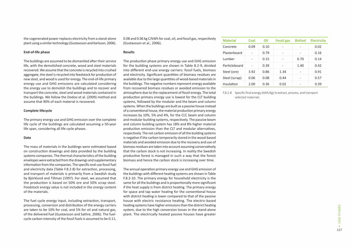
The mass of materials in the buildings were estimated based on construction drawings and data provided by the building systems companies. The thermal characteristics of the building envelopes were extracted from the drawings and supplementary information from the companies. The specific end-use fossil fuel and electricity data (Table F.8.2-8) for extraction, processing, and transport of materials is primarily from a Swedish study by Björklund and Tillman (1997). For steel, we assumed that the production is based on 50% ore and 50% scrap steel. Feedstock energy value is not included in the energy content of the materials.
The fuel cycle energy input, including extraction, transport, processing, conversion and distribution of the energy carriers are taken to be 10% for coal, and 5% for oil and natural gas, of the delivered fuel (Gustavsson and Sathre, 2006). The fuel-cycle carbon intensity of the fossil fuels is assumed to be 0.11,
0.08 and 0.06 kg C/kWh for coal, oil, and fossil gas, respectively (Gustavsson et al., 2006).
Results
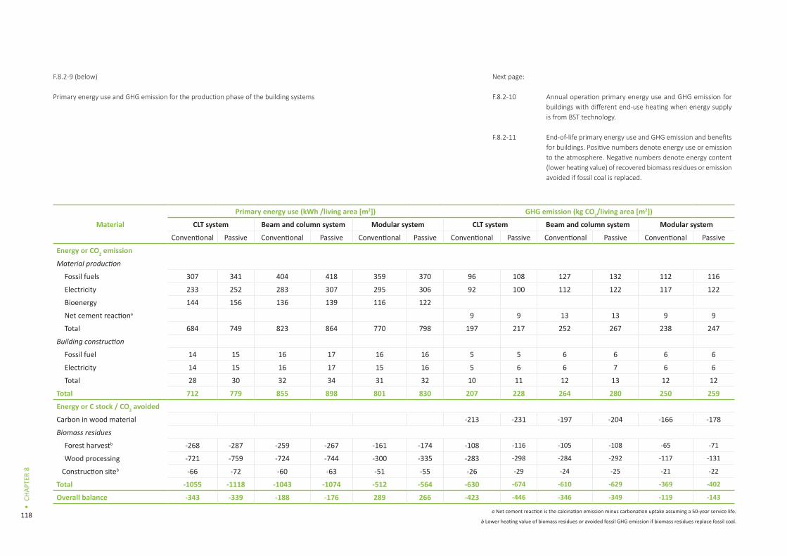
The production phase primary energy use and GHG emission for the building systems are shown in Table 8.2-9, divided into different end-use energy carriers: fossil fuels, biomass and electricity. Significant quantities of biomass residues are available due to the large quantities of wood-based materials in the buildings. The negative numbers represent energy available from recovered biomass residues or avoided emission to the atmosphere due to the replacement of fossil energy. The total production primary energy use is lowest for the CLT building systems, followed by the modular and the beam and column systems. When the buildings are built as a passive house instead of a conventional house, the material production primary energy increases by 10%, 5% and 4%, for the CLT, beam and column and modular building systems, respectively. The passive beam and column building system has 18% and 8% higher material production emission than the CLT and modular alternatives, respectively. The net carbon emission of all the building systems is negative if the carbon temporarily stored in the wood-based materials and avoided emission due to the recovery and use of biomass residues are taken into account assuming conservatively that the carbon stock is not increasing. In reality the Swedish productive forest is managed in such a way that the forest biomass and hence the carbon stock is increasing over time.
The annual operation primary energy use and GHG emission of the buildings with different heating systems are shown in Table F.8.2-10. The primary energy for household electricity is the same for all the buildings and is proportionally more significant if the heat supply is from district heating. The primary energy for space and tap water heating for the conventional house with district heating is lower compared to that of the passive house with electric resistance heating. The electric-based heating systems have higher emissions than the district heating system, due to the high conversion losses in the stand-alone plant. The electrically heated passive houses have greater
Material Coal Oil Fossil gas Biofuel Electricity
Concrete 0.09 0.10 - - 0.02
Plasterboard - 0.79 - - 0.16
Lumber - 0.15 - 0.70 0.14
Particleboard - 0.39 - 1.40 0.42
Steel (ore) 3.92 0.86 1.34 - 0.91
Steel (scrap) 0.06 0.08 0.44 - 0.57
Insulation 2.00 0.36 0.02 - 0.39
Specific final energy (kWh/kg) to extract, process, and transport selected materials.
F.8.2-8
118
CHAP
TER
8
•
Primary energy use and GHG emission for the production phase of the building systems
a Net cement reaction is the calcination emission minus carbonation uptake assuming a 50-year service life.
b Lower heating value of biomass residues or avoided fossil GHG emission if biomass residues replace fossil coal.
Material
Primary energy use (kWh /living area [m2]) GHG emission (kg CO2/living area [m2])
CLT system Beam and column system Modular system CLT system Beam and column system Modular system
Conventional Passive Conventional Passive Conventional Passive Conventional Passive Conventional Passive Conventional Passive
Energy or CO2 emission
Material production
Fossil fuels 307 341 404 418 359 370 96 108 127 132 112 116
Electricity 233 252 283 307 295 306 92 100 112 122 117 122
Bioenergy 144 156 136 139 116 122
Net cement reactiona 9 9 13 13 9 9
Total 684 749 823 864 770 798 197 217 252 267 238 247
Building construction
Fossil fuel 14 15 16 17 16 16 5 5 6 6 6 6
Electricity 14 15 16 17 15 16 5 6 6 7 6 6
Total 28 30 32 34 31 32 10 11 12 13 12 12
Total 712 779 855 898 801 830 207 228 264 280 250 259
Energy or C stock / CO2 avoided
Carbon in wood material -213 -231 -197 -204 -166 -178
Biomass residues
Forest harvestb -268 -287 -259 -267 -161 -174 -108 -116 -105 -108 -65 -71
Wood processing -721 -759 -724 -744 -300 -335 -283 -298 -284 -292 -117 -131
Construction siteb -66 -72 -60 -63 -51 -55 -26 -29 -24 -25 -21 -22
Total -1055 -1118 -1043 -1074 -512 -564 -630 -674 -610 -629 -369 -402
Overall balance -343 -339 -188 -176 289 266 -423 -446 -346 -349 -119 -143
F.8.2-9 (below) Next page:
F.8.2-10
F.8.2-11
Annual operation primary energy use and GHG emission for buildings with different end-use heating when energy supply is from BST technology.
End-of-life primary energy use and GHG emission and benefits for buildings. Positive numbers denote energy use or emission to the atmosphere. Negative numbers denote energy content (lower heating value) of recovered biomass residues or emission avoided if fossil coal is replaced.

119
CASE
STU
DIES
•
Material Primary energy use (kWh /m2 [living area]) GHG emission (kg CO2/m2 [living area])
CLT system Beam and column system Modular system CLT system Beam and column system Modular systemConventional Passive Conventional Passive Conventional Passive Conventional Passive Conventional Passive Conventional Passive
Electric resistance heatedSpace heating 186.5 64.3 189 78.4 188.2 77.2 6.6 2.3 6.6 2.7 6.6 2.7Tap water heating 74.7 44.8 74.7 44.8 74.6 44.8 2.6 1.6 2.6 1.6 2.6 1.6Ventilation electricity 7.6 15.3 7.6 15.3 7.6 15.3 0.2 0.6 0.2 0.6 0.2 0.6Household electricity 94.4 94.4 94.4 94.4 94.3 94.3 3.3 3.3 3.3 3.3 3.3 3.3Facility electricity 39.6 39.6 39.6 39.6 39.5 39.5 1.4 1.4 1.4 1.4 1.4 1.4Total from Operation 402.8 258.4 405.3 272.5 404.2 271.1 14.1 9.2 14.1 9.6 14.1 9.6Heat pump heatedSpace heating 64.3 22.1 65.1 27 64.9 26.7 2.5 0.9 2.5 1 2.5 1.0Tap water heating 25.8 15.5 25.8 15.5 25.7 15.5 1 0.6 1 0.6 1.0 0.6Ventilation electricity 7.6 15.3 7.6 15.3 7.6 15.3 0.2 0.6 0.2 0.6 0.2 0.6Household electricity 94.4 94.4 94.4 94.4 94.3 94.3 3.3 3.3 3.3 3.3 3.3 3.3Facility electricity 39.6 39.6 39.6 39.6 39.5 39.5 1.4 1.4 1.4 1.4 1.4 1.4Total from Operation 231.7 186.9 232.5 191.8 232.0 191.3 8.4 6.8 8.4 6.9 8.4 6.9District heatedSpace heating 47.1 16.2 47.7 19.7 47.5 19.5 1.6 0.6 1.6 0.7 1.6 0.7Tap water heating 18.8 11.3 18.8 11.3 18.8 11.3 0.7 0.3 0.7 0.3 0.7 0.3Ventilation electricity 7.6 15.3 7.6 15.3 7.6 15.3 0.2 0.6 0.2 0.6 0.2 0.6Household electricity 94.4 94.4 94.4 94.4 94.3 94.3 3.3 3.3 3.3 3.3 3.3 3.3Facility electricity 39.6 39.6 39.6 39.6 39.5 39.5 1.4 1.4 1.4 1.4 1.4 1.4
Total from Operation 207.5 176.8 208.1 180.3 207.7 179.9 7.2 6.2 7.2 6.3 7.2 6.3
Material Primary energy use (kWh / m2 [living area]) GHG emission (kg CO2/ m2 [living area])
CLT system Beam and column system Modular system CLT system Beam and column system Modular systemConventional Passive Conventional Passive Conventional Passive Conventional Passive Conventional Passive Conventional Passive
Demolition energy use 11 11 11 11 11 11 3 3 3 3 3 3End-of-life benefits:
Concrete recycling -2 -2 -2 -2 -2 -2 -1 -1 -1 -1 -1 -1Steel recycling -16 -16 -40 -40 -11 -11 -6 -6 -14 -14 -3 -3Wood recovery for bioenergy
-527 -572 -486 -503 -409 -439 -213 -231 -196 -203 -165 -178
Total -534 -579 -517 -534 -411 -441 -217 -235 -208 -215 -166 -179
F.8.2-10
F.8.2-11

120
CHAP
TER
8
•
0
Steel recycling Concrete recycling
0
CLTsystem
Beam &columnsystem
Modularsystem
CLTsystem
Beam &columnsystem
Modularsystem
Passive Conven onal
CLTsystem
Beam &columnsystem
Modularsystem
CLTsystem
Beam &columnsystem
Modularsystem
Passive Conven onal
Prim
ary
and
embo
died
ene
rgy
[kW
h/m
2 ]
Carb
on d
ioxi
de fl
ow a
nd st
ock
[kgC
O2/m
2 ]
3000
4500 500
250
0
-250
-500
-750
1500
-1500
-3000
operation primary energy use and emissions compared to the district heated conventional houses.
Table F.8.2-11 shows the end-of-life phase primary energy and GHG implications of the buildings. The passive houses give a greater end-of-life primary energy benefit than the conventional houses. The energy and GHG benefits of demolished wood are most significant, due to the use of wood-based materials in the buildings. The energy benefit of recycling steel is small. The primary energy benefit through recycling of concrete is minor and similar for all the houses.
The primary energy use for tap water heating and for household and facility electricity constitutes a significant part of the operation energy, but these demands depend to a large extent on the users and not on the construction. Figure 8.2-12a and 8.2-12b show the primary energy and carbon emission for production, space heating and ventilation during 50 years, and end-of-life for the buildings, respectively. The buildings are district-heated and the energy supply
is based on BST technology. The operation phase dominates the lifecycle primary energy use for both the conventional and the passive house versions of the building system. Material production accounts for a large share of the lifecycle GHG emissions for the buildings, as energy supply is based on biomass-based district heating. Overall, the CLT building systems have slightly lower life cycle primary energy use and emissions compared to the beam and column or the modular building systems.
Conclusions
In this study, we have explored the role of wood in carbon efficient construction and analyzed the climate implications of three wood building systems with different level of energy- efficiency. The building systems comprise CLT, beam and column and the modular systems. Our results show the importance of a system-wide life cycle perspective and choice of heating system in reducing primary energy use and GHG emissions in the built environment. Final energy use is significantly lower when the building systems
are constructed as a passive house. Still, the operation primary energy use and GHG emissions for the electrically heated passive houses are greater compared to the district heated conventional alternatives, showing the importance of the heat supply system.
Large amounts of biomass residues are produced due to the use of wood framing material for the building systems. The energy content of the residues is significant relative to the primary energy used for production of the buildings. The primary energy for operation still dominates for a building constructed as a passive house. The passive house versions of the building systems with cogeneration-based district heating give low life cycle primary energy use and GHG emissions. Overall, the CLT system passive house gives the lowest life cycle primary energy and GHG balances, as this system has better airtightness compared to the other building systems studied. Hence improved airtightness is crucial to achieve a low energy building. In summary, wood-frame passive houses with an energy-efficient heat supply reduce climate impacts.
Primary energy use (a) and GHG emission (b) for the life cycle phases of the district heated buildings with assumed life span of 50 years. Energy supply is based on BST technology. Positive numbers denote energy use or GHG emission to the atmosphere. Negative numbers denote the lower heating value of recovered biomass residues or GHG emissions avoided if fossil coal is replaced.
F.8.2-12a (left)F.8.2-12b (right)
Next page:From left to rightF.8.2-13F.8.2-14F.8.2-15
121
CASE
STU
DIES
•
8.2.2 Attributional approach
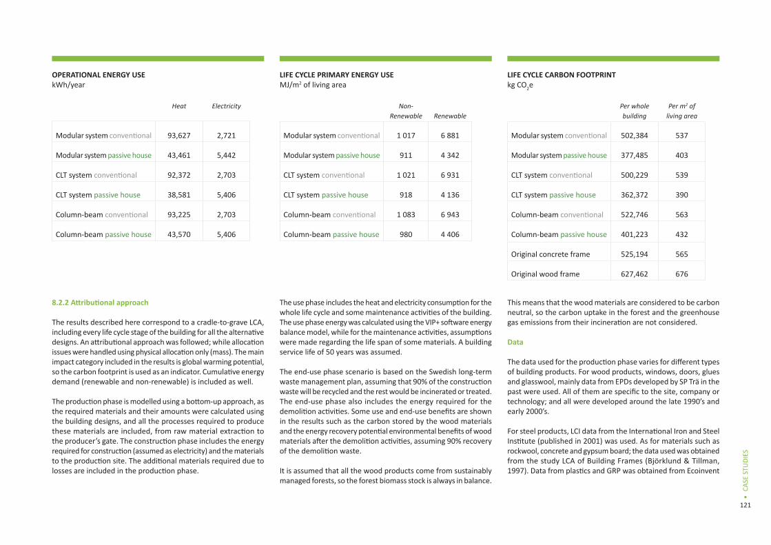
The results described here correspond to a cradle-to-grave LCA, including every life cycle stage of the building for all the alternative designs. An attributional approach was followed; while allocation issues were handled using physical allocation only (mass). The main impact category included in the results is global warming potential, so the carbon footprint is used as an indicator. Cumulative energy demand (renewable and non-renewable) is included as well.
The production phase is modelled using a bottom-up approach, as the required materials and their amounts were calculated using the building designs, and all the processes required to produce these materials are included, from raw material extraction to the producer’s gate. The construction phase includes the energy required for construction (assumed as electricity) and the materials to the production site. The additional materials required due to losses are included in the production phase.
The use phase includes the heat and electricity consumption for the whole life cycle and some maintenance activities of the building. The use phase energy was calculated using the VIP+ software energy balance model, while for the maintenance activities, assumptions were made regarding the life span of some materials. A building service life of 50 years was assumed.
The end-use phase scenario is based on the Swedish long-term waste management plan, assuming that 90% of the construction waste will be recycled and the rest would be incinerated or treated. The end-use phase also includes the energy required for the demolition activities. Some use and end-use benefits are shown in the results such as the carbon stored by the wood materials and the energy recovery potential environmental benefits of wood materials after the demolition activities, assuming 90% recovery of the demolition waste.
It is assumed that all the wood products come from sustainably managed forests, so the forest biomass stock is always in balance.
This means that the wood materials are considered to be carbon neutral, so the carbon uptake in the forest and the greenhouse gas emissions from their incineration are not considered.
Data
The data used for the production phase varies for different types of building products. For wood products, windows, doors, glues and glasswool, mainly data from EPDs developed by SP Trä in the past were used. All of them are specific to the site, company or technology; and all were developed around the late 1990’s and early 2000’s.
For steel products, LCI data from the International Iron and Steel Institute (published in 2001) was used. As for materials such as rockwool, concrete and gypsum board; the data used was obtained from the study LCA of Building Frames (Björklund & Tillman, 1997). Data from plastics and GRP was obtained from Ecoinvent
LIFE CYCLE CARBON FOOTPRINTkg CO2e
Per whole building
Per m2 of living area
Modular system conventional 502,384 537
Modular system passive house 377,485 403
CLT system conventional 500,229 539
CLT system passive house 362,372 390
Column-beam conventional 522,746 563
Column-beam passive house 401,223 432
Original concrete frame 525,194 565
Original wood frame 627,462 676
LIFE CYCLE PRIMARY ENERGY USEMJ/m2 of living area
Non-Renewable Renewable
Modular system conventional 1 017 6 881
Modular system passive house 911 4 342
CLT system conventional 1 021 6 931
CLT system passive house 918 4 136
Column-beam conventional 1 083 6 943
Column-beam passive house 980 4 406
OPERATIONAL ENERGY USEkWh/year
Heat Electricity
Modular system conventional 93,627 2,721
Modular system passive house 43,461 5,442
CLT system conventional 92,372 2,703
CLT system passive house 38,581 5,406
Column-beam conventional 93,225 2,703
Column-beam passive house 43,570 5,406

122
CHAP
TER
8
•
and the ELCD database 2.0. All this data is generic, and consists of industrial averages.
Regarding the use phase heat production, specific data from Växjö energy was used from their 2011 environmental report. The Swedish electricity production mix was modelled using official statistics from the Swedish Energy Agency and EPDs from Vattenfall, the biggest electricity producer in the country. The end-use phase treatment and recycling processes are all modelled using Ecoinvent data, similar to the materials transport to the site in the construction phase. As for the energy for construction and demolition activities, data from Björklund & Tillman was used.
Results
Primary energy demand
There is an obvious trend comparing different energy efficiency standards for each building system, with around 30% savings in primary energy going from conventional buildings to passive
houses. When comparing different building systems there is no notable difference, with the CLT system having slightly less primary energy use than the others.
Carbon footprint
The modular and CLT systems have a lower carbon footprint than the other two systems. The same trend of a 30% lower carbon footprint can be observed from adopting the passive house design.
Other findings
One interesting aspect to point out from these findings is that there seems to be a correlation between carbon footprint and primary energy use, as the differences between designs are proportionally very similar.
It can also be noted that the small difference in living area did not affect much the results for the modular system, which implies that the space distribution for all the designs can be comparable.
Conclusions
The results show that from a life cycle perspective, the benefits of lowering the use phase energy demand by adding additional insulation are significantly higher than the additional environmental impact from producing the additional insulation. This means that for both the carbon footprint and primary energy use, passive house designs are more eco-efficient than conventional designs.
The carbon footprint for all the wood-framed designs is lower than for a concrete-frame design. Even as an old energy efficiency standard was used for the latter, which means that they are not really comparable to the modern designs modelled in this assessment. Nevertheless, they can be compared to the wood frame design for the original building, and still the carbon footprint is around 15% lower. This difference can be estimated to rise to 30% in the case of passive house concrete and wood frame designs.
When measuring the contribution to the carbon footprint and energy use by material group, the mineral-based materials account
0
100
200
300
400
500
600
700
800
Product Stage(Modules A1-A3)
Construc on Process Stage(Modules A4 & A5)
Use Stage(Modules B1 & B2)
End of Life Stage(Modules C1 - C4)
Cum
ula
ve E
nerg
y De
man
d (k
Wh/
m2 o
f liv
ing
area
)
Modular system StdModular system PH
CLT system StdCLT system PH
Column-Beam StdColumn-Beam PH
Original Wood FrameOriginal Concrete Frame
Modular system StdModular system PH
CLT system StdCLT system PH
Column-Beam StdColumn-Beam PH
Original Wood FrameOriginal Concrete Frame
Modular system StdModular system PH
CLT system StdCLT system PH
Column-Beam StdColumn-Beam PH
Original Wood FrameOriginal Concrete Frame
0
2000
4000
6000
8000
10000
12000
14000
16000
Product Stage(Modules A1-A3)
Construc on Process Stage(Modules A4 & A5)
Use Stage(Modules B1 & B2)
End of Life Stage(Modules C1 - C4)
Cum
ula
ve E
nerg
y De
man
d(k
Wh/
m2 o
f liv
ing
area
)
Product Stage(Modules A1-
A3)
Construc onProcess Stage(Modules A4
& A5)
Opera onalEnergy Use
(Module B6)
Use PhaseMaintenance(Module B2)
Use PhaseConcrete
Carbona on(Module B1)
End of LifeStage
(Modules C1 -C4)
BenefitsBeyondSystem
Boundary(Module D)
foraC rbon storedin wood100 years
0
50
100
150
200
250
CO2 E
miss
ions
[kgC
O2eq
/m2 o
f liv
ing
area
][k
gCO
2eq/m
2 of l
ivin
g ar
ea]
OthersDoorsWindowsAsphalt shee ngFiller
PaintWood and wood materialsSteelPlas cs and adhesives
GlassMineral woolGypsum plaster boardConcrete
OthersDoorsWindowsAsphalt shee ngFiller
PaintWood and wood materialsSteelPlas cs and adhesives
GlassMineral woolGypsum plaster boardConcrete
Original DesignWood
Original Design
Concrete
Modularsystem Co
Modularsystem PH
CLT system Co
CLT system PH
Columnbeam Co
Columnbeam PH
0
100
200
300
400
500
600
Original DesignWood
Original Design
Concrete
Modularsystem Co
Modularsystem PH
CLT system Co
CLT system PH
Columnbeam Co
Columnbeam PH
OthersDoorsWindowsAsphalt shee ngFiller
PaintWood and wood materialsSteelPlas cs and adhesives
GlassMineral woolGypsum plaster boardConcrete
Concrete Steel Timber-framed
Timber Plus
CLT(L’Aquila)
PE-nr 486.99 622.45 533.65 429.30 421.60
0
100
200
300
400
500
600
700
[MJ/
m2 ]
0
100
200
300
400
500
600
700
Cum
ulati
ve E
nerg
y De
man
d (k
Wh/
m2 o
f liv
ing
area
)
700
500
300
100
-100
-300
[kgC
o2eq
/m2 o
f liv
ing
area
]
CO2 e
mis
sion
s
Original Design
ConcreteFrame
Modularsystem Co
Modularsystem PvH
CLTsystem Co
CLT system Co
Columnbeam Co
Columnbeam PvH
OthersDoorsWindowsAsphalt sheetingFillerPaintWood and wood materialsSteelPlastics and adhesivesGlassMineral woolGypsum plaster boardConcrete
Cum
ulati
ve E
nerg
y De
man
d [k
Wh/
m2 o
f liv
ing
area
]
0
100
200
300
400
500
600
700
800
Product Stage(Modules A1-A3)
Construc on Process Stage(Modules A4 & A5)
Use Stage(Modules B1 & B2)
End of Life Stage(Modules C1 - C4)
Cum
ula
ve E
nerg
y De
man
d (k
Wh/
m2 o
f liv
ing
area
)
Modular system StdModular system PH
CLT system StdCLT system PH
Column-Beam StdColumn-Beam PH
Original Wood FrameOriginal Concrete Frame
Modular system StdModular system PH
CLT system StdCLT system PH
Column-Beam StdColumn-Beam PH
Original Wood FrameOriginal Concrete Frame
Modular system StdModular system PH
CLT system StdCLT system PH
Column-Beam StdColumn-Beam PH
Original Wood FrameOriginal Concrete Frame
0
2000
4000
6000
8000
10000
12000
14000
16000
Product Stage(Modules A1-A3)
Construc on Process Stage(Modules A4 & A5)
Use Stage(Modules B1 & B2)
End of Life Stage(Modules C1 - C4)
Cum
ula
ve E
nerg
y De
man
d(k
Wh/
m2 o
f liv
ing
area
)
Product Stage(Modules A1-
A3)
Construc onProcess Stage(Modules A4
& A5)
Opera onalEnergy Use
(Module B6)
Use PhaseMaintenance(Module B2)
Use PhaseConcrete
Carbona on(Module B1)
End of LifeStage
(Modules C1 -C4)
BenefitsBeyondSystem
Boundary(Module D)
foraC rbon storedin wood100 years
0
50
100
150
200
250
CO2 E
miss
ions
[kgC
O2eq
/m2 o
f liv
ing
area
][k
gCO
2eq/m
2 of l
ivin
g ar
ea]
OthersDoorsWindowsAsphalt shee ngFiller
PaintWood and wood materialsSteelPlas cs and adhesives
GlassMineral woolGypsum plaster boardConcrete
OthersDoorsWindowsAsphalt shee ngFiller
PaintWood and wood materialsSteelPlas cs and adhesives
GlassMineral woolGypsum plaster boardConcrete
Original DesignWood
Original Design
Concrete
Modularsystem Co
Modularsystem PH
CLT system Co
CLT system PH
Columnbeam Co
Columnbeam PH
0
100
200
300
400
500
600
Original DesignWood
Original Design
Concrete
Modularsystem Co
Modularsystem PH
CLT system Co
CLT system PH
Columnbeam Co
Columnbeam PH
OthersDoorsWindowsAsphalt shee ngFiller
PaintWood and wood materialsSteelPlas cs and adhesives
GlassMineral woolGypsum plaster boardConcrete
Concrete Steel Timber-framed
Timber Plus
CLT(L’Aquila)
PE-nr 486.99 622.45 533.65 429.30 421.60
0
100
200
300
400
500
600
700
[MJ/
m2 ]
0
100
200
300
400
500
600
700
Cum
ulati
ve E
nerg
y De
man
d (k
Wh/
m2 o
f liv
ing
area
)
700
500
300
100
-100
-300
[kgC
o2eq
/m2 o
f liv
ing
area
]
CO2 e
mis
sion
s
Original Design
ConcreteFrame
Modularsystem Co
Modularsystem PvH
CLTsystem Co
CLT system Co
Columnbeam Co
Columnbeam PvH
OthersDoorsWindowsAsphalt sheetingFillerPaintWood and wood materialsSteelPlastics and adhesivesGlassMineral woolGypsum plaster boardConcrete
Cum
ulati
ve E
nerg
y De
man
d [k
Wh/
m2 o
f liv
ing
area
]
F.8.2-16 CO2 emissions from the production phase F.8.2-17CO2 emissions for the building’s life cycle (50 year service)

123
CASE
STU
DIES
•
0
100
200
300
400
500
600
700
800
Product Stage(Modules A1-A3)
Construc on Process Stage(Modules A4 & A5)
Use Stage(Modules B1 & B2)
End of Life Stage(Modules C1 - C4)
Cum
ula
ve E
nerg
y De
man
d (k
Wh/
m2 o
f liv
ing
area
)
Modular system StdModular system PH
CLT system StdCLT system PH
Column-Beam StdColumn-Beam PH
Original Wood FrameOriginal Concrete Frame
Modular system StdModular system PH
CLT system StdCLT system PH
Column-Beam StdColumn-Beam PH
Original Wood FrameOriginal Concrete Frame
Modular system StdModular system PH
CLT system StdCLT system PH
Column-Beam StdColumn-Beam PH
Original Wood FrameOriginal Concrete Frame
0
2000
4000
6000
8000
10000
12000
14000
16000
Product Stage(Modules A1-A3)
Construc on Process Stage(Modules A4 & A5)
Use Stage(Modules B1 & B2)
End of Life Stage(Modules C1 - C4)
Cum
ula
ve E
nerg
y D
eman
d(k
Wh/
m2 o
f liv
ing
area
)
Product Stage(Modules A1-
A3)
Construc onProcess Stage(Modules A4
& A5)
Opera onalEnergy Use
(Module B6)
Use PhaseMaintenance(Module B2)
Use PhaseConcrete
Carbona on(Module B1)
End of LifeStage
(Modules C1 -C4)
BenefitsBeyondSystem
Boundary(Module D)
foraC rbon storedin wood100 years
0
50
100
150
200
250
CO2 E
miss
ions
[kgC
O2eq
/m2 o
f liv
ing
area
][k
gCO
2eq/m
2 of l
ivin
g ar
ea]
OthersDoorsWindowsAsphalt shee ngFiller
PaintWood and wood materialsSteelPlas cs and adhesives
GlassMineral woolGypsum plaster boardConcrete
OthersDoorsWindowsAsphalt shee ngFiller
PaintWood and wood materialsSteelPlas cs and adhesives
GlassMineral woolGypsum plaster boardConcrete
Original DesignWood
Original Design
Concrete
Modularsystem Co
Modularsystem PH
CLT system Co
CLT system PH
Columnbeam Co
Columnbeam PH
0
100
200
300
400
500
600
Original DesignWood
Original Design
Concrete
Modularsystem Co
Modularsystem PH
CLT system Co
CLT system PH
Columnbeam Co
Columnbeam PH
OthersDoorsWindowsAsphalt shee ngFiller
PaintWood and wood materialsSteelPlas cs and adhesives
GlassMineral woolGypsum plaster boardConcrete
Concrete Steel Timber-framed
Timber Plus
CLT(L’Aquila)
PE-nr 486.99 622.45 533.65 429.30 421.60
0
100
200
300
400
500
600
700
[MJ/
m2 ]
0
100
200
300
400
500
600
700
Cum
ulati
ve E
nerg
y De
man
d (k
Wh/
m2 o
f liv
ing
area
)
700
500
300
100
-100
-300
[kgC
o2eq
/m2 o
f liv
ing
area
]
CO2 e
mis
sion
s
Original Design
ConcreteFrame
Modularsystem Co
Modularsystem PvH
CLTsystem Co
CLT system Co
Columnbeam Co
Columnbeam PvH
OthersDoorsWindowsAsphalt sheetingFillerPaintWood and wood materialsSteelPlastics and adhesivesGlassMineral woolGypsum plaster boardConcrete
Cum
ulati
ve E
nerg
y De
man
d [k
Wh/
m2 o
f liv
ing
area
]
for a significant share of the environmental impact, even as the proportion in mass is not that different. This is more relevant for the column-beam system, when an additional amount of concrete increased the total environmental impact of the building.
In general, the kind of building system used for building design has a low influence on the associated environmental impact. Furthermore, the choice of energy efficiency category is much more influential; while the type of materials used (bio-based or mineral-based) can influence the result too. The influence of the choice of material increases with higher use phase energy efficiency, as the gap between the use phase and the production phase closes and the production phase becomes more influential.
This means that for future designs with increased use phase energy efficiency, the production and end-of-life stages will be more relevant, and so will be the choice of material.
8.2.3 Final conclusions
The results of the two approaches seem to be similar but differ in magnitude, due to the differences in methodological approaches, e.g., the system boundary definition, the assumed electricity supply, and solving allocation issues. The consequential approach use data on marginal electricity production in northern Europe, which is considered to be coal-based, while the attributional approach used data on the Swedish average national electricity mix, which is based mainly on hydro and nuclear power. In general, both the attributional and consequential approaches show that the CLT system passive house gives the lowest life cycle primary energy and GHG balances, compared to the other building systems. This study illustrates the significance of the approach for a life cycle climate impact analysis of buildings.
F.8.2-18 Renewable energy demand for the production phase
F.8.2-19
0
100
200
300
400
500
600
700
800
Product Stage(Modules A1-A3)
Construc on Process Stage(Modules A4 & A5)
Use Stage(Modules B1 & B2)
End of Life Stage(Modules C1 - C4)
Cum
ula
ve E
nerg
y De
man
d (k
Wh/
m2 o
f liv
ing
area
)
Modular system StdModular system PH
CLT system StdCLT system PH
Column-Beam StdColumn-Beam PH
Original Wood FrameOriginal Concrete Frame
Modular system StdModular system PH
CLT system StdCLT system PH
Column-Beam StdColumn-Beam PH
Original Wood FrameOriginal Concrete Frame
Modular system StdModular system PH
CLT system StdCLT system PH
Column-Beam StdColumn-Beam PH
Original Wood FrameOriginal Concrete Frame
0
2000
4000
6000
8000
10000
12000
14000
16000
Product Stage(Modules A1-A3)
Construc on Process Stage(Modules A4 & A5)
Use Stage(Modules B1 & B2)
End of Life Stage(Modules C1 - C4)
Cum
ula
ve E
nerg
y De
man
d(k
Wh/
m2 o
f liv
ing
area
)
Product Stage(Modules A1-
A3)
Construc onProcess Stage(Modules A4
& A5)
Opera onalEnergy Use
(Module B6)
Use PhaseMaintenance(Module B2)
Use PhaseConcrete
Carbona on(Module B1)
End of LifeStage
(Modules C1 -C4)
BenefitsBeyondSystem
Boundary(Module D)
foraC rbon storedin wood100 years
0
50
100
150
200
250
CO2 E
miss
ions
[kgC
O2eq
/m2 o
f liv
ing
area
][k
gCO
2eq/m
2 of l
ivin
g ar
ea]
OthersDoorsWindowsAsphalt shee ngFiller
PaintWood and wood materialsSteelPlas cs and adhesives
GlassMineral woolGypsum plaster boardConcrete
OthersDoorsWindowsAsphalt shee ngFiller
PaintWood and wood materialsSteelPlas cs and adhesives
GlassMineral woolGypsum plaster boardConcrete
Original DesignWood
Original Design
Concrete
Modularsystem Co
Modularsystem PH
CLT system Co
CLT system PH
Columnbeam Co
Columnbeam PH
0
100
200
300
400
500
600
Original DesignWood
Original Design
Concrete
Modularsystem Co
Modularsystem PH
CLT system Co
CLT system PH
Columnbeam Co
Columnbeam PH
OthersDoorsWindowsAsphalt shee ngFiller
PaintWood and wood materialsSteelPlas cs and adhesives
GlassMineral woolGypsum plaster boardConcrete
Concrete Steel Timber-framed
Timber Plus
CLT(L’Aquila)
PE-nr 486.99 622.45 533.65 429.30 421.60
0
100
200
300
400
500
600
700
[MJ/
m2 ]
0
100
200
300
400
500
600
700
Cum
ulati
ve E
nerg
y D
eman
d (k
Wh/
m2 o
f liv
ing
area
)
700
500
300
100
-100
-300
[kgC
o2eq
/m2 o
f liv
ing
area
]
CO2 e
mis
sion
s
Original Design
ConcreteFrame
Modularsystem Co
Modularsystem PvH
CLTsystem Co
CLT system Co
Columnbeam Co
Columnbeam PvH
OthersDoorsWindowsAsphalt sheetingFillerPaintWood and wood materialsSteelPlastics and adhesivesGlassMineral woolGypsum plaster boardConcrete
Cum
ulati
ve E
nerg
y De
man
d [k
Wh/
m2 o
f liv
ing
area
]
Non-renewable energy demand for the production phase

124
CHAP
TER
8
•
A. Takano
This building is a four-story apartment building located at a former military site in Mietraching, approximately 50 km south-east of Munich. The area was bought by B&O, a real estate developer, and redevelopment was planned as a “zero-energy/emission” model city.
Most of the existing buildings on the site were deconstructed because of pollution with harmful substances. However, since the basement, which was originally a bunker with a thick wall, was in relatively good condition, it was utilized for new construction. Wood construction was selected because of its lightness for the existing basement structure, ecological aspect, high level of prefabrication and short construction period. This project demonstrated that wood can be used as the primary structural component for multi-story dwellings.
As a common problem with wood constructions, fire safety and sound protection were the main challenges in this project. For fire safety reasons, the load bearing structure is required as an REI60. This criterion is achieved with K260 encapsulation that consists of two layers of gypsum fibre board with 18mm thickness each as an interior layer. The exterior wall is required to be made from non-combustible materials by the fire regulations. The solution
was a closed cladding with horizontal fire stops at each storey. For sound protection, the massive glulam ceilings with 200 mm of thickness are finished on top with a layer of gravel and a dry screed system that consists of a soft wood fibre board and a double layer of gypsum fibre board. There is no additional demand for a suspended ceiling for sound protection purposes.
The building is a simple box shape with a balcony made of LVL. All wooden building elements were prefabricated by Huber&Sohn GmbH&Co.KG. The on-site assembly of prefabricated elements took just four days.
For the conditioning of the indoor environment, a heat recovery ventilation system and radiation connected to the district heating system are used.
Buildings from the developer located in the area were designed at a high-energy standard (energy demand should be 50% of EnEV 2009). In addition, several measures were been conducted in order to optimize the environmental impact from energy production, such as modernization of the existing boiler for district heating, a district solar thermal collector, re-heating system with heat pumps for hot water, a biomass boiler, photovoltaic panels, and a small hydroelectric power plant.
4 HolzMietraching, Germany
8.3
F.8.3-1F.8.3-2
The building in its environmentKey figures of the building
F.8.3-3Ground floorplan,1:400
ClientArchitectStructural engineersConstruction company
B&O Parkgelände GmbH & Co.KGSchankula Architekten/DiplomingenieureBauart Konstruktions GmbH + Co.KGHuber&Sohn Gmbh & Co.KG
F.8.3-1
F.8.3-4Upper floor plan, 1.400
F.8.3-5Section, 1:400
KEY FIGURES
Gross floor area 726 m2
Net floor area 615 m2
Living area 488 m2
Gross volume 11 928 m3
Net volume 9 459 m3
Nr of occupants 24 persons
Planned service life 50 years
F.8.3-2

125
CASE
STU
DIES
•
Assessment
For the production stage, module A, all calculations were conducted manually with the help of templates created in this project. For the use stage, module B6, the energy demand for operation of the building was calculated based on the standard (DIN4108-6/EnEV2009 by LCA software LEGEP. In addition, the energy content of wooden materials was calculated with an equation mentioned in the ecoinvent database documentation /1/. Carbon storage capacity of wooden material was also calculated according to the standard (CEN/TC175 WI00175146). The other life cycle modules are excluded from the assessment due to lack of data.
Module A
All information regarding building components was collected from the drawings. Since it was impossible to assess the existing basement directly, a new basement with the same shape as the existing one was assumed and included in the study. Regarding the construction process, prefabrication and on-site assembly of the building elements were covered based on an interview with the constructor. In addition, earthwork and the construction of the basement were assessed by referring to the case study of Joensuun Elli, since the detailed data could be collected in that study. Electricity use for on-site construction is not included due
to a lack of data. In this module, all building service and machinery are excluded from the calculation due to a lack of information.
Energy performance
Module B
Operational energy use was assumed to be 31,83 kWh/m2/year for district heating and 31,31 kWh/m2/year for electricity use in the whole building. As mentioned before, this area is very unique regarding energy production, so it was not possible to specify the real energy mix of district heating system in the area. Therefore, the general German situation was referred to. Mainly the heat comes from CHP plant, which consists of approximately 42% natural gas, 39% coal, 12% lignite, and 7% waste incineration (AGFW 2006). This energy mix was used in the calculation. For the electricity, national average data on supply mix was applied.
Data
ecoinvent ver. 2.2 was used in all calculations. ecoinvent is one of the most well-known LCA databases that consists of process-based LCI data. Geographical coverage is mainly in Europe. Temporal representativeness is the year 2000-2007 as the annual average. Basically stored data is based on an average of currently used
technology. In this study, European average data is applied for the calculation of A1-3, and German average data is applied for A4-5. In principle, exact material data was applied for building materials from the database. However when there was not exact data in the database, the most relevant material data was applied (i.e., plywood data instead of LVL).
Structures and construction methods
Foundation and floors
The existing basement was utilized as the main foundation and an additional foundation was made for the staircase. The floor of the ground floor consists of three layers on top of the basement: rock wool, cement screed, and parquet flooring. The intermediate floor consists of five layers: glulam panel, gravel fixed by latex, mineral wool, cement screed, and parquet flooring. Only the glulam panel slab was prefabricated in a factory, and the other layer was installed on-site.
External walls
The exterior wall consists of eight layers as shown in the section. The U-value is 0,15 W/m2K. This element was prefabricated and assembled on-site in three weeks including secondary work
spacer text/arrow
WALL DETAIL FLOOR DETAILROOF DETAIL
1. Larch cladding2. Spruce batten3. Wind and water barrier sheet4. Rock wool5. Vapour barrier (airtight) sheet6. Gypsum board7. CLT8. Gypsum board
8
3
1
1. Gravel2. Vapour bareer sheet3. Crawl space4. Spruce strips5. Cement bounded particule board6. Cellulose fibre7. I-joist8. Gypsum board9. Parquet flooring
2
45
6
7
9
1. Gravel2. Vapour bareer sheet3. Concrete slab4. EPS5. Softwood plywood6. Parquet flooring
2
1
3
4
65
1. Gravel2. Vapour bareer sheet3. EPS4. Concrete slab5. Parquet flooring1
4
3
5
2
1. Gravel2. Vapour bareer sheet3. EPS4. CLT5. Parquet flooring1
4
3
5
2
1. Steel sheet2. Spruce board3. Spruce batten4. Waterproof sheet5. Softwood plywood6. Cellulose fibre | I-joist7. Vapour bareer sheet8. Cellulose fibre9. Vatpour barrier sheet 10. Gypsum board11. Spruce batten12. Gypsum board
5
6
1 2 3 4
7 8 9 10
8
7
5
6
1 2 3 4
9 10 11 12
1. Steel sheet2. Spruce board3. Spruce batten4. Waterproof sheet5. Softwood plywood6. Timber rafter7. Attic (air)8. Cellulose fibre9. Vapour barrier sheet 10. Gypsum board11. Spruce batten12. Gypsum board
3 5
1 2 4 6 7 8
F.8.3-6Roof detail, 1:10
F.8.3-7Exterior wall detail, 1:10
F.8.3-8Base floor detail, 1:10
spacer text/arrow
WALL DETAIL FLOOR DETAILROOF DETAIL
1. Larch cladding2. Spruce batten3. Wind and water barrier sheet4. Rock wool5. Vapour barrier (airtight) sheet6. Gypsum board7. CLT8. Gypsum board
8
3
1
1. Gravel2. Vapour bareer sheet3. Crawl space4. Spruce strips5. Cement bounded particule board6. Cellulose fibre7. I-joist8. Gypsum board9. Parquet flooring
2
45
6
7
9
1. Gravel2. Vapour bareer sheet3. Concrete slab4. EPS5. Softwood plywood6. Parquet flooring
2
1
3
4
65
1. Gravel2. Vapour bareer sheet3. EPS4. Concrete slab5. Parquet flooring1
4
3
5
2
1. Gravel2. Vapour bareer sheet3. EPS4. CLT5. Parquet flooring1
4
3
5
2
1. Steel sheet2. Spruce board3. Spruce batten4. Waterproof sheet5. Softwood plywood6. Cellulose fibre | I-joist7. Vapour bareer sheet8. Cellulose fibre9. Vatpour barrier sheet 10. Gypsum board11. Spruce batten12. Gypsum board
5
6
1 2 3 4
7 8 9 10
8
7
5
6
1 2 3 4
9 10 11 12
1. Steel sheet2. Spruce board3. Spruce batten4. Waterproof sheet5. Softwood plywood6. Timber rafter7. Attic (air)8. Cellulose fibre9. Vapour barrier sheet 10. Gypsum board11. Spruce batten12. Gypsum board
3 5
1 2 4 6 7 8
Material layers counting from top:1. Steel sheet2. Spruce board3. Spruce batten4. Waterproof sheet5. Softwood plywood6. Cellulose fibre I-joist7. Vapour barrier sheet8. Gypsum board9. Spruce batten10. Gypsum board
Material layers counting from outside:1. Larch cladding2. Spruce batten3. Wind and water barrier sheet4. Rock wool5. Vapour barrier (airtight) sheet6. Gypsum board7. Sawn timber panel8. Gypsum board
Material layers countingfrom below:1. Gravel2. Vapour barrier sheet3. Crawl space4. Spruce strips5. Cement bounded particule board6. Cellulose fibre7. I-joist8. Gypsum board9. Parquet flooring

126
CHAP
TER
8
•
F.8.3-10Primary energy demand MJ/m2 of living areaLife cycle phases A1-5 and B6
F.8.3-11GHG emissionskgCO2e/m2 of living areaLife cycle phases A1-5 and B6
(covering, airtightening, etc.). Some of the installation has been done on-site, such as the entrance door and the window facing the balcony.
Roof
The roof element is composed of six layers, as shown in the section. Above PVC waterproof sheet and finishing of ceiling (plywood) have been installed on-site. The U-value is 0,14 W/m2K.
Other structural features
The load-bearing structure of the wall element consists of a massive timber layer, which is literally a mass of sawn timber laid side by side and fixed with a nail to the LVL frame. Gypsum board is also attached from both sides of the massive timber layer to tighten those and for fire resistance.
Construction work
Prefabrication
All wooden building elements were prefabricated in the factory. This prefabrication work was done in about one month. The prefabrication company also produces window and door products in its factory. All wood waste from the prefabrication process is burned in the factory’s biomass boiler, and generated heat is utilized for drying wood and for space heating in the factory.
The exterior steel staircase was also prefabricated in a factory. However it was excluded from this study due to lack of information.
On-site work
On-site construction work is mainly assembly of the prefabricated element. It was done in three weeks. After that, interior finishing and water-proofing work was done. These on-site finishing works were excluded from this study because of lack of information. The assembly of the steel staircase is included based on an assumption.
F.8.3-9Assembly of the staircase, Mietraching
-2500 -2000 -1500 -1000 -500 0 500 1000 1500 2000
Basement
Exterior walls
Interior walls
Stairs and Staircases
Intermediate floor
Roof
Doors and windows
Exterior walls
Interior walls
Stairs and Staircases
Intermediate floor
Roof
Doors and windows
Basement
PE demand[MJ/m2 of living area]
GHG emissions[MJ/m2 of living area]
Renewable Non-renewable Energy content
Fossil Carbon storage
-250 -200 -150 -100 -50 0 50 100 150
Building elements
Building elements

127
CASE
STU
DIES
•
F.8.3-12 F.8.3-13 F.8.3-14
CARBON FOOTPRINT (A1-5, B6)kgCO2e
per m2 of living area per whole building
Carbon footprint 1 572 767 150
Carbon storage -428 -208 922
Net balance 1 144 558 228
per m2 of livingarea
per whole building
Total 26 825 13 090 811
Renewable 1 632 796 587
Non-renewable 25 193 12 294 224
Energy content -4 029 -1 966 000
Results
Primary energy balance
Use phase energy, module B6, accounts for 70% of total primary energy consumption for module A and B6. The construction process, module A4-5, contributes a very minor impact, about 5% of the total. Energy content is about 4 000 MJ/m2 of living area, which can cover all energy consumption for the construction phase.
Carbon footprint
The same trend is shown in the carbon footprint as the primary energy balance. 70% of GHG emissions originate in module B6, and the production phase emits about 30% of the total. Carbon storage capacity is about 428 kgCO2e/m2 of living area, which corresponds to more or less the same amount of GHG emissions from module A.
Other findings
The basement is the dominant building element regarding the carbon footprint due to its volume for the material production phase (A1-3). In addition, the basement is used as a storage and machine room, which are not included in the living area. Therefore, the result normalized by m2 of living area shows a relatively high value for the production phase. The exterior wall element is the main for primary energy consumption, but on the contrary, it has the largest carbon storage capacity and energy content.
Conclusions
LCA has been conducted for the material production, construction, and operation phase of the building. The main feature of this case study is to conduct detailed data collection for the construction phase, module A4-5. Based on the collected data, the relation between the material production phase and the construction phase for wooden building elements is studied with the two other case studies (see Section 5.4). Actually, the study encountered difficulties in data collection from the construction process.
Proper data collection is required in order to understand the environmental profile of the process. But it is not so easy in the current industrial situation. Further research and development of a practical LCA method for the construction process with reliable quality and ease is important as a next step.
Accuracy of inventories for the assessment of module A1-3 is also an important feature of this study. The amount of each building components were taken off from the detail drawings and material order information given by the constructor as precisely as possible. Therefore, detailed inventories could be made.
In this study, all building service equipment is not included due to lack of information. Building service equipment would have a significant influence on the life cycle environmental impact, especially due to its maintenance. This issue needs to be investigated more.
PRIMARY ENERGY USE (A1-5, B6)MJ
ENERGY PERFORMANCE
Operative energy use30 812,32 kWh/a
63,14 kWh/m2/a
Heat generation District heating
Heat distribution Radiator
Air tightness 0,6 h-1
Energy class EnEV2009

128
CHAP
TER
8
•
F. Dolezal, O. Mair am Tinkhof, H. Mötzl, C. Spitzbart
The aim of the Austrian case studies was to analyse primary energy input and CO2 emissions over the life cycle of very energy efficient residential buildings (Passive houses and Nearly Zero Energy Buildings – NZEB). Three existing buildings that represent typical residential buildings according to the Austrian building typology (developed within the EU project TABULA [Amtmann, Gross 2011]) have been chosen for this analysis. However, the wood construction systems they incorporate are quite innovative and not yet common in Austria.
The multi-storey and the single family building have been built according to the Passive House standard (heating demand of less than 15 kWh/m²a according to PHPP calculation software), while the row house was originally designed as a Low Energy House with an average heating demand according to Austrian building regulations. Within the project, the row house has been virtually changed into a Nearly Zero Energy Building by the use of PV cells. The buildings are supplied with different heating systems but are all equipped with mechanical ventilation with heat recovery.
Austrian buildings8.4
F.8.4-1F.8.4-2F.8.4-3
Multi-storey residential building, ViennaGround floor plan, 1:400Section of the building, 1:400
F.8.4-1
F.8.4-2
Multi-storey building, Mühlweg, ViennaClientArchitectConstruction company
Row house, Steinbrechergasse, ViennaClientConstruction company
Single family house, SchönkirchenClientArchitectConstruction company
BAI Bauträger Austria Immobilien GmbHDietrich | Untertrifaller architectsKLH Massivholz GmbH
Glorit Bausysteme AGGlorit Bausysteme AG
Nicole and Michael HartlPlanungsbüro ARE-Bau GmbHIng. Graf Zimmerei und Holzbau GmbH
F.8.4-3

129
CASE
STU
DIES
•
General assumptions for the assessment and the database used are described at the end of this chapter.
8.4.2 Multi-storey residential building, Vienna
The first presented building (Dietrich | Untertrifaller architects) is a multi-storey residential building located in Mühlweg, Vienna. The apartment complex consists of four blocks comprising 70 flats for approximately 200 inhabitants in total. The project was the winner of a developer and architect contest launched by the City of Vienna and Holzforschung Austria (HFA). It was erected within the financial means of the social housing fund.
The residual heat is provided by a combined solar/gas heating system. All apartments are supplied with fresh air by a central ventilation system.
The basement, the staircase and the load-carrying system of the first floor are made of concrete; the three upper floors and the attic floor show a massive wood construction.
The calculation at hand considers one block, including the proportionate basement.
Structures and construction methods
The characteristic structure of the building is a cross laminated timber (CLT) construction.
Foundation and floors
The building is grounded on a foundation slab made of reinforced concrete, which is based on lean concrete and gravel and equipped with a bitumen coating and 22 cm interior EPS insulation where applicable.
The basement ceiling is made of concrete, all other ceilings are based on cross-laminated timber panels.
The floor construction consists of floor covering and cement screed on glass wool sound insulation and split filling. Gypsum
plaster board panels on adj. strap hangers form the bottom boundary of the ceiling. The basement ceiling is insulated with 36 cm stone wool.
External walls
External walls are made of a prefabricated cross-laminated wood construction with mineral wool between wooden lathes as insulation material. The exterior side of the wall is covered with wood or plastered wood wool panels.
The basement walls consist of 25 cm reinforced concrete with bitumen coating and 5 cm extruded polystyrene foam insulation.
Roof
The flat roofs are also made of CLT. The insulation layers are carried out as a duo roof or as non-ventilated terrace.
Other structural features
• There are several types of wooden inner walls: CLT panels, double CLT panels with mineral wool in between, or wooden frame filled with mineral wool.
• Windows with wooden frames and 3 layer thermal insulation glazing fulfil passive house standard.
• Concrete made inner walls are simply plastered or planked with gypsum plasterboards, respectively, depending on the requirements from building physics.
• Staircases are made of prefabricated concrete.
Construction work
Prefabrication
The building structure exhibits a high degree of prefabrication. All essential structural parts as external walls, floors and roofs
F.8.4-4F.8.4-5
Key figures for one blockEnergy performances of the building
ENERGY PERFORMANCE
Operative energy use74 320 kWh/a
36,2 kWh/m2/a
Heat generationVentilation system, solar/gas heating system radiator
Heat distribution Ventilation system, radiators
Energy generation -Air tightness 0,3 h-1
Energy class Passive house
KEY FIGURES (one block)
Gross floor area 2 052 m2
Living area 1 565 m2
Gross volume 5 269 m3
Net volume 4 269 m3
Nr of occupants 50 persons
Planned service life 50 years

130
CHAP
TER
8
•
are made of prefabricated cross-laminated timber. The external walls were delivered to the site including all windows and façade.
On-site work
Because of the high degree of prefabrication, on-site works are reduced to completing and connecting prefabricated components, supplemental to the interior and landscaping.
8.4.3 Row house, Steinbrechergasse, Vienna
The second presented building is a row house with a gross floor area of 668 m² and a net floor or living area of 531 m², considering all five housing units. All units are equipped with a basement below the entire ground floor. The whole settlement is located in Vienna, Austria, in green surroundings with single family houses.
The whole building originally was designed as a Low Energy House with an average heating demand according to Austrian building regulations. Since one of the fundamental goals of the research project was to determine the environmental impact of Nearly Zero Energy buildings, the whole existing construction was adapted and transferred to a passive house structure with the additional application of PV cells on the roof. Therefore all
F.8.4-6F.8.4-7F.8.4-8
The building in its environment, ViennaKey figures of the buildingEnergy performances of the building
From left to right
F.8.4-9F.8.4-10
PlanSection
From left to right
ENERGY PERFORMANCE
Operative energy use40 240 kWh/a
60,3 kWh/m2/a
Heat generation Central heating pellet boiler
Heat distribution Ventilation system, radiators
Energy generation Photovoltaics (151m2)
Air tightness 0,6 h-1
Energy class Passive house
KEY FIGURES
Gross floor area 668 m2
Living area 531 m2
Gross volume 2 143 m3
Net volume 1 335 m3
Nr of occupants 20 persons
Planned service life 50 years

131
CASE
STU
DIES
•
exterior elements (roof, walls, windows and ground floor slab) were thermally improved by raising the thickness of insulation material. Moreover, the building had to be equipped with a ventilation system with heat recovery.
Structures and construction methods
The structural system of the row house is a wooden post and beam structure with an external thermal insulation composite system (ETICS). The structure is based on a basement made of XPS-insulated concrete walls with a foundation slab of reinforced concrete.
Foundation and floors
The row house is equipped with a basement on a ground slab. The ground slab is a reinforced concrete slab on poor concrete and gravel with insulation and a screed.
The ground floor slab is made of reinforced concrete as well, but shows an impact sound insulation below the screed, insulation below to the basement and parquet or tiles. The first floor slab is a wooden beam structure with mineral wool in the cavities, a dry screed on impact sound-insulation boards.
External walls
External walls are a prefabricated post and beam structure with glass wool in the cavities and an external thermal insulation composite system made of polystyrene.
Roof
The single pitch roof is partly prefabricated and also a wooden beam structure with mineral wool insulation in the cavities and a rear ventilated aluminium roof covering.
Other structural features
Non load bearing inner walls are made of wooden studs, planked with gypsum boards. Windows are wood aluminium frames with 3-layer thermal insulation glazing.
Staircases are made of prefabricated concrete in the basement and wood in the ground floor.
Construction work
Prefabricated reinforced concrete elements are placed and backfilled. Prefabricated wooden walls, floors and roofs are placed on-site as well. Joints in already plastered external walls are filled, and aluminium covering is applied on the roof elements. Stairs are implemented and flooring is completed after setting up inner walls. The last step is to place the different types of floor coverings.
Prefabrication
In this case we can find a very high degree of prefabrication, as all essential structural parts of the row house are prefabricated: wooden components as external walls, floors and roofs as well as components made of concrete.
On-site work
Because of the high of prefabrication, on-site works are reduced to completion and connecting prefabricated components, completion of the interior and landscaping.
WALL
ROOF
INTERMEDIATE FLOOR
1
2
3
4
5
1 2 3 4 5 61 2 3 4 5 6
WALL
ROOF
INTERMEDIATE FLOOR
1
2
3
4
5
1 2 3 4 5 61 2 3 4 5 6
WALL
ROOF
INTERMEDIATE FLOOR
1
2
3
4
5
1 2 3 4 5 61 2 3 4 5 6
F.8.4-11Roof detail
F.8.4-12Wall detail
F.8.4-13Floor detail
1. Roofing (aluminium sheet)2. Ventilation cavity 80mm3. Underlay on planking4. Insulation between wooden beams (280mm)5. Insulation between secondary beams (60mm)6. Suspended ceiling
1. Parquet or tiles2. Gypsum board
3. Footfal sound insulation
1.Gypsum board2. Insulation between wooden columns (140mm)3. Particle board4. Polystyrene (140mm)5. Plaster
4. OSB5. Insulation between beams6. Gypsum board
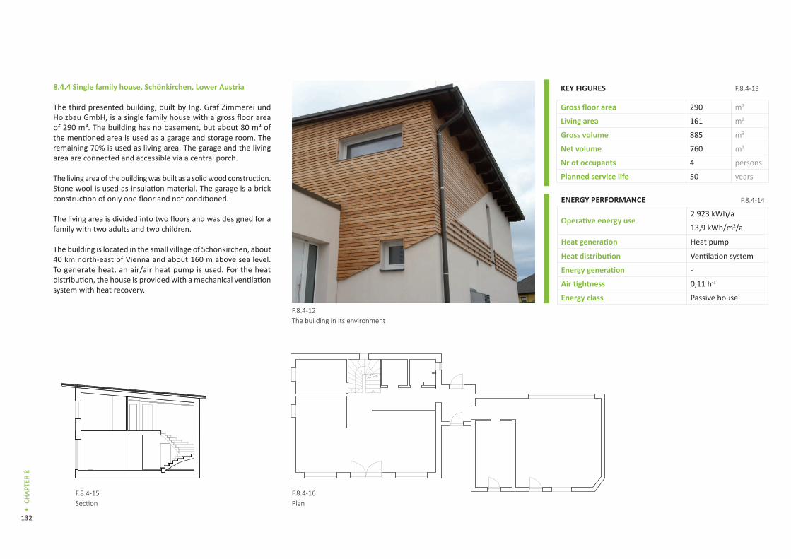
132
CHAP
TER
8
•
8.4.4 Single family house, Schönkirchen, Lower Austria
The third presented building, built by Ing. Graf Zimmerei und Holzbau GmbH, is a single family house with a gross floor area of 290 m². The building has no basement, but about 80 m² of the mentioned area is used as a garage and storage room. The remaining 70% is used as living area. The garage and the living area are connected and accessible via a central porch.
The living area of the building was built as a solid wood construction. Stone wool is used as insulation material. The garage is a brick construction of only one floor and not conditioned.
The living area is divided into two floors and was designed for a family with two adults and two children.
The building is located in the small village of Schönkirchen, about 40 km north-east of Vienna and about 160 m above sea level. To generate heat, an air/air heat pump is used. For the heat distribution, the house is provided with a mechanical ventilation system with heat recovery.
F.8.4-16Plan
F.8.4-12The building in its environment
F.8.4-15Section
ENERGY PERFORMANCE F.8.4-14
Operative energy use2 923 kWh/a
13,9 kWh/m2/a
Heat generation Heat pump
Heat distribution Ventilation system
Energy generation -
Air tightness 0,11 h-1
Energy class Passive house
KEY FIGURES F.8.4-13
Gross floor area 290 m2
Living area 161 m2
Gross volume 885 m3
Net volume 760 m3
Nr of occupants 4 persons
Planned service life 50 years

133
CASE
STU
DIES
•
Structures and construction methods
Foundation and floors
The construction of the foundation consists of reinforced concrete with XPS and EPS insulation. In the residential building, wood parquet is used as flooring in almost all rooms. In the garage, tiles are laid.
External walls
The external walls of the residential building are built as a solid wood construction with stone wool insulation. The thickness of the construction is 42 cm. The U-value is 0,13 W/m²K. The external walls of the garage consist of 16 cm of bricks. As the garage is not conditioned, no thermal insulation was attached to the external walls. The share of the external garage walls to the total external walls is about 40%.
Roof
The roof of the residential building consists of timber rafters and stone wool. The flat roof has a thickness of 42 cm and a U-value of 0,12 W/m²K. The roof of the garage consists of concrete (18 cm) and EPS insulation (10 cm).
Other structural features
The internal walls are built as lightweight timber constructions in the residential building and as solid brick construction in the garage. The rendering of the internal walls consists of loam on reed matting. The inner ceiling is made of cross laminated timber panels.
The stairs and door and window frames are also made out of wood. Windows are equipped with 3-layer thermal insulation glazing. The windows have a U-value of about 0,7 W/m²K (depending on the area and orientation).
Construction work
The construction works were carried out by a small-sized carpenter company with major input from the building owners.
Prefabrication
All essential structural parts of the external building shell (walls including windows, roof) are made of prefabricated cross-laminated timber. They were delivered to the site where they have been completed with a special focus on airtightness.
On-site work
Because of the high of prefabrication, on-site works are reduced to completion and connecting prefabricated components. The internal walls have been built directly on site, adding the reed matting and loam rendering. Also the garage was brought up directly on the site.
INTERMEDIATE FLOOR
WALL
1 2 3
456
1. Rendering
3. Timber frame and stone
4. CLT panel5. Internal surface
1. Concrete
3. CLT panel
1 2 3
ROOF3. Primary beams and
4. Secondary beams and
6. Internal surface
1
2
3
4
5
INTERMEDIATE FLOOR
WALL
1 2 3
456
1. Rendering
3. Timber frame and stone
4. CLT panel5. Internal surface
1. Concrete
3. CLT panel
1 2 3
ROOF3. Primary beams and
4. Secondary beams and
6. Internal surface
1
2
3
4
5
INTERMEDIATE FLOOR
WALL
1 2 3
456
1. Rendering
3. Timber frame and stone
4. CLT panel5. Internal surface
1. Concrete
3. CLT panel
1 2 3
ROOF3. Primary beams and
4. Secondary beams and
6. Internal surface
1
2
3
4
5
1. Screed (65mm)2. Polystyrene foam, cement bound (120mm)3. CLT 160mm
F.8.4-17Intermediate floor detail
F.8.4-18Wall detail
F.8.4-19Roof detail
1. Gypsum board2. CLT panel (95mm)3. Timber frame and stone wool insulation (240mm)4. MDF board (60mm)5. Plaster
1. Aluminium sheet2. MDF board (24mm)3. Primary beams and stone wool insulation (260mm)4. Secondary beams and stone wool insulation (100mm)5. Timber battens (24mm)6. Gypsum board
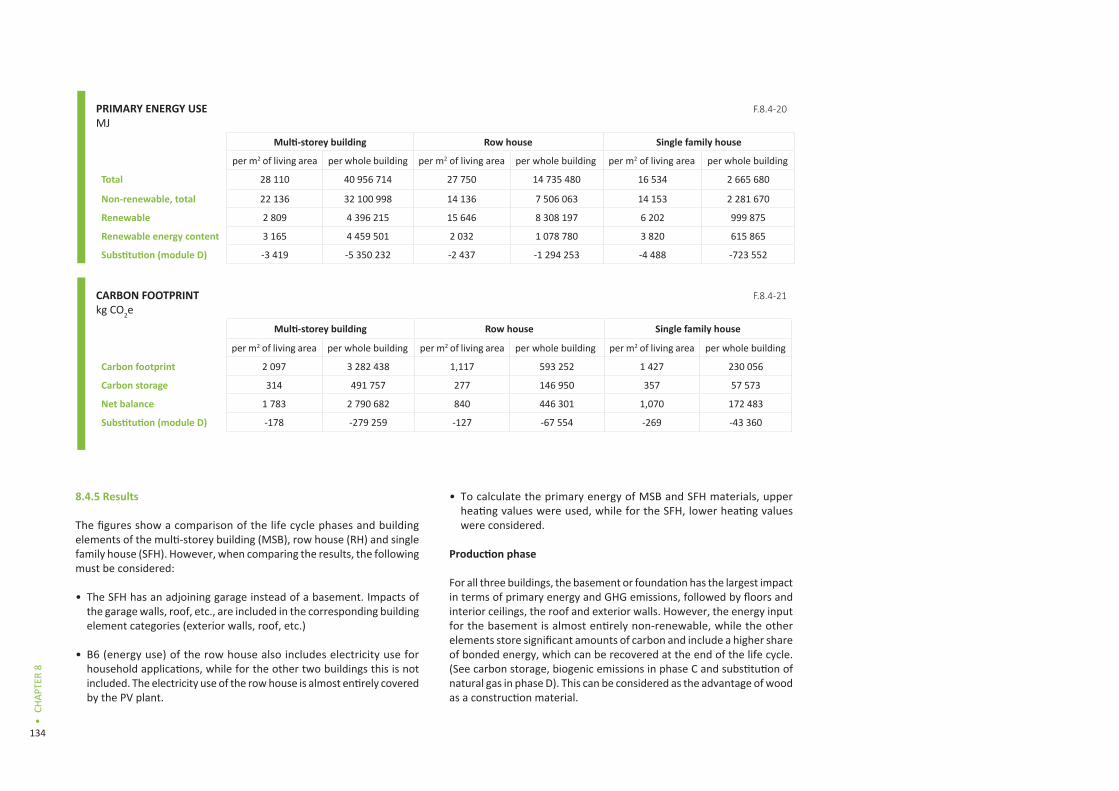
134
CHAP
TER
8
•
8.4.5 Results
The figures show a comparison of the life cycle phases and building elements of the multi-storey building (MSB), row house (RH) and single family house (SFH). However, when comparing the results, the following must be considered:
• The SFH has an adjoining garage instead of a basement. Impacts of the garage walls, roof, etc., are included in the corresponding building element categories (exterior walls, roof, etc.)
• B6 (energy use) of the row house also includes electricity use for household applications, while for the other two buildings this is not included. The electricity use of the row house is almost entirely covered by the PV plant.
• To calculate the primary energy of MSB and SFH materials, upper heating values were used, while for the SFH, lower heating values were considered.
Production phase
For all three buildings, the basement or foundation has the largest impact in terms of primary energy and GHG emissions, followed by floors and interior ceilings, the roof and exterior walls. However, the energy input for the basement is almost entirely non-renewable, while the other elements store significant amounts of carbon and include a higher share of bonded energy, which can be recovered at the end of the life cycle. (See carbon storage, biogenic emissions in phase C and substitution of natural gas in phase D). This can be considered as the advantage of wood as a construction material.
PRIMARY ENERGY USEMJ
Multi-storey building Row house Single family house
per m2 of living area per whole building per m2 of living area per whole building per m2 of living area per whole building
Total 28 110 40 956 714 27 750 14 735 480 16 534 2 665 680
Non-renewable, total 22 136 32 100 998 14 136 7 506 063 14 153 2 281 670
Renewable 2 809 4 396 215 15 646 8 308 197 6 202 999 875
Renewable energy content 3 165 4 459 501 2 032 1 078 780 3 820 615 865
Substitution (module D) -3 419 -5 350 232 -2 437 -1 294 253 -4 488 -723 552
CARBON FOOTPRINTkg CO2e
Multi-storey building Row house Single family house
per m2 of living area per whole building per m2 of living area per whole building per m2 of living area per whole building
Carbon footprint 2 097 3 282 438 1,117 593 252 1 427 230 056
Carbon storage 314 491 757 277 146 950 357 57 573
Net balance 1 783 2 790 682 840 446 301 1,070 172 483
Substitution (module D) -178 -279 259 -127 -67 554 -269 -43 360
F.8.4-20
F.8.4-21
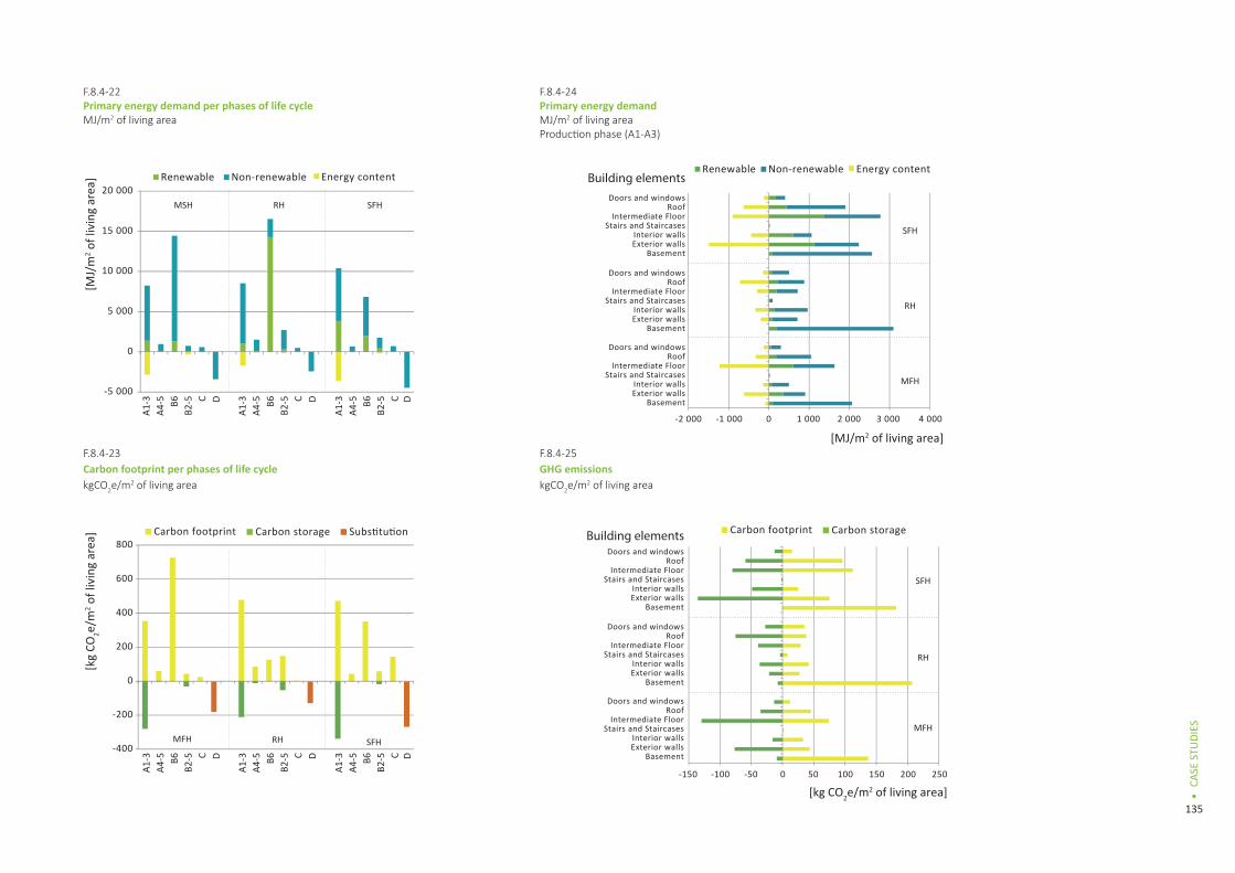
135
CASE
STU
DIES
•
-5 000
0
5 000
10 000
15 000
20 000MSH
A1-3
A4-5 B6
B2-5 C D
A1-3
A4-5 B6
B2-5 C D
A1-3
A4-5 B6
B2-5 C D
A1-3
A4-5 B6
B2-5 C D
A1-3
A4-5 B6
B2-5 C D
A1-3
A4-5 B6
B2-5 C D
RH SFH
-2 000 -1 000 1 000 2 000 3 000 4 0000
-150 -100 -50 50 150100 200 2500
BasementExterior wallsInterior walls
Stairs and StaircasesIntermediate Floor
RoofDoors and windows
BasementExterior wallsInterior walls
Stairs and StaircasesIntermediate Floor
RoofDoors and windows
BasementExterior wallsInterior walls
Stairs and StaircasesIntermediate Floor
RoofDoors and windows
BasementExterior wallsInterior walls
Stairs and StaircasesIntermediate Floor
RoofDoors and windows
BasementExterior wallsInterior walls
Stairs and StaircasesIntermediate Floor
RoofDoors and windows
BasementExterior wallsInterior walls
Stairs and StaircasesIntermediate Floor
RoofDoors and windows
Renewable Non-renewable Energy content
[MJ/m2 of living area]
Building elements
Building elements
Renewable Non-renewable Energy content
[MJ/
m2 o
f liv
ing
area
]
MFH
RH
SFH
-400
-200
0
200
400
600
800
MFH RH
SFH
[kg CO2e/m2 of living area]
[kg
CO2e/
m2 o
f liv
ing
area
] Carbon footprint Carbon storage Carbon footprint Carbon storageSubstitution
MFH
RH
SFH
F.8.4-22Primary energy demand per phases of life cycleMJ/m2 of living area
F.8.4-24Primary energy demand MJ/m2 of living areaProduction phase (A1-A3)
F.8.4-23Carbon footprint per phases of life cyclekgCO2e/m2 of living area
F.8.4-25GHG emissions kgCO2e/m2 of living area

136
CHAP
TER
8
•
Generally more carbon is stored in the massive wooden constructions of the MSB and the SFH than in the wooden frame structures of the RH. In all three buildings, the non-renewable primary energy use and the GHG emissions caused by the walls and roof are increased due to the use of mineral or glass wool and polystyrene as insulation materials. This is especially important for the wooden frame structures since the cavities are filled with glass wool. Alternative insulation materials like cellulose fibres could improve these indicators.
Building service installations are not significant in case of the MSB (gas and solar heating, central ventilation system) and the SFH (heat pump, central ventilation system). In case of the row house, the PV plant (consisting of a 151 m² collector, inverter, electric installations and fastening system for the roof) has an impact of almost 30% of the total primary energy input in the production phase. However, so far there is little data available for building service installations and their ancillary materials. Therefore results are subject to large uncertainties. More reliable information on building service installations could significantly improve knowledge about the impact of that part of the building’s life cycle.
When comparing the building concepts of a multi-storey building, row house, and single family house in terms of primary energy demand per m² in the production (and also maintenance) phase, it is obvious that the dense concept of MSBs is the most efficient one.
Maintenance phase
Due to the assumption of a 50-year service life, the replacement of materials covered in phase B4 is not very significant. This is due to the assumption that only windows, outside sealing and surface coverings, floor covering and HVAC get replaced once in this period. For all other materials and elements an assumed service life of 50 years and longer is foreseen.
Maintenance is therefore most significant for the row house as the energy intensive produced PV plant is exchanged once within the 50-year period.
An assumed service life of 100 years significantly increases the primary energy input and GHG emissions for phase B2-5 to a higher level than the production phase (A1-A3). In that case, the production and maintenance phase together may become more important than the energy use of the building. This is a strong
indicator that building materials have to be a focus of energy efficient building concepts in the future.
Energy use
The three buildings are equipped with different building service systems. This has a significant impact on phase B6 (energy use) of the life cycle. The MSB is equipped with a central gas boiler and a solar thermal system, which reduces the demand for gas. Nevertheless the non-renewable primary energy demand is quite high compared to the other buildings. The SFH is heated by a heat pump. The electricity mix is the European UCTE mix.
The row house has been designed as a Nearly Zero Energy Building (NZEB) according to Austrian definitions. The PV plant has therefore been designed to cover most of the non-renewable primary energy demand of the building for heating, ventilation and household appliances. Nevertheless the total primary energy demand (largely renewable from pellets) for heating and sanitary hot water production is quite high compared to the other buildings. This is due to the seasonal efficiency of the small scale pellet boilers used for heating and sanitary hot water production. On the contrary, GHG emissions in phase B6 are significantly lower
0
2000
4000
6000
8000
10000
12000
MFB RH SFH
Doors and windows
Roof-Ceiling
Floor-Ceiling
Stairs and Staircases
Interior walls
Exterior walls
Basement
[MJ/
func
tiona
l uni
t]F.8.4-26Primary energy demand MJ/m2 of living areaProduction phase A1-3

137
CASE
STU
DIES
•
for the row house. This again adds to the future importance of building materials and construction methods (represented in phases A1-3 and B2-5).
8.4.6 General assumptions for Austrian buildings
Assessment
For Austria the life cycle of three buildings (multi-storey house, row house, and single family house) has been assessed. The assessment is based on a mass balance according to the construction details and a generic data set (see “data”). The building data are gathered from the permission drawing, construction catalogue and energy calculation. Gross area was used as a measurement for exterior construction details, net area for inner walls and ceilings.
The assessment of the buildings is divided into the life cycle phases A to D according to EN 15978.
The data of the materials are aggregated from cradle to gate (A1-A3) and include all processes from extraction of raw materials to manufacturing of the product.
Transport from factory gate to site (A4) is carried out by lorry (28 tons), and distances depend on materials and products considering average transport distances of building products in Austria. For the construction process of the building on site (A5) only digging, evacuation of excavation material and refilling with gravel was considered. The amount of material losses was calculated according to Takano (2011). The manufacturing of materials substituting the losses was assigned to life cycle phase A5 and the corresponding transportation needs to A4.
The energy demand for heating and warm water use in the use phase (B6) was calculated according to the Austrian energy performance certificate for buildings.
Replacement of building products (B4) was considered; all other B phases (maintenance, repair and refurbishment) were disregarded. Service life depends on material, but mainly on the function of the product, the environmental and socio-economic conditions. In
the study at hand, the used reference service life for the materials follows a very simple concept, depending on the function of the product:
• Load carrying construction: 100 years
• Windows, outside sealing and surface coverings, floor covering, HVAC: 25 years
• All other materials: 50 years
Deconstruction and transport from site to waste treatment (C) is taken into account and depends on the material.
For module D (benefits and loads outside the system boundary), a typical scenario for the Austrian situation of waste wood treatment is applied. Waste wood is burned in an industrial waste co-incineration plant (for heat) with an efficiency of 90%. This amount of energy is substituted by gas, considering a boiler efficiency of 95%.
Primary energy is calculated using the higher heating value. The GWP is calculated according to IPCC 2007, all other LCIA indicators (not published here) according to CML 2001 v1.05. The calculations have been carried out using ECOSOFT v3.4.2 software.
Data
For all relevant processes (building materials, transportation and energy systems as well as for disposal processes) the IBO database 2008 (updated version Oct. 2010) was used.
System boundaries of the generic data for materials are cradle to gate (A1-A3). Basic data for standard processes such as energy systems, transport systems, basic materials, forestry, disposal processes, and packaging materials are obtained from Ecoinvent data v2.1. Some additional generic data for raw materials and intermediate products have been established by IBO in the course of product assessments and research projects. All data use the UCTE mix from Ecoinvent data v2.1 as electricity source, independent of the actual electricity source. Thermal processes are also modelled
with European modules from Ecoinvent. Biogenic CO2 emissions are considered to be carbon-neutral by Ecoinvent and are therefore not included in phases A and B. They can only be shown in phase C of the life cycle. In case allocation cannot be avoided, economic allocation is chosen. More details on the assessment methods can be found in IBO (2009).
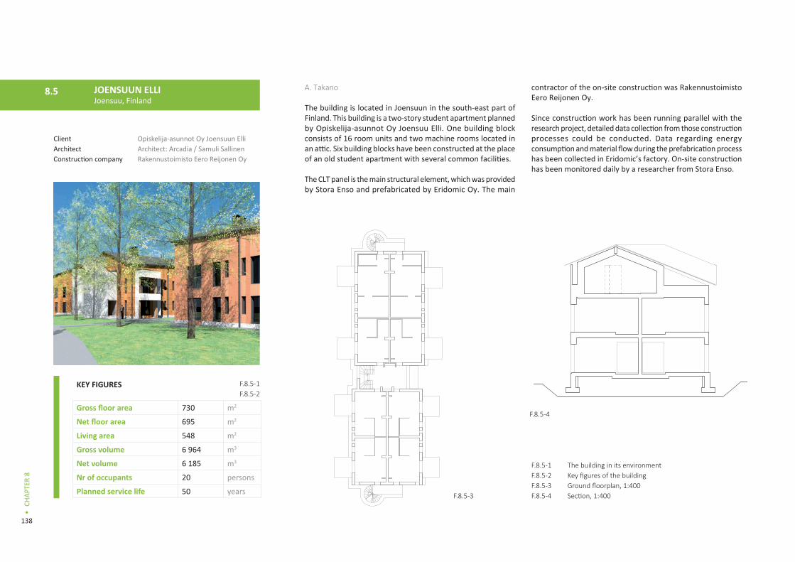
138
CHAP
TER
8
•
A. Takano
The building is located in Joensuun in the south-east part of Finland. This building is a two-story student apartment planned by Opiskelija-asunnot Oy Joensuu Elli. One building block consists of 16 room units and two machine rooms located in an attic. Six building blocks have been constructed at the place of an old student apartment with several common facilities.
The CLT panel is the main structural element, which was provided by Stora Enso and prefabricated by Eridomic Oy. The main
contractor of the on-site construction was Rakennustoimisto Eero Reijonen Oy.
Since construction work has been running parallel with the research project, detailed data collection from those construction processes could be conducted. Data regarding energy consumption and material flow during the prefabrication process has been collected in Eridomic’s factory. On-site construction has been monitored daily by a researcher from Stora Enso.
F.8.5-1F.8.5-2F.8.5-3F.8.5-4
The building in its environmentKey figures of the buildingGround floorplan, 1:400Section, 1:400
JOENSUUN ELLIJoensuu, Finland
8.5
ClientArchitectConstruction company
Opiskelija-asunnot Oy Joensuun ElliArchitect: Arcadia / Samuli SallinenRakennustoimisto Eero Reijonen Oy
F.8.5-1F.8.5-2
F.8.5-4
F.8.5-3
KEY FIGURES
Gross floor area 730 m2
Net floor area 695 m2
Living area 548 m2
Gross volume 6 964 m3
Net volume 6 185 m3
Nr of occupants 20 persons
Planned service life 50 years

139
CASE
STU
DIES
•
Assessment
This study covers the product stage, construction stage, and use stage (only operational energy use) of one building block (module A1-5 and B6). Detailed data collection has been conducted for both off-site and on-site construction works. All calculation was conducted manually with the help of templates created in this project. In addition, the energy content of wooden materials was calculated with an equation mentioned in the Ecoinvent database documentation/1/. The carbon storage capacity of wooden material was also calculated according to the standard (CEN/TC175 WI00175146).
Module A
All information regarding building components was collected from the detail drawings. The calculated mass of each component was cross-checked with the material order list provided by Eridomic Oy. The building service, furniture, and landscape around the building are excluded from the assessment due to lack of information.
Regarding the construction process, the prefabrication of wooden building elements, on-site earthwork, concrete foundation making, and assembly of the prefabricated building elements were covered based on the monitoring of construction work and interview with the constructor. Interior finishing, roof water proofing work,
building service installation, and assembly of the balcony were excluded from the assessment because of the time schedule and lack of data. For the prefabrication process, included inventories are electricity for the operation of the factory (machinery, lighting, ventilation) and space heating energy generated by a biomass boiler in the factory. For on-site work, included inventories are electricity for operation of the construction infrastructure and machine, and diesel for the construction machine. Transportation of building component and element were included according to the real situation. Waste from the prefabrication factory and construction site was also taken into account. Workers commuting to the factory or construction site were not covered.
Module B6
Operational energy use was assumed, based on the result of the calculation for the building permission, as 31,88 kWh/m2 per year for district heating and 26,75 kWh/m2 per year for electricity use. It is assumed that district heating energy and electricity are fully provided by the CHP plant. The energy mix was estimated based on the situation of the CHP plant in Joensuu and the national average value: 50% biomass, 17% natural gas, 9% coal, 18% peat, and 3% oil and waste incineration (Energiateollisuus 2013, Fortum 2013).
Data
ecoinvent ver. 2.2 was used in all calculation. (See Section 8.3 – Mietraching case study.)
Structures and construction methods
Foundation
On top of the concrete footing, a sandwich panel (put EPS insulation between precast concrete panels) is set up as a foundation. The slab toward the ground consists of an EPS mat and a precast concrete panel on top of that. This is a typical composition of a foundation in Finland.
Floors
The intermediate floor consists of eight layers as shown in the section. This floor is like a hollow panel with a CLT slab panel, glulam beam, and OSB board. On top of the OSB, a concrete layer is cast for sound insulation. Plastic sheet flooring is installed directly on top of the concrete layer.
F.8.5-5Exterior view of the building
ENERGY PERFORMANCE F.8.5-6
Operative energy use32 332 kWh/a
59 kWh/m2/a
Heat generation District heating
Heat distribution Radiator
Energy generation -Air tightness -
Energy class A

140
CHAP
TER
8
•
3 5
1 87642
JOENSUUN ELLI
1 3 5 6 7
2 4
1 2 3
4 5 6 7
1 2 3 4
External walls
The exterior wall consists of six layers as shown in the section. The U-value is 0,14 W/m2K. The insulation layer is divided into two layers, and just one layer has a wood stud in order to minimize cold-bridge via stud.
Roof
The roof element is composed of four layers as shown in the section. Basically the attic is ventilated (open) except for the machine room. The U-value of roof is 0,07 W/m2K.
Other structural features
CLT is main structural element and glulam/LVL beam is used for the floor and roof element. The balcony made of a CLT panel is attached on the exterior wall.
Construction work
Prefabrication
All wooden building elements were basically prefabricated in a factory. A pre-cut CLT panel was delivered from Stora Enso’s
Austrian mill to Eridomic’s factory in Finland and assembled with the other materials. The prefabrication factory is located in Pälkane, about 400 km from the construction site. The prefabricated building elements were delivered by truck. Window and door are installed partly on-site. Wood waste from the prefabrication process is burned in a biomass boiler, and generated heat is utilized for space heating in the factory. Working hours for the prefabrication was recorded by the company, which helped the allocation of consumed energy.
On-site work
All phases from earth work to assembly of the building element were covered. Since there are six building blocks on the site, several construction works were always running at the same time. Therefore, materials were delivered for all blocks at the same time, and construction machines were shared by each block. In addition, there was a single electricity meter on the site for all construction and the infrastructure. This would be a typical situation in construction work, which makes data collection rather difficult and complex. However, in this case, the on-site construction work was monitored daily, so it could help to allocate the material and energy flow to each construction process to some extent.
Results
Primary energy balance
The material production stage, construction stage, and use stage account for approximately 40%, 10%, and 50% of the total primary energy consumption in module A and B6, respectively. The energy content in wooden materials is two times more than the energy consumption during construction work (A4-5). It is remarkable that the transport of construction material and equipment (A4) consumed about three times more energy than the actual construction work (A5), due to the very long transportation distance of the main structural material and prefabricated building element. CLT elements were delivered from Austria to Finland by truck and ferry, and prefabricated building elements were delivered for 400 km by 14 trucks. This long transport is the main energy consumer in module A4-5.
Primary energy consumption in module A and B6 is almost the same, even in a 50-year service life. This could be for two reasons. The first reason would be high energy performance of the building (see above), and the second would be the high ratio of biomass fuel in the energy mix of the CHP plant. As a result, more than half of the primary energy consumption in module B6 is renewable.
1. Gypsum board2. CLT board 120mm3. Thermal insulation 550mm4. LVL beams5. OSB board 18mm6. Bituminous felt7. Steel roofing
F.8.5-6Roof detail
F.8.5-8Base floor detail
F.8.5-7Wall detail
1. Exterior wood cladding2. Battens (vertical)3. Battens (horizontal)4. Wind barrier board (LDF)5. Mineral wool insulation 98mm6. Mineral wool insulation 125mm7. CLT board 100mm
1. Floor material2. Concrete slab 100mm3. EPS insulation 2x100mm4. Gravel
3 5
1 87642
JOENSUUN ELLI
1 3 5 6 7
2 4
1 2 3
4 5 6 7
1 2 3 4
3 5
1 87642
JOENSUUN ELLI
1 3 5 6 7
2 4
1 2 3
4 5 6 7
1 2 3 4

141
CASE
STU
DIES
•
Carbon footprint
The same trend could be seen as primary energy balance, approximately 50% of GHG emissions originate in the use stage (B6) and the other half in module A. The carbon storage capacity in wooden materials is almost the same as GHG emissions in module A1-5. As explained before, module A4 showed a larger carbon footprint than module A5 here as well.
Conclusions
The production stage of Joensuun Elli shows a similar result as the result of Mietraching. However, a totally different result can be seen in module B6. The actual energy demand for the building operation is also very similar, but a different energy mix for district heating and electricity makes a significant gap. GHG emission from the building operation becomes small when heat and electricity are provided from the CHP plant, and biomass fuel is used mainly in the plant. This comparison would indicate the importance of considering both the energy efficiency in a building life cycle and energy resources for carbon efficient wood construction.
F.8.5-9F.8.5-10F.8.5-11F.8.5-12
Carbon footprint resultsPrimary energy resultsCarbon footprint of different building elementsPrimary energy demand of different building elements
-200 -150 -100 -50 0 50 100 150
Basement
Exterior walls
Interior walls
Stairs and Staircases
Floor-Ceiling
Roof-Ceiling
Doors and windows
-2 000 -1 000 0 1 000 2 000
Basement
Exterior walls
Interior walls
Stairs and Staircases
Floor-Ceiling
Roof-Ceiling
Doors and windows
[kg CO2e/m2 of living area]
[MJ/m2 of living area]
Fossil Carbon storageBuilding elements
Building elements Renewable Non-renewable Energy content
CARBON FOOTPRINT (A1-5, B6)kgCO2e
per m2 of living area per whole building
Carbon footprint 1 000 548 151
Carbon storage - 433 - 237 484
Net balance 567 310 667
per m2 of living area per whole building
Total 21 917 12 010 853
Renewable 8 730 4 784 339
Non-renewable 13 187 7 226 514
Energy content - 4 151 38 - 2 274 958
PRIMARY ENERGY USE (A1-5, B6)MJ
F.8.5-9 F.8.5-10
F.8.5-12F.8.5-11

142
CHAP
TER
8
•
M. Kuittinen
The Tervakukka house is located in Tampere, in the middle Finland. It belongs to an area that was built for the annual housing fair 2012. This passive house was designed in cooperation with several stakeholders, with a common goal: to implement principles of “eco-functionality” in practice. The concept of eco-functionality has been developed in an earlier research project by the Work Efficiency Institute in Finland (TTS). It describes the interdependence of the functionality and environmental loads of a home.
The design team included experts in accessibility, ergonomics, building services, gardening and sustainability. The design work was steered by the client family and the Finnish Association for Nature Conservation (SLL).
The building is a single family home in a suburban district of Tampere, the third largest city in Finland. Its common areas are located downstairs, where also a spacious sauna department is built. The bedrooms and a home office are placed upstairs. A private balcony is placed between the main building and garage so that sunbaths can be taken without compromising privacy in the densely built neighbourhood.
All toilets and bathrooms are placed close to the technical space, in order to reduce the length of pipes. The building is heated with a hybrid solution that consists of electric floor
heating, electric air heating, wood heating (a fireplace), solar collectors and ventilation with an integrated heat pump and heat recovery. Summertime cooling is assisted with underground pipes, through which air is pre-cooled. Solar collectors were mounted on a southern wall, so that they would give energy during the winter months, when sun is very low. Wall-mounting also prevents them from being covered with snow. The family wanted to have a Jacuzzi but were concerned about its energy demand. As a solution, the water for a Jacuzzi is heated in a fireplace that has built-in heat transfer pipes.
The constructor of the house was GreenBuild, a Finnish company that makes wooden passive houses with recycled cellulose insulation.
Assessment
The aim was to study the greenhouse gas emissions and primary energy demand from the production phase (A1-3) and the operative energy use (B6) of a passive house. The energy content of wooden materials was also estimated (D). Furthermore, two alternative construction systems were compared: timber frame with cellulose insulation and aircrete block frame with EPS insulation. Both designs had the same U-values and energy efficiency.
TERVAKUKKA PASSIVE HOUSETampere, Finland, 2012
8.6
F.8.6-1F.8.6-2F.8.6-3
Exterior view of the houseKey figures of the buildingFloor plans, 1.200
ClientArchitect
Construction company
PrivateKombi Arkkitehdit Oy Matti Kuittinen, Julia BilenkoGreenBuild Oy
F.8.5-1
F.8.5-2
F.8.5-3
KEY FIGURES
Gross floor area 258 m2
Net floor area 198 m2
Living area 198 m2
Gross volume 1 036 m3
Net volume 567 m3
Nr of occupants 4 persons
Planned service life 100 years

143
CASE
STU
DIES
•
Basement floor detail
Intermediate floor detail
Roof detail Wall detail
1 3 6 85
742
1
34
2
6
7
4
5
12
45
3
31 2
8
3
Basement floor detail
Intermediate floor detail
Roof detail Wall detail
1 3 6 85
742
1
34
2
6
7
4
5
12
45
3
31 2
8
3
Basement floor detail
Intermediate floor detail
Roof detail Wall detail
1 3 6 85
742
1
34
2
6
7
4
5
12
45
3
31 2
8
3
External wall (timber version)
1. Spruce cladding 28mm2. Horizontal battens 25x1003. Vertical battens 25x1004. Wind barrier board LDF 25mm5. Cellulose insulation 400mm >50kg/m3
6. Vapour barrier textile7. Plywood
Base floor
1. Gravel 300mm2. EPS insulation 200mm3. Concrete slab 80 mm4. Floor surface
Roof
1. Metal roofing2. Battens 22mm3. Condensation barrier textile4. Ventilation gap battens 120mm5. Gypsum board6. Roof trusses and cellulose insulation 600mm7. Air barrier textile8. Gypsum board
The point of the assessment was the “as designed” stage, as accurate information from the construction site was not available.
Normative standards EN 15978 and ISO/TS 14067 were used as reference in the gathering and documentation of results.
The inventory was carried out from working drawings of the architect and structural engineer. The system boundary included the main structural elements and interior and exterior surfaces. An inventory for building services, white goods, furniture and gardening was not carried out, due to lack of data. The accuracy of the inventory includes used materials as designed and joinery with fixing materials as designed. Site energy use or waste was not assessed. Furthermore, temporary materials (for example, scaffolding and weather protection) and energy use for construction work or transportation were not assessed.
Operative energy use was estimated from the energy calculation of the building. There was a special use of green electricity for heating and operations. In Finland, a labelling scheme for green electricity has been developed by the Finnish Association for Nature Conservation. This “EKOenergy” scheme was approved to be expanded to other parts of Europe as well, after 23 nature conservation organisations from 18 countries agreed to support it. The label can be given to power companies that use only renewable energy and invest a certain share of income in building additional capacity for renewal energy. Therefore the greenhouse gas emissions from the use phase electricity are zero. This feature underlines the importance of controlling the emissions from the production phase.
An impact assessment was carried out by using GWP (global warming potential) and PE (primary energy) indicators from the selected database.
Data
The data source was ecoinvent version 2.2. The system boundary for data was cradle-to-gate (A1-3). EPDs (Environmental Product Declarations) could not be used, since they were not available for the majority of the used construction products. For consistency of data, we chose to use same the database for all products.
Structures and construction methods
The house was built on-site. Its structural system is balloon frame.
Foundation and floors
A slab-to-ground structure is used for the base floor. It is made from concrete and EPS insulation. The foundation is built with hollow EPS blocks (Soklex), which are filled with concrete cast on-site. Piling was required because of soft soil. In addition, a significant landfill of around 2 metres was required by city. All neighbouring site levels were equally raised, so that sewage pipe levels would better fit the areal collective sewage pipe level without pumping.
The intermediate floor was built on-site with wooden I-joists made of massive timber and HDF. The intermediate floor cavity was filled with cellulose insulation for sound insulation.
F.8.6-4F.8.6-5F.8.5-6
Roof detailWall detailBase floor detail

144
CHAP
TER
8
•
External walls
The load-bearing wall studs are made from I-joists. Insulation is cellulose fibre that was wet-sprayed into wall cavities. An air-barrier layer is made from textile that is placed inside the insulation layer.
External cladding was built from spruce planks that were painted black with a traditional mixture of tar and linseed oil. Parts of cladding were realised from white cement fibre boards that had CNC-engraved ornaments on them.
Roof
The roof structure was made from nail trusses and supporting glulam and LVL beams. The shape of trusses was parallel to the roof. Cellulose insulation was sprayed into the cavities. Ventilation pipes could be left without insulation because they were placed in a warm area between the insulation layer and the lowered ceilings. The roof cover is painted steel. The colour of the roof was light grey because it reflects sunlight back into space and thus has a symbolic effect on global warming.
Other structural features
Internal walls were made from sawn massive wooden studs. Wooden panels and wallpaper with gypsum board were used for their cladding. Internal stairs were made of wood and safety glass. External terraces were built from impregnated wood.
Alternative design
The alternative design was based on aircrete blocks and EPS insulation. Only the external walls and intermediate floors were changed. The roof, base floor and foundation were the same in both designs.
External walls were made from internal gypsum board, 250mm aircrete blocks, 170mm EPS insulation and 30mm external rendering.
Intermediate floors were designed from reinforced aircrete slabs. Ceilings were rendered. Floors were comparable to the timber-framed design.
Construction work
The Tervakukka house was built on-site during the winter of 2011-2012. Weather conditions were humid because the autumn of 2011 was the warmest ever recorded in Finland. Extreme weather also caused accidents; a spruce tree fell over the half-finished building and parts of the partially finished wall structure had to be replaced.
Results
Primary energy demand
The aircrete version of the building had in total around a 30% higher primary energy demand for production of materials. This figure applies to the whole building. But for external walls and intermediate floors, the difference is considerably higher.
In the timber-framed version, most of the energy goes into the production of non-wooden materials for the foundation and the floor slab. In addition to concrete, the EPS insulation especially seems to be very energy intensive.
Carbon footprint
Only fossil greenhouse gas emissions were taken along in the impact assessment. In addition, carbon storage in wood products was included in the figures. Because the use electricity is carbon-neutral, the dominant part of the carbon footprint is caused by the production of building materials.
The aircrete version of the building had in total around a 40% higher carbon footprint as the timber-framed version. Again, if we look at external walls and intermediate floors, this difference was more dramatic.
CARBON FOOTPRINT (A1-3) F.8.6-8kgCO2e
per m2 of living area per whole building
Carbon footprint 407,06 80 597,15
Carbon storage -258,63 -51 209,72
Net balance 148,42 29 387,43
per m2 of living area per whole building
Total 8 978,93 1 777 828,93
Renewable 766,23 151 712,81
Non-renewable 8 212,71 1 626 116,12
Energy content -2 129,30 -421 601,63
PRIMARY ENERGY USE (A1-3) F.8.6-9MJ
ENERGY PERFORMANCE F.8.6-7
Operative energy use25 377 kWh/a
128 kWh/m2/a
Heat generation Hybrid (electricity, solar, wood)
Heat distribution Electric floor heating, air heating
Energy generation Wood, solar
Air tightness 0,6 h-1
Energy class Passive house
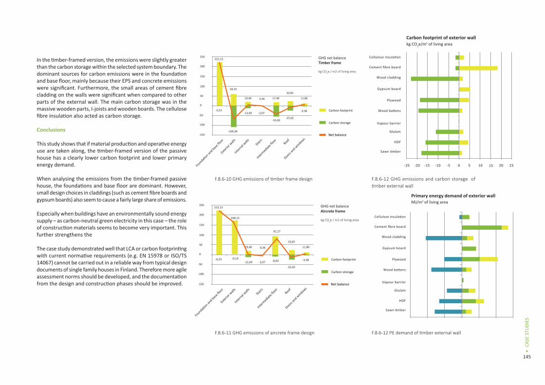
145
CASE
STU
DIES
•
In the timber-framed version, the emissions were slightly greater than the carbon storage within the selected system boundary. The dominant sources for carbon emissions were in the foundation and base floor, mainly because their EPS and concrete emissions were significant. Furthermore, the small areas of cement fibre cladding on the walls were significant when compared to other parts of the external wall. The main carbon storage was in the massive wooden parts, I-joists and wooden boards. The cellulose fibre insulation also acted as carbon storage.
Conclusions
This study shows that if material production and operative energy use are taken along, the timber-framed version of the passive house has a clearly lower carbon footprint and lower primary energy demand.
When analysing the emissions from the timber-framed passive house, the foundations and base floor are dominant. However, small design choices in claddings (such as cement fibre boards and gypsum boards) also seem to cause a fairly large share of emissions.
Especially when buildings have an environmentally sound energy supply – as carbon-neutral green electricity in this case – the role of construction materials seems to become very important. This further strengthens the
The case study demonstrated well that LCA or carbon footprinting with current normative requirements (e.g. EN 15978 or ISO/TS 14067) cannot be carried out in a reliable way from typical design documents of single family houses in Finland. Therefore more agile assessment norms should be developed, and the documentation from the design and construction phases should be improved.
Net balance
Carbon footprint
Carbon storage
Roof
Doors an
d windows
Intermediat
e floorSta
irs
Internal wall
s
Exterio
r wall
s
Foundati
on and base
floor
223,13
-0,53
59,33
-109,39
-12,69
19,40 0,36
-2,07
17,49
-55,83
23,05
-25,02
-3,38
11,80
250
200
150
100
50
0
-50
-100
-150
GHG net balanceTimber frame
kg CO2e / m2 of living area
-25 -20 -15 -10 0 5 10 15
Vapour barrier
Wood battens
Plywood
Gypsum board
Wood cladding
Cement fibre board
kg CO2e/m2 of living areaCarbon footprint of exterior wall
Carbon footprint Carbon storage
Glulam
HDF
Sawn timber
Cellulose insulation
20 25-5
-300 -200 -100 0 100
Vapour barrier
Wood battens
Plywood
Gypsum board
Wood cladding
Cement fibre board
MJ/m2 of living areaPrimary energy demand of exterior wall
Renewable Non-renewable
Glulam
HDF
Sawn timber
Cellulose insulation
200 300
Energy content
F.8.6-10 GHG emissions of timber frame design F.8.6-12 GHG emissions and carbon storage of timber external wall
F.8.6-12 PE demand of timber external wallF.8.6-11 GHG emissions of aircrete frame design
Net balance
Carbon footprint
Carbon storage
Roof
Doors an
d windows
Intermediat
e floorSta
irs
Internal wall
s
Exterio
r wall
s
Foundati
on and base
floor
223,13
-0,53
168,15
-12,69
19,40 0,36
-2,07
92,27
-8,83
23,05
-25,02
-3,38
11,80
250
200
150
100
50
0
-50
-100
-150
GHG net balanceAircrete frame
kg CO2e / m2 of living area
-0,13
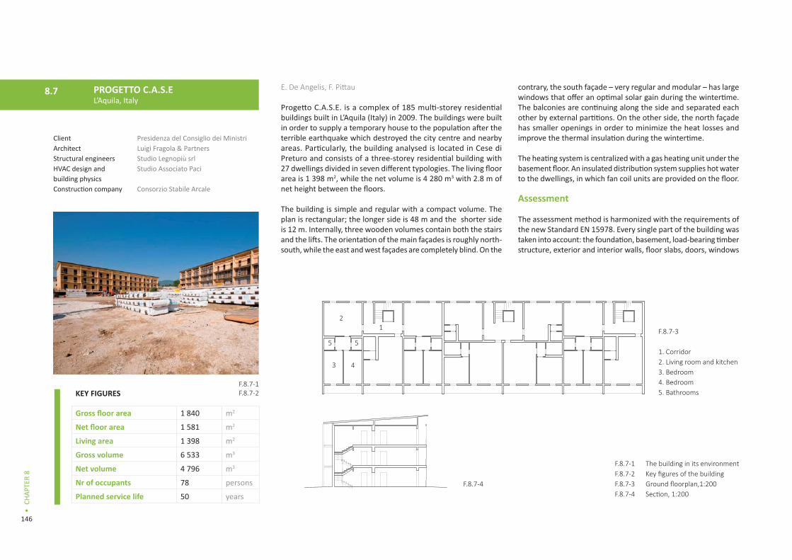
146
CHAP
TER
8
•
E. De Angelis, F. Pittau
Progetto C.A.S.E. is a complex of 185 multi-storey residential buildings built in L’Aquila (Italy) in 2009. The buildings were built in order to supply a temporary house to the population after the terrible earthquake which destroyed the city centre and nearby areas. Particularly, the building analysed is located in Cese di Preturo and consists of a three-storey residential building with 27 dwellings divided in seven different typologies. The living floor area is 1 398 m2, while the net volume is 4 280 m3 with 2.8 m of net height between the floors.
The building is simple and regular with a compact volume. The plan is rectangular; the longer side is 48 m and the shorter side is 12 m. Internally, three wooden volumes contain both the stairs and the lifts. The orientation of the main façades is roughly north-south, while the east and west façades are completely blind. On the
contrary, the south façade – very regular and modular – has large windows that offer an optimal solar gain during the wintertime. The balconies are continuing along the side and separated each other by external partitions. On the other side, the north façade has smaller openings in order to minimize the heat losses and improve the thermal insulation during the wintertime.
The heating system is centralized with a gas heating unit under the basement floor. An insulated distribution system supplies hot water to the dwellings, in which fan coil units are provided on the floor.
Assessment
The assessment method is harmonized with the requirements of the new Standard EN 15978. Every single part of the building was taken into account: the foundation, basement, load-bearing timber structure, exterior and interior walls, floor slabs, doors, windows
F.8.7-3
1. Corridor2. Living room and kitchen3. Bedroom4. Bedroom5. Bathrooms
12
3
5 5
4
F.8.7-1F.8.7-2F.8.7-3F.8.7-4
The building in its environmentKey figures of the buildingGround floorplan,1:200Section, 1:200
PROGETTO C.A.S.EL’Aquila, Italy
8.7
ClientArchitectStructural engineersHVAC design and building physicsConstruction company
Presidenza del Consiglio dei Ministri Luigi Fragola & PartnersStudio Legnopiù srlStudio Associato Paci
Consorzio Stabile Arcale
F.8.7-1F.8.7-2
F.8.7-4
KEY FIGURES
Gross floor area 1 840 m2
Net floor area 1 581 m2
Living area 1 398 m2
Gross volume 6 533 m3
Net volume 4 796 m3
Nr of occupants 78 persons
Planned service life 50 years

147
CASE
STU
DIES
•
and roof. All the stages of the life cycle of the building were considered for the different building parts, while only the impacts due to the production of materials (mod. A1-3) were considered for the evaluation of the building services and installations. In the use and maintenance phase (mod. B), the total share of GHG emissions was estimated on the base of the related primary energy consumption for heating and the presumed yearly operational energy use. In addition, the GHG emissions for maintenance were estimated taken into account only the required energy for the substitution of the damaged elements at the end of the assumed reference service life. Finally, for the evaluation of the end-of-life phase (mod. C) a single scenario was considered, assuming that all the wooden parts were brought to incineration after their service life, while the non-wooden material was taken to landfill. No evaluation of the benefits beyond the system boundaries (mod. D) was carried out.
GHG emissions from bio-fuels were assumed as net-zero, considering that all the round wood needed came from environmentally managed forests. According to EN 16449, a rate of 50% of carbon per mass of dry wood was considered for the calculation of the carbon content in timber mass. Any consideration of future changes in energy mixes in the production of electricity and
district heat was not assumed due to uncertainties in data and in future scenarios.
Data
Data from the ecoinvent 2.2 database was adopted in the LCIA of building materials, as well as for the carbon emission and energy consumption of transportation from gate to site (A4). The age of the data collected for each material and process is less than two years. No specific EPDs regarding the used materials in the building parts were available. For the evaluation of the energy content, the net calorific value was considered.
The quality of data for emissions from combustion of fuels is affected by the assumed mean efficiency of burning/incineration. The specific values of carbon emission per unit of primary energy provided were assumed per each fuel source, and the IPCC method considered for the calculation of CO2e emissions. For the LCI of material, the actual Italian conditions were considered; in particular, the use of national average values for electricity, the distances for transport of products and the mean specific national emissions from electricity production in a power plant. No specific data of the waste management were available in the
Structural layers:
1. External cement fibre boards 15mm2. Ventilation gap 40mm3. Wind barrier sheet4. Cork insulation panels 30mm5. CLT panels 110mm6. Mineral wool insulation 110 mm7. Zinc coated steel profiles8. Internal gypsum plaster boards 25mm
Structural layers:
1. Solid wood parquet flooring2. Anhydrated gypsum boards3. EPS panels 140mm4. Levelling mortar 50mm5. Reinfroced concrete slab 500mm
3 5
1 2 4 6 7 8
4
5
321
1 3 5 6 8
2 4 71 2 3
54
3 5
1 2 4 6 7 8
4
5
321
1 3 5 6 8
2 4 71 2 3
54
3 5
1 2 4 6 7 8
4
5
321
1 3 5 6 8
2 4 71 2 3
54
F.8.7-5F.8.7-6F.8.7-7F.8.7-8
F.8.7-8
F.8.7-7
Facade detail of the buildingRoof detail, 1:10Wall detail, 1:10Base floor detail, 1:10
F.8.7-5 F.8.7-6
Structural layers:
1. Bituminen aluminium ceiling2. CLT panels3. Ventilation air gap4. Rockwool 160mm5. CLT panels

148
CHAP
TER
8
•
on-site construction phase. For this reason, general data from the literature were taken into account.
The energy needs for heating were calculated through a steady-state simulation based on the Italian energy standard. The building is not monitored, therefore the real amount of primary energy consumed year by year is difficult to clearly estimate. For this reason, an average value of the annual energy consumption of a standard Italian family was considered for the evaluation of the operational energy and related carbon emission.
Structures and construction methods
The structure is completely made of CLT panels, except for the basement, which is made of concrete. Timber panels 11 cm thick were used for walls, while panels 18 cm thick were used for floors and the roof, which is ventilated and not insulated. A 16-cm insulation layer of fibre wood was placed in the upper floor, with a cross ventilation which ensures the best hygrothermal conditions during the summer.
Foundation and floors
The foundation is completely made of concrete, with a slab 50 cm thick on the ground and an upper basement 50 cm thick, insulated with 14 cm of EPS. The basement is supported by reinforced concrete columns 80x80 cm.
The internal floors are made of 18 cm CLT panels, with 4 cm mineral wool, a double layer of gypsum fibreboards, 3 cm chipboard and wooden flooring. The upper floor is insulated with 16 cm fibre wood.
External walls
The external walls consist of an internal part in a metallic light structure, insulated with 5 cm mineral wool, on which the plasterboard is fixed. On the other side, a continuous insulation layer of cork is fixed with glue on CLT panels. The external cladding is made of grey cement fibreboard fixed on spruce battens, which create a ventilated air gap.
Roof
The sloping roof is made of two layers: the structural part in CLT panels and the waterproof sheet.
Other structural features
Special seismic isolators (metallic sliding pendulum isolators) are placed between each concrete column and the basement in order to guarantee the proper seismic insulation of the timber structure from the ground.
Construction work
After the realization of the concrete basement, the building was mainly assembled on-site. In a few days, the timber structure was built up and in less than 3 months all the components were rapidly assembled.
Prefabrication
The prefabrication level of the structure is not very high. Overall, the process consisted of cutting and drilling the CLT panels, as well as in fixing the metallic connections to the different supports. All the other parts of the building (insulation, claddings, windows, service installations, etc.) were installed on-site, except fot the bath cells, which were fully prefabricated and assembled on-site.
F.8.7-9F.8.7-10
Fossil greenhouse gas emissions for the different building elementsPrimary energy demand for the different building elementsF.8.7-9 F.8.7-10
[kg CO2e/m2 of living area]
-2 000 0 2 000 4 000 6 000
Basement
Exterior walls
Interior walls
Stairs and Staircases
Floor-Ceiling
Roof-Ceiling
Doors and windows
Basement
-300 -200 -100 0 100 200 300 400 500
Exterior walls
Interior walls
Stairs and Staircases
Floor-Ceiling
Roof-Ceiling
Doors and windows
Renewable Non-renewable Energy content
Fossil Carbon storage
[MJ/m2 of living area]
Building elements
Building elements

149
CASE
STU
DIES
•
CARBON FOOTPRINT (full life cycle) kgCO2e
per m2 of living area per whole building
Carbon footprint 2 271 3 175 135
Carbon storage - 580 - 811 492
Net balance 1 691 2 363 643
per m2 of living area per whole building
Total 36 441 50 945 059
Renewable 8 216 11 485 892
Non-renewable 28 225 39 459 167
Energy content - 5 781 - 8 082
PRIMARY ENERGY USE (full life cycle)
MJ
On-site work
Most of the activities during the construction phase were made on-site. The duration of the work was relatively short – only 72 days. In order to respect the constrained timing, the contractors were forced to work all day long, night included, with a relevant consumption of electricity for lighting.
Results
Primary energy balance
From the calculation over the whole building life cycle, the most relevant impact in terms of PE-nr is given by module B (use & maintenance), with a share of 42%. Following the A1-3 (production phase) accounts for a share of 39%, with a marginal share given by modules A4-5 (construction) and C (end of life). On the contrary, if the PE-r is considered, the most relevant impact is given by mod. A1-3 (86%). A marginal share is accounted by module B (12%) module C (1,3%) and finally by module A4-5 (0,7%). The building elements contribute to the overall energy consumption with a share of 80-85%. More than 60% of the PE-nr consumed is given by the basement.
Carbon footprint
Module B is responsible for the most fossil carbon emissions, with a share of 49%, followed by module A1-3 (35%) and a marginal share by modules A3-5 and C. Considering the biogenic carbon emissions instead, module C is the most relevant, with a share of 62%, followed by module A1-3 (27%), module B (7%) and finally module A4-5 (5%). The building elements are responsible for the most relevant GHG emissions, with a share of 81-84%. More than half of that impact is given by the basement.
Conclusions
On the base of the achieved results, some basic conclusions can be summarized here:
• The use phase plays a fundamental role in building the carbon footprint. The relative low thermal resistance of the envelope, if compared to the high performance of very low energy buildings, leads to a high score of fossil carbon emission for heating, which affects the results significantly. Maintenance has a modest dominance, affecting the results for a share of roughly 5%.
• The carbon emission given by building services and installations (heating machinery, water pipes, electricity, etc.) is very difficult to estimate. If specific EPDs are not available, only the relative share of GHG emissions due to the production of materials can be taken into account. However, the results show that their contribution is modest, roughly 1-2%.
• In the production and construction phase, a relevant share of GHG emissions and PE consumption is due to the realization of the foundations and basement. In order to ensure a more sustainable building environment, the influence of these parts, often almost completely ignored by architects and operators in the building sector, should be seriously considered during the design phase.
F.8.7-11F.8.7-12F.8.7-13
Energy performance of L’Aquila buildingCarbon footprint results for the full life cyclePrimary energy use results for the full life cycle
F.8.7-12 F.8.7-13ENERGY PERFORMANCE F.8.7-11
Operative energy use60 141 kWh/a
43,01 kWh/m2/a
Heat generation Gas condensing boiler
Heat distribution Fan coil units
Air tightness 0,4 h-1
Energy class B (Italian Energy Standard)

150
CHAP
TER
8
•
IncludedIncluded in partNot included
Covered parts of life cycle
Product stage A1 Raw material supply A2 Transport A3 ManufacturingConstruction process A4 Transport A5 Construction processUse stage B1 Use B2 Maintenance B3 Repair B4 Replacement B5 Refurbishment B6 Operational energy use B7 Operational water useEnd-of-life stage C1 Deconstruction C2 Transport C3 Waste processing for reuse, recovery and recycling C4 Disposal D Additional loads and benefits beyond the system boundary
Energy recovery from wooden residues can be a remarkable benefit for choosing wood for construction material.
Wood-framed passive houses with energy-efficient heat supply reduce climate impacts. Generally, massive wood construction systems result in the largest amounts of residues and bio-energy potential.
Site works and foundations seem to have a high impact on the carbon footprint and primary energy demand. Especially the use of concrete, re-bars and hard insulation boards cause emissions.
Emissions from construction work and transportation are very case-specific. The energy demand from construction work can vary highly depending on the outside temperature, because heating a half-finished building or pre-fabrication facilities seems to be very energy-consuming.
There will be a shift in the lifecycle carbon efficiency of buildings from the use phase to the production phase. This is because buildings require less energy for their operation.
The design phase does not typically give enough information for the carbon footprint or primary energy assessment that is required in standards (e.g. EN 15978). Therefore a more agile assessment scheme for enabling assessment in design phase would be needed.
Including all building service installations with their ancillary materials may be very time-consuming and include large uncertainties. Therefore it could be considered that building service information is left out of an assessment until it becomes better documented in the construction phase.
F.8.8-1F.8.8-2
F.8.8-1
Covered parts of life cycleCovered parts of building
Lessons learned8.8

151
CASE
STU
DIES
•
WÄL
LUDE
N
MIE
TRAC
HIN
G
MÜ
LHW
EG
STEI
NBR
ECHE
RGAS
SE
SCHÖ
NKI
RCHE
N
JOEN
SUU
N E
LLI
TERV
AKU
KKA
L’AQ
UIL
A Covered parts of building
Site worksGround worksPilingLandscaping (excluding plants)
Building elementsBasementExternal wallsInternal wallsStairs and staircasesIntermediate floorRoofDoors and windows
FurnitureBuilding related furnitureNon-building related furniture
Building services and machineryHeating machinery and installations Cooling machinery and installationsVentilation machine and ductsWater pipes and installationsSewage pipes and installationsElectricity installationsLightsAutomation, monitoring and security systemsWhite goodsElevators and excavators
ExternalBalconiesTerraces and other external building partsPaving Plants and vegetation
Temporary itemsScaffolding and elevatorsTemporary machinery and building servicesTemporary cabins for workersTemporary infrastructureTemporary ground worksOther (case-specific)
WÄL
LUDE
N
MIE
TRAC
HIN
G
MÜ
LHW
EG
STEI
NBR
ECHE
RGAS
SE
SCHÖ
NKI
RCHE
N
JOEN
SUU
N E
LLI
TERV
AKU
KKA
L’AQ
UIL
A
F.8.8-2

152
CHAP
TER
8
•
REFERENCES
8.2 Wälludden as a case study of three new wood building systems
BBR (Boverkets Byggregler). 2012. Boverkets Författningssamling (Building and Planning Regulations). The National Board of Housing, Building and Planning, Karlskrona, Sweden. (In Swedish).
Björklund T. and Tillman A-M., 1997. LCA of building frame structures: environmental impact over the life cycle of wooden and concrete frames. Technical Environmental Planning Report 1997:2. Chalmers University of Technology.
Dodoo, A., Gustavsson, L. and Sathre, R., 2009. Carbon implications for end-of-life management of building materials. Resources, Conservation and Recycling, 53(5): 276-286.
FEBY (Forum for Energieffektiva Byggnader), 2009. Kravspecification för passivhus, 2009. (In Swedish).
Gustavsson, L. and Karlsson Å., 2002. A system perspective on the heating of detached houses. Energy Policy, 30(7): 553-574.
Gustavsson, L., Joelsson, A., and Sathre, R. 2010. Life cycle primary energy use and carbon emission of an eight-story wood-framed apartment building. Energy and Buildings, 42(2): 230-242.
Gustavsson, L., Dodoo, A., Truong, N.L., and Danielski, I. 2011. Primary energy implications of end-use energy efficiency measures in district heated buildings. Energy and Buildings, 43 (1): 38-48
Gustavsson, L., Pingoud, K., and Sathre, R., 2006. CO2 balance of wood substitution: comparing concrete- and wood-framed buildings. Mitigation and Adaptation Strategies for Global Change, 11(3): 667-691.
Gustavsson L. and Sathre R., 2006. Variability in energy and CO2 balances of wood and concrete building materials. Building and Environment, 41(7): 940-951.
Karlsson Å., 2003. ENSYST, Lund: Lund University, Sweden.
Strusoft. 2010. Overview of VIP-Energy. Accessed at www.strusoft.com on June 13, 2011.
8.3 4 Holz Mietraching
AGFW Branchenreport 2006, by the German Heat and Power Association -AGFW- (in German).
8.4 Austrian buildings
Amtmann, M.; Gross, M., 2011. Austrian Building Typology– Eine Typologie österreichischer Wohngebäude. German publication only: URL: http://www.building-typology.eu/.
Ecoinvent Data v2.1. The Life Cycle Inventory Data version 1.1. Hg.v. Swiss Centre for Life Cycle Inventories, Dübendorf, 2009.
ECOSOFT 3.4.2: Software for the ecological assessment of building components and buildings. http://www.ibo.at/de/ecosoft.htm (2012-11-21, actual version: ECOSOFT 5.0, including IBO-database 2012)
IBO-Referenzdatenbank, 2009. Wesentliche methodische Annahmen. Boogman Philipp, Mötzl Hildegund. Version 2.2, Stand 9.10.2009, German publication only: URL: http://www.ibo.at/documents/LCA_Methode_Referenzdaten_kurz.pdf.
Takano, A., 2011. Standards for quantity calculation of building components. Background material for €CO2 project.
8.5 Joensuun Elli
Energiateollisuus. 2013. http://energia.fi
Fortum. 2013. http://www.fortum.com