Embed Size (px)
Citation preview
11/18/2003-11/20/2003
Ethernet, Hubs/Bridges/Switches, Wireless
November 19-20, 2003

11/18/2003-11/20/2003
Assignments
• Lab and Homework due Thursday
11/18/2003-11/20/2003
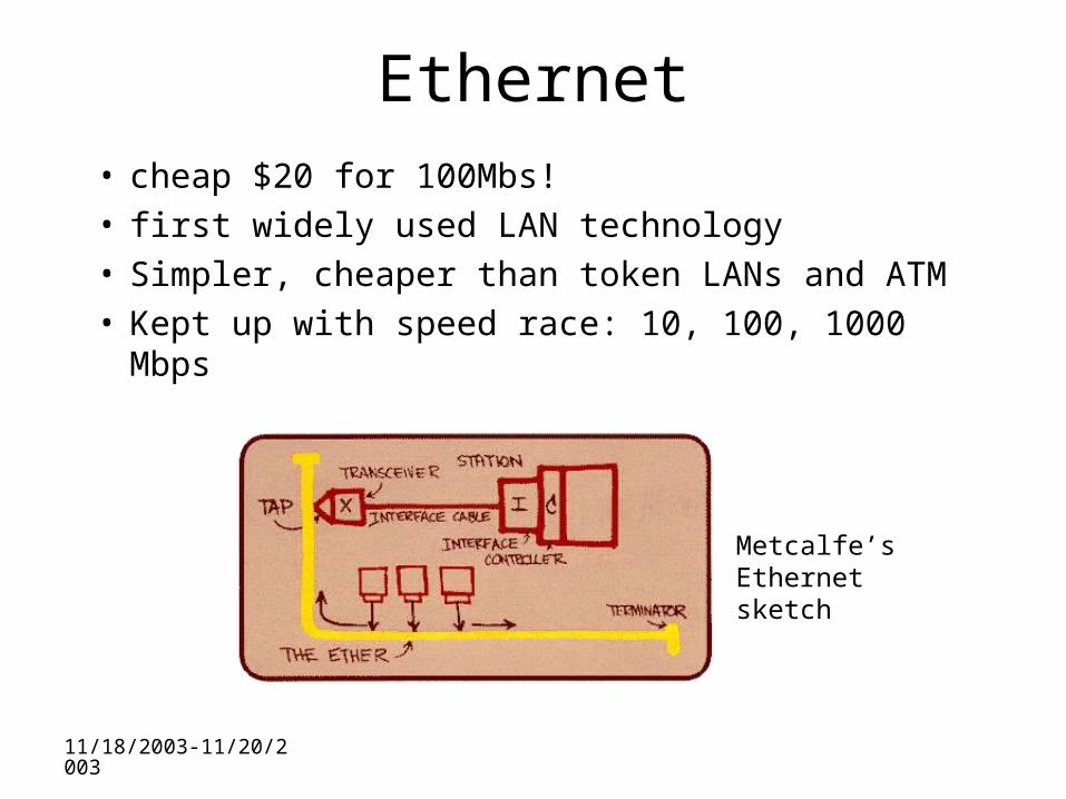
Ethernet• cheap $20 for 100Mbs!• first widely used LAN technology• Simpler, cheaper than token LANs and ATM• Kept up with speed race: 10, 100, 1000 Mbps
Metcalfe’s Ethernetsketch
11/18/2003-11/20/2003
Ethernet Frame Structure
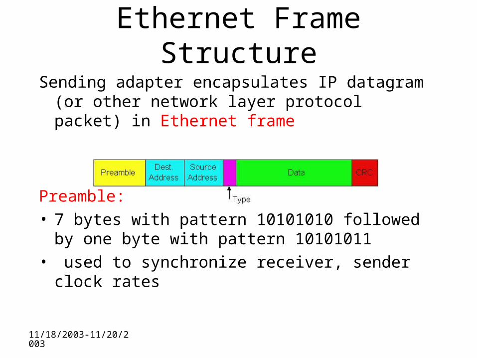
Sending adapter encapsulates IP datagram (or other network layer protocol packet) in Ethernet frame
Preamble: • 7 bytes with pattern 10101010 followed by one
byte with pattern 10101011• used to synchronize receiver, sender clock rates
11/18/2003-11/20/2003
Ethernet Frame Structure (more)
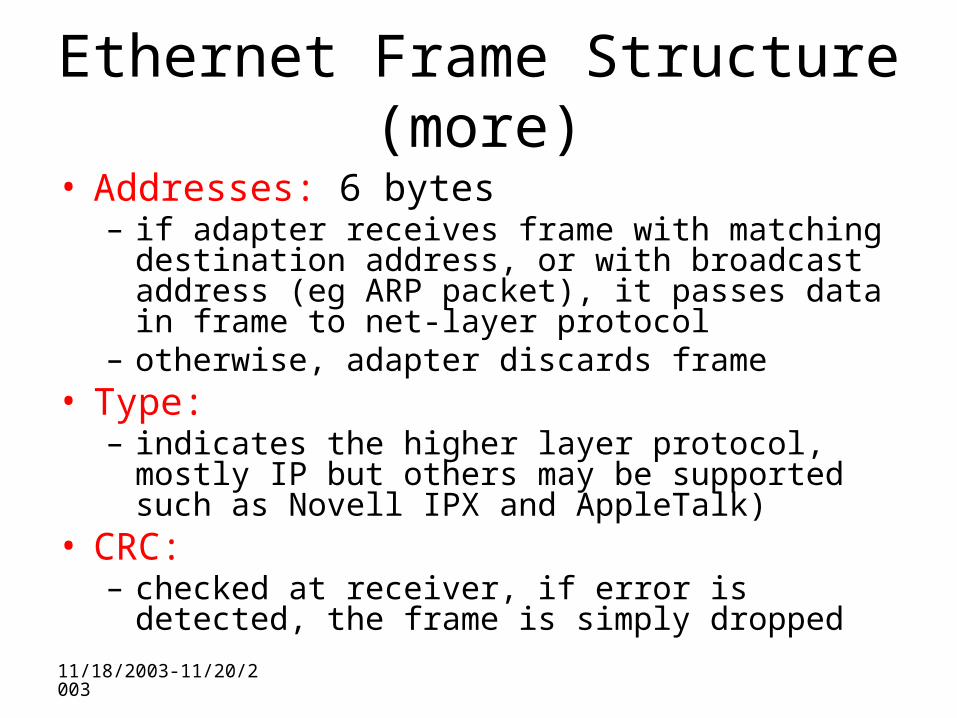
• Addresses: 6 bytes– if adapter receives frame with matching destination
address, or with broadcast address (eg ARP packet), it passes data in frame to net-layer protocol
– otherwise, adapter discards frame• Type:
– indicates the higher layer protocol, mostly IP but others may be supported such as Novell IPX and AppleTalk)
• CRC: – checked at receiver, if error is detected, the frame is
simply dropped
11/18/2003-11/20/2003
Unreliable, connectionless service
• Connectionless: No handshaking between sending and receiving adapter.
• Unreliable: receiving adapter doesn’t send acks or nacks to sending adapter– stream of datagrams passed to network layer can
have gaps– gaps will be filled if app is using TCP– otherwise, app will see the gaps
11/18/2003-11/20/2003
Ethernet CSMA/CD algorithm
1. Adaptor gets datagram from and creates frame
2. If adapter senses channel idle, it starts to transmit frame. If it senses channel busy, waits until channel idle and then transmits
3. If adapter transmits entire frame without detecting another transmission, the adapter is done with frame !
4. If adapter detects another transmission while transmitting, aborts and sends jam signal
5. After aborting, adapter enters exponential backoff: after the mth collision, adapter chooses a K at random from {0,1,2,…,2m-1}. Adapter waits K*512 bit times and returns to Step 2
11/18/2003-11/20/2003
Ethernet’s CSMA/CD (more)
• Jam Signal: make sure all other transmitters are aware of collision; 48 bits;
• Exponential Backoff: – Goal: adapt retransmission attempts to estimated
current load• heavy load: random wait will be longer
– first collision: choose K from {0,1}; delay is K x 512 bit transmission times
– after second collision: choose K from {0,1,2,3}…– after ten collisions, choose K from {0,1,2,3,4,…,1023}
11/18/2003-11/20/2003
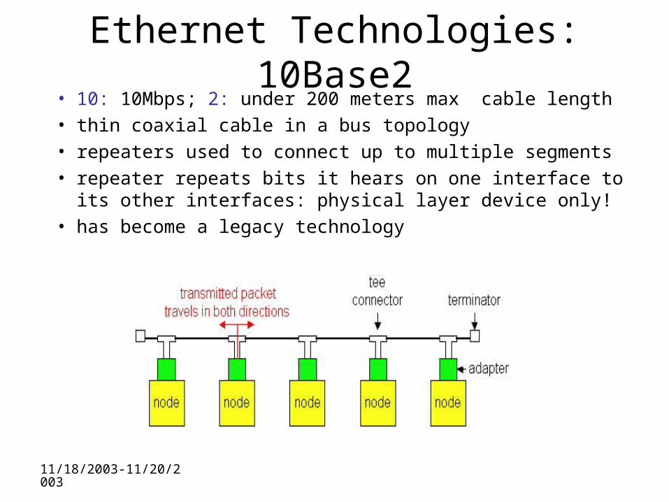
Ethernet Technologies: 10Base2• 10: 10Mbps; 2: under 200 meters max cable length• thin coaxial cable in a bus topology• repeaters used to connect up to multiple segments• repeater repeats bits it hears on one interface to its other
interfaces: physical layer device only!• has become a legacy technology
11/18/2003-11/20/2003
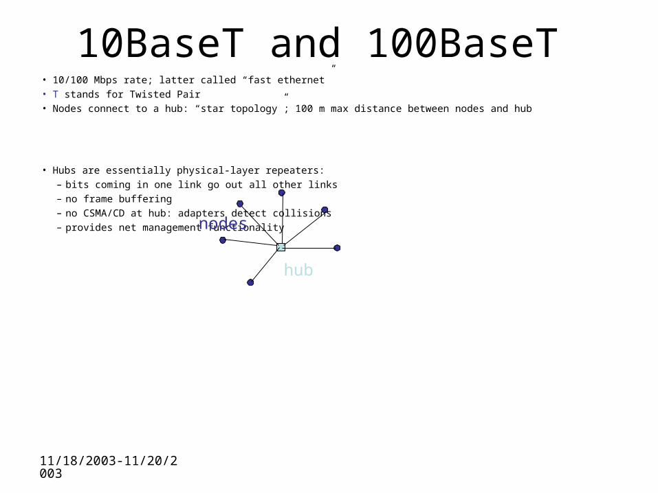
10BaseT and 100BaseT• 10/100 Mbps rate; latter called “fast ethernet”• T stands for Twisted Pair• Nodes connect to a hub: “star topology”; 100 m max distance between nodes and hub
• Hubs are essentially physical-layer repeaters:– bits coming in one link go out all other links– no frame buffering– no CSMA/CD at hub: adapters detect collisions– provides net management functionality
hub
nodes
11/18/2003-11/20/2003
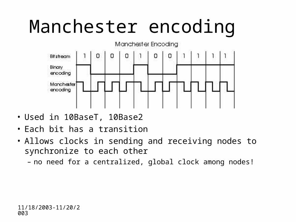
Manchester encoding
• Used in 10BaseT, 10Base2• Each bit has a transition• Allows clocks in sending and receiving nodes to
synchronize to each other– no need for a centralized, global clock among nodes!
11/18/2003-11/20/2003
Gbit Ethernet
• use standard Ethernet frame format• allows for point-to-point links and shared
broadcast channels• in shared mode, CSMA/CD is used; short
distances between nodes to be efficient• uses hubs, called here “Buffered Distributors”• Full-Duplex at 1 Gbps for point-to-point links• 10 Gbps now !
11/18/2003-11/20/2003
Interconnecting LAN segments
• Hubs
• Bridges
• Switches– Remark: switches are essentially multi-port
bridges.– What we say about bridges also holds for
switches!
11/18/2003-11/20/2003
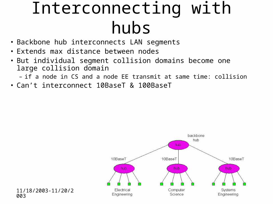
Interconnecting with hubs• Backbone hub interconnects LAN segments• Extends max distance between nodes• But individual segment collision domains become one large collision
domain– if a node in CS and a node EE transmit at same time: collision
• Can’t interconnect 10BaseT & 100BaseT
11/18/2003-11/20/2003
Bridges• Link layer device
– stores and forwards Ethernet frames– examines frame header and selectively forwards
frame based on MAC dest address– when frame is to be forwarded on segment, uses
CSMA/CD to access segment• transparent
– hosts are unaware of presence of bridges• plug-and-play, self-learning
– bridges do not need to be configured
11/18/2003-11/20/2003
Bridges: traffic isolation
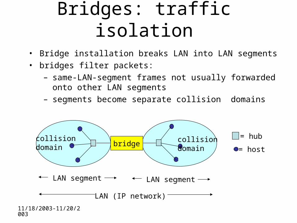
• Bridge installation breaks LAN into LAN segments• bridges filter packets:
– same-LAN-segment frames not usually forwarded onto other LAN segments
– segments become separate collision domains
bridge collision domain
collision domain
= hub
= host
LAN (IP network)
LAN segment LAN segment
11/18/2003-11/20/2003
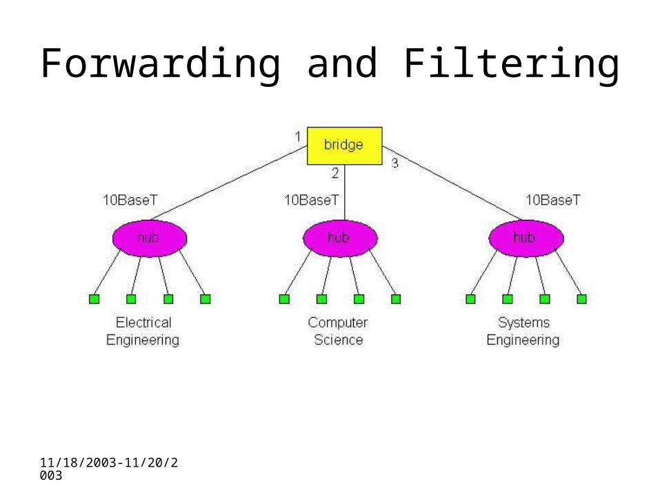
Forwarding and Filtering
11/18/2003-11/20/2003
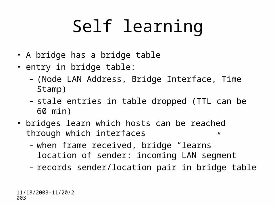
Self learning
• A bridge has a bridge table• entry in bridge table:
– (Node LAN Address, Bridge Interface, Time Stamp)– stale entries in table dropped (TTL can be 60 min)
• bridges learn which hosts can be reached through which interfaces– when frame received, bridge “learns” location of
sender: incoming LAN segment– records sender/location pair in bridge table
11/18/2003-11/20/2003
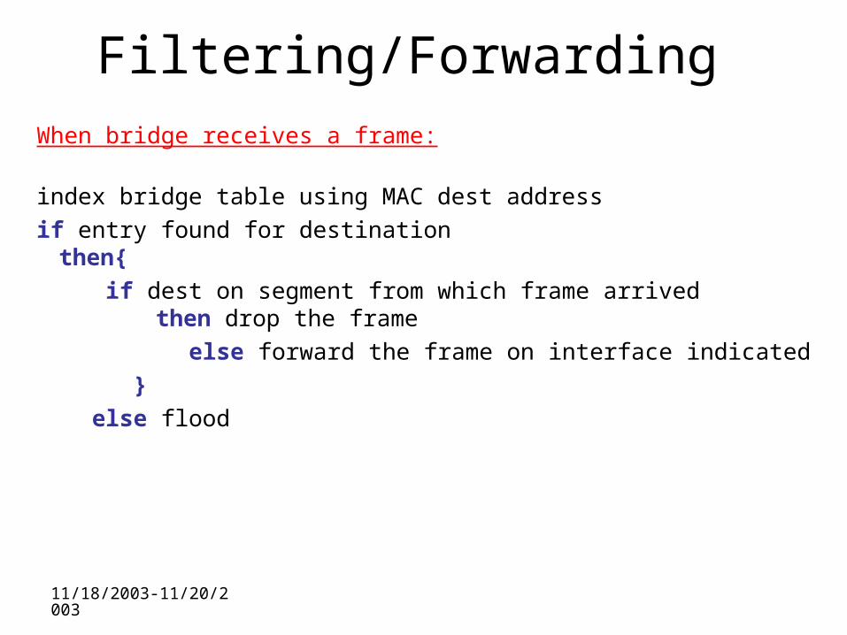
Filtering/ForwardingWhen bridge receives a frame:
index bridge table using MAC dest address
if entry found for destinationthen{
if dest on segment from which frame arrived then drop the frame
else forward the frame on interface indicated
}
else flood
11/18/2003-11/20/2003
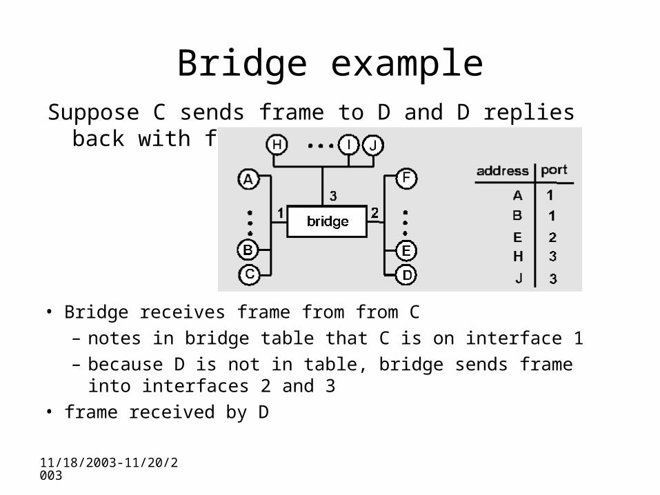
Bridge exampleSuppose C sends frame to D and D replies back with
frame to C.
• Bridge receives frame from from C
– notes in bridge table that C is on interface 1
– because D is not in table, bridge sends frame into interfaces 2 and 3
• frame received by D
11/18/2003-11/20/2003
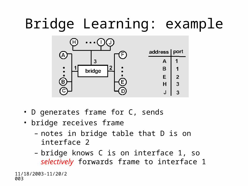
Bridge Learning: example
• D generates frame for C, sends • bridge receives frame
– notes in bridge table that D is on interface 2 – bridge knows C is on interface 1, so selectively
forwards frame to interface 1
11/18/2003-11/20/2003
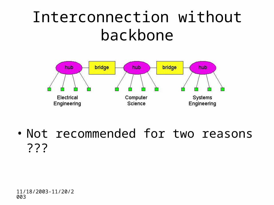
Interconnection without backbone
• Not recommended for two reasons ???
11/18/2003-11/20/2003
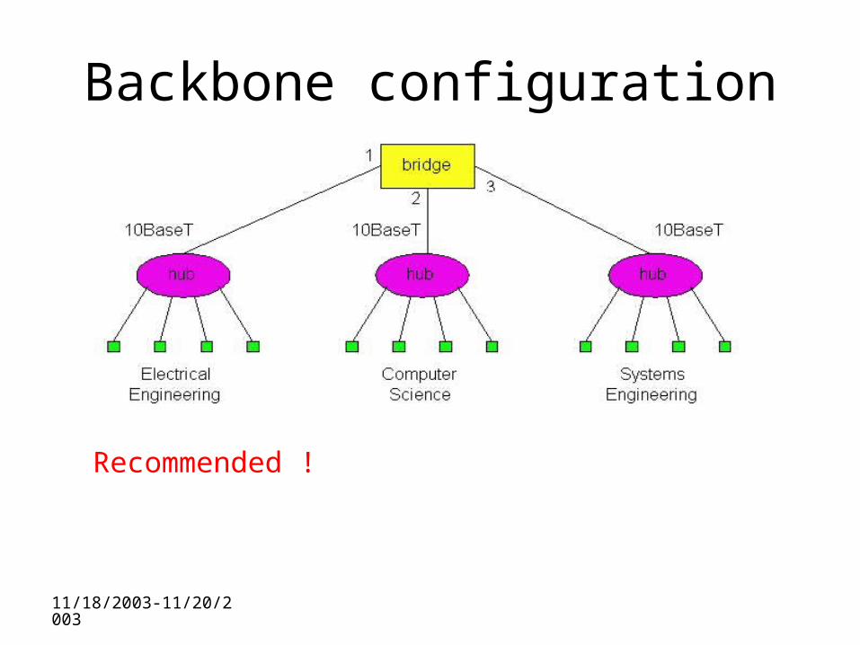
Backbone configuration
Recommended !
11/18/2003-11/20/2003
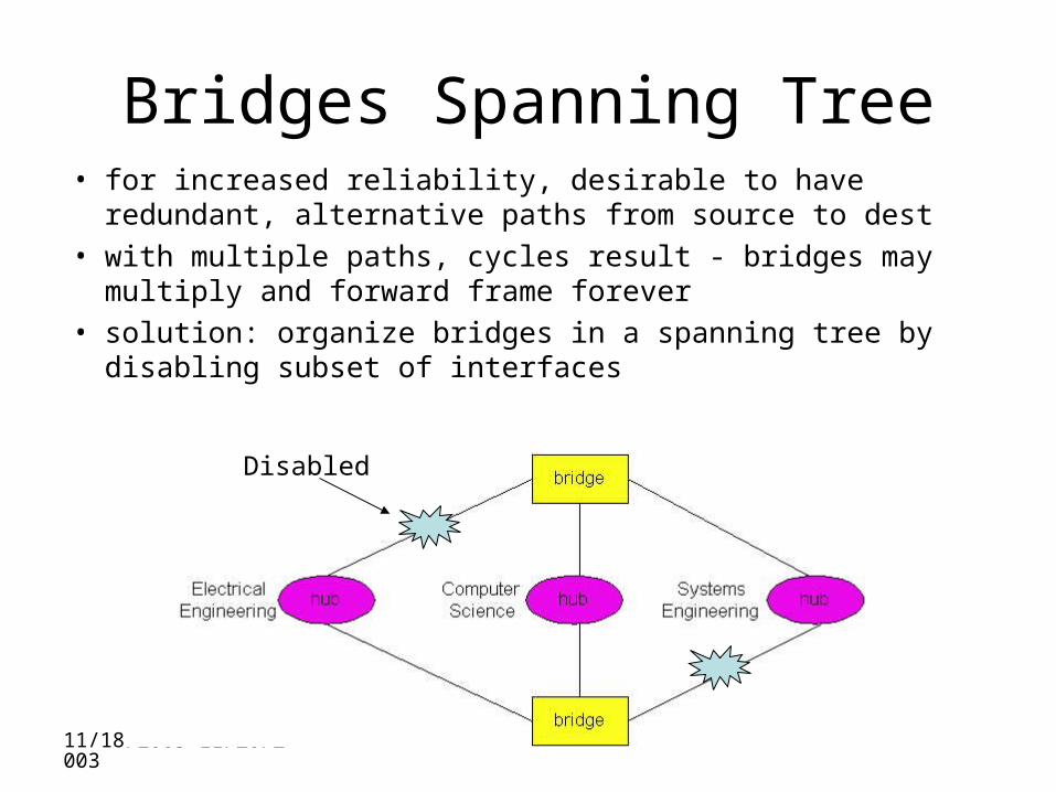
Bridges Spanning Tree• for increased reliability, desirable to have redundant,
alternative paths from source to dest
• with multiple paths, cycles result - bridges may multiply and forward frame forever
• solution: organize bridges in a spanning tree by disabling subset of interfaces
Disabled
11/18/2003-11/20/2003
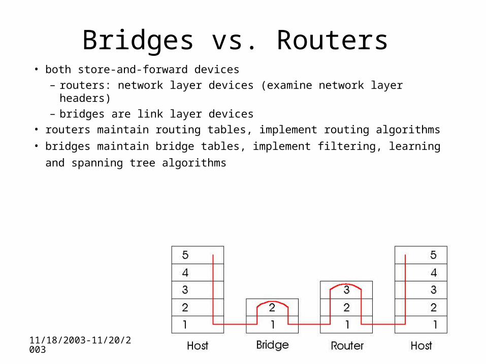
Bridges vs. Routers• both store-and-forward devices
– routers: network layer devices (examine network layer headers)– bridges are link layer devices
• routers maintain routing tables, implement routing algorithms
• bridges maintain bridge tables, implement filtering, learning and
spanning tree algorithms
11/18/2003-11/20/2003
Routers vs. Bridges
Bridges + and -
• + Bridge operation is simpler requiring less packet processing
• + Bridge tables are self learning
• - All traffic confined to spanning tree, even when alternative bandwidth is available
• - Bridges do not offer protection from broadcast storms
11/18/2003-11/20/2003
Routers vs. Bridges
Routers + and -• + arbitrary topologies can be supported, cycling is limited
by TTL counters (and good routing protocols)• + provide protection against broadcast storms• - require IP address configuration (not plug and play)• - require higher packet processing
• bridges do well in small (few hundred hosts) while routers used in large networks (thousands of hosts)
11/18/2003-11/20/2003
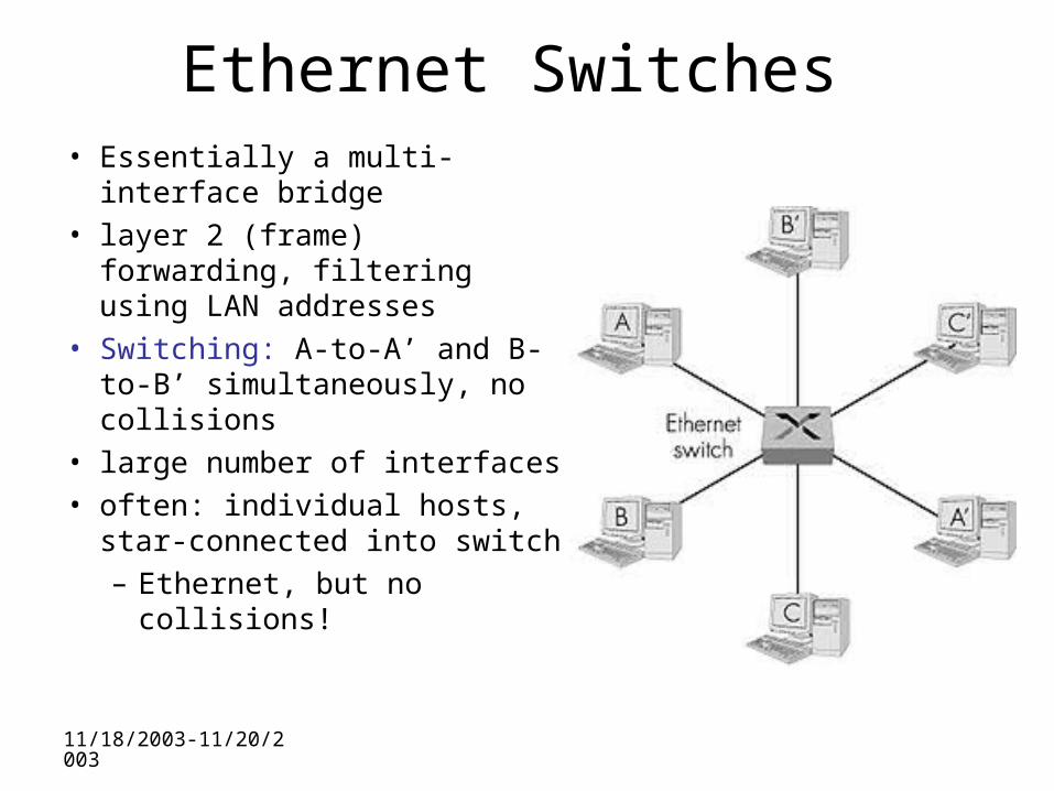
Ethernet Switches• Essentially a multi-interface
bridge• layer 2 (frame) forwarding,
filtering using LAN addresses• Switching: A-to-A’ and B-to-
B’ simultaneously, no collisions
• large number of interfaces• often: individual hosts, star-
connected into switch– Ethernet, but no collisions!
11/18/2003-11/20/2003
Ethernet Switches
• cut-through switching: frame forwarded from input to output port without awaiting for assembly of entire frame
– slight reduction in latency
• combinations of shared/dedicated, 10/100/1000 Mbps interfaces
11/18/2003-11/20/2003
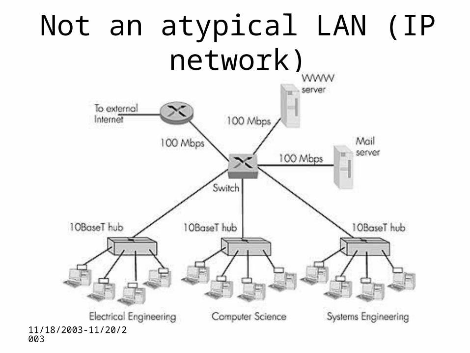
Not an atypical LAN (IP network)
Dedicated
Shared
11/18/2003-11/20/2003
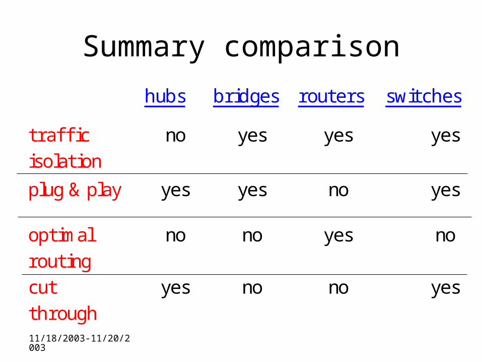
Summary comparison
hubs bridges routers switches
traffi cisolation
no yes yes yes
plug & play yes yes no yes
optimalrouting
no no yes no
cutthrough
yes no no yes
11/18/2003-11/20/2003
Assignments
• Lab 2
11/18/2003-11/20/2003
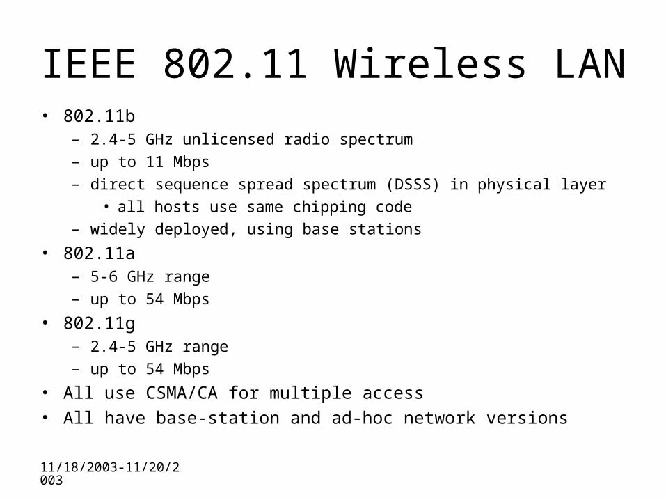
IEEE 802.11 Wireless LAN• 802.11b
– 2.4-5 GHz unlicensed radio spectrum– up to 11 Mbps– direct sequence spread spectrum (DSSS) in physical layer
• all hosts use same chipping code– widely deployed, using base stations
• 802.11a – 5-6 GHz range– up to 54 Mbps
• 802.11g – 2.4-5 GHz range– up to 54 Mbps
• All use CSMA/CA for multiple access• All have base-station and ad-hoc network versions
11/18/2003-11/20/2003
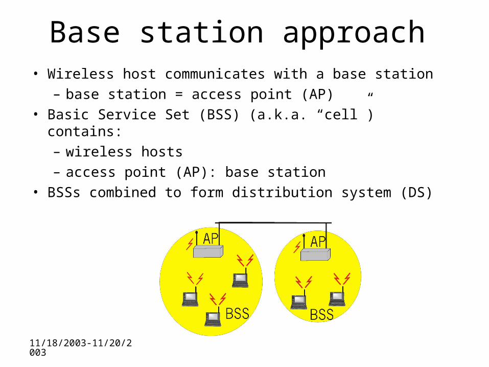
Base station approach• Wireless host communicates with a base station
– base station = access point (AP)• Basic Service Set (BSS) (a.k.a. “cell”) contains:
– wireless hosts– access point (AP): base station
• BSSs combined to form distribution system (DS)
11/18/2003-11/20/2003
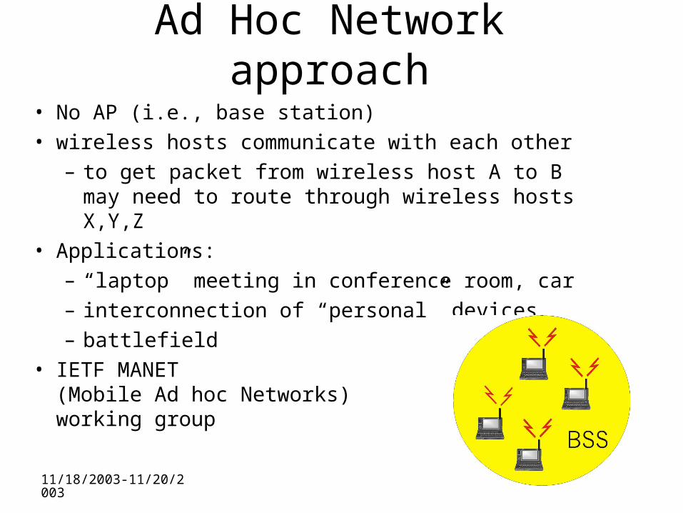
Ad Hoc Network approach
• No AP (i.e., base station)• wireless hosts communicate with each other
– to get packet from wireless host A to B may need to route through wireless hosts X,Y,Z
• Applications:– “laptop” meeting in conference room, car– interconnection of “personal” devices– battlefield
• IETF MANET (Mobile Ad hoc Networks) working group
11/18/2003-11/20/2003
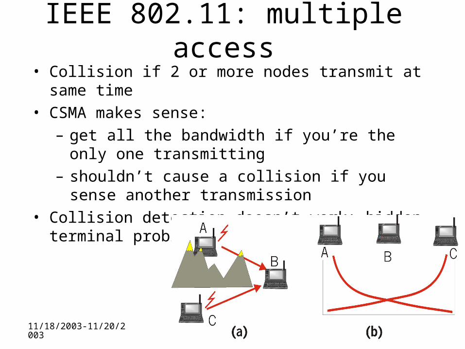
IEEE 802.11: multiple access• Collision if 2 or more nodes transmit at same time• CSMA makes sense:
– get all the bandwidth if you’re the only one transmitting
– shouldn’t cause a collision if you sense another transmission
• Collision detection doesn’t work: hidden terminal problem
11/18/2003-11/20/2003
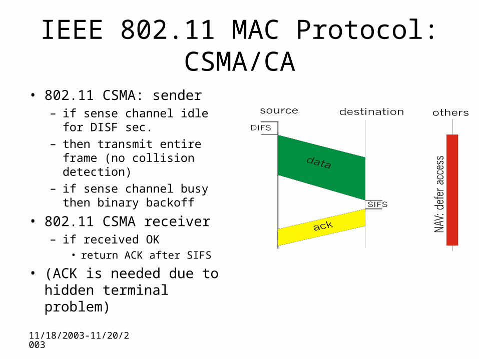
IEEE 802.11 MAC Protocol: CSMA/CA
• 802.11 CSMA: sender– if sense channel idle for
DISF sec.– then transmit entire frame
(no collision detection)– if sense channel busy
then binary backoff
• 802.11 CSMA receiver– if received OK
• return ACK after SIFS
• (ACK is needed due to hidden terminal problem)
11/18/2003-11/20/2003
Collision avoidance mechanisms
• Problem: – two nodes, hidden from each other, transmit
complete frames to base station– wasted bandwidth for long duration !
• Solution: – small reservation packets– nodes track reservation interval with
internal “network allocation vector” (NAV)
11/18/2003-11/20/2003
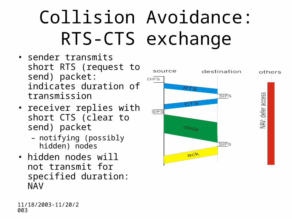
Collision Avoidance: RTS-CTS exchange
• sender transmits short RTS (request to send) packet: indicates duration of transmission
• receiver replies with short CTS (clear to send) packet– notifying (possibly hidden)
nodes
• hidden nodes will not transmit for specified duration: NAV
11/18/2003-11/20/2003
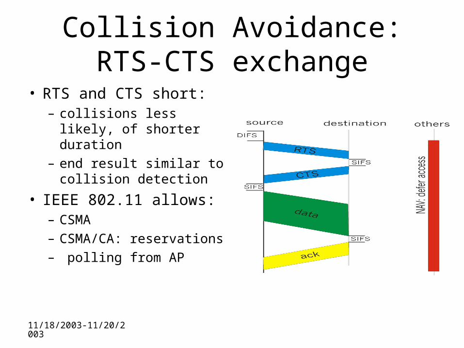
Collision Avoidance: RTS-CTS exchange
• RTS and CTS short:– collisions less likely, of
shorter duration– end result similar to
collision detection
• IEEE 802.11 allows:– CSMA– CSMA/CA:
reservations– polling from AP
11/18/2003-11/20/2003
A word about Bluetooth
• Low-power, small radius, wireless networking technology– 10-100 meters
• omnidirectional– not line-of-sight
infrared• Interconnects gadgets• 2.4-2.5 GHz unlicensed
radio band• up to 721 kbps
• Interference from wireless LANs, digital cordless phones, microwave ovens:– frequency hopping
helps• MAC protocol supports:
– error correction– ARQ
• Each node has a 12-bit address
11/18/2003-11/20/2003
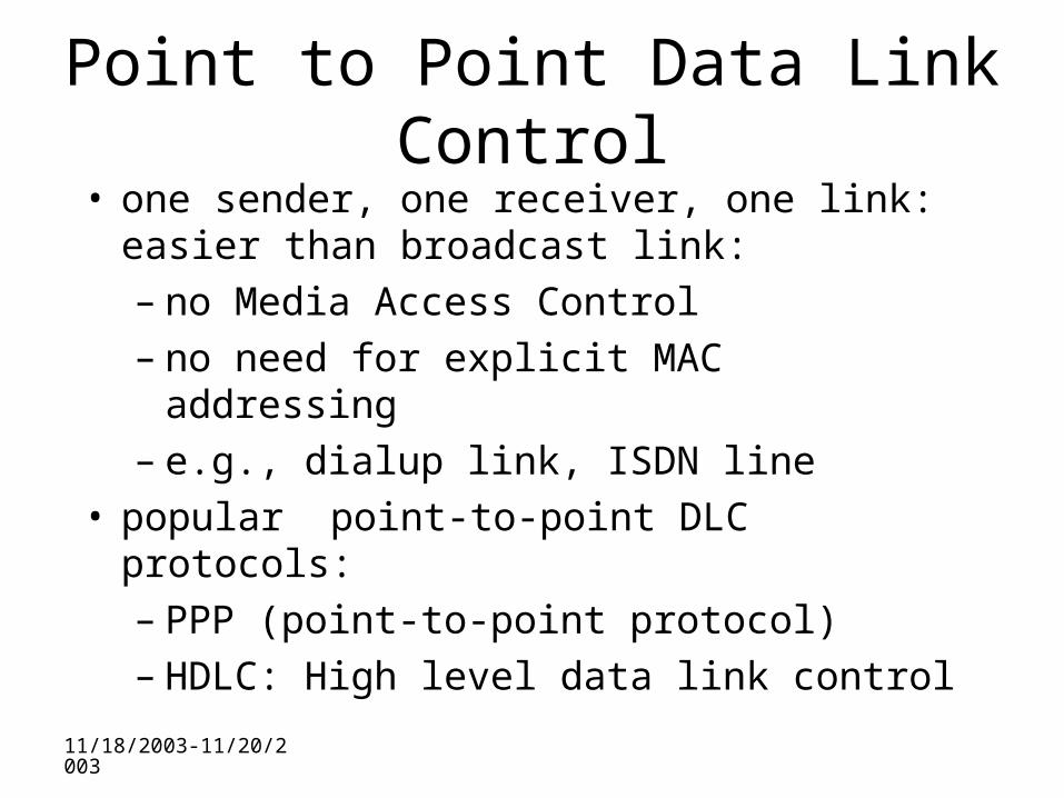
Point to Point Data Link Control• one sender, one receiver, one link: easier
than broadcast link:– no Media Access Control– no need for explicit MAC addressing– e.g., dialup link, ISDN line
• popular point-to-point DLC protocols:– PPP (point-to-point protocol)– HDLC: High level data link control
11/18/2003-11/20/2003
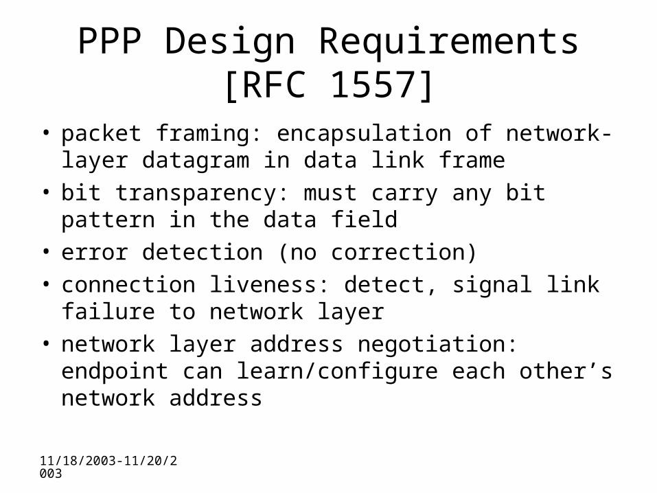
PPP Design Requirements [RFC 1557]
• packet framing: encapsulation of network-layer datagram in data link frame
• bit transparency: must carry any bit pattern in the data field
• error detection (no correction)• connection liveness: detect, signal link failure to
network layer• network layer address negotiation: endpoint can
learn/configure each other’s network address
11/18/2003-11/20/2003
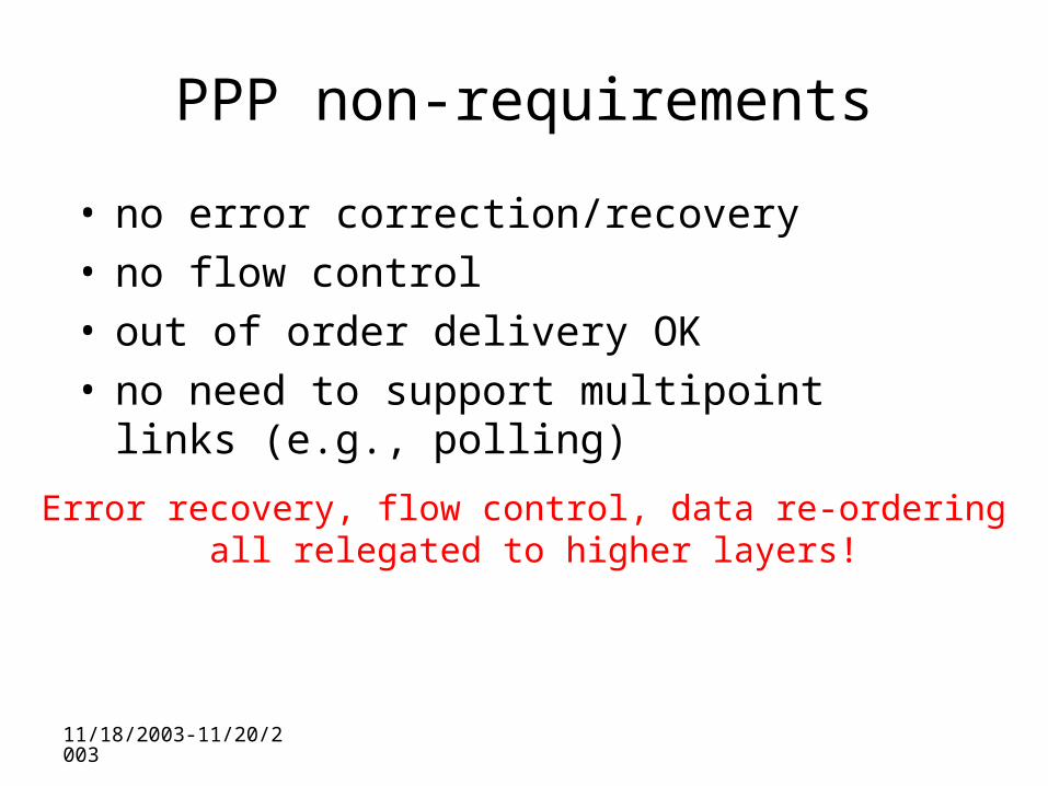
PPP non-requirements
• no error correction/recovery• no flow control• out of order delivery OK • no need to support multipoint links (e.g.,
polling)
Error recovery, flow control, data re-ordering all relegated to higher layers!
11/18/2003-11/20/2003
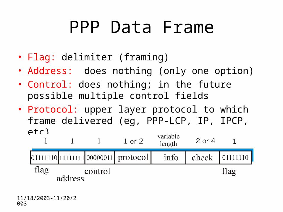
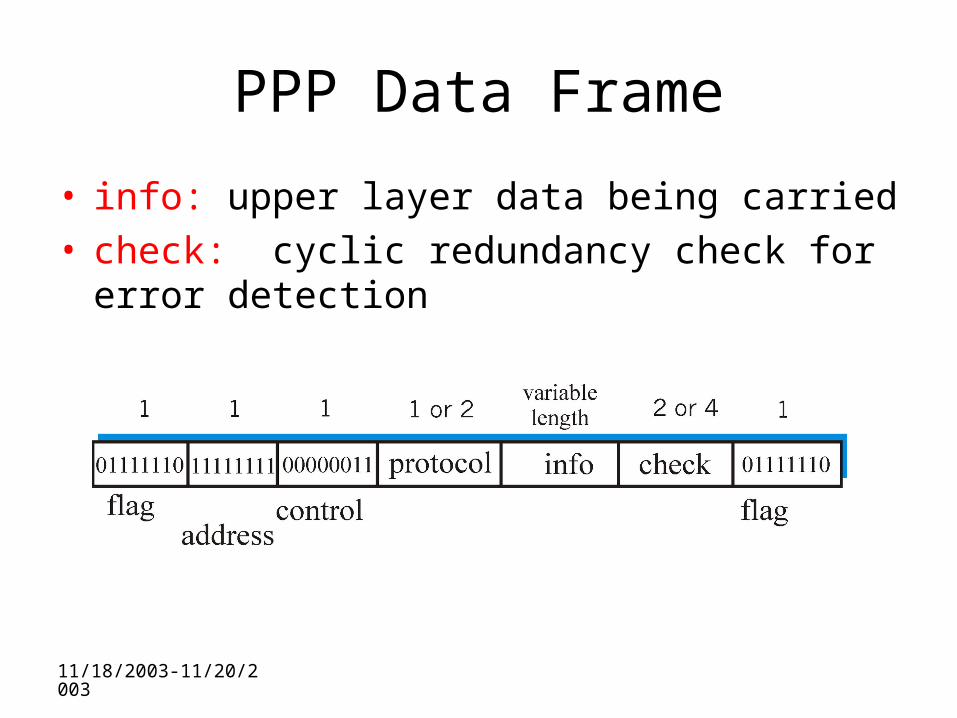
PPP Data Frame
• Flag: delimiter (framing)• Address: does nothing (only one option)• Control: does nothing; in the future possible multiple
control fields• Protocol: upper layer protocol to which frame delivered
(eg, PPP-LCP, IP, IPCP, etc)
11/18/2003-11/20/2003
PPP Data Frame
• info: upper layer data being carried• check: cyclic redundancy check for error
detection
11/18/2003-11/20/2003
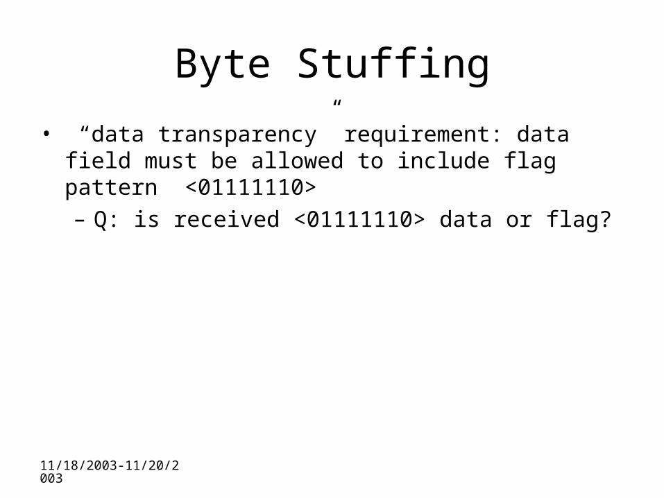
Byte Stuffing
• “data transparency” requirement: data field must be allowed to include flag pattern <01111110>– Q: is received <01111110> data or flag?
11/18/2003-11/20/2003
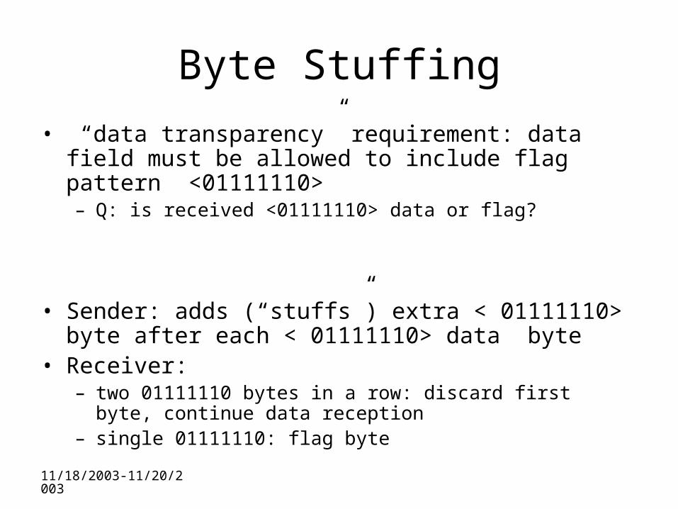
Byte Stuffing
• “data transparency” requirement: data field must be allowed to include flag pattern <01111110>– Q: is received <01111110> data or flag?
• Sender: adds (“stuffs”) extra < 01111110> byte after each < 01111110> data byte
• Receiver: – two 01111110 bytes in a row: discard first byte, continue data
reception– single 01111110: flag byte
11/18/2003-11/20/2003
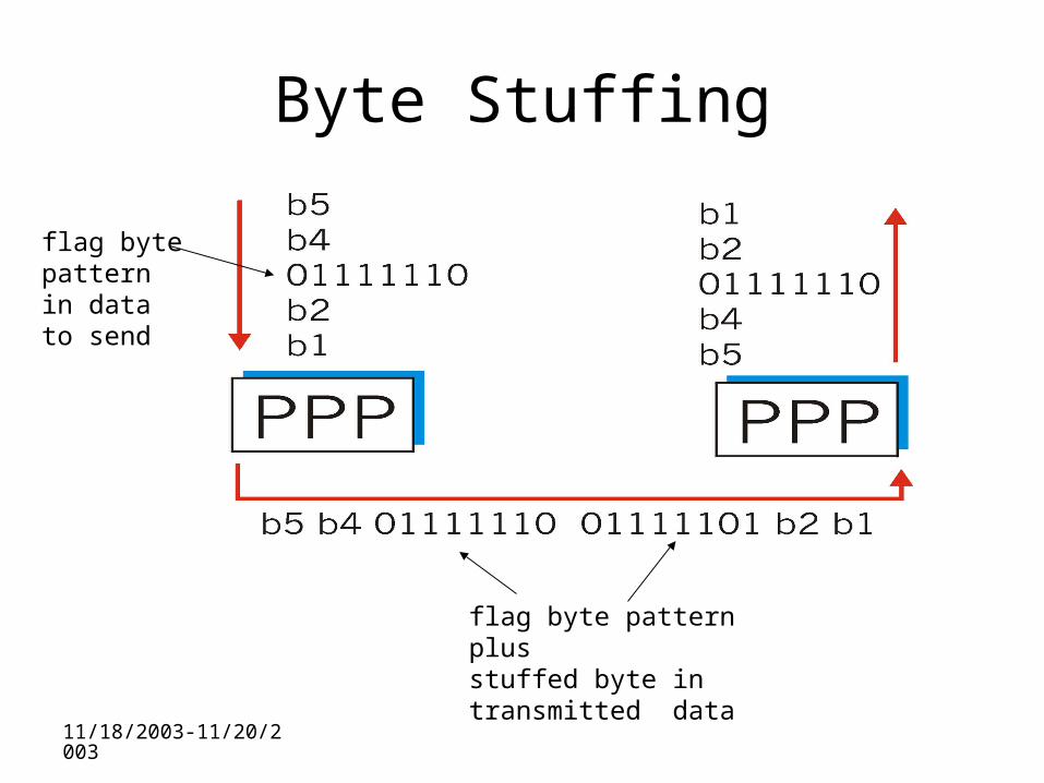
Byte Stuffing
flag bytepatternin datato send
flag byte pattern plusstuffed byte in transmitted data
11/18/2003-11/20/2003
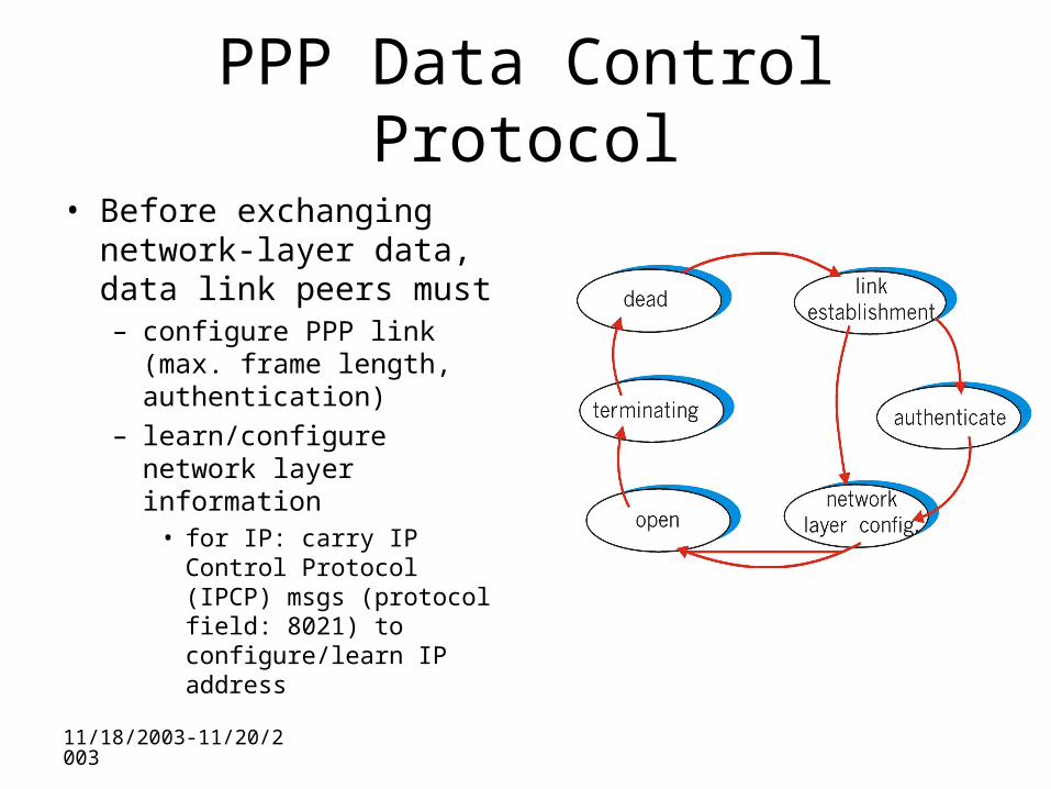
PPP Data Control Protocol
• Before exchanging network-layer data, data link peers must– configure PPP link (max.
frame length, authentication)
– learn/configure network layer information
• for IP: carry IP Control Protocol (IPCP) msgs (protocol field: 8021) to configure/learn IP address
11/18/2003-11/20/2003
Asynchronous Transfer Mode: ATM
• Goal: integrated, end-end transport of carry voice, video, data– meeting timing/QoS requirements of voice,
video (versus Internet best-effort model)– “next generation” telephony: technical roots
in telephone world– packet-switching (fixed length packets,
called “cells”) using virtual circuits
11/18/2003-11/20/2003
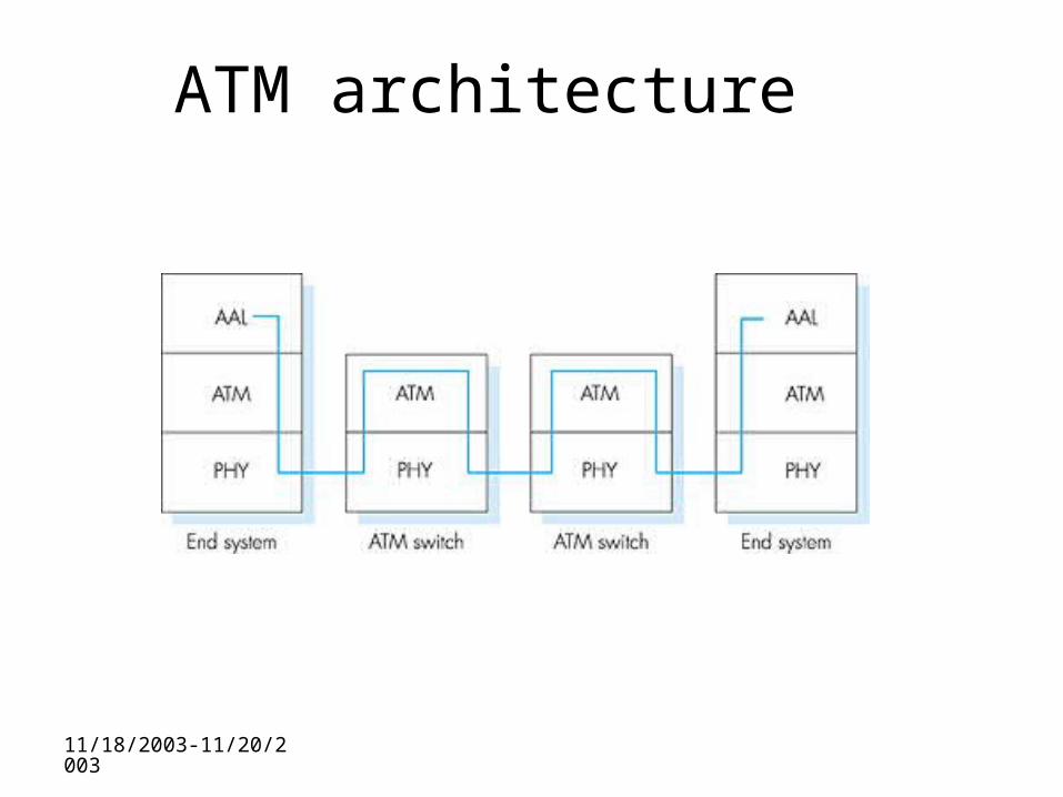
ATM architecture
11/18/2003-11/20/2003
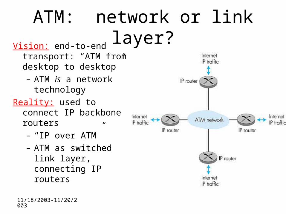
ATM: network or link layer?Vision: end-to-end
transport: “ATM from desktop to desktop”– ATM is a network
technology
Reality: used to connect IP backbone routers – “IP over ATM”– ATM as switched link
layer, connecting IP routers