Embed Size (px)
Citation preview

1111111111111111111inuuu1111111111u~(12) United States Patent
deMayo
(54) METHOD AND DEVICE FOR EXTRACTIONOF LIQUIDS FROM A SOLID PARTICLEMATERIAL
(71) Applicant: Benjamin deMayo, Carrollton, GA(US)
(72) Inventor: Benjamin deMayo, Carrollton, GA(US)
(*) Notice: Subject to any disclaimer, the term of thispatent is extended or adjusted under 35U.S.C. 154(b) by 626 days.
(21) Appl. No.: 14/299,986
(22) Filed: Jun. 9, 2014
(65) Prior Publication Data
US 2014/0360923 Al Dec. 11, 2014
Related U.S. Application Data
(63) Continuation-in-part of application No. 12/855,267,filed on Aug. 12, 2010, now abandoned.
(60) Provisional application No. 61/233,241, filed on Aug.12, 2009.
(51) Int. Cl.CLOG 31/10 (2006.01)CLOG 1/00 (2006.01)B04B 3/00 (2006.01)BOLD 21/00 (2006.01)BOLD 21/26 (2006.01)B03B 9/02 (2006.01)B04B 3/02 (2006.01)B04B 3/04 (2006.01)B04B 5/04 (2006.01)B04B 15/02 (2006.01)BOIL 3100 (2006.01)
1050
1026
1028 1055 1012
(io) Patent No.: US 9,688,922 B2(45) Date of Patent: Jun. 27, 2017
(52) U.S. Cl.CPC ........... CIOG 31/10 (2013.01); BOLD 21/009
(2013.01); BOLD 21/262 (2013.01); B03B 9/02(2013.01); B04B 3/00 (2013.01); B04B 3/025
(2013.01); B04B 3/04 (2013.01); B04B 5/0414(2013.01); B04B 5/0421 (2013.01); B04B
15/02 (2013.01); CLOG 1/00 (2013.01); BOLD2221104 (2013.01); BOIL 315021 (2013.01);
B04B 200510435 (2013.01)
(58) Field of Classification SearchCPC . C10G 1/00; C10G 1/04; C10G 1/045; C10G
1/047; B04B 3/00See application file for complete search history.
(56) References Cited
U.S. PATENT DOCUMENTS
1,718,141 A 6/1929 Hall2,320,106 A 5/1943 South2,840,240 A 6/1958 Snyder2,871,180 A 1/1959 Lowman, Jr. et al.
(Continued)
OTHER PUBLICATIONS
Budziak, Study of fines in bitumen extracted from oil sands by heatcentrifugation, 1988 Fuel vol. 67 December pages 633-1638.
Primary Examiner Renee Robinson
(57) ABSTRACT
A method, system, and device for separating oil from oilsands or oil shale is disclosed. The method includes heatingthe oil sands, spinning the heated oil sands, confining thesand particles mechanically, and recovering the oil substan-tially free of the sand. The method can be used without theaddition of chemical extraction agents. The system includesa source of centrifugal force, a heat source, a separationdevice, and a recovery device. The separation deviceincludes a method of confining the sands while allowing theoil to escape, such as through an aperture.
1011
1014
7 Claims, 42 Drawing Sheets
1036
1026
1034
https://ntrs.nasa.gov/search.jsp?R=20170006157 2018-07-05T19:13:43+00:00Z

US 9,688,922 B2Page 2
(56) References Cited 5,340,467 A 8/1994 Gregoli5,520,605 A * 5/1996 Leung ..................
U.S.PATENT DOCUMENTS5,626,743 A 5/1997 Humphreys
3,161,581 A 12/1964 Tiedje et al. 5,762,780 A 6/1998 Rendall et al.3,466,240 A 9/1969 Steinmetz 5,770,049 A 6/1998 Humphreys3,530,041 A 9/1970 Erskine et al. 5,795,444 A 8/1998 Rendall et al.3,891,550 A 6/1975 Gray et al. 5,876,592 A 3/1999 Tipman et al.3,893,907 A 7/1975 Canevari 5,985,138 A 11/1999 Humphreys3,951,749 A 4/1976 Fairbanks, Jr. et al. 6,004,455 A 12/1999 Rendall3,953,317 A 4/1976 Myers et al. 6,119,870 A 9/2000 Maciejewski et al.4,029,568 A 6/1977 Pittman et al. 6,214,213 B1 4/2001 Tipman et al.4,110,194 A 8/1978 Peterson et al. 6,251,290 B1 6/2001 Conaway4,110,195 A 8/1978 Harding 6,576,145 B2 6/2003 Conaway et al.4,224,138 A 9/1980 Kruyer 7,192,092 B2 3/2007 Watson4,240,897 A 12/1980 Clarke
2001/0030145 Al 10/2001 Conaway4,250,016 A 2/1981 Estes et al.
2002/0003115 Al 1/2002 Conaway et al.4,338,185 A 7/1982 Noelle4,347,971 A 9/1982 Novoselac 2004/0035755 Al 2/2004 Reeves
4,459,200 A 7/1984 Dente et al. 2004/0129646 Al 7/2004 Conaway et al.
4,498,971 A 2/1985 Angelov et al. 2006/0016760 Al 1/2006 Bozack et al.
4,515,685 A 5/1985 Yeh 2006/0138055 Al 6/2006 Garner et al.
4,533,459 A 8/1985 Dente et al. 2007/0131590 Al 6/2007 Bozack et al.4,704,200 A 11/1987 Keane 2007/0181465 Al 8/2007 Collette4,906,355 A 3/1990 Lechnick et al. 2007/0205141 Al 9/2007 Freeman et al.4,966,685 A 10/1990 Hall et al. 2008/0000810 Al 1/2008 Garner et al.5,122,259 A 6/1992 Nielson 2008/0035531 Al 2/2008 Coveley5,223,148 A 6/1993 Tipman5,320,746 A 6/1994 Green et al. * cited by examiner
B04B 1/20494/50

U.S. Patent Jun. 27, 2017 Sheet 1 of 42 US 9,688,922 B2
a
104
FIG. 1
U.S. Patent Jun. 27, 2017 Sheet 2 of 42 US 9,688,922 B2
102
FIG. 2
'1t
W,

U.S. Patent Jun. 27, 2017 Sheet 3 of 42 US 9,688,922 B2
PM
100
WE
FIG. 3
'I'
)2
:isles

U.R. Patent J#n 27 2017 Sheet of 42 US 9,688,922 G2
~
%:1-}
2% fm,,~-- to &)~o ( 2
§ Gds A
Afm t
S } ! A / :6 $ 15 4 §
Spin atM.
)d # Speed, 3300 fpm moutes
FIG. 4

U.R. Patent J#n 27 2017 Sheet of 42 US 9,688,922 G2
4:
72C
3 10 12 }4 )fn Time, minutes

U.S. Patent Jun. 27, 2017 Sheet 6 of 42 US 9,688,922 B2
Spin ; .. minutes.

U.S. Patent Jun. 27, 2017 Sheet 7 of 42 US 9,688,922 B2
It i
Fig. 7

U.S. Patent Jun. 27, 2017 Sheet 8 of 42 US 9,688,922 B2
306
EM
FIG. 8
U.S. Patent Jun. 27, 2017 Sheet 9 of 42 US 9,688,922 B2
302
MUM

U.S. Patent Jun. 27, 2017 Sheet 10 of 42 US 9,688,922 B2
302
LZ-602
U.S. Patent Jun. 27, 2017 Sheet 11 of 42 US 9,688,922 B2
r4lem
FIG. 11
Znl
I' 1
E
rm

U.S. Patent ,Tun. 27, 2017 Sheet 12 of 42 US 9,688,922 B2
302
17
FIG. 12
04 802

U.S. Patent Jun. 27, 2017 Sheet 13 of 42 US 9,688,922 B2
KIM
"m
m

U.S. Patent Jun. 27, 2017 Sheet 14 of 42 US 9,688,922 B2
10361011
1024 1014 7041050
1020r 101.6
1.030 1032 10261026 y 1018
702 602
1034
1022
[ i'1028 1055 1012
FIG. 14
FIG. 14a

U.S. Patent Jun. 27, 2017 Sheet 15 of 42 US 9,688,922 B2
ITI
1011 1016
1010
FIG. 15
I~
C

U.S. Patent Jun. 27, 2017 Sheet 16 of 42 US 9,688,922 B2
UWE
[HE•
U.S. Patent
1202
[KIM
Jun. 27, 2017 Sheet 17 of 42
FIG. 17
INK
US 9,688,922 B2
1204

U.S. Patent Jun. 27, 2017 Sheet 18 of 42 US 9,688,922 B2
In
FIG. 18

U.S. Patent Jun. 27, 2017 Sheet 19 of 42 US 9,688,922 B2
L'
14(
i

U.S. Patent Jun. 27, 2017 Sheet 20 of 42 US 9,688,922 B2
602
a 7021 02
1504
0
I' r
rl,
E6
M
n*
1504602
e ~T1
FIG. 20

U.S. Patent Jun. 27, 2017
r 't
Sheet 21 of 42 US 9,688,922 B2
1.600
FIG. 21
606
1608
612
1610
U.S. Patent
702
,Tun. 27, 2017 Sheet 22 of 42 US 9,688,922 B2
FIG. 22
mm
it
M
IEI

U.S. Patent ,Tun. 27, 2017 Sheet 23 of 42 US 9,688,922 B2
a
IQ
IQ
602
704
U
102
FIG. 23
602
I7
Cl

U.S. Patent
2114
F~1
,Tun. 27, 2017 Sheet 24 of 42 US 9,688,922 B2
'%I AAA

U.S. Patent Jun. 27, 2017 Sheet 25 of 42
21.04
2114
"[IN
2202
2106
US 9,688,922 B2

U.S. Patent Jun. 27, 2017 Sheet 26 of 42 US 9,688,922 B2
WE
2116
mm

U.S. Patent Jun. 27, 2017 Sheet 27 of 42 US 9,688,922 B2
2L
HWOMWA

U.S. Patent
2402
Jun. 27, 2017 Sheet 28 of 42 US 9,688,922 B2
BE
mm
'.502
2408
U.S. Patent Jun. 27, 2017 Sheet 29 of 42 US 9,688,922 B2
i
WON

U.S. Patent Jun. 27, 2017 Sheet 30 of 42 US 9,688,922 B2
240L
FIG. 30
GJVV
;402
110
1

U.S. Patent Jun. 27, 2017 Sheet 31 of 42 US 9,688,922 B2
M
2506
FIG. 31
2402
WWI,

U.S. Patent Jun. 27, 2017 Sheet 32 of 42 US 9,688,922 B2
t
Env
m
FIG. 32

U.S. Patent Jun. 27, 2017 Sheet 33 of 42 US 9,688,922 B2
3006
E
3008
FIG. 33
3004

U.S. Patent Jun. 27, 2017
3002
Sheet 34 of 42 US 9,688,922 B2
3008
FIG. 34
1

U.S. Patent Jun. 27, 2017 Sheet 35 of 42 US 9,688,922 B2
3002
3006 30
30043004
a b 3008
FIG. 35
3010

U.S. Patent Jun. 27, 2017 Sheet 36 of 42 US 9,688,922 B2
J' A " 30043002
3302
a
3006
kA
3008 3304
b C d
FIG. 36
3010

U.S. Patent Jun. 27, 2017 Sheet 37 of 42 US 9,688,922 B2
36
341
3406 3402
FIG. 37

U.S. Patent
I
MIT
Jun. 27, 2017 Sheet 38 of 42 US 9,688,922 B2
m
M

U.S. Patent Jun. 27, 2017 Sheet 39 of 42
k ,, l U
3612
lac
US 9,688,922 B2
3610

U.S. Patent Jun. 27, 2017 Sheet 40 of 42 US 9,688,922 B2
,1,
Im
G. 40a
3704

U.S. Patent Jun. 27, 2017 Sheet 41 of 42 US 9,688,922 B2
3814 3802 3806
3830~~ III III II II
3804
3812 'W- 3818~rsn
FIG. 41a
FIG. 41

U.S. Patent
mm
Jun. 27, 2017
mm
FIG. 42
Sheet 42 of 42
M
US 9,688,922 B2
um

US 9,688,922 B2
METHOD AND DEVICE FOR EXTRACTIONOF LIQUIDS FROM A SOLID PARTICLE
MATERIAL
RELATED APPLICATIONS
The present patent document is a division of patentapplication Ser. No. 12/855,267 filed Aug. 12, 2010, whichclaims the benefit of the filing date under 35 U.S.C. §119(e)of Provisional U.S. Patent Application Ser. No. 61/233,241,filed Aug. 12, 2009, each of which are hereby incorporatedby reference in their entirety.
FEDERALLY SPONSORED RESEARCH ORDEVELOPMENT
This invention was made with Government support undercontract NNG05G765H, awarded by NASA. The Govern-ment has certain rights in this invention.
BACKGROUND
Given high oil prices and the finite amount of crude oilavailable, unconventional petroleum reserves in the form of,for example, oil sands and oil shale are becoming moreattractive as an alternative source of hydrocarbons. Oil sandsare found in over 60 countries in the world, including theUnited States. The main deposits occur in Alberta, Canada,and represent the second largest reserves of petroleum in theworld, after those in Saudi Arabia.
BRIEF SUMMARY
This invention relates to a process for extracting liquids,such as bitumen or crude oil, from discrete solid particles,such as sand or shale. The invention is particularly appli-cable to oil sands and oil shale in which oil is present as ahighly viscous liquid.
BRIEF DESCRIPTION OF THE DRAWINGS
2FIG. 14 is a cross-sectional view of a third system.FIG. 15 is a perspective view of the third system.FIG. 16 is a perspective view of the fourth system.FIG. 17 is a perspective view of the fourth system with a
5 top and a bottom.FIG. 18 is a top view of the fourth system.FIG. 19 is an exploded detail of the fourth system.FIG. 20 is an exemplary top view of the spinning and
cleaning process of the fourth system.10 FIG. 21 is a perspective view of a fifth system.
FIG. 22 is a cross section view of the fifth system.FIG. 23 is a cross-sectional view of an exemplary sepa-
ration process in the fifth system.FIG. 24 is a cross-sectional view of a sixth system.
15 FIG. 25 is a cross-sectional view of the sixth systemsurrounded by a liquid collector.FIG. 26 is a cross-sectional view of the sixth system in an
open conformation.FIG. 27 is a perspective view of the seventh system.
20 FIG. 28 is a cross-sectional view of the seventh system ina closed conformation.FIG. 29 is a perspective view of a component of the
seventh system.FIG. 30 is a cross-sectional view of the seventh system.
25 FIG. 31 is a second cross-sectional view of the seventhsystem.FIG. 32 is a partial cross-sectional view of the eighth
system.FIG. 33 is a first cross-sectional view of the ninth system.
30 FIG. 34 is a second cross-sectional perspective view ofthe ninth system.
FIG. 35 is a third cross-sectional view of the ninth system.FIG. 36 is a fourth cross-sectional view of the ninth
35
40
The physical process for extracting liquid such as oil fromthe solid-liquid mixture such as oil sands or oil shaleinvolves submitting the heated mixture to centrifugal forcesto allow the liquid to mechanically separate from the solid 45particles and exit the device through small apertures.
FIG. 1 is a cross-sectional view of a first system.FIG. 2 is a cross-sectional view of the first system
unassembled.FIG. 3 is an exploded detail of the first system. 50
FIG. 4 is a diagram illustrating the effect of spinning time.FIG. 5 is a diagram illustrating the effect of temperature.FIG. 6 is a diagram illustrating the effect of the spin rate.FIG. 7 is a cross-sectional view of a second system.FIG. 8 is a top view of the bottom portion of the second 55
system.FIG. 9 is a perspective view of the top and bottom
portions of the second system.FIG. 10 is a cross-sectional view of the second system in
an open conformation. 60
FIG. 11 is a cross-sectional view of the second system ina closed conformation and surrounded by a liquid collector.
FIG. 12 is a cross-sectional view of the second system inan open conformation and surrounded by a cylindricalparticle collector. 65
FIG. 13 is a cross-sectional view of the second system inopen conformation with a solids-liquids mixture inside.
system.FIG. 37 is a perspective and cross-sectional view of the
tenth system.FIG. 38 is a cross-sectional view of the tenth system.FIG. 39 is a perspective view of the eleventh system.FIG. 40 is a first cross-sectional view of the eleventh
system.FIG. 41 is a second cross-sectional view of the twelfth
system.FIG. 42 is a cross-sectional view of the thirteenth system.
DETAILED DESCRIPTION
Oil sands (also referred to as tar sands) are found in oversixty countries in the world, including the United States. Oilsands consist mainly of bitumen, water, mineral particles,sand, and clay. Bitumen is a natural, tar-like mixture ofhydrocarbons that exists as a solid at room temperature. Innature, bitumen has a density range of 8° to 12° API, and atroom temperature its viscosity is greater than 50,000 centi-poises.The physical process disclosed for separating liquids from
solids uses fewer natural resources to produce bitumen fromoil sand than the conventional method of separation. Theconventional method of separating bitumen from oil sandrequires more than 1,000 cubic feet of natural gas to separateone barrel of bitumen from two tons of oil sand, accordingto the National Energy Board of Canada. However, thephysical process disclosed for separating liquids from solidsrequires less than 190 cubic feet of natural gas and no freshwater or other solvents to produce one barrel of bitumen.The physical process disclosed produces a clean effluent.
The only ingredient in the produced effluent is sand, whichalmost all of the oil is removed. On a laboratory scale,

US 9,688,922 B23
approximately over 85% of the available oil is removed. Thephysical process disclosed is also effective on a laboratoryscale. Approximately 90% of the available oil is removed inless than 15 minutes.The physical process disclosed is a simple mechanical 5
method. Using less than 25% of the energy required of theconventional hot-water process method to separate oil fromoil sands, the disclosed physical process is environmentallyconscious.As an illustration, the energy needed to heat oil sand is io
calculated by multiplying the oil sand specific heat atconstant pressure by the mass of the oil sand and the changein temperature. For example, the energy needed to heat twotons (2,000 kg) of oil sand with a specific heat at constantpressure of 1 kJ/kg-K from 0° C. up to 100° C. equals 15200,000 kJ. The specific heat at constant pressure of Utah oilsand ranges from 0.67 kJ/kg-K to 1.57 kJ/kg-K in thetemperature range of 100-350° C. Converted to the energyunits of BTU based on 1.055 kJ per BTU, 200,000 kJ equals189,574 BTU. Each cubic foot of natural gas contains 1,028 20BTU of energy, as a result, 189,574 BTU equals 184 cubicfeet of natural gas. Therefore, the physical process disclosedfor separating liquids from solids may require less than 190cubic feet of natural gas to separate one barrel of bitumenfrom two tons of oil sand, which is 80% less than the 1,000 25cubic feet used in the conventional separation method.
Additionally, the negative impact on the environmentfrom the physical process disclosed for separating liquidsfrom solids may be less than the conventional separationmethod because the physical process disclosed does not 30require any water to separate bitumen from oil sand. Con-versely, the conventional separation process requires up to 4barrels of fresh water to produce one barrel of bitumen fromtwo tons of oil sand. The spent water used in the conven-tional oil separation process is suspected to cause environ- 35mental, wildlife, and health problems. The spent water maycontain chemicals used in the conventional separation pro-cess and may enter rivers and fresh ground water suppliesafter leaking from spent water retention ponds. Therefore,the physical process disclosed for separating liquids from 40solids may be less harmful to the environment than theconventional separation method.A physical process for separating liquids from solids is
disclosed. As a non-limiting example, this physical processmay be used to separate liquids, such as oil, from solid 45particles, such as sand or shale. The process may involve atleast the following steps in any order (a) applying heat to amixture of solids and liquids; (b) rapidly spinning themixture; and (c) confining the solid particles mechanically.A first system includes a separation device 90 as shown in 50
FIG. 1. The separation device 90 may be made up of one ormore tubes such as test tubes. The separation device 90 may,for example, include a first tube 106 and a second tube 100.The tubes 106, 100 of this example are dimensioned suchthat the second tube 100 fits inside of the first tube 106, for 55example, in a nested conformation. The second tube 100 hasan aperture 102 at one end. In this example, the aperture mayhave a diameter of approximately 0.40-1.50 mm, 0.45-1.35mm, 0.80-1.30 mm, or 0.90-1.20 mm. The aperture may befunnel shaped as shown in FIG. 3, and may have a diameter 60that decreases from its originating point to its terminatingpoint. However, the optimal aperture size may vary withother variables, such as the type of solid or liquid beingseparated or other considerations.The separation device 90 may be dimensioned as 65
described below and illustrated by FIG. 2. The dimensionsare representative of this system but may be varied depend-
4ing upon, for example the system, production needs, andtype of solids and liquids being separated.The first tube 106 of this example may be, for example but
not limited to, a 15 ml centrifuge tube. The second tube 100of this example may be, for example but not limited to, a 5ml centrifuge tube. Again, recognized by those of ordinaryskill in the art that dimensions, supply source, and specifi-cations for the first tube 106 and the second tube 100 maybe varied to suit the needs of a particular application.The second tube 100 may have an aperture 102 at one end.
The aperture may facilitate separation by retaining solids,such as sand or shale, within the second tube 100 whileallowing liquids, such as oil, to escape. The aperture 102may be added to a tube, for example, the second tube 100using a tungsten probe. By way of example, to create anaperture, an area on the second tube 100 may be warmed andbored through with a super-heated tungsten probe. Thetungsten probe may be a '/16 inch tungsten probe which maybe filed to a point. Other known methods may also be usedto create an aperture 102.The process for removing, for example, oil from sand,
may proceed as follows. A solids-liquids mixture 104, forexample oil shale or oil sands, may be heated to approxi-mately 25° C.-200° C., 50° C.-175° C., 75° C.-150° C., 95°C.-125° C., and preferably approximately 92° C.-110° C.and more preferably approximately 94° C. (e.g., in a waterbath). The solids-liquids mixture 104 may be heated prior toloading into the separation device 90. Alternatively, thesolids-liquids mixture may be heated in the separationdevice, or during spinning. Before or after heating, thesolids-liquids mixture may be loaded into the second tube100. In this example, the tube may be filled to approximately3/5 of capacity; however, any amount of solids-liquids mix-ture 104 may be used. The second tube 100 may be placedinside the first tube 106, before or after filling, to create aseparation device 90. The separation device 90 including thesolids-liquids mixture 104 may then be placed into a cen-trifuge, such as an LW Scientific Ultra 8 Centrifuge. Theseparation process may be performed without the addition ofchemicals. The separation process may be performed atatmospheric pressure and/or without the addition of gasses,and/or pressure and/or vacuum.An example of the physical principles of operation is
shown in FIG. 3. FIG. 3 is an exploded view of the aperture102 showing a shape of the aperture. The aperture 102, asshown herein, may be funnel shaped. The aperture 102, mayhave an originating point diameter 210 and a terminatingpoint diameter 212. The originating point diameter 210 maybe the diameter of the aperture in closest proximity to theinside of the separation device. The terminating point diam-eter 212 may be the diameter of the aperture at the pointwhere the liquid 202 escapes. The separation device 90 maybe spun in a centrifuge or similar machine that generates acentrifugal force. The optimum range for the spin rate maybe 500 rpm to 10,000 rpm. As a result of centrifugal force204, the liquid 202 may exit the aperture 102 and maycollect in the bottom of the first tube FIG. 1,106, which maybe the outer tube. The solid particles 206 may remain in thesecond tube FIG. 1, 100, which may be the inner tube. Thesolid particles 206 may be retained in the second tube 100rather than escaping through the aperture 102 because, forexample, the centrifugal force 204 causes them to jam up inthe funnel shaped aperture 102, leaving gaps 208 throughwhich the liquid 202 may move toward the terminating pointof the aperture 102 and escape. The optimum time range forspinning may be 15 seconds to 20 minutes.

US 9,688,922 B25
The aperture 102 size that is optimum for extracting oilfrom Athabasca oil sands may be, for example, approxi-mately 0.40-1.50 mm, 0.45-1.35 mm, 0.80-1.30 mm, orpreferably approximately 0.85-1.10 mm. In the case of, forexample, Athabasca oil sands, an aperture 102 larger thanapproximately 1.5 mm would let the solid particles 206escape (e.g., absent the presence of supplementary retainingdevices such as a screen). However, as recognized by thoseof skill in the art, the size of the aperture may be optimizedto find an appropriate range for different combinations ofsolids and liquids, including oil sands from other regions, oilshale and including Athabasca oil sands that have differentparticle sizes.The following example illustrates performance of the
process in one system and also includes exemplary results.This example is merely illustrative of the effect on oilrecovery from oil sands of different centrifuge speeds andtemperatures. The example also illustrates oil extractionfrom oil sands without the addition of chemicals.
Athabasca oil sand was purchased from the AlbertaResearch Council. Materials accompanying the oil sandsamples provided an estimated composition of 6-12 weight% bitumen, 5-20 weight % water and the balance sand. Thebitumen content was not expressed with certainty, thereforea conservative estimate of 12% bitumen was used to calcu-late percent oil extracted, unless otherwise noted.The oil sands were loaded into a separation device 90. The
separation device 90 was placed into a boiling water bath atapproximately 94° C. for approximately 5 minutes or suchtime as it takes for the temperature of the sand to reachapproximately 94° C.At a spin rate of 3300 rpm and at an initial temperature of
94° C., about 90% of the extractable liquid 202 in FIG. 3 wasrecovered in 10 minutes (under the conservative assumptionthe oil sands contained 12 weight % bitumen). The configu-ration of the centrifuge used in this experiment caused the oilsands sample to experience a g-force of about 900 g's. Atlower temperatures, down to 52° C., longer times wereneeded to remove smaller portions of liquid 202 (-64% at—72° C. and —35% at —52° C., respectively) even at maxi-mum rotation speeds (-3300 rpm). (All calculations assumethat the oil sands contained 12 weight % bitumen.) See FIG.5. The separation process was performed without the addi-tion of chemicals. The separation process was performed atatmospheric pressure, in aerobic conditions.The following examples illustrate the effect on recovery
of various process variables.
EXAMPLE 1
Effect of Spinning Time
The following example is included to illustrate the effectof spinning time on recovery in one system. This example ismerely illustrative.
6In this example, the effect of spinning time was investi-
gated. The example was performed in duplicate. For thisexemplary experiment two separation devices 90 wereweighed. Each separation device 90 consisted of a first tube
5 106 and a second tube 100. The second tube 100 was nestedinside of the first tube 106 to form a separation device 90.The second tube 100 included an aperture 102.
Prior to spinning, the first tube 106 and the second tube100 of each separation device 90 were weighed. Each
to separation device 90 was loaded with an approximatelyequal amount of solids-liquids mixture 104, which in thisexample was oil sand. The separation devices 90 wereloaded by inserting the solids-liquids mixture 104, in this
15 case oil sand, into the second tube 100 to a level ofapproximately 3/5 full. The second tube 100 was then nestedinto the first tube 106 and the resulting separation device 90was reweighed to determine sample size (i.e., the differencebetween the weight of the unloaded assembled separation
20 device versus the weight of the loaded and assembledseparation device 90). The weight of the bitumen present ineach sample of oil sand was approximated by assuming thatthe samples contained 12 weight % bitumen.Each loaded separation device 90 was then placed in a
25 constant temperature bath at 94° C. until the temperature ineach stabilized at 94° C. After heating, each loaded separa-tion device 90 was then placed in the centrifuge and spun forapproximately 1 minute at about 3300 rpm.
After spinning, each loaded separation device 90 was3o removed from the centrifuge. Each separation device 90 was
disassembled by removing the second tube 100 from the firsttube 106. The first tube 106 of each device was weighed todetermine the amount of liquid 202, in this case oil, wasdeposited into the first tube 106 (as demonstrated by
35 increased weight) by the spinning. The second tube 100 ofeach device was weighed to determine the amount of liquid202 removed from the solids-liquids mixture 104 (as dem-onstrated by decreased weight) by the spinning.
After weighing, each separation device 90 was reas-40 sembled by inserting the second tube 100 into the first tube
106. Each loaded separation device 90 was then placed in aconstant temperature bath at 94° C. until the temperature ineach stabilized at 94° C. After heating, each loaded separa-tion device 90 was then placed in the centrifuge and spun for
45 approximately 1 minute at about 3300 rpm. After spinningfor 1 minute, each separation device 90 was again separatedby removing the second tube 100 from the first tube 106. Thefirst tube 106 and second tube 100 were weighed to deter-mine the degree of separation after 2 minutes. This process
50 was repeated for 3 more cycles. The degree of separation at1, 2, 3, and 4 minutes is illustrated in the following tablesand plotted into FIG. 4. Where the X-axis displays the totalspin time and the Y-axis shows percent of the oilRaw Data Summary
sample sample1 outer 2 outer
inner outer inner outer tube tubetube tube tube tube mass mass tube 1 % tube 2
sample 1 sample 1 sample 2 sample 2 gain gain mass masstubes 2&3 (g) (g) (g) (g) (g) (g) gain* gain*
initial, 10.493 15.649 10.632 15.492emptyw/oil sand 13.107 13.526oil sand 2.614 2.896spin 1 min 12.958 15.791 13.35 15.661 0.142 0.169 45.3 48.6spin 2 min 12.911 15.835 13.331 15.678 0.186 0.186 59.3 53.5

US 9,688,922 B27
-continued
sample sample1 outer 2 outer
inner outer inner outer tube tubetube tube tube tube mass mass tube 1 % tube 2 %
sample 1 sample 1 sample 2 sample 2 gain gain mass masstubes 2&3 (g) (g) (g) (g) (g) (g) gain* gain*
spin 3 min 12.901 15.85 13.32 15.688 0.201 0.196 64.1 56.4spin 4 min 12.889 15.853 13.313 15.693 0.204 0.201 65.0 57.8hole size Sample 1 0.79 Sample 2 0.93
*percent gains based on oil fraction of 12% weight percent
Sample 1 Summary, Aperture Size 0.79 Mm
Oil Sand (g) Oil (g) % Extracted
Start 2.614 0.3141 min (0.149) 0.146 46%
(0.142)2 min (0.196) 0.191 61%
(0.186)3 min (0.206) 0.204 65%
(0.201)4 min (0.218) 0.211 67%
(0.204)
Sample 2 Summary, Aperture Size 0.93 Mm
Oil Sand (g) Oil (g) % Extracted
Start 2.896 0.3481 min (0.176) 0.173 50%
(0.169)2 min (0.195) 0.191 55%
(0.186)3 min (0.206) 0.201 58%
(0.196)4 min (0.213) 0.207 59%
(0.201)
All data is calculated based on an assumed, conservativevalue of 12 weight % oil per oil sand sample. Actual percentextraction is likely higher.The combination of heating, spinning and an appropriate
aperture size is highly effective at separating oil from oilsands, even in the absence of chemical extraction agents.As illustrated in FIG. 4, when the liquid is oil and the
solid-liquid mixture is oil sands, the oil is removed ratherquickly and in a large proportion to the amount available at94° C. and 3300 rpm. These results are expected to vary,depending upon the nature of the device used and thestarting materials.
EXAMPLE 2
Effect of Temperature
The following example is included to illustrate the effectof temperature on recovery. This example is merely illus-trative.
In this example, the effect of temperature on recovery wasinvestigated. The example was performed at three exem-plary temperatures, 94° C., 72° C., and 52° C. For thisexemplary experiment three separation devices 90 wereprepared, each of which consisted of a first tube 106 and asecond tube 100. The second tube 100 was nested inside of
8
15 the first tube 106 to form a separation device 90. The secondtube 100 included an aperture 102 as described above. Eachseparation device 90 was weighed prior to loading. Theweight amount of the bitumen present in each sample of oilsand was approximated by assuming that the samples con-
20 tained 12 weight % bitumen.After weighing, each separation device 90 was loaded
with an approximately equal amount of solids-liquids mix-ture 104, which in this example was oil sand. The separationdevices 90 were loaded by inserting the solids-liquids mix-
25 ture 104, in this case oil sand, into the second tube 100 to alevel of approximately 3/5 full. The second tube 100 was thennested into the first tube 106 and the resulting separationdevice 90 was reweighed to determine sample size.Each loaded separation device 90 was then placed in a
30 constant temperature bath. In this example, each of the threeseparation devices 90 was warmed to a different tempera-ture. One separation device 90, represented in FIG. 5 as atriangle, was warmed in a constant temperature bath atapproximately 94° C. until the temperature in the separation
35 device 90 stabilized at approximately 94° C. A secondseparation device 90, represented in FIG. 5 as a circle, waswarmed in a constant temperature bath at approximately 72°C. until the temperature in the separation device 90 stabi-lized at approximately 72° C. A third separation device 90,
4o represented in FIG. 5 as a square, was warmed in a constanttemperature bath at approximately 52° C. until the tempera-ture in the separation device 90 stabilized at approximately52° C.
After heating, each loaded separation device 90 was then45 placed in the centrifuge and spun for approximately 1
minute at about 3300 rpm. After spinning for one minute,each loaded separation device 90 was removed from thecentrifuge. The separation device 90 was disassembled byremoving the second tube 100 from the first tube 106. The
50 first tube 106 of each separation device 90 was weighed todetermine the amount of liquid 202, in this case oil, depos-ited into the first tube 106 (as demonstrated by increasedweight) by the spinning. The second tube 100 of eachseparation device 90 was weighed to determine the amount
55 of liquid 202 removed from the solids-liquids mixture 104(as demonstrated by decreased weight) by the spinning.
After weighing, each separation device 90 was reas-sembled by inserting the second tube 100 into the first tube106. Each loaded separation device 90, represented by a
60 triangle, circle, and square, was then placed back into aconstant temperature bath at approximately 94° C., 72° C.,or 52° C., respectively until the temperature in each stabi-lized at approximately 94° C., 72° C., or 52° C., respectively.After heating, each loaded separation device 90 was then
65 placed in the centrifuge and spun for approximately 5minutes at about 3300 rpm. After spinning for approxi-mately 5 minutes, each separation device 90 was again

US 9,688,922 B29
separated by removing the second tube 100 from the firsttube 106. The first tube 106 and second tube 100 wereweighed to determine the degree of separation after 5minutes.
After weighing, each separation device 90 was reas-sembled by inserting the second tube 100 into the first tube106. Each loaded separation device 90, represented by atriangle, circle, and square, was then placed back into aconstant temperature bath at approximately 94° C., 72° C.,or 52° C., respectively until the temperature in each stabi-lized at approximately 94° C., 72° C., or 52° C., respectively.After heating, each loaded separation device 90 was thenplaced in the centrifuge and spun for approximately 10minutes at about 3300 rpm. After spinning for 10 minutes,each separation device 90 was again separated by removingthe second tube 100 from the first tube 106. The first tube106 and second tube 100 were weighed to determine thedegree of separation after 10 minutes.The degree of separation for each separation device 90 at
three temperatures 94° C., 72° C., or 52° C. was plotted inFIG. 5. The degree of separation at each temperature and ateach of 1, 5, and 16 minutes is plotted.As illustrated in FIG. 5, even in the absence of chemical
agents, the extraction percentage of oil from oil sands onlaboratory scale at approximately 94° C. and approximately3300 rpm levels off at about 10 minutes spinning time. Theseresults are expected to vary depending upon the nature of thedevice and the starting materials.
EXAMPLE 3
Effect of Spin Rate on Recovery
The following example is included to illustrate the effectof spin rate on recovery in a laboratory scale system. Thisexample is merely illustrative and not meant to be limiting.
In this example, the effect of spin rate on recovery wasinvestigated. The example was performed at two exemplaryspin rates, 3300 rpm and 2000 rpm. All other variables wereidentical between the two samples. For this exemplaryexperiment two separation devices 90 were prepared, eachof which consisted of a first tube 106 and a second tube 100.The second tube 100 was nested inside of the first tube 106to form a separation device 90. The second tube 100included an aperture 102. Each separation device 90 wasweighed prior to loading.
After weighing, each separation device 90 was loadedwith an approximately equal amount of solids-liquids mix-ture 104, which in this example was oil sand. The separationdevices 90 were loaded by inserting the solids-liquids mix-ture 104, in this case oil sand, into the second tube 100 to alevel of approximately 3/5 full. The second tube 100 was then
10nested into the first tube 106 and the resulting separationdevice 90 was reweighed to determine sample size.Each loaded separation device 90 was then placed in a
constant temperature bath. In this example, each separation5 device 90, was warmed in a constant temperature bath at 94°
C. until the temperature in the separation device 90 stabi-lized at 94° C.
After heating, each loaded separation device 90 was then
placed in the centrifuge and spun for approximately 1
to minute. One separation device 90 represented in FIG. 6 by
the letter B, was spun at about 3300 rpm. A second sepa-
ration device 90 represented in FIG. 6 by the letter E, wasspun at about 2000 rpm. After spinning each separation
15 device 90 at its respective speeds for one minute, each
loaded separation device 90 was removed from the centri-
fuge. Each separation device 90 was disassembled by
removing the second tube 100 from the first tube 106. Thefirst tube 106 of each device was weighed to determine the
20 amount of liquid 202, in this case oil, deposited into the first
tube 106 (as demonstrated by increased weight) by the
spinning. The second tube 100 of each device was weighed
to determine the amount of liquid 202 removed from the
25 solids-liquids mixture 104 (as demonstrated by decreased
weight) by the spinning. The weight amount of the bitumen
present in each sample of oil sand was approximated by
assuming that the samples contained 12 weight % bitumen.
30 After weighing, each separation device 90 was reas-
sembled by inserting the second tube 100 into the first tube
106. Each loaded separation device 90, represented by a B
or an E, was then placed back into a constant temperature
35 bath at approximately 94° C. until the temperature in each
stabilized at approximately 94° C. After heating, each loaded
separation device 90, represented by a B or an E, was then
placed in the centrifuge and spun for approximately 1
40 minute at about 3300 rpm and 2000 rpm, respectively. After
spinning for 1 minute, each separation device 90 was again
separated by removing the second tube 100 from the first
tube 106. The first tube 106 and second tube 100 were
weighed to determine the degree of separation after 1 minute45 at about 3300 rpm and 2000 rpm, respectively.
After weighing, each separation device 90 was reas-sembled by inserting the second tube 100 into the first tube106. The cycle of heating, spinning, and weighing was
50 repeated and results were plotted on FIG. 6 for each sepa-ration device 90 at 1, 2, 3, 4, and 5 minutes. FIG. 6 illustratesthat percent extraction begins to converge at longer spintimes.
inner outer inner outer Sample Sampletube tube tube tube B mass E mass
Samples Sample Sample Sample Sample gain gain Sample B % Sample E %
B & E B (g) B (g) E (g) E (g) (g) (g) gain* gain*
initial, 10.542 15.384 10.389 15.253
empty
w/oil 13.576 13.435
sand
oil sand 3.034 3.046
spin 1 min 13.512 15.452 13.405 15.277 0.068 0.024 21.7 6.9
spin 2 min 13.429 15.533 13.335 15.35 0.149 0.097 47.5 27.9
spin 3 min 13.382 15.577 13.282 15.398 0.193 0.145 61.5 41.7
spin 4 min 13.348 15.609 13.271 15.408 0.225 0.155 71.7 44.6

11-continued
US 9,688,922 B2
inner outer inner outer Sample Sampletube tube tube tube B mass E mass
Samples Sample Sample Sample Sample gain gain Sample B % Sample E %B & E B (g) B (g) E (g) E (g) (g) (g) gain* gain*
spin 5 min 13.338 15.621 13.255 15.421 0.237 0.168 75.6 48.3hole size tube 5 0.9906 tube 6 0.889
(un)
*percent gains based on oil fraction of 12%
Summary Sample BHole size 0.99 mm
Oil Sand (g) Oil (g) % Extracted
Start 3.034 0.361 min (0.064) 0.066 18%
(0.068)2 min (0.147) 0.148 41%
(0.149)3 min (0.194) 0.194 54%
(0.193)4 min (0.228) 0.227 63%
(0.225)5 min (0.238) 0.238 66%
(0.237)
Summary Sample EHole size 0.89 mm
Oil Sand (g) Oil (g) % Extracted
Start 3.046 0.371 min (0.030) 0.027 7%
(0.024)2 min (0.100) 0.099 27%
(0.097)3 min (0.153) 0.149 40%
(0.145)4 min (0.164) 0.160 43%
(0.155)5 min (0.180) 0.174 47%
(0.168)
For another example, the following calculations may behelpful in the evaluation and description of the spin rate.
a, = rw2 (1)
a= (2)
So
rw2 (3)9, =
80
a,-centripetal acceleration (m/s2)r--radius (m)w=angular velocity (rpm)go-gravitational acceleration at Earth's surface (9.8 m/s2)g,-G force (g)FIGS. 7-13 illustrate a second system 300 of a separation
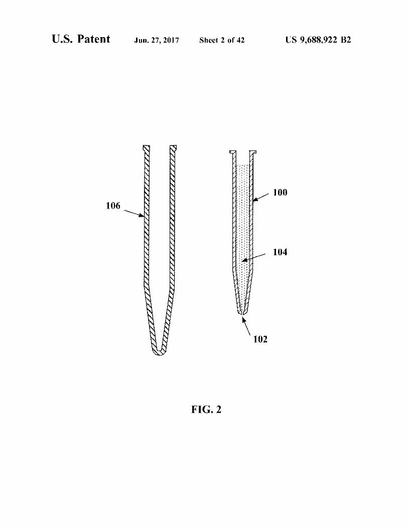
device. The second system may have a clam shell-likeformation which may further have a first portion 302 and asecond portion 304. The first portion 302 and the secondportion 304, depending on the orientation of the device, maybe the top and the bottom of the separation device of thesecond system 300. In FIG. 4, the first portion 302 and the
12
second portion 304 of the second system fit together with theaid of, for example, an aligning pivot 305. The second
15 portion 304 may have cavities 306, wherein each cavity 306may form an aperture 308 where the first portion 302 andsecond portion 304 of the second system come together.FIG. 8 illustrates how the cavities 306 may align radially.
For example, the cavities 306 may be roughly semi conical20 with an opening that is wider toward the center 402 of the
second portion 304 of the second system 300 and narrows asit reaches the perimeter 404. While the cavities 306 areillustrated as semi conical in FIG. 9, other shapes may beused.
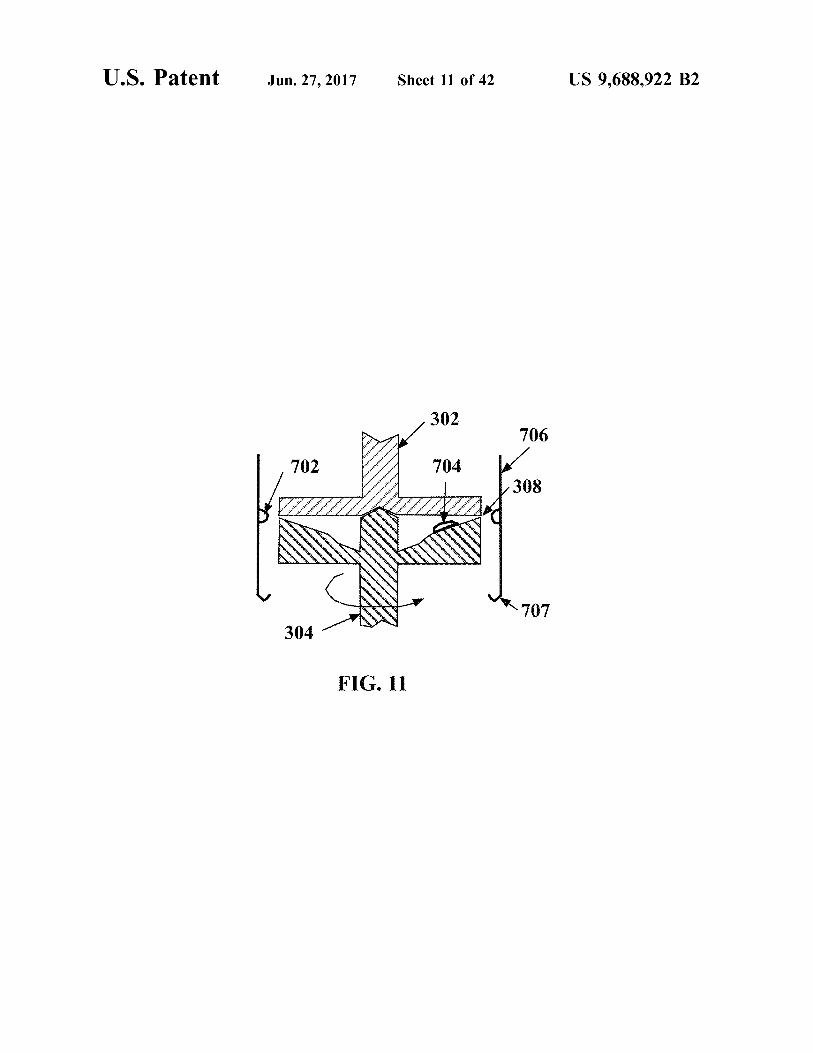
25 The second system 300 may also include a liquid collector706, as shown in FIG. 11, which may be cylindrical, or anyother shape. For example, the liquid collector may or maynot approximate the shape of the second system separationdevice 300. The liquid collector 706 may include a gutter
30 707 which may collect and funnel the liquid to a collectionreservoir. The gutter 707 may be located on the lower edgeof the liquid collector, or may be located in any otherlocation. The liquid collector 706 may be arranged with thesecond system separation device 300 such that the second
35 system separation device 300 may be raised and loweredinto position with the liquid collector 706 as the separationprocess proceeds.FIGS. 10-13 illustrate how the process for extracting
liquids from solid particles might be adapted for the second40 system 300 separation device described above. The solids-
liquids mixture 602 may be placed inside the cavities 306 inthe second system 300. In FIG. 10 the solids-liquids mixture602 may be heated before loading, during loading, or afterloading into the separation device of the second system 300.
45 The second system 300 may be lowered into a liquidcollector 706 and may be spun as shown in FIG. 11.Spinning may cause the liquid 702 to separate from the solidparticles 704. The liquid 702 may exit apertures 308, andmay accumulate, for example, on the liquid collector 706,
5o and/or in a gutter 707. The solid particles 704 may remaininside the closed second system 300. The apertures 308 maybe funnel shaped, with the diameter of the aperture decreas-ing as it reaches the termination point of the aperture wherethe liquid escapes.
55 After separation has been accomplished, the liquid col-lector 706 may be raised, and the second system 300 may beopened as shown in FIG. 12. The first portion 302 andsecond portion 304 may be spun such that the solid particlesare spun out of the cavities 306. A solid particles collector
60 802 may be used to catch the solid particles 704.The second system 300 may then be reused. A new load
of heated or unheated solids-liquids mixture 602 may beinserted into the second system 300 and the liquid collector706 may replaced into a position that will allow it to capture
65 extracted liquids. The second system 300 may be closed andrespun, as shown in FIG. 13, continuing the cycle. Alterna-tively, the cycle may terminate after one use. The optimal

US 9,688,922 B213
aperture 308 size for removing oil from Athabsca oil sandsis approximately 0.40-1.50 mm, 0.45-1.35 mm, 0.80-1.30mm, and/or 9.90-1.20 mm. However, other sizes may beused.
FIG. 14 is a cross-sectional view of a third system 1010,the confining portion 1030 of which may have a cycloneformation. The third system 1010 may include a confiningportion 1030 and a collecting portion 1026. The third system1010 may also include a coaxial piston 1014 and a centralshaft 1011 which may be supported by a bearing 1012. Thethird system 1010 may also include a feed tube 1016. Theconfining portion 1030 may be assembled inside of thecollecting portion 1026, for example, in a nested conforma-tion. The feed tube 1016 may be assembled inside of theconfining portion 1030. In one example, the feed tube 1016may be assembled with the central shaft 1011.The confining portion 1030 may be approximately conical
in shape. The confining portion 1030 may have a top 1050and a bottom 1055. The top 1050 of the confining portion1030 may be dimensioned larger than the bottom 1055 of theconfining portion.The confining portion 1030 may have walls 1018. The
walls 1018 may have an interior face 1032 and an exteriorface 1034. The interior face 1032 of the walls 1018 of theconfining portion 1030 may have baffles 1020 locatedthereon. The baffles 1020 may be continuous with theinterior face 1032. The baffles 1020 may be arranged in ascrew-thread-like fashion along the interior face 1032 of thewalls 1018 of the confining portion 1030 of the third system1010. FIG. 14 shows a cross section view of the third system1010. Here, the baffles 1020 are shown in cross sectionprotruding from the interior face 1032 of the walls 1018 ofthe confining portion 1030. FIG. 14a is an exploded viewfurther showing the baffles 1020 protruding from the interiorface 1032 of the walls 1018 of the confining portion 1030.The baffles 1020 may be continuous. The baffles 1020 maybe arranged radially.
FIG. 15 shows a perspective view of the third system1010. Here, the baffles 1020 are shown protruding from theinterior face 1032 of the confining portion 1030. The col-lecting portion 1026 is shown in cut-away. FIG. 15 providesan illustration of the screw-thread-like fashion with whichthe baffles 1020 are assembled with the interior face 1032 ofthe confining portion 1030.The walls 1018 of the third system 1010 may further
include small apertures FIG. 3, 102 or apertures 1022. Anexploded exemplary view of a wall 1018 including apertures1022 is illustrated in FIG. 14a. Alternatively or additionally,the apertures FIG. 3, 102 may be funnel shaped as shown inFIG. 3.The collecting portion 1026 of the third system 1010 may
be cylindrical or any other shape.FIGS. 14-15 illustrate how the process for extracting
liquids from solid particles might be adapted for the thirdsystem 1010 described above. The solids-liquids mixture602, for example, oil sands, may be heated prior to loadingor may be heated during loading or, alternatively, in the thirdsystem 1010. For example, the solids-liquids mixture 602may be heated in the feed tube 1016, in the confining portion1030 (which may be cyclone in shape), or in a retaining tankattached to the feed tube, and etc.; alternatively, it may beheated prior to being loaded into the feed tube 1016.The heated or unheated solids-liquids mixture 602 may be
loaded into the third system 1010 by a feed tube 1016. Thefeed tube 1016 may be centrally located. A coaxial piston1014 may push an amount of a heated solids-liquids mixture602 down a feed tube 1016 and out the bottom of the feed
14tube 1016 into the confining portion. A centrifugal force maybe applied to the confining portion 1030. The confiningportion 1030 may be rotated co-axially as shown in FIG. 15.The heated solids-liquids mixture 602 may be centrifugally
5 forced outward and upward along the baffles 1020 on theinterior face 1032 of the wall 1018 of the confining portion1030.The liquid 702 may escape through the small apertures
1022, which may have a diameter of approximately 0.40-10 1.50 mm, 0.45-1.35 mm, 0.80-1.30 mm or more preferably
0-0.90-1.20 mm. The apertures 1022 may be dimensioned asshown in FIG. 3. Solid particles 704 may be centrifugallypushed upward and eventually go over the top of the third
15 system 1010 (as demonstrated by FIG. 14 arrow 1036)where it may be collected and recycled, disposed of orotherwise. The liquid 702 that is extracted may be collectedby the collecting portion 1026, for example, by accumulat-ing at the bottom 1028. This may be a continuous process by
20 which the feed tube 1016 continually feeds solids-liquidsmixture 602 into the third system 1010 to replace the liquidand solids that are removed.FIG. 16 shows a fourth system which may be formed of
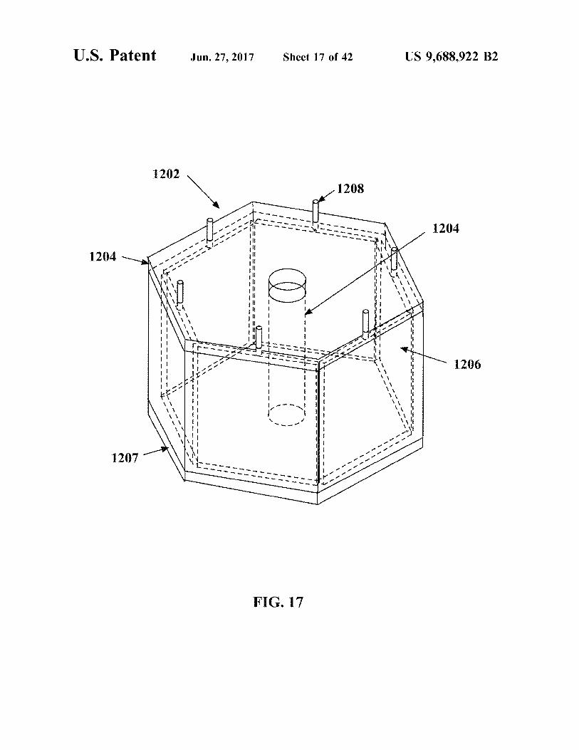
rotating planes. The fourth system may have a chamber25 1202. This device may be self-cleaning. As shown in FIG.
17, the rotating planes system may have a top plate 1205 anda bottom plate 1207, which may be coaxially mounted witha main shaft 1204 so that the top plate 1205 can be raised andthe bottom plate 1207 can be lowered. The chamber may be
30 formed of multiple chamber walls 1206. The chamber wallsmay have aperture 1402 through which liquid may beextracted from the liquids-solid mixture. The chamber 1202can take many shapes depending on the number of walls1206, such as a hexagonal shape as shown in FIGS. 16-20.
35 Each of the walls 1206 may be centrally pivoted 1208. Thechamber 1202 rotating planes separator may have at leasttwo configurations, for example, a closed configuration (see,e.g., FIGS. 16, 17, 20a, 20c, 20e) and an open configuration(see, e.g., FIGS. 20b, 20d). In the closed configuration, the
40 walls 1206 may be sealed by outer 1304 and inner 1306splines as shown in FIG. 19. The apertures 1402 in thechamber walls 1206 may have a diameter of approximately0.40-1.50 mm, 0.45-1.35 mm, 0.80-1.30 mm, or 0.90-1.20mm. The apertures 1402 may have a diameter that decreases
45 from the originating point on the inner face of the wall to theterminating point on the outside face of the wall, where theoil escapes. (See, e.g., FIG. 3) In the open configuration, thewalls 1206 may be rotated on their pivot point such that theyare no longer in contact. (See, e.g., FIGS. 20b, 20d)
50 In operation, heated solids-liquids mixture 602 may beplaced in the chamber and the chamber may be spun, asshown in the top view in FIG. 20. The liquid 702 separatesfrom the solid particles 704 and may be collected by a liquidcollector 1504 surrounding the chamber. The liquid collector
55 1504 may be, for example, cylindrical or may otherwiseapproximate the shape of the chamber 1202. Alternatively,the liquid collector 1504 may be of any other shape orformat. When separation has been completed and rotationhas stopped, the bottom plate may be lowered. The top plate
60 may be raised and the liquid collector 1504 may be raisedeven more, so that its bottom is above the top of the chamberwalls 1206, which are rotated as shown in the second step inFIG. 20b.
Next, the chamber walls 1206 may be locked by the65 splines at for example 180° so that the apertures face toward
the center of the chamber. The chamber 1202 may be spunto cleanse the remaining solid particles 704. The solid

US 9,688,922 B215
particles 704 removed from the chamber may be caught bya solid-particle collector 1506 as shown in the third step inFIG. 20c.
After cleaning, the chamber 1202 may be stopped; thesolid-particle collector 1506 may be lowered away from thechamber 1202. The chamber 1202 may be returned to aclosed position by rotating the walls 1206 180° as shown inthe fourth step in FIG. 20d. The bottom plate may rise tocomplete the closed conformation. At that point, moresolids-liquids mixture 602 may be placed inside the cham-ber, and the top may be lowered and the liquid collector1504 raised into conformation for the next round of pro-cessing.
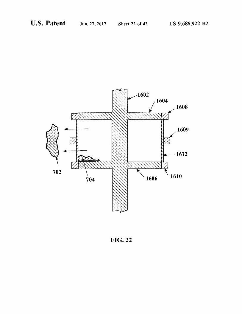
FIG. 21 shows a fifth system 1600 which may be a doublepiston type of a separator. The fifth system 1600 may havea rotating main shaft 1602. The rotating main shaft 1602may further have an attached a top piston 1604 and a bottompiston 1606. The fifth system 1600 may also include afiltering portion 1607 which may have a top band 1608, abottom band 1610 and a screen 1612.The screen 1612 may be made of any material and may be
of sufficient strength to withstand centrifugal force andretain the solid particles. The screen may be supported bybands 1608, 1609 and 1610 as illustrated in FIG. 21. Thescreen 1612 may have openings or apertures, which may bedimensioned to retain the solid particles 704 and let theliquid 702 through, as shown in FIG. 21. For separation ofoil from Athabasca oil sands, the aperture may have adiameter of approximately 0.40-1.50 mm, 0.45-1.35 mm,0.80-1.30 mm, or 0.90-1.20 mm. As stated above, theaperture size may vary depending on the properties of theliquid-solid material and the efficiency of the separation mayvary as a function of aperture size.The attached top piston 1604 and bottom piston 1606 may
be separated by a distance such that, in the closed position,the top piston 1604 is even with the top band 1608 of thefiltering portion 1607, and the bottom piston 1606 is evenwith the bottom band 1610 of the filtering portion 1607.
In operation, the top piston 1604 and bottom piston 1606may be raised enough to introduce the solids-liquids mixture602 as shown in the first step in FIG. 23. The pistons maybe lowered and aligned with the filtering portion 1607. Theapparatus may be spun, as shown in the second step 1802 inFIG. 23b. Heat may be applied to the mixture prior toloading or the apparatus may be heated before or duringspinning.
During spinning the solid particles 704 may be restrainedby the screen 1612; the liquid 702 may pass through thescreen 1612 and may be captured by the liquid collector1804.
After the spinning is completed and extraction has con-cluded, the apparatus may be cleaned as follows. The pistonsmay be lowered until the bottom edge of the top of the filteris even with the bottom edge of bottom band 1610, as shownin the third step in FIG. 23c. The solid particles may beremoved from the piston by spinning such that the solidparticles 704 leave the fifth system 1600 and are collected bya solid-particle collector 1806.
After cleaning, the process may be repeated. For example,a new batch of heated or unheated solids-liquids mixture 602may be inserted into the double piston system, as shown inthe fourth step in FIG. 23d.
While various systems of the invention have beendescribed, it will be apparent to those of ordinary skill in theart that many more systems and implementations are pos-sible that are within the scope of the invention.
16FIG. 23 shows a cross sectional view of a sixth system
2100, which may be a centrifugal type of separator. Thesixth system 2100 may have a rotor 2104. The rotor 2104may spin a tube 2102. The sixth system 2100 may include
5 multiple tubes 2102 depending on the size of the tube 2102and the rotor 2104. The tube 2102, may include multipleparts. For example, the tube 2102 may have a first part 2216and a second part 2118. The multiple parts may be con-nected, such as by a hinge 2114 or otherwise. When the first
10 part 2116 and the second part 2118 are in contact, they mayform a tube 2102. The tube 2102 may include an aperture2106 at one end. The aperture 2106 may facilitate separationof liquids, such as oil or water, from solids, such as sand or
15 shale, by retaining solids within the tube 2102. The sixthsystem 2100 may also include an extractor 2108. As shownin FIG. 26, the extractor 2108 may remove the tube 2102from the rotor 2104, may split the tube 2102 into its first part2116 and second part 2118, and may spin the tube 2102 to
20 remove the solid particles.The sixth system 2100 may include a liquid collector
2202, as shown in FIG. 25, which may be any shape capableof containing the liquid, such as a cylinder, rectangle, orhexagon.
25 The process for extracting liquids from solid particlesmay be adapted for the sixth system 2100, described above,by placing a solids-liquids mixture in the tube 2102, whichmay be placed in the rotor 2104. The solids-liquids mixturemay be heated before, during, or after placement in the tube
30 2102. The solids-liquids mixture, for example oil shale or oilsands, may be heated to approximately 25° C.-200° C., 50°C.-175° C., 75° C.-150° C., 95° C.-125° C., and preferablyapproximately 92° C.-110° C. and more preferably approxi-
35 mately 94° C. (e.g., in a water bath). The tube 2102 may beinserted into the rotor 2104 and spun perpendicular to thelong axis of the tube 2102. The tube 2102 may be spun toapproximately 500 rpm to 10,000 rpm. Spinning may causethe liquid to separate from the solid particles. The tube 2102
40 may be spun for approximately 15 seconds to 20 minutes.The liquid may exit the aperture 2106 and may accumulate,for example, on the liquid collector 2202. The optimumaperture 2106 size for extracting oil from Athabasca oilsands may be, for example, approximately 0.40-1.50 mm,
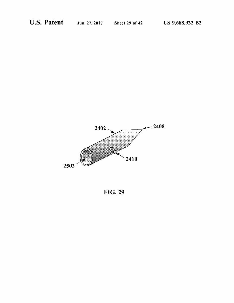
45 0.45-1.35 mm, 0.80-1.30 mm, or preferably approximately0.85-1.10 mm. The sixth system 2100 may then be reusedwith a new solids-liquids mixture.FIGS. 27-31 show a seventh system 2400 which may be
a centrifugal type of separator. The seventh system 240050 may have a rotor with multiple parts. The first part of the
rotor 2404 may attach to a power generator or other sourceof power. The first part of the rotor 2404 may have an axialopening 2506. The second part of the rotor 2504 mayconstrain the movement of a tube 2402 within the first part
55 of the rotor 2404, as shown in FIG. 28, a cross-sectionalview. The rotor 2404, 2504 may spin a tube 2402. Theseventh system 2400 may include multiple tubes 2402depending on the size of the tube 2402 and the rotor 2404,2504. The tube 2402 may include one open end 2502, as
60 shown in FIG. 28. The tube 2402 may include a smalleraperture 2408 at the other end. The aperture 2408 mayfacilitate separation of liquids, such as oil or water, fromsolids, such as sand or shale, by retaining solids within thetube 2402. The tube 2402 may also include a pivot point
65 2410, such as an axle, along the length of the tube 2402 thatmay be perpendicular to the tube length, as shown in FIG.29.

US 9,688,922 B217
The seventh system 2400 may include a liquid collector2702, as shown in FIG. 30 and FIG. 31, which may be anyshape capable of containing the liquid, such as a cylinder,rectangle, or hexagon.The process for extracting liquids from solid particles
may be adapted for the seventh system 2400, describedabove, by placing a solids-liquids mixture in the tube 2402,which may be placed in the first part of the rotor 2404 andsecured in place by the second part of the rotor 2504. Thesolids-liquids mixture may be heated before, during, or afterplacement in the tube 2402. The solids-liquids mixture, forexample oil shale or oil sands, may be heated to approxi-mately 25° C.-200° C., 50° C.-175° C., 75° C.-150° C., 95°C.-125° C., and preferably approximately 92° C.-110° C.and more preferably approximately 94° C. (e.g., in a waterbath). The tube 2402 may be inserted into the first part of therotor 2404, as shown in FIG. 30, and spun perpendicular tothe long axis of the tube 2402. The tube 2402 may be spunto approximately 500 rpm to 10,000 rpm. The tube 2402may be spun for approximately 15 seconds to 20 minutes.Spinning may cause the liquid to separate from the solidparticles. The liquid may exit the aperture 2408 and mayaccumulate, for example, on the liquid collector 2702. Theoptimum aperture 2408 size for extracting oil from Atha-basca oil sands may be, for example, approximately 0.40-1.50 mm, 0.45-1.35 mm, 0.80-1.30 mm, or preferablyapproximately 0.85-1.10 mm. Once the liquid has left thetube 2402, the second part of the rotor 2504 may be movedto allow the tube 2402 to pivot along the pivot point 2410.If the tube 2410 is spun, the remaining solid particles mayexit the open end 2502 of the tube 2402, as shown in FIG.31. The liquid collector 2702 may be changed to collect thesolid particles. The seventh system 2400 may then be reusedwith a new solids-liquids mixture.FIG. 32 shows an eighth system 2900, which may be a
centrifugal type of separator. The eighth system 2900 mayinclude a rotor 2904. The rotor 2904 may spin a tube 2902.The eighth system 2900 may include multiple tubes 2902depending on the size of the tube 2902 and the rotor 2904.The tube 2902 may be open on one end 2910 and mayinclude a smaller aperture 2906 at the other end. Theaperture 2906 may facilitate separation of liquids, such as oilor water, from solids, such as sand or shale, by retainingsolids within the tube 2902. The tube 2902 may include alockable pivot point 2908, such as a geared axle, along thelength of the tube that may be perpendicular to the tubelength.The eighth system 2900 may include a liquid collector
2912, as shown in FIG. 32, which may be any shape capableof containing the liquid, such as a cylinder, rectangle, orhexagon.The process for extracting liquids from solid particles
may be adapted for the eighth system 2900, described above,by placing a solids-liquids mixture in the tube 2902, whichmay be positioned within the rotor 2904 and secured in placeby the lockable pivot point 2908. The solids-liquids mixturemay be heated before, during, or after placement in the tube2902. The solids-liquids mixture, for example oil shale or oilsands, may be heated to approximately 25° C.-200° C., 50°C.-175° C., 75° C.-150° C., 95° C.-125° C., and preferablyapproximately 92° C.-110° C. and more preferably approxi-mately 94° C. (e.g., in a water bath). The rotor 2904 mayspin the tube 2902 perpendicular to the long axis of the tube2902. The tube 2902 may be spun to approximately 500 rpmto 10,000 rpm. The tube 2902 may be spun for approxi-mately 15 seconds to 20 minutes. Spinning may cause theliquid to separate from the solid particles. The liquid may
18exit the aperture 2906 and may accumulate, for example, onthe liquid collector 2912. The optimum aperture 2906 sizefor extracting oil from Athabasca oil sands may be, forexample, approximately 0.40-1.50 mm, 0.45-1.35 mm, 0.80-
5 1.30 mm, or preferably approximately 0.85-1.10 mm. Oncethe liquid has left the tube 2902, the lockable pivot point2908 may allow the tube 2902 to pivot such that theremaining solid particles may exit the open end of the tube2902 if it is spun. The liquid collector 2912 may be changed
io to collect the remaining solid particles. The eighth system2900 may then be reused with a new solids-liquids mixture.
FIG. 33 shows a ninth system 3000, which may be acentrifugal type of separator. An exemplary cross-sectionalperspective view of the ninth system 3000 is shown in FIG.
15 34. The ninth system 3000 may include a tube 3002. Thetube 3002 may be open on one end 3010. The tube 3002 mayinclude a smaller aperture 3008 at the other end. Theaperture 3008 may facilitate separation of liquids 3304, suchas oil or water, from solid particles 3306, such as sand or
20 shale, by retaining solid particles 3306 within the tube 3002if it is spun. The ninth system 3000 may include a disk 3004.The disk 3004 may be contained within the tube 3002. Thedisk 3004 may be held in place such that the disk 3004 isperpendicular to the length of the tube 3002, as shown in
25 FIG. 33 and FIG. 34. The disk 3004 may also be moved byrods 3006 such that the disk 3004 is parallel to the length ofthe tube 3002, as shown in the front view in FIG. 35a andin the side view in FIG. 35b.The process for extracting liquids 3304 from solid par-
30 ticles 3306 may be adapted for the ninth system 3000,described above, by placing a solids-liquids mixture 3302 inthe tube 3002 with the disk 3004 positioned parallel to thelength of the tube 3002, as shown in front view in FIG. 36aand inside view in FIG. 36b. The solids-liquids mixture 3302
35 may be heated before, during, or after placement in the tube3002. The solids-liquids mixture 3302, for example oil shaleor oil sands, may be heated to approximately 25° C.-200° C.,50° C.-175° C., 75° C.-150° C., 95° C.-125° C., and pref-erably approximately 92° C.-110° C. and more preferably
4o approximately 94° C. (e.g., in a water bath). Spinning thetube 3002 perpendicular to the long axis of the tube 3002may cause the liquid 3304 to separate from the solidparticles 3306. The tube 3002 may be spun to approximately500 rpm to 10,000 rpm. The tube 3002 may be spun for
45 approximately 15 seconds to 20 minutes. The liquid 3304may exit the aperture 3008 for collection later. The optimumaperture 3008 size for extracting oil from Athabasca oilsands may be, for example, approximately 0.40-1.50 mm,0.45-1.35 mm, 0.80-1.30 mm, or preferably approximately
50 0.85-1.10 mm. Once the liquid 3304 has left the tube 3002,the disk 3004 may be repositioned perpendicular to thelength of the tube 3002 and removed from the tube 3002, asshown in FIG. 36c, extracting the remaining solid particles3306 as it is removed. The ninth system 3000 may then be
55 reused with a new solids-liquids mixture 3302, as shown inFIG. 36d.FIGS. 37-38 show a tenth system 3400, which may have
a cylindrical formation. The tenth system 3400 may includea shaft 3406. The shaft 3406 may be placed within a first
60 cylinder 3402. The shaft 3406 may be angled to allow themovement of a solids-liquids mixture 3504 down the insideof the first cylinder 3402 by gravity. The first cylinder 3402may include apertures 3416. An exploded exemplary viewof the first cylinder 3402 including apertures 3416 is illus-
65 trated in FIG. 38a. The apertures 3416 may facilitate theseparation of liquids 3502, such as oil or water, from solids,such as sand or shale, by retaining solid particles 3506
US 9,688,922 B219
within the first cylinder 3402. The first cylinder 3402 may beplaced within a second cylinder 3404. As shown in FIG. 37,the second cylinder 3404 may include a protrusion 3412.The protrusion 3412 may collect and direct the liquid 3502to a collection point 3414.The process for extracting liquids 3502 from solid par-
ticles 3506 may be adapted for the tenth system 3400,described above, by placing a solids-liquids mixture 3504 onthe inside of the spinning first cylinder 3402 and allowing itto travel along the surface of the first cylinder 3402 bygravity. The solids-liquids mixture 3504 may be heatedbefore, during, or after placement in the first cylinder 3402.The solids-liquids mixture 3504, for example oil shale or oilsands, may be heated to approximately 25° C.-200° C., 50°C.-175° C., 75° C.-150° C., 95° C.-125° C., and preferablyapproximately 92° C.-110° C. and more preferably approxi-mately 94° C. (e.g., in a water bath). Spinning the firstcylinder 3402 may cause the liquid 3502 to separate from thesolid particles 3506. The first cylinder 3402 may be spun toapproximately 500 rpm to 10,000 rpm. The first cylinder3402 may be spun for approximately 15 seconds to 20minutes. The liquid 3502 may exit the first cylinder 3402through the apertures 3416. The optimum aperture 3416 sizefor extracting oil from Athabasca oil sands may be, forexample, approximately 0.40-1.50 mm, 0.45-1.35 mm, 0.80-1.30 mm, or preferably approximately 0.85-1.10 mm. Theliquid 3502 may accumulate on the second cylinder 3404and may be contained by the protrusion 3412 and drained atthe collection point 3414. A person skilled in the art may beable to adjust the angle of the first cylinder 3402, therotational rate of the first cylinder 3402, and the feed rate ofthe solids-liquids mixture 3504 such that a majority of theliquid 3502 may be removed by the time the solids-liquidsmixture 3504 reaches the lower end of the first cylinder3402. The tenth system 3400 may be used in a continuousprocess.FIGS. 39-40 show an eleventh system 3600, which may
have a cylindrical formation. The eleventh system 3600 mayinclude a rotating screw shaft 3606. The rotating screw shaft3606 may be placed within a first cylinder 3602. The rotatingscrew shaft 3606 may facilitate the separation of liquids3702, such as oil or water, from solids 3704, such as sand orshale, by retaining solids 3704 within the first cylinder 3602.The first cylinder 3602 may include apertures 3614. Anexploded exemplary view of the first cylinder 3602 includ-ing apertures 3614 is illustrated in FIG. 40a. The apertures3614 may facilitate the separation of liquids 3702, such asoil or water, from solids 3704, such as sand or shale, byretaining solids 3704 within the first cylinder 3602. The firstcylinder 3602 may be placed within a second cylinder 3604.As shown in FIG. 40, the second cylinder 3604 may includea protrusion 3610. The protrusion 3610 may collect anddirect the liquid to a collection point 3612.The process for extracting liquids 3702 from solid par-
ticles 3704 may be adapted for the eleventh system 3600,described above, by placing a solids-liquids mixture 3608 onthe inside of the spinning first cylinder 3602 and using therotating screw shaft 3606 to move the solids-liquids mixture3608 along the inner surface of the first cylinder 3602. Thesolids-liquids mixture 3608 may be heated before, during, orafter placement in the first cylinder 3602. The solids-liquidsmixture 3608, for example oil shale or oil sands, may beheated to approximately 25° C.-200° C., 50° C.-175° C., 75°C.-150° C., 95° C.-125° C., and preferably approximately92° C.-110° C. and more preferably approximately 94° C.(e.g., in a water bath). Spinning the first cylinder 3602 maycause the liquid 3702 to separate from the solids 3704. The
20first cylinder 3602 may be spun to approximately 500 rpmto 10,000 rpm. The first cylinder 3602 may be spun forapproximately 15 seconds to 20 minutes. The liquid 3702may exit the first cylinder 3602 through the apertures 3614.
5 The optimum aperture 3614 size for extracting oil fromAthabasca oil sands may be, for example, approximately0.40-1.50 mm, 0.45-1.35 mm, 0.80-1.30 mm, or preferablyapproximately 0.85-1.10 mm. The liquid 3702 may accu-mulate on the second cylinder 3604 and maybe contained by
io the protrusion 3610 and drained at the collection point 3612.Aperson skilled in the art may be able to adjust the rotationalrate of the screw shaft 3606, the feed rate of the solids-liquids mixture 3608, and the rotational rate of the firstcylinder 3602 such that a majority of the liquid 3702 may be
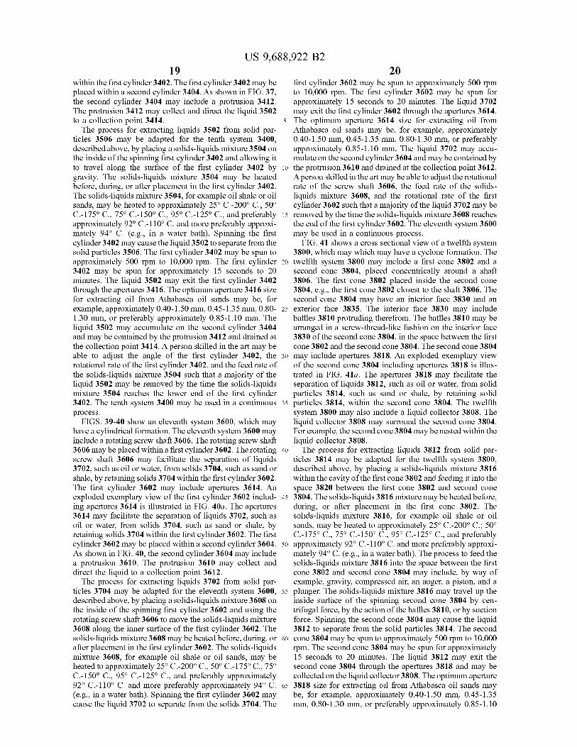
15 removed by the time the solids-liquids mixture 3608 reachesthe end of the first cylinder 3602. The eleventh system 3600may be used in a continuous process.FIG. 41 shows a cross sectional view of a twelfth system
3800, which may which may have a cyclone formation. The20 twelfth system 3800 may include a first cone 3802 and a
second cone 3804, placed concentrically around a shaft3806. The first cone 3802 placed inside the second cone3804, e.g., the first cone 3802 closest to the shaft 3806. Thesecond cone 3804 may have an interior face 3830 and an
25 exterior face 3835. The interior face 3830 may includebaffles 3810 protruding therefrom. The baffles 3810 may bearranged in a screw-thread-like fashion on the interior face3830 of the second cone 3804, in the space between the firstcone 3802 and the second cone 3804. The second cone 3804
30 may include apertures 3818. An exploded exemplary viewof the second cone 3804 including apertures 3818 is illus-trated in FIG. 41a. The apertures 3818 may facilitate theseparation of liquids 3812, such as oil or water, from solidparticles 3814, such as sand or shale, by retaining solid
35 particles 3814, within the second cone 3804. The twelfthsystem 3800 may also include a liquid collector 3808. Theliquid collector 3808 may surround the second cone 3804.For example, the second cone 3804 may be nested within theliquid collector 3808.
40 The process for extracting liquids 3812 from solid par-ticles 3814 may be adapted for the twelfth system 3800,described above, by placing a solids-liquids mixture 3816within the cavity of the first cone 3802 and feeding it into thespace 3820 between the first cone 3802 and second cone
45 3804. The solids-liquids 3816 mixture may be heated before,during, or after placement in the first cone 3802. Thesolids-liquids mixture 3816, for example oil shale or oilsands, may be heated to approximately 25° C.-200° C.; 50°C.-175° C., 75° C.-150° C., 95° C.-125° C., and preferably
5o approximately 92° C.-110° C. and more preferably approxi-mately 94° C. (e.g., in a water bath). The process to feed thesolids-liquids mixture 3816 into the space between the firstcone 3802 and second cone 3804 may include, by way ofexample, gravity, compressed air, an auger, a piston, and a
55 plunger. The solids-liquids mixture 3816 may travel up theinside surface of the spinning second cone 3804 by cen-trifugal force, by the action of the baffles 3810, or by suctionforce. Spinning the second cone 3804 may cause the liquid3812 to separate from the solid particles 3814. The second
60 cone 3804 may be spun to approximately 500 rpm to 10,000rpm. The second cone 3804 may be spun for approximately15 seconds to 20 minutes. The liquid 3812 may exit thesecond cone 3804 through the apertures 3818 and may becollected on the liquid collector 3808. The optimum aperture
65 3818 size for extracting oil from Athabasca oil sands maybe, for example, approximately 0.40-1.50 mm, 0.45-1.35mm, 0.80-1.30 mm, or preferably approximately 0.85-1.10

US 9,688,922 B221
mm. The remaining solid particles 3814 may exit space 3822between the first cone 3802 and second cone 3804 near thetop of the second cone 3804. A person skilled in the art maybe able to adjust the angle of the first cone 3802 and secondcone 3804, the rotational rate of the second cone 3804, thefeed rate of the solids-liquids mixture 3816, and the place-ment of the baffles 3810 such that a majority of the liquid3812 may be removed by the time the solids-liquids mixture3816 reaches the top of the second cone 3804. The twelfthsystem 3800 may be used in a continuous process.
FIG. 42 shows a cross sectional view of a thirteenthsystem 3900, which may include a cylindrical formation.The thirteenth system may include a vertical first cylinder3902 and a vertical second cylinder 3904, placed concen-trically around a shaft 3906. The first cylinder 3902 mayhave a first face 3930 and a second face 3935. The secondface 3935 of the first cylinder 3902 may have baffles 3910protruding therefrom. The second cylinder 3904 may have afirst face 3940 and a second face 3945. The first face 3940of the second cylinder 3904 may have baffles 3910 protrud-ing therefrom. The first face 3940 of the second cylinder3904 may be positioned facing the second face 3935 of thefirst cylinder 3902.The baffles 3910 may be positioned in the space between
the first cylinder 3902 and the second cylinder 3904. Thebaffles 3910 may control the movement of a solids-liquidsmixture 3912. The second cylinder 3904 may include aper-tures 3918. An exploded exemplary view of the secondcylinder 3904 including apertures 3918 is illustrated in FIG.42 a. The apertures 3918 may facilitate the separation ofliquids 3914, such as oil or water, from solid particles 3916,such as sand or shale, by retaining solid particles 3916within the second cylinder 3904. The twelfth system mayalso include a liquid collector 3908. The apertures 3918 maybe dimensioned as shown and described in FIG. 3. Theliquid collector 3908 may surround the second cylinder3904. For example, the second cylinder 3904 may be nestedwithin the liquid collector 3908.The process for extracting liquids 3914 from solid par-
ticles 3916 may be adapted for the thirteenth system 3900,described above, by placing a solids-liquids mixture 3912 inthe space 3920 between the rotating first cylinder 3902 androtating second cylinder 3904. The solids-liquids mixture3912 may be heated before, during, or after placement in thespace between the first cylinder 3902 and second cylinder3904. The solids-liquids mixture 3912, for example oil shaleor oil sands, may be heated to approximately 25° C.-200° C.,50° C.-175° C., 75° C.-150° C., 95° C.-125° C., and pref-erably approximately 92° C.-110° C. and more preferablyapproximately 94° C. (e.g., in a water bath). The size andplacement of the baffles 3910 may adjust the movement ofthe solids-liquids mixture 3912. Spinning the first cylinder3902 and second cylinder 3904 may cause the liquid 3914 toseparate from the solid particles 3916. The first cylinder3902 and second cylinder 3904 may be spun to approxi-mately 500 rpm to 10,000 rpm. The second cylinder 3904may be spun for approximately 15 seconds to 20 minutes.The liquid 3914 may exit the second cylinder 3904 throughthe apertures 3918 and may be collected on the liquidcollector 3908. The optimum aperture 3918 size for extract-ing oil from Athabasca oil sands may be, for example,approximately 0.40-1.50 mm, 0.45-1.35 mm, 0.80-1.30 mm,or preferably approximately 0.85-1.10 mm. The remainingsolid particles 3916 may exit the space 3922 between thefirst cylinder 3902 and second cylinder 3904 near the bottomof the second cylinder 3904 alternatively or additionally, theremaining solid particles 3916 may exit the space 3922
22between the first cylinder 3902 and the second cylinder 3904near or at the top of the second cylinder 3904. The space3922 between the first cylinder 3902 and the second cylinder3904 that may allow the solid particles to exit may be
5 continuous. A person skilled in the art may be able to adjustthe rotational rate of the first cylinder 3902 and secondcylinder 3904, the feed rate of the solids-liquids mixture3912, and the placement of the baffles 3910 such that amajority of the liquid 3914 may be removed by the time the
io solids-liquids mixture 3912 reaches the bottom of the secondcylinder 3904. The thirteenth system 3900 may be used in acontinuous process.A method for separating oil from oil sands comprising:
heating the oils sands; spinning the heated oil sands; con-15 fining mechanically sand particles present in the oils sands
away from the oil; and recovering the oil substantially freeof the sand. Further, the oil sands heated to approximately25-200 degrees C. The oils sands heated to approximately 92degrees C. to 110 degrees C. The particles are confined away
20 from the oil by an aperture. The aperture is about 0.40 toabout 1.5 mm in diameter. The aperture is about 0.80 toabout 1.20 mm in diameter. The oil sands are subjected tocentrifugal force. The oil is extracted from the oil sandswithout the use of chemicals.
25 A separation device for separating liquids from a solidparticulate material, the separation device comprising: astructure for confining the sand particles, a structure forrecovering the oil; and where the separation device issubjected to centrifugal force.
30 A separation device for separating liquids from a solidparticulate material, the separation device comprising: astructure for confining the sand particles, a structure forrecovering the oil; and where the separation device issubjected to centrifugal force. The structure for confining
35 sand particles comprises a first tube and a second tube; thefirst tube and the second tube being dimensioned such thatthe first tube fits inside the second tube; the first tubeincluding at least one aperture sized smaller than the oilsand; the first tube for confining the sand particles mechani-
40 cally; and the second tube for recovering the oil.A separation device for separating liquids from a solid
particulate material, the separation device comprising: astructure for confining the sand particles, a structure forrecovering the oil; and where the separation device is
45 subjected to centrifugal force. The structure for confining theparticles has a clam shell formation including a first portionand a second portion; the first portion and the secondportions being dimensioned to fit together with an aligningpivot; the first portion including at least one cavity; the
50 second portion including at least one cavity that mirrors thecavity of the first portion; and where, when the first portionand the second portion are fit together, the cavity in the firstportion and the cavity in the second portion align to formone cavity; and the cavities terminate to form an aperture
55 through which oil escapes; and the aperture is dimensionedto confine the sand particles within the cavity.A separation device for separating liquids from a solid
particulate material, the separation device comprising: astructure for confining the sand particles, a structure for
6o recovering the oil; and where the separation device issubjected to centrifugal force. The structure for confining theparticles has a conical formation with one or more walls, thewalls including apertures, the walls also including baffleslocated along the interior of the conical separator, the baffles
65 being continuous and arranged radially, and wherein theseparation device further comprises a structure for recover-ing the oil.

US 9,688,922 B223
A separation device for separating liquids from a solidparticulate material, the separation device comprising: astructure for confining the sand particles, a structure forrecovering the oil; and where the separation device issubjected to centrifugal force. The structure for confining theparticles includes three or more planes, the planes beingfreely rotatable about a central axis; the central axis havinga pivot; the planes being oriented so that they form walls ofa closed chamber when rotated to a closed formation; theplanes further including apertures through which oilescapes; and a structure for recovering oil.A separation device for separating liquids from a solid
particulate material, the separation device comprising: astructure for confining the sand particles, a structure forrecovering the oil; and where the separation device issubjected to centrifugal force. A rotating main shaft; a toppiston and a bottom piston removably attached to the mainshaft; a filtering portion; the filtering portion having a topband, a bottom band, and a screen; the screen havingapertures through which oil escapes; the screen, the toppiston, and the bottom piston being arranged such that thepistons may be raised or lowered out of the plane of thescreen.A system for separating oil from oil sands comprising a
source of centrifugal force; a heat source; a separationdevice; and a recovery device.
Through a simple mechanical method, the physical pro-cess disclosed for separating liquids from solids uses nowater or other solvents and less than 190 cubic feet ofnatural gas to produce one barrel of bitumen. Minimizing theenvironmental impact, the disclosed process produces aclean affluent with the sole ingredient of sand. In comparisonto the conventional method, the physical process disclosedrequires fewer natural resources and less than 25% of theenergy of the amount required in the conventional hot-waterprocess to separate oil from oil sands. Further, on a labora-tory scale, the disclosed method effectively separates over85% of the available oil in less than 15 minutes.
I claim:1. A separation device for separating oil from oil sands,
the separation device comprising:a centrifugal force generator;a sand confining structure operably connected to the
centrifugal force generator;the sand confining structure having a cone shape;the sand confining structure having a top and a bottom;the top of the sand confining structure dimensioned larger
than the bottom of the sand confining structure;the sand confining structure comprising an interior face
and an exterior face;a baffle protruding from the interior face of the sand
confining structure;the sand confining structure nested within collecting por-
tion;the sand confining structure further comprising apertures
there through;
24the apertures having an origination point on the interior
face of the sand confining structure and a terminationpoint on the exterior face of the sand confining struc-ture;
5 the aperture having a diameter; andthe diameter of the aperture at the origination point
greater than the diameter of the aperture at the termi-nation point.
2. The device of claim 1 wherein the baffle is arrangedto radially.
3. The device of claim 1 wherein the baffle is continuouswith the interior face of the sand confining structure.
4. The device of claim 1 wherein the baffle is arranged in15 a screw-thread fashion.
5. The device of claim 1 wherein the oil recoveringstructure is stationary and wherein the sand confining struc-ture is rotatable.
6. A method of separating oil from oil sands, the method20 comprising the steps of:
(a) providing a device for separating oil from oil sands;the device comprising:a sand confining structure;the sand confining structure having a cone shape;
25 the sand confining structure having a top and a bottom;the top of the sand confining structure dimensioned
larger than the bottom of the sand confining struc-ture;
the sand confining structure comprising an interior face30 and an exterior face;
a baffle protruding from the interior face of the sandconfining structure;
the sand confining structure nested within collecting35 portion;
the sand confining structure further comprising aper-tures;
the apertures having an origination point on the interiorface of the sand confining structure and termination
40 point on the exterior face of the sand confiningstructure;
the aperture having a diameter;the diameter of the aperture at the origination point
greater than the diameter of the aperture at the
45 termination point;
(b) loading oil sands into the confining structure, the oilsands comprising a sand component and an oil com-ponent;
(c) providing a centrifugal force;
50 (d) rotating the sand confining structure co-axially; and(d) collecting the sand component from the top of the sand
confining structure.7. The method of claim 6, further comprising rotating the
sand confining structure co-axially at 500 rpm to 10,000
55 rpm.