Embed Size (px)
Citation preview
1111111111111111111in11111uumu
(12) United States PatentMacCallum et al.
(54) IONOMER-MEMBRANE WATERPROCESSING APPARATUS
(71) Applicant: PARAGON SPACE DEVELOPMENTCORPORATION, Tucson, AZ (US)
(72) Inventors: Taber K. MacCallum, Tucson, AZ(US); Laura Kelsey, Tucson, AZ (US)
(73) Assignee: Paragon Space DevelopmentCorporation, Tucson, AZ (US)
(*) Notice: Subject to any disclaimer, the term of thispatent is extended or adjusted under 35U.S.C. 154(b) by 0 days.
(21) Appl. No.: 14/609,735
(22) Filed: Jan. 30, 2015
(65) Prior Publication Data
US 2015/0217232Al Aug. 6, 2015
Related U.S. Application Data
(60) Provisional application No. 61/934,382, filed on Jan.31, 2014.
(51) Int. Cl.BOLD 61/36 (2006.01)BOLD 71/36 (2006.01)
(Continued)
(52) U.S. Cl.CPC ............ BOID 61/364 (2013.01); BOLD 61/366
(2013.01); BOLD 63/082 (2013.01);
(Continued)
(58) Field of Classification SearchCPC ................................. CO2F 1/002; CO2F 1/447See application file for complete search history.
(io) Patent No.: US 9,399,195 B2(45) Date of Patent: Jul. 26, 2016
(56) References Cited
U.S. PATENT DOCUMENTS
5,547,551 A 8/1996 Bahar et al.2006/0081455 Al * 4/2006 Yonover ........................ 202/152
(Continued)
FOREIGN PATENT DOCUMENTS
AU 2012 233 249 10/2013wo 00/22684 4/2000
OTHER PUBLICATIONS
Kelsey, et al., "ContaminantRobust Water Extraction from Lunar andMartian Soil for In Situ Resource Utilization System ArchitectureDevelopment," 42"d International Conference on Environmental Sys-tems, Jul. 15-19, 2012, San Diego, CA, 14 pages.
(Continued)
Primary Examiner Krishnan S Menon
Assistant Examiner Bradley R Spies(74) Attorney, Agent, or Firm Weaver Austin Villeneuve& Sampson LLP
(57) ABSTRACT
This disclosure provides water processing apparatuses, sys-tems, and methods for recovering water from wastewatersuch as urine. The waterprocessing apparatuses, systems, andmethods can utilize membrane technology for extractingpurified water in a single step. A containment unit can includean ionomer membrane, such as Nafion®, over a hydrophobicmicroporous membrane, such as polytetrafluoroethylene(PTFE). The containment unit can be filled with wastewater,and the hydrophobic microporous membrane can be imper-meable to liquids and solids of the wastewater but permeableto gases and vapors of the wastewater, and the ionomer mem-brane can be permeable to water vapor but impermeable toone or more contaminants of the gases and vapors. The con-tainment unit can be exposed to a dry purge gas to maintain awater vapor partial pressure differential to drive permeationof the water vapor, and the water vapor can be collected andprocessed into potable water.
20 Claims, 10 Drawing Sheets
9
https://ntrs.nasa.gov/search.jsp?R=20160010134 2018-06-12T03:15:34+00:00Z
(51)
(52)
(56)
US 9,399,195 B2Page 2
Int. C1.
BOLD 63/08 (2006.01)
CO2F 1/44 (2006.01)
BOLD 69/12 (2006.01)
BOLD 71/32 (2006.01)
CO2F 103108 (2006.01)
CO2F 101/16 (2006.01)
CO2F 103100 (2006.01)
U.S. C1.
CPC ............... BOID 69/12 (2013.01); BOLD 71/32
(2013.01); BOLD 71/36 (2013.01); CO2F 1/447
(2013.01); BOLD 2311/13 (2013.01); BOLD
2313/04 (2013.01); CO2F 2101/16 (2013.01);
CO2F 2103/005 (2013.01); CO2F 2103/08
(2013.01); CO2F22011001 (2013.01)
References Cited
U.S. PATENT DOCUMENTS
2009/0181276 Al 7/2009 Beutel2009/0266048 Al* 10/2009 Schwarz .................... 60/39.0922010/0096317 Al 4/2010 Morita2012/0255897 Al 10/2012 Lu et al.
OTHER PUBLICATIONS
Kelsey, et al., "ContaminantRobust Water Extraction from Lunar and
Martian Soil for In Situ Resource Utilization System Testing,"
American Institute of Aeronautics and Astronautics, 15 pages.Kelsey, et al., "Development oflonomer-membrane Water Processor(IWP) technology for water recovery from urine," 44 h̀ InternationalConference on Environmental Systems, Jul. 13-17, 2014, Tucson,AZ, 23 pages.Kelsey, et al., "Employing ionomer-based membranepair technologyto extract water from urine," 42"d International Conference on Envi-ronmental Systems, Jul. 15-19, 2012, San Diego, CA, 20pages.Kelsey, et al., "Inspiration Mars ETDU Water Management SystemTest Results," 44 h̀ International Conference on Environmental Sys-tems, Jul. 13-17, 2012, Tucson, AZ, 28pages.Kelsey, et al., "Purifying Water Mined from Asteroids for In SituResource Utilization," Paragon Space Development Corporation, 23pages.International Search Report and Written Opinion, InternationalApplication No. PCT/US2015/013829, mailed May 8, 2015, 9 pages.Written Opinion, International Application No. PCT/US2015/0 13 829, mailed Jan. 29, 2016, 6 pages.
* cited by examiner

U.S. Patent Jul. 26, 2016 Sheet 1 of 10 US 9,399,195 B2
I
Nib0
0LO
cocD
O` V
V-
d

U.S. Patent Jul. 26, 2016 Sheet 2 of 10 US 9,399,195 B2
230
Id
10
FIG. 2A
U.S. Patent Jul. 26, 2016 Sheet 3 of 10 US 9,399,195 B2
0MN
OON W
N
dIZ

U.S. Patent Jul. 26, 2016 Sheet 4 of 10 US 9,399,195 B2
O O O O O O O p
Cv) M M CV) M M M M
M
U.S. Patent Jul. 26, 2016 Sheet 5 of 10 US 9,399,195 B2
00
nIt
It
Firs
tgas
stre
am
..l
400
FIG. 4B
N a\410b
0
Second
C~
gas
stre
am

U.S. Patent Jul. 26, 2016 Sheet 7 of 10
0MLO
0MLO
I
Q)0LO
0NLO
00
Q)M
IO
\ o
b
,q*~0LO
US 9,399,195 B2
LO
♦♦V
it

U.S. Patent Jul. 26, 2016 Sheet 8 of 10 US 9,399,195 B2
11,
U.S. Patent Jul. 26, 2016 Sheet 9 of 10 US 9,399,195 B2
1.1
1
L01)OIO
~IO
U'IOCO
LO
O d'O
O Qp
I
CO
V_
U.S. Patent Jul. 26, 2016 Sheet 10 of 10
Wal
0Nti
US 9,399,195 B2
drZ

US 9,399,195 B2
IONOMER-MEMBRANE WATERPROCESSING APPARATUS
PRIORITY CLAIM
This application claims priority to U.S. Provisional PatentApplication No. 61/934,382 filed Jan. 31, 2014 and entitled"Contaminant Robust In Situ Water Extractor Systems,"which is hereby incorporated by reference in its entirety andfor all purposes.
STATEMENT REGARDING FEDERALLYSPONSORED RESEARCH OR DEVELOPMENT
Some embodiments of this invention were developed withUnited States Government Support under NNXIICB47C,NNX11CH41P, and NNX12CAIOC awarded by TheNational Aeronautics and Space Administration (NASA).The Government has certain rights in the invention.
TECHNICAL FIELD
This disclosure relates to extracting water from wastewa-ter, and more particularly to extracting water from urine orbrine using ionomer-microporous membrane technology forliquid and gas separation.
BACKGROUND
2Due to the VCD system's complexity and reduced capac-
ity, membrane technology has been developed to simplifywater purification systems. One such membrane-based strat-egy is reverse osmosis membrane technology and another
5 such membrane-based strategy is forward osmosis membranetechnology. While both reverse osmosis membranes and for-ward osmosis membranes may be effective in limiting sur-factants, both are unable to reject urea, which is a small,uncharged contaminant molecule typically found in urine. As
10 a result, such membranes may be supplemented with a secondprocess capable of filtering out urea. Osmotic distillation andmembrane distillation technology may be used to reject urea,but are not effective in limiting low-surface tension fluids,such as surfactants. When integrated together, this leads to the
15 complexity and costs of water recovery from wastewater.Also, having to use different systems to treat different streamsof wastewater can present problems from a mass, power, cost,logistics, and volume perspective. A single practical processthat is capable of extracting purified water from urine in a
20 single step may be beneficial in closing the water loop.
25
30
One of the most important resources for human support ispotable water. Large populations in our world lack access topotable water and access to adequate sanitation. In addition,potable water is important for long-term human missions inspace, where such water may be vital for consumption, 35hygiene, and maintenance. Since supplies of potable watermay not be readily available, water reclamation to generatepotable water from wastewater is essential. Sources of waste-water in long-term space missions can consist of hygienewater, laundry water, humidity condensate, brines, and 40human waste (e.g., urine). Due to the high cost of deliveringsupplies to space, recovery of potable water from wastewatermay be critical to life support of crew members. Long dura-tion space missions to the moon, Mars, and near-Earth aster-oids may be mass-constrained and may require robust and 45reliable life support hardware. Closing the water loop on longduration space missions can be crucial to reducing missionmass, cost, and logistics support for orbiting facilities andplanetary spacecraft.
Water recovery from wastewater is not only important in 50space applications, but can also be important in terrestrialapplications. Such terrestrial applications of water recoverycan include water recycling in and regions, water treatmentfor disaster relief, greywater recycling onboard ships, andwater recycling at long-term military outposts, ships, and 55submarines.One type of wastewater for closing the water loop can
include urine. On the International Space Station (ISS), urinemaybe stabilized using pretreatment chemicals, such as chro-mium trioxide and sulfuric acid, at a waste collection system. 60Typically, water can be recovered from the pretreated urineusing a Vapor Compression Distillation (VCD) system. TheVCD system is capable of recovering about 75% of waterfrom the pretreated urine. However, the VCD system is verycomplex and uses several moving parts. Furthermore, the 65VCD system produces brine that requires further processingfor water recovery.
SUMMARY
The systems, methods and devices of this disclosure eachhave several innovative aspects, no single one of which issolely responsible for the desirable attributes disclosedherein.One innovative aspect of the subject matter described in
this disclosure can be implemented in a water processingapparatus for treating wastewater. The water processing appa-ratus can include a containment unit for holding the waste-water, where the containment unit includes a first layer form-ing the interior of the containment unit and a second layerover the first layer and exposed to the ambient environment.The first layer includes a hydrophobic microporous mem-brane, and the second layer includes an ionomer membrane.In some implementations, the ionomer membrane includes
Nafion®. In some implementations, the hydrophobicmicroporous membrane includes polytetrafluoroethylene(PTFE). In some implementations, the first layer has a firstsurface area and the second layer has a second surface area,the ratio of the first surface area to the second surface areabeing between about 1.25:1 and about 1:1.25. In some imple-mentations, the first layer is impermeable to liquids and solidsof the wastewater but permeable to gases and vapors of thewastewater, and the second layer is permeable to water vaporbut impermeable to one or more contaminants of the gasesand vapors.
Another innovative aspect of the subject matter describedin this disclosure can be implemented in a water recoverysystem for treating wastewater and recovering water. Thewater recovery system can include a housing structure andone or more containment units for holding wastewater andsupported in the housing structure. The housing structure caninclude a gas inlet for receiving a first gas stream into thehousing structure and a gas outlet for delivering a second gasstream out of the housing structure, where the second gasstream includes water. Each of the containment units caninclude a first layer forming the interior of the containmentunit and a second layer over the first layer and exposed to theambient environment of the housing structure. The first layercan include a hydrophobic microporous membrane and thesecond layer can include an ionomer membrane.In some implementations, the ionomer membrane includes
Nafion®. In some implementations, the hydrophobicmicroporous membrane includes PTFE. In some implemen-tations, the first layer has a first surface area and the second
US 9,399,195 B23
layer has a second surface area, where the ratio of the firstsurface area to the second surface area is approximately 1:1.In some implementations, water vapor partial pressure insidethe housing structure is less than the water vapor partialpressure inside the containment units. In some implementa-tions, the relative humidity of the second gas stream is greaterthan the relative humidity of the first gas stream. In someimplementations, the first layer is impermeable to liquids andsolids of the wastewater but permeable to gases and vapors ofthe wastewater, and the second layer is permeable to watervapor but impermeable to one or more contaminants of thegases and vapors.
Details of one or more implementations of the subjectmatter described in this disclosure are set forth in the accom-panying drawings and the description below. Other features,aspects, and advantages will become apparent from thedescription, the drawings and the claims. Note that the rela-tive dimensions of the following figures may not be drawn toscale.
BRIEF DESCRIPTION OF THE DRAWINGS
FIG. 1 shows a schematic diagram illustrating an examplewater processing apparatus including an ionomer and hydro-phobic microporous membrane pair for extracting water fromwastewater.FIG. 2A show a top plan view of an example containment
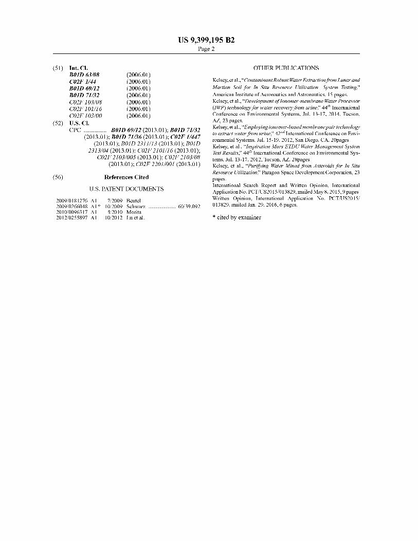
unit for holding and treating wastewater for water recovery.FIG. 2B shows a side view of the containment unit in FIG.
2A for holding and treating wastewater for water recovery.FIG. 3 shows a schematic of various layers in an example
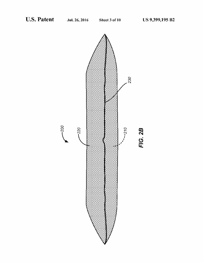
containment unit configured to hold and treat wastewater forwater recovery.FIG. 4A shows an example water processing apparatus
including a rigid housing structure supporting containmentunits configured to hold and treat wastewater for water recov-ery.
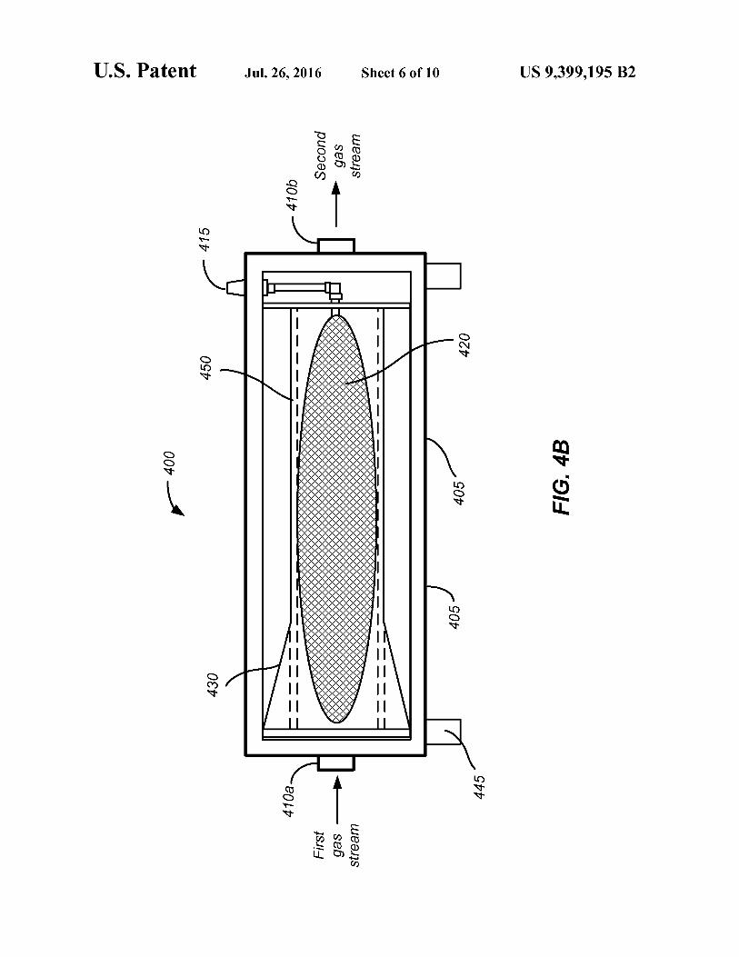
FIG. 4B shows a schematic of the example water process-ing apparatus of FIG. 4A including a rigid housing structuresupporting a containment unit configured to hold and treatwastewater for water recovery.FIG. 5 shows another example water processing apparatus
including a flexible housing structure supporting a contain-ment unit configured to hold and treat wastewater for waterrecovery.
FIG. 6A shows an example schematic diagram illustratinga water processing apparatus for treating wastewater.
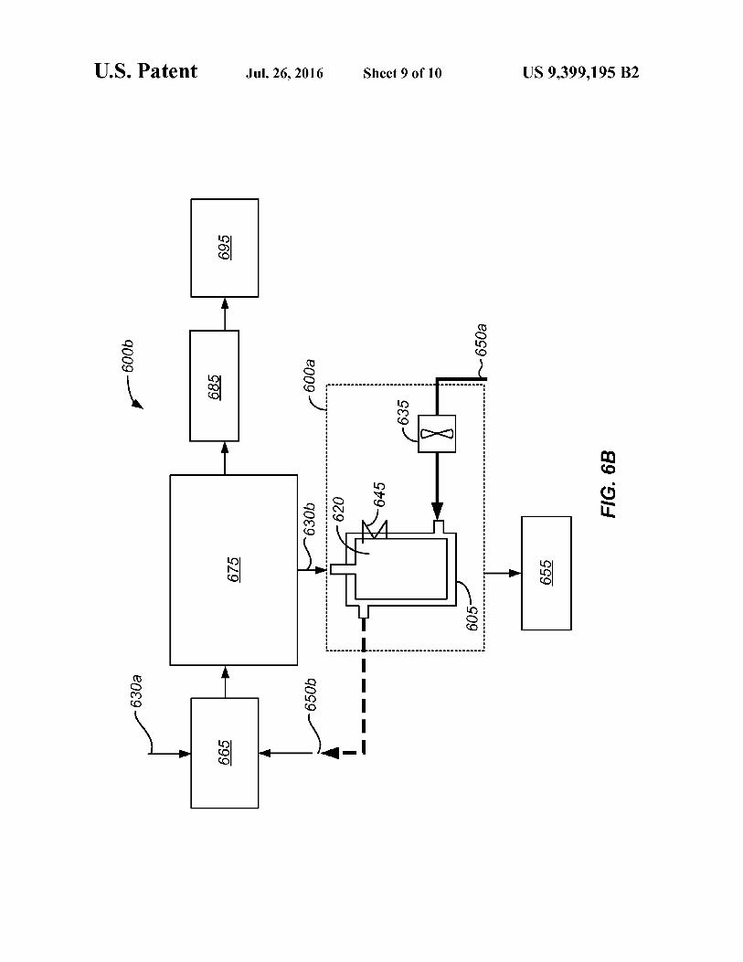
FIG. 6B shows an example schematic diagram illustratingthe water processing apparatus of FIG. 6A integrated in awater recovery system.FIG. 7 shows a schematic diagram illustrating a water
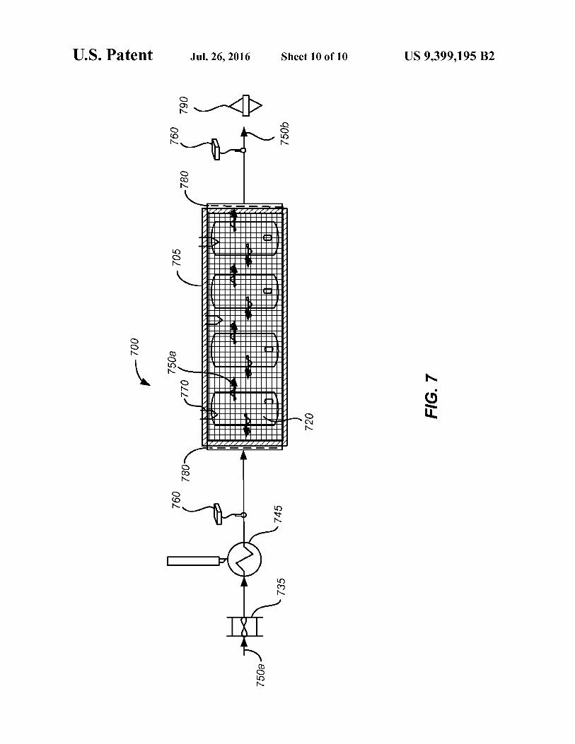
recovery system having containment units configured to holdand treat wastewater.
Like reference numbers and designations in the variousdrawings indicate like elements.
DETAILED DESCRIPTION
To reclaim water from wastewater, a water processingapparatus can be provided that can extract purified water in asingle step. The extracted water can meet water quality stan-dards, such as having a limited amount of total organic car-bon, total inorganic carbon, total dissolved solids, ammo-nium, urea, methanol, ethanol, propylene glycol, acetate,sulfate, formate, and other contaminants. The amount ofextracted water from the wastewater can also be significant.For example, the water processing apparatus can be capable
4of extracting over 75% of the water from the wastewater. Forexample, the water processing apparatus may be capable ofextracting equal to or greater than about 85% of the waterfrom brine, and extracting equal to or greater than about 98%
5 of the water from urine. The water processing apparatus canbe capable of using limited power and limit the use of con-sumable components.
Wastewater can come from a variety of sources, includingbut not limited to humidity condensate from air conditioning
io systems, hygiene water, seawater, polluted water, greywater,brine, and urine. Human urine can include several differentinorganic salts, urea, organic ammonium salts, and otherorganic compounds. Human urine also includes water, thepercentage of which can vary from person to person. Typical
15 samples of urine can be augmented to match that of a typicalcrew member of the ISS, where the percentage of non-watercompounds can be less than 20% and the percentage of watercan be greater than 80% in terms of mass fraction of the urine.For example, pretreated, augmented urine can include 6.06%
20 of non-water compounds and 93.94% of water, where theurine can be pretreated with sulfuric acid and chromiumtrioxide to prevent bacterial and mold growth and trap ammo-nium in solution as non-volatile ammonium ions. In someimplementations, water recovery techniques may be utilized
25 to purify water from urine. In some other implementations,water recovery techniques may be utilized to purify waterfrom brine. For example, the brine can be a form of concen-trated urine, where pretreated urine can be processed in aprimary water processor to become brine. Then the brine can
3o be further processed by the water processing apparatus of thepresent disclosure. The effectiveness of the present disclosurecan be evaluated in terms of the amount of water recoveryfrom the wastewater and the product water purity.The present disclosure provides for wastewater processing
35 using membrane technology. FIG. 1 shows a schematic dia-gram illustrating an example water processing apparatusincluding an ionomer and hydrophobic microporous mem-brane pair for extracting water from wastewater. A waterprocessing apparatus 5 for extracting water from wastewater
40 30 can include a first layer 10 over a second layer 20. The firstlayer 10 can include a hydrophobic microporous membraneand the second layer 20 can include an ionomer membrane.The first layer 10 and the second layer 20 can form an iono-mer-microporous membrane pair that can be used in water
45 recovery processes for a variety of applications, includingspace and terrestrial applications. The first layer 10 can beimpermeable to liquids and solids of the wastewater 30 butpermeable to gases and vapors 40 of the wastewater 30. Thesecond layer 20 can be permeable to water vapor 40b but
50 impermeable to one or more contaminants 40a of the gasesand vapors 40.In some implementations, the hydrophobic microporous
membrane of the first layer 10 can include polytetrafluoroet-hylene (PTFE) or, more specifically, expanded PTFE
55 (ePTFE). PTFE, sometimes referred to as "Teflon," can serveas a hydrophobic microporous membrane that prevents liquidwastewater 3 0 from coming into contact with the second layer20. The PTFE in the first layer 10 may prevent liquid waste-water 30 from passing but may permit gases and vapors 40 to
60 pass through. PTFE is hydrophobic and does not allow anyliquid to pass through its pores without significant backpres-sure. In addition, PTFE has high temperature limits and willgenerally not degrade at temperatures below about 250° C.PTFE is also very chemically inert and highly resistant to
65 corrosion. In some implementations, PTFE is able to handleheated, highly concentrated brine without any chemical cor-rosion or with minimal chemical corrosion. In some imple-
US 9,399,195 B25
mentations, the PTFE can be derived from Teflon manufac-tured by General Electric of Fairfield, Conn. An example ofPTFE can be derived from fabric of the product name eVent(k,which can be manufactured by the BHA Group, a subsidiaryof General Electric. The eVent(k product is commercially 5
available in different porosities and thicknesses, which canaffect permeation rates.
In some implementations, the ionomer membrane of thesecond layer 20 can include a sulfonated perfluorinated iono-mer, such as Nafion®. The ionomer membrane of the second iolayer 20 serves as a chemically-selective membrane thatallow compounds that bind to the sulfonic acid groups toreadily permeate through the second layer 20, includingwater. The ionomer membrane is a chemically-sensitivemembrane in that it selectively passes water through the iono- 15mer membrane based on chemical affinity. Rather than selec-tively removing water or other gases based on molecular size,the ionomer membrane can remove water and other gasesbased on chemical affinity. For example, the ionomer mem-brane can remove water and other gases based on their chemi- 20cal affinity for sulfonic acid groups.
Nafion® is a copolymer of tetrafluoroethylene and per-fluro-3,6-dioxa-4-methyl-7-octene-sulfonic acid. It is aninert fluorocarbon polymer with ionic channels of sulfonicacid groups scattered throughout. Nafion® is highly resistant 25to chemical attack, as only alkali metals such as sodium areknown to degrade Nafion® under normal temperatures andpressures. In fact, strong acids may be used to regenerateNafion® if it has been exposed to solutions containing cat-ions. Because of its inertness, Nafion® can be safely disposed 30in landfills. Nafion® does not burn in ambient air and is moreflame-resistant than most other plastics, with a limiting oxy-gen index of 95%. Nafion® sheets are commercially availablethrough Ion Power, Inc., which is a distributor of Nafion®under E. I. du Pont de Nemours and Company of Wilmington, 35Del. Different thicknesses of Nafion® are commerciallyavailable, which can affect the permeation rates.
Nafion® includes a bulk fluorocarbon matrix with exposedsulfonic acid groups immobilized in the bulk fluorocarbonmatrix. Unlike the fluorocarbon matrix, the sulfonic acid 40groups do not participate in chemical reactions. As a result,the sulfonic acid groups provide several important propertiesto Nafion®. First, Nafion® functions as an acid catalyst dueto the strongly acidic properties of the sulfonic acid group.Second, Nafion® functions as an ion exchange resin when 45exposed to liquid solutions. Third, Nafion® can readilyabsorb water, from the vapor phase or the liquid phase. Eachof the sulfonic acid groups can absorb up to 13 molecules ofwater. The sulfonic acid groups can form ionic channelsthrough the fluorocarbon polymer, and water can be easily 50transported through these channels. Thus, Nafion® can serveas a selective, semi-permeable membrane to water vapor. Insome implementations, the Nafion® of the second layer 20can be provided as a sheet or sheets. In some implementa-tions, the Nafion® can be solution-casted onto the first layer 5510. In some implementations, the Nafion® of the second layer20 can be provided as tubes that can form Nafion® tube walls.Nafion® tubes may be commercially available throughPerna Pure LLC of Toms River, N.J.
Nafion® can serve as a selective, semi-permeable mem- 60brane to water vapor for water purification because the sul-fonic acid groups can pass water while rejecting other com-pounds, making it possible to separate water from acontaminated source. The fact that Nafion® acts as an ionexchange resin when exposed to liquids implies that Nafion® 65is more effective processing gases rather than liquid solu-tions. Liquid solutions containing cations can reduce the
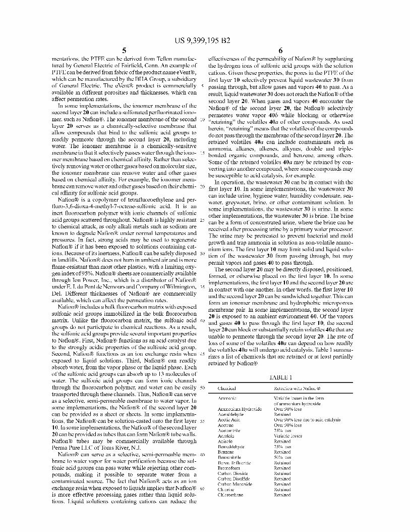
6effectiveness of the permeability of Nafion® by supplantingthe hydrogen ions of sulfonic acid groups with the solutioncations. Given these properties, the pores in the PTFE of thefirst layer 10 selectively prevent liquid wastewater 30 frompassing through, but allow gases and vapors 40 to pass. As aresult, liquid wastewater 30 does not reach the Nafion® of thesecond layer 20. When gases and vapors 40 encounter theNafion® of the second layer 20, the Nafion® selectivelypermeates water vapor 40b while blocking or otherwise"retaining" the volatiles 40a of other compounds. As usedherein, "retaining" means that the volatiles of the compoundsdo not pass through the membrane of the second layer 20. Theretained volatiles 40a can include contaminants such asammonia, alkanes, alkenes, alkynes, double and triple-bonded organic compounds, and benzene, among others.Some of the retained volatiles 40a may be retained by con-verting into another compound, where some compounds maybe susceptible to acid catalysis, for example.In operation, the wastewater 30 can be in contact with the
first layer 10. In some implementations, the wastewater 30can include urine, hygiene water, humidity condensate, sea-water, greywater, brine, or other contaminant solution. Insome implementations, the wastewater 30 is urine. In someother implementations, the wastewater 30 is brine. The brinecan be a form of concentrated urine, where the brine can bereceived after processing urine by a primary water processor.The urine may be pretreated to prevent bacterial and moldgrowth and trap ammonia in solution as non-volatile ammo-nium ions. The first layer 10 may limit solid and liquid solu-tion of the wastewater 30 from passing through, but maypermit vapors and gases 40 to pass through.The second layer 20 may be directly disposed, positioned,
formed, or otherwise placed on the first layer 10. In someimplementations, the first layer 10 and the second layer 20 arein contact with one another. In other words, the first layer 10and the second layer 20 can be sandwiched together. This canform an ionomer membrane and hydrophobic microporousmembrane pair. In some implementations, the second layer20 is exposed to an ambient environment 60. Of the vaporsand gases 40 to pass through the first layer 10, the secondlayer 20 can block or substantially retain volatiles 40a that areunable to permeate through the second layer 20. The rate ofloss of some of the volatiles 40a can depend on how readilythe volatiles 40a will undergo acid catalysis. Table 1 summa-rizes a list of chemicals that are retained or at least partiallyretained by Nafion®.
IK0.3mmi
Chemical Retention with Nation
Ammonia variable losses in the formof ammonium hydroxide
Ammonium Hydroxide Over 90% lossAcetaldehyde RetainedAcetic Acid Over 90% loss due to acid catalysisAcetone Over 90% lossAcetonitrile 75% lossAcrolein variable lossesAnisole RetainedBenzaldehyde 75% lossBenzene RetainedBenzonitrile 50% lossBoron Trifluoride RetainedBromoform RetainedCarbon Dioxide RetainedCarbon Disulfide RetainedCarbon Monoxide RetainedChlorine RetainedChloroethane Retained

US 9,399,195 B27
TABLE 1-continued
Chemical Retention with Nation
Chloroform RetainedCrotonaldehyde Over 90% lossCumene RetainedDiacetyl Over 90% lossDiethyl Carbitol variable lossesDimethylformanide Over 90% lossDimethylacetamide Over 90% lossDioxane Over 90% lossDMS RetainedDMSO Over 90% lossEthane RetainedEthanol Over 90% lossEthyl Acetate 15% lossEthyl Amyl Ketone 20% lossEthyl Benzene RetainedEthyl Ether Over 90% lossEthylene RetainedEthylene Oxide 50% lossFluorine RetainedFluorobenzene RetainedFormaldehyde RetainedFormic Acid variable lossHelium RetainedHeptane RetainedHexane RetainedHydrogen RetainedHydrogen Chloride Retained with high purgeHydrogen Cyanide RetainedHydrogen Fluoride RetainedHydrogen Sulfide RetainedIsopropyl Benzene RetainedIsobutyl Acetate Over 90% lossIsovaleric Acid variable lossesMEK Over 90% lossMesitylene RetainedMethane RetainedMethanol Over 90% lossMethyl Acetate RetainedMethyl Bromide RetainedMethyl Chloride RetainedMethyl Isobutyl Ketone Over 90% lossMethyl Methacylate RetainedMethyl Nitrate variable lossesMethyl Sulfide RetainedNitrobenzene 30% lossNitrogen RetainedNitrogen Dioxide RetainedOctane RetainedOxygen RetainedOzone RetainedPropane RetainedPhosgene RetainedPropionicAcid variable lossesPropylene RetainedPropylene Oxide 25% lossPyridine RetainedSulfur Dioxide RetainedTetrahydrofuran Over 90% lossThiosinamine Over 90% lossToulene RetainedTrichloroethene RetainedWater Over 90% lossXylene Retained
The Nafion® of the second layer 20 may block or substan-tially retain volatiles 40a that come from the wastewater 30.The Nafion® of the second layer may allow other vapors andgases 40 to pass, including water vapor 40b. Of note, alco-hols, ammonium hydroxide, primary amines, and secondaryamines may selectively permeate through the Nafion® of thesecond layer 20, driven by their vapor pressure gradients.Even though some volatiles 40a may pass through both mem-branes, the contamination of the permeated water vapor 40bmay be minimal based on total organic carbon (TOC), ammo-nia, ammonium, and pH measurements.
8The water vapor 40b can pass through the second layer 20
by being driven by a partial pressure differential. In someimplementations, the water vapor partial pressure in theambient environment 60 is less than the water vapor partial
5 pressure inside the second layer 20. Water molecules of thewater vapor 40b can bind to the sulfonic acid groups of theNafion® in the second layer 20, and then pass through by thepartial pressure differential. Rapid transfer through the sec-ond layer 20 can keep the partial pressure between the first
io layer 10 and the second layer 20 low, allowing for highdiffusion through the first layer 10.The water vapor partial pressure differential is the driving
force for permeation of water vapor 40b. The larger the dif-ferential, the higher the potential for permeation. The water
15 vapor partial pressure differential can be maintained by a drysweep gas flowing over the second layer 20. As illustrated inthe example in FIG. 1, a purge gas 50 can flow through theambient environment 60 to sweep the water vapor 40b. Thepurge gas 50 can flow across the surface of the second layer 20
20 to pick up the water vapor 40b and transport the water vapor40b. In some implementations, the water vapor 40b can betransported to a condenser (not shown). In some implemen-tations, the purge gas 50 can include air, such as room airdelivered by a fan or compressor. However, it is understood
25 that the purge gas 50 can include any gas that has as watervapor partial pressure that is lower than the water vaporpartial pressure inside the second layer 20. For example, thepurge gas 50 can include one or more of nitrogen (Nz), carbondioxide (CO2), hydrogen (Hz), and inert gas.
30 The flow rate, temperature, and relative humidity of thepurge gas 50 can be adjusted to increase the permeation of thewater vapor 40b from the wastewater 30 to the ambient envi-ronment 60. For example, increasing the flow rate of the purgegas 50 can increase the permeation of the water vapor 40b and
35 prevent saturation. Increasing the temperature can increasethe permeation of the water vapor 40b to counteract theeffects of evaporative cooling. Decreasing the relative humid-ity of the purge gas 50 can increase the permeation rate ofwater vapor 40b.
40 The permeation of water vapor 40b may also be affectedbyother factors. In some implementations, the level of hydrationof the Nafion®, the phase of water on the side of the waste-water 30, interfacial transport, surface area ratio of the firstlayer 10 to the second layer 20, membrane thicknesses, and
45 porosity of the PTFE membrane can affect the permeation ofwater vapor 40b.
With respect to surface area ratio of the first layer 10 to thesecond layer 20, high permeation rates can be achieved whenthe first layer 10 has a similar surface area as the second layer
5o 20. For example, comparative permeation rates throughPTFE and Nafion® reveal relatively similar permeation rates.Thus, neither the PTFE nor the Nafion® membranes requiresubstantially greater surface areas than the other to get thepermeation rates to be the same. Hence, the first layer 10 can
55 have a first surface area and the second layer 20 can have asecond surface area, where the ratio of the first surface area tothe second surface area can be between about 1.25:1 andabout 1:1.25, or about 1:1.
Regarding the thicknesses of the membranes, thicker mem-6o brans generally mean more diffusion resistance. Regarding
the porosity of the PTFE membrane, larger pores typicallyprovide greater permeation rates. Selective membrane testingrevealed that while the membrane combination having thehighest permeation rate was the combination of the PTFE
65 membrane having an average pore size of I µm and theNafion® membrane having a thickness of 25.4 µm, the com-bination was structurally unstable during handling. However,

US 9,399,195 B2I
the membrane combination having a higher permeation ratethan the rest of the membrane combinations was the combi-nation of the PTFE membrane having an average porosity of0.45 µm and the Nafion® membrane having a thickness of50.8 µm, even if the pore size were higher or the Nafion®thickness was smaller. In some implementations, the perme-ation flux rate of water vapor can be greater than 8.0x10⁻⁵
kg/s*m2, or greater than 1.0x10⁻⁴ kg/s*m2.As the water vapor 40b permeates from the Nafion® of the
second layer 20, the retained wastewater 30 can turn intoresidual brine solids or sludge. If the mass fraction of thewastewater is over 80% water and if most of the water ispermeated through the second layer 20 of the water process-ing apparatus 5, then what remains of the wastewater 30 willbe mostly solid. The solid can be safely stored to facilitateease of handling and disposal.The water processing apparatus 5 described in FIG.1 may
be part of a containment unit for holding and treating waste-water 30. In some implementations, such a containment unitcan be a bag or inflatable bladder sealed from the ambientenvironment 60. FIG. 2A show a top plan view of an examplecontainment unit for holding and treating wastewater forwater recovery. FIG. 2B shows a side view of the containmentunit in FIG. 2A. The containment unit 200 can include anionomer membrane 220 and a hydrophobic microporousmembrane 210. The ionomer membrane 220 can be a sheetthat is exposed to the ambient environment outside of thecontainment unit 200, and the hydrophobic microporousmembrane 210 can be a sheet that forms the interior of thecontainment unit 200. The sheet of the hydrophobicmicroporous membrane 210 can be folded over itself and thesheet of the ionomer membrane 220 can be sealed to thehydrophobic microporous membrane 210 to form a four-sided envelope. A seal 230 can be formed around the edges ofthe containment unit 200 to enclose the containment unit 200.In some implementations, the containment unit 200 can besealed using an adhesive, heat sealing, or a mechanical sealsuch as a clamp. The interior of the containment unit 200 maybe in contact with wastewater, such as urine or brine. In someimplementations, the containment unit 200 may include areceptacle 225 for receiving the wastewater. As shown in FIG.213, the containment unit 200 may be inflated and hold thewastewater.
In the containment unit 200, the surface areas of the hydro-phobic microporous membrane 210 and the ionomer mem-brane 220 can be relatively similar. The sheet of the ionomermembrane 220 can overlay and surround the sheet of thehydrophobic microporous membrane 210. In some imple-mentations, a surface area ratio of the hydrophobicmicroporous membrane 210 to the ionomer membrane 220can be between about 1.25:1 and 1:1.25. In some implemen-tations, the surface area ratio can be approximately 1:1. Byhaving relatively similar surface areas, a permeation rate ofthe water vapor through the containment unit 200 can beoptimized.The dual membranes of the containment unit 200 form two
chemically resistant layers that provide at least two layers ofprotection. Additional layers or membranes can be added forincreased protection. The containment unit 200 is durable,portable, and effectively encloses the wastewater inside thecontainment unit 200. In some implementations, this allowsfor ease of handling and disposal by crew members. That way,the solids and remaining wastewater in the containment unit200 can be safely handled and disposed of without furtherprocessing because the containment unit 200 serves as aself-containing storage.
10FIG. 3 shows a schematic of various layers in an example
containment unit configured to hold and treat wastewater forwater recovery. FIG. 3 represents a cross-sectional schematicshowing the arrangement of layers 310, 320, 330, and 340
5 withrespect to one another in the containment unit 300. A firstlayer 310 can include a hydrophobic microporous membraneand can be folded on itself to form the interior of the contain-ment unit 300. In some implementations, the hydrophobicmicroporous membrane canbe PTFE. A second layer 320 can
io include an ionomer membrane and can be disposed, posi-tioned, formed, or otherwise placed on the first layer 310.Thus, the second layer 320 can surround the first layer 310 onall sides of the containment unit 300. In some implementa-tions, the ionomer membrane can be a sulfonated perfluori-
15 nated ionomer, such as Nafion®. The second layer 320 canbeexposed to the ambient environment.In order to seal the containment unit 300, a sealing material
330 can be provided in the interior of the containment unit300. The sealing material 330 can be provided on the first
20 layer 310 so that the first layer 310 canbe sealed to itself. Thesealing material 330 can be chemically resistant to concen-trated brine in the wastewater to prevent leakage of the con-tainment unit 300. In some implementations, the sealingmaterial 330 includes a thermoplastic, such as polypropylene.
25 The polypropylene can be melted and seep into the pores ofthe first layer 310 so that the first layer 310 can be sealed to thesecond layer 320 as well. Thus, a weld can be formed insealing the first layer 310 to itself and between the first layer310 and the second layer 320. The weld can be formed along
30 the edges of the containment unit 300. This can be shown inthe seal 230 in FIGS. 2A and 2B. In some other implementa-tions, the sealing material 330 can be an adhesive.An outer layer 340 can be provided on the second layer 320
to provide structural support and reinforcement. The outer35 layer 340 can form the exterior of the containment unit 300,
while allowing the second layer 320 to still be exposed to theambient environment. In some implementations, the outerlayer 340 can include a thermoplastic, such as polyethylene.The polyethylene can strengthen the containment unit 300 so
40 that it is less likely to tear. More specifically, the polyethyleneon each side can support the layers 310, 320 to preventstretching when it is pressurized by fluid weight or pressurefor ease of handling. The outer layer 340 can provide a thirdlayer of protection on top of the first layer 310 and the second
45 layer 320. In some implementations, the outer layer 340 canbe provided as netting or mesh surrounding the second layer320 on all sides of the containment unit 300.From the inside to the outside, one side of the containment
unit 300 includes a sealing material 330 such as smooth50 polypropylene netting, a first layer 310 such as PTFE, a
second layer 320 such as Nafion®, and an outer layer 340such as polyethylene netting. The other side of the contain-ment unit 300 can be symmetrical with respect to the order ofthe layers 330, 310, 320, and 340. In some implementations,
55 heat sealing orwelding can seal all ofthelayers 330, 310, 320,and 340 together around the edges to enclose the containmentunit 300. In some other implementations, an adhesive or amechanical seal can seal all of the layers 330, 310, 320, and340 together to enclose the containment unit 300.
60 One or more containment units may be positioned in anapparatus for extracting water into a gas stream. For example,the one or more containment units can be supported in ahousing structure, where the housing structure provides a dryenvironment for maintaining a water vapor partial pressure
65 differential. A gas stream can flow over the one or morecontainment units. In some implementations, the housingstructure can include materials that are liquid and gas imper-

US 9,399,195 B211
meable, and also have a high chemical resistance. Someimplementations of the housing structure can be made of rigidmaterials and some other implementations of the housingstructure can be made of soft or flexible materials.FIG. 4A shows an example water processing apparatus
including a rigid housing structure supporting containmentunits configured to hold and treat wastewater for water recov-ery. FIG. 4B shows a schematic of the water processing appa-ratus of FIG. 4A. The water processing apparatus 400includes a containment chamber or housing structure 405,where a first end of the housing structure 405 includes a gasinlet 410a and a second end of the housing structure 405includes a gas outlet 410b. The gas inlet 410a may be con-figured to receive a first gas stream into the housing structure405, and a gas outlet 410b may be configured to deliver asecond gas stream out of the housing structure 405. Thesecond gas stream includes water. In some implementations,the relative humidity of the second gas stream exiting thehousing structure 405 is greater than the first gas streamentering the housing structure 405.The water processing apparatus 400 further includes one or
more containment units 420 for holding and treating waste-water for water recovery. In some implementations, the one ormore containment units 420 can be a bag or inflatable bladder.The one or more containment units 420 can include an iono-mer membrane, such as Nafion®, and a hydrophobicmicroporous membrane, such as ePTFE. The ionomer mem-brane can overlay and surround the hydrophobic microporousmembrane to form a membrane pair. The one or more con-tainment units 420 maybe supported inside the housing struc-ture 405. In some implementations, the one or more contain-ment units 420 may be placed on a cage, platform, or othersupport structure 450 inside the housing structure 405. Thecage, platform, or other support structure 450 may be remov-able for ease of handling.The housing structure 405 may include feedthroughs for
the first and second gas streams, connections for wastewaterflow, instrumentation (e.g., sensors, thermocouples, etc.), andone or more doors to insert/remove the one or more contain-ment units 420. As illustrated in FIG. 413, the one or morecontainment units 420 maybe fluidly coupled to a wastewaterinlet 415 for receiving wastewater from a wastewater supply(not shown). In some implementations, the wastewater (e.g.,urine or brine) can flow from the wastewater supply and intothe one or more containment units 420 via the wastewaterinlet 415. For example, a pump or compressor can meterbrineinto the containment units 420 from a brine storage tank.
In addition, the housing structure 405 may include instru-mentation such as thermocouples for temperature control andmonitoring. At least one of the thermocouples may be posi-tioned on the one or more containment units 420 and used forfeedback control for maintaining the one or more contain-ment units 420 at a desired temperature. In some implemen-tations, the one or more containment units 420 are maintainedat a temperature above room temperature to overcome effectsof evaporative cooling. Additional thermocouples may bepositioned in the housing structure 405 to monitor the tem-perature of the housing structure 405 and other components.
In some implementations, the housing structure 405 mayinclude one or more doors 440 for inserting and removing theone or more containment units 420. In some implementa-tions, the one or more doors 440 can be made of polymeth-ylpentene (PMP), which is a thermoplastic that is semi-trans-parent and chemically resistant to a variety of compounds. Afluoroelastomer (FKM) may be used as the sealing mecha-nism for the one or more doors 440. In some implementations,the housing structure 405 may include feet or support com-
12ponents 445. The support components 445 may provide clear-ance for hinges and for the one or more doors 440 to easilyopen. In some implementations, at least some portions of thehousing structure 405 may be transparent or semi-transparent
5 to allow for visibility for monitoring the one or more contain-ment units 420. In some implementations, the housing struc-ture 405 can be made of a weldable thermoplastic, such aspolyvinylidene (PVDF), which can be referred to as Kynar.PVDF exhibits excellent chemical resistance to a variety of
io compounds, including chromic, sulfuric, and phosphoricacid.
Other parts of the housing structure 405 may be made outof polypropylene, PVDF, PTFE sealant, and hydrophobicPTFE filters. The hydrophobic PTFE filters may be posi-
15 tioned in the housing structure 405 to provide containment incase of a brine leak and also to provide pressure drop foradequate flow distribution. Joints in the housing structure 405may be sealed using PTFE to limit leakage of wastewater. It isunderstood that those of ordinary skill in the art may design
20 the housing structure 405 using other materials or configura-tions considering issues such as design preference, cost, per-formance requirements, system requirements, safetyrequire-ments, available materials, technological advances, etc.A first gas stream may flow into the housing structure 405
25 through the gas inlet 410a, where the first gas stream mayflow over the surfaces of each of the containment units 420. Insome implementations, the first gas stream can include air,such as room or cabin air. The first gas stream can helpmaintain a water vapor partial pressure differential in the
so housing structure 405. When the first gas stream entersthrough the gas inlet 410a, a flap 430 may divert flow of thefirst gas stream gas into the housing structure 405 to maintainconstant flow channels while the containment units 420deflate during drying. The flap 430 may include ePTFE and
35 maybe locatedatthe top of the support structure 450. The flap430 may divert the first gas stream to a channel just above thesurface of the one or more containment units 420, maintain-ing velocity for mass transfer as the height of the one or morecontainment units 420 decreases.
40 After the first gas stream sweeps across the containmentunits 420, the first gas stream captures water vapor and isflowed towards the gas outlet 410b. After collecting the watervapor from the containment units 420, the first gas streambecomes a second gas stream upon exiting the gas outlet
45 410b. The second gas stream includes water, where the rela-tive humidity of the second gas stream is greater than therelative humidity of the first gas stream. The second gasstream can be delivered to a condenser for collecting thewater.
50 FIG. 5 shows another example water processing apparatusincluding a flexible housing structure supporting a contain-ment unit configured to hold and treat wastewater for waterrecovery. In FIG. 5, the water processing apparatus 500includes a containment unit 520, where the containment unit
55 520 can be a bag or inflatable bladder in some implementa-tions. The containment unit 520 can include an ionomermembrane and a hydrophobic microporous membrane. Theionomer membrane can overlay and surround the hydropho-bic microporous membrane to form a membrane pair. A hous-
60 ing structure 505 can surround the containment unit 520 toenclose the containment unit 520, where the housing structure505 can be made of a flexible material. The flexible materialcan liquid and gas impermeable. For example, the flexiblematerial can include polypropylene or another chemically
65 resistant plastic.The housing structure 505 can include a gas inlet 510a and
a gas outlet 510b opposite the gas inlet 510a. The gas inlet
US 9,399,195 B213
510a may be configured to receive a first gas stream into thehousing structure 505, and the gas outlet 510b may be con-figured to deliver a second gas stream out of the housingstructure 505. The second gas stream includes water. In someimplementations, the relative humidity of the second gasstream exiting the housing structure 505 is greater than thefirst gas stream entering the housing structure 505.
Integrated springs or support structure 530 may providesupport to a flexible sheet of the housing structure 505. Ratherthan a rigid enclosure, the flexible sheet 505 can wrap aroundthe support structure 530 to form the housing structure 505.The support structure 530 may provide sufficient compres-sive force to maintain the desired flow geometry and spacingbetween the flexible sheet of the housing structure 505 and thecontainment unit 520. The gas inlet 510a and the gas outlet510b may direct and control flow of the first gas stream acrossthe surface of the containment unit 520, where the first gasstream can flow between the containment unit 520 and theflexible sheet of the housing structure 505. The first gasstream can be a dry purge gas. In some implementations, asthe containment unit 520 deflates, the housing structure 505can also deflate.
After the first gas stream sweeps across the containmentunit 520, the first gas stream captures water vapor and isflowed towards the gas outlet 510b. After collecting the watervapor from the containment unit 520, the first gas streambecomes a second gas stream upon exiting the gas outlet510b. The second gas stream includes water, where the rela-tive humidity of the second gas stream is greater than therelative humidity of the first gas stream. The second gasstream can be delivered to a condenser for collecting thewater.
With respect to FIGS. 4A, 413, and 5, the water processingapparatuses 400, 500 can be configured to provide conditionsinside the housing structures 405, 505 to promote permeationof water vapor from the one or more containment units 420,520. For example, the water processing apparatuses 400, 500can regulate the flow of purge gas, temperature, pressure,relative humidity, and other conditions within the housingstructures 405, 505. Any of the water processing apparatuses400, 500 can include a controller (not shown) containinginstructions for controlling processing conditions in the hous-ing structures 405, 505.The air of the first gas stream can be pre-heated to over-
come the effects of evaporative cooling, and the air can berelatively dry to maintain a water vapor partial pressure dif-ferential between the containment units 420, 520 and theambient environment. In some implementations, the air canbe pre-heated above room temperature to increase the vaporpressure inside each of the containment units 420, 520, whereroom temperature can be between about 18° C. and about 30°C. For example, the temperature of the first gas stream can beheated to be greater than about 30° C. The increased tempera-ture increases the vapor pressure to generate more vapors andgases from the wastewater in each of the containment units420, 520. In addition, the first gas stream can be relatively dry.Typically, cabin air has a relative humidity between about35% and about 45%. The water processing apparatuses 400,500 can also maintain a water vapor partial pressure differ-ential to promote permeation of water vapor inside the hous-ing structures 405, 505. In other words, the water vapor partialpressure inside each of the containment units 420, 520 isgreater than the water vapor partial pressure in the housingstructures 405, 505. As the first gas stream flows across thesurface of each of the containment units 420, 520, the first gasstream can transport water vapor away from the containmentunits 420, 520. Increasing the flow rate of the first gas stream
14can provide a continuously dry environment inside the hous-ing structures 405, 505. The flow rate of the first gas streamcan be adjusted depending on the surface area, performancerequirements, etc. of the containment units 420, 520. By way
5 of an example, the flow rate of the first gas stream can bebetween about 300 standard liters per minute (SLPM) andabout 700 SLPM, such as about 500 SLPM, where the surfacearea of the containment unit 420, 520 is about 750 squareinches and the desired water recovery from urine is about
10 98%.In some implementations, the gas inlet 410a or 510a and
the gas outlet 410b or 510b can passively control air flowacross the containment unit 520. In particular, the housingstructures 405, 505 may permit the flow of the first gas stream
15 without any blower or heater, thereby reducing power con-sumption in the water processing apparatuses 400, 500. Forexample, the first gas stream may originate from sourceswithin a larger apparatus, such as from an air duct in a space-craft.
20 FIG. 6A shows an example schematic diagram illustratinga water processing apparatus for treating wastewater. Thewater processing apparatus 600a can include a housing struc-ture 605 for containing a containment unit 620. The housingstructure 605 can be similar to any of the housing structures
25 described with respect to FIGS. 4A, 413, and 5. The contain-ment unit 620 can include a membrane pair of an ionomermembrane and a hydrophobic microporous membrane, asdescribed earlier with respect to FIGS. 1-3. The containmentunit 620 can be configured to hold wastewater, such as urine
30 or brine.A first gas stream 650a can be introduced into the housing
structure 605. In some implementations, the first gas stream650a can include cabin air originating from one or moresystems of a spacecraft. The first gas stream 650a can be
35 delivered into the housing structure 605 by a fan or blower635, where the blower 635 can control the flow rate of the firstgas stream 650a into the housing structure 605. In someimplementations, the blower 635 can be equipped with amotor with a variable frequency drive to control fan speed.
4o However, in some implementations, the water processingapparatus 600a can introduce the first gas stream 650a pas-sively, and thereby introduce the first gas stream 650a withoutthe aid of the blower 635.In some implementations, the water processing apparatus
45 600a can include a heater 645. The heater can be utilized toheat the first gas stream 650a to above room temperature. Insome implementations, the first gas stream 650a can beheated to a temperature above 30° C., or to a temperatureabove 50° C. The heated first gas stream 650a can enter the
5o housing structure 605 to promote drying of the containmentunit 620. The heated first gas stream 650a can heat up thetemperature of the wastewater to overcome the effects ofevaporative cooling, where the temperature of the wastewatercan be above 30° C. However, in some implementations, the
55 water processing apparatus 600a does not heat up the waste-water and may introduce the first gas stream 650a passively,and thereby introduce the first gas stream 650a without the aidof the heater 645.The first gas stream 650a can transport captured water
60 vapor permeating from the containment unit 620 to become asecond gas stream 650b. The second gas stream 650b exits thehousing structure 605, where the second gas stream 650bincludes water. Overtime, the containment unit 620 becomesless inflated and relatively dry. In some implementations, the
65 water of the second gas stream 650b can enter the cabin of thespacecraft or flow directly towards a heat exchanger for col-lecting the water.
US 9,399,195 B215
FIG. 6B shows an example schematic diagram illustratingthe water processing apparatus of FIG. 6A integrated in awater recovery system. The water recovery system 600b canbe configured to treat wastewater and recover water. Thewater recovery system 600b can include the water processing 5
apparatus 600a, where wastewater can be provided into thecontainment unit 620 of the water processing apparatus 600afrom a primary water processor 675. The primary water pro-cessor 675 of the water recovery system 600b can receive afirst wastewater 630a from a wastewater storage 665, where iothe first wastewater 630a can include pretreated urine. Thefirst wastewater 630a can be processed by the primary waterprocessor 675 to convert the firstwastewater 630a to a secondwastewater 630b, where the second wastewater 630b can bebrine. In some implementations, the brine can be a form of 15concentrated urine.
After the first gas stream 650a flows over the containmentunit 620 and becomes the second gas stream 650b, the secondgas stream 650b exits the housing structure 605. In someimplementations, the second gas stream 650b can flow back 20into the cabin of the spacecraft or into a heat exchanger (e.g.,condenser) for extracting the water. As illustrated in FIG. 613,the second gas stream 650b can become humidity condensatethat can get further processed by the primary water processor675, and then undergo more processing in a post-processing 25unit 685. After po st-proces sing, the humidity condensate getscollected into potable water storage 695. The potable waterstorage 695 can be used by crewmembers of the spacecraft.The containment unit 620 can retain brine solids/sludge,
where the ionomer membrane and hydrophobic microporous 30membrane serve as a barrier between the brine solids/sludgeand crewmembers of the spacecraft. The containment unit620 contains the brine solids/sludge and prevents other vola-tiles from entering the ambient environment. The contain-ment unit 620 can be removed into storage into a solid waste 35storage unit 655. In some implementations, the containmentunit 620 can be disposed of without the need for furtherprocessing.
FIG. 7 shows a schematic diagram illustrating a waterrecovery system having containment units configured to hold 40and treat wastewater. The water recovery system 700 is con-figured to treat wastewater and recover water. The waterrecovery system 700 includes various devices, subsystems,components, sensors, and equipment for recovering waterfrom wastewater. The water recovery system 700 includes a 45containment chamber or housing structure 705 for supportinga plurality of containment units 720. The containment cham-ber 705 can be similar to either of the housing structure 405,505 described with respect to FIGS. 4A, 413, and 5. Each ofthe containment units 720 can include a membrane pair of an 50ionomer membrane and a hydrophobic microporous mem-brane, as described earlier with respect to FIGS. 1-3.A first gas stream 750a can include air that can be delivered
into the containment chamber 705 by a blower 735, where theblower 735 can control the flow rate of the first gas stream 55750a into the containment chamber 705. The water recoverysystem 700 can also include a heater 745 to heat the first gasstream 750a. The heater 745 can be positioned upstream ofthe containment chamber 705 and utilized to heat the first gasstream 750a above room temperature. In some implementa- 60tions, the water recovery system 700 can operate passively sothat the first gas stream 750a can be introduced into thecontainment chamber 705 without the aid of the blower 735or the heater 745.The water recovery systems 700 can also include instru- 65
mentation for monitoring or controlling conditions of thewater recovery system 700. For example, the water recovery
16system 700 can include sensors 760 for measuring relativehumidity entering and exiting the containment chamber 705.The relative humidity of the first gas stream 750a entering thecontainment chamber 705 can be less than the relative humid-ity of a second gas stream 750b exiting the containmentchamber 705. In some implementations, a desiccant can beused to dehumidify the first gas stream 750a prior to enteringthe containment chamber 705. Thermocouples 770 may belocated inside the containment chamber 705 to monitor thetemperature of the containment chamber 705 and the contain-ment units 720. At least one of the thermocouples 770 may beconnected to a controller for the heater 745 to maintain thewastewater temperature. Other sensors can be used in thewater recovery system 700 to measure relevant conditions ofthe gas streams 750a, 750b, such as pressure. The tempera-ture, pressure, and relative humidity of the first gas stream750a entering the containment chamber 705 can be comparedagainst the temperature, pressure, and relative humidity of thesecond gas stream 750b exiting the containment chamber705, which can be used for evaluating the permeation rate ofthe containment units 720. However, the water recovery sys-tem 700 can function without one or more of the aforemen-tioned instrumentation. In some implementations, the condi-tions of the water recovery system 700 can be monitoredvisually.In some implementations, the containment chamber 705
can include hydrophobic filters 780 at an inlet end and at anoutlet end of the containment chamber 705. The hydrophobicfilters 780 can include PTFE or some other chemically resis-tant material to provide secondary containment in the event ofa leak or rupture of any of the containment units 720.
Wastewater can be injected into the one or more of thecontainment units 720. In some implementations, the waste-water can be pretreated to inhibit microbial activity, minimizeprecipitation of solids, and limit volatilization of contami-nants such as ammonia. In some implementations, the waste-water can be pre-processed to convert pretreated urine intobrine. The containment units 720 are disposable and config-ured to be permeable to water vapor while retaining the liquidwastewater and other volatiles inside the containment units720. The water vapor permeation is driven by a partial pres-sure gradient across the permeable membrane material of thecontainment units 720. The partial pressure gradient can bemaintained by the flow of the first gas stream 750a. The firstgas stream 750a flows through the containment chamber 705to promote drying and sweeps permeated water vapor out ofthe containment chamber 705. The first gas stream 750a ishumidified to become a second gas stream 750b upon exitingthe containment chamber 705. The humidified second gasstream 750b is delivered to a condenser 790, where the watervapor condenses so that water can be collected and processedinto potable water. In some implementations, the condenser790 can include one or more countercurrent heat exchangers.The water in the second gas stream 750b can be condensed inthe condenser 790 for collection and processing into potablewater.In some implementations, the amount of water recovered
from the second gas stream 750b can be equal to or greaterthan about 95% of the water in the wastewater (e.g., urine).This can be true when the water processing system 700 func-tions as the primary water processor. However, when used asa brine processor, the amount of water recovered from thesecond gas stream 750b can be equal to or greater than about80% of the water in the wastewater (e.g., brine). Thus, in someimplementations, the water recovery is from pretreated urinebrine. In some other implementations, the water recovery isfrom urine wastewater. The percentage of water recovery can

US 9,399,195 B217
be calculated using the equation: % H2O recovered-(massH2O extracted)/(mass urine processed)x100, where the massH2O extracted can be calculated using by taking the finalmass of the containment units 720 and subtracting that fromthe starting mass of the containment units 720.The recovered water can be further processed and analyzed
for contaminants. For example, the recovered water can beanalyzed for water quality and purity, where measurementscan be taken for TOC, total dissolved solids (TDS), totalcoliform, and pH. For example, the recovered water can beanalyzed and tested for TOC, ammonium, and pH, where therecovered water from the humidified second gas stream canhave a TOC of equal to or less than about 100 mg/L, anammonium concentration of equal to or less than about 20ppm, and a pH between about 3 and 7. Other measurementscan be taken for conductivity, acetic acid, formic acid, totalinorganic carbon (TIC), and urea.
Using urine wastewater, water quality was tested afterrecovering water from a water recovery system as describedherein. Different tests 1-7 were performed using varyingchamber inlet temperatures, air flow, pressure drops, andoutlet pressures. The outputs of water quality and percentagewater recovery on tests 1-7 are displayed below in Table 2,where measurements of water quality were performed on theproduct condensate. However, water quality measurementswere not available for test 1. The tests showed that the per-centage water recovery was greater than 90% across all seventests, that ammonium and pH requirements were met on all ofthe available tests, and that TOC requirements were met onfour of the six available tests. This shows that significantcontaminant reduction can be achieved using a water recov-ery system as described herein.
TABLE 2
Total Percent TOC AmmoniumTest H2O Recovery (ppm) (ppm) pH
1 92%2 95% 149 3.48 6.53 95% 65.8 0.25 6.74 91% 70.8 0.611 6.65 92% 48.9 2.4 6.06 92% 47.4 2.94 6.87 96% 121 2.04 7.0
Using brine wastewater, water quality was tested afterrecovering water from a water recovery system as describedherein. Different tests 1-2 were performed using varying tem-peratures, flow rates, and pressure. The different operatingconditions led to different amounts of waterrecovery from thesamples of brine. The outputs of water quality and percentagewater recovery on tests 1-2 are displayed in Table 3, wheremeasurements of water quality were performed on the prod-uct condensate. The tests showed that the percentage of waterrecovery was greater than 80% from brine, meaning that thetotal water recovery from urine was greater than 95%. Thetests also showed that significant contaminant reduction canbe achieved from brine using a water recovery system asdescribed herein.
TABLE 3
Total Percent TOC AmmoniumTest H2O Recovery (ppm) (ppm) pH
1 82% 90.3 2.4 3.9(97% from urine) (after 4 days) (after 4 days) (after 4 days)
2 86% 136 8.0 4.1(98% from urine) (after 9 days) (after 9 days) (after 9 days)
18In some implementations, a water processing apparatus as
described in the present disclosure using membrane technol-ogy can serve as a standalone water purification apparatus. Insome implementations, the water processing apparatus as
5 described in the present disclosure using membrane technol-ogy can be integrated in a larger water recovery architecturewhere the urine is pretreated in one or more subsystems. Forexample, the water processing apparatus can be integrated inthe Environmental Control and Life Support Systems
io (ECLSS) of the ISS.Although the foregoing disclosed systems, methods, appa-
ratuses, processes, and compositions have been described indetail within the context of specific implementations for thepurpose of promoting clarity and understanding, it will be
15 apparent to one of ordinary skill in the art that there are manyalternative ways of implementing foregoing implementationswhich are within the spirit and scope of this disclosure.Accordingly, the implementations described herein are to beviewed as illustrative of the disclosed inventive concepts
20 rather than restrictively, and are not to be used as an imper-missible basis for unduly limiting the scope of any claimseventually directed to the subject matter of this disclosure.
What is claimed is:25 1. A water processing apparatus for treating wastewater,
the apparatus comprising:a containment unit for holding wastewater, wherein the
containment unit comprises:a first sheet layer forming the interior of the containment
30 unit, wherein the first sheet layer comprises a hydro-phobic microporous membrane; and
a second sheet layer over the first sheet layer and sur-rounding the first sheet layer to enclose the first sheetlayer, wherein the second sheet layer is exposed to the
35 ambient environment, wherein the second sheet layercomprises an ionomer membrane;
wherein the first sheet layer is sealed to itself to enclosethe wastewater in the first sheet layer and sealed to thesecond sheet layer, wherein the first sheet layer has a
40 first surface area and the second sheet layer has asecond surface area, the ratio of the first surface areato the second surface area is approximately 1:1.
2. The apparatus of claim 1, wherein the ionomer mem-brane comprises Nafion®.
45 3. The apparatus of claim 1, wherein the hydrophobicmicroporous membrane comprises polytetrafluoroethylene(PTFE).
4. The apparatus of claim 1, wherein the first sheet layer isfolded over itself to form the interior of the containment unit.
50 5. The apparatus of claim 1, wherein the first sheet layersealed to itself is sealed using one of an adhesive, heat seal,and mechanical seal, and wherein the first sheet layer sealedto the second sheet layer is sealed using one of an adhesive,heat seal, and mechanical seal.
55 6. The apparatus of claim 5, wherein the first sheet layer isheat sealed by a thermoplastic material, wherein the thermo-plastic material includes polypropylene.
7. The apparatus of claim 1, wherein the permeation ratethrough the second sheet layer is greater than about 8.0x10⁻⁵
6o kg/s*m2.8. The apparatus of claim 1, wherein the thickness of the
second sheet layer is at least 50.8 µm.9. The apparatus of claim 1, wherein the containment unit
further comprises:65 a third sheet layer over the second sheet layer and forming
the exterior of the containment unit, wherein the thirdsheet layer comprises polyethylene.

US 9,399,195 B219
10. The apparatus of claim 1, wherein the wastewater com-prises one of urine and brine.
11. The apparatus of claim 1, wherein the water vaporpartial pressure in the ambient environment is less than thewater vapor partial pressure in the containment unit.
12. The apparatus of claim 1, wherein the first sheet layer isimpermeable to liquids and solids of the wastewater but per-meable to gases and vapors of the wastewater, and whereinthe second sheet layer is permeable to water vapor and imper-meable to one or more contaminants of the gases and vapors.
13. A water recovery system for treating wastewater andrecovering water, comprising:
a housing structure, wherein the housing structure com-prises:a gas inlet for receiving a first gas stream into the housing
structure; anda gas outlet for delivering a second gas stream out of the
housing structure, wherein the second gas streamincludes water; and
one or more containment units for holding wastewater andsupported in the housing structure, wherein each of thecontainment units comprises:a first sheet layer forming the interior of the containment
unit, wherein the first sheet layer comprises a hydro-phobic microporous membrane; and
a second sheet layer over the first sheet layer and sur-rounding the first sheet layer to enclose the first sheetlayer, wherein the second sheet layer is exposed to theambient environment of the housing structure,wherein the second layer comprises an ionomer mem-brane;
20wherein the first sheet layer is sealed to itself to enclose
the wastewater in the first sheet layer and sealed to thesecond sheet layer, wherein the first sheet layer has afirst surface area and the second sheet layer has a
5 second surface area, the ratio of the first surface areato the second surface area is approximately 1:1.
14. The system of claim 13, wherein the ionomer mem-brane comprises Nafion®.
15. The system of claim 13, wherein the hydrophobicl0 microporous membrane comprises polytetrafluoroethylene
(PTFE).
16. The system of claim 13, wherein the second sheet layerhas a permeation rate of greater than about 8.Ox 10
-s kg/s *m2.
15 17. The system of claim 13, wherein the water vapor partialpressure inside the housing structure is less than the watervapor partial pressure inside the containment units.
18. The system of claim 13, wherein an amount of waterrecovered from the second gas stream is equal to or greater
20 than about 85% of an amount of water in the wastewater.
19. The system of claim 13, wherein a relative humidity ofthe second gas stream is greater than a relative humidity of thefirst gas stream.
20. The system of claim 13, wherein the first sheet layer is25
impermeable to liquids and solids of the wastewater but per-meable to gases and vapors of the wastewater, and whereinthe second sheet layer is permeable to water vapor but imper-meable to one or more contaminants of the gases and vapors.