Embed Size (px)
Citation preview
1111111111111111111imum111111u ~
(12) United States Patent (1o) Patent No.: US 8,725,470 B1 Brown et al. (45) Date of Patent: May 13, 2014
(54) CO-OPTIMIZATION OF BLUNT BODY SHAPES FOR MOVING VEHICLES
(75) Inventors: James L. Brown, Cupertino, CA (US); Joseph A Garcia, Belmont, CA (US); David J. Kinney, Manteca, CA (US); Jeffrey V Bowles, Mountain View, CA (US); Nagi N Mansour, Hillsborough, CA (US)
(73) Assignee: The United States of America as Represented by the Administrator of the National Aeronautics & Space Administration (NASA), Washington, DC (US)
(*) Notice: Subject to any disclaimer, the term of this patent is extended or adjusted under 35 U.S.C. 154(b) by 442 days.
(21) Appl. No.: 13/109,954
(22) Filed: May 17, 2011
Related U.S. Application Data
(60) Provisional application No. 61/397,146, filed on May 17, 2010.
Int. Cl. G06F 7160 (2006.01) G06F 17/10 (2006.01)
U.S. Cl. USPC .............................................................. 703/2 Field of Classification Search None See application file for complete search history.
References Cited
U.S. PATENT DOCUMENTS
7,431,242 BI 10/2008 Brown et al.
rftbody and Base Piecewise Super-Elliptic
Nose Super-Quadric Anal ical
OTHER PUBLICATIONS
Barr, Superquadrics and Angle-Preserving Transformations, IEEE Computer Graphics and Applications, Jan. 1981, 11-23, 1 (1). Barr, Rigid Physically Based Superquadrics, Graphics Gems III Ch. 111.8, edited by D. Kirk, 1992, 137-159. Brown, The Effect of Forebody Geometry on Turbulent Heating and Thermal Protection System Sizing for Future Mars Missions Con-cepts, Proceedings of the International Planetary Probe Workshop, Jun. 4, 2006. Brown, et al., An Asymmetric Capsule Vehicle Geometry Study for CEV, 45thAIAAAerospace Sciences Meeting and Exhibit, Jan. 8-11, 2007, Reno, Nevada, American Institute of Aeronautics and Astro-nautics. Garcia, et al., Parametric Co-Optimization of Lifting Blunt Body Vehicle Concepts for Atmospheric Entry, 21 st International Confer-ence on Parallel Computational Fluid Dynamics, May 18-22, 2009, Moffett Field, California. Wright, et al., Mars Aerocapture Systems Study, NASA TM-2006-214522, Nov. 2006.
Primary Examiner Saif Alhija (74) Attorney, Agent, or Firm John F. Schipper; Christopher J. Menke; Robert M. Padilla
(57) ABSTRACT
A method and associated system for multi-disciplinary opti-mization of various parameters associated with a space vehiclethat experiences aerocapture and atmospheric entry in a specified atmosphere. In one embodiment, simultaneous maximization of a ratio of landed payload to vehicle atmo-spheric entry mass, maximization of fluid flow distance before flow separation from vehicle, and minimization of heat transfer to the vehicle are performed with respect to vehicle surface geometric parameters, and aerostructure and aero-thermal vehicle response for the vehicle moving along a specified trajectory. A Pareto Optimal set of superior perfor-mance parameters is identified.
30 Claims, 21 Drawing Sheets
Iy
Point x—£ X=0
x = xN / ~ QQ
Leeward 'Keel Line i t I I Upper z(x)
at y1 0 I Nose l l L
1 \ Supy-Quadre , I Aftbody and Base Analytical f Piecewise Super Elliptic)
~ l 1 1 I 1i L z"= -XL
Iv(x) at z = 0 1
(51)
(52)
(58)
(56)
https://ntrs.nasa.gov/search.jsp?R=20150003295 2018-07-08T08:01:23+00:00Z

x)atz=0 ose I
U.S. Patent May 13, 2014 Sheet 1 of 21 US 8,725,470 B1
Aftbody and Base Piecewise Super-Elliptic
Leeward "Keel Line"; Upper z(x) at v = 0
AftBo
x
x z
card ~
~~y 1
Base Leeward
Nose Super-Quad Anal tical
FIG. 1A

U.S. Patent May 13, 2014 Sheet 2 of 21 US 8,725,470 B1
y
Tangent Point x" X = 0 X___ Base
-TI FF
Rib Super-E
X=XN ~ T __`
Leeward "Keel Line"; Upper z(x) at y = 0
Nose , Super-Quadric I Aftbody and Base Analytical P Super Elliptic ,
"Waterline"; y(x)atz=0
FIG. 1B
Upper KeelLineBase Tangent Point
xy
X = 0 Rib
z Super-Elliptic
X - XN ; ; ; "Waterline"; y(x) at z = 0 ,
Nose Super-Quadric JAftbody and Base
Analytical jPiecewise Super Elliptic
X=-XL
Windward "KeelLine"; Lower z(x) at y = 0
FIG. 1C

U.S. Patent May 13, 2014 Sheet 3 of 21
US 8,725,470 B1
(1) X/X a1+
[( Y/Y 1) b1+(1) 1 Z/Z
b1 1 a1/b1_ 1
Upper Nose (0, 0, -Z 1 ) Super Quadric Section \
(X1 ' 0, 0) f SA X~ / . / Y
(0, Y1 , 0 )
(0,0,'0)
(0 . - ~0) /J , Lower Nose Super Quadric Section =---
a2 b2 b2 a2/b2 (X/X1 } +[(YNl) +(ZIZ2) ] = 1
, 0, Z2 )
Z FIG. 2A
(-XL, 0, -Z3)
Upper Base Rib Super Elliptic Section
(Y/Y 3)b + (Z/Z3)b3 1
Y
(-XL -Y3 , 0 ) (-X L, 0, 0)
Lower Base Rib Super Elliptic Section
(Y/Y3)b + (Z/Z4)b4 1
(-XL, 0, Z4)
(-XL -Y3 , 0)
FIG. 2B Z

_ T
~ II J v X o J
J
M N
O J x X V ~ N
N
a+ + O x C
Q x a~
C)) U (c s
a co U J 3
c O
V
7,
O m
Q N O J
N
~-I o /
C:) X X
T
_11
N O N N _ + sr. v
O t673
+ Z0 ~ L L
X
Q- CL
X 7) u)
T
N II Q N f6
N^
o N j N N `+ U) N+ U
N
O m } Z C) N +
0 73 0 Q
J co
U.S. Patent May 13, 2014
Sheet 4 of 21 US 8,725,470 B1
r- 0
U rrW~
V/
Q co
Q.
T
x N rn 'D~ O
N ~ ~ J
N Y J m Q1 Q
~rnrn
ry
Q "~+ \
DO O ~
Q X
J
(13-0 X- c } cu ti
N C J N tll
Q-0- Z)
0 0 M
Q X J
x J i
N

U.S. Patent May 13 , 2014 Sheet 5 of 21 US 8,725,470 B1
1-Y
FIG. 3A
~v
FIG. 3B
FIG. 3C

U.S. Patent May 13, 2014 Sheet 6 of 21 US 8,725,470 B1
FIG. 4A
FIG. 4B
FIG. 4C

U.S. Patent May 13, 2014 Sheet 7 of 21 US 8,725,470 B1
r- 0
cu
Q O a> Q
w
LO co
o
~U C) Q J
LLI Z
> O
U =
CBAERO DPLR
QdotConv [W/cm'21
240 220 20 180
40 ... 12" 100 80
42" 0
BAERO
FIG. 6
U.S. Patent May 13, 2014 Sheet 8 of 21
US 8,725,470 BI

140000 120000
E 100000 80000 60000 40000
¢ 20000 0
-20000 0 2000 4000 6000 8000
Inertial Velocity, m/s
U.S. Patent May 13, 2014
Sheet 9 of 21
US 8,725,470 B1
FIG. 7A 12000
a 10000
2 8000 2 6000
a. 4000 c 2000 a 0
-2000
2.5
2
1.5 J
U 1
0.5
0 0 200 400 600 800 1000
Time, secs 5
FIG. X 4 4 3.5
3 0 2.5
1.5 1
05 0
200 400 600 800 1000 Time, secs
FIG. 7B
E • •. • ARC: 100001ipsled
•-^ COBRA: 1Ox30E11ipsled,_
0 200 400 600 800 10 Time, secs
FIG. 7D
0

,.
FIG. 8
RSS Case 4. TPS Thickness, cm 13.9 2100
10.65975
7.39850
4.1372^
0,87600
U.S. Patent May 13, 2014 Sheet 10 of 21 US 8,725,470 B1
FIG. 9

310
300 -------------*
290 --------------
280
0 270 a 260 --------------
250 c5 240 j
~—° 230
240 250 260 270 280 290 300
CdA [m^2]
FIG. 11
U.S. Patent May 13, 2014 Sheet 11 of 21 US 8,725,470 B1
■ cbaero3.5-doentropy 2 Objec 15K FunEval ❑ cbaero3.5-doentropy 2 Objec 25K FunEval
400 ',r_____________^_____________ N E 360
a 320
280 x
240
200
160 -------- ---........... . . . . . ----------------------------------------------------------
330
340 350 360 370
CdA [m^2]
FIG. 10
r ; tr o3 d p 206 KF gal
........................
ri

BAERO
QdotConv [W/cm'21
210
x. 1119 147 126 105 89 63 42 21 0
DPLF
Pw[Pa]
DPL AERO 'BAERO
Twall[K] NOO 250 14U
23U0
2 -mu
tang
1 700 j 7604
sco
73f,0
'W
0 8V,cl Zel
r% ur
1
U.S. Patent May 13, 2014
Sheet 12 of 21
US 8,725,470 BI
FIG. 12

U.S. Patent May 13, 2014 Sheet 13 of 21 US 8,725,470 B1
8000 Aft Centerline Velocity and Temperature Profiles
7000 _ Speed-Basel
`'--, —
6000 , ( Speed-BodyD 5000 - _- ------- .. ,
4000 -------------------------- t____.---T-BodyD
3000 ` T-BaseL
2000 i i 1000
L,.
0 0 0.2 0.4 0.6 0.8 1
FIG. 13A
Windward Surface Normal Comparison Out-of-Pitch-Plane Component
Basel k.~ BodyD :.>, :. s
j. .
pit
By . l
e•.F. D 6 D.5
D,3 •::.r:; ~::I;: Q"2. 0.{
'.•• jai
, 3
f >
; h
~t jkxi
FIG. 13B
FIG. 13C

U.S. Patent May 13, 2014 Sheet 14 of 21 US 8,725,470 B1
10 x 30 Ellipsled 8549
a 12000 _ ,oEn=ea ,0 3 i .. ....
a~ 10000 _4dd
8000 -8549 ;
: s 2 6000
a 4000 ~ ~'
0 2000 4 1;413.8..... . 00
200 400 600 800 1000
Time [secs]
FTCT_ 14B A 4888

24000
E 20000 1
-a 16000 M 0 J
12000
a) 8000
4000
0
40000
N E _U
30000
0 z,
20000
4
MX 10000 5
U.S. Patent May 13, 2014 Sheet 15 of 21 US 8,725,470 BI
0
in Y in Pui nciarl
0 200 400 600 800 1000 Time [secs]
FIG. 15A
.. .~ ...
AQOO 1a9Q7 8549 10 x 30
0 200 400 600
800 1000
Time [secs]
FIG. 15B

U.S. Patent May 13, 2014 Sheet 16 of 21
Integrated Heat Load, Mega-J/m^2 671.67383
US 8,725,470 B1
504.43594
337.19806
169.96017
2.72229
10x30 Ellipsled 14888 8459 14297
FIG. 16
RSS Case 4: TIPS Thickness, cm 113.92100
0.65975
7.39850
4.13725
87600
10x30 Ellipsled 14888 8459 14297
FIG. 17

0 2/ N/
// w m & F-
E
m e
/ a m
5 Cl) E
~k w O>
0
\ ~ ¥ 2 !\$ @ @ ®
¥ (13 CL G5R 2 ~
+2%$ /ƒo > 2 E E Z 0/
E 2 $ .o . E \ k ~~ W ° »E
5m .E % e7 SSO ~ 2 m a 0
0 C-13 0 ~
/ ¥ «
U.R. Patent
May 13, 2014
Sheet 17 of 21
US 8,725,470 BI
in
W I f
/ : of .§ t
/k/ w % Ĥ/%
E
0 _0 \%%§ »2E
A 0222 : $
f k ~ 0 ?2E
c E< o @ % \ ~/- .0
Q $
/§> 2/7= $m%7 : E E % CL7%> =20 a) a ' (n ¥/$$ilw
R ®
` 0 K 0 ~ »
\ .O / (D ma ~ o = .s®m°5 \ ok@m c ~ cc=gym = L< ~ 2ocn
Z/ o ~ ƒ /7
m~
x ( % \ / L @
E o ®
/ Ln a 0 \
m 2 a /f / C)
/ m 0- Q \ % a 5 q
co ƒ ~ \ ± m
m q a / E m
/\ / E/ CD
/ / < , C) /
I meppueg y@uj%¥op oe I mepdn mead m m @ate ~]
$ a 00 O J Q 25 ~ E IO

U.S. Patent May 13, 2014 Sheet 18 of 21 US 8,725,470 B1
r- 0
_w
Q O N Q t4
CO
C ;7 H
c O CN Al-
~ CO N
O
N N N M N
U 2
Q J Z
> O
U

U.S. Patent May 13, 2014 Sheet 19 of 21 US 8,725,470 B1
V 301
Provide geometric model of a vehicle aeroshell, having at least six surface segments comprising the surface, with each surface segment being representable as a super-quadric surface of extended form in terms of a Cartesian coordinate system (x, y, z) as at least one of the geometric relations
(x/x1) a+ {(y/y1) b+ (z/z1)b} alb =1
and
(Y/y1) b+ (z/z1)b =1,
and
(x/x1),,+ (Y/y1) a =1 ;
and (x/x1)a+ (z/z1)a =1,
where x1, y1, z1 are selected non-zero location coordinate values and a and b are selected positive exponents that satisfy a > 1 and b > 1 and that may vary with the coordinate x
V
Characterize a selected vehicle trajectory
V Z 303
Characterize at least one fluid flow force that would act upon one or more surfaces of the vehicle in moving along the selected trajectory
V To step 304
FIG. 20A
02
From step 307

U.S. Patent May 13, 2014 Sheet 20 of 21
US 8,725,470 B1
> From step 303
V
Apply a multi-optimization genetic algorithm (MOGA) to the vehicle surface representation: (1) to estimate a lift-to-drag ratio, in a desired range, for the vehicle
moving along the selected trajectory; (2) to maximize at least one of (i) ratio of landed payload mass to
vehicle atmosphere entry mass, (ii) distance a fluid flows along a vehicle surface extending in the direction of the x-axis before the fluid separates from the vehicle surface,
(3) to minimize at least one of peak heat transfer and integrated heat transfer from the fluid to the vehicle surface at one or more locations on the vehicle,
(4) to minimize estimated mass of thermal protection system (TPS) material, to be used to prevent at least one of vehicle surface peak heat transfer and vehicle surface integrated heat transfer from exceeding a selected heat transfer value, and
(5) to maximize estimated duration of travel of a vehicle along the selected trajectory before transition to turbulent flow occurs on a vehicle windward surface
From step 305
From step 307
FIG. 20B

U.S. Patent May 13, 2014 Sheet 21 of 21 US 8,725,470 B1
From step 304
Optimize at least one structural performance parameter for a vehicle structure associated with the vehicle surface
V
Optimize a distribution of vehicle surface thickness to minimize total material mass of the vehicle surface
V
Optimize vehicle surface representation with respect to at least one aerothermodynamic performance parameter
IV
305
,306
307
FIG. 20C

US 8,725,470 B1 1 2
CO-OPTIMIZATION OF BLUNT BODY and (3) provides a mechanism for comparison of optimal SHAPES FOR MOVING VEHICLES vehicle performances using different approaches.
PRIORITY CLAIM
SUMMARY OF THE INVENTION
This application claims the benefit of U.S. Provisional Application No. 61/397,146, filed May 17, 2010, which is hereby incorporated by reference.
ORIGIN OF THE INVENTION
The invention described herein was made by employees of the United States Government and may be manufactured and used by or for the Government of the United States of America for governmental purposes without the payment of any royalties thereon or therefor.
FIELD OF THE INVENTION
This invention relates to optimization of geometric param-eters for blunt bodies for moving vehicles, such as re-entry vehicles, based upon control of heat transfer, aerothermody-namics, aerodynamics and structural responses.
BACKGROUND OF THE INVENTION
Vehicles designed for exploration of the planets, satellites and other atmospheric bodies in the Solar System favor the use of mid-L/D (Lift/Drag) lifting blunt body geometries. Such shapes can be designed to yield favorable hypersonic heat transfer and aerothermodynamic properties for low heat-ing and hypersonic aerodynamic properties for maneuver-ability and stability, coupled with desirable terminal low supersonic/transonic aerodynamics, flexible trajectory design based on long down-range and cross-range perfor-mance. This includes precise control of landing site and high delivered payload mass with low packing density to better satisfy mission goals and economics. Entry trajectory selec-tion will influence entry peak heating and integrated heat loads, which in turn will influence selection and design of the vehicle thermal protection system (TPS). Thus, a nominal trajectory must be determined for each shape considered. The vehicle will be subject to both launch and entry loading to meet structural integrity constraints that may further influ-ence shape design. Further, such vehicles must be practical, be sized to fit on existing or realizable launch vehicles, often within existing launch payload-fairing constraints.
Past missions to planets, such as Mars and Venus, and even reentry into Earth have predominantly used a capsule con-figuration, either with a truncated sphere section, such as the Apollo and Soyuz configurations, or with a sphere-cone design, such as the Viking and Pathfinder series of probes. However, these vehicles are of limited lift and maneuverabil-ity and have probably reached the upper limit of their practi-cal payload deliverability. In contrast, high-lift winged vehicles such as NASA's Shuttle Orbiter have proven to be expensive to operate and vulnerable to launch debris as a consequence of their launch configuration.
What is needed is a simultaneous optimization approach that (1) takes account of the atmosphere and environmental characteristics through which the vehicle will move, (2) uses a multi-disciplinary approach to simultaneously optimize structural, aerodynamic, aerothermodynamic, heat transfer and material responses of the vehicle, through choice of geo-metric parameters and materials associated with the vehicle,
These needs are met by the invention, which provides a parametric class of closed convex hull shapes, herein referred to as Co-Optimized Blunt Re-entry Aeroshell-Super Quadric vehicle geometry (COBRA-SQ) shapes, and a multi-disci-
io plinary optimization (MDO) process, herein referred to as COBRA MDO, which may be used to perform a sequence of design optimization and performance confirmation pro-cesses. Initially, classes of shapes and corresponding flow characteristics are examined to identify the most appropriate
15 classes of vehicle geometry to achieve specified key perfor-mance parameters, given the applicable constraints. Initial optimization studies of the surviving classes are performed to broadly identify the best-performing sub-classes, based on relative weights assigned to integrated and localized heat
20 transfer rates, structural and aerothermodynamic responses, using multi-disciplinary analyses of these factors.
These responses will depend upon environmental param-eters, such as the characteristics of the atmosphere traveled through, the weight distribution within the vehicle initial
25 velocity of (re)entry, the mass of the planetary body, the initial angle of attack, and other relevant factors, and these param-eters will change with the environment. The top candidates within a sub-class are analyzed further to identify parameter values for maximum performance and sensitivity of these
30 maximum performance values to small changes in one or more environmental and/or geometric parameters.
The general shape of the COBRA-SQ defines the vehicle aeroshell shape, without any additional human effort being required. This permits automated optimization, or search for
35 optimum aeroshell shape(s) with the desired aerodynamic and aerothermal properties. These parameters determine cer-tain aerostability properties, such as lift and drag forces and pitch and yaw moments on the vehicle. In addition, the aero-shell shape optimization will determine the structural design
4o required, because of the aeroloads and the thermal protection design requirements arising from the convective and radiative heating.
The following sections provide a detailed description of the parametric CobraSQ geometry family of shapes, and of con-
45 struction of a generic form of the Cobra MDO design process, making use of the geometry, along with stated constraints and objectives, and describe a specific multi-disciplinary optimi-zation (MDO) software implementation and application of these concepts and software in the design of a prototype Mars
5o reentry vehicle of intermediate payload. FIGS. 1A, 1B and 1C illustrate sectional views of a general blunt body surface used for analysis in the invention, in perspective, top and side views, respectively.
We have developed a parametric class of mid-value Lift/ 55 Drag ratio (L/D) lifting blunt body vehicle geometries or
shapes that are suitable for entry into and maneuvering within the atmospheres of those various planets and bodies which have atmospheres and which are suitable for use within a multi-objective optimization design process. The vehicle
60 outer shape is based on piecewise C2 continuous, analytical geometric segments joined together at a limited number of seam lines with at least CI continuity for which the geometry and analysis grids can be rapidly created from a limited set of parameters which, once defined, can be interpreted in a clear
65 and intuitive manner. At most eight sets of geometric parameters are used to
describe the entry body shape, expressed as a super-quadric

US 8,725,470 B1 3
(resembling an ellipsoid, but with generalization of the usual second degree exponents). The shape functions indepen-dently characterize a nose section shape (upper and lower), a base rib section shape (upper and lower), an aft-body section shape (upper and lower), a keel line shape and a water line shape, which are required to join together with at least Cl continuity at certain interfaces. Each of these five body sec-tion shapes is expressed as a super-quadric function in Car-tesian coordinates (x,y,z) of the form,
(x/xl)°+((ylyI) b+(z/zl) b)°Ib-1, (1)
where xl, yl and zl arepositive semi-axis lengths, a andb are exponents with values greater than 1, and the x-axis is ori-ented from back to front, as illustrated in FIGS. 2A, 2B and 2C; or for some of the surface segments (base rib, lower keel line, upper keel line and water line), only two of the three coordinates (x,y,z) are present in the corresponding shape function which may be expressed making use of a combina-tion of linear segment and/or segments of a super-ellipse of the form,
(y/yl )b+(z/zl) b={1°}'=const at fixed x, (2A)
(x1x1)°+(y1y1)°={1-(z/zl) °} b"-const at fixed z, (2B)
(x1x1)°+(z1z1)°={1-(y/yl)°}'=const at fixed y. (2C)
If the exponents, a and b, are both equal to 2, the shape functions are three-dimensional ellipsoids or two-dimen-sional ellipses. A general re-entry body shape is thus charac-terized parametrically by semi-axis lengths {xl, yl, zl, y2, z2, x3, y3, z3, x4, z4, x5, z5, x6, y6,x7, x8, y7, y8}, by exponents {al, bl, a2, b2, a3, b3, a4, b4, a5, b5, a6, b6}, and where required by shifts in x-axis coordinate origins. Some of the semi-axis lengths and exponent parameters may vary with the coordinate x.
BRIEF DESCRIPTION OF THE DRAWINGS
FIGS. 1A, 1B and 1C illustrate a COBRASQ class blunt body surface used for analysis according to the invention, in perspective, top and side views, respectively.
FIGS. 2A-2C illustrate the geometric shape parameters used to describe the different vehicle sections or views used in the invention.
FIGS. 3A-3C illustrate super-quadric surfaces in a plane with exponents a=b=1.5, a=b=2.0 and a=b=2.5.
FIG. 4 illustrates different exemplary re-entry vehicle shapes.
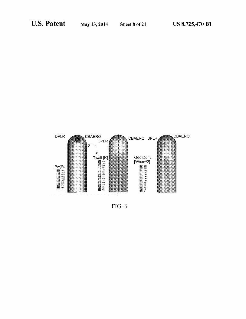
FIG. 5 briefly illustrates an MDO Cobra analysis process. FIG. 6 compares aerothermal values between a DPLR
Code and a CBAERO Code. FIGS. 7A-7D graphically illustrate altitude versus veloc-
ity, and dynamic pressure, lift and drag coefficients versus time for a typical trajectory.
FIG. 8 illustrates zone assignments for a surface of a rep-resentative vehicle.
FIG. 9 illustrates TPS sizing results according to the inven-tion.
FIGS. 10 and 11 graphically illustrate initial and final Pareto Front results according to a MOGA shape optimiza-tion.
FIG. 12 compares aerothermal values computed using a CBAERO Code and a DPLR Code.
FIGS. 13A-13C compare flow velocity and temperature versus distance from the surface (dn) and other flow variables for an optimized surface shape.
4 FIGS. 14A-14D compare trajectories for three optimized
shapes with trajectories for the 1000 Ellipsled POD. FIGS. 15A-15B compare integrated heat load plots and
TPS thicknesses for the three optimized shapes with corre- 5 sponding values for the 1000 Ellipsled POD.
FIGS. 16 and 17 compare heat loads and TPS thicknesses for different surface shapes.
FIGS. 18,19 and 20 illustrate three procedures for practic-ing the invention.
10
DESCRIPTION OF BEST MODES OF THE INVENTION
The present invention is a blunt body hypersonic atmo- 15 spheric vehicle of a shape, derived from the COBRASQ
parametric geometric class described in the following, which can be used in a multi-discipline optimization design method in a manner similar as described making use of said paramet-ric geometric class of shapes. The particular parametric form
20 or shape of the vehicle heat shield provides a motivation for the invention and meets the need for an optimizable shape with favorable aerodynamic and heating level properties.
The COBRASQ class of geometries is intended to generate an outer shape suitable for operation as a mid-L/D ratio,
25 hypersonic reentry blunt body vehicle and is constructed using piecewise analytical surfaces or segments joined together with at least Cl continuity at definable seam lines. An exception to the Cl continuity condition is at the base seam, which need only be CO continuous. At launch, the
30 COBRASQ class of geometries is normally intended for its lengthwise x-axis to be aligned vertically coincident with the vertical launch axis of the launch vehicle. On atmospheric entry, the COBRASQ class of geometries are intended to be oriented at a substantial angle of attack a with the windward
35 side (z>O) presented to the oncoming atmosphere. In FIGS. 2A, 2B and 2C, the geometries are illustrated
along with Cartesian coordinate system (x,y,z). The x-axis is oriented along the lengthwise axis of the vehicle with the nose being in the positive x-direction and the aft-body and base
4o being oriented towards the negative x-direction. The positive y-axis is oriented toward the right of the vehicle (facing forward), and the positive z-axis is oriented so the vehicle is pointed in what will generally be the windward direction when the vehicle is at a positive angle-of-attack (AoA).
45 The vehicle shape is shown in FIGS. 1A, 113, 1C, as com- posed of the several surface and seam line segments:
a. Windward Forebody or Nose section (z>O, and approxi-mately x>O),
b. Leeward Forebody or Nose section (z<O, and approxi-50 mately x>O),
c. Windward Aftbody Section (z>O, and approximately x<O),
d. LeewardAftbody Section (z<O, and approximately x<O), and
55 e. Base Rib Section, being the rib section or yz-plane cut of constant x at the most rearward location (x=x,).
The Seam lines where these segments join are: 1. Fore/Aft Seam (at approximately x -0), 2. Waterline Seam, defined at z -0, for regions with z>O
6o being windward sections, and z<O being leeward sections; 3. Upper or Leeward Keel or Spine, defined as the curve or
line segments at y-0 for regions with z<O; and 4. Lower or Windward Keel or Spine, defined as the curve
or line segments at y-0 for z>O. 65 The surface segments can be described by a collection of
super-quadric surfaces, with the curve seams being defined by a collection of curve segments, either linear or curvilinear.

US 8,725,470 B1 5
6 Without loss of generality, in a preferred embodiment, the each cut being composed of a continuous concatenation of at upper Nose section (FIG. 2A), both windward and leeward, is least two segments. The upper Keel line segments are defined defined by a super-quadric of the following form: by
(x/xl) ai+((Y/yl) bi +(z/zl) b1 1 11/bi=1 (3) 6 (x/x7)a 7+(z/z7)a 7=1, for x>x(UpperKeelTangentPt),
with y=0,z>0 (9)
where x1, y and A are specified semi-lengths and al and b are specified exponents, both greater than 1. FIGS. 3A, 3B and 3C graphically illustrate a two-dimensional representa-tion of a super-quadric with a=b=1.5, 2.0 (ellipse) and 2.5 for comparison. In FIG. 2A, the lower Nose section is similarly defined as
(x/x2)a2+{(y1y2)b2+(z1z2)b2] 21b2_l, (4)
where x2=xl, y2=yl, and a2-al (>1) are required for Cl continuity, and A and z2 are independently specified semi-lengths, andbI andb2 are independently specified exponents, greater than 1.
The origin of the super-quadric is positioned at (x,y,z)=(0, 0,0) with the most forward point on the nose section being at (x1,0,0). Each of the upper and lower Nose sections thus defined is symmetric about the xz-plane. Where the expo-nents, al, bl, a2 and b2, are all equal to 2.0, and x1=y1=z1=x2=y2=z2, a simple hemispherical nose is obtained as a geometrically degenerate case.
The upper base rib (located at x=-xL), is a super-quadric planar surface, as shown in FIG. 2B and defined by:
(y/y3)b3+(z1z3)b3=1, (5)
where y3 and z3 are specified semi-axis lengths of the body surface in the yz-plane, and the specified base exponent b3 is also specified but must be >l. The lower base rib (located at x=-xL), is a super-quadric planar surface, as shown in FIG. 213) and is similarly defined by:
z==z7(x),forx<x(UpperKee1TangentPt),withy -O,z>0 (10)
and the lower Keel line segments are defined by
10 (x/x8) a8+(z/z8) °$=1, for x>x(LowerKeelTangentPt), with y=0,z<0 (11)
z=z8(x),forx<x(UpperKee1TangentPt),withy=0,z<0 (12)
where the first curve segment for each of the upper and lower 15 Keel lines (Eqs. (7) and (9), respectively) is a super-quadric
segment contribution from the Nose super-quadric and the second curve for each of the upper and lower Keel lines (Eqs. (8) and (10), respectively) are straight lines (or splines, if desired) that are constructed to be tangent to the super-quad-
2o ric Nose segment and to pass through the Base Rib segment at (-xL,0,-z3) and (-xL,0,z4), respectively. The exponents a5, a7 and a9 will all be equal to al, the parameters x5, x7 and x9 will all be equal to xl, and the parameter z7 and z8 will be equal to A and z2, respectively, as these correspond to con-
25 tributions from the Nose segment(s). The tangent point location(s), expressed as x(WaterlineT-
angentPt), x(UpperKeelTangentPt), and x(LowerKeelTan-gentPt) are found by analytical or known iterative numerical methods to enforce at least Cl continuity for the Waterline,
30 Upper Keel line and Lower Keel line. Thus, the (upper/lower) Keel-line segments canbe found at
any x-station as given above, and will be defined hereafter by the general equations
z(xy=0)=z(UpperKeelLine(x)),for xi >x>-xt,and
(y1y4)b4+(z1z4) b4=1. (6) 35 z<0, (13)
The origin of the base rib is located at (x,y,z)=(-x L,0,0), and for continuity y3 -y4, but z3 and z4 and b3 and b4 may be specified independently. The geometrically degenerate case of a circle is obtained with y3 -z3-y4-z4 and b3=b4=2. 40
To define the aft-body region between the (upper/lower) Nose section and the (upper/lower) Base Rib section, both the Waterline curve segment and the (upper/lower) Keel curve segments must first be defined.
The Waterline curve segment is shown in FIG. 2C as an 45 xy-planar cut through the vehicle shape at z -0. In the pre-ferred embodiment, the Water line will be a continuous con-catenation of at least two surface segments, defined by
x/x5)a 5+(y1y5)a5=l, for xax(WaterlineTangentPt),with 50
z=0 (7)
y=y6(x),for x<x(WaterlineTangentPtwith z=0, (8)
where the first Waterline curve segment, Eq. (7), for x>x (WaterlineTangentPt) is a super-quadric segment contribu- 55
tion from the Nose super-quadric, and the second Water line curve segment, Eq. (6), for x<x(WaterlineTangentPt), is a linear segment (or spline segment, if desired) that is con-structed to be tangent to the Nose super-ellipse and passes through the Base Rib at (x--xL, y3, 0). The tangent point, at 60
x(WaterlineTangentPt), can be found analytically or by itera-tive numerical means. Thus, the Waterline segment can be found at any x-station as given above and will be referred hereafter by the general equation, y(x,zO)=yWaterLine(x).
The upper and lower Keel lines are treated similarly to the 65
Water line and are shown in FIG. 2C, which shows sectional views from a xz-planar cut through the vehicle shape at y -0,
z(xy=0)=z(LowerKeeLine(x)),forxl>x>-xt,andz>0. (14)
The Aft-body, shown in FIG. 2C, is specified for each point on the surface by the following procedure. For the Aft-body, at any given x-station, the yz-cut through the vehicle shape will be given by an upper and lower super-equadric rib defined by
{(y/y(Waterline(x)) b9( )+(z/zUpperKeelLine(x)} b9(x) =1, (15)
{(y/y(Waterline(x)) bio( )+(z/zLowerKee1Line(x)} bio(x)
=1, (16)
where the exponents b9 (x) or b 10(x) are found by any known continuous curves (spline, cosine, or linear) segments passing from b10(x)=b1 at the greater x-value of x(WaterlineTan-gentPt) and x(UpperKeelTangentPt), and b9(x)=b3 at x=-x L .
Similarly, the exponent bl0(x) is found by any known (spline, cosine or linear) continuous curve segments passing from b I (x)=b I at the greater x-value of x(WaterlineTangentPt) and x(LowerKeelTangentPt), and b10(x)=b4 at x=-x L . The vehicle is symmetric about the xz-plane at y -0.
Using the above procedure at any x-station, each rib or (x,z) curve of the Aft-body can be described entirely and without ambiguity, and such a vehicle shape is C2 continuous, except at the seam lines given above, where it is Cl continuous. In the preferred embodiment described above it appears sufficient to specify the parameters, {xL,xl-x10, yl-y10,zl-z10, al-a10, bl-b10} to entirely determine the vehicle shape. All other parameters mentioned in the description of the preferred embodiment may be derived during execution of the proce-dure described above.

US 8,725,470 B1 7
A Fortran-based COBRASQ.F program implements the preceding procedure and provides a surface grid, as either a structured P1ot3D ASCII text file, or as an unstructured sur-face mesh file suitable for with the CBAero engineering analysis program, or as an unstructured Tecplot ASCII text 5
file suitable for plotting, using commonly available visualiza-tion software such as either P1ot3D or Tecplot.
Such a surface grid can be generated with human interven-tion or without human intervention by means of a Multi-discipline Design Optimization procedure by providing a io limited number of intuitive parameters, such as for a shape symmetric about the yz-plane. Although the number of sur-face segments discussed in the preceding is 6, the vehicle surface may be defined more generally by M surface seg-ments, with M>_1. 15
For this particular instance of the invention (with M=6), a minimum of 15 independent parameters define the vehicle shape from which surface grids can be automatically gener-ated. This number of independent parameters may be large or smaller than 15, depending upon the number M of surface 20
segments. Such surface grids can also be used with engineering-
fidelity analysis codes such as CBAERO to provide wall pressure and heating, hypersonic aerodynamic properties such as lift and drag and stability, and structural codes such as 25
MSC NASTRAN to provide structural strength and mass estimates of such a body, or to provide a basis for generating volume grids capable of use with hi-fidelity Real-Gas Navier-Stokes fluid mechanics and chemistry codes such as DPLR.
Note that, as shown in FIGS. 3A, 3B and 3C, when the 30
super-quadric exponents, a and b are equal to 2.0, an ellipse is formed; whereas when a and b are less than 2.0 and near 1.0, the cross-sectional shape generated approaches a rhombus; and if they are much greater than 2.0, the cross-sectional shape becomes increasingly rectangular. As a consequence, a 35
large class of practical 3D shapes, suitable for study as pos-sible hypersonic re-entry vehicles, can be configured by means of the above sets of geometric parameters and meth-ods.
The general parametric shape of the present invention 40
defines the vehicle shape without the need for intense human labor, which allows for automated optimization or search throughout a large variety of possible shapes in order to find the best aerodynamic, aerothermal properties, including sta-bility, lift, drag, both convective and gas-phase radiation heat- 45
ing. The disclosed Multi-disciplinary Design Optimization
(MDO) framework takes account of the aeroshell shape, tra-jectory, thermal protection system, and vehicle subsystem closure, along with a Multi Objective Genetic Algorithm 50
(MOGA) for the initial shape. This is accomplished using a combination of engineering and higher-fidelity physics-based tools along with optimization methods and engineering judgment. This process demonstrates that the proposed fam-ily of optimized medium L/D aeroshell shapes exhibits a 55
significant improvement over the present art. Further, a trade-off between the vehicle TPS and structural mass is identified for these aeroshell shapes and their corresponding vehicle trajectories which yields an overall decrease in total vehicle mass, or a corresponding increase in delivered payload, as 60
compared to the state of the art. As an entry vehicle's aeroshell becomes larger, the Rey-
nolds Number (Re) increases, causing the flow to become turbulent. Studies have shown that the legacy Viking 70-de-gree sphere-cone aeroshell shape, classically used for entry 65
into Mars, exhibits high turbulent heating levels on the lee-ward side as well as early transition to a turbulent flow for
8 large diameters. This phenomenon has especially impacted the planned Mars Science Laboratory (MSL) aeroshell, also a 70-degree sphere-cone shape, which is predicted to experi-ence a peak margin heating rate approaching 200 Watts/cm 2 during entry. This maximum heating occurs on the leeward side of the fore-body aeroshell, and reaches heating augmen-tation levels up to a factor of six higher than laminar heating levels rather than the expected turbulent heating increase by a factor of three. This high leeward side aeroshell turbulent heating has been attributed [1,2] to entropy layer swallowing effects associated with the legacy 70-degree shape at high Reynolds number, Mach number and angle of attack. The high turbulence-induced heating rates on the MSL aeroshell were a primary reason that the MSL program changed its thermal protection system (TPS) material from lighter SLA-561 V to more robust PICA in 2008. The PICA material, in one embodiment, is described in U.S. Pat. Nos. 5,536,562, 5,672,389 and 6,955,853, issued to Tran et al and incorpo-rated by reference herein.
The aeroshell shape affects several primary design areas for hypersonic entry vehicles. This includes the aerothermal environment which determines vehicle's TPS layout and design, the aerodynamics which affects deceleration and maneuverability coupled with trajectory shaping and the aerodynamic loading which affects the underlying structural subsystem. Because of this, it is crucial that alternate aero-shell designs account for these multiple disciplines in order to evaluate them in a system level view and to understand how each subsystem is affected. In order to do this and to explore the design space, an integrated Multi-disciplinary Design Optimization (MDO) technique accounting for shape, trajec-tory, thermal protection system (TPS), and vehicle closure was utilized in this effort. A combination of engineering and higher-fidelity physics analysis tools along with optimization methods and engineering judgment is used to accomplish a system level view and lead to a multi-discipline solution. The integrated MDO process environment allows engineers to efficiently and consistently analyze multiple design options. In addition, this integrated MDO framework allows for assessing the relative impacts of new discipline tool capabili-ties and identifying trade-offs between multiple objectives through the use of the Genetic Algorithm (GA) optimization Pareto front. The framework described is referred to as COBRA, an acronym for "Co-Optimization of Blunt-body Re-entry Analysis"[3]. Vehicle Geometry.
The vehicle geometry is based on one of several FOR-TRAN codes written specifically to provide an analytic description of the vehicle shape with a small number of geo-metric parameters. Shape examples are shown in FIGS. 1A-1C.
These codes that can be used to define a geometry include: 1) a low-L/D, high-ballistic coefficient symmetric/asymmet-ric capsule body code [4,5]; 2) a medium L/D lifting body code as described above, or 3) a low-L/D, Apollo/CEV-type truncated-sphere/torus capsule shape code. Each code can generate surface mesh descriptions in either structured Plot3 d or as unstructured triangulations of the surface shape. These codes allow the use of a small set of geometric parameters to define the vehicle's outer mold line (OML) and to provide shapes with a range of aerodynamic and aerothermodynamic properties useful for optimization. The general parametric shapes of the COBRA process entirely define the vehicle shape without the need for intense human interaction. This reduction in direct interaction allows for automated optimi-

US 8,725,470 B1 9
10 zation within a large design space to find the best combination configuration is the structure of the aeroshell. The structure of aerodynamic stability and aeroheating for the vehicle per- mass is determined, not only by the aeroshell configuration, formance. but also by the aerodynamic loading, vehicle scale, and pay- Aerodynamic s/Aerothermodynamics. load configuration. This presents a serious problem when
The aerodynamic and aerothermodynamic characteristics 5 performing a design space exploration or stochastic optimi- of each particular vehicle shape are computed using either the zation where the configuration of the conceptual vehicle is CBAERO engineering code [6] and/or the DPLR [7] Com- allowed to vary largely. Traditionally, the options available putational Fluid Dynamic (CFD) code. CBAERO is an engi- are: (1) to apply existing Mass Estimating Relations (MERs), neering analysis code based on independent panel methods, (2) to extrapolate from similar vehicle designs, and (3) to such as the modified Newtonian method, along with a surface io select a general vehicle configuration and generate a param- streamline algorithm and an extensive set of validated engi- eterized mass model to be used in the analysis. In some cases neering correlations to determine surface pressure, convec- these approaches are suitable. However, there are situations tive and radiative heating, shear stress, and boundary layer when there are no MERs available for a given configuration, properties. DPLR is a high-fidelity, physics-based real-gas or the existing ones have to be extrapolated to such an extent Navier-Stokes code used in conjunction with NEQAIR [8], a 15 that their associated error is either unknown or unacceptable. high-fidelity radiation code, to give results either in support of
In many cases, larger margins are applied to the structures,
or in place of CBAERO data. making the structures infeasible as far as mass is concerned. It is in this discipline that a hybrid approach which lever- To address these issues, in this work, a structure module has
ages high fidelity analyses with engineering methods using
been developed to allow for direct simulation and optimiza- sophisticated interpolation techniques, ("anchoring"), is uti- 20 tion of the vehicle structure components using automated lized. Traditionally, analytical tools applied in the early scripts. This is done by extracting the pressure load from the phases of vehicle design rely on engineering methods engineering aerodynamic tool, assigning structure elements because of their rapid turnaround time, ease of use, and
for each aeroshell shape, and performing a structural optimi-
robustness. The drawbacks of engineering methods are that zation to minimize the structural subsystem mass using MSC such methods only approximate the physics governing the 25 NASTRAN [I I]. process to be modeled and such methods may not accurately
Thermal Protection System Sizing.
model the flow physics. Unlike engineering methods, high
To assess the thermal protection system (TPS), the nominal fidelity methods are based on solutions to the basic equations trajectory for each shape is generated and its aerodynamic of physics to be modeled and yield more accurate results, if
and aeroheating characteristics, including the time history of
used within their limitations. However, these high fidelity 30 the heating environments, are providedto the TPSSIZER [12] methods tend to be difficult to set up and computationally set of programs. TPSSIZER includes the FIAT [13] thermal expensive (typically hundreds of times more CPU-intensive analysis code for ablative TPS materials. The result is an than engineering methods). The anchoring approach
optimized TPS sizing for a vehicle shape with its own nomi-
addresses the deficiencies with the engineering and high
nal trajectory for the mission constraints being considered. fidelity methods by utilizing a rapid and intelligent engineer- 35 The TPS sizing process begins by computing the maximum ing-based interpolation method. Further detail of this anchor- temperature and integrated heat load for each point on the ing approach can be found in Reference [9]. surface of the vehicle. This is done by simulating flight by Trajectory Analysis. each surface geometry through the aerocapture, cool-off, and
During optimization of the vehicle, the nominal design entry trajectory phases, by interpolating in Mach number, trajectory is dependent on the aerodynamic and aeroheating 4o dynamic pressure, and angle-of-attack within the CBAERO properties of the particular vehicle shape, in particular, L/D, aerothermal database at each trajectory time step. Appropri- ballistic coefficient, and peak heating. Constraints on the ate design margins are applied to the heating rates based on trajectory flight dynamics, such as gravitational loading on those developed for the NASA Orion capsule [14]. The TPS the vehicle, also must be imposed. To find a nominal trajec- material distribution is determined by the maximum heating/ tory for each vehicle under consideration, the Program to 45 temperature for each body point. Approximately 10 to 20 TPS Optimize Simulated Trajectories (POST2) [10] code is used. sizing points are selected for each body region based on
In this work, the trajectory used for entry and landing on a maximum integrated heat load values. Detailed heating envi- surface of a planetary body consists of two phases: (1) an ronments as a function of time are generated for the TPS initial aerocapture phase to decelerate the entry vehicle into a sizing body points. For each TPS sizing point, the corre- 1-SOL orbit about the Martian atmosphere; and (2) an entry 50 sponding thermal analysis material stack-up is created, phase down to the surface. Both trajectories are modeled with
reflecting the TPS material concept and the associated aero-
3DOF. POST2 is wrapped inside the COBRA environment to shell structural definition, and including sublayer material expose input parameters necessary to simulate the aerocap- thicknesses determined by the structural analysis. At each ture and entry trajectories. By exposing a limited set of input sizing point, a transient heat transfer analysis is computed that variables from POST2, the trajectory wrapper greatly simpli- 55 varies the insulation thickness until the desired back wall fies the tedious work for the analyst and makes it suitable for temperature limit is satisfied. This process is repeated for all integrations into the COBRA environment. However, it does
body TPS sizing points and the TPS mass is computed assum-
not replace critical expert judgment. Results should be care- ing uniform insulation thickness over each body zone. fully inspected to ensure correctness. The wrapper also
Vehicle Mass and Sizing.
exposes output variables needed for downstream tools such as 60 Among the constraints for optimization of a mission being TPS sizing, structure, and the weight and sizing closure tools. considered are the particular launch vehicle, payload fairing, Structure Analysis. and delivered vehicle total mass at entry interface for the
In performing conceptual design on a vehicle that does not planetary body of interest. Combining the TPS sizing closely resemble one which has flown before, or that has obtained from TPSSIZER and the propellant mass estimate undergone higher fidelity analysis, it can be difficult to 65 for the trajectory tool POST2, the weight/sizing vehicle clo- develop appropriate mass predictions for the vehicle compo- sure analysis code, XWAT/XClosure [15] provides an esti- nents. One component which is very sensitive to the vehicle mate of the delivered payload for the particular vehicle shape
US 8,725,470 B1 11
12 parameters selected by the MDO analysis. XWAT, the XML
Summaries of some of the computer codes (COBRASQ,
based Weight/Mass Analysis Tool, is an XML based C++
CBAERO, DPLR, POST2, 3DOF, TPSSIZER, FIAT, MER, application to compute mass/sizing of any space vehicle con- MSC NASTRAN, XWAT/XClosure, EDL-SA and ADB) cept. XWAT can be applied, not only to launch vehicles, but used here are contained in an Appendix. Alternate MDO also EDL studies. For our study, the MER's and associated 5 algorithms, as known to the practitioners of the art, can be parameters for all the major subsystem elements are collected
substituted for the GA optimization algorithm.
in an XML format within the LUL framework. Several of the
MDO Overview. subsystem MER's depend on the total entry mass, resulting in
An overview of the COBRA integrated system optimiza-
an implicit dependence. XWAT tries to solve a fully nonlinear tion analysis environment based on the discipline tools dis- mass equation system by iterating on the total entry mass until io cussed above is illustrated in FIGS. 2A-2C and 3A-3C. The the masses of all the subsystems converge. Upon conver- COBRA environment, as configured, allows for either a top gence, XWAT produces a mass and volume statement for the
down approach to determine the maximum landed payload
closed configuration. In this work, the payload mass is pre- mass for a given entry total entry vehicle mass, or a bottom up scribed and the total entry vehicle mass is computed using the approach to determine the required entry vehicle mass for a XWAT program. Optimization of either the maximum deliv- 15 given landed payload. Here, a bottom up approach is used ered payload or the minimum entry vehicle mass (where a where the landed payload required is specified, and the co- payload is specified), becomes an objective function for the optimization process is to minimize the entry vehicle mass at COBRA MDO environment. atmospheric entry. Shape Optimization. The global system optimization is achieved through a mul-
Shape optimization is performed using a Multi Objective 20 tistep process. The MOGA driver is used to find a Pareto front Genetic Algorithm optimization (MOGA) package within the among the allowed range of vehicle shape parameters being DAKOTA tools suite [16]. The basic idea associated with a considered using engineering fidelity analysis tools to genetic algorithm ("GA") approach is to search for a set of
explore the initial vehicle shape design space. This is fol-
optimal solutions using an analogy to the theory of evolution. lowed by an integrated MDO analysis including structures, The problem is parameterized into a set of design variables, 25 trajectory, and TPS sizing, followed by a weight and sizing also referred to as "genes." Each set of design variables that analysis to perform the final vehicle closure. fully defines one design is called a design or a chromosome. COBRA Environment CalibrationNerification. A set of chromosomes is called a population or a generation. Because of the complexity of integrating the MDO analy- Each design or chromosome is evaluated using a fitness func- sis, it is critical that experts in different disciplines are tion that determines survivability of that particular chromo- 30 involved in both the setup and verification of the results being some. In this invention, the genes are a series of geometric generated. For our work we selected the EDL-SA rigid aero- parameters associated with the aeroshell outer-mode-line shell Architecture 1 as described in Reference [20] as the (OML) and are optimized to meet two thermal objectives. point of departure (POD) for our baseline. Under the EDL- Each evaluation is performed at a single trajectory point
SA, multiple architectures are explored. The rigid aeroshell
based on what is expected to be the maximum heat flux 35 configuration was based on a vehicle with an outer model line experienced by an entry vehicle into Mars. This maximum
(OML) shape including a 5-meter radius hemispherical nose
heat flux for the baseline 1000 simple Ellipsled has been with a cylindrical aft-body of diameter 10 meters and length determined to occur during the Aerocapture trajectory phase of 25 meters yielding a total vehicle length of 30 meters, at a Maxh number of approximately 32.0 and dynamic pres- referred to in our work as the 10x30 Ellipsled. This process sure of 0.15 bars. The GA function evaluation is performed at 40 provides a means to allow us to perform a verification analysis the flight conditions set forth in the preceding for a vehicle and to setup and calibrate the trajectory and MERs for the trim alpha design such that its aerodynamics achieves a lift- chosen baseline. Each of the technical discipline analyses is to-drag ratio of 0.5. performed independently on the baseline configuration and
The two objectives are (1) to minimize the peak total heat
the results are compared to values reported in [20]. This flux on the vehicle and (2) to maximize the drag area (C DA). 45 process is also used to provide a point of departure (POD) for Maximizing CdA leads to a minimization of ballistic coeffi- the aeroshell shape optimization and the subsequent inte- cient. During solution advancement, each chromosome is grated system analysis. ranked according to its fitness. The higher-ranking chromo- 1000 Ellipsled High FidelityPOD Comparison of Engineer- somes are selected and continue to the next generation. The
ing Aero/Aerothermal.
newly selected chromosomes in the next generation are 50 To assess the accuracy of the CBAERO engineering tool, manipulated using various operators (combination, crossover the aerodynamics and aerothermal heating on our POD archi- or mutation) to create the final set of chromosomes for the tecture must be evaluated. To accomplish this, a comparison new generation. These chromosomes are evaluated for fitness of the surface pressure, surface temperatures and convective and the process continues until a suitable level of convergence
heating is performed against a high fidelity DPLR simulation
is obtained. 55 as shown in FIG. 4. This comparison is performed at a Mach Constraints are included in the GA optimization approach, number of 32.5, dynamic pressure of 0.114 bar, and angle-
either by direct inclusion into the objective function definition of-attack of 56.4 degrees. These qualitative comparisons as penalty constraints, or by including them into a fitness
illustrate that the engineering CBAERO results compare well
function evaluation procedure. For example, if a design vio- with DPLR for this geometry. lates a constraint, its fitness is set to zero, and the design does 60 FIG. 5 illustrates a system for practicing the invention. not survive to the next generation. Because GA optimization
1000 Ellipsled POD Trajectories.
is not a gradient-based optimization technique, it does not
The trajectory is divided into energy phases using the ini- need sensitivity derivatives. GA theoretically works well in tial and final energy states. In the COBRA environment, non-smooth design spaces containing many local minimums
POST2 modulates the bank angles to achieve the final condi-
and maximums. General GA details, including descriptions 65 tions while trying to satisfy a set of constraints. The aerocap- of basic genetic algorithm concepts, can be found in Refer- ture trajectory is formulated as a targeting problem. For this ences [18] and [19]. work, the entry trajectory is run with a reference stagnation
US 8,725,470 B1 13
14 heat load minimization option. Other options include: maxi-mizing the landed mass, or optimizing a user defined variable through a generalized table. The aerocapture trajectory can also be constrained with specified minimum altitude, maxi-mum g-load, and maximum heat flux. The entry trajectory is constrained with maximum g-load, maximum heat flux, maximum q-alpha, freestream dynamic pressure and cross/ down range to achieve the same retro rocket initiation as is utilized in the EDL-SA effort documented in Reference [19].
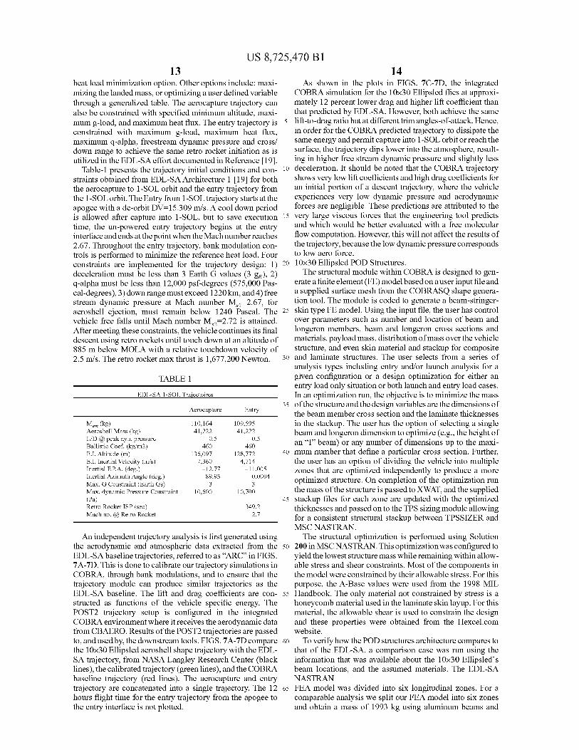
Table-1 presents the trajectory initial conditions and con-straints obtained from EDL-SA Architecture 1 [19] for both the aerocapture to 1-SOL orbit and the entry trajectory from the 1-SOL orbit. The Entry from 1-SOL trajectory starts at the apogee with a de-orbit DV=15.309 m/s. A cool down period is allowed after capture into 1-SOL, but to save execution time, the un-powered entry trajectory begins at the entry interface and ends at the point when the Mach number reaches 2.67. Throughout the entry trajectory, bank modulation con-trols is performed to minimize the reference heat load. Four constraints are implemented for the trajectory design: 1) deceleration must be less than 3 Earth G values (3 g,), 2) q-alpha must be less than 12,000 psf-degrees (575,000 Pas-cal-degrees), 3) downrange must exceed 1220 km, and 4) free stream dynamic pressure at Mach number M,, -2.67, for aeroshell ejection, must remain below 1240 Pascal. The vehicle free falls until Mach number M,2-2.72 is attained. After meeting these constraints, the vehicle continues its final descent using retro rockets until touch down at an altitude of 885 m below MOLA with a relative touchdown velocity of 2.5 m/s. The retro rocket max thrust is 1,677,200 Newton.
TABLE 1
EDL-SA 1-SOL Traiectoires
Aerocapture Entry
M_ (kg) 110,164 109,595 Aeroshell Mass (kg) 41,222 41,222 L/D @ peak dyn. pressure 0.5 0.5 Ballistic Coef. (kg/m2) 460 460 E.I. Altitude (m) 136,097 128,772 E.I. Inertial Velocity (m/s) 7,360 4,714 Inertial F.P.A. (deg.) —12.77 —11.005 Inertial Azimuth Angle (deg.) 89.93 0.0004 Max. G Constraint (Earth Gs) 3 3 Max. dynamic Pressure Constraint 10,600 10,700 (Pa) Retro Rocket ISP (sec) 349.2 Mach no. @ Retro Rocket 2.7
An independent trajectory analysis is first generated using the aerodynamic and atmospheric data extracted from the EDL-SA baseline trajectories, referred to as `ARC" in FIGS. 7A-7D. This is done to calibrate our trajectory simulations in COBRA, through bank modulations, and to ensure that the trajectory module can produce similar trajectories as the EDL-SA baseline. The lift and drag coefficients are con-structed as functions of the vehicle specific energy. The POST2 trajectory setup is configured in the integrated COBRA environment where it receives the aerodynamic data from CBAERO. Results of the POST2 trajectories are passed to, and used by, the downstream tools. FIGS. 7A-7D compare the 1000 Ellipsled aeroshell shape trajectory with the EDL-SA trajectory, from NASA Langley Research Center (black lines), the calibrated trajectory (green lines), and the COBRA baseline trajectory (red lines). The aerocapture and entry trajectory are concatenated into a single trajectory. The 12 hours flight time for the entry trajectory from the apogee to the entry interface is not plotted.
As shown in the plots in FIGS. 7C-7D, the integrated COBRA simulation for the 1000 Ellipsled flies at approxi-mately 12 percent lower drag and higher lift coefficient than that predicted by EDL-SA. However, both achieve the same
5 lift-to-drag ratio but at different trim angles-of-attack. Hence, in order for the COBRA predicted trajectory to dissipate the same energy and permit capture into 1-SOL orbit or reach the surface, the trajectory dips lower into the atmosphere, result-ing in higher free stream dynamic pressure and slightly less
to deceleration. It should be noted that the COBRA trajectory shows very low lift coefficients and high drag coefficients for an initial portion of a descent trajectory, where the vehicle experiences very low dynamic pressure and aerodynamic forces are negligible. These predictions are attributed to the
15 very large viscous forces that the engineering tool predicts and which would be better evaluated with a free molecular flow computation. However, this will not affect the results of the trajectory, because the low dynamic pressure corresponds to low aero force.
20 1000 Ellipsled POD Structures. The structural module within COBRA is designed to gen-
erate a finite element (FE) model based on a user input file and a supplied surface mesh from the COBRASQ shape genera-tion tool. The module is coded to generate a beam-stringer-
25 skin type FE model. Using the input file, the user has control over parameters such as number and location of beam and longeron members, beam and longeron cross sections and materials, payload mass, distribution of mass over the vehicle structure, and even skin material and stackup for composite
3o and laminate structures. The user selects from a series of analysis types including entry and/or launch analysis for a given configuration or a design optimization for either an entry load only situation or both launch and entry load cases. In an optimization run, the objective is to minimize the mass
35 of the structure and the design variables are the dimensions of the beam member cross section and the laminate thicknesses in the stackup. The user has the option of selecting a single beam and longeron dimension to optimize (e.g., the height of an "I" beam) or any number of dimensions up to the maxi-
40 mum number that define a particular cross section. Further, the user has an option of dividing the vehicle into multiple zones that are optimized independently to produce a more optimized structure. On completion of the optimization run the mass of the structure is passed to XWAT, and the supplied
45 stackup files for each zone are updated with the optimized thicknesses and passed on to the TPS sizing module allowing for a consistent structural stackup between TPSSIZER and MSC NASTRAN.
The structural optimization is performed using Solution 5o 200 in MSC NASTRAN. This optimizationwas configuredto
yield the lowest structure mass while remaining within allow-able stress and shear constraints. Most of the components in the model were constrained by their allowable stress. For this purpose, the A-Base values were used from the 1998 MIL
55 Handbook. The only material not constrained by stress is a honeycomb material used in the laminate skin layup. For this material, the allowable shear is used to constrain the design and these properties were obtained from the Hexcel.com website.
60 To verify how the POD structures architecture compares to that of the EDL-SA, a comparison case was run using the information that was available about the 1000 Ellipsled's beam locations, and the assumed materials. The EDL-SA NASTRAN
65 FEA model was divided into six longitudinal zones. For a comparable analysis we split our FEA model into six zones and obtain a mass of 1993 kg using aluminum beams and

US 8,725,470 B1 15
longerons and a composite laminate for the skin. Dividing the vehicle up differently may lead to a more optimal shape. By applying a ten-zone decomposition to the vehicle, as opposed to six zones (five windward zones and five leeward zones), as shown in FIG. 8, the optimized mass is brought down to 4333 kg. 10x30 Ellipsled POD Thermal Protection Systems Sizing.
Initially MER's were developed for the Thermal Protection System mass as part of the overall entry mass calibration process discussed in the preceding. The baseline TPS concept for the Mars EDL-SA vehicle consists of a dual-layer TPS concept, made up of an outer ablative TPS layer to accom-modate the high heating rates encountered during the aero-capture phase, with a lighter weight sublayer TPS material to address the more benign aerothermal environments of entry. For the current shape optimization trade study, a more con-ventional single layer TPS concept was selected. This resulted in a simplification of the TPS design analysis by avoiding the complication of modeling the dual layer concept without impacting the relative comparison between the vary-ing geometric configurations (effects of modifying the aero-shell shape to infer how it will affect the TPS mass).
The TPSSIZER code is used to conduct the TPS sizing for the entry vehicle. The TPS sizing trajectory includes the initial aerocapture phase concatenated with the 1-Sol entry trajectory, with an intermediate cool down period. This cool-down allows the TPS and structure to re-radiate the aerocap-ture heat pulse and return to the initial pre-entry temperature distribution. Due to the magnitude of the convective and shock-layer heating incurred during aerocapture, Phenolic Impregnated Carbon Ablator (PICA) is selected for wind-ward applications, with Shuttle derived ceramic tile (LI-900) used on the cooler leeward surfaces.
For the baseline 1000 Ellipsled configuration, the result-ing TPS material distribution includes 493.7 m 2 of LI-900 the and 527.3 m2 of PICA. Maximum RSS PICA thickness is 14.8 cm, with an average a real thickness of 8.16 cm. Maxi-mum thickness for the LI-900 tile is 3.37 cm, with most of the LI-900 tile at minimum gauge thickness. The TPS windward splitline and thickness distributions are shown in FIG. 7. Total LI-900 mass is 1170 kg, with an average areal unit mass of 2.37 kg/m2 and total PICA mass is 12,188 kg, with an average areal unit mass of 23.11 kg/m 2 . The net total TPS mass is 13358 kg with an average areal unit mass of 12.63 kg/m 2 . This compares with a total TPS mass for the dual-layer concept, used by EDL-SA, of 9,217 kg at an areal unit mass of 8.96 kg/m2 . It should also be noted that the structural concept for the baseline EDL-SA Ellipsled is titanium skin-stringer with an allowable 560° K back-face temperature. By comparison, the POD Ellipsled aeroshell is composite honeycomb with an allowable maximum temperature of 450° K. 10x30 Ellipsled POD Entry Vehicle Mass Estimates.
The entry vehicle total mass was computed using Mass Estimating Relationships (MER's) developed at the major subsystem level for the 40 MT payload Ellipsled configura-tion, including structures, induced environments, DHCC, auxiliary systems (separation system), RCS, prime power generation and distribution, surface control actuation and RCS propellant. Fixed masses included the lander vehicle and payload. The form of the MER's was derived from Reference [20], with the leading coefficients calibrated to replicate the Mars EDL Architecture No. 1 subsystem weight statement [20]. Mass growth allowance of 15 percent was applied to all dry subsystem masses.
As an example, the aeroshell structural mass is estimated using the unit areal structural mass (UWT_BodyR..E) pre-sented in Reference [20], with correlation parameters derived
16 from the body length/body diameter trade-off study. Addi-tional correlation parameters are applied to reflect variations in entry mass and aero-loading anticipated in the geometry trade/optimization process. The form of the aeroshell struc-
5 tural MER is:
UWT Body=UYVT Body ~F* (LBILB_p 0,967* (DaI
DB-2EF~ 0.988
10 * (m_Entry *gn,,x_L,°(m—EnlrynBF *g,,,,.,a))
0.23
LB REF 30 m
15 DB REF 10 m
m_EntryREE 110100 kg
91.11 REF L,, 2.5 Earth g's)
UWT_BodyREE 5.865 kg/m2
20 All ofthe"REF"values are taken from the reference Archi-tecture No. 1 mass statement and associated trajectory. This form of the structural MER will return the reference unit areal mass with all the parameters set equal to the reference values. Within the shape optimization process, as the geometric
25 parameters change, along with the associated change in the trajectories due to changes in the aerodynamic coefficients with the varied shape, the unit areal structural weight will vary to reflect the geometric and trajectory related parameter variations. This process is generally extended to the other
30 major subsystems through the MER formulation (e.g. surface actuation mass, scaled with maximum free-stream dynamic pressure and body flap planform area).
Using the reference values for the Architecture No. 1 35 Ellipsled as inputs to XWAT, Table 2 compares the XWAT
estimated entry mass with the values from Reference [20], as shown in the second column. The third column presents the XWAT mass estimation using the MER's for all subsystem masses. Ideally the subsystem and total masses should agree.
40 However, differences in assumed parameters, slightly differ-ent WBS definition and the nonlinear nature of the MER's result in non-zero estimated mass differences. As an example, the maximum lateral g-load during entry is found to be 2.79 gE's, as compared to the value of 2.5 gE's used in Reference
45 19. The net result is the XWAT predicted aeroshell mass of 6129 kg, compared to 5980 kg from Reference [20]. Finally, the overall difference in estimated entry vehicle mass is approximately 1 percent.
50 The next step in the analysis process replaces the XWAT MER's for body structure and TPS with the integrated COBRA tools discussed above and re-closes the vehicle. The resulting subsystem masses and vehicle total entry mass are presented in column 3 of Table 2. The TPS mass has
55 increased, reflecting the effects of not using the lighter weight dual-layer TPS system used by the EDL-SA baseline con-figuration. However, some of this mass increase is offset by the lower structural mass with the COBRA vehicle total entry mass being higher by 3,307 kg (3 percent) over the reference
60 vehicle entry mass.
With the calibration of the MER's to reproduce the base-line Mars EDL-SA mass estimate, the XWAT model was integrated into the COBRA environment, with data links
65 established to capture and transmit computed parameters and values to and from the other discipline tools within the design and analysis environment.

US 8,725,470 B1
Mass Element
Mars EDL- SA, kg
XWAT MER,
kg XWAT/COBRA, 5
kg
Body Structure 6417 6695 5983 Aeroshell 5980 6129 5417 Body Flap 437 565 565 Induced Environment 16022 16063 20203 10 Body TPS 9217 9217 13358 Body Flap TPS 390 430 430 Acoustic Blankets 6415 6415 6415 DHCC 228 228 228 Instrumentation 13 13 Auxiliary Systems 1598 1598 1598 15 RCS 4522 4501 4517 Prime Power 62 63 Power 302 322 322 Conversion/Distribution Surface Actuation 442 438 454 Contingency 4430 4486 5011 Dry Mass 33962 34405 38433 20
RCS Propellant 5500 6304 6551 Consumables 23 23 24 Payload 68400 68400 68400 Entry Mass 110100 109133 113407
25
Aeroshell Shape Optimization Results. In order for the shape optimization analysis to be per-
formed, it is important that the objective and constraints for the shape optimization be defined to meet the intended mis-sion requirements. For this analysis, the mission is to land 30
40MT on the surface of Mars using an aerocapture, followed by an entry trajectory as discussed in the preceding. One goal is to minimize the total entry vehicle mass. As discussed in the preceding, we use a multi-objective genetic algorithm (MOGA) approach to perform the shape optimization neces- 35
sary to achieve the objectives. From our POD trajectory results, it has been determined that a good estimate of the peak heating trajectory point occurs at a Mach number of approxi-mately 32.5 and a dynamic pressure of 0.15 bars. In addition a target L/D ratio of 0.5 was chosen to match the L/D used in 40
the EDL-SA work [19]. From these values, a MOGA opti-mizer is run to explore the shape parameter space by utilizing the parametric COBRASQ shape code and the CBAERO engineering aerothermo-dynamics tool. This is done by specifying a set of constraints and objectives with a range of 45
shape parameters for the MOGA optimizer to explore. The constraints for the optimization study are: 1) deter-
mine the number of surface shape triangles which violate the AresV launch fairing envelope limits, 2) impose the condi-tions 3Cm/3oL<0 and 3) 3Cm/3(3<0. The launch fairing tri- 50
angle check is used to assure that the vehicle shapes do not violate the launch fairing payload dynamic envelope. The constraints 3Cm/3oL<0 and 3Cm/3(3c<0 are aerodynamic constraints to assure that the aeroshell shapes are statically stable in the pitch plane (a) and in the yaw plane ((3), respec- 55
tively. The objectives are to minimize the peak total heat flux on the vehicle (Total MaxQdot) and to maximize the drag area (CDA), which correlates directly with how quickly the vehicle will decelerate through the atmosphere before reach-ing the supersonic parachute deployment altitude. Here, 60
higher CDA is desirable. The initial MOGA analysis results in a Pareto front set of
shapes as shown in FIG. 10. Reasonable convergence is seen by the limited change in the Pareto front for 15,000 to 25,000 function evaluations. However, the shapes are found to have 65
very boxy nose shapes, and the flow at the nose has an attach-ment line, not an attachment point. Utilizing engineering
18 judgment/experience we realized that these features would under-predict the heating on the nose with the engineering models and that a better range of shape design parameter for the MOGA optimizer to explore would provide more realistic heating and better predictive capability from the aerothermal engineering model.
The results of the updated MOGA shape optimization are plotted in FIG. 11. Because any point on the plot in FIG. 9 is a potential solution and the Pareto front includes the solutions that best meet the two objectives there can be multiple solu-tions. For our purposes the point denoted in FIG. 11 with the open black circle at CA A-293 m2 and a Total MaxQdot=203 W/cm2 was chosen as the vehicle shape to assess further in the following sections. Optimized Shape Comparison with High Fidelity Aero/Aero-thermal.
An engineering aerothermal tool has been used to predict the aerodynamics and aeroheating within the MOGA shape optimization process. This approach allows us to evaluate a vast number of shapes and to explore sufficiently the design space. In order to verify the accuracy of the tool for these optimized shapes, we choose a point of the new Pareto front to compare with higher fidelity computations. For this pur-pose, we use the DPLR aerothermodynamic tools and com-pare at one point on the Pareto front. The comparison point, denoted in FIG. 11 with the black circle "o," will be referred to as "design14927," because it is the 14,927th design evalu-atedby the GA. Comparison ofthe surface pressure, tempera-tures and convective heating are shown in FIG. 12 for this shape at a Mach number of 32.5, dynamic pressure of 0.114 bar, and angle-of-attack of 56.4 degrees.
As with the earlier I0x30Ellipsled results of FIG. 6, the surface pressure comparison between DPLR and unanchored CBAERO for this "14297 shape" (FIG. 11) show excellent agreement. The unanchored CBAERO heating results appear to be about 10 percent lower than the DPLR real-gas Navier-Stokes results. The anchoring process referred to earlier would normally be performed on the downselected shapes which would provide the heat transfer corrections on the engineering CBAERO model results with a sparse set of DPLR solutions. For the purposes of this current study, the present level of agreement, in the range of anticipated heating uncertainty, is believed to be adequate. Discussion of the Physics Behind the MOGA Shape Selec-tion.
The advantage in hypersonic aerothermal performance of the optimized body over the baseline body can be understood through examination of FIG. 13A. Both bodies exhibit an attachment line topology along the windward centerline, and it is expected that heating will vary inversely with shock standoff (dn) of the optimized body relative to the baseline body. This greater shock standoff is associated with the larger spanwise radius of curvature. This is confirmed in FIG. 13A, which shows graphs of velocity and temperature profiles nor-mal to the surface as obtained from the DPLR turbulent, real gas Navier-Stokes solutions. These profiles are for compa-rable locations just forward of the base on the aft-body wind-ward centerline for both the baseline and the optimized body. As can be seen, the shock standoff for the optimized body is approximately 0.85 meters, compared to 0.55 meters for the baseline body. Further, the boundary layer thickness is greater for the optimized body (0.15 m) compared to the boundary layer thickness of the baseline body (0.10 m) at this aft wind-ward centerline location. An additional factor in promoting a thick boundary layer and lower heating for the optimized body is the reduced spanwise streamline divergence associ-ated with a larger spanwise radius of curvature.
17 TABLE 2
Mass Comparisons of COBRA MERs with EDL-SA Predictions

US 8,725,470 B1 19
FIG. 13B provides additional insight into why the opti-mized body provides enhanced aerodynamic performance over the baseline body. Consider that the maximum lift of a flat plate in hypersonic flow can be found, using Newtonian methods, at approximately 55 degrees angle of attack (AoA). The surface normal of an arbitrary surface element is a unit length vector expressed as (n x, ny, nz). At a given angle of attack, Newtonian methods will predict a pressure on this surface element proportional to U*(Sin(AoA)*n z*nz+Cos (AoA)*nx*ny), with a contribution by the surface element to the total lift that is roughly proportional to Sin(AoA) and a contribution of this surface element to the total drag roughly proportional to Cos(AoA). Note that the out-of-pitch-plane component of the surface normal component, n y, does not contribute to the generation of surface pressure, nor does it contribute to the integrated lift, nor to the integrated drag of the body. Rather, the yaw component ny of the surface normal is ineffective in contributing to hypersonic aerodynamic per-formance (with the exception of yaw stability effects). FIG. 13B contrasts the ny component for the windward surfaces of the optimized body (Body D=14297), as compared to the baseline body (Basel —POD), with the region about the cen-terline for the optimized body having a more extensive area of lower ey surface normal. This greater extent of lower ny sur-face normal about the centerline is related to the larger span-wise radius of curvature for the optimized body as described in connection with that body's lower heating. These rather
20 simple physical arguments help explain the greater lift, drag and lower heating for the optimized body.
As for the effect of streamlines between the two shapes, the windward aft centerline streamtube for the optimized aero-
5 shell has reduced streamtube divergence when compared to the baseline. This is believed to be related to the spanwise radius of curvature along the attachment line (centerline) for the optimized aeroshell being greater than the curvature of the baseline body which is geometrically related to the yaw com-
b ponent ny, increasing more slowly as y increases away from the centerline. These geometric and streamtube observations likely contribute to the greater shock standoff and the larger boundary layer thickness, strongest along the windward cen-
15 terline, for the optimized body relative to the baseline body. COBRA Integrated System Architecture Optimization Results.
In the following sections the results for the integrated sys-tem optimization analysis performed within the COBRA
20 environment are discussed. Three optimized aeroshell shapes from the Pareto front in FIG. 14A-14D, including designs 8459, 14297 and 14888, are selected for an integrated system optimization. This requires performance of optimization for trajectory, structures, and TPS sizing, followed by vehicle
25 closure. Tables 3 and 4 show system optimization results for the three optimized aeroshell architectures compared to our POD architecture.
TABLE 3
Comparison of Integrated System Analysis Optimization Part I
GA Obiectives
Max Aerocapture Entry As-Built RSS Total
Qdot Peak Peak Structure TPS TPS Vehicle
CDa Total atrim Swet Q-alpha Q-alpha Mass Mass Volume Mass AEROSHELL SHAPES mZ W/cm2 deg mZ Pa-deg Pa-deg Kg Kg m3 Kg
10 x 30 POD (Baseline)
231 302 51.78 1021 601601 564194 5417 13358 51 113407
14888
Front View Rear View
Left View ............................................ .............................................. ...............................................
Bottom View . ............................................ ............................................... ............................................... ................................................ .. .............................................. .. ............................................... ... .............................................. .................................................. .................................................. ................................................... .................................................. ...................................................
296 255 56.09 937 555650 530860 6967 8676 34 108745

US 8,725,470 B1 21 22
heat load comparison shows how the aerodynamic effects of
TABLE 4
Comparison of Integrated System Analysis Optimization Part II
GA Obiectives
Max Aerocapture Entry As-Built RSS Total
Qdot Peak Peak Structure TPS TPS Vehicle
CDa Total atrim Swet Q-alpha Q-alpha Mass Mass Volume Mass AEROSHELL SHAPES mZ W/cmZ deg mZ Pa-deg Pa-deg Kg Kg m3 Kg
8459
Front View Rear View 261 221 56.90 877 605732 604257 5517 8468 33 106234
Front View Rear View 291 234 56.77 882 567992 542518 6110 7748 30 106088
\Left View
Integrated Trajectory Optimization Results. In FIGS. 14A-14D, trajectory comparisons between the
three optimized shapes are compared to the I Ox30 Ellipsled 45 POD. Note that the dynamic pressure is reduced with the optimized aeroshell shapes and is attributed to the higher drag coefficient (FIG. 14D) that these shapes provide which allows them to more efficiently dissipate the energy higher in the atmosphere (FIG. 14A) as compared to the POD, and results 50
in lower free stream dynamic pressure. leading to lower heat-ing. In addition the optimized shapes also provide higher lift, as shown in FIG. 14C, which also allows the body to maneu-ver and to achieve the same end conditions as the POD.
In FIGS. 15A-15B, the integrated heat load plots and TPS 55
thicknesses for the three optimized shapes are compared with the 1000 Ellipsled POD. FIG. 15A is a plot of the reference integrated heat load versus trajectory, based on a referenced one meter nose radius that is used in the COBRA trajectory module optimization to minimize the reference heat load. 60
Although this is only an estimate of the actual heat load experienced by each shape, this approach provides a means by which the trajectory optimization can utilize the vehicles' lift and drag to achieve the trajectory objective. Providing a reference heat load also isolates its impact on the trajectory 65
for configurations, apart from the local surface heating expe-rienced by each aeroshell shape. The result of this reference
the optimized shapes, allow for lower heat load as compared to the baseline 1000 Ellipsled. This is attributed to the aero-dynamic performance of the optimized shapes, shown in FIGS. 14A-14B which exhibit higher lift and drag and allow these aeroshell shapes to loft higher in the atmospheric while dissipating the same energy needed to reach the I -SOL orbit or the surface of Mars. This, in turn, keeps the aeroshell at a lower dynamic pressure and helps reduce the vehicle heating. FIG. 15B shows a more representative integrated heat load of each shape along the trajectory by tracking a nominal peak heat flux point throughout the trajectory. Note that the final integrated heat-load for each the optimized aeroshells is lower than the integrated heat load of the baseline. This is attributed to the improved trajectories obtained by the higher performing aeroshell shapes, and to the lower heat flux around these optimized aeroshell shapes. Table 5 summarizes maximum values of key trajectory parameters that influence subsystem masses presented below.

US 8,725,470 B1 23
24 TABLE 5
TABLE 6
Comparison of maximum traiectory parameters Comparison of mass statements
10X30 POD 14888 8459 14297
Max gE 's 2.81 3.10 2.05 3.08 Max Lateral gE 's 2.74 3.07 2.93 3.01 Max gBAR, pa 11630 9907 10645 10005 Max q-a, pa-deg 602200 555644 605728 568020 Ref. Heat Load, 28055 17105 18944 17283 J/cm2 Max Heat Load, 36639 24010 25648 23729 J/cm2
Integrated Structure Optimization Results.
With the trajectory information obtained for each shape, the peak dynamic pressure loading information is extracted from theADB (Aerothermal-Database). The pressure loading is used to perform structural optimization to evaluate the aeroshell structural mass to be used in the vehicle closure analysis. The structural stack-up is also passed to the TPS sizing tool. This provides for a consistent structural layout for the TPS sizing analysis to be performed. An unexpected result of coupling these analyses is that the increased structural weight of the optimized shapes, with their flatter windward surfaces, increases the structural thickness stack up on the windward surface, providing additional thermal mass for the TPS where the highest heat load occurs. Further details of this finding are discussed in the following TPS section.
Integrated TPSSIZER Results
At this point the optimized nominal trajectory obtained from POST is used to estimate the integrated heat load from the ADB for each aeroshell shape. FIGS. 16 and 17 show surface contour comparisons of integrated heat load and TPS thickness on the windward side for the three Pareto optimum aeroshell shapes as compared to the POD. Note that there is a significant decrease in the maximum heat load and TPS thick-ness distribution for each Pareto optimal aeroshell shape as compared to the 10x30 Ellipsled POD.
Integrated Vehicle Sizing
Table 5 presents a comparison of the final mass estimates for the 1000 POD and the Pareto optimal aeroshell configu-rations. The structural and TPS masses have been discussed above. The reduction in acoustic blanket mass for the Pareto optimal designs depends upon the reduced wetted area. All other subsystem masses are comparable to the 10x30 POD configuration, with reduction in power generation, conver-sion & distribution and surface actuation systems attributable to lower trajectory g-loads and to free-stream dynamic pres-sure which drive the MER's for these subsystems.
Configuration design 14888 has an 11 percent reduction in dry mass compared to the 10x30 POD, while the other two Pareto front designs reduce dry mass by 18 percent. Compar-ing these other two designs, the 8459 design configuration trades lower structural mass for higher TPS mass, with con-figuration design 14927 having higher structural mass and lower TPS mass. The sum of the two masses is approximately the same for both designs. Finally, the total vehicle entry mass for the three Pareto optimal designs shows an overall reduc-tion between 4 percent and 6 percent compared to the 1000 POD. This translates into approximately 4,000-7,000 Kg mass savings that could be used to increase the useful landed payload mass of 40,000 kg by 10-16 percent.
5 Mass Element 10X30
POD, kg 14888 8459 14297
Body Structure 5983 7532 6082 6675 Aeroshell 5417 6967 5517 6110 Body Flap 565 565 565 565 Induced Environment 20203 14996 14407 13722
10 Body TPS 13358 8676 8468 7748 Body Flap TPS 430 431 41 431 Acoustic Blankets 6415 5889 5509 5543 DHCC 228 228 228 228 Instrumentation 13 13 13 13 Auxiliary Systems 1598 1598 1598 1598
15 RCS 4517 4495 4459 4457 Prime Power 63 58 58 57 Power 322 267 284 266 Conversion/Distribution Surface Actuation 454 410 409 402 Contingency 5011 4112 4130 4112 Dry Mass 38433 34041 31675 31537
20 Dry Mass Fraction .3389 .3130 .2982 .2873 RCS Propellant 6551 6282 6137 6128 Consumables 24 22 22 22 Payload 68400 68400 68400 68400 Entry Mass 113407 108745 106234 106088
25
Economic Impact of Mission/System Optimization. The projected increase of 4000 to 7000 kg of useful landed
payload mass from the current 40,000 kg projected, may at first be interpreted as a 12-19 percent gain. However, this gain
30 in landed payload is for a fixed launch mass and approxi-mately fixed mission costs. A more realistic perspective on true economic impact of these present methods on National Space policy, is that the extra potential landed payload mass represents additional value from each mission. Where each
35 mission to Mars costs approximately $2 billion per launch (based on MSL), and as much as $20 billion for an Ares V launch [24], the additional landed payload represents an addi-tional economic value of approximately $200 Million per launch.
40 An alternative interpretation is that, if the comparison is robotic precursor mission versus human exploration mission, requiring landing multiple large payloads on Mars, approxi-mately one out of ten launches could be eliminated to achieve the same total landed payload mass to Mars. Again the total
45 saving become large, given the substantial costs of landing payloads on Mars. This increases the economic viability of such a proposed program. Because the current approach is also applicable to Earth LEO and ISS access, the potential impact on economic viability of private commercial efforts
50 should also be appreciable. The references cited herein are incorporated by reference
in this document. Application of an integrated Multi-Disciplinary Optimiza-
tion (MDO) system analysis procedure for a Mars heavy mass 55 entry payload mission has been conducted and is described in
this paper. The MDO system analysis procedure utilizes a multi objective genetic algorithm (MOGA) optimization of the entry vehicle's outer mode line (OML) based on a para-metric family of aeroshell shapes, and incorporates the ther-
60 mal protection system (TPS) sizing and structural optimiza-tion along with trajectory optimization specific to each aeroshell shape being considered. One goal is to minimize projected total vehicle entry mass for a given desired landed mass, or to maximize projected landed payload for a given
65 launch mass. The engineering disciplines of aerodynamics, aerothermo-
dynamics, trajectory optimization, structural optimization,

US 8,725,470 B1 25
26 TPS sizing, are incorporated in the MDO procedure by means of either evaluating engineering-fidelity or high-fidelity physics-based analysis codes. All other mass-driven sub-systems are represented by Mass Estimating Relations (MERs) to allow for vehicle closure. The MDO system opti-mization approach is used with system constraints and objec-tives, including launch vehicle payload fairing, hypersonic aerodynamic stability, such as ballistic coefficient, lift and drag, trajectory down- and cross-range constraints, and aero-thermodynamic considerations such as peak heating, and integrated heat load. Two global system objectives are: (1) to choose a shape that minimizes entry mass for a given payload, and (2) to maximize landed payload for a given vehicle entry mass. A point-of-departure (POD) architecture is used to validate and provide a reference point upon which to evaluate the improvements resulting from the MDO system procedure. For the optimized shape selected, a decrease in entry vehicle mass is achieved, which translates into a increase in landed payload of approximately 4000-7000 Kg over the 40,000 Kg useful payload mass being considered.
An additional advantage of the integrated MDO environ-ment is in the clarification of the interaction of disparate discipline experts in mission design by providing a well-defined means by which their expert input is incorporated into the system design analysis, while providing the opportunity for consistent and fair comparison among the various design architectures and options for engineering tradeoffs. This MDO environment also provides automatic archiving of results and assumptions to be used as a basis for later review and/or re-analysis due to changes in mission constraints and/ or objectives.
Finally, the projected economic benefit of the optimized architectures found by this MDO process shows that approxi-mately one in ten launches could be eliminated based on the increased predicted landed payload mass translating into an approximate savings of $200 million per launch for a Mars heavy payload mass mission. Appendix A. The Super-Quadric Equation and Generaliza-tions Thereof.
The super-quadric equation is itself a generalization of a three-dimensional ellipsoid equation, (where all exponents equal 2) and may be written in Cartesian coordinates (x,y,z) in the x-specific form of the standard super-quadric equation,
(x/x1) °+((y/y1) b+(Z/Z1) b)a/b_1 (A 1a)
where xl, yl and A are the positive semi-axis lengths, a and b are exponents with values greater than 1. With appropriate coordinate rotations, one can obtain either a y-specific or z-specific form of the standard super-quadric equation:
(y/yI)°+((,/x1) b+(/z1)b),Ib=1 (A-1b)
(Z/Z1)°+((y/y1) b+(,/x1)b)a/b_1 (A-1c)
In these x-, y-, or z-specific standard super-quadratic equation forms, the semi-axis lengths and exponents are treated as constant.
However, to accomplish a first generalization of the x-spe-cific form, it is possible to express the semi-axis lengths of yl and z and the exponent b is a function of x:
(x/xl) °+[(y/yl(x)) blx)+(z/zl(x)) b(x) ] lb( )=1 (A-2a)
Similarly y-specific and z-specific super-quadric generaliza-tions of the first type can be expressed as
(y1y1)°+[(x1x1(y))bly)+(Z/Z1(y))b(y)] 1b(y)_1 (A-2b)
(P/PI),+[(Y/yl(`L)) b( )+(x/xl(P))b(z)] 1b(z)_1 (A 2c)
The now variable coefficient functions, e.g. b(x), yl (x), etc., should be continuous and the variable exponents should also be constrained to be equal to 1 or greater.
To arrive at another or second generalization form of the 5 super-quadric equation first consider that an yz plane cut at
constant x in the range of [—xl,xl] of the x-specific form of the standard super-quadric equation can be made and the resulting curve can be expressed as the x-specific form of the standard super-ellipse equation:
10 (y/Y1)°+(/z1)°=1, (A-3a)
where, as before "a" is a constant greater than 1, and yl and A are constant semi-axis lengths. Likewise, the y-specific and z-specific form of the standard superellipse equation can be
15 expressed as:
(x/x1) °+(/1)°=1, (A-3b)
(y/y1) °+(x/x1)°=1, (A-3c)
20 A second generalization of the super-quadric equation can now be expressed in x-specific, y-specific and z-specific forms
(y/yl(x))° ( )+(z/zl(x))° ( )=1, (A-4a)
25 (x/xI(y)),O+(z/zl(y)) ,(0- 1 (A-4b)
(Y/Y 1 (z))° (,)+(x/xl (z))° (,)=1, (A-4c)
where the semi-axis and exponents are no longer treated as constants but suitably constrained parameters, themselves
30 functions of x, y or z, giving a greater range of shapes than is otherwise possible. Equations (A-4a), (A-4b), and (A-4c) may be referred to as the x-specific, y-specific and z-specific super-quadric generalizations of the second type, or collec-tively as either super-elliptic or super-quadric generalizations
35 of the second type. Note that the standard super-elliptic forms can be derived
from the equations for the super-quadric generalizations of the second type, and the standard super-quadric equations forms can be derived from the equations for the super-quadric
40 generalizations of the first type. Thus the standard forms of these equations may be considered to be included as a subset of possible equation in the set of generalized parametric super-quadric or super-elliptic equations, and we may use the known behavior of the standard super-quadric and super-
45 elliptic equations as an intuitive guide to the behavior of the extended forms of these equations. Appendix B. Computer Code Summaries.
COBRASQ: Given the geometric parameters describing the six sectional shapes for the vehicle, this Code applies Cl
50 continuity at interfaces of adjacent sections to provide a "smooth" surface with no corners or discontinuities. The code generates surface mesh descriptions in either structured plot3d or as unstructured triangulations enabling the use of a small set of geometric parameters to define the vehicle's outer
55 mold line (OML) which provides shapes with a range of aerodynamic and aerothermodynamic properties useful for optimization.
ACVe: Is a parametric geometry code for a low Lift to Drag (L/D) re-entry capsule vehicle shape with enhance perfor-
60 mane based on an asymmetric ellipsoidal heatshield shape. Similar to the COBRASQ code, this code generates surface mesh descriptions in either structured plot3d or as unstruc-tured triangulations enabling the use of a small set of geomet-ric parameters to define the vehicle's outer mold line (OML)
65 ApolloMesher: Is a parametric geometry code based on the Apollo/CEV-type truncated-sphere/torus capsule shape. Similar to the COBRASQ code, this code generates surface

55 Multi-Disciplinary Computer Code Fidelity
Discipline Code Name Description Fidelity
Geometry/mesh COBRASQ Parametric surface Analytic generation tool
60 Aero/Aerothermo CBAERO Engineering Engrg. Aerothermo
Aerothermodynamics DPLR High fidelity CFD High Aero/convective heat Aerothermo/radiative NEQAIR Predict shock High Heating radiation vehicle
heating 65 Trajectory optimiz. POST2 Traj. Optimization Mixed
Ablative/non-ablative TPSSIZER 1-dim heat High
US 8,725,470 B1 27
28 mesh descriptions in either structured plot3d or as unstruc- tured triangulations enabling the use of a small set of geomet- ric parameters to define the vehicle's outer mold line (OML)
ProE: Pro Engineer (Prof) is a Commercial CAD tools which provides Integrated, parametric, 3D CAD/CAM/CAE solutions and has been integrated into the Cobra MDO pro-cess to provide a similar small set of parametric shape control as the above parametric geometry codes however for more complicated geometries manipulation but limited to unstruc-tured surface geometry triangulations.
CBAERO is an engineering analysis code based on inde-pendent panel methods, such as modified Newtonian flow adjacent to a flow-defining surface, along with a surface streamline algorithm and an extensive set of validated engi-neering correlations to determine surface pressure, convec-tive and radiative heating, shear stress, and boundary layer properties.
DPLR: The Data-Parallel Line Relaxation (DPLR) code is a high-fidelity, physics-based, 3-D real-gas time-dependent Navier-Stokes formulation, including heat and energy trans-fer. DPLR provides viscous real-gas hypersonic aerodynam-ics and aerothermodynamic predictions which can be used to anchor the CBAERO aerodynamic database at hypersonic down to high supersonic speeds.
NEQAIR is a high-fidelity radiation code, to give radiation effect results, either in support of or replacing CBAERO data.
LAURA: The Langley Aerothermodynamic Upwind RelaxationAlgorithm (LAURA) code is a high-fidelity, phys-ics-based, 3-D real-gas Navier-Stokes formulation, a kin to DPLR providing viscous real-gas hypersonic aerodynamics and aerothermodynamic predictions which can be used to anchor the CBAERO aerodynamic database at hypersonic down to high supersonic speeds.
OVERFLOW: The OVERset grid FLOW (OVERFLOW) solver is a high-fidelity software package for simulating compressible 3-D perfect-gas time-dependent Navier-Stokes equations using multiple overset structured grids. OVER-FLOW provides viscous aerodynamic predictions which can be used to anchor the CBAERO aerodynamic database at low supersonic down to subsonic speeds.
Cart3D: Cart3D is a mid-fidelity, 3-D perfect-gas time-dependent Euler formulation code using 3-D Cartesian grids to provide inviscid aerodynamic predictions which can be used to anchor the CBAERO aerodynamic database at low supersonic down to high transonic speeds.
POST2: a Program to Optimize Simulated Trajectories for a specified atmosphere, including L/D, ballistic coefficients, and peak heating. Constraints on the trajectory flight dynam-ics, such as gravitational loading on the vehicle are also imposed. This code identifies nominal trajectories for each vehicle under consideration. POST2 is wrapped inside the Cobra MDO environment (discussed in the preceding) to identify input parameters necessary to simulate the aerocap-ture trajectory and entry trajectory that are part of the analysis and optimization.
TPSSIZER: The Thermal Protection Sizer (TPSSIZER) code is use to predict TPS thicknesses and mass estimates at prescribed surface zone locations on the vehicle shape by computing the maximum temperature and integrated heat load for a set of selected points on the surface of the vehicle based on flying a defined set of trajectories through the aero-dynamic database space and meeting specific mission con-straints such as maximum TPS bond line temperatures.
FIAT: The Fully Implicit Ablation and Thermal response program (FIAT) simulates one-dimensional transient thermal energy transport in a multilayer stack of thermal protection system (TPS) materials and structure that can ablate from the
top surface and decompose in-depth. FIAT is integrated into the Cobra MDO process as through TPSSIZER which calls FIAT for analyzing TPS ablative materials sizing.
SINDA: Analysis software for conduction, convection, and 5 radiation heat transfer material response modeling utilized
for analyzing non-ablating TPS materials sizing and is inte-grated into the Cobra MDO process through TPSSIZER.
MSC NASTRAN: Vehicle structure response code, includ-ing normal stress, shear stress, bending stress and other
10 mechanical responses. NASTRAN is integrated into the Cobra MDO process by transferring the surface pressure loading which are extracted either from the CBAERO engi-neering aerodynamic database or from an anchored aerody-namic database based on the higher fidelity aero/aerodynamic
15 tools to the structure elements assigned for each geometry to perform a structural optimization to minimize the vehicle aeroshell structural mass.
XWAT/XClosure: Provides an estimate of the delivered payload or the entry vehicle mass utilizing mass estimating
20 relationships (MER) which are empirical vehicle mass scal-ing of subsystems from historical mass distributions for other missions and scaled to the particular vehicle shape param-eters selected by the MDO algorithm. XWAT is an XML based C++ application that computes weight/mass of any
25 space vehicle. XWAT can be applied to launch vehicles and to EDL studies.
DAKOTA: The Design Analysis Kit for Optimization and Terascale Applications (DAKOTA) toolkit is a flexible exten-sible interface between analysis codes and iterative systems
30 analysis methods. DAKOTA contains algorithms for optimi-zation with gradient and nongradient-based methods; uncer-tainty quantification with sampling, reliability, stochastic expansion, and epistemic methods; parameter estimation with nonlinear least squares methods; and sensitivity/vari-
35 ance analysis with design of experiments and parameter study methods. DAKOTA is integrated into the Cobra MDO pro-cess in order to utilizing its Multi-Optimization Genetic Algorithm (MOGA) to simultaneously optimize the vehicle aeroshell shape with respect to aerodynamic and aerothermo-
40 dynamic objectives in order to then optimized the structural, TPS, and overall entry mass or payload mass from a multi-dimensional Pareto-Edgeworth optimal front of aeroshell shapes.
The Codes referred to by name in the preceding can be 45 replaced by other equivalent codes. At the minimum, this
invention requires use of a COBRASQ code for estimation of vehicle surface geometric parameters, as indicated in Eq. (1) in the preceding, a hydrodynamics code, with or without real gas effects included, an aerothermodynamics code (option-
50 ally including heat transfer effects), a structure response code and a trajectory code.

US 8,725,470 B1 29
-continued
Multi-Disciplinary Computer Code Fidelity
Discipline Code Name Description Fidelity
TPS analysis conduction/ TPS analysis
Mass/volume estimation XWAT Mass/volume Engrg. estimation
10 Appendix C. Discussion of Flow Charts in FIGS. 18, 19 and 20.
The purpose of the Cobra MDO Multi-Discipline Optimi-zation process is to explore the full set of design space to determine if all of the specified mission constraints are met 15
and to perform the required engineering analysis for each considered set members so as to evaluate performance opti-mization goals and in so doing to establish and fully populate the Pareto-optimal subset. The particular MDO algorithm chosen and details of the MDO process may be accomplished 20
by many approaches known to practitioners of the art. A brute force approach simply evaluates each and every member of the full design space, or of a suitable dense subset, to deter-mine if any particular member meets all constraints and evaluate performance so as to retain only those members 25
which meet the Pareto optimum criterion. However, more efficient MDO algorithms exist and are known to practitio-ners of the art and are considered to be included by reference. The particular approach described herein is that of the Multi-Objective Genetic Algorithm. Further, the details of any par - 30
ticular flowchart can vary considerably depending on the details of the mission constraints and optimization objectives, and the flowcharts discussed in this Appendix summarize three possible approach. Variations in such a process are known to practitioners of the art and are incorporated by 35
reference. Design alternatives represented by members of the full
design space set that are not members of the Pareto Optimum set produced by the described MDO process, are sub-optimal in some sense and need not be considered further in a design 40
process. It is anticipated, with appropriate assignment of mis-sion constraints and optimization goals, that the Pareto Opti-mum set will be much reduced in size relative to the full design space. Once found by the process described, the Pareto Optimum set consists only of those design alternatives which 45
may be efficiently considered further in detailed engineering tradeoff studies or by other means invoking detailed human interaction, such as human values and human judgment.
A vector in design space is described by an P-tuple vector Vj —(vl(j), v2(j), ... , vP(j)), where j 1, 2.... is an index 50
referring to the number of the present iteration, in parameter space, where vl(j), v2(j) ... are the COBRASQ shape param-eters described elsewhere. Upon evaluation, a candidate vec-tor Vj is considered to be Pareto-Efficient and to be a member of the Pareto-Optimum subset, for a given mission being 55
considered, the member meets all specified mission con-straints and, further, in evaluating those performance stan-dards being optimized, that a small variation in parameter space will not lead to a more desirable solution, where a neighboring point, Vj +AVj is preferred in terms of at least one 60
performance standard being optimized without also being less desirable in at least one other candidate performance parameter being optimized.
FIG. 18 is a general overall flow chart showing a general form of the Cobra MDO process. The inputs to the Cobra 65
MDO process will include (1) the specified full design param- eter space, (2) the mission constraints, and (3) the perfor-
30 mance standards being optimized. The MDO process will include (1) The MDO driver, (2) the COBRASQ shape code, or equivalent, (3) Engineering Analysis codes, such as CBAERO, MSC NASTRAN, POST2, TPSSIZER, XWAT, etc, (4) aPareto-Optimum subset to be populated, which is the desired output. In step 101, the system determines if the design space DS is fully explored, based on selected criteria. In step 102, the MDO driver algorithm selects a candidate shape vector Vj and provides a corresponding set of shape parameters or components vI, v2, ... , vP for that candidate vector for the COBRASQ shape code. In step 103, the COBRASQ shape code generates the candidate vehicle shape as a candidate surface grid. The candidate surface grid is provided by the MDO driver for separate and interacting analyses by the associated engineering analysis codes, including CBAERO (step 104), POST2 (step 105), MSC NASTRAN (step 106), TPSSIZER (step 107), XWAT (step 108), etc. and provides communication between these codes as required by each code, in step 109. The outputs of these engineering analysis codes are optionally expressed as com-ponents of a composite shape/engineering vector <Vj,Ej>, in step 110, where Ej is a vector including the candidate engi-neering analysis parameters.
For example, the hypersonic aerodynamic performance may be calculated by the CBAERO code for the candidate vehicle shape, whichthe MDO driverprovides for the POST2 code fortrajectory optimization. ThePOST2 codeestablishes or adopts a candidate trajectory for that candidate shape. The candidate trajectory specific corresponding to the candidate shape is delivered by the MDO driver as a second instantia-tion of the CBAERO code, and this instantiation evaluates aerothermodynamics and aeroheating heating of the candi-date vehicle shape along its candidate trajectory. The CBAERO-POST2 aerothermodynamic-trajectory analysis is preferably optimized to keep the peak heating below a maxi-mum specified threshold value, and to keep integrated heat load below a maximum threshold value. The results of this process are provided to the MDO driver for evaluation in the Pareto-Optimum Determination step. In parallel to the CBAERO-POST2 aerothermodynamic engineering analysis step, a CBAERO-MSC NASTRAN structures process can be conducted which will take the aerodynamic loads experi-enced by the candidate shape, travelling on its candidate trajectory, and evaluate for suitable structural mass distribu-tion to keep induced stresses on the structure below some specified maximum threshold value(s). Additional analysis may be incorporated in the engineering analysis stage, and the outputs may be provided to the MDO driver. The MDO driver includes, for the candidate shape under consideration, a mis-sion constraint stage, where the shape and engineering analy-sis outputs (optionally expressed as a candidate composite vector <Vj,Ej>) are evaluated and compared against defined mission constraints to determine if any constraints are vio-lated. (step 111)
If one or more of these mission constraints is violated, in step 111, the MDO driver determines, in step 112, that the candidate shape is not a member of the Pareto Optimum set and returns to the initial step to choose another candidate shape vector V(j+1). If none of the mission constraints is violated, the engineering analysis performance outputs are evaluated against the Pareto Optimization statement, in step 113, to determine if the candidate shape meets the statement definition for Pareto Optimum membership. If the candidate shape satisfies the Pareto Optimization statement, the candi-date vector <Vj,Ej> is added to the Pareto Optimization set, in step 114 If not, the candidate vector is not added to the Pareto Optimization set. Whatever is the conclusion here, the MDO

US 8,725,470 B1 31
driver will return to the beginning step to select another can-didate shape vector Vo+1) and corresponding shape, in step 115. The process described above is repeated, with the MDO algorithm returning each iteration to the initial step, to con-tinue examining further candidate shape vectors from the full 5
set of design space for possible membership in the Pareto Optimization set until the full set of design parameters is fully explored.
As a further example, FIG. 19 (same as FIG. 5) is an overall flow chart illustrating another procedure for implementing a 10
Multi-Objective Generic Algorithm (MOGA) for multi-di-mensional optimization of various groups of parameters asso-ciated with one or more of the 17 computer codes briefly discussed in Appendix B. Only one loop (among many such loops) for one candidate shape is described, with the MDO 15
driver needing to conduct an outer loop so as to examine the full design space. The procedure begins the Parametric Geometry code module 201, which initially specifies approximately 30 geometric parameters (not all independent) that define the M segments of an aeroshell surface (e.g., M=6) 20
and includes one or more of a COBRASQ code 202, anACVe code 203, an Apollo code 204 and a ProE CAD code 205. A reference or initial vehicle trajectory is preferably specified, which may be subsequently modified. The Parametric Geom-etry module 201 communicates with an Aerodynamic/Aero- 25
heating module 206, which is primarily the CBAERO code, and communicates with a multi-objective genetic Algorithm (MOGA) module 207, which is primarily the DAKOTA code. The CBAERO code relies upon a High Fidelity CFD module 208 that includes one or more of a DPLR code 209, a LAURA 30
code 210, a NEQAIR code 211, an Overflow code 212 and a CART31) code 213.
The CBAERO code and the DAKOTA codes interact with each other throughout the following procedures. The Para-metric Geometry module 201, the Aerodynamic/Aeroheating 35
module 206 and the MOGA module 207 provide iterative shape optimization, using the MOGA code 207.
.An output from the Aerodynamic/Aeroheating module 206 is received by a Trajectory Optimization module 220 that includes a POST2 code 221. The Trajectory Optimization 40
code 220 exchanges data with a Structures code 222, includ-ing an MSC NASTRAN code 223. The Trajectory Optimiza-tion module 220 and the Structures module 223 both exchange data with a TPSSIZER module 224, including one or more of a Fiat code 225, and a Sinda code 226. The 45
Structures module 223 and the TPSSIZER module 224 both exchange data with a Weight/Sizing module 227, which includes one or more of an XWAT code 228 and an XClosure code 229, and which exchanges data between the Trajectory module 210 and the Structures module 223. An output of the 50
Weight/Sizing module 225 is received by a Convergence Test module 230, which determines if the various optimization codes are converging. If the answer to the convergences query is "no," the results are returned to the Trajectory Optimization module 210 and elsewhere for further processing. If the 55
answer to the convergence query is "yes," the results are delivered to a Payload/Entry Vehicle Mass module 231
FIG. 20 is a flow chart illustrating another alternatively described procedure for implementing a Multi-Objective Generic Algorithm (MOGA) for multi-dimensional optimi- 60
zation of various groups of parameters associated with one or more of the 17 computer codes briefly discussed in Appendix A. Again only one outer loop (among many such loops) is described for one candidate shape. In step 301, a geometric model of a vehicle aeroshell surface is provided, having M 65
surface segments (M>_1, for example, M -6) of the vehicle surface at selected locations and orientations, with at least one
32 surface segment being representable mathematically as a super-quadric surface of extended form in terms of a Carte-sian coordinates system (x,y,z) as at least one geometric rela-tion, drawn from
(,/xl)°+{(y/yl)b+(/Zl) b ] lb=1
and
(y1y1) b+(Z1Z1) b=1,
and
(x/x1)°+(yiy1)°=1,
and
((x/x1)°+(Z/Z1)°=1,
where xl, yl and zl are positive semi-axis lengths, and yl and zl may vary with x, a and b are exponents with values greater than 1, which may vary with x, the x-axis is oriented from back to front along the vehicle surface, and x is measured along a centerline of the vehicle surfaces Each surface seg-ment may involve all three coordinates, x, y and z, or may involve two of these three coordinates, depending upon loca-tion and orientation of the segment. Surface segment inter-faces between any two adjacent segments are at least Cl continuous.
In step 302, a selected (initial) trajectory of the vehicle through a selected fluid atmosphere is characterized. In step 303, at least one fluid flow force that would act upon one or more surface of the vehicle in moving along the selected trajectory, is characterized.
In step 304, a multi-optimization genetic algorithm (MOGA) is applied to the surface representation of the vehicle: (1) to estimate a lift-to-drag ratio, in a desired range, for the vehicle moving along the selected trajectory, (2) to maximize at least one of (2-i) ratio of landed payload mass to vehicle atmosphere entry mass and (2-ii) distance a fluid flows along the vehicle surface extending in the direction of the x-axis before the fluid separates from the vehicle surface; (3) to minimize at least one of peak heat transfer and inte-grated heat transfer from the fluid to the vehicle surface at one or more locations on the vehicle; (4) to minimize estimated mass of thermal protection system (TPS) material to be used to prevent at least one of the vehicle surface peak heat transfer and vehicle surface integrated heat transfer from exceeding a selected heat transfer limit value; and (5) to maximize esti-mated duration of travel of the vehicle along the selected trajectory before transition to turbulent flow occurs on a vehicle windward surface. In step 305, a vehicle structure, associated with the vehicle surface, is optimized with respect to at least one structural performance parameter for the vehicle. In step 306, a distribution of vehicle surface thick-ness is optimized to minimize total material mass of the vehicle surface. In step 307, the vehicle surface representa-tion is optimized with respect to at least one aerothermody-namic/aeroheating performance parameter for the vehicle. Steps 302, 303, 304, 305, 306 and/or 307 are optionally iterated upon in a multi-level optimization procedure.
One often begins with a (target) total mass of the (loaded) vehicle and an selected trajectory and iteratively optimizes the groups of parameters in steps 301-307 in order to move closer to the total target mass and to a preferred trajactory. If the computed total mass proves to be too large to reach the target mass, the target mass may be incremented in one or more mass steps Am until the (modified) target mass can be

US 8,725,470 B1 33
reached by the iterative optimization. Likewise, if the com- puted total mass is already much smaller than the target mass.
REFERENCES
1 Brown, J. L. "The Effect of Forebody Geometry on Turbu-lent Heating and Thermal Protection System Sizing for Future Mars Missions Concepts," International Planetary Probe Workshop 4, June, 2006.
2 Wright, Henry, S., Oh, David, Y., Weshelle, Carlos H., Fisher, Jody L., Dyke, R. Eric, Edquist, Karl T., Brown, James L., Justh, Hilary L., Munk, Michelle M., "Mars Aerocapture Sytems Study," NASA TM-2006-214522, November 2006.
3 Garcia, J. A., Brown, J. L., Bowles J. V., Kinney, D. J., and Huynh L. C., A Parametric Co-Optimization of Lifting Blunt Body Vehicle Concepts forAtmospheric Entry", 21 st International Conference on Parallel Computational Fluid Dynamics, May 18-22, 2009, Moffett Field, Calif.
4 Brown, J. L., Garcia, J. A., Kinney, D. K., `An Asymmetric Capsule Vehicle Geometry Study for CEV", 45th AIAA Aerospace Sciences Meeting and Exhibit, January 2007, Nevada.
5 Brown, J. L., Garcia, J. A., Prahbu, D. K., NASA, Moffett Field, Calif. U.S. Pat. No. 7,431,242 B1 for "Re-Entry Vehicle Shape for Enhanced Performance", issued 7 Oct. 2008.
6 Kinney D., Aero-Thermodynamics for Conceptual Design," AIAA-2004-31, 42nd AIAA Aerospace Sciences Meeting and Exhibit, Reno Nev., January 2004.
7 Wright, M. J., Candler, G., and Bose, D., "Data-Parallel Line Relaxation Method for the Navier-Stokes Equations," AIAA J., Vol. 36, No. 9, 1998, pp. 1603-1609.
8 Whiting, E. E., Park, C, Liu, Y, Arnold, J 0, and Paterson, J A, "NEQAIR96, Nonequilibrium and Equilibrium Radia-tive Transport and Spectra Program: User's Manual," NASA RP-1389, December 1996.
9 Kinney D., Aerothermal Anchoring of CBAERO Using High Fidelity CFD," AIAA-2007-0608, 45thAIAA Aero-space Sciences Meeting and Exhibit, Reno Nev., January 2007.
10 G. L. Brauer, et al, "Capabilities and Applications of the program to Optimize Simulated Trajectories (POST)," NASA CR-2770, February 1977.
11 MSC. Nastran V2008.0 (Intel Windows NET 5.2), MSC. Software Corporation, Santa Ana, Calif. URL: http:Hww-w.mscsoftware.com/Products/Default.aspx
12 McGuire M. K., Bowles J., Yang L., Kinney D., Roberts C., "TPS Selection & Sizing Tool Implemented in an Advanced Engineering Environment," AIAA-2004-342, 42nd AIAA Aerospace Sciences Meeting and Exhibit
13 Chen, Y-K., and Milos, F. S., `Ablation and Thermal Analysis Program for Spacecraft Heatshield Analysis," J. Spacecraft and Rockets, vol. 36, No. 3, 1999, pp. 475-483.
14 CEV Thermal Protection System (TPS) Margin Manage-ment Plan ID: C-TPSA-A-DOC-7005.
15 X. Jiang, P. Gage, J. C. Vander Kam, M. Qu, "Weights Analysis of Space Launch Vehicles in an Advanced Engi-neering Environment", 10th AIAA/ISSMO Multidisci-plinary Analysis and Optimization Conference 2004.
16 Eldred, M. S., Brown, S. L., Adams, B. M., Dunlavy, D. M., Gay, D. M., Swiler, L. P., Giunta, A. A., Hart, W. E., Watson, J.-P., Eddy, J. P., Griffin, J. D., Hough, P. D., Kolda, T. G., Martinez-Canales, M. L. and Williams, P. J., "DAKOTA, A Multilevel Parallel Object-Oriented Frame-work for Design Optimization, Parameter Estimation, Uncertainty Quantification, and Sensitivity Analysis: Ver-
34 sion 4.0 Users Manual," Sandia Technical Report SAND2006-6337, October 2006. Updated September 2007 (Version 4.1) and November 2008 (Version 4.2).
17 Goldberg, D. E., "Genetic Algorithms in Search, Optimi-5 zation and Machine Learning," Addison-Wesley, Reading,
Mass., 59-88, 1989. 18 Davis, L., "Handbook of Genetic Algorithms," Van Nos-
trand Reinhold, New York, 1991. 19 "Entry, Descent and Landing Systems Analysis (EDL-SA)
10 for High Mass Exploration and Science Mars Mission Sys-tems", Year 1 Report Document No.: EDLSA-002revl, 4 December, 2009 (NASA TM to be published) and commu-nications with key EDL-SA team members.
20 Bowles, J. V., "Conceptual Studies Activities", Proceed- 15 ings of the Second National Aerospace Plane Symposium,
Applied Physics Laboratory, Laurel, Md. November 1986.
What is claimed is: 1. A method for simultaneously optimizing performance of
a baseline lifting blunt body vehicle to an optimized lifting 20 blunt body vehicle that moves through a fluid medium at
speeds greater than the speed of sound through the fluid, the method comprising:
providing a computer and computer code that is pro-grammed:
25 (1) to provide a geometric model of a vehicle aeroshell surface of the baseline lifting blunt body vehicle having M surface segments (M>_1) of the vehicle surface at selected locations and orientations, with at least one surface segment being representable mathematically as
30 a super-quadric surface with an associated candidate shape vector V including N geometric parameters (N>_5) that describe the super-quadric surface in terms of a Cartesian coordinates system (x,y,z) as at least one geo-metric relation, drawn from
35 (,/xl)°+{(Y/yl) b+(z/zl) b ] lb=1
and
40 (Y1y1)b+(Z1Z1)b=1
and
(x/xl)°+(yiyl)°=1
45 and
((x—x0)/x1)°+( Z/Z1)°=1,
where xl, yl and A are positive semi-axis lengths, and yl and 50 A may vary with x, a and b are exponents with values greater
than 1, which may vary with x, the x-axis is oriented from back to front along the vehicle surface, and (x0,0,0) is a selected origin for the vehicleplanar section on a centerline of the vehicle surface, where each section may involve all three
55 coordinates, x, y and z, or may involve two of these three coordinates, depending upon location and orientation of the planar section, and where interfaces between any two adja-cent surface segments are at least Cl continuous;
(2) to provide a candidate vehicle trajectory that the vehicle 60 is postulated to follow through a selected fluid atmo-
sphere; (3) to provide a candidate vehicle structure mass distribu-
tion for the vehicle; (4) to provide a candidate distribution of thermal protection
65 system (TPS) mass on the vehicle; (5) to analyze a vehicle-fluid interaction between the
vehicle structure, the candidate structure mass distribu-

US 8,725,470 B1 35
tion and candidate TPS mass distribution, traveling along the candidate trajectory, and the fluid atmosphere;
(6) to analyze structural responses of the vehicle, traveling along the candidate trajectory,
(7) to compute at least one vehicle performance parameter associated with a combination of the candidate shape vector V, the candidate vehicle trajectory, the candidate structure mass distribution and candidate TPS mass dis-tribution, traveling along the candidate trajectory;
(8) to provide a Pareto Optimum set, which may initially be an empty set, of vehicle performance values represent-ing performance of at least one preceding choice of candidate shape vector V, candidate vehicle trajectory, candidate structure mass distribution, and candidate TPS mass distribution as the vehicle moves along a corresponding preceding candidate trajectory in the fluid atmosphere, where the Pareto Optimum set includes only performance values that equal or exceed a specified Pareto threshold value;
(9) to determine if the at least one vehicle performance parameter satisfies a specified set of constraints associ-ated with flight of the vehicle through the fluid atmo-sphere;
(10) where at least one of the set of constraints in not satisfied, to return to step (1) and to repeat steps (1)-(9);
(11) where all of the constraints in the set are satisfied, to compare the at least one candidate vehicle performance parameter for the candidate shape vector V, combined with a candidate engineering performance vector E including the candidate vehicle trajectory, the candidate structure mass distribution, and the candidate TPS mass distribution with a corresponding performance param-eter for each of the Pareto Optimum set of performance values
(12) when the candidate vehicle performance parameter is not at least equal to the Pareto threshold value, to return to the step (1) and to repeat steps (1)-(9); and
(13) when the candidate vehicle performance parameter is at least equal to the Pareto threshold value, to add the vehicle performance parameter and the associated can-didate shape vector V and the candidate engineering performance vector E to the Pareto Optimum set, and to returnto step (1) at least andto repeat steps (1)-(12) at least once,
whereby using the computer and computer code, the base-line lifting blunt body vehicle is optimized based on at least one vehicle performance parameter to thereby determine the optimized lifting blunt body vehicle.
2. The method of claim 1, further comprising choosing at least one of said at least six surface segments of said vehicle surface to be at least one of an upper Nose section and a lower Nose section, described by said geometric relation
(x/x1) ° ((y/y1) b+(Z/Z1) b}I b°1.
3. The method of claim 1, further comprising choosing at least one of said at least six surface segments of said vehicle surface to be mid-body Base Rib section, oriented substan-tially perpendicular to said x-axis and described by said geo-metric relation
(y1y1) b+(Z1Z1) b=1
and at least one of said semi-length values, yl and zI, is a specified function of said coordinate x.
4. The method of claim 1, further comprising choosing at least one of said at least six surface segments of said vehicle surface to be at least one of an upper Aft-body section and a lower Aft-body section, described by said geometric relation
36 (x/xl)°+{(y/yl)b+(Z/Zl)b] lb— I
and said semi-length values, yl and A, and the exponent are specified functions of said coordinate x.
5. The method of claim 1, further comprising choosing at 5 least one of said at least six surface segments of said vehicle
surface to comprise at least one of a lower Keel line and an upper Keel line, oriented parallel to anxz-plane and described by said geometric relation
10 (x/xl)°+{(y/yl)b+(Z/Zl)b] lb— 1.
where at least one of yl and A is a specified function of said coordinate x.
6. The method of claim 1, further comprising choosing at least one of said at least six surface segments of said vehicle
15 surface to comprise at least one of a forward Waterline and an aft Water line, oriented parallel to an xy-plane and described by said geometric relation
((x—x0)/x1)°+(y/yl) b=1
20 where at least one of xl and yl is a specified function of said coordinate x and said exponent b is a specified function of x, b(x).
7. The method of claim 6, further comprising choosing said exponent b(x) for said aft Water line to vary linearly with said
25 coordinate x. 8. The method of claim 6, further comprising choosing said
exponent b(x) for said aft Water line as a spline fit over a selected interval of said coordinate x.
9. The method of claim 1, further comprising choosing said 3o desired range of said lift-to-drag ratio for said vehicle to be
0.3-0.5. 10. The method of claim 1, further comprising choosing
said TPS material to be PICA. 11. A method for simultaneously optimizing performance
35 of a baseline lifting blunt body vehicle to an optimized lifting blunt body vehicle that moves through a fluid medium at speeds greater than the speed of sound through the fluid, the method comprising:
providing a computer and computer code that is pro-40 grammed:
(1) to provide a geometric model of a vehicle aeroshell surface of the baseline lifting blunt body vehicle having M surface segments (M>_1) of the vehicle surface at selected locations and orientations, with at least one
45 surface segment being representable mathematically as a super-quadric surface with an associated candidate shape vector V including N geometric shape parameters (N>_ 5) that describe the super-quadric surface in terms of a Cartesian coordinates system (x,y,z) as at least one
50 geometric relation, drawn from
(x/xl)°+{(y/yl) b+(Z/Zl)b ] lb-1
and
55 (y1y1) b+(Z1Z1) b=1
and
(x/xl)°+(yiyl)°=1
60 and
((x—x0)/xl)°+( Z/Zl)°=1,
where xl, yl and zl are positive semi-axis lengths, and yl and 65 zl may vary with x, a and bare exponents with values greater
than 1, which may vary with x, the x-axis is oriented from back to front along the vehicle surface, and (x0,0,0) is a

US 8,725,470 B1 37
selected origin for the vehicle planar section on a centerline of the vehicle surface, where each section may involve all three coordinates, x, y and z, or may involve two of these three coordinates, depending upon location and orientation of the planar section, and where interfaces between any two adja-cent surface segments are at least Cl continuous;
(2) to provide a characterization of a selected trajectory of the vehicle through a selected fluid atmosphere;
(3) to provide a characterization of aerodynamics and aero-heating in non-equilibrium air, based on computer fluid dynamics (CFD) of at least one surface segment of the vehicle as the vehicle moves along the selected trajec-tory;
(4) to estimate forces on the vehicle structure that arise in response to the CFD forces as the vehicle moves along the desired trajectory;
(5) to optimize the forces on the vehicle structure to achieve at least one of the following: (i) a peak force or stress on the vehicle structure is no greater than a first threshold value, and (ii) an integrated value of a force or stress on a portion of the vehicle surface is no greater than a second threshold value;
(5) to optimize mass distribution of thermal protection materials on the vehicle surface in order to achieve at least one of the following objectives: (i) peak heating at a selected location on the vehicle surface is no greater than a third threshold value and (ii) integrated heating of a selected portion of the vehicle surface is no greater than a fourth threshold value;
(6) to optimize vehicle surface mass so that total vehicle surface mass is no greater than a fifth threshold value; and
(7) to optimize choice of the geometric parameters to achieve at least one of the optimizations in steps (4) and (5),
whereby using the computer and computer code, the base-line lifting blunt body vehicle is optimized based on at least the mass distribution of thermal protection materi-als to thereby determine the optimized lifting blunt body vehicle.
12. The method of claim 11, further comprising choosing at least one of said at least six surface segments of said vehicle surface to be at least one of an upper Nose section and a lower Nose section, described by said geometric relation
(x/xl) °+{(y/yl) b+(zIzI) b ] I b=1.
13. The method of claim 11, further comprising choosing at least one of said at least six surface segments of said vehicle surface to be mid-body Base Rib section, oriented substan-tially perpendicular to said x-axis and described by said geo-metric relation
(y1y1) b+(Z1Z1) b=1
and at least one of said semi-length values, yl and zI, is a specified function of said coordinate x.
14. The method of claim 11, further comprising choosing at least one of said at least six surface segments of said vehicle surface to be at least one of an upper Aft-body section and a lower Aft-body section, described by said geometric relation
(x/xl)°+{(y/yI) b+(Z/ZI) b] Ib=1
and said semi-length values, yl and A, and the exponent b are specified functions of said coordinate x.
15. The method of claim 11, further comprising choosing at least one of said at least six surface segments of said vehicle surface to comprise at least one of a lower Keel line and an upper Keel line, oriented parallel to an xz-plane and described by said geometric relation
38 (x/xl)°+{(y/yl)b+(Z/Z1)b] lb— I
where at least one of yl and z is a specified function of said coordinate x.
16. Themethod of claim 11, further comprising choosing at 5 least one of said at least six surface segments of said vehicle
surface to comprise at least one of a forward Water line and an aft Water line, oriented parallel to an xy-plane and described by said geometric relation
10 ((x—x0)/xl)a+(y /yl)b=1
where at least one of xl and yl is a specified function of said coordinate x and said exponent b is a specified function of x, b(x).
17. The method of claim 16, further comprising choosing 15 said exponent b(x) for said aft Water line to vary linearly with
said coordinate x. 18. The method of claim 16, further comprising choosing
said exponent b(x) for said aft Water line as a spline fit over a selected interval of said coordinate x.
20 19. The method of claim 11, further comprising choosing said desired range of said lift-to-drag ratio for said vehicle to be 0.3-0.5.
20. The method of claim 1, further comprising choosing said TPS material to be PICA.
25 21. A method for simultaneously optimizing performance of a baseline lifting blunt body vehicle to an optimized lifting blunt body vehicle that moves through a fluid medium at speeds greater than the speed of sound through the fluid, the method comprising:
30 providing a computer and computer code that is pro-grammed:
(1) to provide a geometric model of a vehicle aeroshell surface of the baseline lifting blunt body vehicle having M surface segments (M>_1) of the vehicle surface at
35 selected locations and orientations, with at least one surface segment being representable mathematically as a super-quadric surface with an associated candidate shape vector V including N geometric shape parameters (N>_ 5) that describe the super-quadric surface in terms of
40 a Cartesian coordinates system (x,y,z) as at least one geometric relation, drawn from
(x/xl)°+{(y/yl)b+(Z/Z1)b] lb— 1
45 and
(y1y1) b+(Z1Z1) b=1
and
50 (x/xl)°+(y/yl)°=1
and
55 ((x—x0)/xl)°+( Z/Z1)°=1,
where xl, yl and zl are positive semi-axis lengths, and yl and zl may vary with x, a and b are exponents with values greater than 1, which may vary with x, the x-axis is oriented from back to front along the vehicle surface, and (x0,0,0) is a
60 selected origin for the vehicleplanar section on a centerline of the vehicle surface, where each section may involve all three coordinates, x, y and z, or may involve two of these three coordinates, depending upon location and orientation of the planar section, and where interfaces between any two adja-
65 cent surface segments are at least Cl continuous; (2) to provide a characterization of a selected trajectory of
the vehicle through a selected fluid atmosphere;

US 8,725,470 B1 39
(3) to estimate at least one fluid flow force that would act upon one or more surface of the vehicle in moving along the selected trajectory;
(4) to apply a multi-optimization genetic algorithm (MOGA) to the surface representation of the vehicle: (1) to estimate a lift-to-drag ratio, in a desired range, for the vehicle moving along the selected trajectory, (2) to maximize at least one of (2-i) ratio of landed payload mass to vehicle atmosphere entry mass and (2-ii) dis-tance a fluid flows along the vehicle surface extending in the direction of the x-axis before the fluid separates from the vehicle surface; (3) to minimize at least one of peak heat transfer and integrated heat transfer from the fluid to the vehicle surface at one or more locations on the vehicle; (4) to minimize estimated mass of thermal pro-tection system (TPS) material to be used to prevent at least one of the vehicle surface peak heat transfer and vehicle surface integrated heat transfer from exceeding a selected heat transfer limit value; and (5) to maximize estimated duration of travel of the vehicle along the selected trajectory before transition to turbulent flow occurs on a vehicle windward surface,
(5) to optimize a distribution of vehicle surface thickness to minimize total material mass of the vehicle surface; and,
(6) to optimize the vehicle surface representation with respect to at least one aerothermodynamic performance parameter for the vehicle; and
(7) to optimize a distribution of vehicle surface thickness to minimize total material mass of the vehicle surface,
whereby using the computer and computer code, the base-line lifting blunt body vehicle is optimized based on at least vehicle surface thickness to thereby determine the optimized lifting blunt body vehicle.
22. The method of claim 21, further comprising choosing at least one of said at least six surface segments of said vehicle surface to be at least one of an upper Nose section and a lower Nose section, described by said geometric relation
(,/xl) °+{(y/yl) b+(z/zl) b ] I b=1.
23. The method of claim 21, further comprising choosing at least one of said at least six surface segments of said vehicle surface to be mid-body Base Rib section, oriented substan-tially perpendicular to said x-axis and described by said geo-metric relation
40 and at least one of said semi-length values, yl and A, is a
specified function of said coordinate x.
24. The method of claim 21, further comprising choosing at least one of said at least six surface segments of said vehicle
5 surface to beat least one of an upper Aft-body section and a lower Aft-body section, described by said geometric relation
(,/xl)°+{(y/yl)b+(/zl) b ] lb=1
10 and said semi-length values, yl and A, and the exponent are specified functions of said coordinate x.
25. The method of claim 21, further comprising choosing at least one of said at least six surface segments of said vehicle surface to comprise at least one of a lower Keel line and an
15 upper Keel line, oriented parallel to anxz-plane and described by said geometric relation
(,/xl)°+{(y/yl)b+(/zl)b] lb— 1.
20 where at least one of yl and z is a specified function of said coordinate x.
26. The method of claim 21, further comprising choosing at least one of said at least six surface segments of said vehicle surface to comprise at least one of a forward Water line and an
25 aft Water line, oriented parallel to an xy-plane and described by said geometric relation
((S—XO)/xl)°(y/yl) b=l
30 where at least one of xl and yl is a specified function of said coordinate x and said exponent b is a specified function of x, b(x).
27. The method of claim 26, further comprising choosing said exponent b(x) for said aft Water line to vary linearly with
35 said coordinate x.
28. The method of claim 26, further comprising choosing said exponent b(x) for said aft Water line as a spline fit over a selected interval of said coordinate x.
29. The method of claim 21, further comprising choosing 4o said desired range of said lift-to-drag ratio for said vehicle to
be 0.3-0.5.
30. The method of claim 21, further comprising choosing said TPS material to be PICA.
(y1y1) b+(z1z1) b=1, * * * * *