Embed Size (px)
Citation preview
602 CHAPTER 11 TRANSMISSION LINES
PROBLEMS
11.10 Two identical pulses each of magnitude 12 V and width 2 µs are incident at t = 0 on a lossless transmission line of length 400 m terminated with a load. If the two pulses are separated 3 µ,s and u = 2 X 10⁸ mis, when does the contribution to Vi( e, t) by the second pulse start overlapping that of the first?
(a) t = 0.5 µs
(b) t = 2 µs
(c) t = 5 µ.,s
(d) t = 5.5 µ.,s
(e) t = 6 µ.,s
Answers: 11.lc,d,e, ll.2b,c, ll.3c, ll.4a,c, 11.Sc, 11.6 (i) D,e (ii) A, (iii) E, (iv) C, (v) B, (vi) D, (vii) B, (viii) A, ll.7a, 11.8 (a) T, (b) F, (c) F, (d) T, (e) F, (f) F, ll.9b, 11.lOe.
Section 11.2- Transmission Line Parameters
11.1 An air-filled planar line with w = 30 cm, d = 1.2 cm, t = 3 mm has conducting plates with uc = 7 X 10⁷ S/m. Calculate R, L, C, and G at 500 MHz.
11.2 A coaxial cable has an inner conductor of radius a = 0.8 mm and an outer conductor of radius b = 2.6 mm. The conductors have uc = 5.28 X 10⁷ S/m, /J-c = µ., 0 , and Ee = E 0 ;
they are separated by a dielectric material having u = io-s S/m, µ, = µ0
, E = 3.5 E0
• At 80 MHz, calculate the line parameters L, C, G, and R.
11.3 A coaxial cable has inner radius a and outer radius b. If the inner and outer conductors are separated by a material with conductively a, show that the conductance per unit length is
21TU G= -
b In
a 11.4 A coaxial TV cable is designed so that Z = 50 il. The radius of the inner shell is a = 6 mm,
while that of outer shell is b = 20 mm. Determine the dielectric constant Br needed to have such impedance. Assumeµ., = µ., 0 , u = 0.
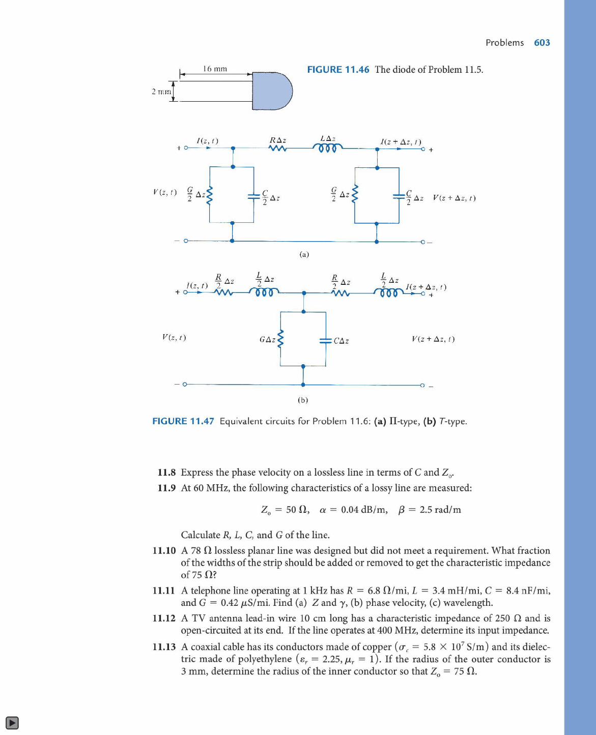
11.5 The copper leads of a diode are 16 mm in length and have a radius of 0.3 mm. They are separated by a distance of 2 mm as shown in Figure 11.46. Find the capacitance between the leads and the ac resistance at 10 MHz.
Section 11.3-Transmission Line Equations
*I 1.6 In Section 11.3, it was mentioned that the equivalent circuit of Figure 11.5 is not the only possible one. Show that eqs. (11.4) and ( 11.6) would remain the same if the II-type and T-type equivalent circuits shown in Figure 11.47 were used.
11.7 (a) Show that at high frequencies (R << wL, G << wL),
y = GJf + ~~) + jwVLC
(b) Obtain a similar formula for Z0
•
16mm
l (z, t)
V (z, t) G 2 ~z
V(z, t)
R6.z
c -Az 2
L -Az 2
GAz
FIGURE 11.46 The diode of Problem 11.5.
(a)
(b)
L6.2
G - /j,z 2
C;j,z
l(z +Liz, t)
L -Az 2
+
c -Az V(z+Az,t) 2
V(z + Az, t)
FIGURE 11.47 Equivalent circuits for Problem 11.6: (a) II-type, (b) T-type.
11.8 Express the phase velocity on a lossless line in terms of C and Z0 •
11.9 At 60 MHz, the following characteristics of a lossy line are measured:
Z0 = 50 0, a = 0.04 dB/m, f3 = 2.5 rad/m
Calculate R, L, C, and G of the line.
Problems 603
11.10 A 78 0 lossless planar line was designed but did not meet a requirement. What fraction of the widths of the strip should be added or removed to get the characteristic impedance of 75 fl?
11.11 A telephone line operating at 1 kHz has R = 6.8 fl/mi, L = 3.4 mH/mi, C = 8.4 nF/mi, and G = 0.42 µ,Simi. Find (a) Zand -y, (b) phase velocity, (c) wavelength.
11.12 A TV antenna lead-in wire 10 cm long has a characteristic impedance of 250 0 and is open -circuited at its end. If the line operates at 400 MHz, determine its input impedance.
11.13 A coaxial cable has its conductors made of copper (ere = 5.8 X 10⁷ Sim) and its dielectric made of polyethylene ( sr = 2.25, µr = 1). If the radius of the outer conductor is 3 mm, determine the radius of the inner conductor so that zo = 75 fl.
604 CHAPTER 11 TRANSMISSION LINES
11.14 For a lossless two-wire transmission line, show that 1
(a) The phase velocity u = c = .. ITr. vLC
120 d (b) The characteristic impedance Z
0 = .. r- cosh - I -
Ver 2a
Is part (a) true of other lossless lines?
11.15 A twisted line, which may be approximated by a two-wire line, is very useful in the telephone industry. Consider a line comprising two copper wires of diameter 0.12 cm that have a 0.32 cm center-to-center spacing. If the wires are separated by a dielectric material with e = 3.5e0 , find L, C, and Z 0 •
11.16 A distortionless cable is 4 m long and has a characteristic impedance of 60 0. An attenuation of 0.24 dB is observed at the receiving end. Also, a signal applied to the cable is delayed by 80 µs before is measured at the receiving end. Find R, G, L, and C for the cable.
11.17 A distortionless line operating at 120 MHz has R = 20 Olm, L = 0.3 JLHlm, and C = 63 pF Im. (a) Determine y, u, and Z0 • (b) How far will a voltage wave travel before it is reduced to 20% of its initial magnitude? ( c) How far will it travel to suffer a 45° phase shift?
11.18 On a distortionless line, the voltage wave is given by
V( f') = 120e0·0025e' cos(l08t + 2e 1
) + 60e-0·0025f' cos(108t - 2e1
)
where e' is the distance from the load. If Zi = 300 !l, find (a) a, f3, and u, (b) Z0 and J( e '). 11.19 The voltage on a line is given by
V( e) = 80e10-
3
e cos(21T X 104 t + O.Olf) + 60e- 10- u cos(21T X 104 t + O.Olf) V
where e is the distance from the load. Calculate y and u.
11.20 A distortionless transmission line satisfies RC = LG. If the line has R = 10 mOlm, C = 82 pFlm, and L = 0.6 JLHlm, calculate its characteristic impedance and propagation constant. Assume that the line operates at 80 MHz.
11.21 A coaxial line 5.6 m long has distributed parameters R = 6.5 Olm, L = 3.4 µ,Him, G = 8.4 mSlm, and C = 21.5 pFlm. If the line operates at 2 MHz, calculate the characteristic impedance and the end-to-end propagation time delay.
11.22 A lossy transmission line of length 2.1 m has characteristic impedance of 80 + )60 il. When the line is short-circuited, the input impedance is 30 - j12 il. (a) Determine a and {3. (b) Find the input impedance when the short circuit is replaced by Zi = 40 + j30 0.
11.23 A lossy transmission line with characteristic impedance of 7 5 + j60 !l is connected to a 200 0 load. If attenuation is 1.4 Nplm and phase constant is 2.6 radlm, find the input impedance for € = 0.5 m.
Section 11.4-lnput Impedance, Standing Wave Ratio, and Power
11.24 (a) Show that a transmission coefficient may be defined as
Vi 2Zi ri = v+ = I + ri =
o Zi + Zo
Problems 605
(b) Find Ti when the line is terminated by (i) a load whose value is nZ0 , (ii) an open circuit, (iii) a short circuit, (iv) Zi = Z0 (matched line).
11.25 A lossy transmission line has R = 3.5 !1./m, L = 2 µ,Him, C = 120 pF/m, and G = 0. At 400 MHz, determine a, {3, Z0 , and u.
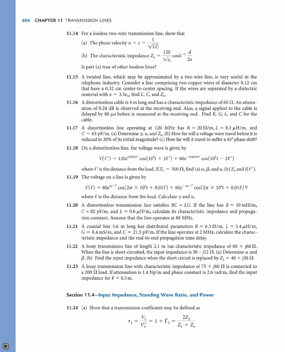
11.26 Find the input impedance of a short-circuited coaxial transmission line of Figure 11.48 if Z0 = 65 + j38 !l, y = 0.7 + j2.5/m, e = 0.8 m.
11.27 A 50 Q, transmission line of length e is open-circuited. If the input impedance is - j62 0, determine e in terms of A.
11.28 Refer to the lossless transmission line shown in Figure 11.49. (a) Find f and s. (b) Determine Zin at the generator.
11.29 A 60 fl. lossless line is connected to a source with Vg = 10L0° Vrms and Zg = 50 -j40 n and terminated with a load of j40 n.. If the line is 100 m long and f3 = 0.25 rad/m, calculate Zin and V at (a) The sending end ( c) 4 m from the load
(b) The receiving end ( d) 3 m from the source
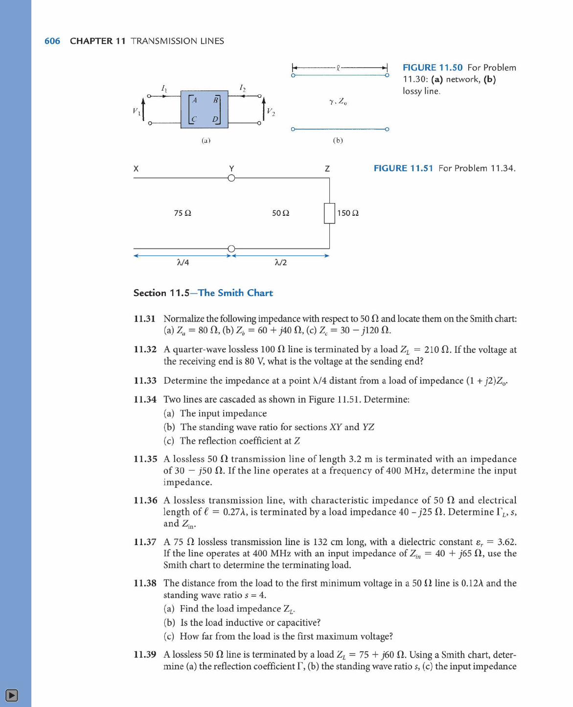
*11.30 Consider the two-port network shown in Figure 1 l.50(a). The relation between the input and output variables can be written in matrix form as
l -.
For the lossy line in Figure 11.SO(b ), show that the ABCD matrix is
')J6
co sh '}' e zo sinh 1' e ~ sinh yf cosh yf
0
-.
FIGURE 11.48 For Problem 11.26.
Zo=50Q 1200
FIGURE 11.49 For Problem 11.28.
606 CHAPTER 11 TRANSMISSION LINES
(a)
x y
75Q son
1../4 'A/2
(b)
z
1son
FIGURE 11.50 For Problem 11.30: (a) network, (b) lossy line.
FIGURE 11.51 For Problem 11.34.
Section 11.5- The Smith Chart
11.31 Normalize the following impedance with respect to 50 fl. and locate them on the Smith chart: (a) za = 80 n, (b) zb = 60 + j40 n, (c) zc = 30 - j120 n.
11.32 A quarter-wave lossless 100 fl. line is terminated by a load Zr = 210 fl.. If the voltage at the receiving end is 80 V, what is the voltage at the sending end?
11.33 Determine the impedance at a point A./4 distant from a load of impedance (1 + j2)Z0 •
11.34 Two lines are cascaded as shown in Figure 11.51. Determine:
(a) The input impedance
(b) The standing wave ratio for sections XY and YZ
(c) The reflection coefficient at Z
11.35 A lossless 50 fl. transmission line of length 3.2 m is terminated with an impedance of 30 - j50 fl.. If the line operates at a frequency of 400 MHz, determine the input impedance.
11.36 A lossless transmission line, with characteristic impedance of 50 0 and electrical length of e = 0.27 A, is terminated by a load impedance 40 - j25 a. Determine f'v S,
and Zin·
11.37 A 75 0 lossless transmission line is 132 cm long, with a dielectric constant er = 3.62. If the line operates at 400 MHz with an input impedance of Z;n = 40 + j65 fl., use the Smith chart to determine the terminating load.
11.38 The distance from the load to the first minimum voltage in a 50 !l line is 0.12A and the standing wave ratio s = 4.
(a) Find the load impedance Zr.
(b) Is the load inductive or capacitive?
(c) How far from the load is the first maximum voltage?
11.39 A lossless 50 fl. line is terminated by a load 21 = 75 + j60 0. Using a Smith chart, determine (a) the reflection coefficient r, (b) the standing wave ratios, (c) the input impedance
Problems 607
at 0.2'A. from the load, (d) the location of the first minimum voltage from the load, (e) the shortest distance from the load at which the input impedance is purely resistive.
11.40 A transmission line is terminated by a load with admittance Yi = ( 0.6 + j0.8) I Z0 • Find the normalized input impedance at 'A./6 from the load.
11.41 Using the Smith chart, determine the admittance of Z = 100 + j60 !l with respect to zo = 50 n.
11.42 A 50 il transmission line operates at 160 MHz and is terminated by a load of 50 + j30 fl.. If its wave speed is c/2 and the input impedance is to be made real, calculate the minimum possible length of the line and the corresponding input impedance.
11.43 A 50 n coaxial cable is 'A./ 4 long and is terminated by a load 40 - j30 fl.. Use the Smith chart to find the input admittance Yin.
11.44 (a) Calculate the reflection coefficient corresponding to Zr = (0.5 - j)Z0 •
(b) Determine the load impedance corresponding to the reflection coefficient 0.4 !_25°.
11.45 An 80 fl. transmission line operating at 12 MHz is terminated by a load Zi. At 22 m from the load, the input impedance is 100 - j120 fl.. If u = 0.8c,
(a) Calculate f v Zin, max' and Zin, min·
(b) Find Zv s, and the input impedance at 28 m from the load. ( c) How many Zin, max and Z in, min are there between the load and the 100 - jl 20 fl. input
impedance?
11.46 An antenna, connected to a 150 n lossless line, produces a standing wave ratio of 2.6. If measurements indicate that voltage maxima are 120 cm apart and that the last maximum is 40 cm from the antenna, calculate (a) The operating frequency (b) The antenna impedance (c) The reflection coefficient (assume that u = c).
11.47 An 80 fl lossless line has ZL = j60 n and Zin = }40 n. (a) Determine the shortest length of the line. (b) Calculate s and r L·
11.48 A 50 il air-filled line is terminated in a mismatched load of 40 + j25 !l. Find the shortest distance from the load at which the voltage has the smallest magnitude.
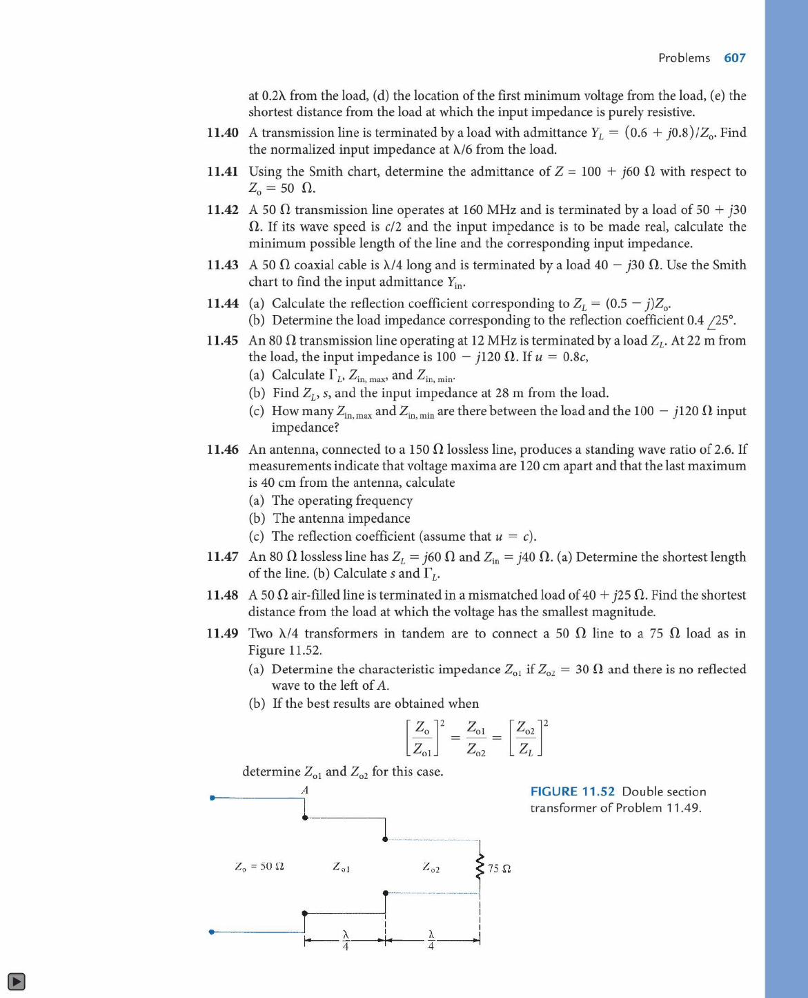
11.49 Two 'A./4 transformers in tandem are to connect a 50 0, line to a 75 fl. load as in Figure 11.52.
•
•
(a) Determine the characteristic impedance Z01 if Z02 = 30 n. and there is no reflected wave to the left of A.
(b) If the best results are obtained when
determine Z01 and Z02 for this case. A
Z0 = 50 fl
FIGURE 11.52 Double section transformer of Problem 11.49.
608 CHAPTER 11 TRANSMISSION LINES
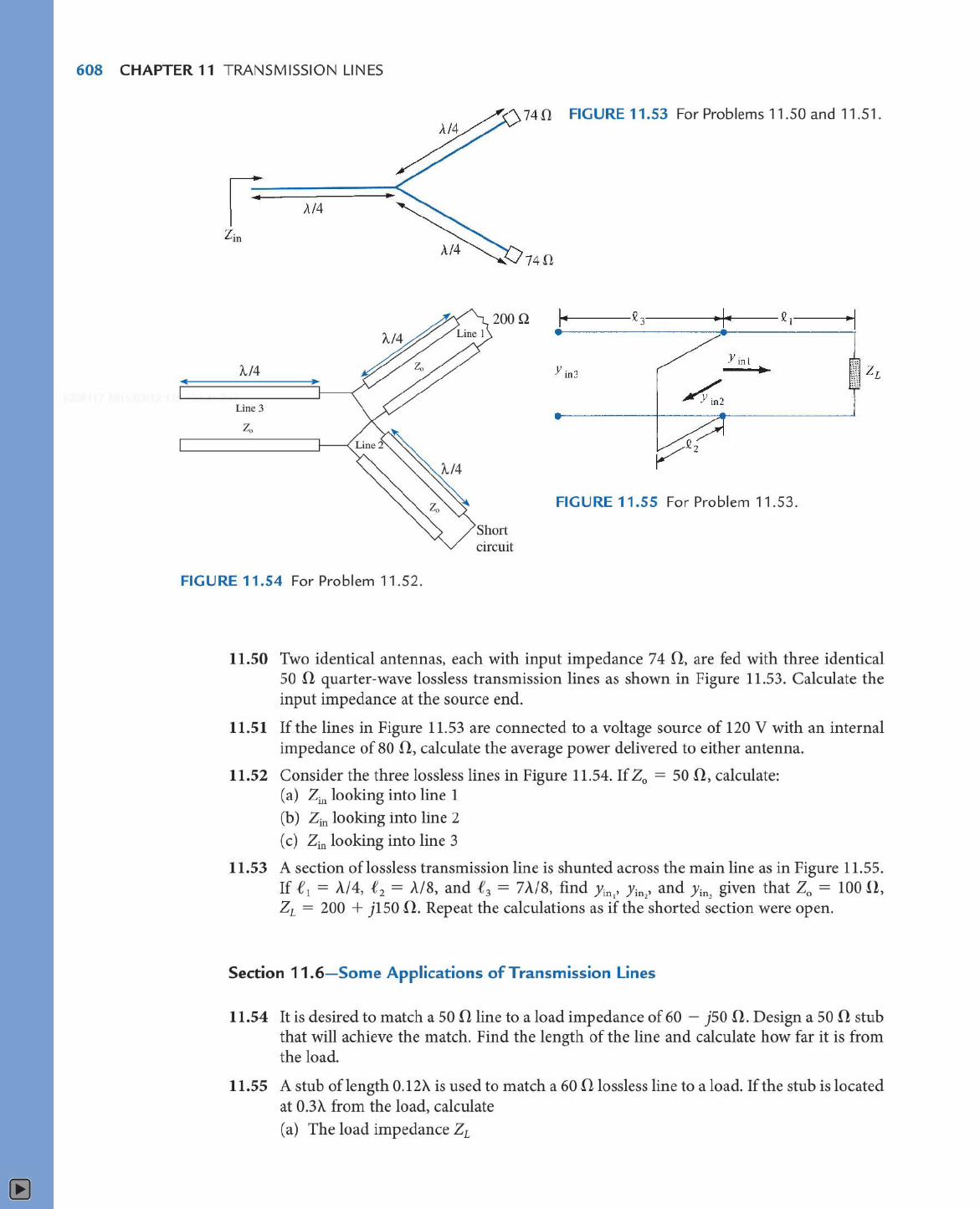
74 !1 FIGURE 11.53 For Problems 11.50 and 11.51.
/../4
74!1
2000
'A./4
Line3
FIGURE 11.55 For Problem 11.53.
circuit
FIGURE 11.54 For Problem 11.52.
11.50 Two identical antennas, each with input impedance 7 4 fl, are fed with three identical 50 !l quarter-wave lossless transmission lines as shown in Figure 11.53. Calculate the input impedance at the source end.
11.51 If the lines in Figure 11.53 are connected to a voltage source of 120 V with an internal impedance of 80 !l, calculate the average power delivered to either antenna.
11.52 Consider the three lossless lines in Figure 11.54. If Z0 = 50 !l, calculate: (a) Zin looking into line 1 (b) Zin looking into line 2 ( c) Zin looking into line 3
11.53 A section of lossless transmission line is shunted across the main line as in Figure 11.55. If f 1 = A/4, ! 2 = A/8, and ! 3 = 7 A/8, find Yin,• Ji
0 2, and Yin
3 given that Z0 = 100 !l,
Zr = 200 + jl 50 !l. Repeat the calculations as if the shorted section were open.
Section 11.6-Some Applications of Transmission Lines
11.54 It is desired to match a 50 !l line to a load impedance of 60 - j50 !l. Design a 50 !l stub that will achieve the match. Find the length of the line and calculate how far it is from the load.
11.55 A stub of length 0.12A is used to match a 60 fl lossless line to a load. If the stub is located at 0.3A from the load, calculate
(a) The load impedance Zr
Problems 609
(b) The length of an alternative stub and its location with respect to the load ( c) The standing wave ratio between the stub and the load
11.56 A 50 fi lossless transmission line that is 20 m long is terminated into a 120 + j220 fi load. To perfectly match, what should be the length and location of a short-circuited stub line? Assume an operating frequency of 1 O MHz.
11.57 On a lossless line, measurements indicates = 4.2 with the first maximum voltage at A./4 from the load. Determine how far from the load a short-circuited stub should be located and calculate its length.
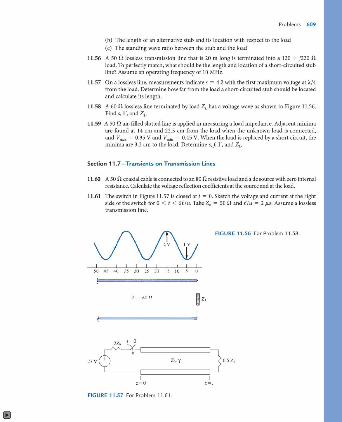
11.58 A 60 fi lossless line terminated by load 21 has a voltage wave as shown in Figure 11.56. Find s, f, and Zr.
11.59 A 50 n air-filled slotted line is applied in measuring a load impedance. Adjacent minima are found at 14 cm and 22.5 cm from the load when the unknown load is connected, and Vmax = 0.95 V and Vmin = 0.45 V. When the load is replaced by a short circuit, the minima are 3.2 cm to the load. Determine s,j, f, and Z1.
Section 11.7-Transients on Transmission Lines
11.60 A 50 0 coaxial cable is connected to an 80 0 resistive load and a de source with zero internal resistance. Calculate the voltage reflection coefficients at the source and at the load.
11.61 The switch in Figure 11.57 is closed at t = 0. Sketch the voltage and current at the right side of the switch for 0 < t < 6C I u. Take Z0 = 50 fi and f I u = 2 µ.,s. Assume a lossless transmission line.
FIGURE 11.56 For Problem 11.58.
I I I I I 5U 45 40 35 30 25 20 15 10 5 ()
' . \..
' n \
27V Zo, y 0.5Zo
I z =O z =,
FIGURE 11.57 For Problem 11.61.
610 CHAPTER 11 TRANSMISSION LINES
v + g --
Is 1omAL1
0
FIGURE 11.58 For Problem 11 _62.
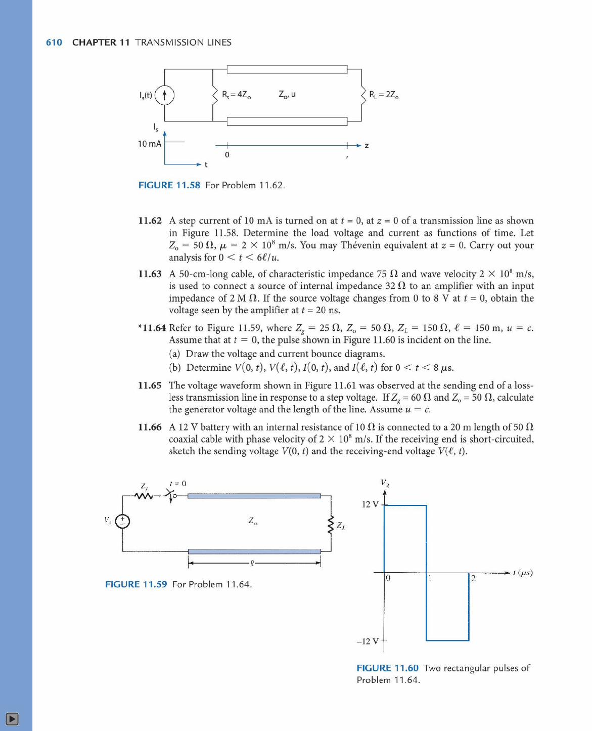
11.62 A step current of 10 mA is turned on at t = 0, at z = 0 of a transmission line as shown in Figure 11.58. Determine the load voltage and current as functions of time. Let Z0 = 50 !l, µ = 2 X 10⁸ m/s. You may Thevenin equivalent at z = 0. Carry out your analysis for 0 < t < 6f I u.
11.63 A SO-cm-long cable, of characteristic impedance 75 n and wave velocity 2 X 10⁸ mis, is used to connect a source of internal impedance 32 n to an amplifier with an input impedance of 2 M a. If the source voltage changes from 0 to 8 V at t = 0, obtain the voltage seen by the amplifier at t = 20 ns.
*11.64 Refer to Figure 11.59, where Zg = 25 0, Z0 = 50 !1, Zr = 150 D, f = 150 m, u = c. Assume that at t = 0, the pulse shown in Figure 11.60 is incident on the line. (a) Draw the voltage and current bounce diagrams. (b) Determine V( 0, t), V( t1, t), I( 0, t), and I( e, t) for 0 < t < 8 µs.
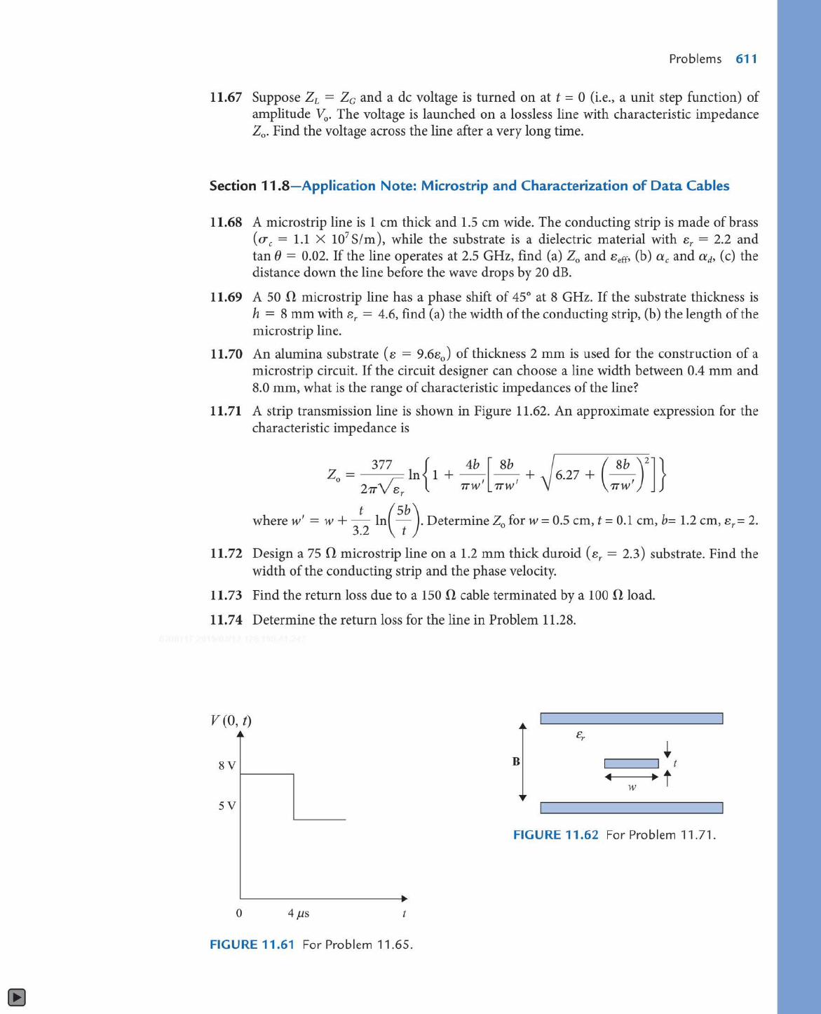
11.65 The voltage waveform shown in Figure 11.61 was observed at the sending end of a lossless transmission line in response to a step voltage. If Zg = 60 n and Z0 = 50 .fl, calculate the generator voltage and the length of the line. Assume u = c.
11.66 A 12 V battery with an internal resistance of 10 .fl is connected to a 20 m length of 50 n coaxial cable with phase velocity of 2 X 10⁸ m/ s. If the receiving end is short-circuited, sketch the sending voltage V(O, t) and the receiving-end voltage V( .e, t).
' 12y _,__ __ _
FIGURE 11.59 For Problem 11.64. --t-o-----!1------..-2----- / (µs)
-12 v--
FIGURE 11.60 Two rectangular pulses of Problem 11.64.
Problems 611
11.67 Suppose Zi = Zc and a de voltage is turned on at t = 0 (i.e., a unit step function) of amplitude V0 • The voltage is launched on a lossless line with characteristic impedance Z0 • Find the voltage across the line after a very long time.
Section 11.8-Application Note: Microstrip and Characterization of Data Cables
11.68 A microstrip line is 1 cm thick and 1.5 cm wide. The conducting strip is made of brass (uc = 1.1 X 10⁷ S/m), while the substrate is a dielectric material with er = 2.2 and tan(} = 0.02. If the line operates at 2.5 GHz, find (a) Z0 and Beff> (b) ac and a a, (c) the distance down the line before the wave drops by 20 dB.
11.69 A 50 il microstrip line has a phase shift of 45° at 8 GHz. If the substrate thickness is h = 8 mm with er = 4.6, find (a) the width of the conducting strip, (b) the length of the microstrip line.
11.70 An alumina substrate (e = 9.6e0 ) of thickness 2 mm is used for the construction of a microstrip circuit. If the circuit designer can choose a line width between 0.4 mm and 8.0 mm, what is the range of characteristic impedances of the line?
11. 71 A strip transmission line is shown in Figure 11.62. An approximate expression for the characteristic impedance is
377 { 4b [ Sb ~ ( 8b )2
] } Z 0 = Ve,, ln 1 + --, --, +6.27 + --, 211" e 1T"W 1T"W 1TW
r
where w' = w + _t_ ln(Sb). Determine Z0
for w = 0.5 cm, t = 0.1 cm, b= 1.2 cm, sr= 2. 3.2 t
11.72 Design a 75 0 microstrip line on a 1.2 mm thick duroid (er= 2.3) substrate. Find the width of the conducting strip and the phase velocity.
11.73 Find the return loss due to a 150 il cable terminated by a 100 il load.
11.74 Determine the return loss for the line in Problem 11.28.
v (0, t) ~~
8V
5V
.. 0 4µs t
FIGURE 11.61 For Problem 11.65.
B + ..... , ------., t
.-..i---. t w
FIGURE 11.62 For Problem 11.71 .