Embed Size (px)
Citation preview
SOLAR HEATING OF BUILDINGS AND DOMESTIC HOT WATER. REVISION.(U)NAY 80 E R DURLAK
UNCLASSIFIED CEL-TR-877 NL
MN mmmmhmmmmuUII
111.11
112.
MICROCOPY RESOLUTION TEST CHART
NATIONAL tBUF~fAU (O STANDARDFS 1%j A
0to
000
Technical Report 8-77Thus 'itilluikd.
Edward R. Durlak~ Civil Engnering Laboratory
SNaval Construction Battalion CenterSPort Hueneme, California 93043
Naval Facilities EngineeringCom1mand ~8AppriC tor P11111 lth w 11"18 0 2 8
FOREWORD
Conversion to solar heating at Naval facilities, where costeffective, could have a significant impact on dollar and fuel savings.The amount of available sun, the cost of equipment, the cost ofavailable fossil fuels, and building heating loads must be considered byfacility engineers in designing cost-effective solar heating systems.This document presents guidelines for engineers to make preliminarydesign and cost analyses and to prepare specifications for bidders onsolar systems.
We are working with NAVFAC towards the development of a designmanual for utilization of solar energy. This document, a revision ofCEL TR 835, represents a long step in that direction. An importantfeature of this report is the use of worksheets for stepwise calculationof total installation costs, solar collector parameters, domestic hot waterdemand, monthly solar radiation yields, cost avoidance for fossil fuel,and other costs associated with solar heating installations. Thisrevision has incorporated some additional information on cooling withsolar energy and passive solar construction.
Recommendations or modifications to this manual based onexperience in using it should be submitted to: Code LOMAE, CivilEngineering Laboratory, Naval Construction Battalion Center, PortHueneme, CA 93043.
R.OPOCaptain, CEC, USNOfficer in ChargeCivil Engineering Laboratory
[DD 1473 at end of report]I
_ K ,-
CONTENTS
Page
1. 0 INTRODUCTION .. .. ...... ...... ...........
1.1 Scope .. .... ....... ....... ....... 11.2 Related Criteria .. .... ....... .......... 11.3 Solar Energy .. .. ...... ....... ....... 4
1.3.1 Solar Radiation .. .... ....... ...... 41.3.2 Collecting Solar Energy. .. ..... ....... 61.3.3 Solar Collector Orientation. .. .. .......... 71.3.4 Advantages and Disadvantages. ... ....... 8
2.0 SOLAR SYSTEM COMPONENTS .. .. ..... .......... 92.1 Collectors. .. ....... ...... .......... 9
2.1.1 Liquid and Air-Type Collectors .. .... ..... 132.1.2 Selective Surfaces. .. ... ....... ..... 132.1.3 Collector Covers (Glazes). .. ..... ...... 152.1.4 Collector Insulation .. ... ....... ..... 212.1.5 Collector Housings. ... ....... ...... 212.1.6 Collector Gaskets and Sealants. ... ....... 222.1.7 Collector Fluids - Corrosion and Freeze
Protection .. .. ...... ...... ...... 232.1.7.1 Silicone Fluids. .. ..... ....... 282.1.7.2 Hydrocarbons. .. ....... ..... 292.1.7.3 Distilled Water .. .. ....... ... 322.1.7.4 Water/Antifreeze. .. ..... ...... 32
2.1.8 Collector Connections .. ... ....... ... 332.1.9 Collector Efficiency and Heat Losses .. .. ..... 352.1.10 Other Types of Solar Collectors. .. ....... 42
2.1.10.1 Evacuated-Tube Collectors. .. ..... 422.1.10.2 Concentrating Collectors .. .. ..... 42
2.2 Energy Storage and Auxiliary Heat. .. ... ....... 44
2.2.1 Storage Tanks .. ..... ....... ..... 492.3 Domestic Hot Water Systems (DHW). .. .... ...... 502.4 Thermosyphon Systems. .. .... ...... ...... 512.5 Space Heating and DHW Systems. .. ..... ...... 51
2.5.1 Heat Distribution for Liquid-Type SolarSystems. .. ... ....... ...... .... 60
2.5.2 Heat Distribution for Air-Type SolarSystems .. .. ..... ....... ....... 62
2.5.3 Heat Pumps .. .. ...... ....... ... 62
2.6 Passive Systems. .. ...... ...... ....... 66
Page
2.7 Solar Cooling Systems ..... ................. ... 75
2.7.1 Absorption Cooling ...... ............... 752.7.2 Rankine Cycle Heat Engine Cooling ........ ... 782.7.3 Desiccant Cooling ....... ................ 792.7.4 Other Cooling Methods ...... ............. 802.7.5 Estimating System Size .... ............. ... 82
2.8 System Controls ...... .................... ... 832.9 Piping, Pumps, Valves ..... ................. ... 86
2.9.1 Pipe and Header Sizing ...... ............. 862.9.2 Pumps and Collector Flowrate .... .......... 862.9.3 Valves ...... ..................... ... 87
2.10 Other Considerations .... ................. .... 88
2. 10.1 Architectural ....... .................. 882.10.2 Reduction of Heat Losses ............... ... 882.10.3 Maintenance and Accessibility ............ .... 89
3.0 DESIGN METHODS ...... ...................... ... 89
3.1 Job Summary - Worksheet A ...... .............. 913.2 Solar Collector Parameters - Worksheet B ........ ... 913.3 Load Calculations - Worksheet C-i .............. ... 943.4 Demand Calculations - DHW - Worksheet C-2 ......... 1013.5 Monthly Solar Collection Parameters -
Worksheet D-1 ......................... 1013.6 Fraction of Load Supplied by Solar Heat -
Worksheet D-2 ...... ..................... .. 1083.7 Fuel Savings - Worksheets E-1 and E-2 .......... .110
3.7.1 Present Worth Using A Discount Factor andFuel Differential Escalation Rates .... ........ 111
3.7.2 Present Worth Using Fuel Escalation RatesWithout the Discount Factor ............. . .111
3.8 Collector Temperatures - Worksheet E-1 .......... ... 1133.9 Solar System Cost - Worksheet F ..... ............ 1153.10 Additional Costs - Worksheet G ... ............ .. 1173.11 Sizing the Heat Exchanger for Space Heating ....... 1173.12 Air-Heating Collector Design - Worksheet H ......... 1173.13 Worksheets ....... ...................... .. 120
FWorksheet A - Job Summary .... ............. ... 121Worksheet B - Solar Collector Parameters ... ....... 122
BM, ' S E Worksheet C-i - Load Calculations ..... .......... 123wC ri Worksheet C-2 - Demand Calculations -tmotuae4d Domestic Water Heater ...... .............. 124Jsttivaati n.Worksheet D-1 - Monthly Solar Collection
Parameters ...... .................... 1253Worksheet D-2 - Fraction of Load Supplied
Jug r1utl_..L by Solar Heat ....... ................... 126
0,1 1 1Avatl st,/or
Dist ep"Clal lv- _
Page
Worksheet E-1 - Value of Fuel Saved .......... .. 127Worksheet E-2 - Present Worth Analysis ... ....... 128Worksheet F - Solar System Cost Analysis ... ...... 129Worksheet G - Additional Cost Items Related
to Use of Solar Heating ..... .............. 130Worksheet H - Solar Air Collector System
Design Summary .... ................. .. 131
4.0 EXAMPLE PROBLEMS ....... .................... 1324.1 Discussion of Example 1, Space Heating
and DHW System ..... .................... .. 1324.1.1 Example 1 - Worksheets .... ............. 135
5.0 DIRECTORY OF SOLAR EQUIPMENT MANUFACTURERS . . . 145
5.1 Manufacturers Directories ..... ............... 1455.2 Manufacturers of Flat Plate Collectors and Other
Solar Hot Water Equipment ..... ................ 145
6.0 REFERENCES (0) AND SELECT BIBLIOGRAPHY ... ...... 153
7.0 LIST OF SYMBOLS ....... ..................... 163
LIST OF FIGURES
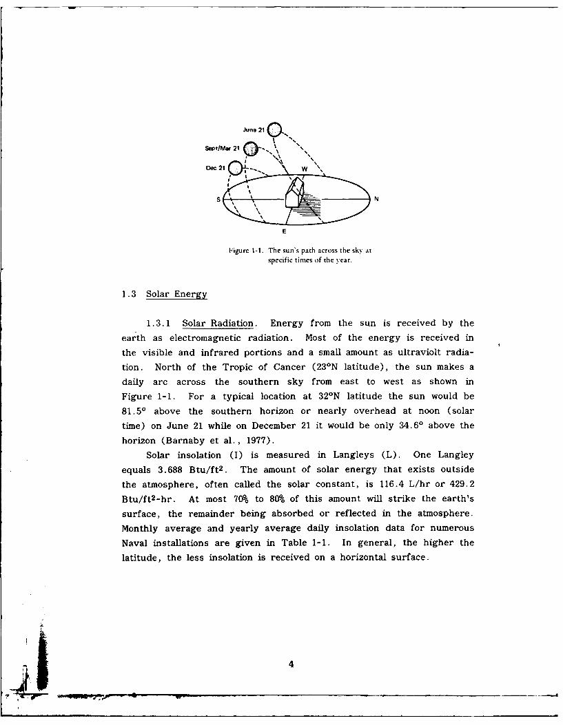
Figure 1-1. The sun's path across the sky at specifictimes of the year ...... .................. 4
Figure 1-2. Schematic cross section of typical solar heatcollector with heavy back insulation and twocover sheets ....... .................... 6
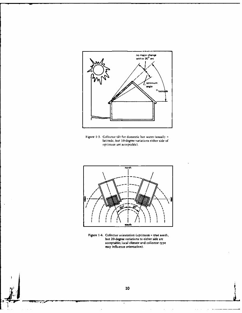
Figure 1-3. Collector tilt for domestic hot water (usually =latitude, but 10-degree variations either sideof optimum are acceptable). ............. 10
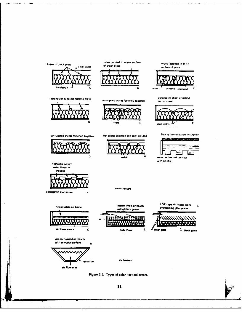
Figure 1-4. Collector orientation (optimum = true south, but20-degree variations to either side are acceptable;local climate and collector type may influenceorientation) ....... ..................... 10
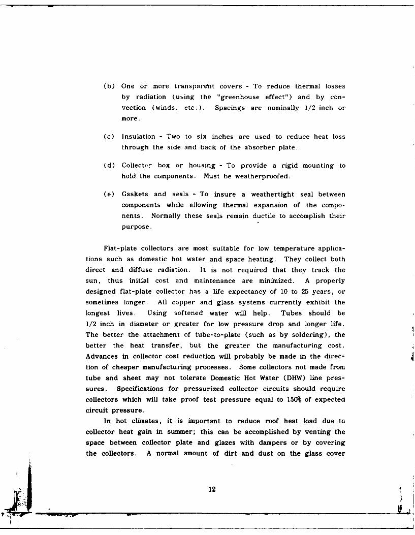
Figure 2-1. Types of solar heat collectors. ............ 11Figure 2-2. Single gasket seal for double glazing ........... 23Figure 2-3. Typical sealing method for single or
double glazing .... ................... ... 23Figure 2-4. Typical configurations for solar water
heater systems ...... ................... 25Figure 2-5. Heat exchangers for solar water heating systems. 26Figure 2-6. Connection schemes for solar heating systems. .. 35Pigure 2-7. Typical solar heater collector efficiencies ......... 37Figure 2-8. Evacuated tube solar heat collector ............ 47Figure 2-9. Concentrating collectors for solar energy ......... 48
v
Page
Figure 2-10. Schematic of potable hot water heating systemusing solar storage (tempering) tank ahead ofconventional fueled or electric serviee waterheater ........ ....................... 51
Figure 2-11. Typical DHW installation ...... ............. 55Figure 2-12. Minimum heating system, showing relationship
of collector, storage, and room unit heater..... 60Figure 2-13. Space heating system with closed collector loop. 62Figure 2-14. Space heating and domestic hot water system. 62Figure 2-15. Typical air-type space heating system ........... 63Figure 2-16. A liquid-to-air heat delivery system ............. 65Figure 2-17. Series-connected, solar-assisted
heat pump system. .................. 69Figure 2-18. Parallel-connected, solar-assisted
heat pump system .... ................. ... 71Figure 2-19. Passive solar energy systems ................ 72Figure 2-20. New-construction (office) passive
solar energy system ....... ............... 75Figure 2-21. Vertical wall solar collector. ............. 75Figlire 2-22. South wall solar collector with combined storage. 76Figure 2-23. Retrofitted large rock bin storage .............. 77Figure 2-24. Schematic of lithium bromide
absorption cooler ...... .................. 80Figure 2-25. Schematic of solar desiccant cooling ............. 85Figure 2-26. Control system strategy ................... 88Figure 2-27. Control system for space and DHW heating. ..... 89Figure 3-1. Fraction of space heating/DHW
load supplied by solar energy(Beckman, Klein, and Duffie, 1977) ............. 94
Figure 3-2. Slope factor, S, for use on Worksheet D-1(average over one day) ................... 107
Figure 3-3. Correction curve for slope factor method ........ 113Figure 3-4. Fraction of space heating/DHW load
supplied by solar air heating system(after Klein, Beckman, and Duffie, 1977) ........ 122
LIST OF TABLES
Table 1-1. Average Solar Radiation Intensities, Langleys/Day(Horizontal Surface) ...... ................ 5
Table 2-1. Advantages and Disadvantages of Air andLiquid Heating Systems ..... ............... 14
Table 2-2. Characteristics of Absorber Coatings(U.S. Dept HUD, 1977) .... ............... 16
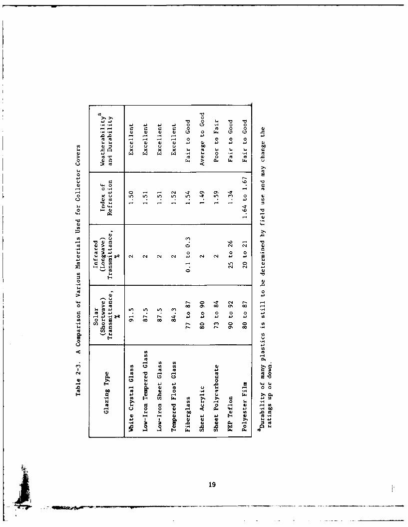
Table 2-3. A Comparison of Various Materials Usedfor Collector Covers ...... ................ 19
Table 2-4. Guide to Selection of Number of TransparentCover Plates ..................... 20
Table 2-5. Heat Transfer Fluids (Solar Engineering, 1978) . . 30
vi
Page
Table 2-6. Solar Collector Test Results .. .. ...... ..... 40Table 2-7. Advantages and Disadvantages of Tank
Types (Cole et al., 1979) .. .. ....... ..... 56Table 2-8. Storage Tank Costs. .. .... ....... ..... 58Table 2-9. Hot Water Demands and Use for Various
Types of Buildings .. .... ...... ....... 59Table 3-1. Building Heat Loss Rates..............99Table 3-2. Normal Total Heating Degree (Base 65"F) .. ... .. 100Table 3-3. DHW Temperature at Source in Selected
Locations (U.S. Dept HUD, 1977). .. ..... ... 106Table 3-4. Average Daytime Ambient Temperatures (*F)
(U.S. NOAA, 1968) .. .. ...................... 108Table 3-5a. Annual Fuel Inflation Factors , 10% Discount .. .. .. 116Table 3-5b. Fuel Inflation Factors - No Discount .. ..... .. 118Table 3-6. Solar System Component Cost Estimates .. ... ... 120Table 3-7. Solar Collector Prices. .. .... ....... ... 120
vii
1. 0 INTRODUCTION
This report presents design criteria and cost analysis methods forthe sizing and justification of solar heat collectors for potable waterheaters and space heaters. Sufficient information is presented toenable engineers to design solar space and water heating systems orconduct basic feasibility studies preparatory to design of large installa-tions. Both retrofit and new installations are considered. This reporthas been substantially revised from the previous edition (Beck andField, 1977). However, most of the revision is in Section 2.0, wheremore material of an exploratory nature has been added. Section 3. 0,which contains the calculation method and worksheets, is largely thesame, except that the economic analysis has been revised and newtables have been added to provide a self-contained source of meteorolog-ical data and collector test data. P revious users will have no trouble
using the worksheets of Section 3.0If information is desired on "how" to select, size, or orient a solar
system, this information will be found in Section 2.0. It is intendedthat this section be used as a reference in which the user may find
information on many topics relating to solar energy systems. Newsections include solar cooling, passive systems, collector fluids, andheat pumps. Other sections have been revised to include more informa-tion.
1.2 Related Criteria
Certain criteria relating to space heating and domestic hot water
I. (DHW) heating systems appear elsewhere and are listed below.
a. The Department of Defense general requirements are found in
the Construction Criteria Manual, DOD 4270.1-M.
b. Some portions of Design Manual DM-3 relating to heating and
hot-water systems pertain to this manual. These and other relevant
sources of applicable criteria are listed below:
Subject Source
Plumbing Systems Chapter 1Heating Systems Chapter 3Architectural Criteria Chapter 5Electrical Criteria Chapter 5Hazards & Safety Precautions Chapter 5Insulation Chapter 5Structural Criteria Chapter 5Central Heating Plant Chapter 8Corrosion Protection Chapter 9Water Conditioning Chapter 9Housing & Building Designs (definitive) NAVFAC P-272Weather Data NAVFAC P-89
c. Standards and performance criteria relating to solar heating
systems have been evolved by government agencies and various associa-
tions and institutes. The most widely used are listed below:
Subject Document
Solar Collector Instantaneous ASHRAE Standard 93-77, "MethodsPerformance of Testing to Determine the
Thermal Performance of SolarCollectors"
Thermal Storage Devices ASHRAE Standard 94-77, "Methodsof Testing Thermal StorageDevices Based on ThermalPerformance"
Complete Solar Collector National Bureau of Standards,Performance Evaluation NBSIR 78-1305A, "Provisional
Flat Plate Solar CollectorTesting Procedures: FirstRevision"
Testing Solar Hot Water ASHRAE Standard 95, "MethodsHeaters of Testing Solar Energy Pota-
ble Water Heaters"
2
Subject Document
Testing Swimming Pool Solar ASHRAE Standard 96, "MethodsCollectors of Testing to Determine the
Thermal Performance of LiquidSolar Collectors to Heating ofSwimming Pools"
Solar System Performance National Bureau of Standards,NBSIR 76-1187, "Interim Perfor-mance Criteria for Solar Heat-ing and Cooling Systems inCommercial Buildings"
Property Standards for Solar HUD Report 4930.2, "Inter-Systems mediate Minimum Property
Standards Supplement, SolarHeating and Domestic Hot WaterSystems"
Property Standards Developed National Bureau of Standards,for HUD Domestic Hot Water NBSIR 77-1272, "IntermediateInitiative Standards for Solar Domestic
Hot Water Systems/HUDInitiative"
Solar Collector Certification Standard 910, "The Air Condi-and Labeling tioning and Refrigeration
Institute (ARI) CertificationProgram for Solar Collectors"
Solar Collector Certification Solar Energy Industriesand Labeling Association, Standard PCS 1-79,
"S.E.I.A. Certified ThermalPerformance Rating Standardfor Solar Collectors"
Building Code (Second Draft, Council of American BuildingSeptember 1979) Officials, DOE/CS/4281-1, "Model
Document for Code Officials ofSolar Heating and Cooling of
Buildings"
Product Safety Standard (not National Bureau of Standards,completed) (See HUD report NBSIR 78-1143A, "Plan for the4930.2 for current safety Development and Implementationstandards.) of Standards for Solar Heating
and Cooling Applications"
In addition to these standards, there are installation standards
published by the Sheet Metal Air Conditioning Contractors' National
Association (SMACNA), plumbing standards published by The Interna-
tional Association of Mechanical and Plumbing Officials (IAMPO), and
various state building codes.
3
June 21
SeptlMar 21 0 -N. %,
Dec 21 W
S N
E
F'igure 1-1. The sun's path across the sky at
specific times of the year.
1.3 Solar Energy
1.3.1 Solar Radiation. Energy from the sun is received by the
earth as electromagnetic radiation. Most of the energy is received in
the visible and infrared portions and a small amount as ultraviolt radia-
tion. North of the Tropic of Cancer (23°N latitude), the sun makes a
daily arc across the southern sky from east to west as shown in
Figure 1-1. For a typical location at 321N latitude the sun would be
81.51 above the southern horizon or nearly overhead at noon (solar
time) on June 21 while on December 21 it would be only 34.60 above the
horizon (Barnaby et al., 1977).
Solar insolation (1) is measured in Langleys (L). One Langley
equals 3.688 Btu/ft 2 . The amount of solar energy that exists outside
the atmosphere, often called the solar constant, is 116.4 L/hr or 429.2
Btu/ft 2-hr. At most 70% to 80% of this amount will strike the earth's
surface, the remainder being absorbed or reflected in the atmosphere.
Monthly average and yearly average daily insolation data for numerous
Naval installations are given in Table 1-1. In general, the higher the
latitude, the less insolation is received on a horizontal surface.
4,e-
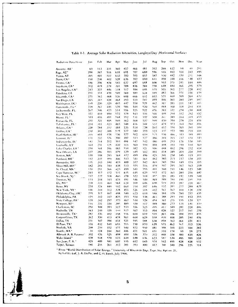
Table 1-1. Average Solar Radiation Intensities, Langleys/Day kHorizontal Surface)
Radi..mi DIata Fr m Jan Feb Mar Apr May Jun Jul Aug Sep Oct Nov Dee Year
Annette, AK' 63 113 231 360 457 466 481 352 266 122 59 41) 251
Page, AZ 294 367 516 618 695 707 680 596 516 402 310 243 49z6
Yurna, AZ 305 401 517 633 703 705 652 587 530 442 330 271 5016
Davis, CA 158 256 402 528 636 702 690 611 498 348 216 148 43 3
Fresno, CA' 186 296 438 545 637 697 668 606 503 375 241 160 446
Inyokern, CA* 312 419 578 7(11 789 836 784 738 648 484 366 295 579
Los Angeles, CA 243 337 446 318 517 594 645 579 505 365 277 228 442
Pasadena, CA 251 333 439 519 569 580 634 599 482 3(16 271 236 439)
Riverside, CA * 271 362 468 526 6(18 666 652 603 521 400 109 260 470
San Diego, CA 263 343 428 464 193 510 547 499 446 361 281 245 407
Washington, DC' 159 231 320 413 447 558 529 462 367 281 211 147 .31,
Gainesville. Fl ' 278 367 445 339 586 544 521 108 444 368 318 24 431
laeksouville, FL 267 346 423 514 556 525 522 476 383 331 274 231 41)4
Key West. FL 327 410 490 572 579 543 534 S0I 44S 394 332 292 452
Miami. FL ' 343 416 491 544 6r2 31 537 5(18 -147 381) 34 319 463,
Pensacola, FL 251 321 4115 51)9 362 568 537 S09 4301 394 278 224 416
T.alahassee, FL " 274 311 423 483 548 476 544 6.37 424 333 3114 260 .116
Atlta. GA 228 284 377 -184 535 554 338 5(12 412 35(0 265 201 391
(;riffin, GA 238 .302 388 519 577 681) 559 523 437 372 288 21(0 416
Pearl Harbor, HI 1,5 404 438 636 577 662 610 676 336 466, 393 '9 483
Lmont. IL' 171 232 326 390 .197 z53 327 486 384 265 157 1 1 .61
hldiauapis. IN 147 214 312 393 491 547 542 486 4(15 2', 176 131 646
Louisville. KY 16.4 231 325 421 515 661) 55(1 49)8 438 313 1901 15 ) 3,61)
Lake Charles, LA 23') 304 396 483 554 582 21 60, 448 4o2 296 ) 232 -114
New Orleans, LA 237 296 393 479 339 549 512 491 418 38) 269 220 3'9)
Bostml, MA' 139 198 293 364 472 499 496 425 341 238 145 119 31 1Portland, ME' 157 237 359 4(16 513 641 561 482 383 273 167 138 331
Annapolis. MI) 175 243 340 419 488 557 542 46') 383 294 18') 155 3r5Silver Hill, MI) 182 244 34(1 438 513 535 516 459 397 295 212 163 359
St. Cloud. MN (711 251 366 423 499 541 663 491 3,01 241 146 123 348
Cape Hatteras, NC 244 317 .1,2 671 635 645 629 ;57 472 .161 284 216 447
Sea Brook, NJ , 17 227 318 403 478 622 518 47 683 285 192 139 141
Trentln, NJ 173 244 343 424 491 64 341) 469 389 2'-1 1I9,5 IS5 35S
El . NV" 2.38 333 46,-4 664 624 718 6-18 608 619 313 287 221) 467
Ren,. NV 23.1 324 449 S02 664 714 7117 646 632 396 277 209 479
New York. NY 146 211) 312 378 455 526 518 492 361 262 160 128 324
()klaonma City, (6K" 266 317 417 418 "413 623 1,11) "h t84 379 284 237 435
Philadelphia, PA 175 242 3-17 425 493 554 538 4,S 388 293 191 152 353
State College, PA' 1.39 2112 297 373 467 5-14 528 464 361 275 155 1211 63'
Newport. RI *133 2.31 330 395 489 638 517 449 380 273 175 141 33-1,Charlesto, SC 251 31)8 393 517 53 556 523 495 417 349 281 228 4110
Nashville, TN 163 2411 329 1-,) 617 S67 553 494 428 327 217 161 370
Brownsville. TX ' 287 336 412 458 56 604 619 555 465 406 284 253 435
Corpus Crist,. TX 262 3311 413 474 661 604 629 558 471 408 285 241 436
Dallas, TX 231 307 394 454 621 595 588 538 458 363 261 221 411
El Paso, TX' 331 432 549 665 715 731 670 639 575 462 37 313 536
Norfolk, VA 2118 271 372 477 540 572 5I0 481 398 310 223 184 382
Seattle. WA 71 124 244 360 446 471 511 431 31(1 174 90 59 273
Albrook A. B. Panama' 392 476 525 499 4(14 336 371 372 448 338 380 420 426
Wake Island ' 438 518 570 623 644 648 636 623 687 530 485 399 558
San Juan, P. R. 429 489 581 61)7 555 612 643 674 542 495 428 428 532
Taipei, Taiwan 186 216 261 312 381 393 400 412 341 340 296 225 314
From "World Distribution lf Solar Energy." University of Wisetn sio Engr. Expr. Sta. Rpt no. 2 1,by G..G. Lof, J. A. Duffte. and C. 0. Smith, July 1966.
L5
protective, insulating insulation
transparent covers/of glass or plastic//..' fluid-carrying tubes
bonded to collector plate
// heat collector plate
tilt atiglte, wsuallv latitude pI~s 10-15"
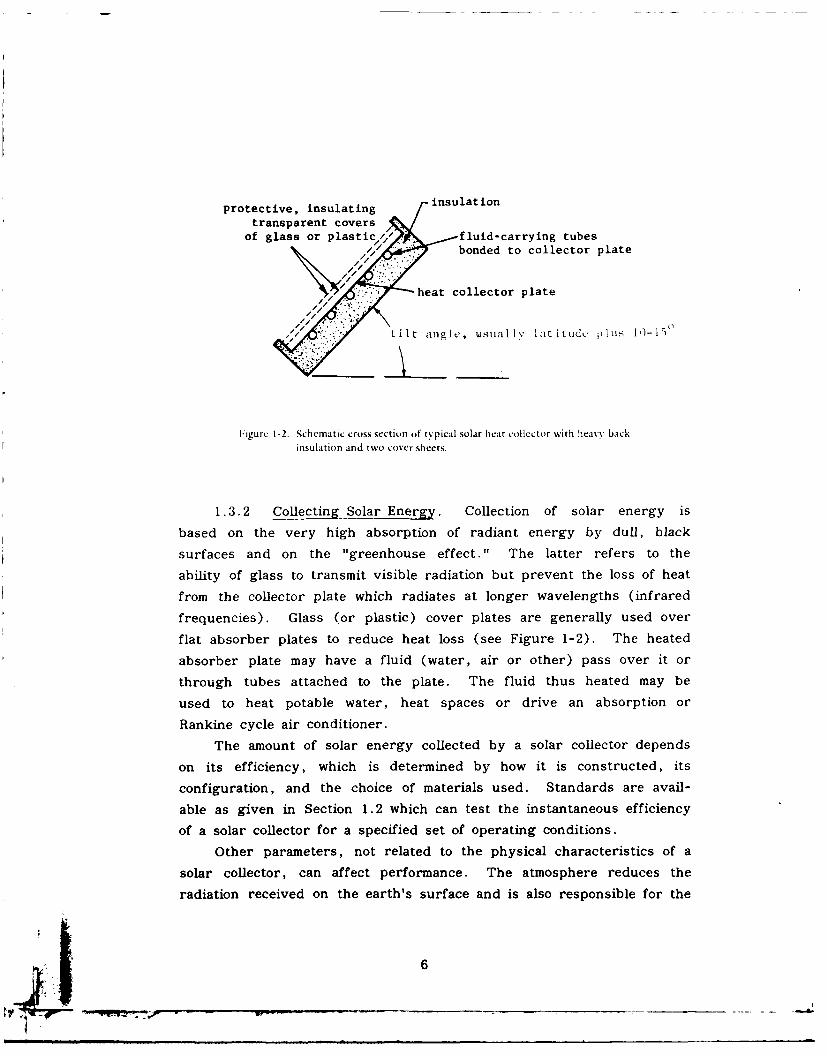
Figure 1-2. Schematic cross sectionl of typical solar heat Collector with heasv back
insulation and two cover sheets.
1 .3. 2 Collecting Solar Energy. Collection of solar energy is
based on the very high absorption of radiant energy by dull, black
surfaces and on the "greenhouse effect."0 The latter refers to the
ability of glass to transmit visible radiation but prevent the loss of heat
from the collector plate which radiates at longer wavelengths (infrared
frequencies). Glass (or plastic) cover plates are generally used over
flat absorber plates to reduce heat loss (see Figure 1-2). The heated
absorber plate may have a fluid (water, air or other) pass over it or
through tubes attached to the plate. The fluid thus heated may be
used to heat potable water, heat spaces or drive an absorption or
Rankine cycle air conditioner.
The amount of solar energy collected by a solar collector depends
on its efficiency, which is determined by how it is constructed, its
configuration, and the choice of materials used. Standards are avail-
able as given in Section 1 .2 which can test the instantaneous efficiency
of a solar collector for a specified set of operating conditions.
Other parameters, not related to the physical characteristics of a
solar collector, can affect performance. The atmosphere reduces the
radiation received on the earth's surface and is also responsible for the
6
scattering of light which results in diffuse, as distinct from direct.
solar radiation. The diffuse component may represent as much as
25-%-30%- of the total solar radiation depending on the weather conditions.
Solar flat plate collectors absorb heat from the diffuse component as
well as the direct. Thus, some heat is available on partly cloudy days.
The reflectance of the ground (snow, sand, water, etc.) or nearby
objects may also influence the amount of solar energy reaching a
collector. Therefore, the amount of solar energy received at any
location depends on the hour of the day, the day of the solar year,
and the meteorological conditions. This amount can vary from about 50
BtU/ft 2 -hr on a foggy winter day to as much as 300-375 Btu/ft2 -hr on
a typical sunny summer day.
1 .3.3 Solar Collector Orientation. Even though solar collectors
can collect heat from the diffuse component of solar radiation, solar
systems are designed to use the direct component. Direct radiation is
in the form of parallel rays coming straight from the sun. To best
capture this energy the solar collector should be tilted as shown in
Figure 1-2 so that it is more nearly perpendicular to the solar rays.
The "optimum" tilt angle varies even as the sun changes its position
throughout the day and year. However, since the solar system cannot
be continuously moved, some general rules can be stated:
1. For all year domestic hot water (DHW) heating use a tilt angle
equal to the latitude.
2. For all year DHW heating and winter space heating use a tilt
angle equal to the latitude plus 10-15 degrees.
3. For all year DHW heating, winter space heating, and summer
cooling use same as no. 1.
4. For winter only space heating use a tilt angle equal to the
latitude plus 10-15 degrees.
5. For summer only space cooling use a tilt angle equal to the
latitude minus 10-15 degrees.
7

6. For summer only space cooling and all year domestic hot water
heating use the same as no. 5.
In addition to choosing the best collector tilt angle, consideration
must be given to the orientation of a collector (i. e., the direction the
collector faces). Normally true south is the best and most frequent
choice. However, slightly west of south (10 degrees) may be prefer-
able in some locations if an early morning haze or fog is a regular
occurrence.
Some deviations from these tilt and orientation angles are allowable
without significantly affecting performance. As shown in Figures 1-3
and 1-4, the tilt angle may vary ±10 degrees and the orientation angle
up to 200 either side of true south (National Solar Heating and Cooling
Info Ctr, 1979). For these deviations the solar collectors would still
collect 95%- 100% of their rated capacity in most locations of the U .S.
Additional deviations would require more collector area to capture the
same amount of energy. As a very approximate rule of thumb, for each
deviation of 100 beyond that shown in Figures 1-3 and 1-4 add 10% more
collector area. If you must choose between an east roof and a west
roof, use the west roof in the western coastal area. Other areas will
require local weather considerations.
As important as collector location, is keeping the collectors out of
the shade, especially between 9 a.m. and 3 p.m., when most of the
useful energy collection occurs. In summary, although many buildings
will not have a "perfect" solar orientation, there can still be many
places with good solar energy potential.
1.3.4 Advantages and Disadvantages. Solar energy is inherently
nonpolluting, provides substantial freedom from the effects of fuel price
increases, and saves valuable fossil fuels. Disadvantages are that
collectors perform poorly in cold cloudy weather, when most needed;
and room heat exchangers and industrial unit heaters must be larger
than in conventional systems due to the relatively low temperature of
heating fluid. The disadvantages may be circumvented by good design;
8
where fuel costs are high enough (as discussed in the examples,Section 4), a solar system will prove cost effective. Solar systemsdesigned for combined heating and cooling will utilize the collectoryear-around and thus usually will be more cost effective.
2.0 SOLAR SYSTEM COMPONENTS
2. 1 Collectors
The collector is the most important and one of the most expensiveparts of a solar heating system. It must be long-lived and well insu-lated, yet its cost must be minimized. Collectors of primary interestfor space and water heating are of two basic types: liquid and air.Liquids may be water, an antifreeze mixture, or various hydrocarbon
and silicone heat transfer oils. Air-type collectors use air as thecollector fluid. The absorber plate is that part of the collector whichabsorbs the solar energy and converts it to thermal energy. A portionof the thermal energy is carried to the building or thermal storage unitby the fluid which circulates through passages in the absorber plate.
The absorber plates can be made of metal, plastic, or rubber com-pounds. The metals commonly used in order of decreasing thermalconductivity are copper, aluminum, and steel. Plastics (polyolefins)
and rubbers (ethylene propylene compounds) are relatively inexpensive,but due to their low thermal conductivity and their temperature limita-
tions, they are suitable only for low temperature applications, such asheating swimming pool water or for use with water source heat pumps.Typical cross sections of solar collector types are shown in Figure 2-1.
Other major components of a solar collector include:
(a) Absorber plate coating - To enhance the heat transfer andprotect the absorber plate.
9
no major changwithin 200 arco--x
optimuangle
Figure 1-3. Collector tilt for domestic hot water (usually =
latitude, but 10-degree variations either side ofoptimum are acceptable).
north
J;- -- c-'-/ / \ '
/ ' \, I , ,, ,I ,,111
south
Figure 1-4. Collector orientation (optimum = true south,but 20-degree variations to either side areacceptable; local climate and collector typemay influence orientation).
10*
Tue nbakpaetubes bonded to upper surf ace tubes fastened to lowerTube )wn bgakapat of black plate surface of plate
inationc v r l A wired Pse caped
rectnguar ube boned o patecorrugated sheet attachedre t %ua u e o d d t lt corrugated Plates fastened together to flat sheet
corrugated sheets fastened together flat plates-dimpled and spot welded Hay system-movable insulation
G wel ds H water in thermal contact Iwith ceiling
Thomason systemwater flIown in
troughs
water heaterscorrugated aluminum
finedplae ir eaermatrix-type air heater LOP-type air heater using N:fisieg black giruate overlapping glass platie
air flow arma K Side View L clear glass Lblack glass
vea-corrugated air heaterwith selective surface N
~ a t ion aIr heaters
air flow area
Figure 2-1. Types of solar heat collectors.
(b) One or more transparent covers - To reduce thermal losses
by radiation (using the "greenhouse effect") and by con-
vection (winds, etc.). Spacings are nominally 1/2 inch or
more.
(c) Insulation - Two to six inches are used to reduce heat loss
through the side and back of the absorber plate.
(d) Collector box or housing - To provide a rigid mounting to
hold the components. Must be weatherproofed.
(e) Gaskets and seals - To insure a weathertight seal between
components while allowing thermal expansion of the compo-
nents. Normally these seals remain ductile to accomplish their
purpose.
Flat-plate collectors are most suitable for low temperature applica-
tions such as domestic hot water and space heating. They collect both
direct and diffuse radiation. It is not required that they track the
sun, thus initial cost and maintenance are minimized. A properly
designed flat-plate collector has a life expectancy of 10 to 25 years, or
sometimes longer. All copper and glass systems currently exhibit the
longest lives. Using softened water will help. Tubes should be
1/2 inch in diameter or greater for low pressure drop and longer life.
The better the attachment of tube-to-plate (such as by soldering), the
better the heat transfer, but the greater the manufacturing cost.
Advances in collector cost reduction will probably be made in the direc-
tion of cheaper manufacturing processes. Some collectors not made from
tube and sheet may not tolerate Domestic Hot Water (DHW) line pres-
sures. Specifications for pressurized collector circuits should require
collectors which will take proof test pressure equal to 150% of expected
circuit pressure.
In hot climates, it is important to reduce roof heat load due to
collector heat gain in summer; this can be accomplished by venting the
space between collector plate and glazes with dampers or by covering
the collectors. A normal amount of dirt and dust on the glass cover
12
will reduce heat collected by about 5%. Normal rainfall is usually suffi-
cient to relieve this problem. Except for warm climates with high
insolation (1>400 L/day), two cover glasses may be optimum (see Section
2.1.3). In warm climates, one glass is optimum. Many plastics have an
undesirable transparency to infrared radiation, to which glass is nearly
opaque, so the desired "greenhouse effect" is not so pronounced with
plastic materials as with glass. However, losses by radiation from the
collector are small compared with convective losses due to wind; thus
plastics can be employed to reduce breakage and cost, but with some
loss in collector, performance. Plastics with maximum opaqueness to
infrared and maximum transparency to ultraviolet (UV) and visible
radiation and with high resistance to UV degradation should be speci-
fied. Collector orientation should follow the guidelines given in Section
1.3.3. Collector sizing will be given in Section 3.0. The following
sections give more detailed information on collector designs and compo-
nents.
2.1.1 Liquid and Air-Type Collectors. Liquid and air type col-
lectors each have some advantages which are summarized in Table 2-1
(Kimbell, 1978). Liquid types are more suited to domestic hot water,
the collector area is usually smaller, and more information is available
about liquid systems. Collectors for heating air do not require protec-
tion from freezing and have minimal corrosion problems, leaks do not
cause serious problems, they may cost less per unit area, and are
better suited to direct space heating for residences where duct-work is
already present. Wherever this manual discusses liquid collectors, air
collectors are included, and cost analyses apply equally to both. The
design procedure for air collectors differs, however. Heat transfer oils
used in liquid systems offer freeze protection and some corrosion protec-
tion, but they also require heat exchangers for heating domestic hot
water, as do antifreeze-water mixtures.
2. 1.2 Selective Surfaces. Some collectors are manufactured with a
black coating which absorbs the high frequency incoming solar radiation
very well and which emits low frequency infrared radiation poorly.
This is a highly desirable combination of properties for a collector.
13
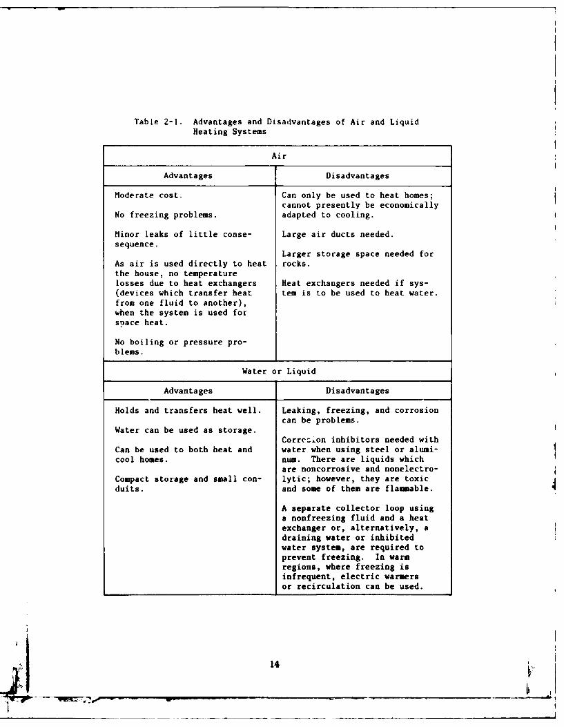
Table 2-1. Advantages and Disadvantages of Air and LiquidHeating Systems
Air
Advantages Disadvantages
Moderate cost. Can only be used to heat homes;cannot presently be economically
No freezing problems. adapted to cooling.
Minor leaks of little conse- Large air ducts needed.sequence.
Larger storage space needed forAs air is used directly to heat rocks.the house, no temperaturelosses due to heat exchangers Heat exchangers needed if sys-(devices which transfer heat tern is to be used to heat water.from one fluid to another),when the system is used forsoace heat.
No boiling or pressure pro-
blems.
Water or Liquid
Advantages Disadvantages
Holds and transfers heat well. Leaking, freezing, and corrosion
Water can be used as storage. cnb rbes
Correz.on inhibitors needed withCan be used to both heat and water when using steel or alumi-
cool homes. num. There are liquids whichare noncorrosive and nonelectro-
Compact storage and small con- lytic; however, they are toxicduits. and some of them are flammable.
A separate collector loop usinga nonfreezing fluid and a heatexchanger or, alternatively, adraining water or inhibitedwater system, are required toprevent freezing. In warmregions, where freezing isinfrequent, electric warmersor recirculation can be used.
14
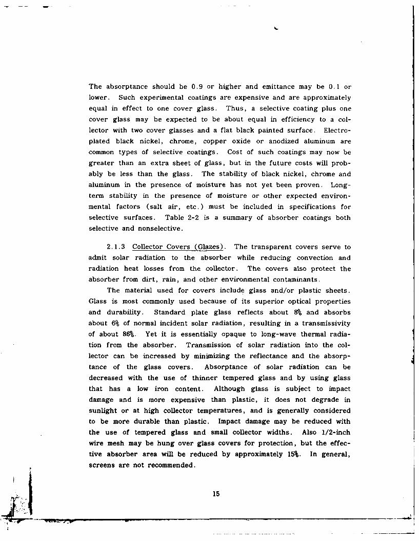
The absorptance should be 0.9 or higher and emittance may be 0. 1 or
lower. Such experimental coatings are expensive and are approximately
equal in effect to one cover glass. Thus, a selective coating plus one
cover glass may be expected to be about equal in efficiency to a col-
lector with two cover glasses and a flat black painted surface. Electro-
plated black nickel, chrome, copper oxide or anodized aluminum are
common types of selective coatings. Cost of such coatings may now be
greater than an extra sheet of glass, but in the future costs will prob-
ably be less than the glass. The stability of black nickel, chrome andaluminum in the presence of moisture has not yet been proven. Long-
term stability in the presence of moisture or other expected environ-
mental factors (salt air, etc.) must be included in specifications for
selective surfaces. Table 2-2 is a summary of absorber coatings both
selective and nonselective.
2.1.3 Collector Covers (Glazes). The transparent covers serve to
admit solar radiation to the absorber while reducing convection and
radiation heat losses from the collector. The covers also protect the
absorber from dirt, rain, and other environmental contaminants.
The material used for covers include glass and/or plastic sheets.
Glass is most commonly used because of its superior optical properties
and durability. Standard plate glass reflects about 8% and absorbs
about 6% of normal incident solar radiation, resulting in a transmissivity
of about 86%. Yet it is essentially opaque to long-wave thermal radia-
tion from the absorber. Transmission of solar radiation into the col-
lector can be increased by minimizing the reflectance and the absorp-
tance of the glass covers. Absorptance of solar radiation can be
decreased with the use of thinner tempered glass and by using glass
that has a low iron content. Although glass is subject to impact
damage and is more expensive than plastic, it does not degrade in
sunlight or at high collector temperatures, and is generally considered
to be more durable than plastic. Impact damage may be reduced with
the use of tempered glass and small collector widths. Also 1/2-inch
wire mesh may be hung over glass covers for protection, but the effec-
tive absorber area will be reduced by approximately 15%. In general,
screens are not recommended.
15
:3
41)A0 0-
:1- 00 0 .4-4) A4 04
0 a) m)
to $ r- -4 -1
4.) 4q =J m41 -n 41 W
> 00 A4J L
4) 4j 4)0 4 )
4) onU 4) %0 c
0 Sn 00 Ln -4
44 A4 )~
0 O
CO00 00 0 00 0
0 4) jJC..0 0 U,
.14 *H r0O 0 C4 N % n Q a 0
(a 0 043CC-4 -4 .40 % -
4) ul .0~0
E-4 ct9E-to 0(A4 0 C3 00 54
41 to~ 0 $ -4 0 -3 N -, -H Ow 4
.00
o0 .4C)l 0 M 0% I . W N
to A 0d 4- 0 0 0 -A 0o LtM -4 M 0 O
.4 to) U4M o r4t1.4 00 m 0 a0 0 0a 0oR4 o R
43 0 ____ _ _ _ _ _ _ _ _ _ _ _ _ _ _ _ _ _ __1_

4) 4J)
41i 04
4.1
V C
0 :3 )0U 4) .0
0 -4
4-)
00U) 4)4
>2 .0 41u n n c-4 "a c 0 N.
0 1-4)
0 4 q4) 0~' 0 0 0
0 En) 04
0 4)c)n0 0 t
4) ~ 0I
o 0
4) A
-4 4 C14
4 .0 * ' .
I) .) c0 00 -4
00 14 0'- . 1- 4 -
o 4) to 0 4) A 4 .C.. -A) Q' $4 4)
0 *1 Cz '. 0 r- A4) m 0 ' a' a
I. LI aav
4)K zI 0
. .. ... .
Most plastic covers transmit the solar spectrum as well or better
than glass glazing. Unfortunately, they transmit infrared radiation well
also, increasing radiation losses from the collector. Table 2-3 compares
the different characteristics of glass and plastic covers (Montgomery,
1978).Although resistant to impact damage, plastics generally degrade in
sunlight and are limited as to the temperatures they can sustain without
undergoing serious deformation. In general, acrylic is the most UV
resistant and polycarbonate offers good impact and high temperature
properties. Teflon FEP film has good transmittance and high tempera-
ture properties, but is limited in strength. Some collectors using
plastic covers are designed to have stagnation temperatures no higher
than 2001-2751F. However, plastic covers have been developed to
withstand 4000F. The manufacturer should be consulted.
Each additional cover, whether it be glass or plastic, reduces
convection heat losses but results in added expense and less solar
radiation transmitted to the absorber. Most commercially available
collectors come with one or two covers. The decision to use one or two
covers depends on the type of absorber coating, the required collection
temperatures, average ambient air temperature, the local wind con di-
tions, and of course, the cost of the covers.
As stated in Section 2. 1.2, the use of a selective surface is about
equal to using one additional cover. Thus for most cases, only one
glass cover is needed if the absorber has a selective coating. In fact,
one study indicated that winter performance was actually reduced by
the use of two glass covers with a selective surface compared to one
cover with the selective surface.
Two covers are generally recommended for use in Northern climates
where winter ambient air temperatures are low. For flat-plate collectors
used mostly for winter heating, one rule of thumb is to use one glass
cover where average winter air is greater than 450F, and two glass
covers in colder climates. Table 2-4 gives some approximations in the
selection of collector covers.
18
4141" 0 w "a I-4 -4 41 4- 41) 4-) 0 0 -4 0 0
-4- 0 r 0 r 0 m 0 0 4),4 ., j 4) r-10 0 4. 0 C. .
.0 P -4 1-4 ,-4 -4 41)4.m0 m -4 -4 -4 -.4 0 0 0 0w) wJ 4) U) W 0) ) - 1Q
4-4 = m )x x x x . $4 w $-4 c4) 41) w4 w w w 4 $4 0 '-4 .4 0
0 4) 0 0 > 444
o4 2
-4 4-4 0
-4l 41) 0 - - C14 -.74 ~ -o x u f If) If)L L() Ul) -7 Lf) C 0 WJ
1.4 ~ 44 It
4 .
4-4
0.)1-4 PC J .0 - 'H $4J 0 C'J C'$4 CO C .) 0 0 0 -4) 44 0C-4 C4. C'.4 C' CN 41) C1 c' 4)
4.) ~ 4. r30 0U ,.- If 0 W.
C4' 0* 41)
$4
m. 0
44 P0, 4 -44. if) If) in) C') "4
m 034-) 0 0 0 0 0 4)o ,-4 41* -... C4 . 4.) 41. 4.1 4.1 4.) WW) 044 w a s0 0 0.4. C)0. 0 ( - 0 V 0 0 W)$4 =0r- 00 r- oy\ 00 .
04 '-44 (A
U 41)
W) -4
1-4 Ea tocr) to C.D (A w)4.
I (a 0a m 4.1c'J "a 0 ' -4 ,-i m 0 0
41 4J . 41 L 4.4 4U) m. - 0
0 00 to 4) 0 .,q m .E5-4 4.) 4J =~ -4 -4 f. 4&. >N04
C3 3) .0 0 -4 0 w~ .14cc $ V 0 U 0 1-4 4J U) c
-4 u 0 0 4) 1-4 <4 4 144 41) -M.000 44 .4 4 004) U 0
di 4- 4 44 .) 4) 5) 0-.j
4.(U 5-4 £3. m~0 0 4) .'.4 .0 0
19
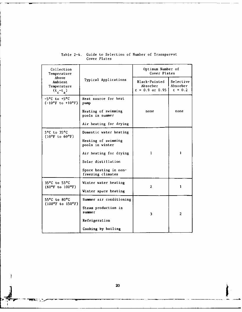
Table 2-4. Guide to Selection of Number of TransparentCover Plates
Collection Optimum Number ofTemperature Cover Plates
AboveAmbient Typical Applications Black-Painted Selective
Temperature Absorber Absorber(tc-ta) E = 0.9 or 0.95 =0.2
-50C to +50 C Heat source for heat(-10 0F to +100 F) pump
Heating of swimming none nonepools in summer
Air heating for drying
50C to 350C Domestic water heating(10°F to 600F)
Heating of swimmingpools in winter
Air heating for drying I
Solar distillation
Space heating in non-
freezing climates
350 C to 550 C Winter water heating(600F to 1001F) 21
Winter spdce heating
55*C to 80*C Summer air conditioning(100OF to 150 0F)
Steam production inslmmer 3 2
Refrigeration
Cooking by boiling
20
2.1.4 Collector Insulation. Insulation behind and to the side ofthe absorber serves to reduce conduction losses. Usually, this insula-
tion consists of 2-6 inches of high -temperature fiberglass batting or
semi-rigid board or even mineral wool. Styrofoam and urethane foams
are usually not used because they may deform at high temperatures or
give off gases (which may be toxic). The insulation should be sepa-
rated from the absorber plate by 1/2 to 3/4 inch and have a reflective
foil facing the absorber plate. If fiberglass insulation is used, itshould not be typical construction grade which contains phenolic
binders that may "outgas" at the stagnation temperature of the collec-
tor. In all cases, specifications should call for insulations that have a
low thermal expansion coefficient, do not melt or outgas at collector
stagnation temperatures (300'-400'F), and (whenever possible) contain
reflective foil to reflect thermal radiation back to the absorber.
2. 1.5 Collector Housings. The housing or collector box serves to
(1) Support the collector components
(2) Protect the absorber and insulation from the environments
(3) Reduce convection and conduction losses from the absorber
Many housing designs are available on the market. They are
constructed of metals, wood, plastics, concrete, and other materials.
The most commonly used materials are aluminum, galvanized sheet metal,
fiberglass laminates, high temperature thermoplastics, and wood
(Montgomery, 1978).* All structural materials are suitable if properly used. However,
most commercially available housings consist of a galvanized sheet metal
box with an anodized aluminum frame which fits on top of the box.Some housings are designed to be integrated directly into the roof
or wall structure, thus reducing construction costs.
Since field labor is expensive, the collector housing should be
designed such that the collector units can be quickly secured in placeand connected to the external piping. Provisions should also be made
21
for easy replacement of broken glass covers. The absorber plate
should be mounted so as to be thermally isolated as much as possible
from the housing.
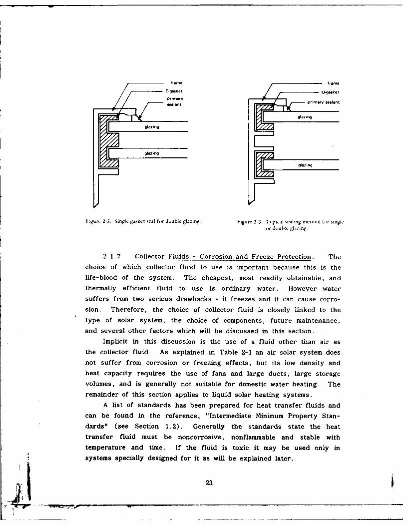
2.1.6 Collector Gaskets and Sealants. Gaskets and sealants must
be carefully selected if a collector is to have a long life. Generally,the housing and the glazing have different rates of thermal expansion.
Gaskets and sealants form the flexible interface between the two compo-
nents and seal out moisture and other contaminants; if they fail, mois-ture will fog the glazing and may possibly damage the absorber coating
and the insulation. These problems can drastically reduce the thermal
performance of the collector.
Two suitable sealing methods are shown in Figures 2-2 and 2-3(Montgomery, 1978). The gaskets provide flexible support and theprimary weather sealant insures against moisture leakage. Dessicants
are sometimes placed between the two glazings to absorb any moisture
that may remain after cover installation.When selecting collector gaskets and sealants, certain material
requirements must be kept in mind. The gaskets and seals must
(1) Withstand significant expansion and contraction without de-
struction
(2) Adhere effectively to all surfaces
(3) Resist ultraviolet degradation
(4) Resist outdoor weathering
(5) Not harden or become brittle
(6) Withstand temperature cycling from -300 to 400OF
Both EPDM and silicone rubbers have been found adequate for use
as gasket materials. Silicone sealants have exceptional weathering
resistance and have received widespread use for many years.
22
framefrm
E-gasket UgsePrimarysealant primary sealant
glaazing
glazing __
glazing
ligure 2-2. Single gasket seal for double glazing. Figure 2-3. T% 131.11 sealing inetliod for singleor double glating.
2. 1.7 Collector Fluids - Corrosion and Freeze Protection. Thechoice of which collector fluid to use is important because this is thelife-blood of the system. The cheapest, most readily obtainable, andthermally efficient fluid to use is ordinary water. However watersuffers from two serious drawbacks - it freezes and it can cause corro-
sion. Therefore, the choice of collector fluid is closely linked to thetype of solar system, the choice of components, future maintenance,and several other factors which will be discussed in this section.
Implicit in this discussion is the use of a fluid other than air asthe collector fluid. As explained in Table 2-1 an air solar system does
not suffer from corrosion or freezing effects, but its low density andheat capacity requires the use of fans and large ducts, large storagevolumes, and is generally not suitable for domestic water heating. The
remainder of this section applies to liquid solar heating systems.A list of standards has been prepared for heat transfer fluids and
can be found in the reference, "Intermediate Minimum Property Stan-dards" (see Section 1 .2). .Generally the standards state the heattransfer fluid must be noncorrosive, nonflammable and stable withtemperature and time. If the fluid is toxic it may be used only insystems specially designed for it as will be explained later.
23
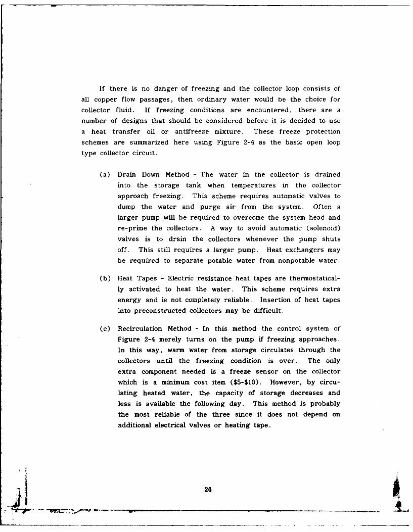
If there is no danger of freezing and the collector ioop consists of
all copper flow passages, then ordinary water would be the choice for
collector fluid. If freezing conditions are encountered, there are a
number of designs that should be considered before it is decided to use
a heat transfer oil or antifreeze mixture. These freeze protection
schemes are summarized here using Figure 2-4 as the basic open loop
type collector circuit.
(a) Drain Down Method - The water in the collector is drained
into the storage tank when temperatures in the collector
approach freezing. This scheme requires automatic valves to
dump the water and purge air from the system. Of ten a
larger pump will be required to overcome the system head and
re-prime the collectors. A way to avoid automatic (solenoid)
valves is to drain the collectors whenever the pump shuts
off . This still requires a larger pump. Heat exchangers may
be required to separate potable water from nonpotable water.
(b) Heat Tapes - Electric resistance heat tapes are thermostatical-
ly activated to heat the water. This scheme requires extra
energy and is not completely reliable. Insertion of heat tapes
into preconstructed collectors may be difficult.
(c) Recirculation Method - In this method the control system of
Figure 2-4 merely turns on the pump if freezing approaches.
In this way, warm water from storage circulates through the
collectors until the freezing condition is over. The only
extra component needed is a freeze sensor on the collector
which is a minimum cost item ($5-$10). However, by circu-
lating heated water, the capacity of storage decreases and
less is available the following day. This method is probably
the most reliable of the three since it does not depend on
additional electrical valves or heating tape.
ii 24
cold watercold water expansion supplysupply tank
storae r, v doble-all to
pump pumps
open loop closed loop with
heat exchanger
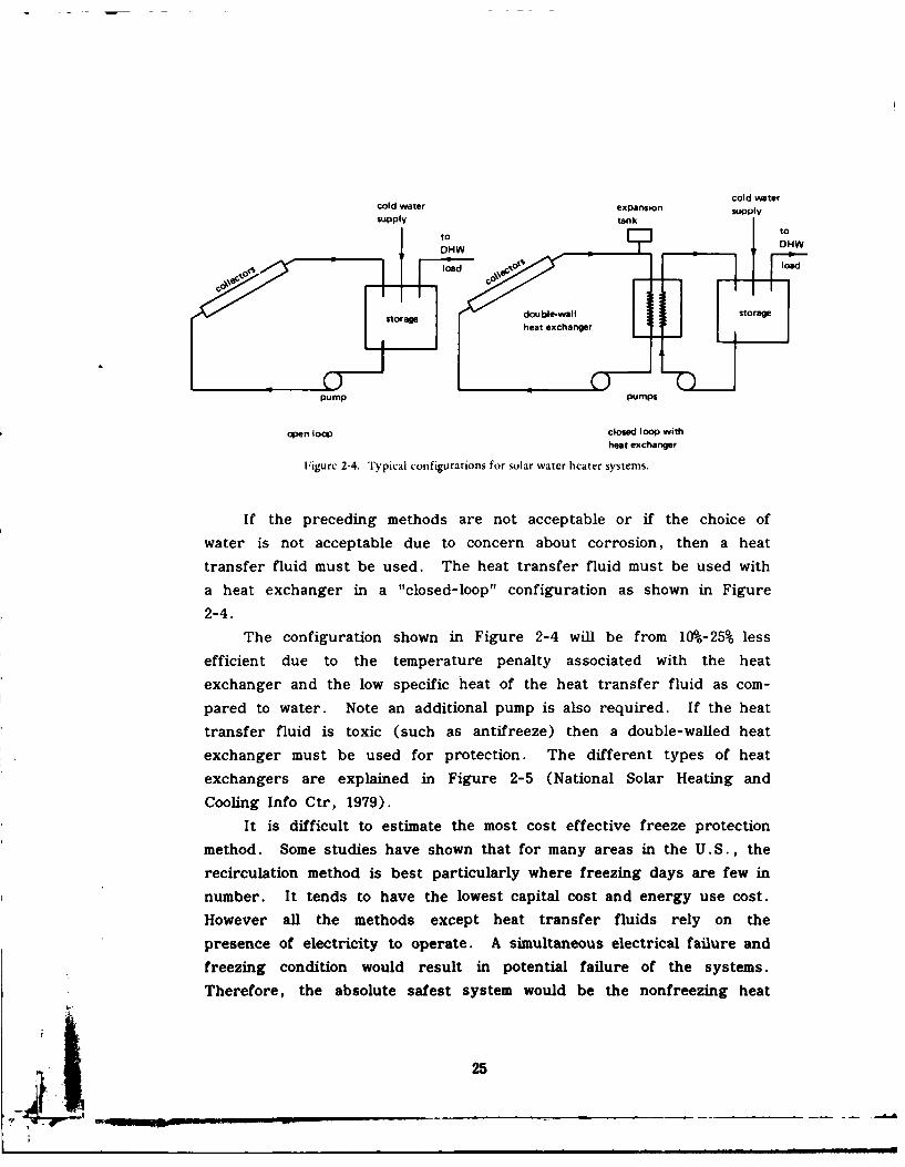
Figure 2-4. Typical configurations for solar water heater systems.
If the preceding methods are not acceptable or if the choice of
water is not acceptable due to concern about corrosion, then a heat
transfer fluid must be used. The heat transfer fluid must be used with
a heat exchanger in a "closed-loop" configuration as shown in Figure
2-4.
The configuration shown in Figure 2-4 will be from 10%-25% less
efficient due to the temperature penalty associated with the heat
exchanger and the low specific heat of the heat transfer fluid as com-
pared to water. Note an additional pump is also required. If the heat
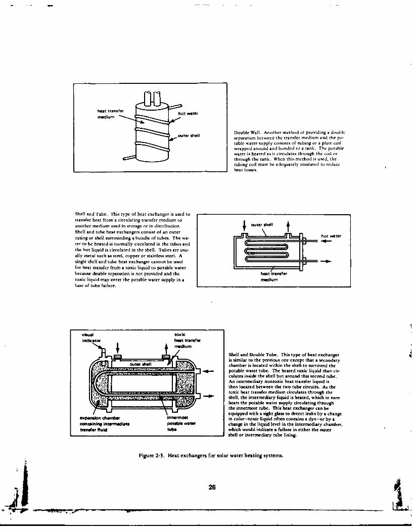
transfer fluid is toxic (such as antifreeze) then a double-walled heatexchanger must be used for protection. The different types of heat
exchangers are explained in Figure 2-5 (National Solar Heating and
Cooling Info Ctr, 1979).
It is difficult to estimate the most cost effective freeze protection
method. Some studies have shown that for many areas in the U.S., the
recirculation method is best particularly where freezing days are few in
number. It tends to have the lowest capital cost and energy use cost.
However all the methods except heat transfer fluids rely on the
presence of electricity to operate. A simultaneous electrical failure and
freezing condition would result in potential failure of the systems.
Therefore, the absolute safest system would be the nonfreezing heat
25
• a -- 2 . ... .. . .
heat transfer hot water
mDouble Wall. Another method of providing a double
, outer shell separation between the transfer medium and the po-
table water supply consists of tubing or a plate coilwrapped around and bonded to a tank. The potablewater is heated as it circulates through the coil orthrough the tank. When this method is used, thetubing coil must be adequately insulated to reduceheat losses.
Shell and Tube. This type of heat exchanger is used totransfer heat from a circulating transfer medium to
another medium used in storage or in distribution. outer shll I
Shell and tube heat exchangers consist of an outer hot watercasing or shell surrounding a bundle of tubes. The wa- -o.--ter to be heated is normally circulated in the tubes andthe hot liquid is circulated in the shell. Tubes are usu-ally metal such as steel, copper or stainless steel. A
single shell and tube heat exchanger cannot be usedfor heat transfer from a toxic liquid to potable waterbecause double separation is not provided and the heat transfer
toxic liquid may enter the potable water supply in a medium'C,tse of tube failure.
visual toxicindicator heat transfer
mShell and Double Tube. This type of heat exchanger
is similar to the previous one except that a secondaryouter shell F chamber is located within the shell to surround the
_potable water tube. The heated toxic liquid than cir-ii:; [- culates inside the shell but around this second tube.
An intermediary nontoxic heat transfer liquid isthen located between the two tube circuits. As thetoxic heat transfer medium circulates through the
-, r" shell, the intermediary liquid is heated, which in turnheats the potable water supply circulating through
the innermost tube. This heat exchanger can beequipped with a sight glass to detect leaks by a change
expansion chanber innermost in color-toxic liquid often contains a dye-or by acontaining intermediate potable water change in the liquid level in the intermediary chamber,
transfer fluid tube which would indicate a failure in either the outershell or intermediary tube lining.
Figure 2-5. Heat exchangers for solar water heating systems.
26
transfer fluids and these might be considered for the very cold parts of
the country (Boston, Chicago, etc.). Each potential project should be
considered individually using local weather criteria, freeze protection
capital costs, additional energy to run the system, reliability, mainte-
nance, and type of system as the criteria. Often a detailed computer
simulation would be required to choose. However, any of the methods
will provide some degree of protection. If heat transfer fluids are
selected for corrosion or freeze protection, the following paragraphs
discuss pertinent criteria.
Before heat transfer fluids are discussed, a review of basic corro-
sion theory is in order. The two types of corrosion which cause the
most damage in solar systems are galvanic and pitting corrosion (Eyre,1978). Galvanic corrosion is a type of corrosion which is caused by an
electrochemical reaction between two or more different metals in contact
with each other. A chemical reaction between the metals causes a small
electrical current which erodes material from one of the metals. Solar
energy systems generally contain a number of different metals such as
aluminum, copper, brass, tin, and steel. This makes the solar system
a prime candidate for galvanic corrosion. If the dissimilar metals are
physically joined or if they are contacted by a common storage or
heat-transfer fluid, the possibility of galvanic corrosion becomes much
greater.
Pitting corrosion is a highly localized form of corrosion resulting in
deep penetration at only a few spots. It is one of the most destructive
forms of corrosion because it causes equipment to fail by perforation
with only a very small weight loss. When heavy metal ions such as iron
or copper plate out on a more anodic metal such as aluminum, a small
local galvanic cell can be formed. This corrosion spot or "pit" usually
grows downward in the direction of gravity. Pits can occur on vertical
surfaces, although this is not as frequent. The corrosion pits may
require an extended period (months to years) to form, but once started
they may penetrate the metal quite rapidly.
Heavy metal ions can either come as a natural impurity in a water-
mixture heat transfer fluid or from corrosion of other metal parts of the
solar system.
27
Pitting corrosion has the same mechanism (concentration cell) as
crevice corrosion thus it can also be aggravated by the presence of
chloride or other chemicals which can be part of the water mixture or a
contaminant from solder fluxes. Aluminum is very susceptible to pitting
corrosion, while copper generally is not.
There are several preventive measures which will eliminate or at
least minimize galvanic and pitting corrosion in collector systems which
use an aqueous collector fluid. Galvanic corrosion is prevented by
using nonmetallic connections between dissimilar metals. Pitting corro-
sion is essentially eliminated if copper absorber plates are used. Corro-
sion inhibitors can minimize pitting corrosion in aluminum absorbers.
The types of heat transfer fluids available may be divided into two
categories, nonaqueous and aqueous. Silicones and hydrocarbon oils
make up the nonaqueous group, while the aqueous heat transfer fluids
include untreated potable (tap) water, inhibited- distilled water, and
inhibited glycol/water mixtures. The potable tap water and inhibited
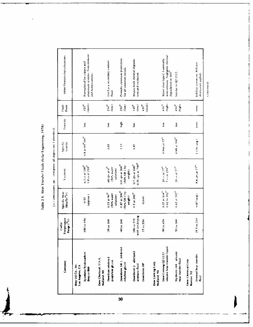
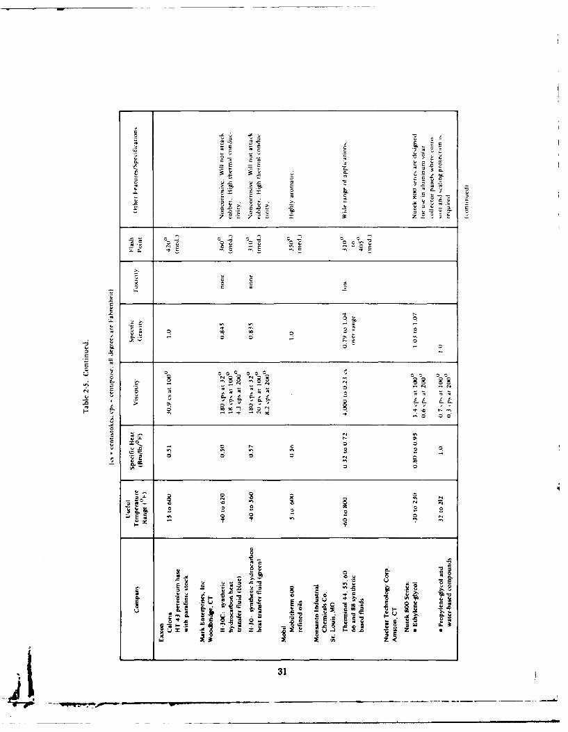
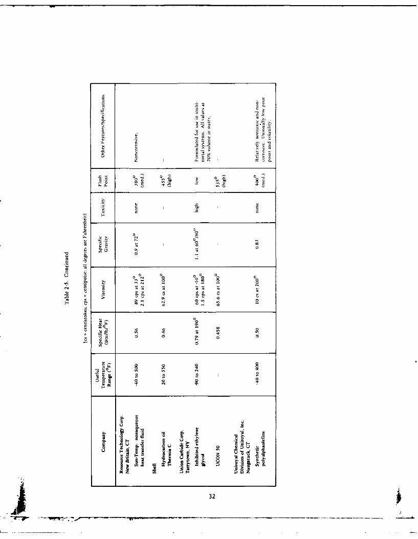
distilled water do not, of course, offer freeze protection. Table 2-5
shows characteristics of some of the most common heat transfer fluids.
2. 1.7. 1 Silicone Fluids: Silicone heat transfer fluids have
many favorable properties which make them prime candidates for collec-
tor fluids. They do not freeze, boil, or degrade. They do not cor-
rode common metals, including aluminum. They have excellent stability
in solar systems stagnating under 4001F. Silicone fluids are also virtu-
ally nontoxic and have high flash and fire points. Current evidence
indicates that silicone fluids should last the life of a closed-loop collec-
tor system with stagnation temperatures under 350 0-4001F. The flash
point is fairly high, 4501F, but since the HUD standards state that heat
transfer fluids must not be used in systems whose maximum stagnation
temperature is less than 100*F lower than the fluid's flash point, this
limits most silicone oils to systems with a maximum temperature of 350IF
or less. Also silicones do not form sludge or scale, so system perfor-
mance does not decrease with time.
28
The main drawback of silicone fluids is their cost. Currently
silicone fluid costs about $20-$25 per gallon. Thus the cost of the 20
to 30 gallons of collector fluid required for a typical 500 ft2 collector
system becomes considerable. As with hydrocarbon oils, the lower heat
capacity and higher viscosity of silicone fluid requires larger diameter
and more expensive piping. Due to the higher viscosity, larger pumps
will be required and subsequent higher pumping costs. One other
problem with silicone fluids is the seepage of fluid at pipe joints. This
problem can be prevented by proper piping installation and by pres-
surizing the system with air to test for leaks. There have also been
reports of seepage past the mechanical seals of circulating pumps.
Silicones have the advantage of lasting the life of the system
with little maintenance. While this helps minimize operating expenses,
the initial cost of silicones is markedly higher than that of other avail-
able heat transfer fluids. However, the high initial cost of silicone
heat transfer fluid may be less than the savings that result from mini-
mum maintenance and no replacement of collector fluid. The use of
silicone fluid allows aluminum absorbers to be used without fear of
corrosion. The savings gained from the use of aluminum absorbers as
opposed to copper absorbers could be substantial.
2.1.7.2 Hydrocarbons: Hydrocarbon oils, like silicones, also
give a long service life, but cost less. They are relatively noncorro-
sive, nonvolatile, environmentally safe, and most are nontoxic. They
are designed for use in systems with lower operating temperatures,
since some brands break down at higher temperatures to form sludge
and corrosive organic acids. Typical closed-cup flashpoints run from
300'F to 4201F, but the fluids with higher flashpoints have a higher
viscosity. The HUD bulletin on minimum property standards for solar
heating systems recommends a closed-cup flashpoint 100*F higher than
maximum expected collector temperatures.
Unsaturated hydrocarbons are also subject to rapid oxidation
if exposed to air, necessitating the use of oxygen scavengers. Some
hydrocarbons thicken at low temperatures and the resultant higher
viscosity can cause pumping problems.
29
C
C
- -' 04
~-~- toC~ EC --
-~ 0-4' C
0 '0'4 - *0S S ~0
to -
-~ - S
C - C ~ C
0 -~ 0 -.1-~ O~
E -t C
-. .C
r-.. -0'
CI- to N x04
to 0 -
0' 0'
0 -0- N
~ 3.0 Ot, NO
- C eJ~ - - N N
-~ t. ~ - -tot. S ~ to~~'S o..~2 4'"~ 4' C-~ e-~~ e-~
C 0'~' 0 - -f~ C. - too f-IN f-I
001 -U 0
- 0 ~. -- --- to~- -. 0 f-I -C - ~--~ 0~
01.~ ~ ~ N?0 -~0 ~..c oo~ ~0 to
II~.2 N ~ ~1~ -to Nf-0 N
z to 0~0 - - - -0~- 0~ -- -
'I- 0 ~-o z
*0 mel *r. -0 - ~ -t -,
- 0 00- 0 0 0
4 2g 0 - I'- f.m - 010 mel 2
01~ - to9-.
'*0
C ~ ~. 01
* -~ 'C to' - 01C -~ 04
01 -
j f-IC f- C. ~-- ~1
0 -' ZO v A. CI C' ' C ~ int~~ -C;
- ~' - s~ t.~U - - - 4 .C
01~ 01 ~ 0~ Em. E'~
'C
30 1
o -:,-~ -.
- ~ L~-~C
-'S -- '*oo~ C~C C
~ ~ C-
2 -~ -~ 2~
.5 = tJ - C
7~ 1= -
A C *~- - - '-I..- IA - .5 0
.~2 ~E
C CC 0C =
0
r% Ifl - C*1~ ~ 0
0 CL0 ~'IA
0'C4-CC
C
-~ 000 o~0 -.C 00
o - -C.t' A -AC- AC-C- 0 A AC-C- C-C-
' o~C. 'fl N0 " tC C~-~-t ~0 00
0
~z.C
- - o r-.CS en 0 -s
C. In In In
A 0 0 N
- ~ 0 0U,
0N C
~U-. C C N
~ 2 2 2 2 oen 0 ~ 0 N
'Ax - 1~ ~ In oC
C0
* Co CoI-..-CU 0
E~ c *-g~ '-~- ~
.~ ~ ~,U0C C~ " ~
~ ~'A
I ~0
31
0
a .- a0~ C
E ~00 a
C-~
0 0~0 0~00 -0~ 0
00>..~. l's o
4, o ~~00 5.-a
-' 0 - 00002: I ~. or-. C-
.0~' -~ 0 ~
oC 0 -~ ,~ ~ e2 -
5..0
0 00 - C
0 0 .0 0
00 '0
N4, 4 0
4- 00 '0 60'
U 0
C
o 4,
00
N 0 0.~- 0 0
- - - 04, 4- 4, 4- N
N 00 0 00 a14 U 0 0 00 0 0
0 C-C- 14 C-C. 14 0.0 1' 1414 11
0'~ 0~ ,,., 000 4N '0 -
N '0 - '0
0 044- 04~.0~ 0'
04, ~ - CC
4" 014 14.0 a .~. 4"
o 6 0~ 0
6
4,~~ 0 0o~Z. 0 0
00'..0 0
2 S I0 0 0 0
N 0'
00 4,04, C
~ .~ ~ S ~ -~ C
U CC
2 0 44> s, ES~-o ~ ~U ~Z.
0 o ~u
~
-C '~
__ _________ 4
Newer hydrocarbons are being developed which do not harm
rubber or materials of construction, since this has been a problem with ,.
hydrocarbons. In general, they cannot be used with copper, as it
serves as a catalyst to fluid decomposition. The thermal conductivity of
hydrocarbons is lower than that of water, although the performance of
some brands is much better than others.
The cost of typical hydrocarbon heat transfer oils vary from
about $3/gal to $7/gal. A typical liquid collector of 500 ft 2 plus the
piping to and from storage will require from 20 to 30 gallons of collector
fluid. The lower heat capacity and higher viscosity of these oils will
also requite larger diameter pipe, increasing materials costs further. If
hydrocarbon fluids are used, the additional capital cost should be
compared with expected savings due to lower maintenance costs. The
use of aluminum absorbers rather than copper absorbers will also result
in substantial savings.
2.1.7.3 Distilled Water: Distilled water has been suggested
for use in solar collectors since it avoids some of the problems of un-
treated potable water. First, since the distillation process removes
contaminants such as chlorides and heavy metal ions, the problem of
galvanic corrosion, though not completely eliminated, should be allevi-
ated. However, distilled water is still subject to freezing and boiling.
For this reason, an anti-freeze/anti-boil agent such as ethylene glycol
is often added.
2.1.7.4 Water/Antifreeze: Nonfreezing liquids can also be
used to provide freeze protection. These fluids are circulated in a
closed loop with a double wall heat exchanger between the collector loop
and the storage tank (see Figure 2-5).
Water/antifreeze solutions are most commonly used because
they are not overly expensive. They range from $3-$4 per gallon
including inhibitors. Ethylene and propylene glycol are the two most
commonly used antifreezes. A 50-50 water/glycol solution will provide
freeze protection down to about -301F, and will also raise the boiling
point to about 230*F.
33
The use of water/glycol solution presents an additional corro-
sion problem. At high temperatures glycols may break down to form
glycolic acid. This acid corrodes most all metals including copper,
aluminum. and steel. The rate of glycol decomposition at different
temper1t~ires is still a subject of uncertainty. The decomposition rate
of glycul varies according to the degree of aeration and the service life
of the solution. Most water/glycol solutions require periodic monitoring
of the pli level and the corrosion inhibitors. If these solutions are
used in the collector loop, the seller should specify the expected life of
the solution and the amount of monitoring required. The cost of peri-
odic fluid replacement and monitoring should be considered in the
economic analysis.
Since glycol-water mixtures do require a lot of maintenance
(and since homeowners can be quite negligent) it is recommended that
glycols not be used in home solar heating and domestic hot water
systems, and that glycol-water solutions be reserved for use in large-
scale installations which have regular maintenance schedules and where
the high cost of silicone oils would be prohibitive.
2. 1.8 Collector Connections. Water flow through nonhorizontal
collectors should always be against gravity, except in trickle-type
collectors. Usually this means water inlet to the collector at the
bottom, and outlet at top. Care must be taken so that equal flow goes
to all tubes. If manifold AP is large, then center tubes will get little
flow. The design most usually used is one in which the collectors are
connected in parallel. This results in low pressure drop and high
efficiency of each collector. A series hookup results in the highest
temperature and the highest pressure drop but lowest collector effi-
ciency. Higher temperatures than in the parallel arrangement may be
obtained with parallel-series connections, but at the expense of reduced
efficiency and greater cost. These high temperatures are not usually
required for hot water and space heating. Figure 2-6 shows different
connection configurations. Very large installations may merit computer
simulations to optimize the various connections of each stage.
34
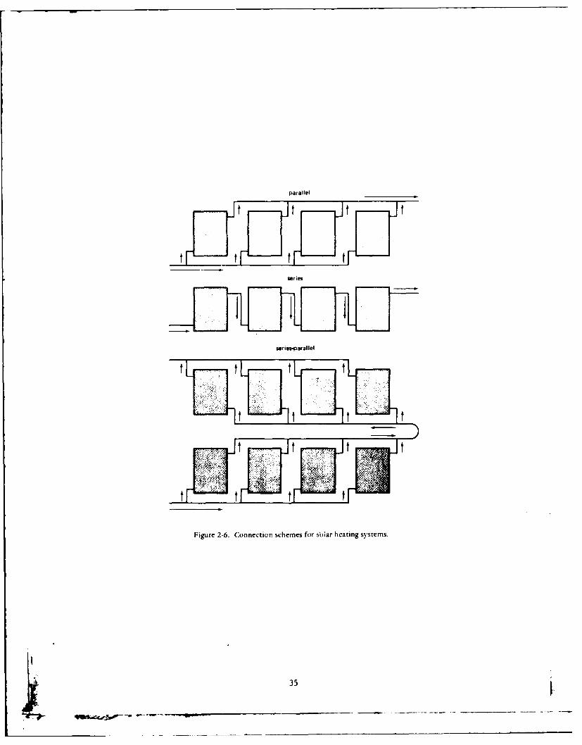
parallel_________
series
seriesparal lel
Figure 2-6. Connectier'. schemes for sbiar heating systems.
-~ -.---- ~35
2. 1.9 Collector Efficiency and Heat Losses. In the precedingsections, many details as to the construction and choice of components
of a solar collector have been given. All of these features contribute
to how well a collector will perform or how efficient it will be. Solar
collectors, depending on their construction and materials, suffer from
several kinds of heat losses. They can lose heat by convection of wind
blowing over their top and bottom surfaces. As the collector tempera-
ture increases above the temperature of the surrounding air, the raidia-
tion heat losses increase. This results in lower heat collected (lower
efficiency) at higher collector temperatures. Heat can be lost by con-
duction from the back and sides of a collector. To evaluate the effectsof all these parameters individually would involve detailed and difficult
calculations.
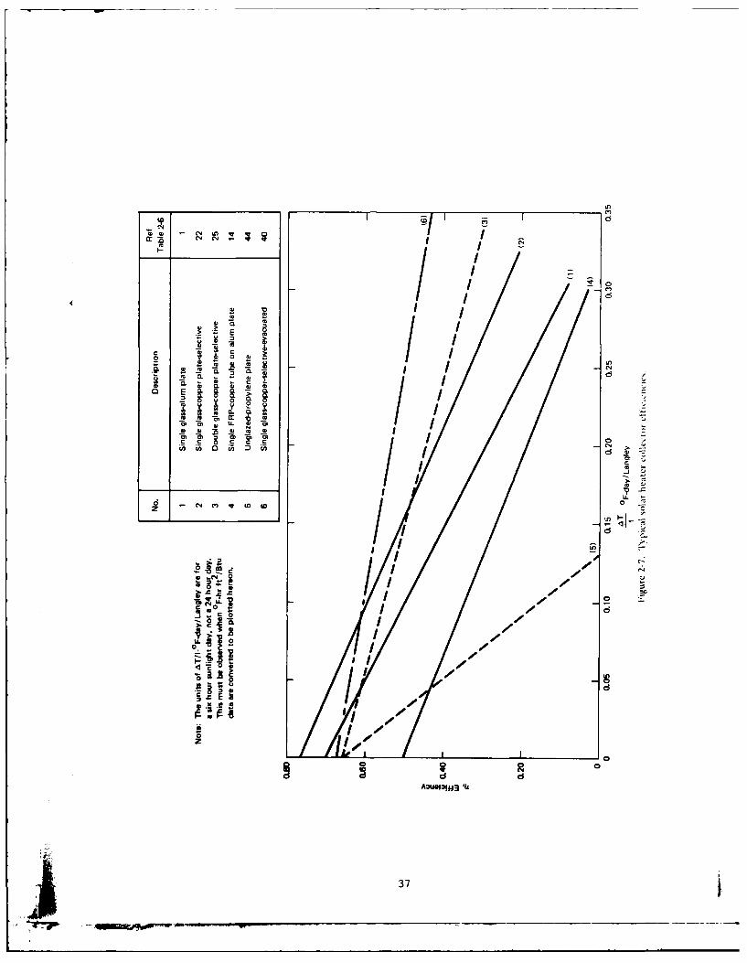
Fortunately, collector performance can be compared much more
easily by a single graph depicting collector efficiency versus the param-
eter AT/I. Collector efficiency is defined as the ratio of the heat
collected to the insolation (1) falling on the surface of the collector.
Also.
AT =T. - TI a
where T. temperature of fluid entering collector (inlet)
T a ambient air temperature
Figure 2-7 gives the efficiency of some typical flat plate solar
collectors. The most efficient solar collector would convert 100% of the
s's energy faling on it to usable heat. As shown in Figure 2-7, this
is impossible so the designer looks for a collector that converts thegreatest percentage of solar energy to heat, at the required tempera-
ture, and at the lowest cost.
It is important that each collector be tested according to an exact-
ing standard. The early standard for testing solar collectors was
NBSIR 74-635 published by the National Bureau of Standards (Hill andKusada, 1974). This is the standard the previous edition of this report
used to report collector efficiencies. Subsequently, the American
Society of Heating, Refrigerating, and Air Conditioning Engineers, Inc.
36
~~I a
III4 M
m c
LLE
to cc I D6~r.z
iicE I /I i.
.4'1
IL 0
z IDE ;II 6 *
'dodIll I*#4 *$
37,
(ASHRAE) sponsored the development of a uniform method of testing
solar collectors to form the preliminary standard 93-P and finally the
version in use today, Standard 93-77, "Methods of Testing to Determine
the Thermal Performance of Solar Collectors." This method uses the
Hottel-Whillier equation and is generally accepted in the solar industry.
The differences between the NBS and the ASHRAE standard are as
follows:
1. ASHRAE requires the use of gross collector area rather than
aperture or net area used in NBS.
2. ASHRAE uses the collector inlet temperature as one of its
parameters whereas NBS uses the average absorber plate
temperature defined as the sum of the inlet and outlet tem-
peratures divided by two.
In general, the NBS standard will give higher collector efficien-
cies, possibly 5%-10%, but the accepted consensus standard at this time
is the ASHRAE 93-77 standard. The Department of Energy (DOE) is
using the ASHRAE standard in developing its program for national
certification and rating of solar collectors. Therefore, all data given in
this report and future reports will conform to the ASHRAE standard.
Figure 2-7 shows many contemporary solar collectors as of the
writing of this report. Data is from ASHRAE 93-77 tests. In some
cases CEL has conducted the test itself. A typical CEL test report of a
solar collector is given in Durlak (1979a) which is the latest report. It
summarizes other reports available.
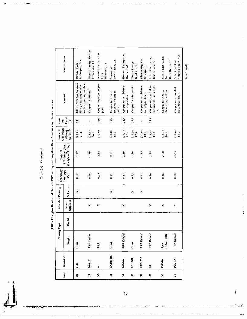
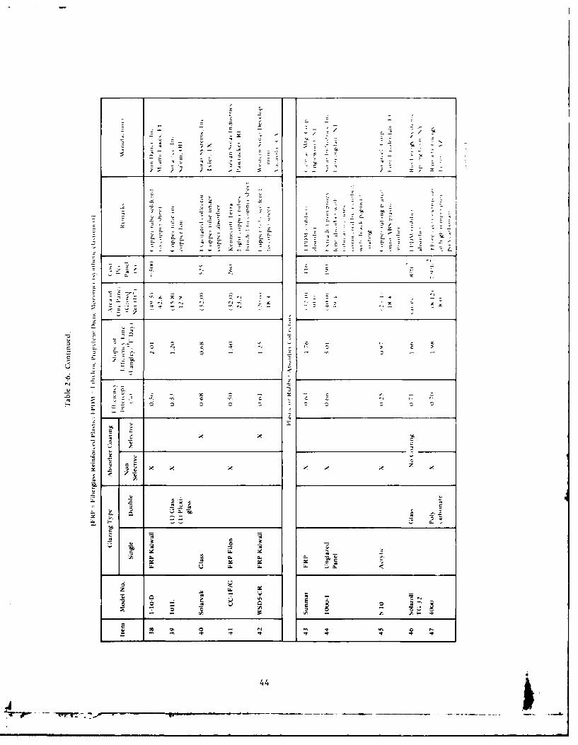
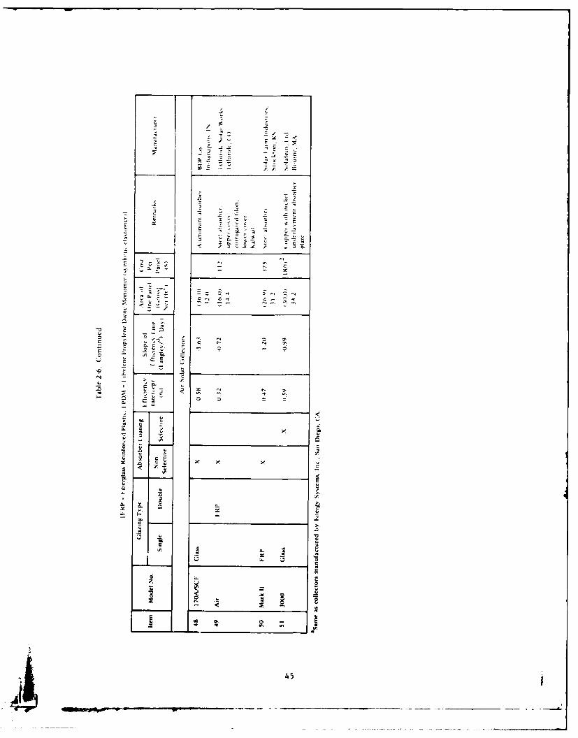
A large amount of test data on solar collectors is becoming avail-
able through the national program run by DOE, the CEL tests, and
individual laboratories testing for the manufacturers. Some of this data
is shown in Table 2-6, which is the basis for Figure 2-7.
Table 2-6 represents a random sampling of the many solar collec-
tors available. It is not a comprehensive list nor is it an endorsement
of any particular collector. These data were excerpted from Durlak
'A 38
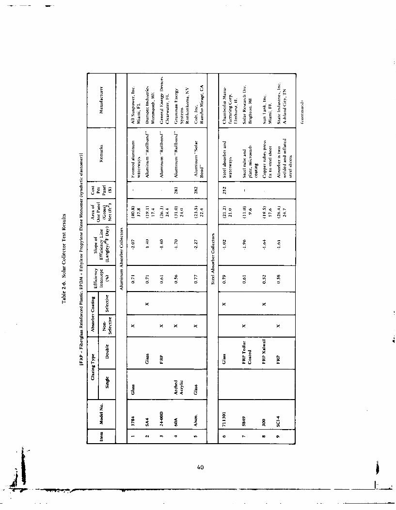
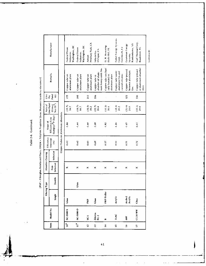
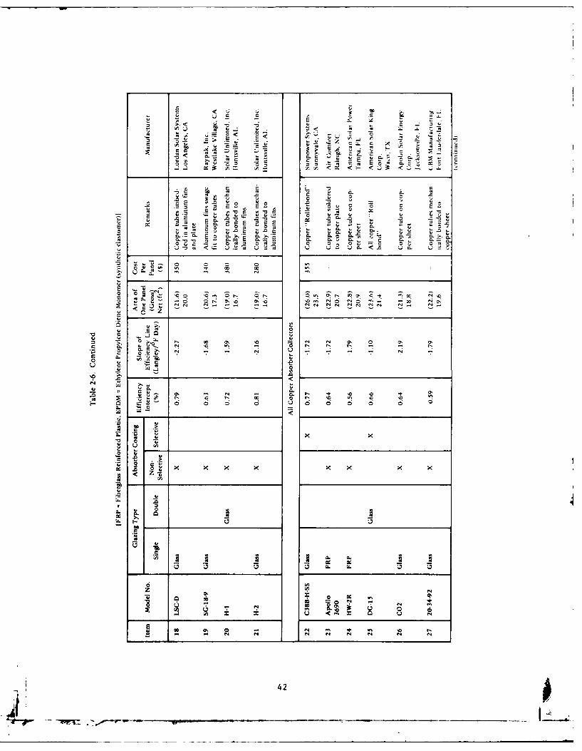
(1979a), Florida Solar Energy Ctr (1979), and Solar Age Magazine(1979). The main criteria for each collector in Table 2-6 is that it havean accepted ASHRAE 93-77 performance test. Other than that, collec-tors were chosen to provide a variety of types, materials, construction
techniques, geographical locations, and cost information. A few cau-tions are advisable. Prices may be up to 1 year old from the publi-cation date and should be checked if a purchase is anticipated. Manu-facturers may have other models available. For example, Table 2-6 may
give details for a single glazed collector and chances are the manufac-turer would also have a double glazed model with valid ASHRAE 93-77test data. The user may know of other collectors with test data avail-able. These could be readily c'--Tpared to similar models in Table 2-6.
To select a collector from -able 2-6, first note that collectorsconstructed of similar materials (copper, aluminum, etc. ) are groupedtogether. Then, it is necessary to pay attention to the y intercept(called efficiency intercept in Table 2-6) which gives the highest effi-
ciency of a collector, and the slope which gives a measure of the rateat which the collector efficiency decreases. These parameters winl be
used later in estimating the solar collector performance. In general themore negative the slope, the less efficient the collector. However, thismust be balanced with the value of the efficiency intercept. Forexample, in Figure 2-7 and TaJ)Ie 2-6 note that double glazed collectors
start out at a lower instantaneous efficiency (y-intercept) but do notlose efficiency very fast (less negative slope) so that when comparingwith single glazed collectors the operating temperature (T.i) will ulti-
mately determine which is best (see Table 2-4 also). When the cost ofthe collector is also considered, it becomes very difficult to "intuitively"pick a best collector in Table 2-6. The user should consider severaloptions of collectors when using the worksheets in the later sections.In choosing a collector Figure 2-7 should be used only for qualitativejudgments, while Table 2-6 should be used for typical slope and inter-cept values . This avoids the errors associated with trying to "read
off" numbers on Figure 2-7.
39
C7 z
rEEc E E E
0C.
E c -t -t
C2 C -t.
oo be
Z -
< z
C.
2 ~.t -
-~ *~** O '"- S~0 C N 40-
LE C.
C 0 0 E E uC 0L
0. CL-
~ 0 0 mC8E cr0 E cE
0 0
'LL; ~ 0
9 0 0 6 9L ..
.~ ~ -- - -.- N O '<
C, -41
E E~ < o c
-0 0
0 0 - C0 0 o
in* EZ ci ci 6 6 0 0 0 z~ .0 00. <
>0
CL -~ .0 0
UNO 0 ~ 0 0 0 0 ~ Ot
*x x~'-O~
0t' t, * 0
z0
It
,z
ob o 1cc = g f 0 a' a
0 0. 4'~-. N 'C ' .- 0 r. 4. r- OD
4.42
M r
cl4. v 4,
m.~ 0 .0 . LaE 0 0 00<
.00
uz e n%'% 4
~~~~~ x~~ ~-
41
CL
ILq. .. gL.
'4
f4
4.1 t,0
- ii 43
- I . - . - _ --
c~ *.
C
- • I, . ..
v c
Ll. LL
z W
Z|
7~ -
00 *1 N -- ,~ -t
-' C'
..- -=
-<, ,'a .'
4E
~E
± -
- B;: ' '5
2.'.10 Other Types of Solar Collectors. The three most common
types of solar collectors are flat plate collectors, evacuated tube collec-
tors and concentrating collectors. Due to certain cost and performance
advantages, flat plate collectors have been Used extensively for domes-
tic water heating and space heating applications. Evacuated tube and
concentrating collectors are used mostly in solar applications requiring
very high temperatures. A brief description folluws.
2.1.10.1 Evacuated-Tube Collectors: Figure 2-8 shows an
evacuated-tube collector. This type of collector uses a vacuum between
the absorber and the glass outer tube to significantly reduce convection
and conduction heat losses.
Evacuated-tube collectors operate essentially the same as
flat-plate collectors. Solar radiation passes through the outer glass
tube and is abosrbed by the coated absorber. [feat energy is trans-
ferred to fluid flowing through the absorber.
Most evacuated-tube designs collect both direct and diffuse
radiation efficiently, but certain types are specifically designed for
more efficient collection of direct radiation. Although evacuated-tube
collectors are considerably more expensive than typical flat-plate collec-
tors, they are much more efficient when high collection temperatures
are needed for operating absorption chillers or for industrial pro-
cessing.
They may not be as efficient as flat-plate collectors at low-
temperature applications such as domestic water heating and space
heating. Comparisons can be made using" data similar to that in
Figure 2-7 and Table 2-6.
2.1.10.2 Concentrating Collectors: Concentrating or focus-
ing collectors intercept direct radiation over a large area and focus it
onto a very small absorber area. These collectors can provde very
high temperatures more efficiently than flat-plate collectors, since the
absorption surface area is much smaller. However, diffuse sky radia-
tion cannot be focused onto the absorber. Most concentrating collectors
require mechanical equipment which constantly orients the collectors
towards the sun and keeps the absorber at the point of focus.
46
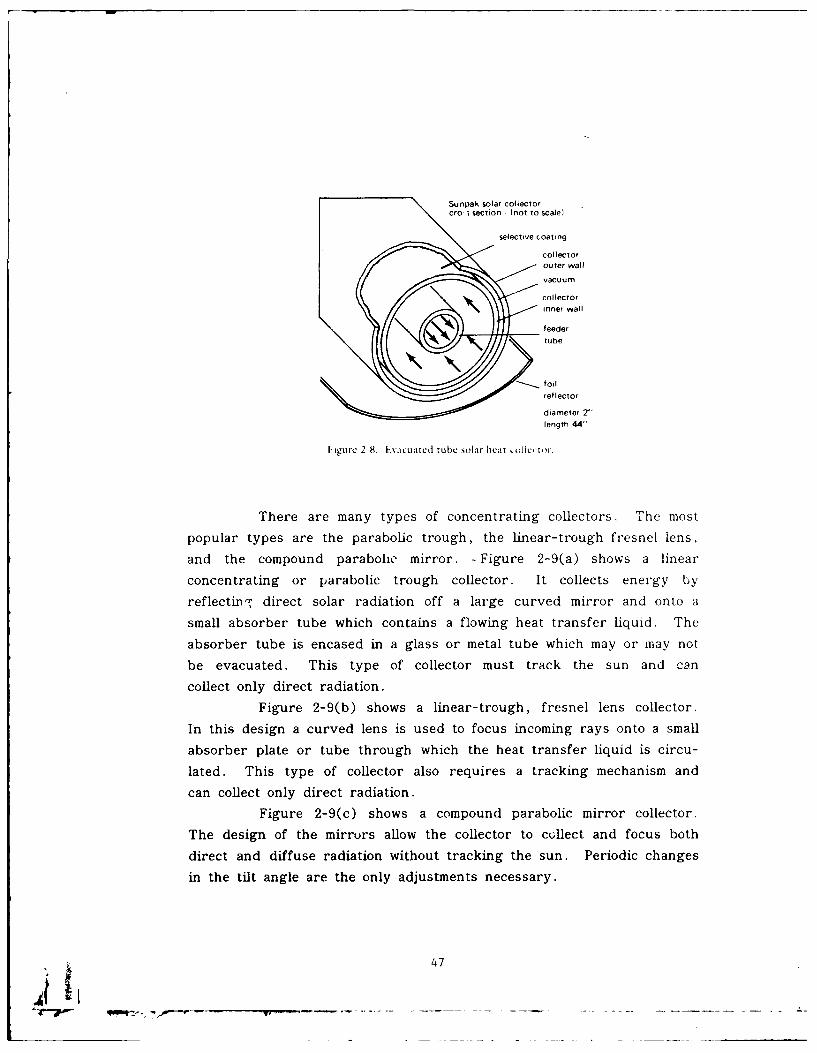
Sunpak solar collectorcr0' section - (not to scale
selective coating
collector
outer wall
vacuum
collectorinner wallI
feedertube
reflector
diameter 2"length 44"
ligUre 2-8. tEVACLlated tube solar hecat k oiictoi.
There are many types of concentrating collectors. The mostpopular types are the parabolic trough, the linear-trough fresnel lens,
and the compound parabolic mirror. -Figure 2-9(a) shows a linear
concentrating or parabolic trough collector. It collects energy by
reflectinw direct solar radiation off a large curved mirror and onto a
small absorber tube which contains a flowing heat transfer liquid. The
absorber tube is encased in a glass or metal tube which may or may not
be evacuated. This type of collector must track the sun and can
collect only direct radiation.
Figure 2-9(b) shows a linear-trough, fresnel lens collector.
In this design a curved lens is used to focus incoming rays onto a small
absorber plate or tube through which the heat transfer liquid is circu-
lated. This type of collector also requires a tracking mechanism and
can collect only direct radiation.Figure 2-9(c) shows a compound parabolic mirror collector.
The design of the mirrors allow the collector to collect and focus both
direct and diffuse radiation without tracking the sun. Periodic changesin the tilt angle are the only adjustments necessary.
47

beam radiation
from across
the skyi
fresnel curved lens/
.receiver
pla nsulated
liquid absorber plate
(a) parabolic trough evaculated
b) linear-trough, fresnel lens tubecollector
(c compound parabolic mirror
IFigurc 2-9. Cirnicntrating coll'ectors lr solar cncrgy.
Direct radiation is intercepted by only a portion of the mirror
at a time, thus this collector does not collect as much solar energy as a
focusing collector which tracks the sun. It is, however, less expensive
to install and maintain. The absorber tube is encased within an evacu-
ated tube to reduce heat losses.
Many other types of concentrating collectors have been devel-
oped which produce high temperatures at good efficiencies. However,
the high cost of installing and maintaining tracking collectors restricts
their use to solar cooling and industrial applications where extremely
high fluid temperatures are required. In addition, concentrating collec-
tors must be used only in those locations where clear-sky direct radia-
tion is abundant.
2.2 Energy Storage and Auxiliary Heat
Since effective sunshine occurs only about 5 to 6 hours per day
(in temperate latitudes), and since heating and hot water loads occur
up to 24 hours a day, some type of energy storage system is needed
-. -48
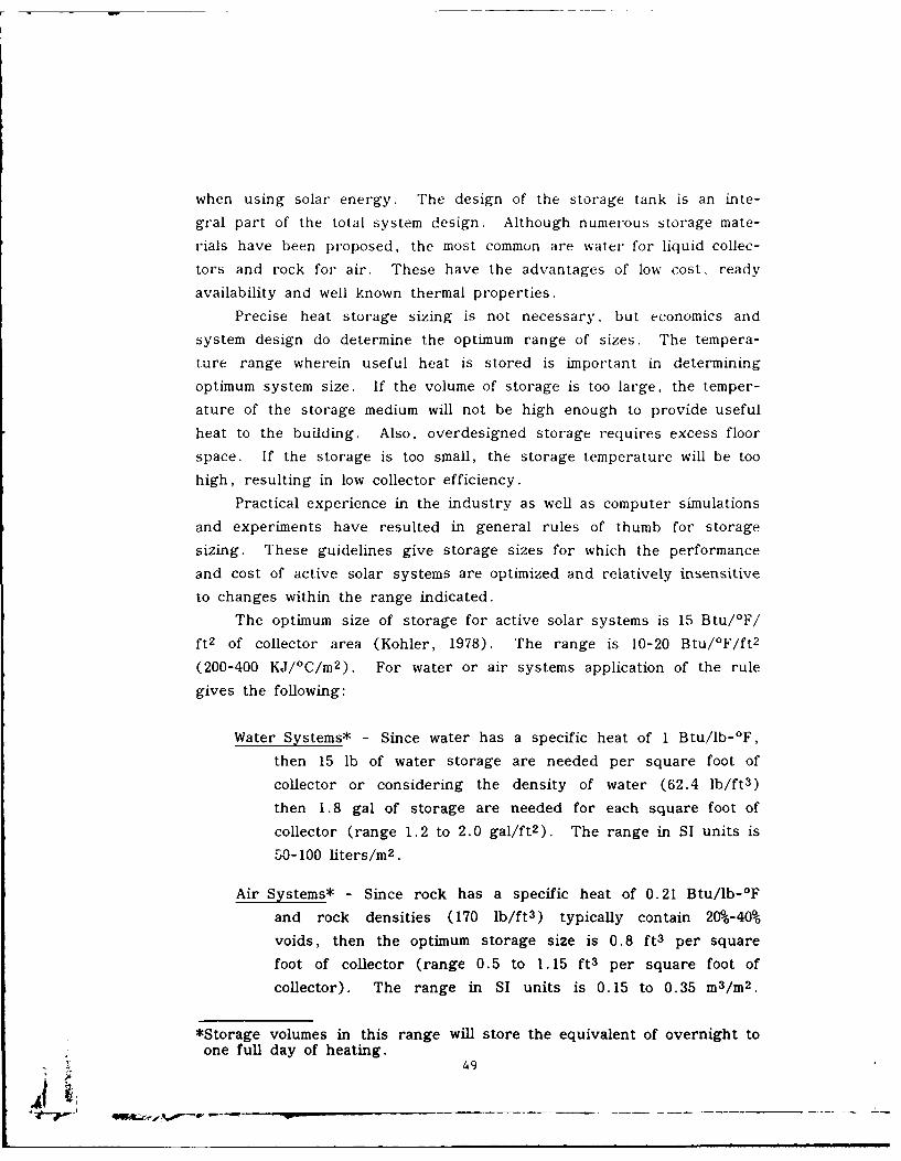
when using solar energy. The design of the storage tank is an inte-
gral part of the total system design. Although numerous storage mate-
rials have been proposed, the most common are water for liquid collec-
tors and rock for air. These have the advantages of low cost, ready
availability and well known thermal properties.
Precise heat storage sizing is not necessary, but economics and
system design do determine the optimum range of sizes. The tempera-
ture range wherein useful heat is stored is important in determining
optimum system size. If the volume of storage is too large, the temper-
ature of the storage medium will not be high enough to provide useful
heat to the building. Also, overdesigned storage requires excess floor
space. If the storage is too small, the storage temperature will be too
high, resulting in low collector efficiency.
Practical experience in the industry as well as computer simulations
and experiments have resulted in general rules of thumb for storage
sizing. These guidelines give storage sizes for which the performance
and cost of active solar systems are optimized and relatively insensitive
to changes within the range indicated.
The optimum size of storage for active solar systems is 15 Btu/OF/
ft 2 of collector area (Kohler, 1978). The range is 10-20 Btu/OF/ft 2
(200-400 KJ/°C/m 2 ). For water or air systems application of the rule
gives the following:
Water Systems* - Since water has a specific heat of 1 Btu/lb-°F,
then 15 lb of water storage are needed per square foot of
collector or considering the density of water (62.4 lb/ft3)
then 1.8 gal of storage are needed for each square foot of
collector (range 1.2 to 2.0 gal/ft 2 ). The range in SI units is
50-100 liters/m 2 .
Air Systems* - Since rock has a specific heat of 0.21 Btu/lb-OF
and rock densities (170 lb/ft 3 ) typically contain 200-40%
voids, then the optimum storage size is 0.8 ft 3 per square
foot of collector (range 0.5 to 1.15 ft 3 per square foot of
collector). The range in SI units is 0.15 to 0.35 m3 /m 2 .
*Storage volumes in this range will store the equivalent of overnight toone full day of heating.
49
N-00-1
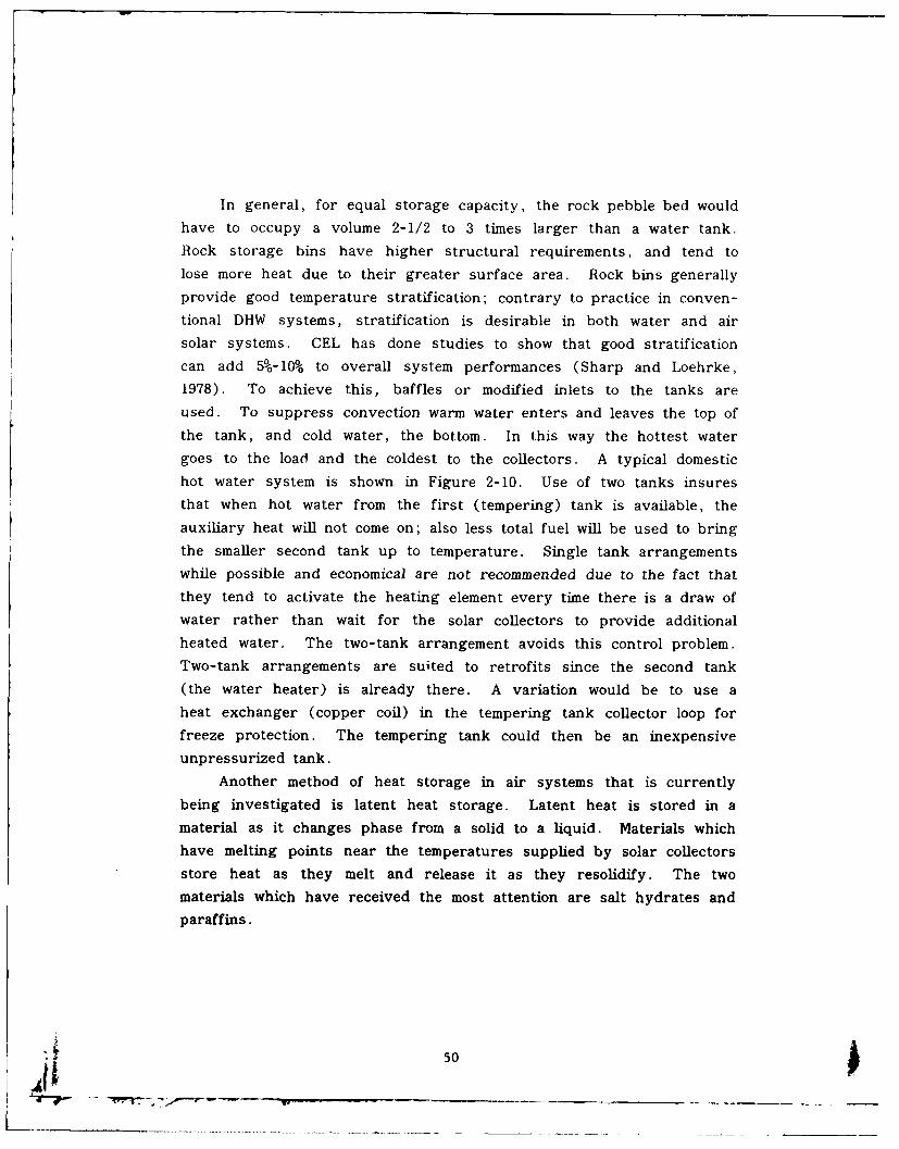
In general, for equal storage capacity, the rock pebble bed would
have to occupy a volume 2-1/2 to 3 times larger than a water tank.Rock storage bins have higher structural requirements, and tend tolose more heat due to their greater surface area. Rock bins generallyprovide good temperature stratification; contrary to practice in conven-tional DHW systems, stratification is desirable in both water and airsolar systems. GEL has done studies to show that good stratificationcan add 5%-10% to overall system performances (Sharp and Loehrke,1978). To achieve this, baffles or modified inlets to the tanks areused. To suppress convection warm water enters and leaves the top ofthe tank, and cold water, the bottom. In this way the hottest watergoes to the load and the coldest to the collectors. A typical domestichot water system is shown in Figure 2-10. Use of two tanks insures
that when hot water from the first (tempering) tank is available, theauxiliary heat will not come on; also less total fuel will be used to bringthe smaller second tank up to temperature. Single tank arrangementswhile possible and economical are not recommended due to the fact thatthey tend to activate the heating element every time there is a draw ofwater rather than wait for the solar collectors to provide additionalheated water. The two-tank arrangement avoids this control problem.Two-tank arrangements are suited to retrofits since the second tank(the water heater) is already there. A variation would be to use aheat exchanger (copper coil) in the tempering tank collector loop forfreeze protection. The tempering tank could then be an inexpensive
unpressurized tank.
Another method of heat storage in air systems that is currently
being investigated is latent heat storage. Latent heat is stored in amaterial as it changes phase from a solid to a liquid. Materials whichhave melting points near the temperatures supplied by solar collectorsstore heat as they melt and release it as they resolidify. The twomaterials which have received the most attention are salt hydrates and
paraffins.
A 50
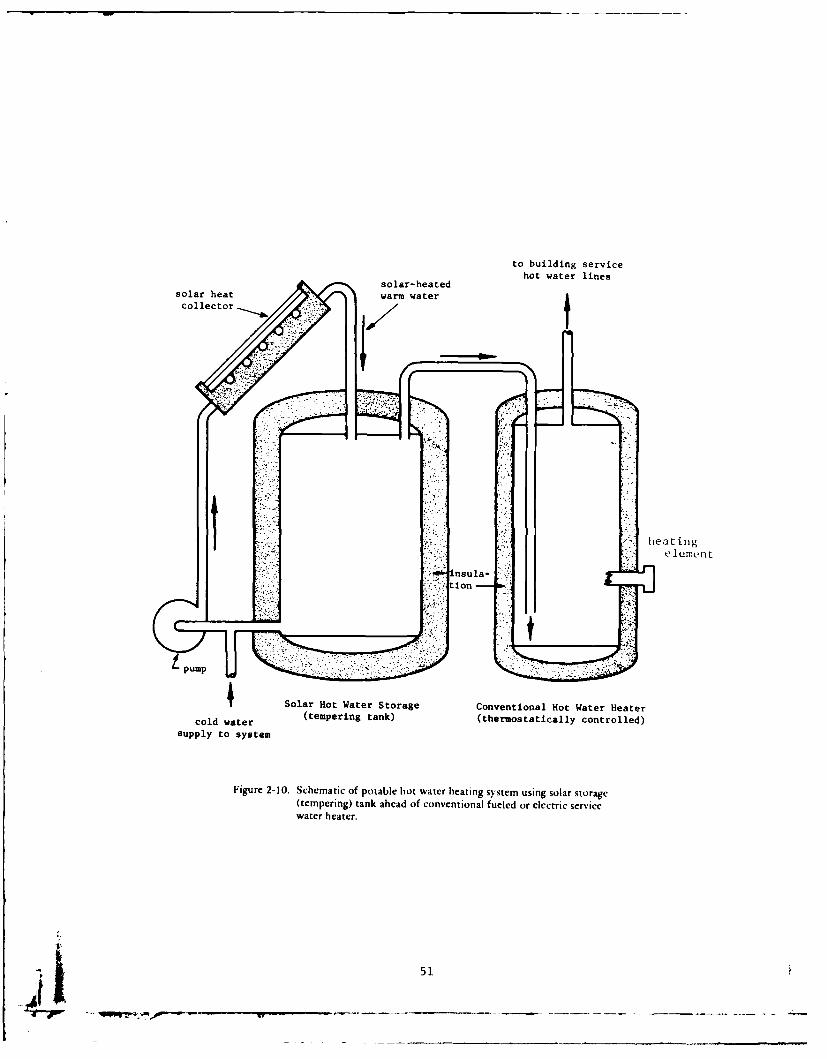
to building servicehot water lines
solar-heatedsolar heat warm watercollector
heat ing
element;&insula-
! t ion -
Solar Hot Water Storage Conventional Hot Water Heater
cold water (tempering tank) (thermostatically controlled)
supply to system
Figure 2-10. Schematic of potable hot water heating system using solar storage(tempering) tank ahead of conventional fueled or electric servicewater heater.
_j 51
The advantage of latent heat storage is that it can store very
large quantities of het-n per pound of storage material. Therefore, less
volume should be reQuired for latent heat storage than for heat storage
in rock beds. However, problems of slow solidification and low heat
conductivity retards effective heat transfer to and from the material.
As a result, a large surface area-to-volume ratio is required, which
significantly increases the effective volume of latent storage.
Storage materials used are often expensive when compared to rook.
In addition, they must be packaged in individual containers to allow
adequate heat transfer area. Many latent heat materials cannot with-
stand frequent recycling and must be replaced periodically. Research
is being done by CEI. and others to develop practical latent heat mate-
rials which can withstand extended recycling. CEL is investigating a
dissolved salt storage unit that uses immiscible liquids for the heat
exchange surface which greatly reduces the problem of crystallization
during recycling. Initial tests have been encouraging.
Another major drawback of latent heat storage is that heat is
stored at an average temperature with essentially no thermal stratifica-
tion occurring in Ihe storage unit. A high level of thermal stratifica-
tion maximizes thermal performance because low temperature fluid can be
delivered to the collectors and high temperature fluid can be delivered
to the heat load. For example, the high degree of thermal stratification
in rock-beds results in the delivery of 79 0 F air to the collector and
1201F to 150'F air to the heat load. In comparison, latent heat storage
in Glauber's salt occurs near an average .temperature of 90'F; thus air
at 90OF is delivered to both the collectors and the heat load.
Due to the problems discussed, 'latent heat storage has not
received widespread use.
Since it is not economically justifiable to store huge quantities of
heat, most solar systems cannot be depended on to provide 100% of the
buildings needs. Depending on the geographical area and size of the
system, about 40%o to 80% of the heat requirement is the average to
design for. Therefore auxiliary heaters are necessary. They should
52
- ______-.~
be sized to provide all the energy requirements. although in some
cases, again depending on location, it may be possible to increase
storage volume and provide less than 100% backup auxiliary heat. This
is especially true if the use of passive solar (h'signs can be incor-
porated with active systems. Passive designs are discussed briefly in
Section 2.6.The auxiliary heater should operate automalically as needed, use
the most economical fuel, and share a common heat delivery system with
the solar system. Often a heat pump is a good choice in that it can
serve both as an auxiliary heater and work together with the solar
system. In retrofit situations, the existing heater would be the choice.
2.2.1 Storage Tanks. Water may be stored in a variety of con-
tainers usually made of steel, concrete, plastics, fiberglass, or other
suitable materials.
Steel tanks are commercially available and have been used for'
water storage. They are available in many sizes and are relatively easy
to install. However, steel tanks are susceptible to corrosion and should
be lined or galvanized. Dissimilar metal at pipe connections should be
separated by high temperature rubber connections or galvanic corrosion
will occur. Steel tanks must be well insulated to minimize heat losses.
Concrete tanks are durable, but may be difficult to install. Con-
crete tanks cast in place, prefabricated septic tanks, or large diameter
pipes may be used for water storage. A high temperature sealant or
lining should be applied to the interior of the tank to prevent seepage
of water through the tank. Although concrete is less conductive than
steel, concrete tanks should also be insulated to reduce thermal losses.
Leaks are difficult to repair.
Fiberglass and plastic tanks are corrosion resistant and easily
installed. They are available in many shapes and sizes. Although
many commonly fabricated tanks will begin to soften at temperatures
above 140'-160*F, there are more expensive, specially fabricated tanks
available that can withstand temperatures up to 2501F. The types of
plastics needed to store large quantities of water at high temperatures
can be more expensive than steel.
53
When storage tanks are to be custom made, a calculation of heatloss against expected fuel cost inflation will almost always justify in-creasing insulation around the tank to R-19, 6 inches, compared withthe usual 2 inches. HUD Intermediate Minimum Property Standards(U.S. Dept HUD, 1977) requires that tank losses be limited to 10% in 24hours. Usually R-19 insulation will satisfy this requirement.
L-osts of storage tanks vary considerably depending on the qualityof construction and the distributor. Table 2-7 summarizes advantagesand disadvantages and Table 2-8 gives approximate comparative costsfor tanks of various materials. All storage tanks for liquids should belocated so that if they leak, damage to the building will be prevented.The cost of housing the tank or burying it must be included in thetotal cost of the solar heating system. Buried tanks must be protectedfrom ground water, and buoyant forces resisted. Tank must be reason-ably accessible for repairs. In very mild or warm climates, outdoorlocation may be feasible.
2.3 Domestic Hot Water Systems (DHW)
Domestic hot water systems (without space heating) may use lined,insulated, pressurized tanks similar to the conventional water heater.Appropriate temperature and pressure relief valves must be used.Since it is possible for solar collectors to reach very hot temperatures,a tempering or mixing valve should be used. A typical two-tank instal-lation with proper valves and connections would be as shown in Figure2-11 (Cole et al., 1979).
To size the collectors and storage tank it is necessary to estimateor measure the hot water consumption of the facility or building. Fortypical family residences, 20 gal/day/person of hot water is normallyconsumed. If it is estimated the hot water consumption is larger thanaverage, use 30 gal/day/person. So, 80 to 120 gal/day should serve atypical four-person family. For estimates of other facilities refer toTable 2-9, which gives water consumption for many kinds of facilities(Werden and Spielvogel, 1969). Although these are for conventionalfacilities, they should provide a reasonable estimate of Navy facilities(barracks, etc.) for lack of any better data.
54
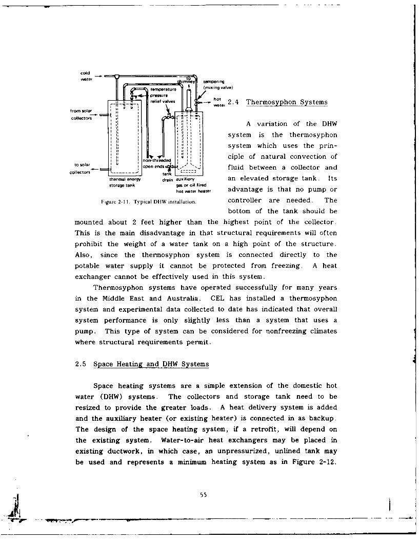
coldater Imney tempering
temperature (mixing valve)
- pressure hotrelief valves ht
colletrwater 2.4 Thermosyphon Systems
colector, f - -.
A variation of the DHW
system is the thermosyphon
,I system which uses the prin-
,, ,nrZh;Jd U, ciple of natural convection oft UI II Ito solaro pen ends fluid between a collector and
collectors ---- - - tank ------. -
thermalenergy drain auxiliary an elevated storage tank. Itsstorage tank gas or oil fired
hot water heater advantage is that no pump or
Figure 2-11. Typical DIIW installation. controller are needed. The
bottom of the tank should be
mounted about 2 feet higher than the highest point of the collector.
This is the main disadvantage in that structural requirements will often
prohibit the weight of a water tank on a high point of the structure.
Also, since the thermosyphon system is connected directly to the
potable water supply it cannot be protected from freezing. A heat
exchanger cannot be effectively used in this system.
Thermosyphon systems have operated successfully for many years
in the Middle East and Australia. CEL has installed a thermosyphon
system and experimental data collected to date has indicated that overall
system performance is only slightly less than a system that uses a
pump. This type of system can be considered for nonfreezing climates
where structural requirements permit.
2.5 Space Heating and DHW Systems
Space heating systems are a simple extension of the domestic hot
water (DHW) systems. The collectors and storage tank need to be
resized to provide the greater loads. A heat delivery system is added
and the auxiliary heater (or existing heater) is connected in as backup.
The design of the space heating system, if a retrofit, will depend on
the existing system. Water-to-air heat exchangers may be placed in
existing ductwork, in which case, an unpressurized, unlined tank may
be used and represents a minimum heating system as in Figure 2-12.
55
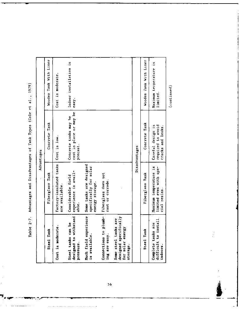
a; W
".-4
00 >1m 0 n " 4 0a x
J4 Jig:
0V 00V O
- -4,q -
0~~ 0~0
(V 0 C~ dI~0 10 00 0A 4 . 0( :: 4 wV
4) fn4) u w t0 to S. M.
o) m 4)c m a
-X >>
.1 a) C)2"C U4 '4 1
W cc 4-1 -4 0 4) > 3c4.) 4) 4 m m " 40
$4 ,40- 14m44 ( u.. 5W 4 W00 1) -4 C.4 0 93u
m 1 4) a2 M - -
o1 -4 4 10 4 4J 400> 0c 042 W0040 w(24 4 4) 14. 41 ) 0d$ 0C0 41 (4 H 4
4> (V P. 4 6 -tcc w 0n 'V a .c ,
a~~- 2( 4-4
(V. 4)- *r 4 4.) .4 4(4 ' 4 Z 4) m4) 0 2 1
43 4) .)> '4 Q E- 4 41)4) 0C 14)( 4'V (12 C4J * 4 1 ).4 J' 4 .
cc U) -44 0) C: 00 00 4$4 CV 3t 4)- (a.C 'V1 4)
(a 01. 4 -4 G ( 0 4) m 24104 0 AdV .41) V ) a 0 001- a . 4 >m) 14 1-4 toI. X( 4. (4 ) 14 .41
4) to PC 4 ) 4) -1 -4 4)* M -4 4 -4J41) go 4 1.0 wV- 4 .,q- 41000-44 1 41:
07 rq OV *1 4 m'40 1 4 0 2 ow 4)vw4V4 44) 4 F 4 m U 4 4 -H -0(A 4 ) 4) u- I44 .(A aw0 42
0 (.1 4)$ 30 0 93 4) 0410 ,4
V) U) .14 M. V-> 44 CA
-4 X ) 04 4) M4-0 .56
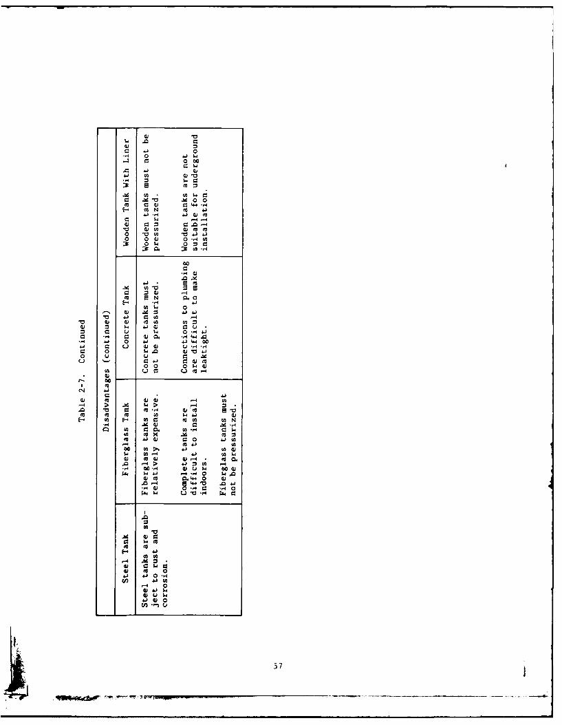
4.0 0414 0
0 0C
4.
0. 0 ) t
m SN 0
C $ -4 4j,4 ~ G 41 0 4.)4J 4 0
o 0 0 w d)
00.
44 G
M -4 cum"
, -4 %d : -
M~ 4-) W -r4 C
m 41 4) 0Ci Ai t
4 ~ $.4 44)- 41 oW m (U ( 4
.0 *-4 > :3Q W4.4.'-4 4.1 0 w~ 4.L.0
13 4-4 4)4C~~ 0M 0.. 4'
Cl) C C : C.(cc- 0
4. 4.)H
~ 4 4)
(C ' (C ) 14.)57
.Chw, WT' p)C lo C)) oN
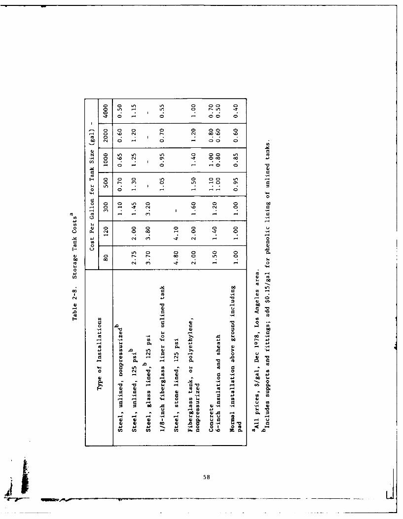
o V) -it r- Ln ~ -
cc 0- 1 0 - 0 00 0 l
.- 0 0 0a 0 0'
., 0 \.0 04- 000. '00n 0
00 0 0 -' 00 0l
0 0 I t 0 0 t
CO 0 00 0 0 -. 0 0 0 '0
-~ C4
0-
0 4 0 0 0 U'0 00 u-
u 04 14' a 0 CD -t .,
4-4 4.4l C4
0 0
0) r- - r)- 00 0 0
m. 0.. N 0CO-4 0 - 0 .
-4 . m 4.n 4W ' -
0 00
0.0
00 CO . . 0
0. 4.V0 --
COV ' 00 9 C
004 (U j 0411- 0 (A -mI , .0-,-4 00 r
ca 41 m. 0 -4041~~~~4 to .) w 1 .
C: ) 00" w I
0 - -4 10 Q 0(A4 .4 cc
0 0) C1 V0V4) 00l., o 4
C: ' 1-4 0 0 o $0 N-.4# 00 .. q hd4 CO m'-44 -'4(A 4 1-4 C.0 -1 00 0). 4.
1.4 (A 4) w 0-4AA 4) 4-1 N) -4 cc
.14( -,4 N 0 ., 9 .4 ( 0 41WU
- 1-4 - o -4 .' w. (a ca W
6440 W to . A H. 0 4 0 ,0 -4 W) 01 4) 0 '.
C3. 00 4'. w~ '4 0. :0V4 -4 1.4 1-4 $4 $ $4. V 4 ~ ~~-' 4) 4) 0)4) 0 -4 :
0) 0 ( 4) 4 -4 0 93"4r4 9'4 '4 41 -'. .4 0 0 0 0 C
to0 0nE z 0 4 (
00.0 (A (A )-H584
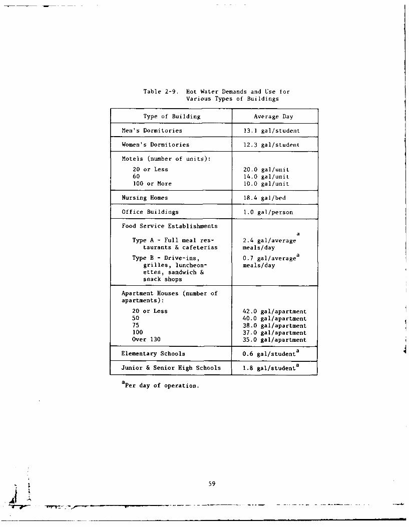
Table 2-9. Hot Water Demands and Use forVarious Types of Buildings
Type of Building Average Day
Men's Dormitories 13.1 gal/student
Women's Dormitories 12.3 gal/student
Motels (number of units):
20 or Less 20.0 gal/unit60 14.0 gal/unit100 or More 10.0 gal/unit
Nursing Homes 18.4 gal/bed
Office Buildings 1.0 gal/person
Food Service Establishmentsa
Type A - Full meal res- 2.4 gal/averagetaurants & cafeterias meals/day
Type B - Drive-ins, 0.7 gal/averagea
grilles, luncheon- meals/dayettes, sandwich &snack shops
Apartment Houses (number ofapartments):
20 or Less 42.0 gal/apartment50 40.0 gal/apartment75 38.0 gal/apartment100 37.0 gal/apartmentOver 130 35.0 gal/apartment
Elementary Schools 0.6 gal/student a
Junior & Senior High Schools 1.8 gal/studenta
a Per day of operation.
59
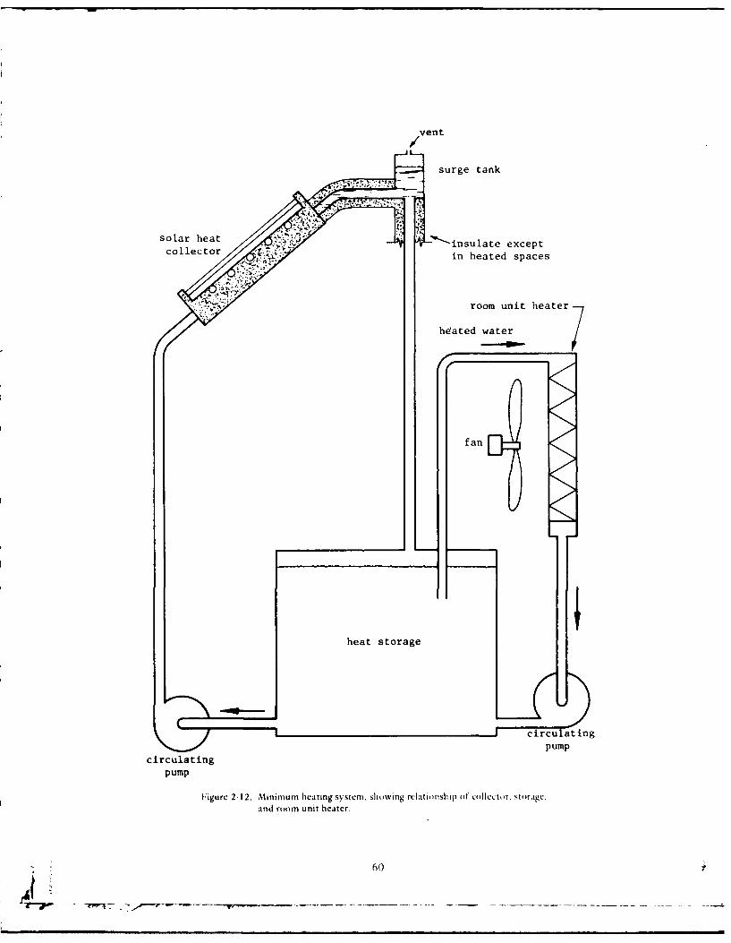
surge tank
solar heatcollecor _:_insulate except
in heated spaces
room unit heater
hdated water7
fan
heat storage
circulating
circulating PUMP
pump
1Figurc 2-12. Mtinimum heating system, showing relationship ot* collector, storage.and room unit heater.
60)
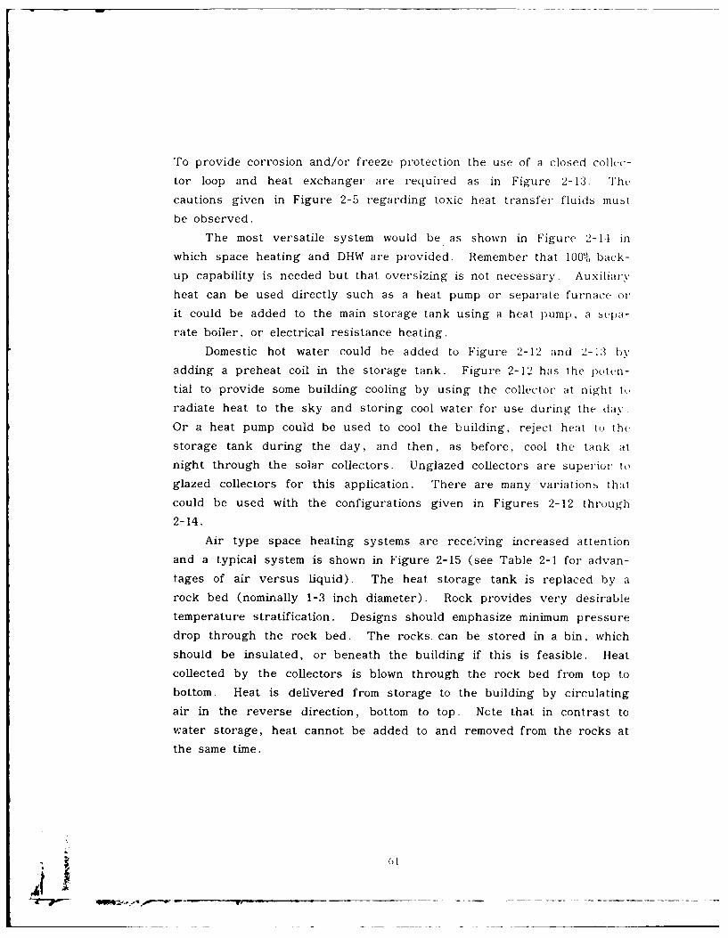
To provide corrosion and/or freeze protection the use of a closed collcc-
tor loop and heat exchanger are required as in Figure 2- 13. Th e
cautions given in Figure 2-5 regarding toxic heat transfer fluids mut
be observed.
The most versatile system would be 'as shown in Figure 2-14 in
which space heating and DHW are provided. Remember that 100% back-
up capability is needed but that oversizing is not necessary. Auxiliarx,
heat can be used directly such as a heat pump or separate furnace or
it could be added to the main storage tank using a heat pump, a bepa-
rate boiler, or electrical resistance heating.
Domestic hot water could be added to Figure 2-12 and 2-13 by
adding a preheat coil in the storage tank. Figure 2-12 has the p)oten-
tial to provide some building cooling by using the collector at night to
radiate heat to the sky and storing cool water for use during the day.
Or a heat pump could be used to cool the building, reject heat to thc
storage tank during the day, and then, as before, cool the tank at
night through the solar collectors. Unglazed collectors are superior to
glazed collectors for this application. There are many variations thait
could be used with the configurations given in Figures 2-12 through
2-14.
Air type space heating systems are receiving increased attention
and a typical system is shown in Figure 2-15 (see Table 2-1 for advan-
tages of air versus liquid). The heat storage tank is replaced by a
rock bed (nominally 1-3 inch diameter). Rock provides very desirable
temperature stratification. Designs should emphasize minimum pressure
drop through the rock bed. The rocks. can be stored in a bin, which
should be insulated, or beneath the building if this is feasible. Heat
collected by the collectors is blown through the rock bed from top to
bottom. Heat is delivered from storage to the building by circulating
air in the reverse direction, bottom to top. Ncte that in contrast to
water storage, heat cannot be added to and removed from the rocks at
the same time.
01
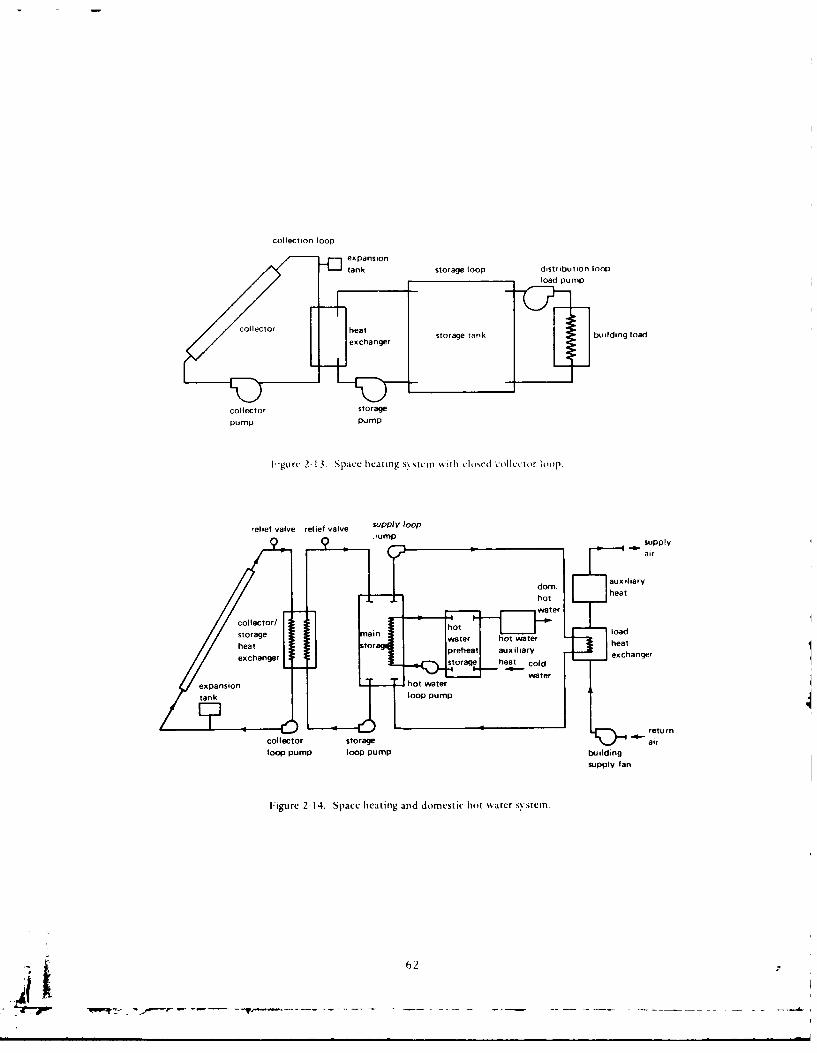
collection loop
tank storage loop distribution loopload pump
colco etstorage tank building load
collector storagepump PUMP
F igurv 2-13. Space hecating sys tcm with cIliscd collecetor liiip
relief valve relief valve supyJ0.,umpsupply
air
collector/ ho6I2
/ / Iblower
/Z'-/ L Icold waterZo°'7( ifmain
load
df to buildingJ heatingiload
m rblowerair plenum
flur pebb le-bed
storage
plenum
mt r s T return air
i smo i te from buildingdampers
Figure 2-15. b pical air-type space heating sstem.
During heat collection, the rocks at the top of the bin will attain a
temperature nearly equal to that of the incoming solar heated air, while
the air leaving the storage will be delivered to the collectors at theminimum temperature of the rocks. The conduction between the rocks
is small, thus with no air circulation the rock bed will remain stratified
with the top of the rock bed warmer than the bottom. Also, limitedconduction and convection in the rock-bed significantly reduces heat
loss from the rock-bed.
Heat is drawn from the storage by circulating building air directly
through the rock bed from bottom to top. The air will then be deliv-
ered to the building at a temperature near the maximum temperature of
the collectors. If additional heat is required, supplementary heat is
added down-stream from the storage unit. This system allows the rock
bed to deliver us,,ul heat until all of the rocks are at room tempera-
ture. See Duffie and Beckman (1974) for design of packed bed rock
storage.
63
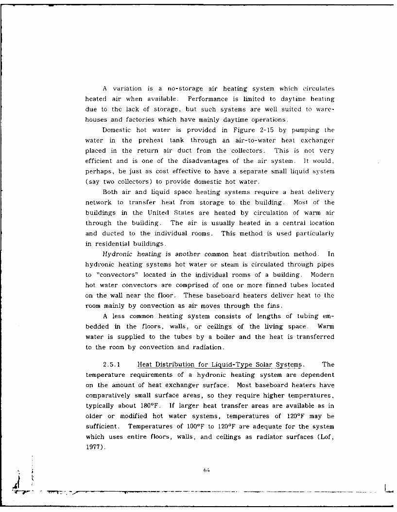
A variation is a no-storage air heating system which circulates
heated air when available. Performance is limited to daytime heating
due to the lack of storage, but such systems are well suited to ware-
houses and factories which have mainly daytime operations.
Domestic hot water is provided in Figure 2-15 by pumping the
water in the preheat tank through an air-to-water heat exchanger
placed in the return air duct from the collectors. This is not very
efficient and is one of the disadvantages of the air system. It would,
perhaps, be just as cost effective to have a separate small liquid system
(say two collectors) to provide domestic hot water.
Both air and liquid space heating systems require a heat delivery
network to transfer heat from storage to the building. Most of the
buildings in the United States are heated by circulation of warm air
through the building. The air is usually heated in a central location
and ducted to the individual rooms. This method is used particularly
in residential buildings.
Hydronic heating is another common heat distribution method. In
hydronic heating systems hot water or steam is circulated through pipes
to "convectors" located in the individual rooms of a building. Modern
hot water convectors are comprised of one or more finned tubes located
on the wall near the floor. These baseboard heaters deliver heat to the
room mainly by convection as air moves through the fins.
A less common heating system consists of lengths of tubing em-
bedded in the floors, walls, or ceilings of the living space. Warm
water is supplied to the tubes by a boiler and the heat is transferred
to the room by convection and radiation.
2.5.1 Heat Distribution for Liquid-Type Solar Systems. The
temperature requirements of a hydronic heating system are dependent
on the amount of heat exchanger surface. Most baseboard heaters have
comparatively small surface areas, so they require higher temperatures,
typically about 180'F. If larger heat transfer areas are available as in
older or modified hot water systems, temperatures of 1201F may be
sufficient. Temperatures of 1001F to 1201F are adequate for the system
which uses entire floors, walls, and ceilings as radiator surfaces (Lof,
1977).
64
V.- _ _ __ --
During the winter, typical liquid-type solar systems are seldom
operated at delivery temperatures above 1501F. Thus it is evident that
the use of solar heated water in standard baseboard heaters is imprac-
tical. Only modified baseboard heaters of adequate size or radiant
panels are suitable for use in hydronic systems which use solar heated
water.
One of the most
economical means of
flow auxiliary heat supply
furnae and heat distribution
for liquid-type solarsolar systems involves thestorage
use of a warm air
system. A typicalosystem is illustrated in
low Figure 2-16. In this
liquid to air- system the warm air
return heater furnace is located down-exchanger
stream from a liquid-to-Iigurc 2-16. A liquid-to-air heat deliverN systcm, air heat exchanger
which is supplied with
solar-heated water. The furnace can then serve to boost air tempera-
ture when insufficient heat is available from the solar heated water, or
it can meet the full heat load if no heat is available in solar storage.
Auxiliary heat can be supplied by a gas, oil, or electric furnace, or by
the condenser of an air-to-air heat pump.
Another method of heat distribution involves the use of a water-
to-air heat pump which draws heat from the solar storage tank and
pumps it to a condenser coil which is placed in a central air duct. The
advantage of this system is that it can effectively use heat from solar
storage at temperatures down to 45°F, thus more of the stored heat is
available. Also, average storage temperatures are lower, resulting in
significantly increased collector efficiency. Heat pumps are discussed
in Section 2.5.3.
65
2.5.2 Heat Distribution for Air-Type Solar Systems. The pipes
and pumps of the liquid-type system are replaced by air ducts and
fans. The warm air system is obviously the best heat distribution
system for use with an air-type solar system. The ability to circulate
building air directly through the collectors is one of the major advan-
tages of an air-type solar system. The rock bed storage also works
best with a warm air system.
Although warm air as low as 1001F can be used to heat an occu-
pied building, most existing warm air systems are sized assuming warm
air temperatures of 120'F to 150'F. Typical mid-day collection tempera-
tures usually range from 130OF to 1701F. Maximum storage tempera-
tures are typically around 140'F at the end of the collection period.
Thus the heating load can be met by the temperature of the solar
heated air a large portion of the day. When storage temperatures are
insufficient to maintain the desired temperature in the building, heat
from an auxiliary source must be added to supplement the solar heated
that the rock bed serves as a preheater for the furnace. This arrange-
ment allows the rock bed to deliver useful heat until all of the rocks
are at room temperature.
An air handler unit provides the dampers and blowers necessary to
direct air circulation between the solar collectors, rock-bed, and build-
ing as needed. An air handler unit may be more expensive than the
combined cost of individual dampers and blowers, but it will probably
be less expensive to install. It is also more compact.
2.5.3 Heat Pumps. Heat pumps have been mentioned in previous
sections as a possible choice for auxiliary heaters. Some manufacturers
are combining solar systems with heat pumps for the purpose of reduc-
ing auxiliary energy costs. When a heat pump and a solar system are
combined in this manner, the system is usually called a solar assisted
or solar augmented heat pump (SAHP) system.
Solar assisted heat pump systems can be configured in many dif-
ferent ways. For example, the solar collectors can be either water or
air types, the heat storage medium can be water or a solid material
* 66j
such as rock or brick, and the heat pump can be of either the air-to-
air design or the water-to-air design. But heat pumps have a charac-
teristic which can limit their effectiveness: the efficiency and capacity
of a heat pump decreases as the temperature of the heat source
(usually outdoor air) decreases. This deficiency can be overcome,
however, by using solar collectors to gather the sun's energy for the
purpose of keeping the heat source in the temperature range required
for efficient heat pump operation.
Air-to-Air Heat Pumps - The air-to-air heat pump functions verywell as an auxiliary heater at temperatures down to 20'F.
Below these temperatures, it suffers in efficiency and perfor-
mance. When solar assisted by heat from a rock-pebble
storage bed and air collectors, the heat pump adds much to
the performance of the solar energy system.
Without such a solar assist, air-to-air heat pumps have
limited utility in cold climates. Their use should be carefullychecked with the local utility and pump manufacturer.
The heat pump also provides cooling during the summer.
It thus has year-round utility. Heat pumps should be
comparison- shopped. The purchaser should look at the cost,
performance, service, and expected life. Units differ consid-erably from manufacturer to manufacturer. (Montgomery,
1978).
Liquid-to-Air Heat Pumps - The liquid-to-air heat pump is an ideal
auxiliary heater when coupled with liquid solar storage. It
operates at very low cost. And it greatly enhances solar
energy collection by drawing down the temperature of the
solar storage water to as low as 45'F. It should be con sid-ered for all installations, except those with existing fossil fuel
furnaces and no need for summer cooling. (Montgomery,
1978).
67
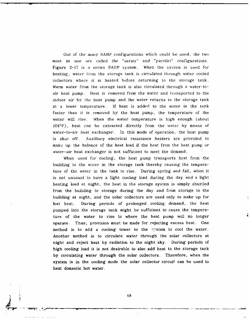
Out of the inany SAUP configurations which could be used, the two
most in use are called the "series" and "parallel" configurations.
Figure 2-17 is a series SAIIP system. When the system is used for
heating, water friom the storage tank is circulated through water cooled
collectors where it is heated before returning to the storage tank.
Warm water from the storage tank is also circulated through a water-to-
air heat pump. Heat is removed from the water and transported to the
indoor air by the heat pump and the water returns to the storage tank
at a lower temperature. If heat is added to the water in the tank
faster than it is removed by the heat pump, the temperature of the
water will rise. When the water temperature is high enough (about
1041F), heat can be extracted directly from the water by means of
water-to-air heat exchanger. In this mode of operation, the heat pump
is shut off. Auxiliary electrical resistance heaters are provided to
make up the balance of the heat load if the heat from the heat pump or
water-air heat exchanger is not sufficient to meet the demand.
When used for cooling, the heat pump transports heat f rom the
building to the water in the storage tank thereby causing the tempera-
ture of the water in the tank to rise. During spring and fall, when it
is not unusual to have a light cooling load during the day and a light
heating load at night, the heat in the storage system is simply shuttled
from the building to storage during the day and from storage to the
building at night, and the solar collectors are used only to make up for
lost heat. During periods of prolonged cooling demand, the heat
pumped into the storage tank might be sufficient to cause the tempera-
ture of the water to rise to where the heat pump will no longer
operate. Thus, provision must be made for rejecting excess heat. One
method is to add a cooling tower to the -:,stem to cool the water.
Another method is to circulate water through the solar collectors at
night and reject heat by radiation to the night sky. During periods of
high cooling load it is not desirable to also add heat to the storage tank
by circulating water through the solar collectors. Therefore, when the
system is in the cooling mode the solar collector circuit can be used to
heat domestic hot water.
68
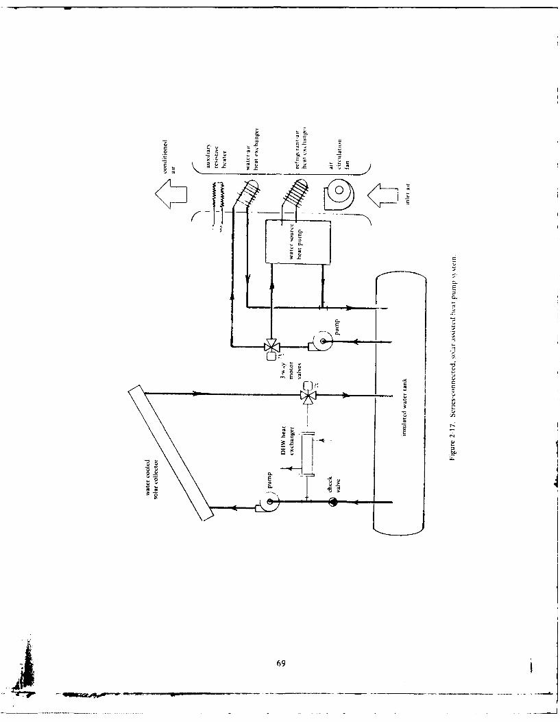
9 E
4,t4
CL-
69 -
The "parallel" SAHP system is shown in Figure 2-18. The solar
heating system and the heat pump operate in parallel. Solar heat is
used directly rather than being transferred to a storage medium and
then transported into the building with a heat pump. This systein is
essentially a direct solar heating system with an air-to-air heat pump as
a backup heating system.
The choice of a "best" system is difficult to make due to the many
variables involved. For example, in addition to the two configurations
shown in Figures 2-17 and 2-18, one could examine a series system with
low cost (unglazed) collectors, or a series system with air-collectors
and rock storage, or a parallel system with low cost collectors, etc.
Each system would be highly dependent on geographical location, type
of construction, etc. One such analysis done at CEL comparing several
systems to a stand-alone air source heat pump, showed the "parallel"
system to have the best comparative performance (Kirts, 1978). More
information about heat pump systems can be found in Kirts (1978).
Each heat pump configuration should be considered on a case-by-
case basis. The analysis of these systems is beyond the scope of the
worksheets given in this report, and the reader is directed to more
sophisticated computer programs such as those in Durlak (1979b).
2.6 Passive System,.
A "passive" solar energy system is one which uses the building
structure as a collector, storage and transfer mechanism with a minimum
amount of mechanical equipment. Some would include a thermosyphon
system in this definition. As a rule, these systems are generally
difficult to retrofit. Another disadvantage is that the owner or occu-
pant may be required to perform daily tasks, such as covering a south
facing window at night, opening and closing shutters, etc. This is
particularly significant in Navy housing where the occupants are more
transient and have less incentive to do these maintenance items.
Although the specific arrangements vary, all of these systems rely on
direct solar heating of storage. The storage then heats the house. A
few examples are shown in Figure 2-19 (Barnaby et al. , 1977).
70
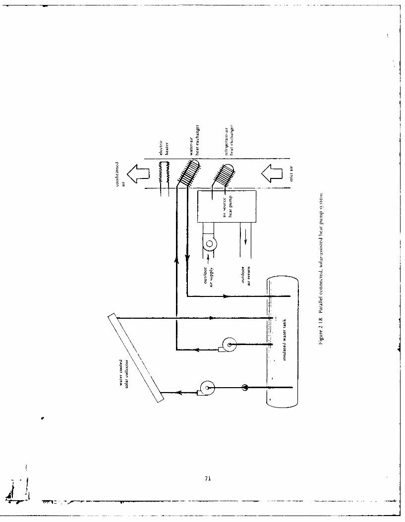
- Vt
-~K~z4I! _ _K'I
0
V.1
0--~
00S 0OV-
Vt CVt C
U
.q.I cc
IN
4.. U
Vt 0
~0
0
~
pVt n
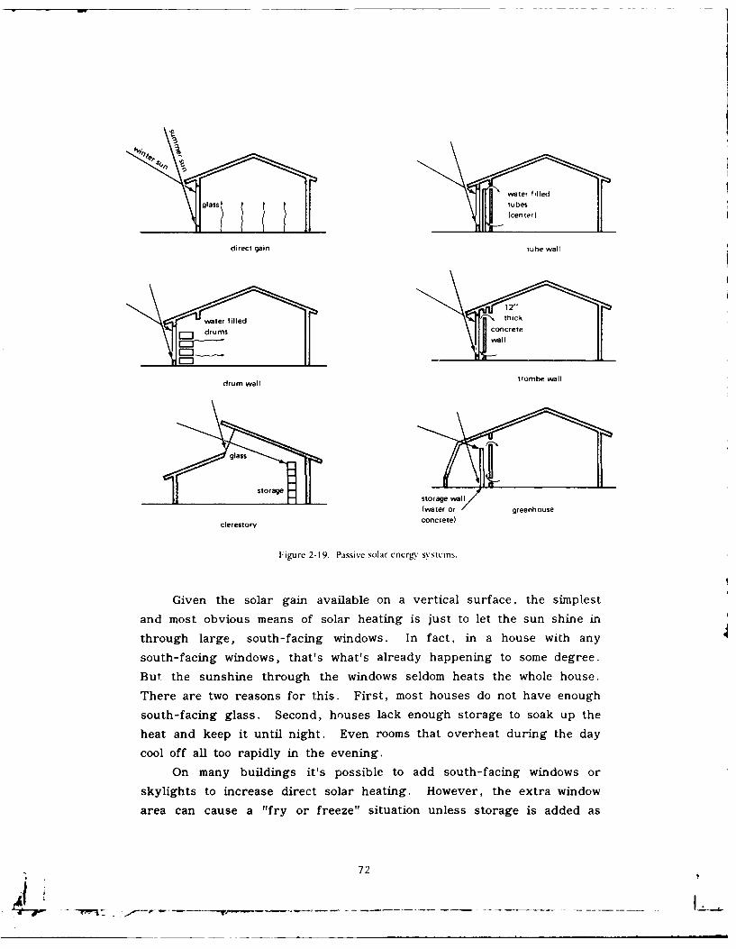
water frlledglass$ tu besH (center)
direct gain tube wall
12"
water filled thick
drums concretegwall
drum wall trombe wall
glass
storagestorage wal(water oa greenhouse
clerestory concrete)
Figure 2-19. Passive solar encrgy systems.
Given the solar gain available on a vertical surface, the simplest
and most obvious means of solar heating is just to let the sun shine in
through large, south-facing windows. In fact, in a house with any
south-facing windows, that's what's already happening to some degree.
But the sunshine through the windows seldom heats the whole house.
There are two reasons for this. First, most houses do not have enough
south-facing glass. Second, houses lack enough storage to soak up the
heat and keep it until night. Even rooms that overheat during the day
cool off all too rapidly in the evening.
On many buildings it's possible to add south-facing windows or
skylights to increase direct solar heating. However, the extra window
area can cause a "fry or freeze" situation unless storage is added as
72
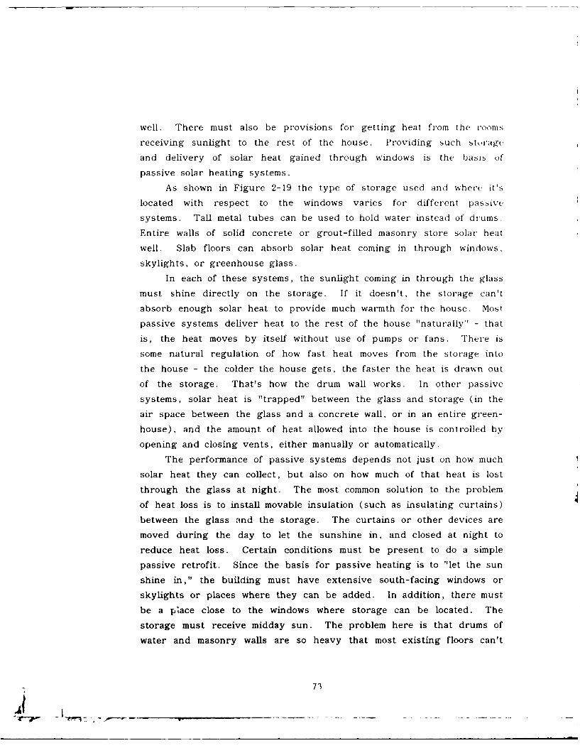
well. There must also be provisions for getting heat from the rooms
receiving sunlight to the rest of the house. Providing such storage
and delivery of solar heat gained through windows is the basis of
passive solar heating systems.
As shown in Figure 2-19 the type of storage used and where it's
located with respect to the windows varies for different passive
systems. Tall metal tubes can be used to hold water instead of drums.
Entire walls of solid concrete or grout-filled masonry store solar heat
well. Slab floors can absorb solar heat coming in through windows,
skylights, or greenhouse glass.
In each of these systems, the sunlight coming in through the glass
must shine directly on the storage. If it doesn't, the storage can'
absorb enough solar heat to provide much warmth for the house. Most
passive systems deliver heat to the rest of the house "naturally' - that
is, the heat moves by itself without use of pumps or fans. There is
some natural regulation of how fast heat moves from the storage into
the house - the colder the house gets, the faster the heat is drawn out
of the storage. That's how the drum wall works. In other passive
systems, solar heat is "trapped" between the glass and storage (in the
air space between the glass and a concrete wall, or in an entire green-
house), and the amount of heat allowed into the house is controlled by
opening and closing vents, either manually or automatically.
The performance of passive systems depends not just on how much
solar heat they can collect, but also on how much of that heat is lost
through the glass at night. The most common solution to the problem
of heat loss is to install movable insulation (such as insulating curtains)
between the glass and the storage. The curtains or other devices are
moved during the day to let the sunshine in, and closed at night to
reduce heat loss. Certain conditions must be present to do a simple
passive retrofit. Since the basis for passive heating is to "let the sun
shine in," the building must have extensive south-facing windows or
skylights or places where they can be added. In addition, there must
be a place close to the windows where storage can be located. The
storage must receive midday sun. The problem here is that drums of
water and masonry walls are so heavy that most existing floors can't
73
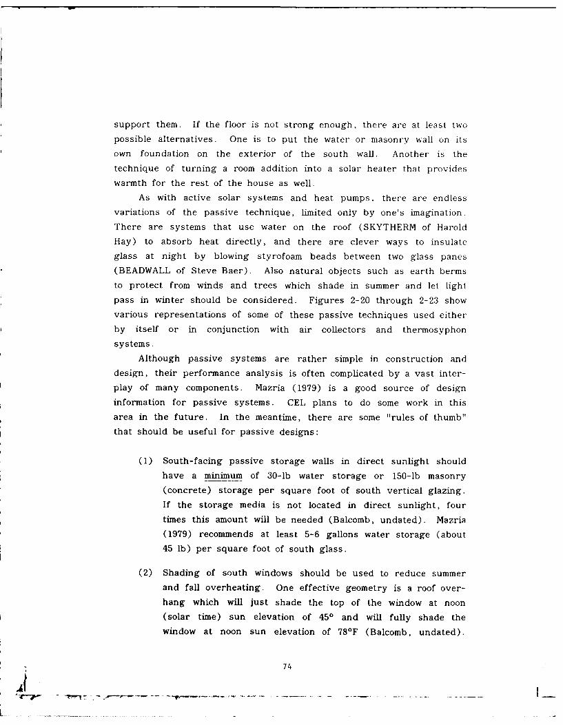
support them. If the floor is not strong enough, there are at least two
possible alternatives. One is to put the water or masonry wall on its
own foundation on the exterior of the south wall. Another is the
technique of turning a room addition into a solar heater that provides
warmth for the rest of the house as well.
As with active solar systems and heat pumps, there are endless
variations of the passive technique, limited only by one's imagination.
There are systems that use water on the roof (SKYTHERM of Harold
Hay) to absorb heat directly, and there are clever ways to insulate
glass at night by blowing styrofoam beads between two glass panes
(BEADWALL of Steve Baer). Also natural objects such as earth berms
to protect from winds and trees which shade in summer and let light
pass in winter should be considered. Figures 2-20 through 2-23 show
various representations of some of these passive techniques used either
by itself or in conjunction with air collectors and thermosyphon
systems.
Although passive systems are rather simple in construction and
design, their performance analysis is often complicated by a vast inter-
play of many components. Mazria (1979) is a good source of design
information for passive systems. CEL plans to do some work in this
area in the future. In the meantime, there are some "rules of thumb"
that should be useful for passive designs:
(1) South-facing passive storage walls in direct sunlight should
have a minimum of 30-lb water storage or 150-lb masonry
(concrete) storage per square foot of south vertical glazing.
If the storage media is not located in direct sunlight, four
times this amount will be needed (Balcomb, undated). Mazria
(1979) recommends at least 5-6 gallons water storage (about
45 lb) per square foot of south glass.
(2) Shading of south windows should be used to reduce summer
and fall overheating. One effective geometry is a roof over-
hang which will just shade the top of the window at noon
(solar time) sun elevation of 450 and will fully shade the
window at noon sun elevation of 781F (Balcomb, undated).
74
-- '- - L _ _ V
N,,A corrrrrrctio ttI,-
Alpp~oa ch
91 ISS S II CilfrttriOLIS used darien do,, iilv
naturaI~l (coneti
Ad: "Ir sages
Op ll r e rr ir s' r i
Os 0 Simple, rio moviri pa',lailack corrugarod! steel sipiricrrl & Etfecivc rrdeir crintal.
convector rjiqht r
ODEILLO OFFICE (FRANCEI
South wall
Figure 2-20. NcN%-cornstruction (office) pasne solar cncrgv sv stein.
Thermosyphon OHW System
sivrs- .iclr right -aviid dl'I
urnmin Ar4.is iiti-
Summer
vin tel
Figure 2-2 1. Vertical wail solar collector.
75
7~*,

Tt
.4.
f- f
P-'TV Il ", 11, r V
igr, -2' k il ,hr ,.lcto wih ib nc T,.rii.
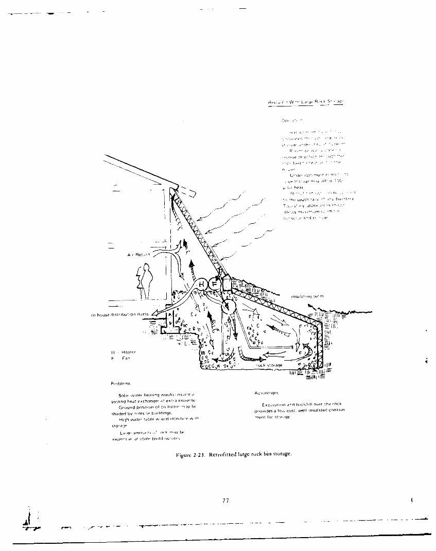
Rrrro F L 0' 91q R, ST 1 0
Do.
,.~./ 7n~ssouth 'A
-- S!I~ pp c, Int~ h)
H , Reta r
GOh uedsr on d cso fcletrmyS ea trrladb kfl a'herk
Problems
Slar. ,rVT urf rfain ol r e luv I Seifae
GXJ.roundr pit io of0f' Coi llecto ma wE cjT'inad akilovrTe
F~igure 2-2 3. Retrofitted large rock bin storage.
77
.Att- --
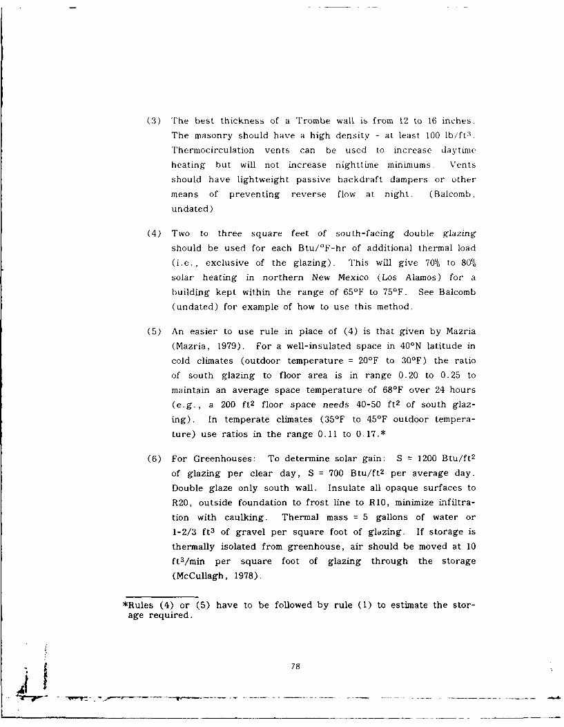
(3) The best thickness of a Trombe wall is from 12 to 16 inches.
The masonry should have a high density - at least 100 lb/ft 3 .
Thermocirculation vents can be used to increase daytime
heating but will not increase nighttime minimums. Vents
should have lightweight passive backdraft dampers or other
means of preventing reverse flow at night. (Balcomb,
undated)
(4) Two to three square feet of south-facing double glazing
should be used for each Btu/°F-hr of additional thermal load
(i.e., exclusive of the glazing). This will give 70% to 80%
solar heating in northern New Mexico (Los Alamos) for a
building kept within the range of 65°F to 75°F. See Balcomb
(undated) for example of how to use this method.
(5) An easier to use rule in place of (4) is that given by Mazria
(Mazria, 1979). For a well-insulated space in 401N latitude in
cold climates (outdoor temperature = 20'F to 301F) the ratio
of south glazing to floor area is in range 0.20 to 0.25 to
maintain an average space temperature of 68'F over 24 hours
(e.g., a 200 ft 2 floor space needs 40-50 ft2 of south glaz-
ing). In temperate climates (35°F to 451F outdoor tempera-
ture) use ratios in the range 0.11 to 0.17.*
(6) For Greenhouses: To determine solar gain: S = 1200 Btu/ft 2
of glazing per clear day, S = 700 Btu/ft 2 per average day.
Double glaze only south wall. Insulate all opaque surfaces to
R20, outside foundation to frost line to R10, minimize infiltra-
tion with caulking. Thermal mass = 5 gallons of water or
1-2/3 ft 3 of gravel per square foot of glazing. If storage is
thermally isolated from greenhouse, air should be moved at 10ft 3 /min per square foot of glazing through the storage
(McCullagh, 1978).
*Rules (4) or (5) have to be followed by rule (1) to estimate the stor-age required.
78
2.7 Solar Cooling Systems
The state-of-the-art of solar cooling has concentrated primarily on
the developmental stages of systems in the last few years. Various
methods have been researched, and some demonstrated, but only a few
systems have been installed for other than research purposes. Solar
cooling systems are attractive because cooling is most needed when solar
energy is most available. If solar cooling can be combined with solar
heating, the solar system can be more fully utilized and the economic
benefits should increase. Solar cooling systems by themselves, how-
ever, are usually not economical at present fuel costs. Combining solar
heating and cooling systems is not easy because of the different system
requirements. This can best be understood by summarizing the differ-
ent solar cooling techniques.
As with solar heating, the techniques for solar cooling consist ofpassive systems and active systems. The passive systems use some of
the techniques discussed in Section 2.6 and further sources of infor-
mation are Mazria (1979), Anderson (1976), and Bainbridge (1978). For
active solar cooling systems the three most promising approaches are
the heat actuated absorption machines, the Rankine cycle heat engine,and the desiccant dehumidification systems. A brief summary of these
systems is given here and a more detailed explanation can be found in
Merriam (1977) or other sources in the literature.
2.7. 1 Absorption Cooling. Absorption cooling is the more common-
ly used method of solar cooling. An absorption refrigeration machine is
basically a vapor- compression machine that accomplishes cooling byexpansion of a liquid refrigerant under reduced pressure and tempera-
ture, similar in principle to an ordinary electrically operated vapor-
compression air conditioner. Two refrigerant combinations have been
used: lithium bromide and water and ammonia and water. There have
been a number of proposed solid material absorption systems also.Figure 2-24 shows a typical lithium bromide absorption cooler. In the
absorption cooler, heat is supplied to the generator in which a ref rig-
erant is driven from a strong solution. The refrigerant is cooled in the
condensor and allowed to expand through the throttling valve. The
A'.9
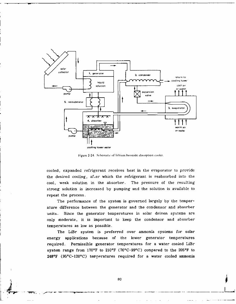
t return to
Ioin d cooling tower
i r -sation cooerir
PUMPo wav t
3. evaporator
cooled, expanded refrigerant receives heat in the evaporator to provide
the desired cooling, afer which the refrigerant is reabsorbed into the
cool, weak solution in the absorber. The pressure of the resulting
strong solution is increased by pumping and the solution is available to
repeat the process.
The performance of the system is governed largely by the temper-
ature difference between the generator and the condensor and absorber
units. Since the generator temperatures in solar driven systems are
only moderate, it is important to keep the condensor and absorber
temperatures as low as possible.
The LiBr system is preferred over ammonia systems for solar
energy applications because of the lower generator temperatures
required. Permissible generator temperatures for a water cooled LiBr
system range from 1701F to 210IF (761C-99 0 C) compared to the 205OF to
248-F (95 0 C-1200 C) temperatures required for a water cooled ammonia
80
• [ , -____ ____
absorption system. Most, if not all, of the commercially available
absorption units use lithium bromide and water as the absorbent-refrigerant fluid pair. Because the lithium bromide will crystallize at
the higher absorber temperatures associated with air cooling, these
units must be water cooled. A prototype ammonia-water unit, amenableto direct air cooling, has been built by Lawrence Berkeley Laboratories.
A number of equipment requirements and limitations must be con-sidered in the analysis and design of solar powered absorption systems.
The first consideration involves the type of collector used. The tem-peratures required by absorption coolers are obtainable with flat plate
collectors but at low collection efficiencies. Collection efficiency isimproved with an increased number of glazings and with a selective
surface, therefore, it may be cost effective to improve the collectorrather than to simply oversize. If concentrating collectors are used
(see Section 2.1.10.2), the associated higher costs and potentiallyincreased maintenance for the tracking mechanism must be considered.In general, concentrating collectors operate at higher efficiency at these
higher temperatures. However, the higher temperatures are usually notrequired to operate the space heating system. Therefore, the relativeimportance of the two thermal loads must be considered when selecting a
system.
The second consideration involves the means of delivery of the
heated fluid to the absorption cooler. Since, in many climates, the
cooling load is simultaneous with and often proportional to the solarinsolation, it may be desirable to allow the heated collector fluid to
bypass the storage unit. Other climates may require a hot storage unit
but one of considerably smaller size than the one used for heating
purposes. The important requirement is that high temperatures be
available during periods of heavy cooling load.
A third consideration deals with the problem of reduced efficiency
of the absorption cooler under start up and transient conditions.
Typical absorption coolers do not reach operating efficiency until after
an hour or more of operation time. A machine which is cycled on and
off regularly wil have a drastically reduced average coefficient ofperformance when compared to a machine in steady state performance.
81
This problem has been overcome in at least one installation by the use
of a cold storage unit (Beckman, 1977). The cold storage unit permits
continuous operation of the absorption cooler and thus allows some
reduction in the system and cooler size.
A fourth consideration is the need for some means of cooling the
absorber and the condenser. A cooling tower or some other low tem-
perature cooling system must be used to obtain reasonable performance.
All of the commercially available units require a cooling tower which is
another maintenance item. Current research is underway to develop
units that do not have a separate cooling tower.
2.7.2 Rankine Cycle Heat Engine Cooling. Rankine cooling sys-
tems are still in development with only a few in operation (Anderson
1979; Barber 1975).In these systems the shaft power produced by a heat engine
drives the compressor in a conventional vapor compression- type cooling
machine. The thermal energy input to the heat engine can be from a
solar collector or from a solar collector and a fossil fuel combustor.
The fossil fuel can supplement solar energy, or it can be used alone as
the auxiliary energy supply when no solar energy is available. Alter-
natively, electricity can be used as the auxiliary energy supply by
coupling an electric motor directly to the compressor shaft. Another
option is a motor- gene ra tor uts'ng a heat engine for generating electri-
city when solar energy is available and there is little or no cooling
load.
From state-of-the-art considerations, two types of fluid heat
engines are primaril.3 feasible in solar cooling units. In one type of
engine, the working fluid cyclically changes phase from liquid to gas
and back to liquid. The most widely used engine of this type operates
on the Rankine cycle.
In the other type, the working fluid remains in the gaseous state.
These engines operate on various cycles, including the Stirling and
Brayton cycles. For relatively low thermal energy input temperatures
(less than 400*F), Rankine cycle engines are superior in performance to
gas cycle engines. At higher temperatures, gas cycle engines equal or
better the performance of Rankine cycle engines.
824
Relatively low temperatures are attainable with state-of-the-art
thermal solar collectors, so the heat engine-vapor compression develop-
ment projects involve Rankine cycle engines.
In a Rankine cycle engine, fluid in the liquid state is pumped into
a boiler where it is evaporated and possibly superheated by thermal
energy. The vapor generated in the boiler is then expanded through a
device such as a turbine, a piston-cylinder (reciprocating) expander,
or a rotary vane expander. The expansion process lowers the tempera-
ture and pressure of the vapor, and effects a conversion of thermal
energy into shaft work. The fluid leaves the expander either in the
vapor phase or as a liquid-vapor mixture and flows into a condenser,
where it returns to the liquid phase by giving the energy of condensa-
tion to cooling water or ambient air. This liquid is then pumped into
the boiler, and the cycle is repeated.
In some systems under development, the same working fluid isused in both the Rankine engine and the vapor compression chiller,
which permits the use of a common condenser and the elimination of
special seals to maintain fluid separation in the expander-compressor
unit (Scholten and Curran, 1979).
These systems have areas that need development in matching the
solar heat engine with the mechanical compressor units of Lne coolffig
equipment. Since most compressors are designed for certain speed and
torque inputs, the varying operation of a solar heat engine will prob-
ably reduce the overall COP of the unit. Also the solar heat engine is
at high efficiency at high storage tank temperatures whereas the solar
collectors are at low efficiency which will also affect the COP of the
system. These systems are designed for large cooling load applications.
2.7.3 Desiccant Cooling (Scholten and Curran, 1979). The Ran-
kine engine-vapor compression and the absorption cooling units operateon the basis of closed cycles - fixed amounts of working fluid are
circulated within sealed equipment; the working fluids do not come in
contact with the building air. Desiccant cooling systems, on the other
hand, may be designed for open-cycle operation, since the only circu-
lating fluids involved are air and water. The basic concept is to dehu-
midify air with a desiccant, evaporatively cool the dehumidified air, and
* regenerate the desiccant with solar-derived thermal energy.
83
Two basic open-cycle arrangen.ents are feasible: the ventilation
mode and the recirculation mode. In the ventilation mode, fresh air is
continually introduced into the conditioned space. In the recirculation
mode, exhaust air from the conditioned space is reconditioned and
returned to the space. Figure 2-25 illustrates a ventilation system in
which a solid desiccant material mounted on a slowly rotating wheel
provides the basis for obtaining a cooling effect. The hot desiccant
material absorbs moisture from incoming ventilation air and increases the
dry-bulb temperature. This dry air stream is cooled in two steps.
First, it is sensibly cooled by heat exchange with the building exhaust
air. Then it is evaporatively cooled and partially rehumidified by
contact with a water spray. The exhaust air from the building is
evaporatively cooled to improve the performance of the heat exchanger.
After being heated by heat exchange with the incoming air, the exhaust
air is further heated by energy from the solar system and/or from an
auxiliary energy source. The hot exhaust air passes through the
desiccant material and desorbs moisture from it, thereby regenerating it
for continuation of the process.
Desiccant systems have faced problems of high parasitic power and
large space requirements relative to capacity. Because of their bulki-
ness, the systems may have primary application in the low capacity
range (i.e., residential systems) if and when ways can be found to
reduce parasitic power requirements to acceptable levels.
The Institute of Gas Technology (IGT) has been investigating
design modifications in a prototype 3-ton system. AiResearch is devel-
oping a 1-1/2-ton desiccant cooling system around a radial flow design.
Illinois Institute of Technology is developing a dehumidifier of a cross-
flow design that will provide more compact and efficient operation than
previous designs. Zeopower is developing a unique closed cycle
desiccant system in which the desiccant is integral with the collector.
2.7.4 Other Cooling Methods. Other methods, using solar heating
equipment but not direct solar energy, should also be considered.
These methods chill the thermal storage unit of the system during the
night and use the chilled medium to provide the daily cooling load.
84
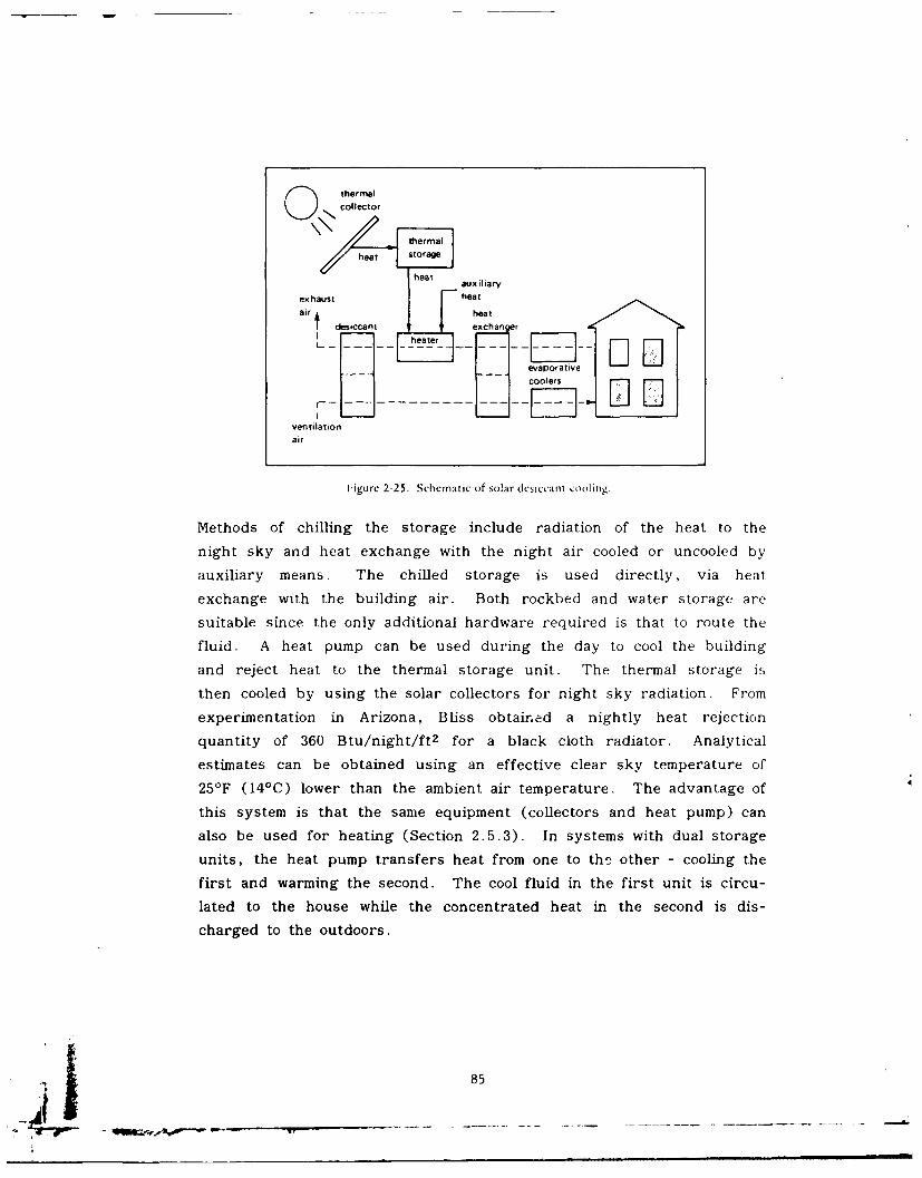
O thermalcollector
thermal
heat storage
heati aui ia ry
ex haust heatair t heat
usdesiccant Zexchanger
HheaterD
iventilationiK] oo s
l-igurc 2-25. Schematic of solar desiccant cooling.
Methods of chilling the storage include radiation of the heat to the
night sky and heat exchange with the night air cooled or uncooled by
auxiliary means. The chilled storage is used directly, via heat
exchange with the building air. Both rockbed and water storage are
suitable since the only additional hardware required is that to route the
fluid. A heat pump can be used during the day to cool the building
and reject heat to the thermal storage unit. The thermal storage is
then cooled by using the solar collectors for night sky radiation. F rom
experimentation in Arizona, Bliss obtained a nightly heat rejection
quantity of 360 Btu/night/ft 2 for a black cloth radiator. Analytical
estimates can be obtained using an effective clear sky temperature of
251F (14'C) lower than the ambient air temperature. The advantage of
this system is that the same equipment (collectors and heat pump) can
also be used for heating (Section 2.5.3). In systems with dual storage
units, the heat pump transfers heat from one to th2 other - cooling the
first and warming the second. The cool fluid in the first unit is circu-
lated to the house while the concentrated heat in the second is dis-
charged to the outdoors.
] 85
An evaporative cooler can be used coupled with a rockbed storage
unit. Night air is evaporatively cooled and circulated through the
rockbed to cool down the pebbles in the storage unit. During the day,
warm air from the building can be cooled by passing it through the cool
pebble hed.
The storage volume can also be cooled using a small refrigeration
compressor. Most through-the-wall air conditioners use such compres-
sors to cool the indoor air. This unit acts as the backup or auxiliary
cooling system - analogous to the backup heating system. If operated
only at night, its capacity can be as small as half that of an indepen-
dently functioning unit and still meet peak cooling demands. Nighttime
operation will be particularly wise if electric companies charge more for
electricity during times of peak loads on hot summer afternoons. Aneven smaller compressor can be used if it operates continuously night
and day - cooling the storage when not needed by the house
(Anderson, 1976).
2.7.5 Estimating System Size. The sizing of cooling systemcomponents is dependent on hardware, climate, and economic con-
straints. The cooling unit must be sized so as to provide the maximum
cooling load under conceivable adverse conditions of high humidity and
low or erratic solar insolation.
The collection area required is dependent on the fraction of thecooling load to be provided by solar. Very large collector areas may be
required for 100% solar cooling under adverse conditions of high humid-
ity and low insolation. Although a detailed calculation method, asprovided in the worksheets in the following sections for heating sys-
tems, is not available for solar cooling, an estimate of the requiredcollector area can be made by the equation:
A = Cooling load/COP
T qcollect 9delivery
p 86
where Cooling load =the portion of the total cooling load pro-vided by solar - calculate using AS}{RAEtechniques or others
COP =Coefficient of Performance of the coolingunit. COP is the ratio of heat energyremoved to energy supplied from externalsources. Manufacturing data is recom-mended for determining COP (3413 Btu1 kWh).
I T =average instantaneous solar insolation oncollector surface (i.e., at tilt angle)
0collct =average collector efficiency under design~collectconditions
ndelivery delivery efficiency which takes into accounty heat exchanger efficiency and thermal losses
In general, the collector area required to provide the majority of
the cooling load is larger than the collector area of typically sizedheating only systems. Collector areas for heat engine systems are
larger than the areas for absorption cooling systems due to the thermal
efficiency of the heat engine, which should be included in the preced-
ing equation (Swindler, 1979).
2.8 System Controls
System controls are used to turn on a circulating pump or blower
to the collector only when the sun is providing heat. Differential
thermostats are commercially available (typically $50 to $150) to turn on
the collector pump only when the collector plate temperature is a preset
number (usually 20*F) hotter than the storage tank bottom temperature.
A typical control strategy is shown in Figure 2-26 (Rho-Sigma,
undated) and the hookup in Figure 2-27.
Differential thermostats are available with high temperature protec-
tion and low temperature (freeze) protection. Another type of control
called proportional control is available. It is similar to the ON/OFFdifferential controller in operation. The difference is that the propor-
tional controller changes the threshold ON and OFF points and controls
87
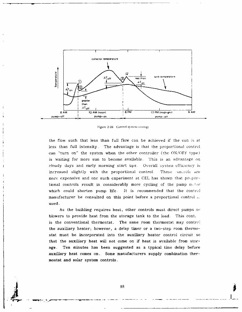
I
collector temperature
/ * Tof 3 less than tank temperature
grheate r
I Toff ]J
6AM i 12 AM (noon) 16 PM 12 PM (midnight) 6 AM
pump-off pump-on pump-off
Figurc 2-26. Control system strateg.
the flow such that less than full flow can be achieved if the sun i, at
less than full intensity. The advantage is that the proportional control
can "turn on" the system when the other controller (the ON/OFF type)
is waiting for more sun to become available. This is an advantage on
cloudy days and early morning start ups. Overall system efficiency ib
increased slightly with the proportional control. These j.on,.ols are
more expensive and one such experiment at CEL has shown that pr, por-
tional controls result in considerably more cycling of the pump m,,,)r
which could shorten pump life. It is recommended that the control
manufacturer be consulted on this point before a proportional control ,
used.
As the building requires heat, other controls must direct pumps or
blowers to provide heat from the storage tank to the load. This cont.
is the conventional thermostat. The same room thermostat may contrc'.
the auxiliary heater; however, a delay timer or a two-step room thermo-
stat must be incorporated into the auxiliary heater control circuit so
that the auxiliary heat will not come on if heat is available from stor-
age. Ten minutes has been suggested as a typical time delay before
auxiliary heat comes on. Some manufacturers supply combination ther-
mostat and solar system controls.
88
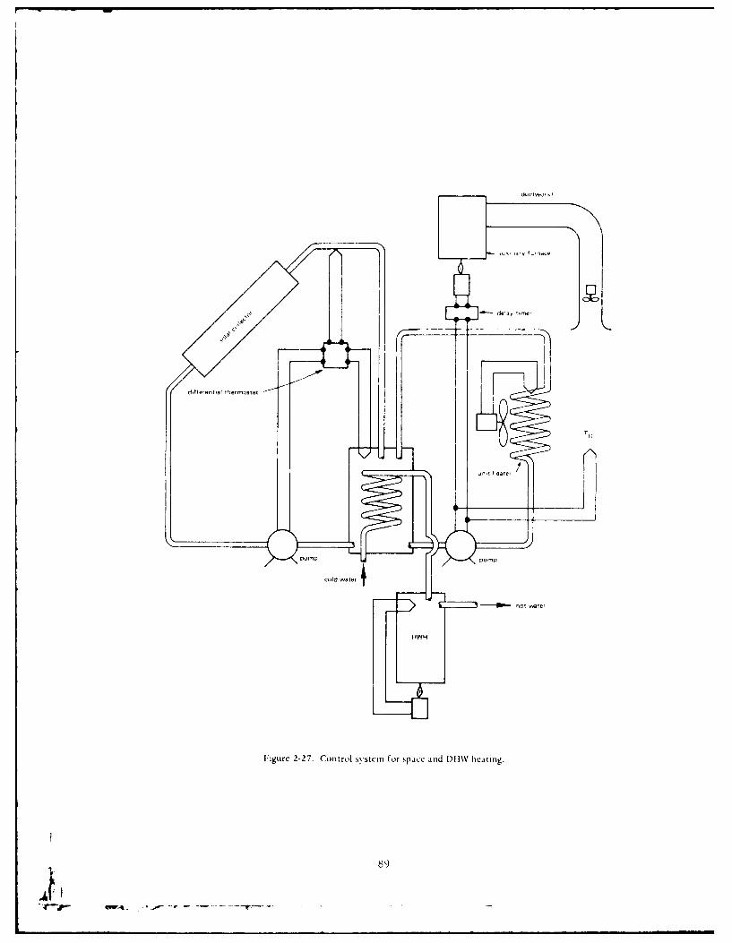
d.'a,
the-.sxat
unl eate,
P-P pu, P
cold ater
fb - hoT te,
HWH
I 5-
FigUre 2-27. Control system for space and DI 1W IICALllig.
89
"W4
AO-085815CIVIL ENGINEERING LAB (NAVY) PORT HUENEME CA F/6 13/1SOLAR HEATING OF BUILDINGS AND OMESTIC HOT WATER. REVISION. (U)MAY 80 E R DUALAK
UNCLASSIFIEO CEL-TR-877 NL
'iiIIII""

.
1 1 3-0 111112-2
111 1.0 12 m.0
11111 L2
Lq~_
MICROCOPY RESOLUTION TEST CHART
NATIONAL HURLAU Of SIANDARDS 1961 A
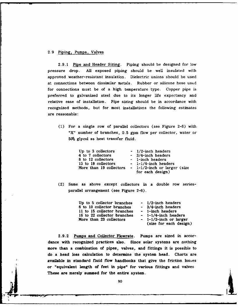
2.9 Piping, Pumps, Valves
2.9.1 Pipe and Header Sizing. Piping should be designed for low
pressure drop. All exposed piping should be well insulated with
approved weather-resistant insulation. Dielectric unions should be used
at connections between dissimilar metals. Rubber or silicone hose used
for connections must be of a high temperature type. Copper pipe is
preferred to galvanized steel due to its longer life expectancy and
relative ease of installation. Pipe sizing should be in accordance with
recognized methods, but for most installations the following estimates
are reasonable:
(1) For a single row of parallel collectors (see Figure 2-6) with
"X" number of branches, 0.5 gpm flow per collector, water or
50% glycol as heat transfer fluid.
Up to 3 collectors - 1/2-inch headers4 to 7 collectors - 3/4-inch headers8 to 12 collectors - 1-inch headers13 to 18 collectors - 1-1/4-inch headersMore than 19 collectors - 1-1/2-inch or larger (size
for each design)
(2) Same as above except collectors in a double row series-
parallel arrangement (see Figure 2-6).
Up to 5 collector branches - 1/2-inch headers6 to 10 collector branches - 3/4-inch headers11 to 15 collector branches - 1-inch headers16 to 22 collector branches - 1-1/4-inch headersMore than 23 collectors - 1-1/2-inch or larger
(size for each design)
2.9.2 Pumps and Collector Flowrate. Pumps are sized in accor-
dance with recognized practices also. Since solar systems are nothing
more than a combination of pipes, valves, and fittings it is possible to
do a head loss calculation to determine the system head. Charts are
available in standard fluid flow handbooks that give the friction losses
or "equivalent length of feet in pipe" for various fittings and valves
These are merely summed for the entire system.
901

The flowrate through the collector loop is determined by the maxi-
mum amount of energy which must be removed from the collector. This
maximum is about 225 Btu/ft2 /hr. Often a manufacturer will specify the
flowrate through his collector and this value should be used. If not,
an estimate can be made by determining the flowrate necessary to
remove the maximum amount of energy while minimizing the collector
inlet temperature (to maintain high collector efficiency). The rule of
thumb for this calculation is 0.015 to 0.020 gpm for each square foot of
collector area for water. For other fluids this can be scaled by the
value of the specific heat of the fluid as compared to water (C =
1 Btu/ lbm-OF).
Now that head loss and flowrate are determined, a pump can be
selected by using the manufacturers' standard tables and graphs. For
typical domestic hot water systems and space heating systems for a
house for a family of four, the pumps are quite small, averaging 1/12
to 1/20 hp and costing about $125 each. In some closed loop systems,
like a drain down system, pump sizes can be much larger due to the
higher vertical "head" requirements.If the water in the system is open to the atmosphere or if the
water is to be used for drinking the pump should be made of bronze or
stainless steel on all water-wetted surfaces to minimize corrosion.
Pumps will have longer life if they are placed in low temperature parts
of the water circuits. Pumps can be "staged" to give more flow or
head. Two pumps in series will give the same flow against twice the
head. Two pumps in parallel will give twice the flow at the same head.
Two or more small circulator-type pumps are often cheaper than a
single larger pump.
2.9.3 Valves. Valves, other than seasonal or emergency shut-off
valves, should be electrically operated and located out of the weather
or well protected. A vent must be provided at the high point in liquid
systems to eliminate entrapped air and it should also serve as a vacuumbreaker to allow draining of the system. To avoid multiple venting,
systems should be piped to avoid having more than one high poini..
Check valves can be added to prevent thermally induced gravity circu-
lation. A flow-check valve (used in the hydronic heating industry) will
91
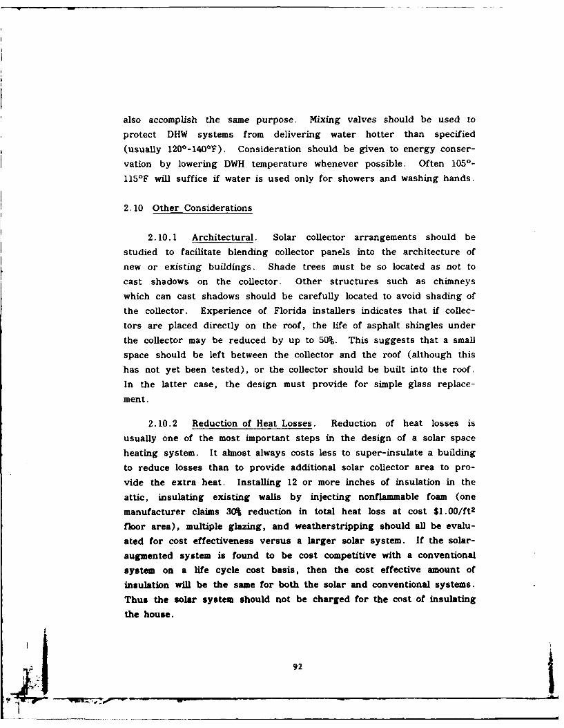
also accomplish the same purpose. Mixing valves should be used to
protect DHW systems from delivering water hotter than specified
(usually 120*-140*F). Consideration should be given to energy conser-
vation by lowering DWH temperature whenever possible. Often 1050-
1151F will suffice if water is used only for showers and washing hands.
2.10 Other Considerations
2.10.1 Architectural. Solar collector arrangements should be
studied to facilitate blending collector panels into the architecture of
new or existing buildings. Shade trees must be so located as not to
cast shadows on the collector. Other structures such as chimneys
which can cast shadows should be carefully located to avoid shading of
the collector. Experience of Florida installers indicates that if collec-
tors are placed directly on the roof, the life of asphalt shingles under
the collector may be reduced by up to 50%. This suggests that a small
space should be left between the collector and the roof (although this
has not yet been tested), or the collector should be built into the roof.
In the latter case, the design must provide for simple glass replace-
ment.
2.10.2 Reduction of Heat Losses. Reduction of heat losses is
usually one of the most important steps in the design of a solar space
heating system. It almost always costs less to super-insulate a building
to reduce losses than to provide additional solar collector area to pro-
vide the extra heat. Installing 12 or more inches of insulation in the
attic, insulating existing walls by injecting nonflammable foam (one
manufacturer claims 30% reduction in total heat loss at cost $1.00/ft2
floor area), multiple glazing, and weatherstripping should all be evalu-
ated for cost effectiveness versus a larger solar system. If the solar-
augmented system is found to be cost competitive with a conventional
system on a life cycle cost basis, then the cost effective amount of
insulation will be the same for both the solar and conventional systems.
Thus the solar system should not be charged for the cost of insulating
the house.
92
2. 10.3 Maintenance and Accessibility. Maintenance of glass will
be minimized if vandalism can be reduced. Collectors of flat-roofedbuildings may be shielded from the ground by a skirt around the roof
perimeter. Locating the collector in the backyard area of residences
rather than on a street-facing roof reduces probability of vandalism.
Double strength glass for top surface is recommended in hail areas, andalso provides protection from small stones. Still more protection isoffered by a screen of 0.5-inch mesh stretched several inches above thecollectors, but with some loss in collector efficiency (15%). Collectors
and mounts must withstand expected wind and snow loads. Collectordesign should allow for rapid replacement of glass covers. Pumps,
pipes, and controls should be reasonably accessible to allow repair orreplacement. Water pumps should be located so that leakage does notcause serious damage.
3.0 DESIGN METHODS
There are three steps in the design of a solar system: determina-tion of solar energy available per unit area of collector, determinationof heating load, and sizing the collector for cost effectiveness. Aseries of worksheets (Section 3.13) has been prepared to facilitate the
design process for liquid systems; see Section 3. 12 for air systems.The worksheets should be duplicated as needed. The design method
presented here is based substantially on the systems analysis done atthe University of Wisconsin, Madison (Beckman, Klein, and Duffie,
1977; Klein, Beckman, and Duffie, 1976). The complex interactionbetween the components of a solar heating system has been reduced bymeans of computer simulation to a single parametric chart of F IA cversus F LA C with f as parameter (Figure 3-1), where F I is a functionof energy absorbed by the solar collector divided by building heating
load, A c is collector area, F L is a function of solar collector heat losses
divided by building heating load, and f is the fraction of building
heating load supplied by solar heating. The requirement for advanceknowledge of system temperatures has been eliminated by use of theseheat balance ratios.
93
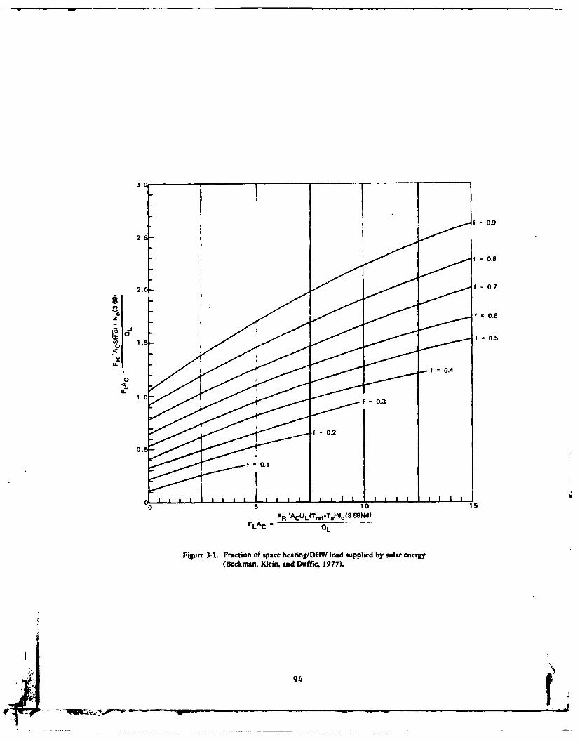
3.
f~ 0.9
2.5
FLAC = 0
.8
Figur 3-1 Frcto o0sae.a7n/ od upidb slreeg
6Dcmn liadDfi,17)
f94.
The method has been checked with computer simulations for the
climates of Madison, Wisconsin; Blue Hill, Massachusetts; Charleston,
South Carolina; Albuquerque, New Mexico; and Boulder, Colorado. The
standard errors of the differences between the computer simulated ard
the values estimated by this method of ? for the five locations were no
greater than 0.014 (1.4% error); ? is the yearly average of the monthly
f. Eight years of data were used for the Madison, Wisconsin, case.
This method, then appears to be sufficiently accurate for most applica-
tions and is a method widely used in the industry. It is the basis for
an interactive computer program FCHART (Durlak, 1979b), hand calcu-
lator programs (Durlak, 1979b), and HUD reports (U.S. Dept HUD,1977).
3. 1 Job Summary - Worksheet A
Worksheet A is a summary sheet that shows the effect of collector
size on savings-investment ratio (SIR). This is the final desired
answer to the question of the design process: What size collector (and
total system) gives greatest payback? If all SIRs are less than 1.0,then a solar system is not economical for the application at the condi-
tions used in the design. A period of 25 years' fuel saving is used in
calculations per NAVFAC P-442 as lifetime for utilities. Two methods
are shown in Section 3.7. Solar systems can be designed to last this
long. Computations completed on subsequent worksheets will be trans-
ferred to Worksheet A. Note that only the portion of conventional
heating systems cost in excess of that normally required should be
included in solar systems cost analysis. However, for budgetary pur-
poses in new construction, then, the total solar system cost is the sum
of the excess cost plus the previously excluded conventional system
cost.
3.2 Solar Collector Parameters - Worksheet B
The purpose of Worksheet B is to gather the variables needed to
calculate F I and F L (see paragraph 3.0). The first two parameters,
F R(0a)n and F R UL represent the y intercept and slope, respectively, of
95 Va
the q versus AT/I curve, Figure 2-7, applicable to the chosen collector.
FR is collector heat removal factor, r is transmissivity of cover glazes,
a is absorptivity of collector plate, UL is overall collector heat loss
coefficient. The y intercept (FR(-a)n) and the slope (FRUL) can be
read directly from Table 2-6 for a wide variety of collectors. The
negative sign of the slope is ignored and the absolute value used. The
y intercept is called efficiency intercept in Table 2-6. If a particular
collector is not listed in Table 2-6, choose one with similar physical
construction and use its value of slope and intercept. If necessary,
slope and intercept can be calculated for a collector as shown in Duffie
and Beckman (1974), but this is not recommended. If a manufacturer's
brochure is used for obtaining test data, the slope will be a constant if
the q versus AT/I curve is a straight line; however, if it is not a
straight line, the slope to be used is the tangent to the curve in the
expected range of AT/I. The units of FRUL must be Langleys/°F-day
for use on subsequent worksheets.
The term (mCp)c /A c is the unit heat capacity flowrate of working
fluid through the collector, where m is flow of working fluid through
the collector in lbm/hr, and C is specific heat of fluid in Btu/Ibm F.PThe larger the flowrate, the lower will be the AT through collector and
thus the higher will be the collector efficiency. A practical limit is
reached at (mCp)c/A c = 10 Btu/hr-ft2 0 F, so the design procedure is
based on values of this order of magnitude. The latter figure may be
taken as constant in calculating subsequent parameters.
The value for ec' effectiveness of the collector - tank heat ex-
changer, is based on manufacturer's data for the conditions of flo,.
through the heat exchanger. If no heat exchanger is employed betweci
the collector and the tank, then this term equals 1.0. For most hea*
exchangers, the effectiveness will vary from about 0.5 to 0.8. This is
a relatively complex term to calculate and a procedure is given in U .S.
Dept HUD (1977), pages A-34 to A-39. The simpler procedure is to
ask a manufacturer for design information. Most manufacturers will
provide this factor or calculate it. Be prepared to supply the following
information:
96
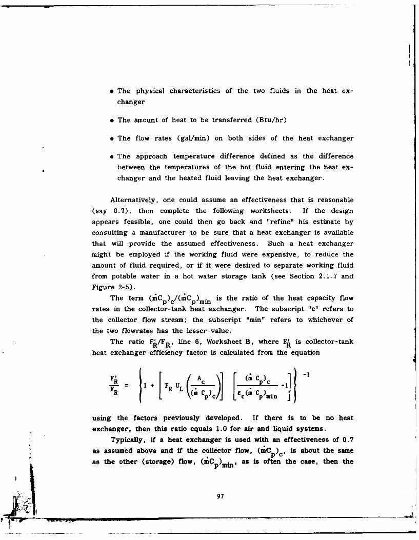
" The physical characteristics of the two fluids in the heat ex-
changer
" The amount of heat to be transferred (Btu/hr)
" The flow rates (gal/min) on both sides of the heat exchanger
" The approach temperature difference defined as the difference
between the temperatures of the hot fluid entering the heat ex-
changer and the heated fluid leaving the heat exchanger.
Alternatively, one could assume an effectiveness that is reasonable
(say 0.7), then complete the following worksheets. If the design
appears feasible, one could then go back and "refine" his estimate by
consulting a manufacturer to be sure that a heat exchanger is available
that will provide the assumed effectiveness. Such a heat exchanger
might be employed if the working fluid were expensive, to reduce the
amount of fluid required, or if it were desired to separate working fluid
from potable water in a hot water storage tank (see Section 2.1.7 and
Figure 2-5).
The term (nCp)c /(C p)min is the ratio of the heat capacity flow
rates in the collector-tank heat exchanger. The subscript "c" refers to
the collector flow stream; the subscript "min" refers to whichever of
the two flowrates has the lesser value.
The ratio F/FR, line 6, Worksheet B, where F1 is collector-tank
heat exchanger efficiency factor is calculated from the equation
F R + FPR UL j C -1
FR ( c) zc ( C )min]
using the factors previously developed. If there is to be no heat
exchanger, then this ratio equals 1.0 for air and liquid systems.
Typically, if a heat exchanger is used with an effectiveness of 0.7
as assumed above and if the collector flow, (mC ) is about the same
as the other (storage) flow, (mC )mi n , as is often the case, then the
97
ratio F/FR is about 0.95 to 0.97 for a liquid system. Ths is not true
for air systems which must be calculated. See U.S. Dept HUD (1977),
pages A-26 and A-27 for further calculations of this parameter.
The next factor is (i-)/(Ta) , line 7 Worksheet B, where the bar
refers to an average value of (Tc) and subscript "n" refers to the
value of (Tc) taken with the sun normal to the collector. This factor
represents the variations in transmittance and absorptance due to
changes in the sun angle during the day. Solar collectors are tested
near solar noon, and there is a reduction in transmission of insolation
at high angles of incidence which occur in early morning or late after-
noon. This reduction (called incident angle modifier) may be available
from the manufacturer of the collector since it is a parameter that is
measured as part of a normal ASHRAE 93-77 performance test. If it is
not available it may be taken as a constant as follows:
(ia) _ 0.91 for two cover plates(T- 0 - 0.93 for one cover plate
In the final two parameters on Worksheet B, corrections for heat
exchanger effectiveness (ec) and off-angle solar collection are made to
the basic measured parameters to result in F (wa) and FUL, which will
be used in Worksheet D-1.
3.3 Load Calculations - Worksheet C-1
Worksheet C-1 is an aid to calculating the space heating and
domestic hot water load for family housing. For other buildings use
conventional methods of calculating load; computer programs are avail-
able for this. For existing buildings, heating load may be inferred
from fuel bills, if available, see Example 1 (Section 4.1); or the Btu/ft 2
degree-day (dd) method of Worksheet C-1 may be used. Table 3-1
gives estimated Btu/ft2 dd heat loss rates for various structural types
used in family housing. If net heat loss rate is based on amount of
fuel used, load is gross load and must be multiplied by furnace effi-
ciency to get net heating load.
98
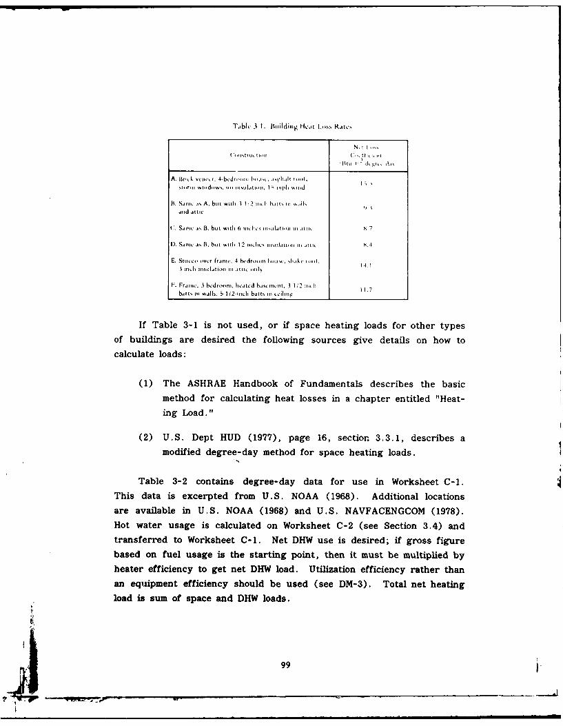
Tjblv 3 I. Building Heat Loss Ratc,
Coi, trI ,,,m
A. Brlit w. vcii tr. 4-bdr, i houst, .oqsph.ilt i x l,
sitrin witidiws. tt, iistil.tii ,. I , tiph tin. d
B. Si ic .is A. bit with II !2 i,, i Kaits tit %.ills
aniid itic
C. Samexx. is B. bit with 6 iilt - il1stl%.iJxIxn III Attll 7
I). Sixcli. , B, but wilth l 12 ix. lxs, 1lx1.l1.itlil xIIi .lAIRx X.4
E. Stutt co v.r (.ixixc. 4 hedrottn ix , sht" 4I -1. 14.
3 In. insulti-. i xiti, t afiti only
F. Franiv. 3 bvdri .... hti .tl tcd btsvxicit, 3 1 '2 ,It1 .batts xx wdls, S 1/2-ixch batts iII tihIxxg
If Table 3-1 is not used, or if space heating loads for other typesof buildings are desired the following sources give details on how to
calculate loads:
(1) The ASHRAE Handbook of Fundamentals describes the basic
method for calculating heat losses in a chapter entitled "Heat-
ing Load."
(2) U.S. Dept HUD (1977), page 16, section 3.3.1, describes a
modified degree-day method for space heating loads.
Table 3-2 contains degree-day data for use in Worksheet C-1.This data is excerpted from U .S. NOAA (1968). Additional locationsare available in U.S. NOAA (1968) and U.S. NAVFACENGCOM (1978).Hot water usage is calculated on Worksheet C-2 (see Section 3.4) andtransferred to Worksheet C-1. Net DHW use is desired; if gross figure
based on fuel usage is the starting point, then it must be multiplied byheater efficiency to get net DHW load. Utilization efficiency rather thanan equipment efficiency should be used (see DM-3). Total net heating
load is sum of space and DHW loads.
99
T,-Uti-
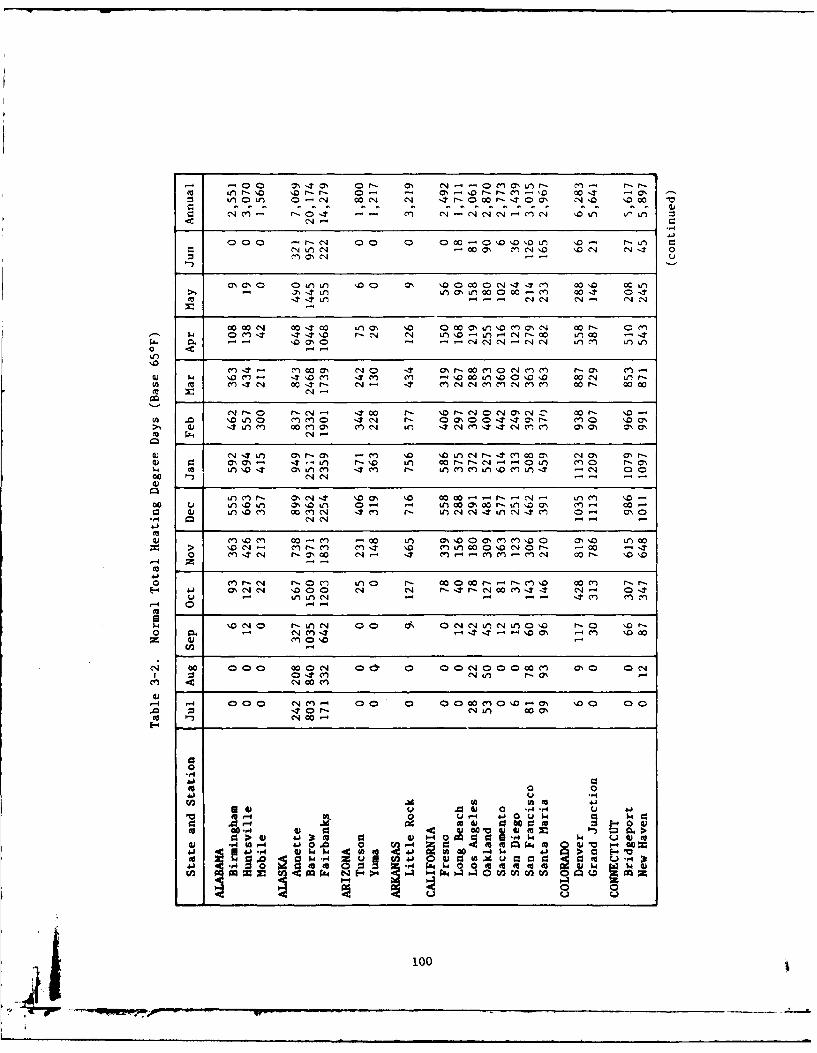
r, 7 -00 0-O 0', 0' -0 ', r M- rr-r- \Q~' 10 r-r- 0- ON r-0 - r- cw '0 ID 7 00'
a C) a - 0 -0-7 -- C'a 'o Lt)1 ' \0Lf ~Ln C
000 -r--cn 00 \0 000..''0Ot '0- -u
3N0" 0~Lr '00 0r) ' 00~--t 0 cc4'l 0 ccir 1Ln- - C'J4 C14
cccC ccrc Lr ' D 0 0 O cc- o
0000- '0'T00 V -ON- c~ 1f0c w NL 0I N 00r V0 . ON 0 -- n l e
'0
o m~7C 0c- r- C J -M m r - Ch c
to m CY -N 0 ItN -c r- q C M OMC M M 0 cr- '0c
VZ c-.IMM-C.7u r a 00r-0 -T '0 '0~--cca cn.a 0 %0 O
a c C L 0coL , r-'. Tc t Cl 00 C7 -CN 00 r4) C: o-- -\-) r 4 n c -r-C4 "0L) M 0 r1, (a _______________) _____m______________________\ ___M__M__IT__N
i cn~0j a\'Lt 0N -* ccCt'a \0- cc-000 uV n0 i Lc0C 0% \0 J - 1- Jn 00 N 00 -'4 0nl N n 0
>VoC -~'c cn - M c Ltr c n00acc~o a.0 \0 c 00 m Itc'N f- acc CN r -. - cn M M cq 00c P 0'
-44 N -- 4 0 C4 0I
- 0 -
U, , -
e'4 00 0oo00 ~0C4I os: drO N W 0 00' 00c ~ a C-.4I :1 0 --r m'u C14 o
-4 1-4 4000 C M -4 00 0 C 0 ccn 40 \.D % '00a 0.0 0 t0 1- " 4ct 00 0%to N- e'co-4
0
vc 0 -0
04 -4 4 0 *4 w C .)C. IVwacc 0I 0 (..- d.0. . 0
cc 00 4 v w PC w 0 w m >> 4J( 3t V 400au4~ C: toJW *.~l-4 41 4 0 cn-4 aU ccc ~ c m' W-=0
-W -4 Qw w .4 . c " . 0 -4 $ 4j > a e-to04. I~~MU~ gc z u H3
. .. Ac Wi 0I4 Mocc c M ~ M Mm, 0a NI 4 Z.
~ 0
100
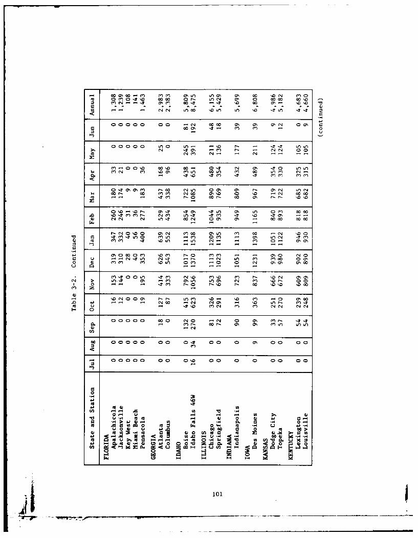
-1 00 ''C C(7% 00aLe M CV L) O 0 0'. (N '0 ~ 0m 0 cn04'.0 0 00 0r- tC14 ON. a 00 00 0
cy N~'-- ON.c M 00t 'T '0 00 a7N- 10 D
C:C
000 0 0 -4 00 00 ON ON ON N' 0' a, r_OC A' 3- Cl -n 0
0 000 0 V) 0 I4n '.0 r-.N IT1C ON - C') f-- C14-
cn 00' ID 00 00 04 IT a' 0 0 V)Ul
-T -1t0 It -.T M~ m n
0 IT C ' N e r- 0O C4 Jtf O Ca' a r- aC 0 Ln C4w- 0CO!- CO C'5Cl N'C 0 a'' 10 0 ' 0 - C14 00OCO0 I 'l r- a~ 0C Cr- 00 a' r- r- '.0'0
. o IT en .nr- C V e T' It' m 'T a' - -CC4) N 1 '0- C -j LnC L -4C 00 N. 0a m-- 0 0 0
r. IT Mj T ' nj C V V)~ MO' Ca a' m CC IT CmZ -f m IT-0L l 1 n C
m0 0 00~4~ a -It Ce) \0' -l a' 0fC m 4f Cu r C4I n " It "0u - cq5 V- co C 0 a'a'C
M IT- -a -- It n 1\0 mD CY r- \. -- MC
-4~- -O Cs4 00 M--r nc om0
.0 410 t C4 00 -4 N~' m o r- m ItaC'. u Lr. a' M-C C'st (n~a C) f q '04 0 C4
0000 00 - 04c' r- -' C ON m.0r-0 '0CY, r, 00- s O n L)L
4) C-
00 00'00a' 0 0-r '0- '0 ON cc a'C
e- 0
.,q,
414
54
(A -4 -4 M0 Vc .0-4 LI 4 14 -4 cc >1 4
10 m- t0 4 4) 0 4) 41) 1-40- W J4 -4 Mc to .,q 0. 4 0-4
W .0 U00 0~ m4 0 k 4 0 H Cm 4J -4u 0J u 415, (AC cc 0 0 0 0 >C
4) (a c-H W1 cc0 C30 z 4), -.4 0c4. 4) ic Y0 U-H c H C34 tv -
40 -C ~ 0 -44- *HO to1- ca Vr H0 ) 441 1- Q04M4) r44) 0 4j 0 0 0 0 Z .0004 0 00
Q 0
101
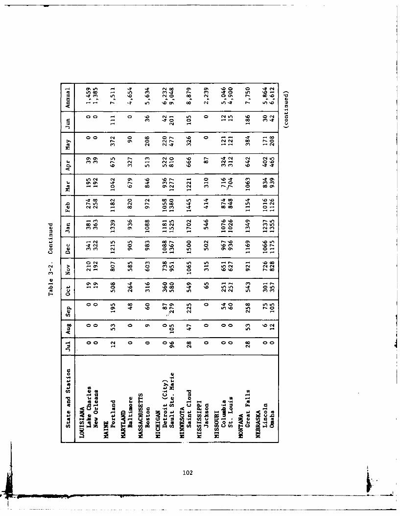
MI -n %T -t C14 00 % 0% ' 0 0 .Nm in~ co I C.) cn.t r-. M~ 40 Ln ' .:j Isc en '.0 '0 No4 0 00 % 0O r- cc 0 10
0 -c- C- 04 tA '.0% LA4 r:- LA'0S
400 -4 0 '.D0 * N- 'A 0 N tA '0 0N C
-Y -4 40 0 -- 00 MIt 0- N .- u
0 0 N1 0 00 Or- '.0 0 "- IT 00r-. ON 0 C4r- * N 04 co r-
0l N 4 cn ~ - (Y) -4
a%% as L r- (n ('JO '0D r- - N C1 1 nIw cn1' (n - N - N. '%0 Oo C- 4 0 %D
cc '. 0 ~ 00 0% C .0 (C14 (n.0 44Cr
-4-4J
-4 00 L14 L C14 00- 0 ul NI -0 0T '0IIDU -L 00 -4 i 0 , in 0 . 0 0 - IT0c '.0 '4
o ) 04 C*' Go as 0% CV) ir -A 00 - 00 1. .4 4 .r-
*l ON %0 U 0 (* -4 IA 0 A % -'! -D \JD ON 00N o \0 m o o00 0 (~A '0 - r-e c'j- c'jeLj
m cn 00 n A '0 ?--0 0- o4n '0 a % m -00
C: '4 N 4 0 0.0 - '00 a 0 LALn \. \O rA(0 0) cA Nn CC4 Ch& a, 0N LA Lna
04 N % 4- '0 00- W) Lfn '\0 L061>a ( 0 0 n0 % 4 Nn N1 Nl C14
1 00C- co~ 0n ID O r- 0 0 n N0 C7 r- c
4)4
.-4 00N 0 oo - 0 0'0 0h 0n 00 M 0m~0 Q n 4 M (nL W)NN n Me
0 04n 0 - N1 ) 0 IT0 c )V.4 :.4 04C1
.,j
F4 4
M041 4 '-'41 04 to ., g0v A-I c 0 wa 41 V2 U a cl ., 4 0 4 C
00~ 00 41c-4 4
41 4,I 0 .3-4 I $04 r C. CA2 Ad1 tv u
Z 0 l 0 )-4 00 do " 104 04 g a lU
102
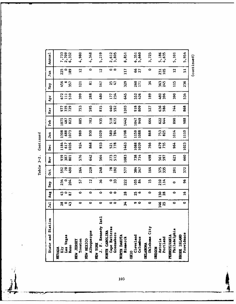
.-4 e~'n * 0 00 0% NU -n -'0 %,'0U .00 en -en c T ."0 U, #11 0 N4 00 M 0 U, .
v-r-cj M ' m~ M '4%D00 c00 e C r- -40 -. %
LO a % C1 0 N4 00 ND 0~ 0 -U N -0 N 00 M - 4NC0 - U, 0
0 .N0 .-4 OA 0 4 I )U nIT, -n-40
N UU, N 00 '0 r- 4 r N l '.0 CP% ONO. a -.
r.t-- % 00 00 r--C m 4 UN 0M 000 0o GomV) M.U v N -T 1C-4 %D0 U,. - M7' Mv UM
r~,0 Cv, m, U, Or n N cWn 000 44m r, %0 -4t 00r-. -cn N U, 0% - 4 LnU 0 -4 N co -Z %a
r, AnCI. f". U, 00 ' N m Go U, %.0U W) Go-4
Un v--~ U, L CY) U, CON 04 C-4 0% -T 4 N-T 0 00r- 00 N 00 0 CV) ,-i -.7 I --. '0 N -4 0% 00
4) 0-700 00 9"- m% U,'.Q . 00% '.0 %Q'.0 00 m
c00 en ON0 0 0% 40- Go C7% c M0 inU -4r 0V 0 0 00 r- c0 MV C4 0000 0 U, 00 %0 UN -1 -44) to en %Q0 as 0% 0 U,9n r- -0 00 r- cO 0 -
-T Go~ M4 14 Go en .co CA S a l
Q 00e N* C14 cv, C4 - '.0 00 C) '%0 r. C'% '.C N0 4) -'%0 0 m% 00 0p% UL" r- 0t 0 r- '. 4 % 0
1 4 -4-4 -4- -
(70% r, 14 '0 N -1 (nCV M 00.4 c0 .4"l v 0> en C00 0 r- -. 1'0 r," 00 mv- 0% m .0 No '. 4, 00 as cn 00 U, No U, NU L 0 Ir-I-- -7 UU '0 %0z
N 000 .4 0% 00 GoN I'4 4- -4 UU -S-'L N41 ON 0r-0 ON NO 04 r. 0% I"- 00 -4 %D v--cv 0% v--uC U n IT 4 N NN 0 '4 U, MvCv (n mcv N en~
.- 7 4' N %0 0 M N U,. U, t 07 IT Ncn(v 0 U, -4 cfn Mv N 00 -4-4- 0 m%
00 cn 0 r- 0 0 0 0 0 00 kn %Q 0 000 0 '003 -4 Go N N (vN
co ONCv 0 0 0 0 -7 %0 0 L", 0
0 N 937
010 406 . J0L A 3t m udo4 cc0 m140 v a0a- 0
sO c 44 to4J2 ! 4~4) W.4 1
co to hi g44 ~ 33 .* r. u00 A0 m 00w '
4c1 w0 I ;-a ~-4 0 .4UMI-4.4 0U l0 8 .1A. 0
103I

-4 (n 1) co 0 17cn a0% CA ON - 2 %~0 0%sCnI cco00mI c'n 4- I- 0 -* 00 11 iN I'D0 C1 N r- CA %D 'n r- r
M 0 n I D s '0 ~ r~- Lf L, N- I - 2 It 4 0 0 N 0 C140
o s'o 0 00000 -~ 0 0 I- 0'. 0'N IA e cco c7% ON -- - V
0 %'0 0 00%000 n m~ r, N1 \0 IA 0 C -.-N 44 It n n V IT as M% P'- 0 co
mN C '4 NnC4c nc
41 IA Ch OO IDAV)0% 0% -4 \.0 '. 0 -T0C14 N II L' IA 00c 0%0( m A -4 - 0'h 0 V) -S4 !-IA
-, C4 Nn 400%%I (ID NO %0 cc .%
I.' 0% ON C\ Ln-'-0 (no r c-n r- 00 e .- A -N N 0 in (n M 4 r- - e IA IA '0 - 0 C 0
c% IA1 IT .40 A 0 r-I * oV L O IA a'. 0l ONC' '.LMJCV \. IT0 - 4 N 0% cn \JD IA r- ( CN-. 0
r- en G Ln u-4Inc 0 N m~ 00 00 0 IT~'. m % 0 -V 0 0 en fr 0 0%oc00N 1r. - c'n m~c 00 %ONP-- N
41C4 C m 0, -4 N '004 -n IA ON r- cc 4cn CD N 0C3 u r t- m -T N- N -- 0 I S Ln % nc n 0a
N- - l N n N 0 4 O Nas 00 1- I C0N %.D IT
1 0 C-. co en 11 C14. 00 00 0 It '.0 Le) (M N 0 a 0
-) - 9- - -
N 00 ac 0% 0% '. N . 4 0% c7 0l as % T 'T- C No1 LN cc 4F \9)I4 cc cc 44 en en C0%00 fl I 0L
m' u-nc 1 -T- 4 nL
~0 -n cc 00 0N - 0% 0% '0 ON 4 44-4'IM 0 C4 A c A'.c., ~ ( %0 N- IA c ri 0I
4) 0U 4- -. 4 44 IA -. C14 44
cc. 0
:3 -n N* -4 NVNr
00 0 N 0 00000 0 0 IA 0 a 0 o 00F- .'c~:s -4 '4 4n 0A44 IT 3
4r
to -A 0 IANN
&1.) r .4.U a4 a 4
40 a u 4 * 0 4 4 4 a 04 1 -90 W O640r4 0 40 .g 44 4a a.. 0 t; 40 040 -4 @3F 4 W
41 > 4M4A H.~, e..4 r4. 0J 0-4 $4 Wd r4 31to P4OC -- > 0v 00 P4M~ W~51.44 $4U A~ 1.4r4 0 ~ 014- - .. OWN 131
0O ka U, MN CO E @*4 U U0:
104
3.4 Demand Calculations - DHW - Worksheet C-2
Worksheet C-2 summarizes DHW demand determined by conventional
methods: manual DM-3, chapter 1. Table 2-9 (Section 2.3) gives hot
water demands for various buildings. Table 3-3 gives temperature of
water mains for various lorations. Net DHW load, Qd x No , (Qd is
Btu/day hot water demand) is transferred to column (W), Worksheet
C-1, if a combined space heating DHW system is being designed. If hot
water demand is calculated from fuel bills, a gross figure is obtained,
which is entered in column (U), Worksheet C-1. Net demand = gross x
nw) where qw = heater utilization efficiency.
3.5 Monthly Solar Collection Parameters - Worksheet D-1
Figures for QL' total heat load per month, are transferred to
Worksheet D-1. Solar insolation, I, and slope factor, S, are obtained
from Table i-I and Figure 3-2, respectively, for the location and lati-
tude. If measured I for the location is available for several years,
then the average of this data should be used. The slope factor cor-
rects insolation data from the horizontal at which the insolation data
were taken, to the tilt angle of the collector. If the tilt angle is lati-
tude plus 10 degrees, then Figure 3-2 may be used for S. For devia-
tion from "latitude plus 10 degrees," see Duffie and Beckman (1974).
These calculations apply to south-facing collectors; no correction is
needed for collectors facing up to 10 degrees east or west of south.
The air temperature, Ta, is the average daily temperature taken from
local records or the Climatic Atlas of the United States (U.S. NOAA,
1968) which is excerpted in Table 3-4. The factor (Tref - Ta)
accounts for the effects of ambient air temperature changes on collector
heat losses. Then the parameters FI and FL may be calculated. Spe-
cial care should be taken that units are consistent, so that FI and FL
will have units of ft " 2 . The factors (3.69) and (4.0) are necessary to
achieve this. The factor (4.0) converts hours of sunlight per day (6)
to hours per day (24).
105 V
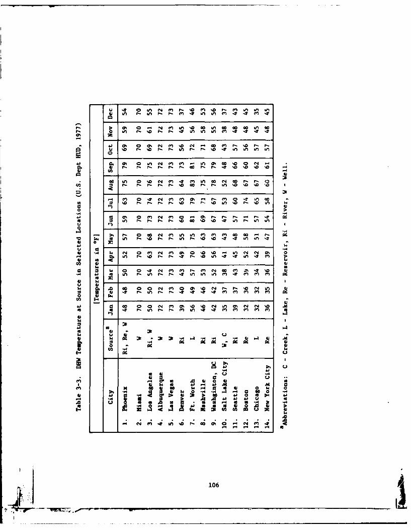
4; 4nr 0 U, r- mV f'0 CV0 m I V, m It
o %A %- a r- r- , 4n , mA It, 4 4 CV,
00 0' 0 % C1 (V, '0 cn - 00 C4 00 '0 r- Is=1 '0 Ps r- r- r- 40 4 'A- 'A '0 'D A N
04 M I N en, (, Os 'A M% 0'0 N Vn G
C3 V 0 '0 '0 >0
41V 04 N (n,(V 0% r" r- (V , 04 'A 00
U in' r- r rr- 'C 0 %a %D '0 'A '0 - '0 'AM~u
a 'A p- %Dr- r- in P. %0 4 %* r-'MA0
0 .,4 4 'A C0 r- r- 'Ar '%0 0 '04 'AU,1 C4 aV- 0 4 Ln r D % t n (
W 093 2. $4 N 0 -4C4 N 4 (V, 0% 0 n '0 ' V) 0% N 0 w
-r4 41 4 U, r-'0 fs r- It ' 'An 4M in enItm(n(V U
0
0 ~ 0 N mV mV %a %0, N 0 m~ N 4 '0 Ad* 4. 'A r- 'A r- r- 4 'AU m, mV 4 mV m, 0V
41 V
0 ~ ~ ~ ~ ~ ~ ~ l U0 V -'r -44 4CCCV V V
In I-a - 4 a i14 0N 00 0 0 N- CV, 0% '0 ' , 0 0 -4
A -'r -V 'A 44 UV, con AV CV, AV U0I,4
10

I~0
ULs-In
N'\~L4;n >~
o 020
C"
107
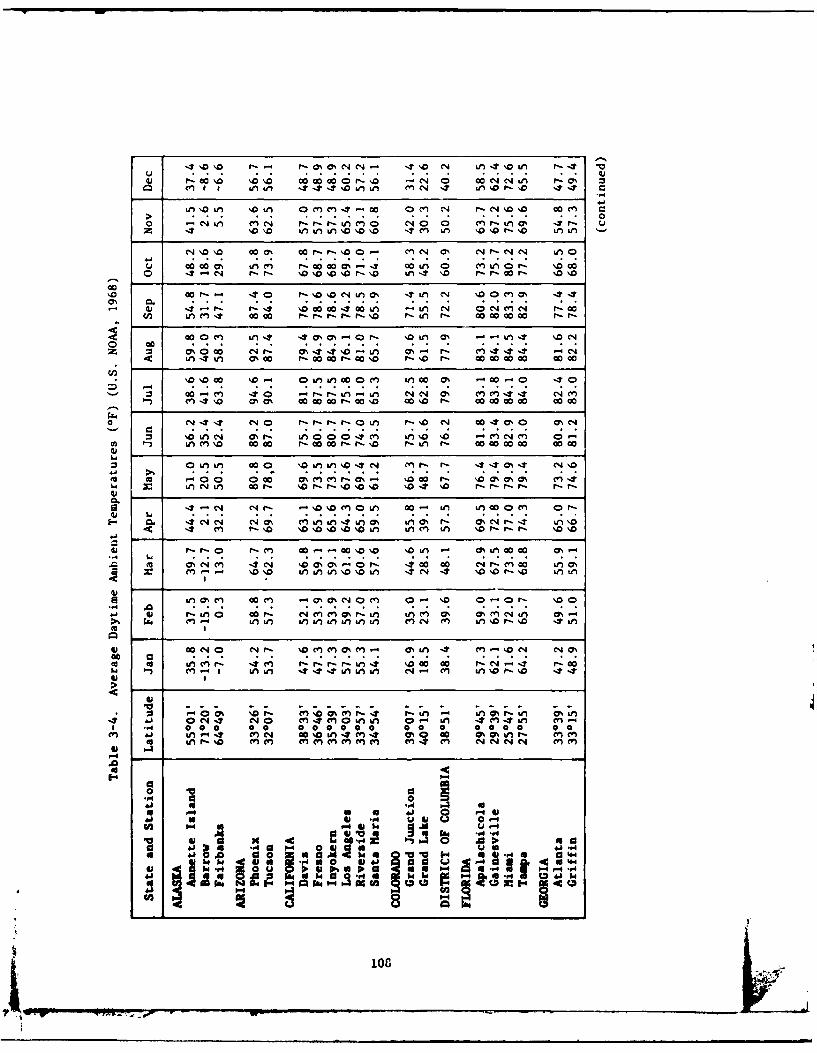
-4 J I 1000 '.0'.0 cy 0 0 % N001- It. 0o N .4f In W -a
11: 00000% 1 r0000. 06 0iAP 0 4c LA1- r.: 00
m L n0 oat- -30 %u 0 % 4um ('(nNan %O 0 4.It
\10~C~ \00 Le inoo\4 It-.--. e-n 1- \00000000 Le) -
oZ N9 0900 0'r- 09 0%- I': C14- -'c'J 1 c r C LQ 0Go0 LM4L m%0 r-oo C7% - 4. 00 f) 0 IV)0 r 0\0 0 000
Is C4'0 '.0.- 4 0 14) 0 Z \0 Ln 1 1 0% 0- 0 - \40
1 '4.0 00 0000 I-.T'. a0. I-- 000000V0C L N 0 0000 I 1
wo _ eJ4 1;J r1--I--I0* f -s 0(' L 4 000% 0%e.JrzCC
(A ' Ln M 110 000c r -001- , r '- Ln I- 000c000o00 0000-
0 000 0 %~(~-0.- '0 - '00 O. (~Ln IT tn 00 r-. 0 c r- co 0' '04 r- 00 co 00 00 1-1-0
en I---- P-C 00 .00 r-0'D 0\.D r- co Go 00 c c00
k44
:1 14 0%eJ) N (' a,0 0%0- 40Ln0 000- n Ln . 'r -4 M L0%w ne C 1..- '00 r, f'0 0 '.0 LA %D % 4- '.0'.0co ao o o AoLc
z L0%' LM L co \10 %0%C4\0C N m . 0-1 -.%IT C %.0
rL. LALA NAL tn) ('o r-F~-. %0r 0 4N
\010 D\ \0 I- 4(m P--Pf*ui Lei0 00 0 r-N r-O\4!
4 -4 0 Q*
(n %0% 'Or- in Lm 0Q% \Lei C It.f - %0 r- LA 0Le)A
4 4.) C0N4 NO 4( 0A9LA W; LA 4('1-.?C C LA C44 en LA.4 (LC' Ln 7 A inIn n I C4 m' In \%0%L- C" IT "r
1 LA c,; (c 141c r- c Aa a c :4 r4 a6JcI (
0 4,4.) I-I 4 -, ' 4V 4 a 0 .0 a r n, e
It. :0 uw :0dofe cl 6) .40 aj
Ad ~ u a -A4 C34
64 W -A .44j 1* koI~~ ij~ L6 -4- p
- 100
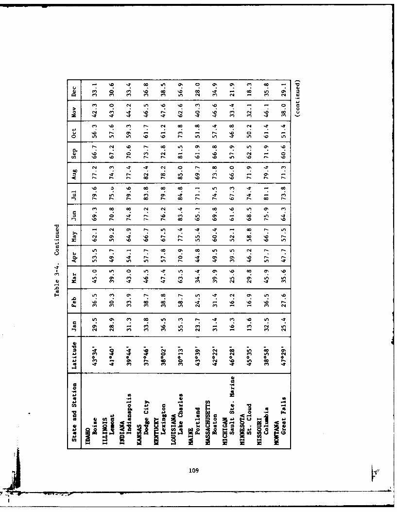
% '0 NT 00 , 0% 40 0% 0% (l) coQ . 404) ~ ' ~ '0 0 . 0 4 - 00 , 0
9z M4 en~ en CV m , N m~ N - m' N c
0 N CV) '0 - N 0e'0 n N '.0 00 uz IT 4T 4 4T 4T %0 'T en Cl 14 m~
C7 '.0 ( r- N 09 09 4 9 00 4
u %0 r, ON m - Ps '0 0Qo n U, U, %, 0 '0 Ps W)u 4 ' 0 U, Lf
rP: CN '09 r 09 U, 0 09 0% U, % '
4) '0 r- 0 cn N - - NO0 r- N -ul '0 '.0 r- r-- P 00 '0Q ' Ln \0 s '
-1 U- N 00 UM 0h CV) '0 . % -r- r-Ps P 00 Ps 00 '0 fl- '0 r- Ps
-4 1 1 09 0 9CN in U, 7% CV) 0% 41 ,- IT r- 4 Cl)r- P P, co 00 - co 00 r- \-0 P 00 P
C 09 09 N N 49 - 00 '0 0% C
0 0% 0 -4 r- '0 en~ U, m - 00 U,
4)- 0 r- Ue 4 -T IT - 00 r- U,
W) '0\ ' 0 '0 r- U, '0 U, U, '0 U,
40 0n U, 0 -U, 4 s U, 4 n 0% '0 0 -0 '
m~ U, US M '0 r- C.) 41 ON in as U, U,4) cn It It. It \. M '0) C14 C4. m
U, as. p- co Lei It U, 4 0% U, '
0) ' C) 0 0 00 4 - '0 '0 '0M M4 ~ CI') M'' M'' U, N- CV.) m N
U, 0 CI' 00 U, Ci' P- CV?) '0 U
as0 00 - MI" '0 U, Cen' -. '04 C' N UOn N N cn' mI' mI' U, N1 MI' .n -CI
mI' 4 4 4 - (n N MI' U,.- 0 0 0 0 0 0 0 0 0 0 0 0
.14 I) . so Ps 0 0 C) N ' U 0 P
0 414
06
F0 01 41 C- 4.
2~w U).4 .
109
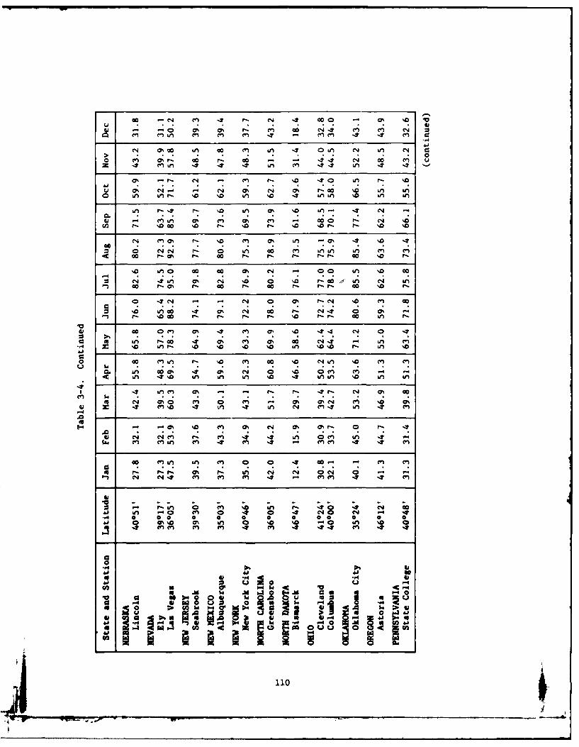
00 -4 cn -2 r-. N1 -2 co o 0F% %0 V
4) -n 00 r- co .1 cc4 ao on u~
u ' C7% ~ C1 C14 0% N 0% 4- ao ca L
N 0%M 0 in %0 Co Le As -2 OnLn Ln kn
w en 0%'. 0% M- cc -. - 0 4 N- C4 %0
w % -I0- %D r- 10 '- %0 % 0 a1l r- '
z 0 N N - N 0 0 CV) c %0 1*, IA eo o mr- '0 '0 rA r0 4- m 0A 0 ID r,
<4 -4 (Ln 0% C14 % 0% C' D r-o &n N '000 r- 0c 'l 0 I- a0 '. - '0 '0I- co %a f'
N0 O n cc- 0% N w - 0 C7% '0
a c ro r- cc '- c r- r- cc '0 in .
0Q kn P. 4 -D a 0D 0%) '.N 0 %a cn %
'0 mLn 4- .0 n 00 No- C4 0 %a M e
0 -%W cc l CLn in- '0en 0 Ni ~ '
0. as 0004 cis 0 ' 0c%' r- -
N C4 4 mA (n (A '0 4 LMA '0 m
Z4 -4j In c 0% -n i. N- 4 N % c
.,4 N 0 0 0 a a % 0N C 0 0
I.'- 00 '0 .1 onN0% 0'-
A 14)~~~~~~U N c41 m 4 m c ~ m
611
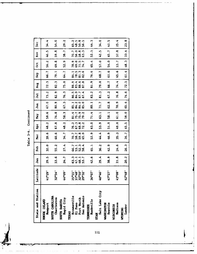
It 4 4 1 C14 Ln0' c4 4l fl) 0 Li CC)
cn C Mif N %04JU 4t cn 4n N N
> f CO 0 r- ro OC c &f F- O0 as0 0 0 CO N'0OC~ 00 M eq CI4 i
z 4 n aI) Ln F-U %0 Lfn 4 CO) CV
v %.0 aA N co0 -as %T 4n (n coo n %.0 Ln r- %OF- r- 'o in in in -
r- - Li iC '. '.0 19 '0 %9 0 4
4) '.6 F- 'T 0 O~ - 04 '.0 Go 0 V)0 '
&n % -- 0D 0%'C %0 r- 40 0010 % %
:3 N in %.0c COr -co P- No Nr - o I'- coOC O co Go co c r 0 P-- F-
0N 0! % C 0 I- Ni c? C O 119 .0
M N '.0 % '1 P, r- M .-4 P. 'o It' r - o Go- oOC 00 C0 0.0 c-- FD
0 0% C O-'.0 .9 9 - C9 %:3 F- 0 F- i n 0 W) 0 04
%D c0 00 c.0 OCC 00 F- %D0 r- '.0
%D c0 mO P. 4 0%N 4 e 4
004 CI 00 C14 Nn Mr -00- N. in m0 LM
o %T 0 0N M(OO 0n 0% in4 . CO1 F-D MO '.O- N LM' (z -) m% (n
E- 4 * M. 4 -o4or '.0 i0 (Y)4
w V-1 l 4 V C
a 2%M0 P.0 F-- m--O 0% m 00 cvI a-
in 0% 0n 4 4 &CO0M N '0 n0) 0 C0 '0 C0 0 ~ 0 an 4 4 0
.0
ph 4. . F4 .44j F.4 .0 'O V, C3 wn l. 4 '~~a4., $4 en r-.inn4 cVM 4
lf ' F- C - 41 '.0 4 0 CO
w0 - -A 4j- 4- U)
4.) 93 to 4o F-40 a. a Z. C0 N* ~ ~ ~ g w wV Go
4 cN (9

3.6 Fraction of Load Supplied by Solar Heat - Worksheet D-2
On Worksheet D-2, first select an area of solar collector for study,
based on experience, similar design, or arbitrary size (a collector area
approximately one-fourth to one-half the floor area to be heated is a
reasonable guess). Area is multiplied by F I and F L factors from Work-
sheet D-1 and the product is entered on Worksheet D-2. Then from
Figure 3-1 pick off the values of f for each set of values of A cF Iand
A cF .* Calculate average f= IQ Lf /YL* Then select other collector
areas, larger or smaller, and repeat above procedure so that a trend
may be observed in the following cost analysis calculations. Usually
very sunny areas (I > 500 L/day) will have highest cost effectiveness
at about f 0.75 and not so sunny areas (I -300) at f 0.50.
Ilse of the simplified slope factor method (Figure 3-2) results in a
small error in ?, the fraction of building heat load supplied by solar
(average over 1 year). A correction curve, Figure 3-3, will account
for this. The error arises because solar insolation is composed of both
beam and diffuse radiation. The simplified slope factor method treats
all radiation as if it were beam. The correction curve was derived by
comparing the T calculated from Klein, Beckman, and Duffie (1976) slope
factor method (taken as correct, but involving complex calculations)
with T calculated from the simplified method. The T calculated by the
simplified method will always be "too high," thus overestimating the
amount of heat which could be collected from a given collector area.
Thus the percent correction should be subtracted from the ? by the
formula:
f correct =fslope factor method (1-error)
An error of about 6% will occur for an T of 0. 7 if this is not corrected
by Figure 3-3. Henceforth all references to Tin this document will
mean the corrected version as given in Figure 3-3.
112
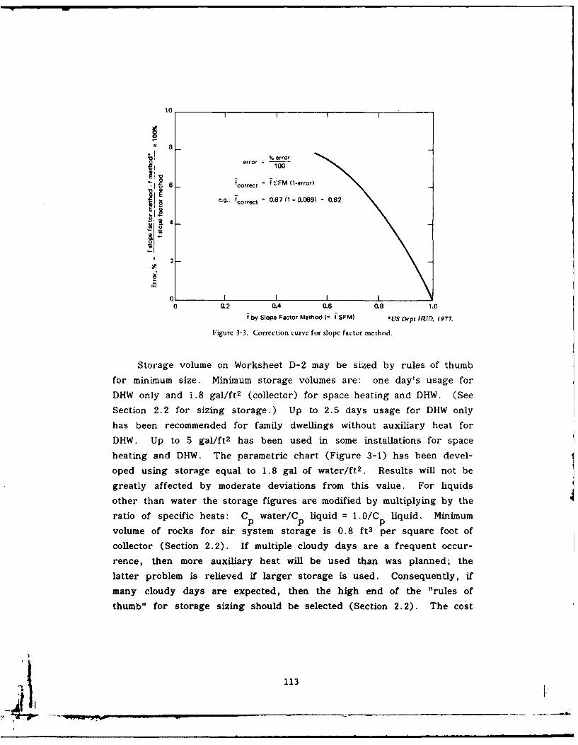
10
X 8! % error
error 100
"71 6 fcorrect = f vFM (1-error)
eg. fcorrect = 0.67 (1 - 0.069) 0.62
0
2
0 02 0.4 0.6 0.8 1.0
fby Slope Factor Method (= T SFM) *USDept HUI. 1977.
Figure 3-3. Correction curve for slope factor method.
Storage volume on Worksheet D-2 may be sized by rules of thumb
for minimum size. Minimum storage volumes are: one day's usage for
DHW only and 1.8 gal/ft 2 (collector) for space heating and DHW, (See
Section 2.2 for sizing storage.) Up to 2.5 days usage for DHW only
has been recommended for family dwellings without auxiliary heat for
DHW. Up to 5 gal/ft 2 has been used in some installations for space
heating and DHW. The parametric chart (Figure 3-1) has been devel-
oped using storage equal to 1.8 gal of water/ft 2 . Results will not be
greatly affected by moderate deviations from this value. For hquids
other than water the storage figures are modified by multiplying by the
ratio of specific heats: Cp water/Cp liquid = 1.0/Cp liquid. Minimum
volume of rocks for air system storage is 0.8 ft3 per square foot of
collector (Section 2.2). If multiple cloudy days are a frequent occur-
rence, then more auxiliary heat will be used than was planned; the
latter problem is relieved if larger storage is used. Consequently, if
many cloudy days are expected, then the high end of the "rules of
thumb" for storage sizing should be selected (Section 2.2). The cost
113
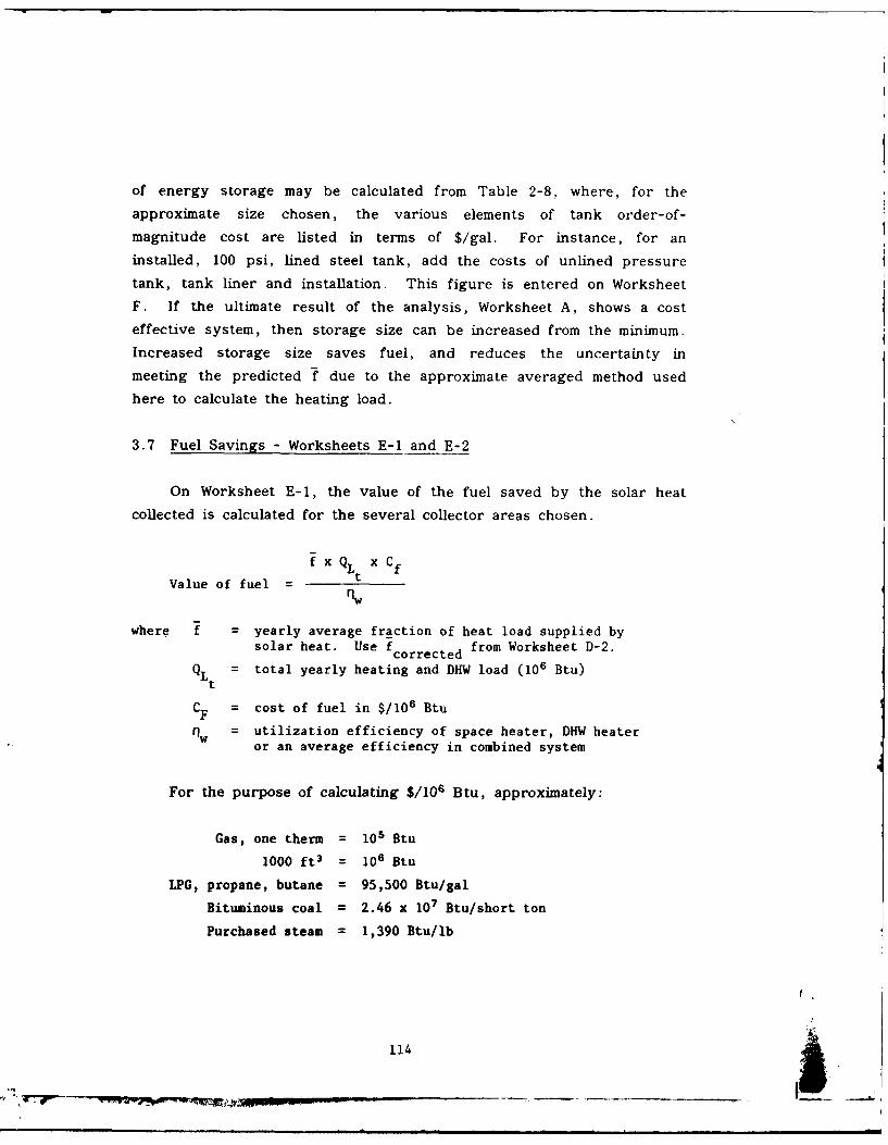
of energy storage may be calculated from Table 2-8, where, for the
approximate size chosen, the various elements of tank order-of-
magnitude cost are listed in terms of $/gal. For instance, for an
installed, 100 psi, lined steel tank, add the costs of unlined pressure
tank, tank liner and installation. This figure is entered on Worksheet
F. If the ultimate result of the analysis, Worksheet A, shows a cost
effective system, then storage size can be increased from the minimum.
Increased storage size saves fuel, and reduces the uncertainty in
meeting the predicted f due to the approximate averaged method used
here to calculate the heating load.
3.7 Fuel Savings - Worksheets E-1 and E-2
On Worksheet E-1, the value of the fuel saved by the solar heat
collected is calculated for the several collector areas chosen.
fxQ xC
Value of fuel = rnw
where f = yearly average fraction of heat load supplied bysolar heat. Use fcorrected from Worksheet D-2.
= total yearly heating and DHW load (106 Btu)
CF = cost of fuel in $/106 Btu
1w = utilization efficiency of space heater, DHW heateror an average efficiency in combined system
For the purpose of calculating $/104 Btu, approximately:
Gas, one therm = 105 Btu
1000 ft3 = 106 Btu
LPG, propane, butane = 95,500 Btu/gal
Bituminous coal = 2.46 x 10⁷ Btu/short ton
Purchased steam = 1,390 Btu/lb
114 i
Oil, No. 2 = 140,000 Btii/gal: 5.84 x 10⁶ BLu/bbl
No. 5 = 150,000 Btii/gal: 6.3 x 10r Btu/bbl
Electricity (at source which is fossil fueled) = 11,600 Btu/kwhI kwh = 3,413 Btih
The present worth of fuel saved can be calculated many different
ways. Two methods are shown in the following two sections.
3.7.1 Present Worth Using A Discount Factor and Fuel Differential
Escalation Rates. Historically this has been the method used and was
presented in the original version of this report. It is maintained here
for continuity and in the event it may be used again. The present
worth of 25 years fuel saved may be calculated by using Worksheet E-2,
or if standard fuel differential inflation rates (expected percentage
increase per year in fuel prices above general inflation rate) and 10%
discount factor are used, then a single multiplication given in note (2),
Worksheet E-1 will give the answer. Annual fuel inflation factors for
use on Worksheet E-1 or E-2 are given in Table 3-5a. Typically differ-
ential inflation factors of at least 7%-9% are used for fuels. If this
method is used, NAVFAC INSTRUCTIONS will provide the correct rates.
The figures from either Worksheet E-l, note 2 or from Worksheet E-2
are transferred to Worksheet A, column (y). Complete for each collec-
tor area under study.
3.7.2 Present Worth Using Fuel Escalation Rates Without the Dis-
count Factor. This is the current method to be used per NAVFACINST
11010.14M, 14 Dec 78. Solar systems shall be targeted to provide a
minimum of 25% of space heating load and 35% of DHW heating load.
Any system will be considered economic where the initial investment cost
is recovered in energy savings over the life of the facility (25 years).
Maintenance and replacement costs will not be considered in the analy-
sis. The discount factor shall not be applied. The fLlowing escalation
rates shall be used:
115
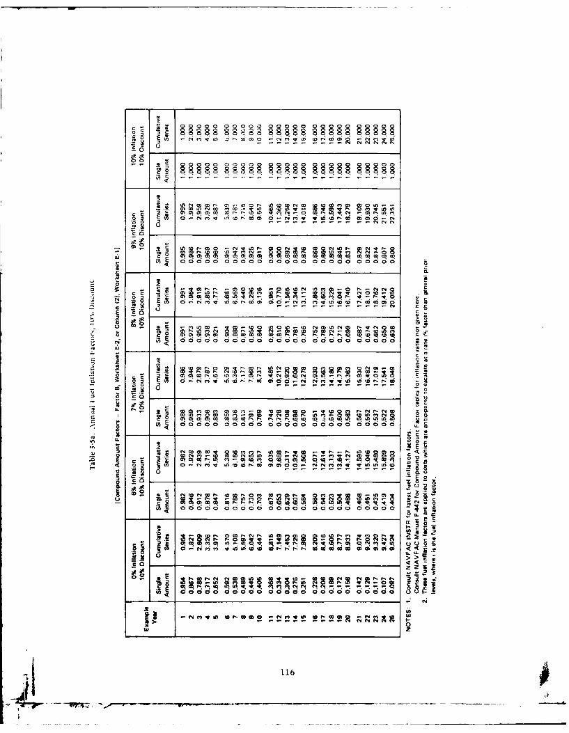
C0 0 0 00000 090 a 0~~
000000 000000
0000LON 0 'o Ln v b '
0 'Z
OR CCcq aq
414
N~- 0N D~~O' Q r N-Z 0 ErCr' '0
c 0b COE
-: L 20 F46 00 0 0 0 0000000000 0
Cr
Z - 0 COC - - -c,'r UCr-W -q- -r' 00re.9 .E
cc WE Q0) ) 00 m M to M t 0 (C0)0 0 (0 2*0 0-N!) NrC )0 w O m~ M ~LU mC0(.
c~ 0E.1 W- (4 co( -nr nO g1r lwW8 r
E. r> ;, )U o-t 11 r
g2 *E 4 O )U ZiZ (D l W q 4M izi44
E rl P tq . ~. . . . . _q V:lij0.0
eooco cooc qc c No e o 'Io _Q k
UU
> 0
z zC. N 116U t D 0N f
FY79 thru FY81 thru FY84 andFY80 FY83 Beyond
Fuel Oil 16% 14% 8%
Natural Gas & LPG 15% 14% 8%
Electricity 16% 13% 7%
The fuel inflation factors for this method are given in Table 3-5b.
Note that depending on when a project is initiated various factors will
apply. The present worth can be calculated in several steps as
follows:
(1) Calculate fuel saved per year from (1), Worksheet E-1 = A
(2) Project starts in FY80 = year 1
(3) Then next 3 years (FY81-FY83) savings = 4.992A (from Table
3-5b, 14% (fuel oil), year 4 amount)
(4) The remaining 21 years of economic life are at 8% escalation
(fuel oil, FY84 and beyond), therefore savings = 50.423A
(Table 3-5b, 8% (fuel oil), year 21 amount)
(5) Total savings = 50.423A + 4.992A = 55.415A or 55.4 times the
amount calculated in Worksheet E-l, note (1)
(6) These calculations can be done on Worksheet E-1, col (4) and
then transferred to Worksheet A, column (y)
If the reader uses different economic techniques at his duty sta-
tion (ECIP projects, etc.) then these worksheets need not be used.
Nevertheless, the methods proposed will provide a valid comparison of
solar systems and give a reasonable measure of their cost effectiveness.
3.8 Collector Temperatures - Worksheet E-1
Fluid temperature rise through collector is of interest and may be
calculated from:
117
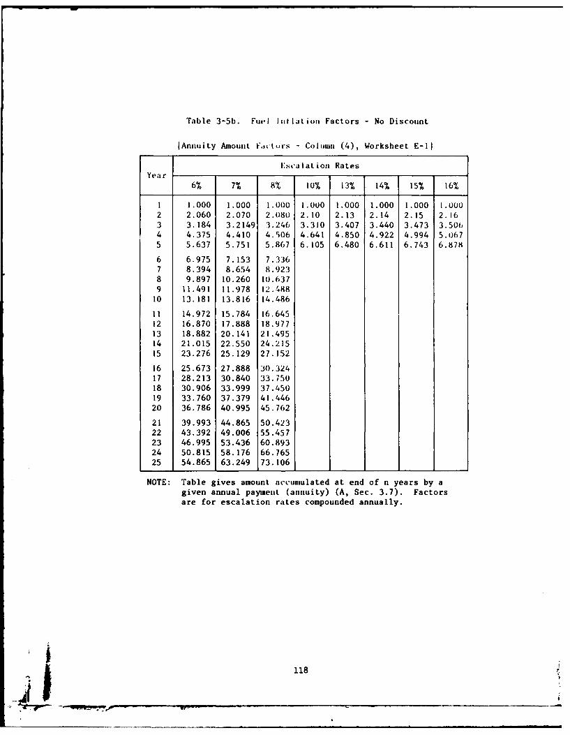
Table 3-5b. Fuel liiilation Factors - No Discount
[Annuity Amount Favturs - Column (4), Worksheet E-1I
Escalation RatesYear
6% 7% 8% 10% 13% 14% 15% 16%
i 1.000 1.000 1.000 1.000 1.000 1.000 1.000 1.0002 2.060 2.070 2.08o 2.10 2.13 2.14 2.15 2.163 3.184 3.2149 3.246 3.310 3.407 3.440 3.473 3.50t)4 4.375 4.410 4.506 4.641 4.850 4.922 4.994 5.0675 5.637 5.751 5.867 6.105 6.480 6.611 6.743 6.878
6 6.975 7.153 7.3367 8.394 8.654 8.9238 9.897 10.260 10.6379 11.491 11.978 12.48810 13.181 13.816 14.486
11 14.972 15.784 16.64512 16.870 17.888 18.97713 18.882 20.141 21.49514 21.015 22.550 24.21515 23.276 25.129 27.152
16 25.673 27.888 30.32417 28.213 30.840 33.75018 30.906 33.999 37.45019 33.760 37.379 41.44620 36.786 40.995 45.762
21 39.993 44.865 50.42322 43.392 49.006 55.45723 46.995 53.436 60.89324 50.815 58.176 66.76525 54.865 63.249 73.106
NOTE: Table gives amount accunulated at end of n years by agiven annual paymenit (annuity) (A, Sec. 3.7). Factorsare for escalation rates compounded annually.
118
41 i
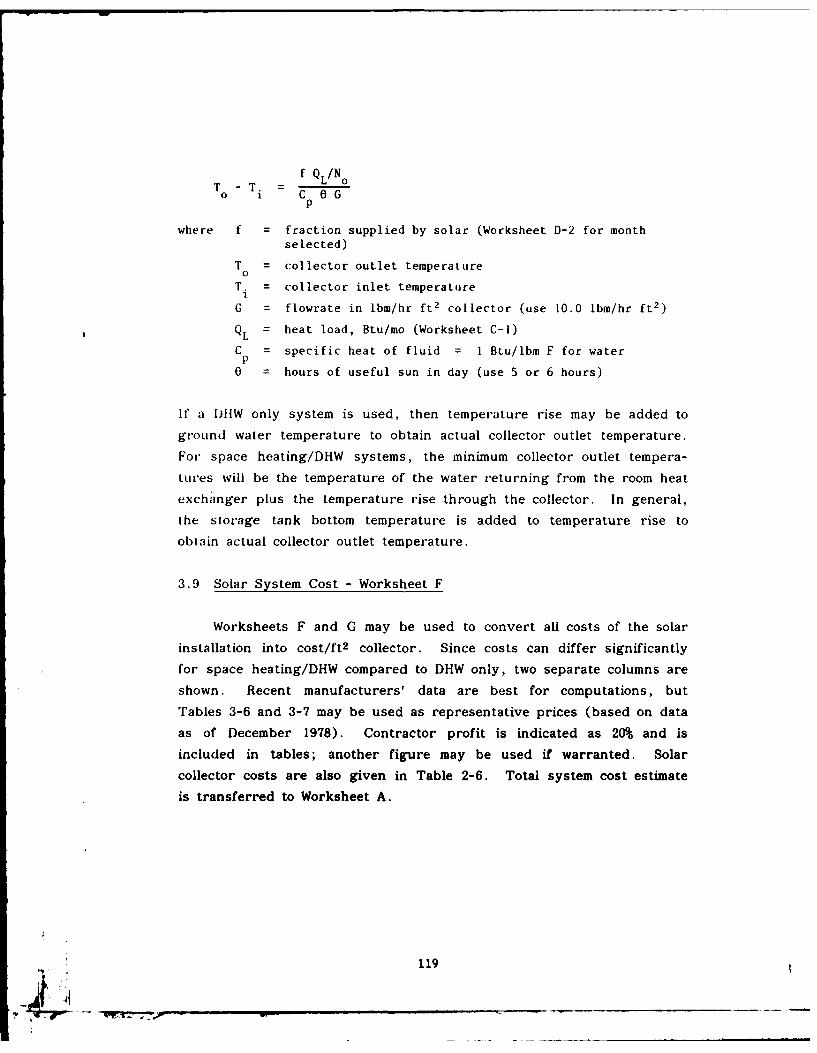
f Q LINo0T -T. - O
0 i C Gp
where f = fraction supplied by solar (Worksheet D-2 for monthselected)
T = collector outlet temperaLureo
T. = collector inlet temperature
G = flowrate in lbm/hr ft2 collector (use 10.0 Ibm/hr ft2 )
QL = heat load, Btu/mo (Worksheet C-I)
C = specific heat of fluid = 1 Btu/lbm F for waterP0 = hours of useful sun in day (use 5 or 6 hours)
If a DIiW only system is used, then temperature rise may be added to
ground water temperature to obtain actual collector outlet temperature.For space heating/DHW systems, the minimum collector outlet tempera-
tures will be the temperature of the water returning from the room heat
exchanger plus the temperature rise through the collector. In general,
the storage tank bottom temperature is added to temperature rise toobtain actual collector outlet temperature.
3.9 Solar System Cost - Worksheet F
Worksheets F and G may be used to convert all costs of the solar
installation into cost/ft 2 collector. Since costs can differ significantly
for space heating/DHW compared to DHW only, two separate columns are
shown. Recent manufacturers' data are best for computations, but
Tables 3-6 and 3-7 may be used as representative prices (based on dataas of December 1978). Contractor profit is indicated as 20% and is
included in tables; another figure may be used if warranted. Solar
collector costs are also given in Table 2-6. Total system cost estimateis transferred to Worksheet A.
119
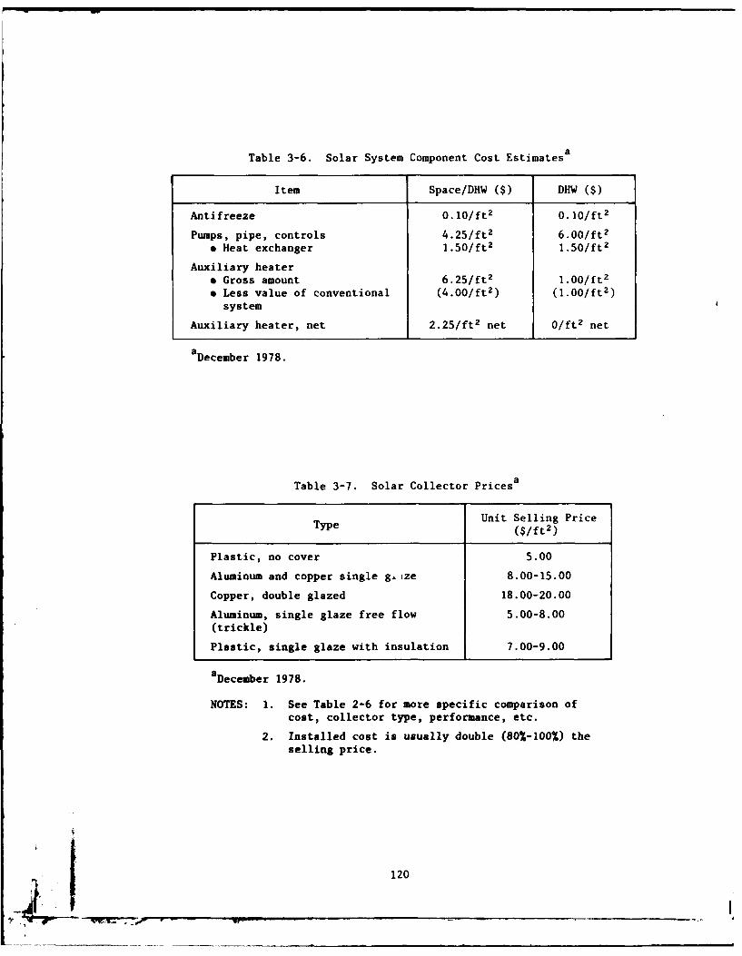
Table 3-6. Solar System Component Cost Estimatesa
Item Space/DHW Cs) DHW ($)
Antifreeze 0.10/ft 2 0.10/ft2
Pumps, pipe, controls 4.25/ft 2 6.00/ft 2
* Heat exchanger 1.50/ft2 1.50/ft2
Auxiliary heater* Gross amount 6.25/ft 2 1.00/ft 2
* Less value of conventional (4.00/ft2 ) (1.00/ft2 )
system
Auxiliary heater, net 2.25/ft2 net 0/ft 2 net
aDecember 1978.
Table 3-7. Solar Collector Pricesa
Type Unit Selling Price($/ft2 )
Plastic, no cover 5.00
Aluminum and copper single ge.ze 8.00-15.00
Copper, double glazed 18.00-20.00
Aluminum, single glaze free flow 5.00-8.00
(trickle)
Plastic, single glaze with insulation 7.00-9.00
a December 1978.
NOTES: 1. See Table 2-6 for more specific comparison ofcost, collector type, performance, etc.
2. Installed cost is usually double (80%-100%) theselling price.
120
3. 10 Additional Costs - Worksheet G
Worksheet G is a convenient checklist to collect costs associated
with converting to solar energy. On new building designs, good insu-
lation, weatherstripping, etc., will be called for to save energy, even
if solar heating is not adopted, thus the solar system should not be
burdened with these costs in new buildings. Costs are summed and
divided by collector area, then cost is transferred to Worksheet F.
Maintenance cost can vary from 1% of total systems cost in large instal-
lations to 5% in single residence DHW applications.
3.11 Sizing the Heat Exchanger for Space Heating
According to Klein, Beckman, and Duffie (1976):
The dimensionless parameter cLCmin/UA, has been found to
provide a measure of the si'e heat exchanger needed to supply
solar heat to a specified building. For values of c LCmin/UA
less than 1.0, the reduction in system performance due to too
small a heat exchanger will be appreciable. Reasonable values
of LC min /UA for solar space heating systems are between 1 and
3 when costs are considered. (This design method has been
developed) with &LCmin/UA equal to 2.0.
Cmin is heat capacity flowrate, which is the lesser of the two heat
capacity flowrates in the load heat exchanger; -L is effectiveness of
load heat exchanger and UA is overall heat loss coefficient of building
times the building area.
3.12 Air-Heating Collector Design - Worksheet H
The design procedure for air systems (Klein, Beckman, and
Duffie, 1977) is very similar to that for liquid systems - the same
worksheets may be used. Figure 3-4 gives the f-chart for this proce-
dure. The procedure was developed using an air flow heat capacitance
121
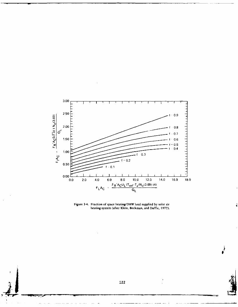
3.00
f 0.9
f -0.7
U 1.50 f0.6
f 0.5LLt 0.4
FLA
Figure 3-4. Fraction of space heating/DHW load supplied by solar airheating system (after Klein, Beckman, and Duffic, 1977).
122
rate of 2.87 Btu/hr ft2 'F (about 156 SCF/hr ft2). The performance of
systems having collector capacitance rates between 1.47 and 5.87 Btu/hrft2 F can be estimated by multiplying the values of FLAc{ [(c p)C/
F RAc1/2.8710.28 (Klein, Beckman, and Duffie, 1977). To calculate FR
see Duffie and Beckman (1974), Section 7.7. The rock bed storage
heat capacitance assumed was 19.6 Btu/ft 2 F. The performance of
systems with other storage capacities can be determined by multiplying
the dimensionless group FLAc by [(pVC pF A )/19.61-O.3 (Klein,
Beckman, and Duffie, 1977). The standard deviation of the yearly f by
this method from the computer simulated value was found to be 0.017
(Klein, Beckman, and Duffie, 1977).
A comparison of the f-charts for the liquid and air
systems indicates that, for the same values of [FIAc] and
[FLAc] the air system outperforms the liquid system particu-
larly for systems designed to supply a large fraction of the
heating load.... [Some reasons for this behavior are:] the
average collector fluid inlet temperature is lower for the air
system (and thus the collector efficiency is higher) than that
for the liquid system at times when . . . room air is circu-
lated through the collector and also because the more effec-
tive thermal stratification achieved in rock storage results
in lower temperature air going to the collector. Also since
no heat exchanger is required between collector and storage,
that inefficiency is avoided.
It cannot be concluded, however, that air heating systems
perform better than liquid systems. The overall collector
efficiency factor, FR, is ordinarily lower for air heaters.
As a result [FIAc] and [FLAc] are ordinarily lower and thus
the performance of an air system may be equivalent to or lower
than that of a liquid system, all else being the same.
(Klein, Beckman, and Duffle, 1977).
Sections 2.1.1 and 2.5 of this document discuss the relative merits
of air systems.
123v
3.13 Worksheets
A Job Summary
B Solar Collector Parameters
C-i Load Calculations
C-2 Demand Calculations - Domestic Water Heater
D-1 Monthly Solar Collection Parameters
D-2 Fraction of Load Supplied by Solar Heat
E-1 Value of Fuel Saved
E-2 Present Worth Analysis
F Solar System Cost Analysis
G Additional Cost Items Related to Use of Solar Heating
H Solar Air Collector System Design Summary
124
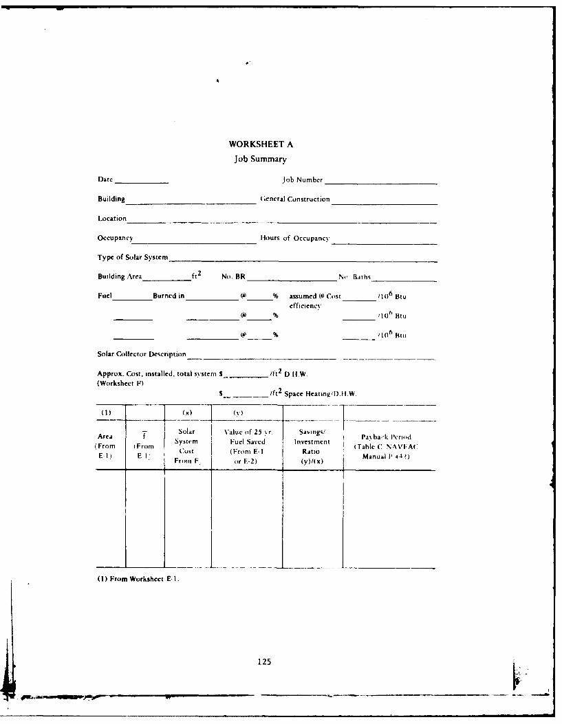
WORKSHEET A
job Summary
Date _______job Number______________
Building__________________ (encral Construction
Location
Occupancy Hours of Occupancy _______________
Type of Solar System __________________________________
Building Area ft 2 No. BR ______________No Bitths__________
Fuel Burned in _______() % assumed Cs) Cost /__ 06_ Btu
efficiency
__ __ __ _ _ __ __ __ _(a) %__ __ _ _ _ /106 Bill
Solar Collector Description ____________________
Approx. Cost, installed. total systemn S _________lt2 D.H-.W.
(Workshect F)S___________/ft 2 Space Heating'I).H1 W.
Area TSolar Value of 25 yr. Savings! ab.- co(From From Iytr Fuel Saved Investment: (Tab ha Ic '[-A('
E- -1, Cost (From E- I RAtioMaulP41)E*1 E-l From F, or E-)(y)/(x)MaulI44)
(1) From Worksheet El.
125
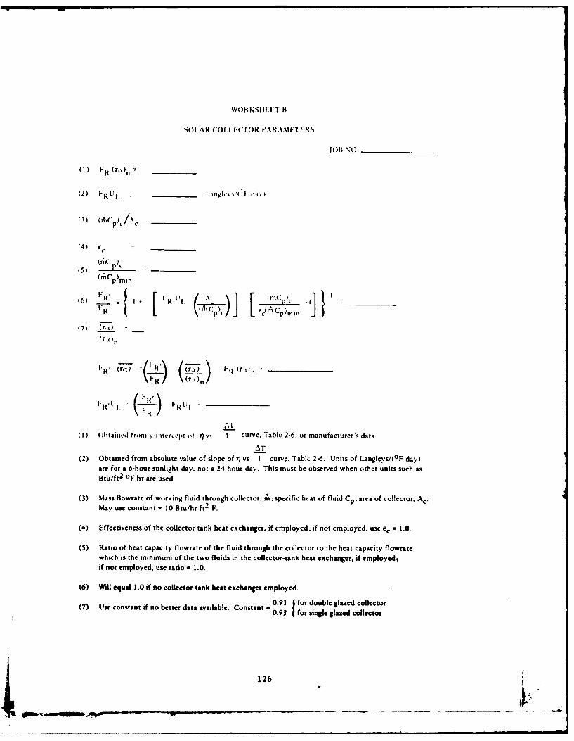
WORKSIII:IT H
SOLAR (OI.CtF(r PARAMIFTHS
(1) F (') n _ _ _ _
(2) FR U I IL.nglc% k' I" d.a
(3) (rhCp C/A
(4) e .
(5) n'P p_ _
(m('p mm
(6) 1 /IR' R I. X I 61 P i ~ _ _ _
EC( 1Cp)min
(7) (rq) =
I.R' (r- ) -
AI(1) Obtaimd from N -intcrccpt t t7 vs I curve, Table 2-6, or manufacturer's data.
AT(2) Obtained from absolute value of slope of rl vs I curve, Table 2-6. Units of Langleys/(°F day)
are for a 6-hour sunlight day, not a 24-hour day. This must be observed when other units such asBtu/ft 2
OF hr are used.
(3) Mass flowrate of working fluid through collector, rh; specific heat of fluid Cp; area of collector, A c .May use constant = 10 Btu/hr ft 2
F.
(4) Effectiveness of the collector-tank heat exchanger, if employed; if not employed, use cc = 1.0.
(5) Ratio of heat capacity flowrate of the fluid through the collector to the heat capacity flowratewhich is the minimum of the two fluids in the collector-tank heat exchanger, if employed;
if not employed, use ratio = 1.0.
(6) Will equal 1.0 if no collector-tank heat exchanger employed.
(7) Uf no better data available. Constant - 0.91 J for double glazed collectorconstant f 0.93 1 for single glazed collector
126
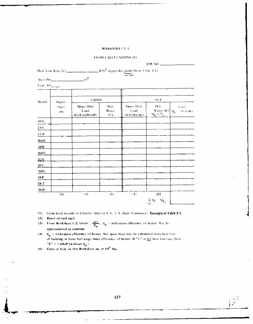
JOK NO _________
Ilat l.tos )(.t (i.) _______________ H/ft2 d.1grvc-di% gross (trii hid 3'~ 1-I
.\rcA(S~tor net
Yca r I Q
MIonth f)t-grLcc (.ROSSN l
I~%% Space I eat Ihot Space 11c.1 I lot
Loatl Watcr Load %katcr tWi
R =(l.)x(M )x(P) (1I') ('s')=(Rx ?I% o ~i _________
DAF _ _ _ _ _ _ _ __ _ _ _ _ _ _ _ _ _ __ _ _ _ _ _ _ _
JAN_ _ _ _ _ _ _ __ _ _ _ _ _ _ _ _ _ __ _ _ _ _ _ _ _ _ _
IA __ _ _ _ _ _ __ _ _ _ _ _ __ _ _ _ _ _ _ __ _ _ _ _ _
MAR __ _ _ _ __ _ _ _ _ _ _ _ _ _ _ _ _ _ _ _ _ _ _ _ _ __ _ _ _
AR ____ ___________ _____ _____
MAY _______
A U( ______ ________ ______ ______ _______ ______
(2 1aw o2) fu3l u4e(5
(3) 1 rom Work~uhcet C-2, Gross -nt iA - otilwtiion effivcn.% of licwitr \I it 1,
approxinratcd as constant.
4) jul I/at in efficienwN of heater Net spact: he.. max h e cActi1,,;et f romt heat 1,I
of bIu ild ing (tr frtom fuel u%;ig I timc% c hfit tent (~if hcot rr If " I. is nect lic.it fI o if c. ii
"V I1.MxP (without Y1,,
(5) Unit% oft hemr on this Work~hve: ire in 1 0 0 Iliti
127
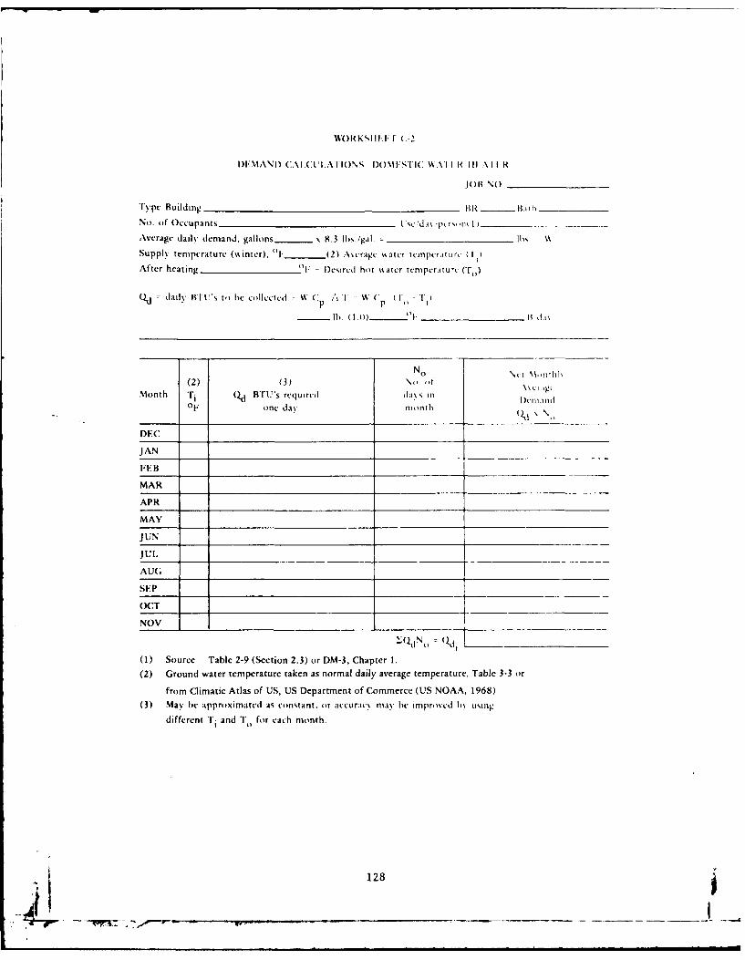
WORKSIIIKr (-2
)EMANI) (:.\I.(CA..AIIO\S I)()\I:SI(: IAI I I< III \11 R
OB \()
Type Building BR__ I __ iBi
No. of Occupants I'e 'da\ -pt iI,,n 1 )
Average dail\ demand, gallons - x 8.3 lbs/gil. lg
Supply temperature (winter), 1. _ (2) Ascragc %%ater tcmpcritur, l)
After heating o1. - Desircd hot water tcnipcritur (To)
()d = daily BTU's to be collectcd = W Cp A " " W C (I - '',)
lb (1.B) _l I ,1\
No \ t'lth
(2) (3) No. otMonth Ti Qd BTU's requircd da's in
OF one dav month
DEC
JAN
FEB
MAR
APR
MAY
JIUN
Jul,
AUG
SEP
OCT
NOV
-Q.N I 1 _ __
(1) Source - Table 2-9 (Section 2.3) or DM-3, Chapter 1.
(2) Ground water temperature taken as normal daily average temperature, Table 3-3 or
from Climatic Atlas of US, US Department of Commerce (US NOAA, 1968)
(3) May be approximated as constant, or accuraci may" be improved b\ u ing
different T i and T for each month.
128
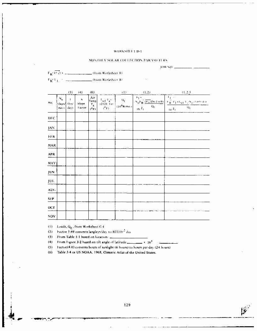
WOIKS1II. I I I)-I
MON1. IY SO I.A R (C( II I ITION PAR \\1 I I'I RN
.OH \0 _
I"R ' (T) (from Workshcct B)
I: R ' _ (from W)rkshccl Wt
(3) (4) (6) (I) ,2 1.25'1Air k
N(n I S Temp Tcfl I (" ).(3 19) I t ,it 1 4(I. vay,, (Iy/ Slope ra (21 2t-Ia) (TB -\'IFtoo.) davy Factor (0 F) 0) (10 /r -) (ft 2) 2 ,
D)C
JAN
FEB
MAR
APR
MAY
JUN
Jul.
AU;
SEP
O(CT
NOV
( I ) loads, Q1,' from Workshect C-I
(2) Factor 3.69 converts langleyIda. to Bill/t- da\.
(3) From Table 1-I based on location:
(4) From Figure 3-2 based on tilt angle of latitude __ * 100
(5) Factor(4.0) converts hours of sunlight (6 hours) to hours per da. (24 hours)
(6) Table 3-4 or US NOAA, 1968, Climatic Atlas of the United States.
4 129
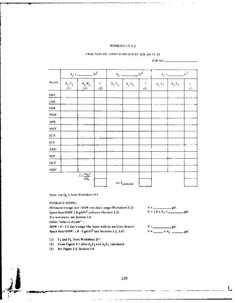
WORKSIIIT Di1-2
FRACT~iION 01; LOAD) SLTPI'.lI.D BYSOLAR hI-Al
JO)B wO______________
A ___t___ t 2 11A _____ft
2 A _H2___
Mnh AC I-I cFl Ac FA A C - A, I-~ ACI____1_ ( 0(1 (2) (2) ______
DEC
JAN _______
FE B
MAR
APR
MAY _ _ __ _1 _
JUN _______ ___ __
AUG;
SEP
OCT
1 ~ (3) fcurrected
Note: use QL' from Worksheet I)-)
STORAGE SIZING:
Minimum storage size - DIIWv one days' usage (Worksheet C-2) V = -_____ gal.
Space heat/DH-W 1.8 gal/ft2 collector (Section 2.2) V =1.8 x A, = -_____gal.
For non-water, see Section 3.6
other "rules of thumb" -
DFIW 1.0 - 2.5 day's usage (the latter with no auxiliary heater) V = _______gal.
Space hcat/DiW: 1.8 - 5 gal/ft 2 (see Sections 2.2, 3.6) V = _ _x Ac - gal.
(1) F1I and F L from Worksheet D-l1
(2) From Figure 3-1 after ACE, and AcFL calculated
(3) See Figure 3-3, Section 3.6
130

WORKSIIFFT F-l
VA .. I- OF FUI:1. SA\V I 1)
JOB NO.
(3)
(I) (2) (4)
(From Value of Present Worth ot 25 rs Present Worth of 25 yrs.
Area From on Worksheet C-0) Fuel Saved Fuel at ___%/yr. Fuel at _%/yr.
Worksheet 1)-2 Supplied (BTU x
(0t) by Solar 106Tr per Year Inflatton Rate and 10% Inflation Rate
A Discount Rate, Tabc 3-5a No Discount, Table 3-5b
Sx QItxF -(1) A = Value of fuel saved , use fcorrected from Worksheet D-2
CF = cost of fuel, $/10 6 BTU
77w = Utilization efficiency of furnace, DIIW heater or compromise 77w. (Worksheet A)(2) Present Worth = 18.049 x value of fuel saved/yr - 7% Inflation I 10% Discount
20.050 x value of fuel saved/yr - 8% Inflation See Table 3-5a, Section 3.7.1
25.000 x value of fuel saved/yr - 10% Inflation
or use Worksheet E-2. Note: Consult NAVFAC Instr for latest fuel inflation rates.
Transfer figures to Worksheet A.
(3) Or Qdt from Worksheet C-2 for DIIW only systems.
(4) No discount method (see Section 3.7), Table 3-5b, use either column (2) or (4), not both.
Transfer figures to Worksheet A.
COLLECTOR TEMPERATURES
fQL/NoTo'Ti GC p0 Ac -
QL from C-I for month selectedNo number of days in month
C specific heat of fluid
0 number of hours of usable sun in day, use 5 or 6 hours
G is flowrate in Ibm/ft2 hr, use (10 Ibm/hr ft2 )
f from D-2 for month selected.
131
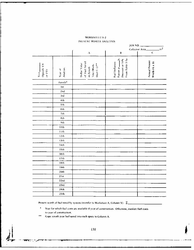
WORKSIII.I .-2
PRESENT WORTII ANALYSIS
JOB NO.
Collector Area ft2
A B C
' -- . -"
Zeroth*
Ist
2nd
3rd
4th
5th
6th
7th
8th
9th
10th
1 th
12th
13th
14th
15th
16th
17th
18th
19th
20th
21st
22nd
23rd
24th
25th
Present worth of fuel saved by system (transfer to Worksheet A, Column Y)
. Year for which fuel costs are available if year of construction. Otherwise, escalate fuel costs
to year of construction.0 Copy zeroth year fuel saved into each space in Column A.
132
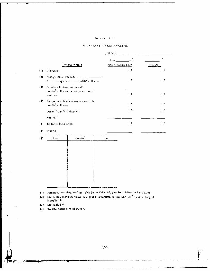
',(IlR I~ I \I COS I ANALYS IS
Item I~esripttpan licating'II1W% 111W Onktt
(2) Storage tank. intaldilI ________________
S _ /gal gail/ftt2 ,l(t,1 11 11t
(3) Auxiliar\ lieating unit, installctl
cost/tt2 Co)lltr. net ()f eonvvwntinl
unit Ctt1112
(3) Pumps, pipe. butt exchangers, controls
cost/ft2 collectorA212
Other (fromt W rkshut (0 11 ) 1
Subtotal __________ _________
(1) Collector installation Ift 2 H
(4) iOTA 1.______________ ______________
(1) Manufacturer's data, or from Table 2-6 or 'rablc 3-7, plus 80 to 100% for installation
(2) see 'rable 2-8 and Worksheet D-2, plus S.10 (antifreeze) and $1.50/ft 2 (heat exchanger)if applicable.
(3) See Table 3-6.
(4) Transfer totals to Worksheet A.
133
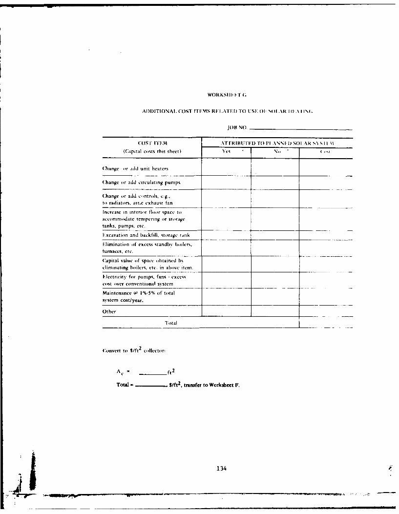
WORKSII FI"(;
AI)I)ITIONAI. COST rr.MS R.I . TI.D TOUSE O1" , .R I I.A1\1(.
JOB NO.
COST ITEM \rrRIBUT E) r ( l' ..\r I D SOI AR S'% S II \
(Capital costs this sheet) es No C .,
Change or add unit heaters
Change or add circulating pumps
Change or add c,)ntrols, e.g.,
to radiators, attic exhaust fan
Increase in interior floor space to
accomnmodate tempering or storagetanks, pumps, etc.
Excavation and backfill. storage tank
Elimination of excess standb\ boilers,
furnaces, etc.
Capital value of space obtained b
eliminating boilers, etc. in above item.
Ilcctricity for pumps, fans -excess
cost over conventional sy'stem
Maintenance a 1%-5% of totalsystem cost/year.
Other
Total
(onvert to S/ft2
collector:
A c = _ ft2
Total = Sift 2 , transfer to Worksheet F.
_j _ ___134_
?d '-
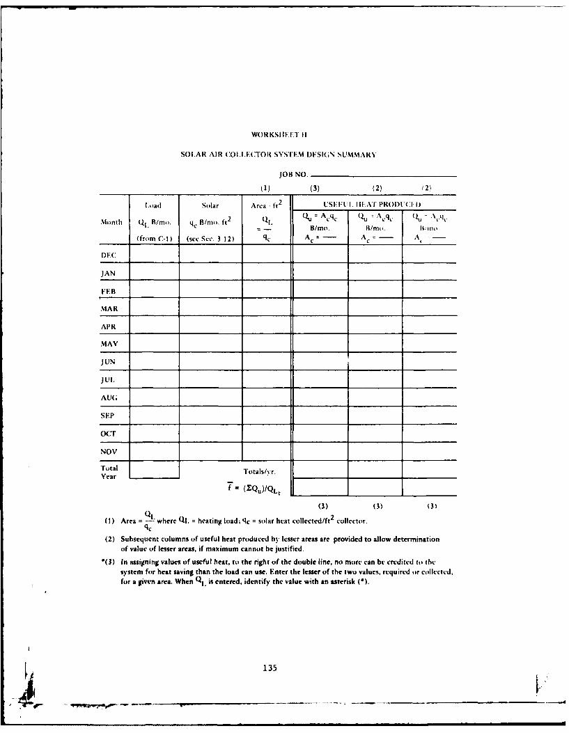
WORKSI IET II
SOLAR AIR COLLECTOR SYSTEM DESI(;N SUMMARY
JOB NO.
_) (3) (2) (2)
Load Solar Area - ft 2 USEFUEL. I.IAT PROI)U(C I)
Month Ql' B/mi. q, B/mo. ft2 (. QQ. A q q (), - .,q,- - B/mo. B/mo. I'Jr Ino
(from C-1) (se Secc. 3 12) q, Ac =
_ A AC A, _--
DEC
JAN
FEB
MAR
APR
MAY
JUN
Jul.
AUG
SEP
O(CT"
NOV
Total Totals/yr.Year
f= ('Qu)/QLt
(3) (3) (3
(1) Area = where QL = heating load; qc = solar heat collected/ft2 collector,qc
(2) Subsequent columns of useful heat produced by Icsscr areas are provided to allow determinationof value of lesser areas, if maximum cannot be justified.
'(3) In assigning values of useful heat, to the right of the double line, no more can be credited to thesystem for heat saving than the load can use. Enter the lesser of the two values., required or collected,for a given area. When Qi. is entered, identify the value with an asterisk ().
135
4.0 EXAMPLE PROBLEMS
See Section 3 for instructions on preparing Worksheets.
4.1 Discussion of Example 1
Space and Water Heating System for Family Housing (see Section
4.1.1). Preliminary job data are entered on Worksheet A. The first
step in the analysis (Worksheet B) is to determine the y-intercept and
slope of the collector efficiency curve. A single glazed, all copper
roUbond collector with selective coating was chosen. The y-intercept
and slope were taken directly from Table 2-6, Collector #22. They are
0.77 and 1.72 Langleys/°F/day, respectively. Note absolute value of
slope used. Next, the recommended figure of 10 Btu/ft 2 IF hr is
selected for (nC p)c /A , line 3, Worksheet B. Since there will be no
heat exchanger between collector and tank fluids, the next three
factors equal 1.0. Line 7, Worksheet B is equal to 0.91 for a single
glazed collector. Then Fl(ta) and FI UL are calculated and transferred
to Worksheet D-1.
The next step is to determine the heat load or demand. This is
usually done by conventional methods of estimating heat losses from
buildings and water usage per occupant. Table 3-1 provides estimates
of building heat loss rates and other sources for calculating this param-
eter are given in Section 3.3. In Example 1, Worksheet C-1, the fuel
usage was calculated using the Btu/ft 2 degree-day method. First a
rough estimate for the average family house at Port Hueneme was
obtained from 1 month's usage of gas for all housing divided by the
number of degree days in the month and the total number of square
feet in the housing area. This figure (QL = 29.Btu/ft2dd) included hot
water heating. The estimated hot water use for a 3-bedroom 2-bath
home gave a figure for hot water use per square foot which was then
subtracted from total use for the 1,500 ft2 home. Resulting figure gave
space heating fuel use as 21.5 Btu/ft 2 dd. This gross figure was multi-
plied by furnace efficiency of 0.7 to get 15.0 Btu/ft2 dd net. Net heat
is that which must be supplied by solar heat. Gross heat represents
136
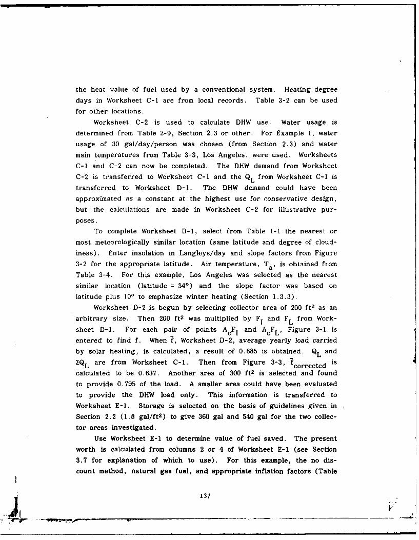
the heat value of fuel used by a conventional system. Heating degree
days in Worksheet C-i are from local records. Table 3-2 can be used
for other locations.Worksheet C-2 is used to calculate DHW use. Water usage is
determined from Table 2-9, Section 2.3 or other. For Example 1, water
usage of 30 gal/day/person was chosen (from Section 2.3) and water
main temperatures from Table 3-3, Los Angeles, were used. Worksheets
C-i and C-2 can now be completed. The DHW demand from Worksheet
C-2 is transferred to Worksheet C-i and the Q L from Worksheet C-i is
transferred to Worksheet D-1. The DHW demand could have been
approximated as a constant at the highest use for conservative design,
but the calculations are made in Worksheet C-2 for illustrative pur-
poses.
To complete Worksheet D-1, select from Table 1-1 the nearest or
most meteorologically similar location (same latitude and degree of cloud-
iness). Enter insolation in Langleys/day and slope factors from Figure
3-2 for the appropriate latitude. Air temperature, T a, is obtained from
Table 3-4. For this example, Los Angeles was selected as the nearest
similar location (latitude = 340) and the slope factor was based on
latitude plus 10' to emphasize winter heating (Section 1.3.3).Worksheet D-2 is begun by selecting collector area of 200 ft 2 as an
arbitrary size. Then 200 ft2 was multiplied by F I and F L from Work-
sheet D-1. For each pair of points A cF Iand A cF L'Figue31i
entered to find f. When ?, Worksheet D-2, average yearly load carried
by solar heating, is calculated, a result of 0.685 is obtained. QL and
7_are from Worksheet C-i. Then from Figure 3-3, f corrected iscalculated to be 0.637. Another area of 300 ft2 is selected and found
to provide 0.795 of the load. A smaller area could have been evaluated
to provide the DHW load only. This information is transferred to
Worksheet E-1. Storage is selected on the basis of guidelines given in
Section 2.2 (1.8 gal/ft 2 ) to give 360 gal and 540 gal for the two collec-
tar areas investigated.
Use Worksheet E-1 to determine value of fuel saved. The present
worth is calculated from columns 2 or 4 of Worksheet E- 1 (see Section
3.7 for explanation of which to use). For this example, the no dis-
count method, natural gas fuel, and appropriate inflation factors (Table
137
3-5b) are used. Therefore, column (2) is not used nor Workshe-t E-2.
Assume project starts in FY80, then compute column (4) as example
shown in Section 3.7.2 (i.e., 55.415 times amount in column 1).
Fluid temperature rise through the collector is calculated on Work-
sheet E-l for a selected month. Calculation may be repeated for each
month desired. For the month of December and 200 ft 2 collector area, f
is 0.5, QL is 9.31 x 10⁶ Btu/mo, G is 10 lb/hr ft2. Using the formula
on Worksheet E-1, a temperature rise of 12.5 0 F is found. This is the
order of magnitude temperature rise most desired. Note that, using the
same formula, the AT could be fixed at, say 100F, and a flowrate, G,
calculated. Sizing of pump, pipe, and collector tube diameters for low
pressure drop is based on flowrate G (see Section 2.9).
Worksheet F may be used to calculate total installed solar system
cost/ft 2 , or, the manufacturer's price for complete systems, installed,
based on per square foot of collector area, may be used. On Worksheet
F, collector cost may be obtained from Table 3-7, Table 2-6, or manu-
facturers' quote may be used. Tank volume is based on 1.8 gal/ft 2
collector for space heating/DHW. The installed price of the insulated
tank was taken from Table 2-8 (here $3.50/gal). Up to 5 gal/ft 2 may
be specified for space heating/DHW. DHW-only storage may equal one
or more days expected consumption. Other costs may be priced from a
detailed design or figures from Table 3-6 may be used. Other costs
listed on Worksheet G are neglected for this example for simplicity.
Worksheet A may now be filled in with the values from the various
worksheets. When this is done the solar system using 200 ft 2 of collec-
tor is found to be cost effective in that it saves more in fuel than it
costs to install. The 300 ft 2 system is not cost effective. This fact
may also be seen from Worksheet D-2 for the 300 ft 2 system. There
are 6 months where the fraction of load supplied by solar, f, is equal
to 1.0 and some of the other months are close to 1.0. Much of this
system is not being utilized; that is, it does not result in fuel savings
for those months when more solar energy is available than can be used.
138
.-- - m" " r - .t--.- " - w ..
The next step, for this example, would be to evaluate a 250 ft2 system
to see if it is more or less cost effective than the 200 ft 2 system. Also
a given system can usually be made more cost effective by installing
insulation to reduce the building heat loss rate. This should always be
considered.
4. 1 .1 Example 1I Worksheets.
139
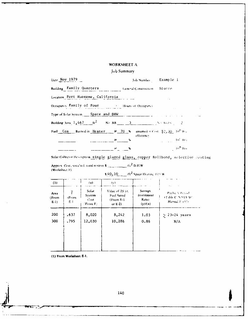
WORKSHEET A
Job Summary
L),t, Nov 1979 Job Number t Example I
Building Family Quarters (,cnc-ral Construction Stucco
Location Port Hueneme, California
Occupan,. Famnily of Four - Ilours iff Occupain,
Type of Solir Systemn Space and DHW
Building ~rra 12467-- t[ No RR 32__ , j~;
Fuel Gas -Burned in Heater (a) 70 % assumcd a,-a.t 2. 30 11"it,"
Solar Collector Dt-'.riptiron single -lze-s, cop -r Rolibond, selective coating
Approx COst, nsto.Olcd, total s\ stem .$_____ li 2 D.1.
(Workshe4 t F'is-40.l10 - /ft 2 Space lljin hI) 1,W
Area T Solar Value oif 25 yr. Savings. Pij i'% h.(From rom Isystem Fuel Saved Investment C\'i-
E-1) F., Cost (From E-1 RAtio M, nal I V IFrom F; or E-2) (y)/( x) - _____
200 .637 8,020 8,242 1.03 I".23-24 years
300 .795 112,030 10,286 0.86 N/A
(1) From Worksheet E-1.
1406
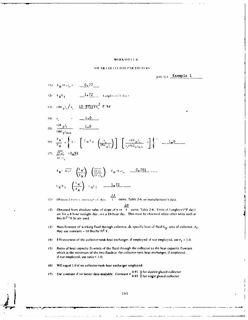
WORK111 Il K
1,0)1 %R kC()1. 1 VC I ()IR P \R.\ N1 I I R,
JOlh() Example 1
(1) (r)0.77
(2) IRL 1 1.72 F 1
2(3) P 10 BTU/ft_ F hr
(4) - 1.0
(5) ( p)c 1.0
(6) H.R - ij I I l 6CP
1. I ( mCp
(7) r L
T)
0, 1
(r I
I ('. , I R' (T, I R (TO 0 701V ((T ')n
F IR) 1 1 72IR' V I ( I.- R l
Al
( 1) Ohtaill., f',,,TI ,,ur,, r, ,f r/v I curv. Table 2-6, or manufacturer's data.
AT
(2) Obtained from absolute value of slope of ? vs I curve, Table 2-6. Units of l.angleys/('F day)are for a 6-hour sunlight day, not a 24-hour day. This must be observed when other units such asBtu/ft 2 (F hr arc used.
(3) Mass flowrate of working fluid through collector, t;; specific heat of fluid Cp; area of collector, Ac.May use constant = 10 Btu/hr ft2 F.
(4) Effectiveness of the collector-tank heat exchanger, if employed; if not employed, use f, = 1.0.
(5) Ratio of heat capacity flowrate of the fluid through the collector to the heat capacity flowratewhich is the minimum of the two fluids in the collector-tank heat exchanger, if employed;if not employed, use ratio = 1.0.
(6) Will equal 1.0 if no collector-tank heat exchanger employed.
(7) Use constant if no better data available. Constant = 0.91 for double glazed collector0.3for single glazed collector
4 141
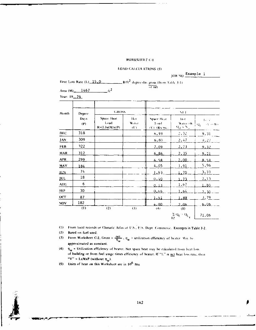
WORKSIIEi-T (:-I
ILOAD CAILCULATIONS (5)
JOB NO Example 1
heat I.oss Rate (I.) 15.0 B/f1 2 d,-grcc-da% gross (from Iai" 3-1)or net
Area (M) 1467 ft 2
Year: 19.2.9
Month Degree (.ROSDays Space Ileat IHot SpacI fihi[ hT 1
(P) l.ad Wtcr I oad \atcr W \. r .R=(L)x(M)x(P) (1 - i\'uiRx ?755 ld ' \ 7___% -
DEC 318 6.99 2.32 9.31
JAN 309 6.80 2.47 9.27
FEB 322 7.09 2.23 9.32
MAR 312 6.86 2.35 9.21
APR 299 6.&8 2-00 1 .. 5
MAY 184 4.05 1.91 5.96
IUN 74 1.63 1.70 3.33
JUL 18 (0.4_0 1-73 2.13AUG 6 O_ 1 3_ 1.67 1. 80
SEP 30 0, 66 i,154 u. %0 06OCT 87 -81 3.-8 .79
NOV 182 [_______________(1) (2) (3) (4) (5)
1 ( 1 ( 1i 7 1 . 0 6
12 ___
(1) From local records or Climatic Atlas of 1'.S. U.. Dept. Conmcrcc. Excerpts in Table 3-2.(2) Based on fuel used.(3) From Worksheet C-2, Gross = n , = utili/ation efficiency of heater \1.i bv.
approximated as constant.
(4) i"w = Utilitation efficiency of heater. Net space heat may be calculated tront heat lossof building or from fuel usage times efficiency of heater. If "I.- is net heat loss rate, thcico"V" = I.xMxP (without rw).
(5) Units of heat on this Worksheet arc in 106 Btu
142

WORKSII. II (2
I)FI-ANI) ( X.\L(+Ul.AlIO'0 J)(OM'IIS HC I. lI R I I I \ 1 R
08 \) Example 1
vp.c Building- Quarters 1 3 HIth 2
N, ,,j iupint 4 16%'d' pt r,,ii 30
.\\cr,igc daLi iciand, gallons 120 \ 83 ihN d. 996 lh_ \\
Suppl\ ii m lriturc (\%intcr). l..e.ow (2) A\(ragc \%itcr cmnpcratur, i I
\tcr hcating- 130 01' l)- sir d hot %\socr rtcperaturt (To)
B- l. II \i c cilectcd W (\. I k l -T1
For Jan. 996 I (iL) (130-oI- 0.75x10 5
55)
No(2) (3) No. of
Monlth Ti 0 t, 1311's required da's in I I )i,OF one day month
E(: 55 0.75 x 10⁵ 31 2.32 x 10⁶
_lAtN 50 0.80 x 10⁵ 31 2.47 x 10⁶
Il.B 50 0.80 x 10⁵ 28 - _ 1 ]06_
MAR 54 0.76 x 10⁵ 31 2.35 x 10
APR 63 0.67 x 10⁵ 30 2.00 x 10 6MAY 68 0.62 x 10⁵ 31 .91 x 106
JUN 73 0.57 x 10⁵ 30 1.70 x 10
JUL 74 0.56 x 10⁵ 31 1.73 x 10⁶
AUt; 76 0.54 x 10⁵ 31 1-67 x 106Sl:P 75 0.55 x 10⁵ 30 1.64 x 10⁶
OCT 69 0.61 x 10⁵ 31 6
NOV 105 in _2x.06 x 106
E(,N Q jd 23.96 x 10⁶(1) Source Table 2-9 (Section 2.3) or DM-3, Chapter 1.
(2) Ground water temperature taken as normal daily average temperature, Table 3-3 or
from Climatic Atlas of US, US Department of Commerce (US NOAA, 1968)(3) May be approximated as constant, or accurac. may e improved hY t1%111g
different Ti anti T. for each month.
jl 143
r- --V. -- --...
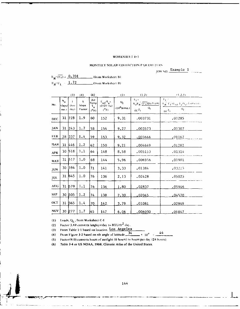
WORKSIII< 1)-I
MONTIl I.Y SOLAR (OIL(TION P.\RA\lI-I'[ ,
JoIA w Example 1
IR ' 0. 701 (from Worksheet B)1R, I. 1.72 (trom Workshec B)
(3) (4) (6) (1) (1.2) (1.2.5
No Air T -* QNo I S Temp Trcf-la ql N "F (T' -- (Q I (
Mo. (day%/ (IV" Slope Ta (212F-Ia) o ( r. ) wi (I"
mo.) da) factor (F) (OF) ( IO ) (ft.2) ( 21 (11
DFC 31 228 1.9 60 152 9.31 .003731 .01285
JAN 31 243 1.7 58 154 9.27 .003573 .01307
PEB 28 337 1.4 59 153 9.32 .003666 .01167
MAR 31 446 1.2 62 150 9.21 .004649 .01282
APR 30 518 1.1 64 148 8.58 .005153 .01314
MAY 31 517 1.0 68 144 5.96 .006956 .01901
JUN 30 594 1.0 71 141 3.33 .01384 .03225
Jul 31 645 1.0 76 136 2.13 .02428 .05025
AU(; 31 579 1.1 76 136 1.80 .02837 .05946
SEP 30 505 1.2 74 138 2.30 .02045 .04570
OCT 31 365 1.4 70 142 3.79 .01081 .02949
NOV 30 277 1.7 65 147 6.06 .006030 .01847
(1) Iloads, Q1 ., from Worksheet (-1
(2) Factor 3.69 converts langleys/day to BTU/ft2 day
(3) From Table 1-1 based on location; Los Angeles34 44
(4) From Figure 3-2 based on tilt angle of latitude 34 + 10° 44
(5) Factor(4.0) converts hours of sunlight (6 hours) to hours per day (24 hours).
(6) Table 3-4 or US NOAA, 1968, Climatic Arias of the United States.
14441 _ __ _ _ _ _
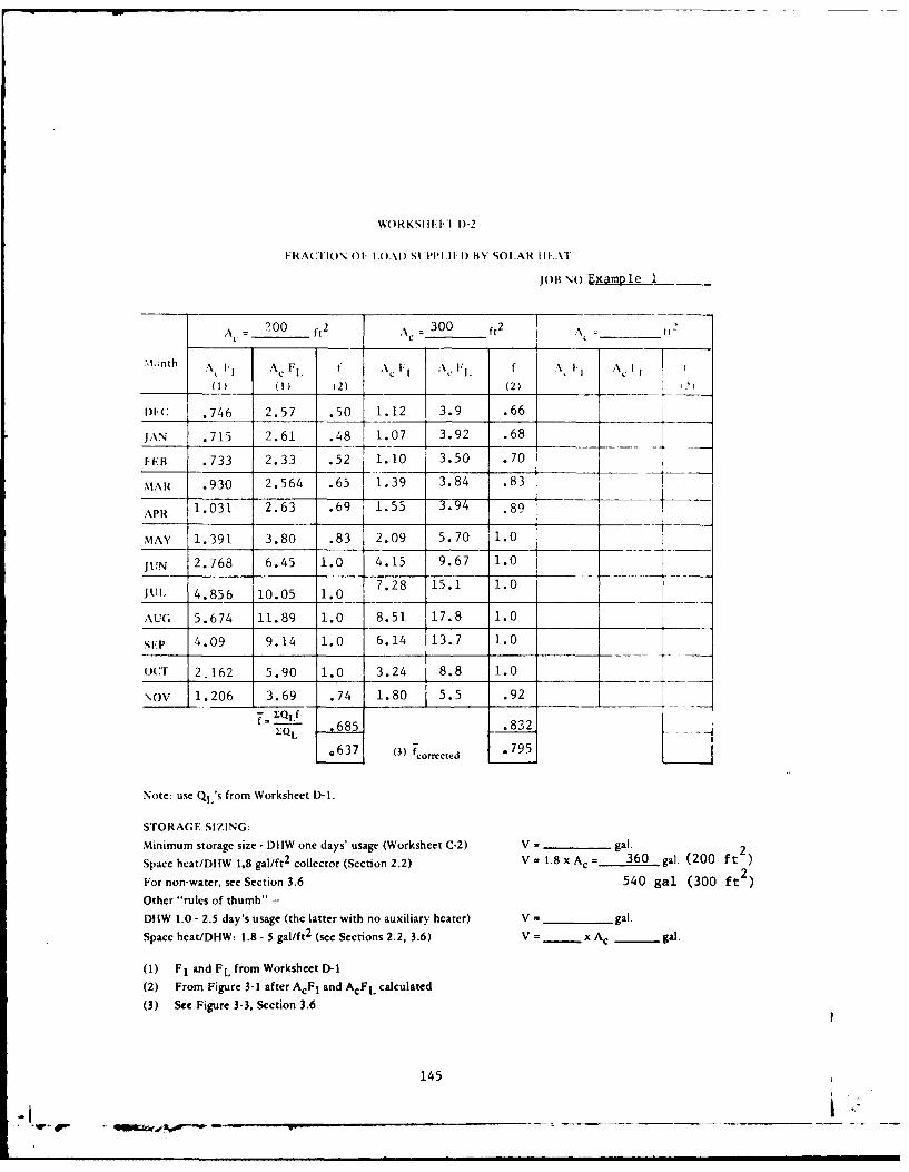
WORKSIII[I I)-2
FRAC'I ION Of ILOAD) St PPII 1I) BY SOLAR III'Al
JOB NO.Example 1
200 ft2 Ac 300 2 1Ac -= = ____"____ t' ________
.lnth " i.; Ac F1, f A l , F f .X t AI.
_____ (1) (1) (2) (2) J
lIC .746 2.57 .50 1.12 3.9 .66
J\N .715 2.61 .48 1.07 3.92 .68
FH .733 2.33 .52 1 .0 3.50 .70
IAR .930 2.564 .65 1.39 3.84 .83
APR 1.031 2.63 .69 1.55 3.94 .89
MAY 1.391 3.80 .83 2.09 5.70 1.0 1JUN 2.768 6.45 1.0 4.15 9.67 1.0 -
JUl. 4.856 10.05 1.0 7.28 15.1 1.0
AUG 5.674 11.89 1.0 8.51 17.8 1.0
SET 4.09 9.14 1.0 6.14 13.7 1.0
OCT 2,162 5.90 1.0 3.24 8.8 1.0
NOV 1.206 3.69 .74 1.80 5.5 .92f = _QLf
QL 685 .832
(3) fcorrected
Note: use Ql's from Worksheet D-1.
STORAGE SIZING:
Minimum storage size - DHW one days' usage (Worksheet C-2) V = gal. 2
Space heat/DEIW 1.8 gal/ft2 collector (Section 2.2) V = 1.8 xA c = 360 gal. (200 ft )For non-water, see Section 3.6 540 gal (300 ft2)Other "rules of thumb" -
Df1W 1.0 - 2.5 day's usage (the latter with no auxiliary heater) V = - gal.
Space heat/DHW: 1.8 - 5 gal/ft 2 (see Sections 2.2, 3.6) V =- x Ac gal.
(1) F1 and FL from Worksheet D-I
(2) From Figure 3-1 after AcF, and AcFL calculated
(3) See Figure 3-3, Section 3.6
145
. - ,- qq gcr . --,, - -- -- - - - - - -- - - - - - - - - - - -- ---- _ _

WORKSHEET E-1
VALUE OF FUEL SAVED
JOB NO. tExaapl -11
(3)
(1) (2) (4)f Qt (From Value of Present Worth of 25 vrs. Present Wrth of 25 vrs.
Area From Fraction Worksheet C-1) Fuel Saved Fuel at __%/yr. Fuel at __%/vr.Worksheet D-2 Supplied (BTU x
(ft2 ) by Solar 106 /yr) per Year Inflation Rate and 10% Inflation RateA Discount Rate, Table 3-5a No Discount. Table 3-5b
200 .637 71.06 $148.73 - $8241.87
300 .795 71.06 $185.62 - $10,286.13
(1) A = Value of fuel saved =7xQLtxCF - Z() ue= w ,use fcorrected from Worksheet -2
CF = cost of fuel, $1,06 BTU
77w = Utilization efficiency of furnace, DHW heater or compromise Iiu. (Worksheet A)(2) Present Worth = 18.049 x value of fuel saved/yr - 7% Inflation
20.050 x value of fuel saved/yr - 8% Inflation See Discoun t25.000 x value of fuel saved/yr - 10% Inflation See Table 3-a, Section 3.7.1
or use Worksheet E-2. Note: Consult NAVFAC Instr for latest fuel inflation rates.
Transfer figures to Worksheet A.
(3) Or Odl from Worksheet C-2 for DHW only systems.(4) No discount method (see Section 3.7), Table 3-5b, use either column (2) or (4), not both.
Transfer figures to Worksheet A.
COLLECTOR TEMPERATURES
fQL/No (.5) (9.31 x 10⁶)/31 2 . 12.5OFT°'Ti=GCpOAc- (10 ibm/hr ft 2 ) (1 BTU/lbm°F) (6hr) (200 ft 2 )
QL from C-I for month selectedNo number of days in month
Cp specific heat of fluid0 number of hours of usable sun in day, use 5 or 6 hours
C is flowrate in Ibm/ft 2 hr, use (10 Ibm/hr ft 2 )
f from D-2 for month selected.
146
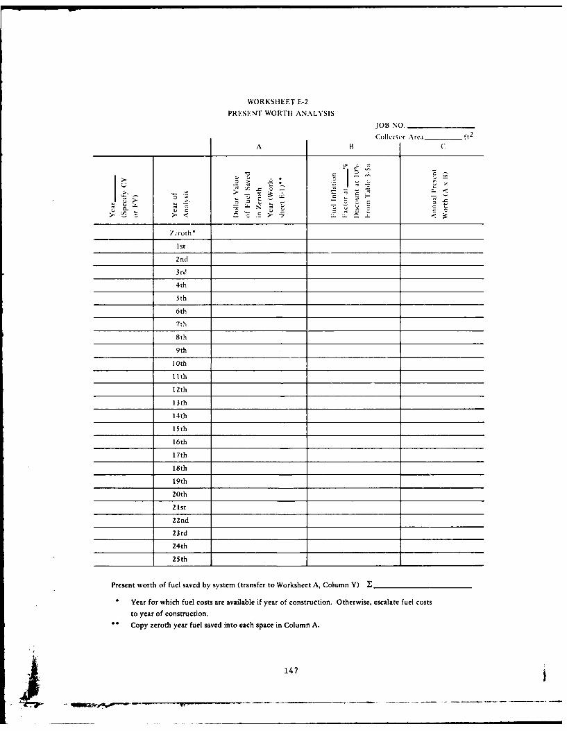
WORKSHEET E-2
PRESENT WORTH ANALYSIS
JOB NO.
Collcctor Area ft 2
A B (
A C
- --0d
CL
> 0 > -E>-
7troth
1st
2nd
3 rJ
4th
5th
6th
7th
8th
9th
I 0th
IIth
12th
13th
14th
15th
16th
17th
18th
19th
20th
21st
22nd
23rd
24th
25th
Present worth of fuel saved by system (transfer to Worksheet A, Column Y) __
Year for which fuel costs are available if year of construction. Otherwise, escalate fuel costs
to year of construction.
Copy zeroth year fuel saved into each space in Column A.
147
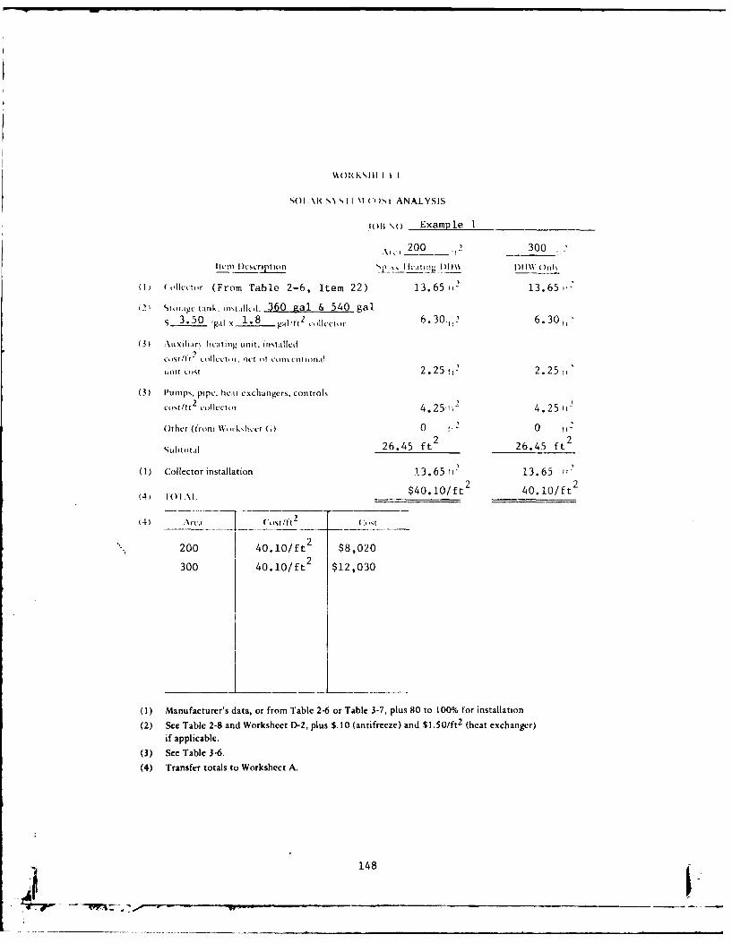
WNl(KSlIl I I I
SO I AR SN\ ~I I \l (i WI ANALYSIS
jol \O) Examp le 1
200 .12 300 2
litum Icscription 0 ctn11 MI0 1\\ ( t)11\
(1) (,oilcktm (From Table 2-6, Item 22) 13.65 13.6
(2 twragu- tank. nq.jlc. 360 gal & 540 gal$3.50 Fg1l x 1.8 gal /tt2 (,,llct,,r 6.30,11 6. 30,2
(3) Auxiliar\ licating unit. insiallcil
kIS1 0111tCOllcttr. nc!t m cenilonal
tLt1 Cist 2 .25 t,2 2. 2 5
(3) Pumips. pipe. hit exchangers, controls
cost/tt2 collvctir 4.251n 4. 25 1,
Othcr (fronm W, -i k.Iv (1) 0 12 2
Subtotal 26.45 ft 2 26.45 ft 2
(1) Collector installation 13. 65 tf13.65
(4) IOl.\ $40. 10/ft 2 40.10/ ft 2
(4) IT11(:i,t/tt2
200 40.10/ft 2 $8,020
300 40.10/ft 2 $12,030
(1) Manufacturer's data, or from Table 2-6 or Table 3-7, plus 80 to 100% for installation
(2) See Table 2-8 and Worksheet D-2, plus $10 (antifreeze) and $1.50/ft 2 (heat exchanger)if applicable.
(3) See Table 3-6.
(4) Transfer totals to Worksheet A.
- - 148
5.0 DIRECTORY OF SOLAR EQUIPMENT MANUFACTURERS
5. 1 Manufacturers Directories
SOLAR ENERGY SOURCEBOOK ... C. W. Martz (ed); Solar Energy
Institute of America, Box 9352, Washington, DC 20005, 1977, 712pp, $12.00 (free to members).
Organized compilation of solar energy related products and ser-
vices in the form of a loose leaf binder; continual updates pro-
vided to members.
SOLAR INDUSTRY INDEX ... Solar Energy Industries Association,
1001 Connecticut Ave. , N.W. , Washington, DC 20036, 1977, 381
pp, $8. 00.
Comprehensive guide to manufacturers and service organizations;
updated annually.
SOLAR PRODUCTS SPECIFICATION GUIDE ... Solar Age Magazine,
Church Hill, Harrisville, NH 03450
A comprehensive list of manufacturers and services for solar
components. Published annually and updated six times per year
by subscription.
5.2 Manufacturers of Flat Plate Collectors and Other Solar Hot Water
Equipment
The following lists are provided for information only. The Civil
Engineering Laboratory does not endorse or recommend the quality or
capability of any individual company. There probably are other com-
panies in any particular area. Local telephone directories can be
checked. The National Solar Heating and Cooling Information Center
often can provide names of companies. Their number is (800) 523-2929,
toll free.
149
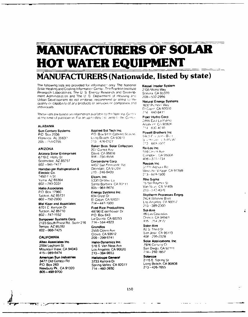
MANUFACTURERS OF SOLARHOT WATER EQUIPMENTMANUFACTURERS (Nationwide, listed by state)The following lists are provided for nformatio- only The National Kessel Insolar SystemSolar Heating and Cooling Information Center. The Franklin Institute 2135 Mono WayResearch Laboratories. The U S Energy Research and DeveoiD- Sonora CA 95370ment Administration and The U S Department of Housing and 209-532-2996Urban Development do not endorse, recommend or attest to h N equality or capability of ary products or services or companies ad Naua Ener Syindiwduals 1632 Pio:nee-r Way
F Calon CA 92020
Thesp iists are based on informaton avalabi to the Natina, Ce.-- 714 4406411
at the time of publicatiorn For an up-l,-date ist write t( no C-.n-tt Piper Hydro Corp.2895 Eat La PIm.n
ALABAMA An inooi CA 92806714 6:30-40C40
Sun Century Systems Applied Sol Tech Inc.PO Box 2036 PO Box 9111 Cabrillo S-t-in P B n.
Florence AL 35630 Lonq Beach CA 90810 5 - ;,.
205-- 754-0795 213 - 426-0127 -'3 -869 2320Baker Bros. Solar Collectors
ARIZONA 201Ra-Los Inc.
Arizona Solar Enterprises Davis CA 95616 559 U A0n Av 8
6719 E Holly St 916--756-4558 40n-CA 9508
Scottsdale AZ 85257 Conserdyne Corp.
602-945-7477 4437 San Fernando Rd Raypak inc.
Hansberger Refrigeration & Glendale. CA 9 l204 31111 Agauri Rd
Electric Co. 213 -246-8409 2estiikV,1ace CA 91359
2450 Pn St Elcam. Inc.
Yuma, AZ 85364 5330 Debhie La Rho Sigma602 - 783-3331 Santa Barbara CA 93111 15150 Raymer St
Helio Associates 805-964-8676 Van N i/'-. CA 91405
PO Box 17960 Energy Systems Inc. 213- ') 12-4376
Tucson. AZ 85731 634 Crest Dr Skytherm Processes Engrg.602 -792-2800 El Cajon CA 92021 2424 ',lshire Blvdt
Mel Kiser and Associates 714-447-1000 Los Angpels CA 9001 7
6701 E Kenyon Dr Fred Rice Productions 213 -389-230
Tucson, AZ 85710 48780 Eisenhower Dr Sol-Aire602- 747-1552 P 0 Box 643 46 Las Cascadas
Sunpower Systems Corp. La Quinta CA 92253 OrinrM CA 94563
2123 South Priest Rd ,Suite 216 714-564-4823 415 2)4 2172
Tempe, AZ 85282 Grundfos Solar-Aire602-968-7425 2555 Clovis Ave 82 S Third St
Clovis, CA 93612 San Jose CA 95113CALIFORNIA 209--299-9741 408-295-2528
Alten Associates Inc. Helio-Dynamics Inc. Solar Applications. Inc.2594 Leghorn St. 518 S Van Ness Ave 7926 Convoy Ct
Mountain View, CA 94043 Los Angeles. CA 90020 San Diego. CA 92111415-969-6474 213-384-9853 714- 292-1857
American Sun Industries Heliotrope General Solarcoa3477 Old Conejo Rd 3733 Kenora Dr 2115 E Spring StPO Box 263 Spring Valley. CA 92077 Long Beach. CA 90808Newbury Pk, CA 91320 714-460-3930 213 -426-7655805-498-9700
150
"i "": - - V r-. ---.. . . .. ... . .. .. .
Solar Energy Digest Sunwater Energy Products Solaron Corp.PO Box 17776 i'488 P-ur'etr VNav :::7 300 Gallerina TowerSan i~oCA 92117 El Caumr CA 92020 720 S Colorado Blvd714 -277-2980 7 14 -442-1532 Denver. 00 80222
Solar Energy Systems Iic. Unit Span Architectural Systems 303- 759-0101336 East Car-on St )9119 Ma isot) AveCON TIUCajron, CA 9i0049 Ct'iOCA 91311CON TCT213 -549-4012 13 - 998-1131 Falbel Energy Systems Corp.
Solar 11 Enterprises Western Energy Inc. P0 Box 621416 Buai C'e,,k R,: 154 Furei;: Avi Greenwich CT 06830
Ls0 6Ci*,O CA 9503C0 Pi- Ato, CA 9430? 203-357-0626a.r 354 3353, 415b - 3 --.- 3 7 ! Hubbell
SlreisInc. Ying Manufacturing Corp 45 Seymour StSol1r4:nlc Stratford. CT 06497
-''~)A 9123 CAA.' 203-- 378-2659
-16 kA06 .'. 'K-8399 International EnvironmentalSolair Master Solar Panels Energy Inc.
COLORADO 275 Windsor St
, - 934 ,4 Design Works HrfrC 62217U B 71 - 203 -249-5011
Solar Uitilities Co ..''.r; CO 81435 Solar Heating Systems Corp.-- ' <rEnergy Dynamics Corp 151 John Downey Df
V ', rJ. ",(- ', VA i' V i :'p Rd New Britain. CT 06051
Solarway . at Swn'' .s CO 80902 2G3--224-2164
* 27 3o'1 4.--033?1 Solar tndustries Inc.1I CA 95470) Enertech Corp. 100 Captain Nevilie Dr
~ 96 ~LI 4 P0 ox CX09 Waterbury. CT 06705
Solergy Inc 'IMCO0 80401 203-753-11952 03- 64-'-3891 Spiral Tubing Corp.
CA~~ 94 11 Entropy Limited 544 John Downey Dr
.I 4 5i-.43() PO Bo 2206 New Britain. CT 06051
Suinburst Solar Energy Inc. B>,i-r. C0,903063 203-244-2409( :: ,.79303- 443-3319 Sunworks
I irk tA 94025Future Systems Inc.P0Bx14411, 3' 7802? '25t00 VV C( clat Dr New Haven CT 06508
The SundLu CO LaiKewo(yi CO 80228 203-934-6301
33 13 K, f La 303 -989-0431 Wilson Solar Kinetics Corp.A rr -. in a -A 9L2804 Miromit/American Heliothermat Corp. P0 Box 17308
714 28-8'3351 S amarc D Sute 60 est Hartford, CT 06117
Sunshine Utitity Co. Denver CO 80237 232346144.4 Prron,i(r Way S'..r'-, 9 & IL, 303 - 773-6085 DELAWAREEl Calon CA 92020 R. M Products DuPont Co.714. 4410-3151 50 10 Cook St Nemnours Bldg .'Rm 2475!
Sunsource Inc. Derv"i.r 0080216 Wilmington. DE 198981291 S' Brass Lant'-1 Di 303 --825-0203 302-999-3456La K i r CA 90631 Solar Energy Research Corp. SlrSsesIc213 943-8883 1228 15th St S2 olartSystm C.D
Di~nf-fCO 8202Rehoboth Beach. DE 19971303-- 57 -5 9 302-227-2323
U 151
LI__ __
7-7- ~ **-~--
MANUFACTURERSDISTRICT OF COLUMBIA Chemical Processors Inc. J & R Simmons Construction Co.Business and Technology, Inc. PO Box 10636 2185 Sher. ,;d Dr2800 Upton St . N W St Petersburg. FL 33733 South Dayloni FL 32019Washington. DC 20008 813-822-3689 904 -- 677-5832202-362-5591 or Consumer Energy Corp. Largo Solar Systems Inc.202-244-4902 4234 S W 75th Ave 2525 Key La'qo La
McCombs Solar Co. Miami FL 33155 Mail Only1629 K St, NW Suite 520 305-266-0124 Fort Lat( - ', !ile FL 3331,Washington. DC 20006 CSI Solar Systems Div. 305-583-8090202 - 296-1540 12400 49th St. Matthews Systems IncNatural Energy Corp. Clearwater. FL 33520 P0 Box 16661001 Connecticut Ave N W 813-577-4228 Gafnesvflie. FL. 32602Washington, DC 20036 D & J Sheet Metal Corp. 904-376-5222202-296-7070 10055 N W. 7th Ave National Solar SystemsSolartherm Miami, FL 33150 PO Box 173481640 Kalmia Rd. N.W 305-757-7033 Tampa FL 33682Washington. DC 20012 Del Sol Control Corp. 813--933-43P?202-882-4000 11914 U S Highway No I OEM Products Inc./Thomason Solar Homes Inc. Juno FL 33408 Solarmatic Div.609 Cedar Rd S E :05 --626-6116 2413 Gardon StWashington DC 20022 Energy Applications Inc Tampa FL 33605301-336-4042 840 Margie Dr 813 --247-5858
Titusville. FL 32780 SemcoFLORIDA 305-269-4893 1091 S W 1: Wa,
American Solar Power. Inc. Falkner Inc. Deerfield Bt ach FL 33441715 Swann Ave. 6121 Alden Rd ,,PO Box o,3 305-427-0040Tampa, FL 33606 Orlando, FL Solar Comfort Inc.813-251-6946 305-898-2541 249 S Grove StAstro Solar Corp. Flagala Corp. Venice, FL 33595744 Barnett Dr./Unit No 6 9700 W Highway 98 813-485-0544Lake Worth, FL 33461 Panama City, FL 32401 Solar Controlar Inc.305-965-0606 904-234-6559 P 0 Box 8703Aztec Solar Co. Florida Solar Power Inc. Orlando. FL 32806PO Box 272 PO. Box 5846 Solar Development Inc.Maitland. FL 32751 Tallahassee. FL 32301 4180 West Roads Dr305-628-5004 904-244-8270 West Palm Beach FL 33407Beutels Solar Heating Co. General Energy Devices 305-842-89357161 Northwest 74th St 1743 Ensley Ave Solar Dynamics Inc.Miami, FL 33166 Clearwater, FL 33516 PO Box 3457305-885-0122 813-586-1146 Hialeah, FL 33013D. W. Browning Contracting Co. Gulf Thermal Corp. 305--921-7911475 Carswell Ave PO Box 13124 Airgate Branch Solar Electric InternationalHolly Hill, FL 32017 Sarasota. FL 33580 6123 Anno Ave904-252-1528 813-355-9783 Orlando, FL 32809Capital Solar Heating Inc. Hill Bros. Inc./Thermal Div. Solar Energy Components Inc.376 N W 25th St 3501 N W 60th St 1605 North Cocoa BlvdMiami, FL 33127 Miami. FL 33142 Cocoa. FL 32922305-576-2380 305-693-5800 305-632-2880
152
MANUFACTURERSSolar Energy Products Inc. Southern Lighting/ Scientific-Atlanta Inc.1208 N W 8th At. Universal 100 Products 3845 Pteasantdale RdGainesville. Fl -0+301 501 Elwell Ave Atlanta GA 30340904 - 377-652e' Orlando. FL 32803 404 -449-2000Solar Energy Resources Corp. 305-894-8851 Solar Technology Inc.10639 S A 18t Torr Sun Power 3927 Oakclif Industrial CtMtamri FL 33157 10400 S W 187th St Atlanta. GA 30343305 -233-0 ,711 Miami. FL 33157 404-449-0900Solar Energy Systems 305-233-2224 Southeastern Solar Systems1243 South Florida Ave Sunseeker Systems Inc. PO Box 44066Rockledqe. Fl 32955 100 W Kennedy Blvd Atlanta. GA 30336305 -632-6251 Tampa. FL 33602 404-691-1864Solar-Eye Products, Inc. 813-223-1787 Wallace Company1300 N W McNabe Rd Systems Technology Inc. 831 Dorsey StBI 4i GNH P 0 Box 337 Gainsville. GA 30501Ft Lauderdale FL 33307 Shalimar, FL 32579 404-534-5971305 974-2500 904-863-9213Solar Fin Systems Unit Electric Control Inc./ HAWAII140 S Dixie Hwy Sol-Ray Div. The Solaray Corp.St Auqustine FL 130 Atlantic Dr 2414 Makiki Heights Dr904--824-3522 Maitland, FL 32751 Honolulu. HI 96822Solar Heating & 305-831-1900 808-533-6464Air Conditioning Systems Universal Solar Energy Co.13584 49th St North 1802 Madrid Ave. ILLINOISGlearwater FL 33520 Lake Worth, FL 33461 Amcon Inc.813--577-396j1 305-586-6020 211 W Willow St.Solar Industries of Florida Wilcon Corp. Carbondale, I L 62901P 0 Box 9013 3310 S.W. Seventh 618-457-3022Jacksonville. FL 32208 Ocala, FL 32670 A.O. Smith Corp.904 -768-4323 904-732-2550 P 0 Box 28Kankakee, IL 60901Solar Innovations Wilcox Manufacturing Corp. 815-933-8241412 Longfellow Blvd PO. Box 455Lakeland FL 33801 Pinellas Park. FL 33565 Chamberlain Manufacturing813-688-8373 813-531-7741 Corp.Solar Products Inc./Sun-Tank W. R. Robbins & Sons 845 Larch Ave.614 N W 62nd St 1401 N.W 20th St Elmhurst. IL 60126Miami, FL 33150 Miami, FL 33142 312-279-3600305--756-7609 305-325-0880 ITT Fluid Handling Div.Solar Systems by Sundance Corp. Youngblood Company, Inc. 4711 Golf Rd.
4815 S W 75th Ave 1085 NW 36th St. Skokie, IL 60076
Miami. FL 33101 Miami, FL 33127 312-677-4030
305-264-1894 305 -635-2501 Johnson Controls Inc./Penn Div.2221 Camden Ct.
Solar Water Heaters o New GEORGIA Oak Brook. II 60521Port Richey
540 Palmetto Independent Living Inc. 312-654-4900New Port Richey FL 33552 5715 Buford Hwy., N E. Olin Brass Corp./Roll-Bond Div.813-848-2343 Doraville. GA 30340 E Atton, IL 62024
404-455-0927 618-258-2000
153 j
47" .
MAN UFACTU RERSPak-Tronics Inc. Daystar Corp MINNESOTA4044 N Rockvieli Ave 90 Can -biN.q A To Z Solar ProouctsChicago. IL 60618 BurliinqIn A Y. * E .6'l S'312 --478-8585 617 ?72.846Co w ASolar Dynamics Corp. Diy-SoI Inc. n 7 -'
550 Frontage Rd P 0 B x 6 14 Holtman Products. InCNorthfield IL 60093 MailbS MA l1A1. 7-
312- 446-5242 Kennecott Copper Corp .
Sun Systems Inc. :iiS > -ti; S!P0 Box 155 Ltx no,: n MA01 "I Honeywell IncEureka. IL 61530 617 862-S. 6F o ,i309-685-9728 Sunkeeper M"*: M
PO Box 34 t' . - .2KINDIANA Shavshf~en V ill,; -, uIse EngineeringSolar Energytics. Inc. Antiovor MA 018- A,*hP0 Box 53", 617 --470-0551- . V
Jasper IN 47546 Sunsav Inc. I 8812- 482-1416 9 mill St SheldahltAdvanced
Lawrenco MA 04Products Div.IOWA 617 - 686-8040 - 4. M 5-Lennox Industries Inc. Sun Systems Inc.200 S 12th Ave PO Box 347 Solargizer Corp.Marshalltown IA 50158 Mlon MA o 186 ~ 'O -,414- 754-4011 617 -268-8178 1vxt MN5~8Pleiad Industries, Inc. Vaughn Corp./Solargy Systems .1.3 .-5734RR 1 P0 Box 57 386 Elm StWest Branch IA 52358 Salisbury, MAO 01950 NEVADA319-643-5650 617-462-6683 Richdel Inc.Solar AirePODaeAP0 Box 276 MICHIGAN ran AV97North Liberty, IA 52317 Dow Chemical, USA 702 -882-6786319-626-2343 2020 Dow Center S_ W. Ener-Tech Inc.KENTUCKY Midland. MI 48640 3030 S Valley View& B,,,
MdWsenSlrSses 517-636-3993 Las Vegas NV 89102M2Iervn ola r Sses Solarator Inc. 702 - 873-1975P0O. Box 2384 16231 W 14 MileRdPaducah. KY 42001 Birmingham. MI 48009 NEW HAMPSHIRE502-443-6295 313-642-9377 Helioipticon Corp.
Solar Research PO Drawer 330MARYLAND 525 N Fifth St Plymoutlh NH 03264KTA Corp. Brighton. Ml 48116 603-536-107012300 Washington Ave. 313-227-1151 Kalwall Corp./Rockville, MD 20852 Solartran Co. Solar Components Div.201-568-2066 Escanaba, Ml 49829 PO Box 237
906-786-4550 Manchester, NH 03105MASSACHUSETTS Tranter 603-668-8186Columbia Solar Energy Div. 735 East Hazel St55 High St Lansing, Ml 48909Holbrook, MA 02343 517-372-8410617-767-0513
154

MANUFACTURERSNEW JERSEY Hitachi American Ltd. Owens Illinois Inc.Berry Solar Products 437 Madison Ave P O Box 1035,, Ibidqe At Mair' Nw York NY 10022 Toledo OH 43666PO Bo 327 ' 838-4804 419-242-6543Fisin NJ0881t International Environment Corp. Ranco Inc.201 549-3800 129 Halstead Ave 601 W Fifth AveCalmac Manufacturing Corp Mamaroneck NY 10'43 Columbus OH 43201P0 Bo 710E 914-698-8130 614 -294-3511Er r} .v,,'ood NJ 07631 Revere Copper & Brass Inc. Solar Energy Products Co.,101 569-0420 PO Box 151 12f Miller RdHeilemann Electric Rome NY 13440 Avon Lake OH 440122 7 Mountain View Rd 315-338-2401 216-933-5000\Vrrt n_ NJ 07060 Solar Energy Systems, Inc. Solar Heat Corp.20 757-4507 P 0 Box 625 Sentry P1 1252 French AveSolar Energy Systems Inc. Scarsdale. NY 10583 Lakewood OH 44107One Olney Ave 914- 725-5570 216-228-2993Cherry Hill NJ 08003 Sol-Therm Corp. Solar Home Systems Inc.609 424-4446 7 West 14th St 12931 West Geauga TrailSSP Associates New York. NY 10011 Chesterland. OH 44026704 BILLe Hill Rd 212 -691-4632 216- 729-9350Ri, er Vale NJ 0,675 Solar Vak Inc.201 -391-4724 NORTH CAROLINA PO Box 1444
Carolina Solar Equipment Co. Dayton. OH 45414NEW MEXICO PO Box 2068 513-278-6551K-Line Corp. Salisbury, NC 28144911 Pennsylvania Av, 704 - 637-1243 OKLAHOMAAmuoni.quf, NM 87110 Standard Electric Co. Brown Manufacturing Co.505 268-3379 P0 Box 631 PO Box 14546Sigma Energy Products Rocky Mount NC 27801 Oklahoma City OK 731141.05B San Mateo N E 919-442-1155 405--751-1343Albuquerque NM 87110 Tri-State Solar King. Inc.505-262-0516 OHIO PO Box 503
Glass-Lined Water Heater Co. Adams, OK 73901NEW13000 Athens Ave 405 - 253-6562Advance Cooler Cleveland. OH 44107Manufacturing Corp. 216-521-1377 OREGONRoute 146 Howard Bell Enterprises Inc. Scientifico Components Co.Bradford Industrial Park PO Box 413 35985 Row River RdCifton Park. NY 12065 Valley City, OH 44280 Cottage Grove, OR 97424518-371-2140 216-483-3249Ford Products Corp. Libbey Owens Ford/ PENNSYLVANIAFord Products Rd Lbe wn odVale Crotute Y 1Technical Center Aluminum Co. of AmericaValley Cottage, NY 10989 1701 East Broadway Alcoa Bldg914 -358-8282 Toledo. OH 43605 Pittsburgh. PA 15219Grumman Corp./ 419-247-4355 412-553-2321Energy Sys. Div. Mor-Flo Industries Inc. Ametek Inc./Dept GR 18450 South Miles Rd Power Systems Group4175 Veterans Memorial Hwy Cleveland, OH 44128 1 Spring AveRonkonkoma NY 11779 216-663-7300 Hatfield PA 19440516-575-706215-822-2971
155
MANUFACTURERSEnviropane Inc. Energy Converters Inc. VIRGINIA348 N Marshall St 2501 N Orchard Knob Ave Atlantic Solar Products Inc.Lancaster, PA 17602 Chattanooga TN 37406 Reston international Center717-299-3737 615--624-2608 Sute 227General Electric Co Oak Ridge Solar 11800 Sunrise Valley DrPO Box 8661, Bldg 7 Engineering Inc. Reston, VA 22091Philadelphia, PA 19101 P0 Box 3016 703-620-2300215-962-2112 Oak Ridge TN 37830 Helios Corp.Heliotherm Inc. 615-482-5290 1313 Belleview AveLenni, PA 19052 State Industries Inc. Charlottesville, VA 22901215-459-9030 Cumberland St 804 -293-9574Packless Industries Inc. Ashland City TN 37015 Reynolds Metals Co.PO Box 310 615-792-4371 P0 Box 27003Mount Wolf. PA 17347 W.L. Jackson Manufacturing Co. Richmond. VA 23261717-266-5673 PO Box 11168 804-2,1-3026PPG Industries Chattanooga, TN 37401 Solar AmericanOne Gateway Center 615-867-4700 106 Sherwood DrPittsburgh. PA 15222 Williamsburg VA412-434-3555 TEXAS 804 -- 229-0657Practical Solar Heating American Solar King Corp. Solar Corp. of America/209 S. Delaware Dr Rt 611 6801 New McGregor Hwy Intertechnology Corp.Easton. PA 18042 Vaco TX 76710 100 Main St215-252-6381 817- 776-3860 Warrentcn VA 22186Simons Solar En,-ironmental Cole Solar Systems Inc. 703-347-7900Systems Inc. 440A E St Elmo Rd Solar Energy Co.24 Carlisle Pike Austin, TX 78745 P0 Be, 649Mechanicsburg, PA 17055 512--444-2565 Gloucester Point VA 230f2717-697-2778 Northrup Inc. Solar One Ltd.
Solar Heat Co. 302 Nichols Dr 709 Brdneck RdPO Box 110 Hutchins. TX 75141 V0gr9i Beach VA23451
Greenville PA 16125 214-225-4291 804 -422-3262412-588-5650 Solar Systems Inc. Solar Sensor SystemSolar Shelter 507 W Elm St 4220 Berritt StPO Box 36 Tyler. TX 757' 1 Farfax VA 22030Reading. PA 19603 214-592-5343 703- 273-2683215-488-7624 Soltex Corp.Sun Earth Solar Products Corp. P 0 Box 55703 WASHINGTONRD 1/PO Box 337 Houston, TX 77055 WASHINGToNGreen Lane, PA 18054 713-780-1733 747 16th Street. E215-699-7892 Solus, Inc. Seattle. WA 98112Sunwall Inc. PO Box 35227 206 -322-3753P.O. Box 9723 Houston TX 77035Pittsburgh. PA 15229 713-772-6416 E&K Service Co.412-364-5349 1847t v
VERMONT Bothell. WA 98011
RHODE ISLAND Sol-R-Tech 206-486-6660
Solar Homes Inc. PO Box G WISCONSIN2 Narragansett Ave Hartford VT 05047Jamestown, RI 02835 802-295-9342 Solaray Inc.401-423-025324 S Kidd St401-423-1025 Whitewater, WI 53190
TENNESSEE 414-473-2525ASG Industries Sun StoneP. Box 929 PO Box 941Kingsport, TN 37662 Sheboygan. WI 53081
615-245-0211 414 --452-8194
156
6.0 REFERENCES (0) AND SELECT BIBLIOGRAPHY
AIA Research Corp. (1979). A survey of passive solar buildings. San
Mateo, Calif., Soiar Energy Information Services, 1979.
American Society of Heating, Refrigerating, and Air-Conditioning
Engineers (1979). ASHRAE handbook of fundamentals, chapter 22.
New York, N.Y., American Society of Heating, Refrigerating, and
Air-Conditioning Engineers, 1979.
" Anderson, B. (1976). Solar home book. Harrisville, N.H., Cheshire
Books, 1976.
Anderson, L. B., Hottel, H. C., and Whillier, A. (1955). Solar
energy research no. 47, Madison, Wis. , University of Wisconsin, 1955.
" Anderson, M. (1979). "Accolade at Honeywell Plaza," Solar Age, vol 4.
no. 6, Jun 1979, pp 32-36.
Andrews, J. W. and Wilhelm, W. (1977). Low cost site assembled solar
collector designs for use with heat pumps. Brookhaven National Labora-
tory, Report no. BNL 50671, Upton, N.Y., May 1977.
Antolini, H. L., et al. (1978). Sunset homeowner's guide to solar
heating. Menlo Park, Calif., Lane Publishing Co., 1978.
" Bainbridge, D. A. (1978). "Natural cooling in California," in Proceed-
ings, 1978 Annual Meeting of the American Section, International Solar
Energy Society, Denver, Colo., Aug 28-31, 1978. Newark, Del.,
International Solar Energy Society, 1978, vol 2.1, pp 475-487.
Balcomb, D., et al. (1975). Solar heating handbook for Los Alamos.
Los Alamos Scientific Laboratory, Report no. LA-5967, Los Alamos,
N.M., May 1975.
157
* Balcomb, J. D. (undated). "Rules of thumb for passive solar he;iling
in New Mexico," New Mexico Solar Energy Association Bulletin, vol 2.
nos. 5, 6, and 7, by J. Douglas Balcomb of Los Alamos Scientific Labo-
ratories.
Balcomb, J. D., Hedstrom, .1. C., and Rogers, B. T. (1975). "Design
considerations of air cooled collector/rock-bin storage solar heating
systems," in international Solar Energy Conference and Exposition. Los
Angeles, Calif., Jul 28-Aug 1, 1975. Rockville, Md., International
Solar Energy Society, 1975, pp 314-315.
* Barber, R. E. (1975). "Design and test of a prototype 3-ton solar
heated Rankine cycle air conditioner," in 1975 International Solar
Energy Congress and Exposition, Los Angeles, Calif., Jul 28-Aug 1,
1975. Rockville, Md. , International Solar Energy Society, 1975,
pp 405-406.
* Barnaby, C. W., et al. (1977). Solar for your present home, prepared
for the California Energy Commission, Berkeley, Calif., Berkeley Solar
Group, 1977.
Beard, J. T. et al. (1976). "Performance and analysis of 'Solaris'
water-trickle solar collector," in Sharing the Sun: Solar Technology in
the Seventies, Joint Conference of the International Solar Energy
Society, American Section and Solar Energy Society of Canada, Inc.,
Winnipeg, Manitoba, Aug 15-20, 1976. Cape Canaveral, Fla., Interna-
tional Solar Energy Society, American Section, 1976, vol 2, pp 46-63.
* Beck, E. J. and Field, R. L. (1977). Solar heating of buildings and
domestic hot water. Civil Engineering Laboratory, Report R-835, Port
Hueneme, Calif., Nov 1977. (ADA054601)
$ Beckman, W. A. (1977). "Problems of solar cooling systems,"
Sunworld, no. 6, Nov 1977, pp 2-6.
158
-A,
* Beckman, W. A., Klein, S. A., and Duffie, J. A. (1977). Solar heat-
ing design by the F-chart method, New York, Wiley-Interscience, 1977.
Braden, S. (1977). Graphic standards of solar energy. Boston,
Mass., CBI Publishing Co., 1977.
Cole-Appel, B. E. and Haberstroh, R. D. (1976). "Performance of
air-cooled flat plate collectors," in Sharing the Sun: Solar Technology
in the Seventies, vol 3, pp 116-117.
* Cole, R. L., et al. (1979). Design and installation manual for thermal
energy storage. Argonne National Laboratory, Report no. ANL-79-15,
Argonne, 111., Feb 1979.
Consroe, T., et al. (1974). Alternate strategies for optimizing energy
supply, distribution, and consumption systems on Naval bases, vol 2.
Advanced energy conservation strategies. Civil Engineering Labora-
tory, Contract Report CR 74.007, Port Hueneme, Calif., Jan 1974.
(AD786757, vol 1 published as CEL CR 74.006, Nov 1973, AD777471).
De Winter, F., (1973). Fin effectiveness or efficiency in flat plate
solar collectors. New York, N.Y., Copper Development Association,
1973.
* Duffie, J. A. and Beckman, W. A. (1974). Solar energy thermal
processes. New York, Wiley-Interscience, 1974.
Duffie, J. A., Beckman, W. A., and Dekken, J. G. (1977). "Solar
heating in North America," Mechanical Engineering, vol 99, no. 11, Nov
1977.
Duffie, J. A., Chung, R., and Lof, G. 0. G. (1963). "A study of a
solar air conditioner," Mechanical Engineering, vol 85, no. 8, Aug 1963,
pp 31-35.
159
*Durlak, E. R. (1979a). Analysis of solar collectors, type: double
glazed glass cover with aluminum absorber plate, copper waterways, flat
black coating. Civil Engineering Laboratory, Technical Memorandum
M63-79-16, Port Hueneme, Calif. , Jul 1979.
*Durlak, E. R. (1979b). Computer programs that simulate solar system
performance. Civil Engineering Laboratory, Tech data Sheet 79-06, Port
Hueneme, Calif., Apr 1979.
Edwards, D. K. (1977). Solar collector design. Philadelphia, Pa..
Franklin Institute Press, 1977.
Edwards, D. K., et al. (1960). Basic studies on the use and control
of solar energy. Los Angeles, Calif. , University of California.
Engineering Report no. UCLA 60-93, Oct 1960.
Energy Research and Development Administration (1975). Catalog on
solar energy heating and cooling products. Washington, D .C., Oct
1975.
Energy Research and Development Administration (1976). An economic
analysis of solar water and space heating. DSE-2322-1, Washington,
D.C., Nov 1976.
Energy Research and Development Administration (1977). ERDA facili-
ties solar design handbook. Prepared by Los Alamos Scientific Labora-
tory, Group WX-4, Washington, D.C., Aug 1977.
Energy Research and Development Administration, San Francisco Opera-
tions Office (1976). Pacific regional solar heating handbook, 2nd ed.
Washington, D.C., GPO, Nov 1976.
*Eyre, P. E. (1978). Corrosion in solar systems. Report done on CEL
contract nos. N62583/77 MR 861 and N62583/77 MR 881. Port Hueneme,
Calif., Dec 1978.
160
Federal Energy Administration (1976). Buying solar. Report no.
FEA/G-76/154, Washington, D.C., Jun 1976. (PB 262134)
Florida Solar Energy Center (1979). Summary test results FSEC certi-
fied solar collectors. Cape Canaveral, Fla., Feb 1979.
Foster, W. M. (1977). "Design options for residential solar hot water
heating systems," Solar Engineering, Oct 1977, pp 30-32.
Garg, H. P. (1974). "Effect of dirt on transparent covers in flat plate
solar energy collectors," Solar Energy, vol 15, no. 4, Apr 1974,
pp 299-302.
Gupta, G. L. and Garg, H. P. (1968). "System design in solar water
heaters with natural circulation," Solar Energy, vol 12, 1968, pp 163-
182.
Hill, J. E. and Kusada, T. (1974). Method of testing for rating solar
collectors based on thermal performance. National Bureau of Standards,
Report no. NBSIR 74-635, Washington, D.C., 1974.
Hottel, H. C., and Woertz, B. B. (1942). "The performance of flat-
plate collectors," American Society of Mechanical Engineers, Transac-
tions, vol 64, no. 2, Solar-Heat, Feb 1942, pp 91-104.
Joncich, D., et al. (1978). Design of solar heating and cooling sys-
tems. Champaign, Ill., Construction Engineering Research Laboratory,
Technical Report E-139. Oct 1978.
Kimbell, B. W. (1978). Recommendation of preferred solar heating
system combinations. Report done on CEL contract nos. N62583/77
MR 861 and N62583/77 MR 881. Port Hueneme, Calif., Dec 1978.
Kirts, R. E. (1978). Technical and economic evaluation of four solar
assisted heat pump systems. Civil Engineering Laboratory, Technical
Memorandum M63-78-6, Port Hueneme, Calif., Aug 1978.
161
-----__ _ _ _ __ _ _ _ _ __ _ _ _ __ _ ___ _ _ _ _
" Klein, S. A., Beckman, W. A., and Duffie, J. A. (1976). "A design
procedure for solir heating systems," Solar Energy, vol 18, no. 2.
1976, pp 113-127.
" Klein, S. A., Beckman, W. A., and Duffie, J. A. (1977). "A design
procedure for solar air heating systems," Solar Energy, vol 19. no. 5,
1977, pp 509-512.
* Kohler, J. (1978). "Rules of thumb for sizing storage," Solar Age, vol
3, no. 4, 1978.
Kreider, J. J. and Kreith, F. (1975). Solar heating and cooling:
engineering, practical design, and economics. New York, McGraw-Hill,
1975.
Liu, B. H. Y. and Jordan, R. C. (1963). "A rational procedure for
predicting the long-term average performance of flat-plate solar energy
collectors," Solar Energy, vol 7, no. 2, Apr-Jun 1963, pp 53-74.
* Lof, G. 0. G. (1977). "Systems for space heating with solar energy,"
in Applications of Solar Energy for Heating and Cooling of Buildings,
ed. by R. C. Jordan and B. Y. H. Liu. New York, American Society
of Heating, Refrigerating, and Air-Conditioning Engineers, 1977, XII,
19 pp.
Lof, G. 0. G. and Nevens, T. D. (1953). "Heating of air by solar
energy," Ohio Journal of Science, vol 53, 1953, pp 272-280.
Lof, G. 0. G. and Tybout, R. A. (1973). "Cost of house heating with
solar energy," Solar Energy, vol 14, no. 3, Feb 1973, pp 253-255.
Lof, G. 0. G., Karaki, S., and Smith, C. C. (1976). "Comparative
performance of solar heating with air and liquid systems," in Sharing
the Sun: Solar Technology in the Seventies, vol 3, pp 106-117.
j 162A
" Mazria, E. (1979). Passive solar energy book. Emmaus, Pa., 1979.
" McCullagh, J. C. (1978). Solar greenhouse book. Emmaus, Pa., 1978.
McGarity, A. E. (1977). Solar heating and cooling: an economic
assessment. Washington, D.C., National Science Foundation, 1977.
0 Merriam, R. (1977). Solar air conditioning study. Civil Engineering
Laboratory, Contract Report CR 77.018, Port Hueneme, Calif., Apr
1977. (ADA043951)
* Montgomery, R. H. (1978). Solar decision book: your guide to making
a sound investment. Midland, Mich., Dow Corning Corp., 1978.
National Aeronautics and Space Administration (1974). Harnessing the
sun's energy for heating and cooling. George C. Marshall Space Flight
Center, Ala., 1974.
* National Solar Heating and Cooling Information Center (1979). Solar hot
water and your home, RockviUe, Md., Aug 1979. (HUD-PDR-466)
Obrecht, M. F. and Myers, J. R. (1973). "Performance and selection
of materials for potable hot water service," Heating, Piping, and Air
Conditioning, vol 45, Aug 1973. (Also in: Materials Protection and
Performance, vol 12, no. 4, Apr 1973, pp 17-24)
Office of Technology Assessment (1978). Application of solar technol-
ogy to today's energy needs. Washington, D.C., Jun 1978. (2 vols)
Pesko, C., ed. (1975). Solar directory. Ann Arbor, Mich., Ann
Arbor Science Publishers, 1975.
163
Pickering, E. E. (1975). "Residential hot water solar energy btorage,"
in Proceedings of the Workshop on Solar Energy Storage Subsystems for
Heating and Cooling of' Buildings, Charlottesville, Va., Apr 16-18,
1975, ed. by L. U. lilleleht. Washington, D.C., National Science
Foundation, 1975.
Rho-Sigma (undated). IBrochurel, 11922 Valerio Street, North
Hollywood, Calif.
Scholten, W. and Curran, H. (1979). "Active cooling update," Solar
Age, vol 4, no. 6, Jun 1979, pp 37-41.
Selcuk, K. (1971). "Thermal and economic analysis of the overlapped
glass plate solar air heater," Solar Energy, vol 13, 1971, pp 165-191.
Sharp, M. K. and Loehrke, R. I. (1978). Stratified thermal storage in
residential solar energy applications. Report done on CEL contract no.
N68305-76-C-0036 and EtDA contract no. EG-72-5-024523.AOO. Port
Hueneme, Calif., Jun 1978.
Solar Age Magazine (1979). Solar products specification guide.
Harrisville, N.H., Solar Vision, Inc., Jul 1979.
Solar Engineering (1978). "The bigger the better for solar in assisting
heat pump systems," Solar Engineering, Feb 1978, pp 36-43.
Solar Engineering (1978). "Solar system chemicals," Solar Engineering,
Aug 1978, p 42.
Swindler, A. (1979). Size and cost guidelines for solar heating and
cooling systems. Report done on CEL contract nos. N62583/77 MR 861
and N62583/77 MR 881. Port Hueneme, Calif., Apr 1979.
Thomason, H. E. and Thomason, H. J. L. (1973). "Solar houses/
heating and cooling progress report," Solar Energy, vol 15, no. 1, May
1973, pp 27-39.
164
Tybout, R. A. and Lot, G. 0. G. (1970). "Solar house heating,"
National Resources Journal, vol 10, 1970, pp 26i8-326.
U .S. Department of Commerce, Economic Development Administration
(1977a). Solar heating and cooling of residential buildings: sizing,
installation, and operation of systems. Prepared by the Solar Energy
Applications Laboratory, Colorado State University, Washington, D .C.,
Oct 1977.
U .S. Department of Commerce, Economic Development Administration
(1977b). Solar heating and cooling of residential buildings: design ofsystems. Prepared by the Solar Energy Applications Laboratory,
Colorado State University, Washington, D .C., Oct 1977.
U .S. Department of Energy (1978a). Solar heating and cooling of
buildings commercialization report, pt. A. Options and strategies.
Washington, D.C., May 1978, 3 vols. (Contract CR-05-70065-0)
U.S. Department of Energy (1978b). Report no. NCP/M2528-01: Legal
barriers to solar heating and cooling of buildings. Washington, D .C.,
Mar 1978.
* U.S. Department of Housing and Urban Development (1977). Report
no. 4930.2: Solar heating and domestic hot water systems, HUD inter-
mediate minimum property standards, Washington, D .C., 1977.
* U .S. National Oceanic and Atmospheric Administration, National Climatic
Center (1968). Climatic atlas of the United States. Asheville, N .C.,
Jun 1968.
*U .S. Naval Facilities Engineering Command (1978). NAVFAC P-89:Engineering weather data. Washington, D .C., Jul 1978.
Veitford, T. E. (1942). Solar water heaters. New York, N.Y.,
Copper and Brass Research Association, Mar 1942.
165
* Werden, l.. C. and Spielvogel, L. G. (1969). "Sizing of service water
healing equipment in commercial and instilutional buildings, pt. 2.
ReseaMrch program data acquisition, reduction and analysis, and recom-
mendations for sizing." ASHRAE Transactions, vol 75, 1969, pp 181-
199.
Whillier, A. (1963). "Plastic covers for solar collectors," Solar Energy,
vol 7, no. 3, Jul-Sep 1963, pp 148-151.
Whillier, A. (1967). "Design factors influencing collector performance,"
in Low Temperature Engineering Applications of Solar Energy, ed., by
R. C. Jordan. New York, American Society of' Heating, Refrigerating,
and Air-Conditioning Engineers, 1967, pp 27-40.
Yellot, J. 1., et al. (1974). "Solar energy utilization for heating and
cooling," in ASHRAE Handbook, vol 3, Applications. New York,
American Society of Heating, Refrigerating, and Air-Conditioning
Engineers, 1974, chap. 59.
Yellot, .J. I., et al. (1975). Solar-oriented architecture. Tempe,
Ariz., Arizona State University, College of Agriculture, 1975.
Zarem, A. M. and Erway, D. D., eds. (1963). Introduction to the
utilization of solar energy. New York, McGraw-Hill, 1963.
166
'I - i
7.0 LIST OF SYMBOLS
A Collector area (ft2 )c
CF Cost of fuel ($/106 Btu)
Cmin Lesser of the heat capacityflow rates in the spaceheating load exchanger
COP Coefficient of performance
C Specific heat of fluidP (Btu/lbmOF)
f Fraction of building loadsupplied by solar heating
fAverage of f over one year
F Function of energy absorbed bycollector/building heating
load (ft-2 )
FL Function of collector heatlosses/building heating load
(ft-2 )
FR Collector heat removal factor( 3.2)
Fj Collector heat exchangerefficiency factor ( 3.2)
G Flow rate through collector
per unit area (lbm/hr ft2 )
I Solar insolation (Langley/day)
IT Average instantaneous solarinsolation on collector
surface
L Gross heat loss rate
(Btu/ft2-degree day)
M Area of building (ft2)
*Mass flow through collector(lbm/hr)
167
.. . ........................ ....... ................... ........
(m C p)c Heat capacity flow ratethrough collector (Btu/hr'F)
(m C p)min The lesser of the two heatcapacity flow rates in thecollector-tank heat exchanger
N Number of days in month
NI Number of days in computationperiod
P Degree days
q c Solar heat collected per ft2
of collector per month(Btu/ft
2mo)
Qd DHW heating load (Btu/day)
Yearly total load (DHW only)Qdt (Btu/yr)
QL Total heat load (space + DHW)per month (Btu/mo)
QLt Yearly total heat loadt (space + DHW) (Btu/yr)
Qu Useful heat collected = Acqc(Btu/mo)
R Gross space heat load =LxMxP
S Slope factor = ratio of directsolar radiation on a tiltedsurface to that on a horizon-tal surface
Ta Average ambient air tempera-
ture (OF)
T. Collector inlet fluid tempera-ture (OF)
To 0Collector outlet fluid temper-ature (OF)
Tref 212*F, a reference temperature
168
.. _ _ _ _ _ _ _ _
UA Overall heat loss coefficientof building times buildingarea (Btu/hr0 F)
UL Collector overall heat losscoefficient (Langleys/OF-day)
V Net space heat load = R x qw
W Weight of DHW to be heated/day
(Ibm)
C Absorptance
e Emittance
c Effectiveness of thec collector-tank heat exchanger
F L Effectiveness of the spaceheating load heat exchanger
q Collector efficiency
ncollect Average collector efficiency
"delivery Delivery efficiency
nw Heater (DHW or space)utilization efficiency
0 Hours of useful sun/day
(Ta) Product of cover transmittanceand plate absorptance account-
ing for dirt and shading
(Ta) Average value of (Ta) overone day
(ta)n (1a) at normal radiationincidence
Utilizability ( 3.12)
169
DISTRIBUTION [IST
AF FO I ,) F 1 .1 N %\Mu .Iiioi. D)(AFB1 (Rl)\ \SFI
5S R&ID 1\11di1I. FlI -S RI) Ii.''i,., I I i.\pI I.in I S
I.'ch OliIcc 1I 'LIT & Hp.T AidiI l S I ( \RIrdI I \1 I I NI. . \l.sj kI I I I\k uiicht-lauicr~oii 1l1) 1lici ,1 C i r i R. FW I I'hlcri. I .mI,\ \I It H(S Ii \1I I I if \1\1 1 0,1..SFI. FH.. mm'S D) I I( iP I' IhoI.ps1on) I"~t II 1, S\1 iSNIi\ii I t SNmO1Luti NI
ASRMYI IS.SI..I 05) S ihnt'i D)C. B1D1)5 RI HI \1,(1.m1 Ia.. I \I It SI Ni l \51 ,II
Icch. Rel D1 .i 11,it I~iidichuc,i. A/" R MY - ([ISRI 1LtiO' "I ll11Ihtihilii I\ (I.Iinl,1iidn H" SR.% 1 1 I\ N I I I( IN P1I A N I SIn - VF5 I 11. t'il'r %%II \S ILA R N1I )(0.5.1 [()NSIA O \(R R S( II (IN For I I cui rSS
ARM) ()RI's ()F I %(.itI IRS SIRI) l ne Ii , Inrlahi. \IS.t, 1.I1 ~. .'.5A R.\IY I N6 D)I\ II)t D-( S. Alnsil .5 IINI[)I FI) F tR, iI, SARMYI I %(. 11I R\%A.5 S I'1 SI-S I hm\, \ ickshmi- SIsA RM) I:NS IRO N ISIN l 1 AOCY N SId 011i1i D1\I oIc .I c.I.d Iis Iu.- it.\5S S SLICR I I ASRS I )F : 1111 NAV)S Spcc -sIi I I I cii 55 p(n, (III 11 UD licd Mcd Sss School. C i71g) PcIillicIogi. (-\
Bt RF-At OF R1C..~. I d PI ( ik152 I( SCIFtIcI )ri I( INCLAN I Cil F-nir Stpp. ['Fis (hr Nirtilk.SCl NC PIAC Fac 1 iwrie 1)1% 0-44) Ma La apii. Ill( NF I SC I ['cnsac Li. I ICNO 'OtlC NC '1.914. Skashinp1in IXCONIFIFAC I . OKINA\\A PSA 0. KaIcna. I )kitiin-iCONINAkMA RIANAS (iidc N4. (iui(I )MOCFANSNSI'AC SC I:. Pcarl F Ibrl ... IllD)EFENSE CIVIL F'RLF'ARFI)NFISS AGE;LNCY .1.1 Hulichan. D(aI~cii )D)EFENSE DOC IMIN IAHlON C F IR Akcandria. 5.5FDOFD Stalf Spec. ('hcm lech. Wtashiniton D)CDTNSRD( Codc 4111 ( R. Cijerich I. Bethesda \11): Coidc 4'. l30eIics1, S1l)F[.T(OMBAFI-RACENI.AN I [WO. Virwniji B~ch VAFMFI.ANT CFZC 011'r. Norfolk VAKWAJALEIN MISRAN FIMF1)S(.-RKI.-(CMARINE CORPS BASE Camp Pendletoin CA 92(65: (iode 43-2641. ( imp I cicillc N(VS R IDsis millp
Lejeune NC: PW C (ip FLejeune NC: PWO. Cimp S. 1). iiller. K~iv i,.iki .IpaiiMARINE CORPS FF05 (inde LFF-2. Washingtoin D)CMCAS Facil . Engr. Di\ . Cherry Point NC: C C . Kaneohic Ha Fll F 11C Ick I5 . KAiic lic I~I F1F1F. ( 01ic S4.
Quantic VA: PWD. IF. MajnF. Control Di\.. Issikuni Japan: I'W( Kiiic'hc Ha~i Ill. I'S5, ( . utimi A/MCRD PWO. San Diego CaFtF19 SCE San Diego. (ANAD Engr. Dir. Hlawthornec. NVNAF PWI) - Engr [)i%. Atsugi. Japan; PWC) Sigonelia SicilI'W( I~k. Atsuei .ittiiiNALF OINC. San Diego. (ANARF Code I(). Cherr Point. NC: Code 640F. Pensiciila Fl.NAS CO. CGuantana mo FBay Cuha: C'ode 114. Alameda (A: ( 'ideIS 11 F1-ad. Plan FIR MSICR 1. ( i rc Is-.
Jacksonville FL: Code IH7FXI. Brunswick ME: Code 18II (ENS P.J llICke, I. C rpiis ( hiisti IN\, ( 11C -,(G. Trask)F. Point Mugu CA: Code 7FF. Atlanta. Marietta G iA. DI)i .Ut I. I\ . FCi iiada. I N S H tIch hi.Pensacola. FL: Lakehurst. NJ: I'W 0J. Maguire). Corpus Chri IX: I'S5 I Maint D i\ . Nc~k Orleatns. HelleChasse LA: PWD. Maintenance Control Dir.. Bermuda: PWD1. Wiliis (iiie P'A. I'55 0 elic Fas.I AS.PWO Chase Field Beeville. TX: PWO Ke ' West FL: PW() Whiting F-id. Milton 1 l PSSC). Dallas IX.PWO. Glenview IL: PWO. Kingsville "IX PWO. Millingtoin IN: PWV(). Miramar. San Diegao (A: PWO..Moffett Field CA: ROICC Key West FL: SCE Lant Fleet Norlolk. VA. SCI1 Nodoilk. VA
170
T,_ __ _ -. L
NA I I. RESEARCHI ((L N( 11 1s ti dic' Ili I d. W'ihiii';io I)(NAlINAVMEDI)(N P~A() Ilthsili. %IDNAVAUF PWO. london I 'KNAVA(I)ET PWO. IIo.'loc ti KNAVAEROSPRFGMIII N V(I , l'cii.icolia I INA'.AVIONICiFA( P\,%DI I)clpuit% D ii 1)7111. IjmIjinals'lojs. IN'NAVC((ASTSY~S]CIR (odc 421 1t) (.x'.lI I'anuinii ( iii H. (od -'Ie 'I .1 ~iil l'.ina Iit\. 1-1 librars
Panama (it%. Ft.NAVCOMMARIIAMSI RS I A (iode %k- 1,2. Ii,,noili. Vsahiais Ml. l'Vs I.NII, \ it. 'itt (I, \\.tliaa M I.
SCE Unit I Naples ItahNAVCOM NIS IAC ((,I EiIp PtiI, iRico. (O. San kliiiel. R 1I' (oIc 4111 N, a lko.iic.MMV.1
Exmrouth, Australia: PW( I. lit ..\mdor ( anal lime. S( I KcII.tis I lclind ( I Roi ,t Sixiii
NAVED1*RAPROIEV(TN Icch I ibiarNAY EDUI'RA(EN rngr Dept (Coile 421 Nesiport. RINAVFA( PW() Eleuthera BF: MiWt. Btrisds V "Ac, I K. 'V.). ( a,i Iiiii.lIiiiN) I).( cittersillc
Btch. Ferndale (A: I'V/. ( udni
NAVFA( P'VO. 1.e\%cs DLNAVFACEN(,COM (ode 0143 ,\Iexindiij. VA. (odSc 0144 Alcsvinli iA \. ( ilciil, \Iciidii V (. ode
0)4 , 41 Alexandria. Va: (sic 0146: (ode 14(111) (\ \1 SpauIId~Lel AlCA.1iilii.,. . ( Oit. 11410 \leiiandl.
VA: C'ode 014B 35 A lcxaindria, VA. (idle IIW Alcsi,'Iriji. VA. (I 0L 1 I i (% 11 AI, \,Iiilii I ,5 \ (iidc113 (t. Stevensl Alevandria. VA: Coide 1111 Alcs,iidrii. \rS: Mimri .. i .p. ( ililic i, P' \\ Irc~ci
Alexandria. VANAVFA('ENGi(OM - I IES IMIV. (ode 1011 Wish. M) : ode 4013 II I11 i I5 is\.I 1)( . (oI 4li*; \\ash. I)(
NAVFACENGi(OM - ANi D)IV. (DR E, Peliet: (ide MA1.. Niill \. odc 1 11 Notiil VAI~ 5.. irian
Blranch, New Yoirk: RDIMTO.) 1112. Norfolk. VANAVFACI.N(iCON)M NOR-h1)1 5. O (1 ode 10128. RI 1 0tI( I'IiIaik'1hi., IS 1 11 ide aI l iriiiiiil
Philadelphia. P'A: (ode 114 IA, Rhilad,,: lDesign D)\. I R %Iaiiiii. I'IiiIdclplii.i 'AN A VFACENGCOM - PAC 0 1V (K'iil (odc 1111. Pea1rl I rl'ii. Ill. ( ikle -'III I I'C-1IiiLI llii IIIH.( (iic 4012
Rt)T&E. P'earl I-arbi III: (omminndr . P'ejrlI lirbirl. IllNAY FA('ENGCOM -SOL'I'll D)IV. (iide 911I. RI)! H.O. (halcuiii S(NAVFACENGCOM -WESt D)IV. 1012: 112: AWROI((. (ilntricis. 1\Issnisiiic Ii11111s ( .A. ( odc 014Bs111ii
Btruno. (A: 09YP 201 San Bhruno. (;5: RI&EI.() (i'il 21111 Sanl Iliitn. ( .ANAVFAUENGiCON (()NIRA(i A ROI( ( P0o1nt NtiUii ( A: SR(It ( i.iiuiei110. \VA. ( iilc I)*;. I RIM I I
Bremerton WVA: (ode 09FW. 1 RiDtENI. Bremerton WA: IDii. Eie D1%i. I \1110001~i. ,Sii-'iI ilii: Fne D1\s dir.SOUthwest Pac. Manila. PI: Enuir IDis. IF HOW. Madid. Spain. ()I((. siiilli:cs ic. Staiul. P1. ORt(CROICC. Balboa (anal Zone: ROI(( IANF D)IV ,Nilolk VA: Ro l( ( . 'cili. Sai1 tHIL11 (l A.
NAVH-OSP [A' R. Elshernd. P'uerii' RicoNAVMAG SCE. GuamnNAVOCEANSYSCEN (ode 41. Sain Dieeii. ( A: (odte 5_21 IR.Ji,x Sim IDicei' (a,. (oidc 5311 San lDmee-.
(A: Code 67W1. San tDiego. (A: Lech. lihrri (iide 447NAVORDSr A PWO. Louisville KYNAVPETOFF Code 301. Alexandria VANAVRADRE(FAC PW(). Kami Sesa JapanNAVREGMEDCEN Chiel ol Police. (amp Pendtetiii (A: ( tidle 31141. Stciiiphis. Slillinirtin i I:. (O *Ness prt
RI: PW() Okinissa: PW() Pir(mrlnuth. VA: S(T F 1) Kaite), So( 11 Saii Ilieii ( e. V( I i,isi,i JA.. 5(1.Camp Pendleton CA: SCE. (4uami: S(11. Oakland ( A
NAVSCOLCECOFF ('35 Port Ituettemle. (A: CO_. (iidc ( 44A Poi l iiicninc. ANAVSEASYSCOM COdeC SEA OOC Washington. to,N AVSECG RU ACT PWO. Ada k AK: t'WO . Fizel I Sc. itland. MOI Pierioi Ricioi. t'W( . loonrr St a. ( litnaaNAVSH-IP1REPFA( SU Siubic Bas\NAVSIIIPYD Code 3X10. IWiiudroll) Norlolk. Portsmouith. VA5. ( isle 41111. 'iuect Siouiiid. (odite 4111.,113 t one
Beach. CA: (Code 411). Marc 1s.. Vallejo (A: (ode 4411 I'ittsiiogth NIf: (ode 4401. Norhilk . Code 4411.Puget Sound. Bremerton WA: (ode 4501. Charleston S(I. ( ode 453 (I'ii Sill' 1. Sillen ( A. 1I). VI\. an:PWD I(Code 4111). Philadelphia P'A: PW( . Mlare Is. : PW( . PIiti Sioundl: S( I . Pi i rI llrirho M
NAVSTA CO Naval Station. NMayport Ft.: CI) Rioseselt Roads P R. 'UCii, Rico: IDir Mccli Engr. (itmi'.Engr. Dir.. Rola Spaiti: Maint . (ont. [)I%.. 1 itantinai it\ Mamwla San IMis. I)it ('ode 531. Rodman(antral Zone: PWD 1) 11 IG. P.M. Motoletiich I. Puerto Ricii: I'\S I Nti!.'. as Isa nil: 'WI . G uatanaImo tBinCuba: PWO. Keflavik Iceland: t'WI. aiviport Fl.: R( )I(' Roita Spain. S(t . Oim: So F. San D~iego ('A:
171
M I 'oihIL Ba% R P . I ui, I,:c n,: (MI - Rifh,~ Rt., ij%-\%S MIC\SI INS S I)''.c. (roton ( I''Mk I H.'rim r I,,llt''m \k \ V1 I ' I' rl l IIINA%\\SILPPF.( I ( 0. scaltic %k V ( oIc 4 : \I.,rt., I i'p, 1)w IT, 1! 1 -i fi T ....... I .
'ScaitA A. .1.10i~ \lIcG~,h 1,1 ( . .1k,. i, ( \'Pu I n t I) I i
NAVS RIV\,PN( UN PW'V%\ hire I IAk .1, S.ril \1f)N AVI H If IRA(CEN S( I .Pcn'atn'i II[%A\V WPM IN (odc 2616, MV Bonneri I hitiu I .,k, V P\ 1S 1 (', 2riIhmrt I AkC(NA\VIAPNSI.\A Icha~kI Colt, Neck NJ I'i, ''2 ''IT, \,:k NL 1 ,k'r'2A , tci~k'i I ' h C S
Mint ( ontrol lDmr Yo'rkto" n \ ANAVV, PNI A PVN Office ('Ic INC 11 ),I .rkto \ ANA\VWI-NSk 'PPCEN (Code IN~ (ramn INMCFB( ( odle I . Port I lucncnic ( A. (de I1n PI~olI IucIem II S I 'JeC 4111 ;UItport \15 P\\ I nte
(,ufliorl %1S. P\\(0 I( od "80) Por I Itiene,,i ( V. P\\1 I ) .j si''iI RIN( R 20. ( onmamndcrN( SO BAHIRAIN Securiti Offr. fi,hrain
NRI. (ide .44-41 IR A Skopl. Winshinglon MINS( (ode 54.1 (Wynne)I. Norfolk VANSI) 5-E. Suhic Ba . R PN IC C(ommamnder O~rlamnd, FL
NSC Code LA123 (R S Munni. Ncr% !'oI''i. ( I C'It:c,1 50' l I SS.Ic'xl 'de I Nl II Dc lh(ru.) Nor V iondon (-I
(TIANSYS.AN I 1.1 A RC (iianeI,, Nrfolk~ SVAOFEIRt SECREl ARY Of IIFlNSI O\S 151 \IRC.& I'erttie'' If ,l'c 5 ItntiONIC BROCIF. (C) Boston %IA,. ('Ic "Im11 \S~rIoet'tPA( .IISRANFA( (0). Kekaha [if'1,I1 ( Code c 53 Point %filin. CA. I' o C 'm. Poin MoIu~.
I'Mr lWt FS, Aconol Pensc'I, f.,1< A( I (WttLif fI(I "t (rCrIlt.,1ilS1 kSS.CI\rk 55.(1IC,,de 10). C;kmi, (5A, ((0. (Oct-i I i~k,, 11 od W.li (itr-i 1ic' 11 I. ' d 11.5 ,ii' ISV (oIc120( . HI b1rirI Sal I)iet!'. ( A (Ic 1 .ode I n, ('Ic 1 . (,r.,1t I .1k" 1f 1 -11 '1". (Iru~l I lkC1 11
ode 2141. (innu. (mdc 2211 kklod A. C 2L. Nl 'I0 1n Sn I -c. A I Ic 41111.
(ircit Lakesn. II.. Code 419). 0;iklani. (A Id 3"c41) I'cjtl 11,1bo III ''dc 100I S.11 ),' I V5 1 "'It420. (ircat I.,ke . H- ( <)(Ic 420, O(iklmnI. V S. , ( l 'I R P24,CPo .,il 11 lot III ( Ict
5'1
5A Ili
'r5h-ccr). ('ode 6Wl. (ircat I -kc.. 11. ,tc 6M th I kindr ( V. ( 'd, 1'1o ' S., 11cC' ( j I 1 1I, 1 1
Nle( fane. Yokwnukt, ; pan I tilitics I llc iumn. Nt , I i( I ,11 1ii IS
.SP( ( I'M (ode 1 2M, \Ichaicshuir, 'I RIR IC [[A SC L l~rcitcrt'n. 55.5NAF'M5( I( ode 30)f El ( 'ntr''. (CA(; S SlFR(I IAN-I MARINt ADI MSY RimL, I''i. NN I(R-print (ii,ldimLSC(i (Srnuthl. "aishngin. 1), (i-IOfII 61l II D-%dT 5'Aa,,tt',, MC , ( I (I P 621 ICAfISI hmIp~n
Wahitton. WII S( C, R&DIC ([NIFIR CC) Ciro'In ( It SI)A Forest Priduck II'h. Madin W. loFrerl Scrne'. lio~'rc''. Ailit. C Ie' 'itci San lui.,C.I '%N A C h Mech E2ngr De pt Ay ripoh 'Ii' 1) PWk 1) 1.11/ Di%~ I( Irlt rI) A Snnapolis \I1). I'WO Ann l~liph
\4 DASIElFRC AN I NIVERSIl IN Was~hington IC (%I No'rto'nA'VALON Nit NICIPAI. IIOSPIIAI. Ar;,k'n. C \( ALIFORNIA 1551111 11: OF IECIIN0IA I(Y I'i.denim ( A (Keck Ref RiniC ORNE-I [ I NIV' RSllFY ltha;,ei NY ( Serial, IDept. [nicr I it,DAMES & MOOREI: HIIRARY I OS AN(d ,ITS. ( A1)1 KL UIV NyMICAL. ([-NMR IB Slu. Ilirhin M(I I I1I(I11 I<NIVERSI'IY Bethlehem PA Ilinlern-ri. I it, No I11. I lcekstccicrl
I ;BRARY OF CONGRESS WSHIIN( I (N. W) S I I % &~ I H If DIV)[01 ISIANA D)IV NATUIRAL RE 'SO[I ICCS & I1NFR(iY I)cpi ofI C on'ilat~i1 Moton IRm'vc I A%11( IIIAN.TECIINOI06I(Al. INIVERSI IY Hou'mghton. \11 0h,'M! I C mmIridge NA ('amhridge MA I Rn Il-SMll.I ch Pepi'rt,. I- niar I ibI1NF W551 XI( (40 SOLAR ENERGiY 1551 D~r /wilicl I IN C ruce' NMV
NN IV1Y ( OMMUNEIY ( 0[II<G[i BROOKLYN. NY (LIBRARYI
172
P1 NNSYA'SNI A NIFA I I I \I\ I RdNI ', o,~i FI. M' R,,h I."
I ONNE2FII IF I ,iarlr ( I tl),Fpi 0 &Ii I Pi' d~ii
So)FlHIM FS1 RS( It INSI lKwvi ',.w \wiiiu I\ k 1hlI.,i~ ",~m Vw-,
I NIVI RSII) 01 1 AFFFFRNI\ F ikI,\ (Al I ','.i F)\\l I I ) P1)I I M ' R'F)IL-6). ( A. IA Y~ )I I V ( i .F R( 4F Kh
INlI[RSIF FIN ) M A\ \RI \,,k ok DI1),p d~j iilI Fmi h,- ...in
1,NIVIlRSIF IFF* 1 lINOIS tIm I\\ \F 1 (1IMR \10FVNI\1 RSFI' ) %I AS~S'( MF I tSAI IS (11,iIn' \ni,- \1 1 1),
I NIV\ RS I' OF \k \SiIN(,]FON (11111, 1) Fl- .,i-inS,111\ \F)p D ' F
Scattic WAt RS FtISLARF If I FIBR.ARN', \N \1 I I,\\IS( (0 Dr R ',I(( m, F tic. MAR(-AIR (F() 1) )F uni!. I an-t'i.i ()If[ifF (1III[ ( ()RP SAN FRANF IS( P[ I 'F FI I'S iFtI (.ILNtI ALF ON. N \ (,cm
FINFFVF. & ( At F)'. H 1 F\I Siundcr' \\,dimi i k ck. ('IANAF)A Skir'cvr. Ncmniingcr & ( hcny'cri In, -1mii(FIE\RN 01,Fit I-F1l) NF SIAR( 11 1( FA' If \Ilk ( \F FFFHFFKi
(FM:IEAEIA (itF.IT FRANSSFFSSFFN F I IFFFSFN \ F1 ',( I III iF)ILI.FN61FFANI F'RI( ;\SF F. \lclly,. I i'I. III) N A \ ( 011 I R it txhurF I'S PA 'F.i tillDL1 R.A(IL 0) NEAE. JENKINS & ASSO ( ( Ipinibti)1 S(f VAFUAF ION ASSo( INM KINI, 0F PIR1 SS1S F'SI ID 1_1EXXON F'ROI)Fj(F ION RL.SI'AR( If ( () F Foii''; F \ (A BliictItFORI). BACON & FDAVFS. INC Nck tk I F iri i
GLIDrDEN CO SFFFoNCS\IFI] I. OFFt (NSF 111 FIFCRL:NIMSN AEROFSPACE. (F (Nl' tIII J~d c N' )F Ic I i F: 11111
HIONEYWFELFL. INIC. kfinncpol" 'FIN (c'irdcniF F no'r F Ft iFILAiIES AIRCRAFF (ukIICr l (hF AS I I It Do (it)JANMES COY R (,ircllcr. Orlando F>F,FOC(KIFELI) 'FISSILES & SPACE F I N( F . F T11111" SWIM\r~ FI S. 11 111:rr~I ( S j 1i 1rir
Stmmna~c. (. A, K.1- Kru v)'FFARSFFON OIL (0F Inj'.i'n F NkI-SFRECON Oaikland. ( A 0F Flaw)
MCDONEF.AIRCRAVF MF FDcpf iii IN IIf I~i~nimw Si low \15FNIDF..SND-NOSS CFRI )I' F1 DoE). F FFIt NRINKI Ni%FOFF.\Il & NICIFO-LFNOiINI: F RS ( I Pici F lomw l~lti F '
PA( IFFF MASRINE I I ( IN(FFFF( ''IM Ikddl. F A5FFmi IF'ORILAND ('EFEN F% 55SF F SKO KFI . 11 I KI Ho(d NSIFILI (F FOII'ur *IX FR d l! ( 0'i0'iiLcii IIRS'. SYS'FENIS LES EFANI). (IfIf iNo, F Ili it NFI ED KINCF)ON I) Nerr .(- MiuD~IlI AL I',iiri1i'. I iii iiW
FIRASFFF La oIlai. ( A5IFRYANI RFISE John~mi IDir IF (IW. F ciin.iF'ERVIN. F)OF'i Ifetnom F AI.AY10 F)NNylmond. \%AN FI IFISIEIR Old Sa'.lrook F IF WA NIL:RNIEI V. i'.Iiti., IXFCOMNAVLOGPAC LT McCormick Pearl Harbor, HIMARCORBASES - PAC MAJ DeBussey, Camp H. M. Smith, HIMCAS S. Kayet, Kaneohe Bay, HINAVFACENGCOM CONTRACTS 01CC MIDPAC (CDR R. Eber), Pearl Harbor, HINAVFACENGCOM - PAC DIV, Code 2U2 "A (Lau), Pearl Harbor, HINAVREGMEDCEN,LTJG J. Jensen Great Lakes, ILNAVRESREDCOM Region 20 (CDR Flanagan) San Francisco, CANAVSEASYSCOM (Frei), San Francisco, CANAVSTA LT Andrus, Pearl Harbor, HINSD LTJG R. E. Davis, Subic Bay, PINSF J. McFafl, Washington, DCPWC J. Latham, Subic Bay, P1; LTJG J. McClaine, Yokosuka, JABRACCIA & ASSOC San Francisco, CA
-, 173
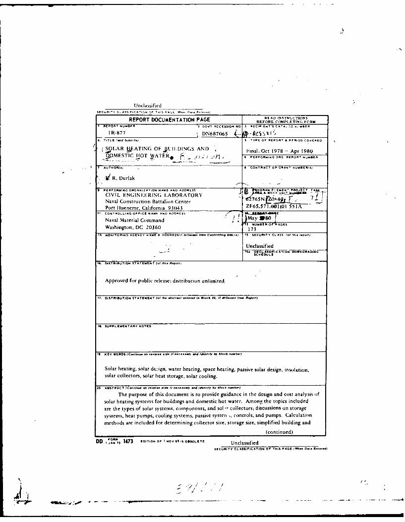
I
UnclassifiedSECURITY CL ASSiFICATIC,, or -"S OAGE P-., F-1-d
REPORT DOCUMENTATION PAGE FREAD INSTRUCTIONSBEFORE COMPLETING FORM
I REPORT NUMBFR !2 GOVT ACCESSION NO I RECIPIENT'S CATALIG NNSBER
TR-877 I DN687065 i--. -eCVAI'
4 TITLE (end SN birte) S TYPE O REPORT I PERIOD CODERED
OLAR JkATING OF .UIIDINGS AND Final; Oct 1978 - Apr 1980DOMESTIC HOT WATE.R..* r*4 PERFORMING ORG RPORT NUMBER
7"AUTHOR(.) . 0 CONTRACT OR GRANT NUMBERe.)
St" R. Durlak
9 PERFORMING ORGANIZATION NAME AND ADDRESS C
CIVIL ENGINEERIN(; I.ABORATORY -- ,5RZO', UI"T o "It
Naval Construction Battalion Center F'765No -- s
Port Ilueneme, California 93043 ZF65.571.001;0l 55 IA11 CONTROLLING OFFICE NAME ANO A3SORESS -"a I ..ZB'4
Naval Material Command , ) WE E'll NUMBER 07 PAGEs
Washington, DC 20360 17311 MONITORING AGENCY NA ME A1 ADORESS,,, d ,3eN. CIon9R, Ol,1) I SECURITI C L ASl S* InIF po,
' • Unclassified1S, OECLASSiPICATION OOWNGNAOIMGSCN DULE
16. DISTIBUTION ST AT EMENIT (.1 Phis Rept,.,
Approved for public release; distribution unlimited.
17. OISTRIBUTION STATEMENT (of Ph. absrt ent.e, d in Bor 20. It 9dIIf-ent INM, Revolt)
II. SUPPLEMENTARY NOTES
I. KEY WORDS (C-oIInu.- ... doIt -.... ry And Id-pIttfy b1 .-ock nAmber)
Solar heating, solar dt:ign, water heating, space heating, passive solar design, insolation,solar collectors, solar heat storage, solar cooling.
20 ABSTRACT (Conlin- - -.- Fide it. P-.y ond identify AI bhck ihmb)
The purpose of this document is to provide guidance in the design and cost analysis ofsolar heating systems for buildings and domestic hot water. Among the topics includedare the types of solar systems, components, and sol ,r collectors; discussions on storagesystems, heat pumps, cooling systems, passive systen I, controls, and pumps. Calculation
methods are included for determining collector size, storage size, simplified building and
(continued)
DD I 1473 EDITION 0I NOV45 IS OBSOLETE Unclassified
SECURITY CLASSIFICATION OF THIS PAGE (Wen D.FI gEte-d)
-. /,
• qqlt. .,€ ) '- '- -4-- -
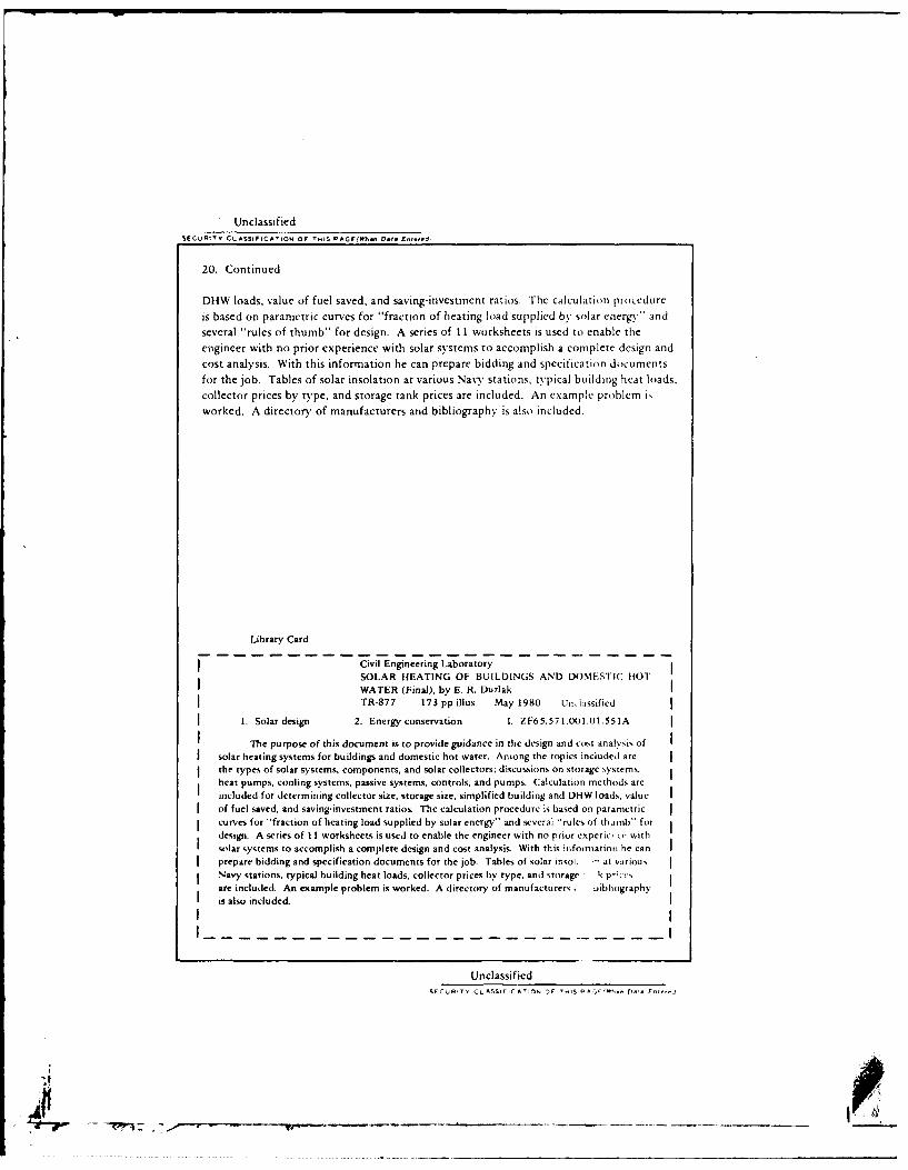
UnclassifiedSECJRITY CLASSlFICAA,1O OF T.1S PAGE(t"W5 D,. E ,Aeed.
20. Continued
DHW loads, value of fuel saved, and saving-investment ratios. The calculation procedurcis based on parametric curves for "fraction of heating load supplied by solar energy" andseveral "r-ules of thumb" for design. A series of 11 worksheets is used to enable theengineer with no prior experience with solar systems to accomplish a complete design andcost analysis. With this information he can prepare bidding and specification documentsfor the job. Tables of solar insolation at various Navy stations, typical building heat loads,collector prices by type, and storage tank prices are included. An example problem i,worked. A directory of manufacturers and bibliography is also included.
Library Card
Civil Engineering LaboratorySOLAR HEATING OF BUILDINGS AND DOMESTIC HOTWATER (Final), by E. R. DurlakTR-877 173 pp illus May 1980 UnL. iassified
1. Solar design 2. Energy conservation 1. ZF65.571.00l.1.551A
The purpose of this document is to provide guidance in the design and cost analysis ofsolar heating systems for buildings and domestic hot water. Among the topics includcd arethe types of solar systems, components, and solar collectors; discussions on storage systems.heat pumps, cooling systems, passive systems, controls, and pumps. Calculation methods areincluded for determining collector size, storage size, simplified building and DHW loads, value
of fuel saved, and saving-investment ratios. The calculation procedure is based on parametriccurves for "fraction of heating load supplied by solar energy" and several 'rules of thumb" fordesign. A series of II worksheets is used to enable the engineer with no prior experice,. withsolar systems to accomplish a complete design and cost analysis. With this infomation he canprepare bidding and specification documents for the job. Tables of solar insoi. " at variousNavy stations, typical building heat loads, collector prices by type, and storage k p ',are included. An example problem is worked. A directory of manufacturers; uibliographyis also included.
UnclassifiedSECuRIT, CL ASSIKrCA'IOs or ,)F AS A '. .,, r-A, FnUAr1,
-, ~--- .t~t~-4 -U S.

A" A05 b15 CIVIL ENGINEERING LAB (NAVY) PORT HUENEME CA F/G 13/1S04.AR I*ATING OF BUILDINGS AND DOMESTIC HOT WATER. REVISION.(U)MAY AGE B DURLAK
UNCLASSIFIlED CEL-TR-877 NL.'EE~hEE71

SUPPLEMENTARY
I
CIVIL ENGINEERING LABORATORYNAVAL CONSTRUCTION BATTALION CENTER
PORT HUENEME, CA 93043 IN REPLY REFER TO
L08/PDT/jwZF65. 571.001.01.551ASerial 129029 Jul 80
'4
From: Officer in ChargeTo: Distribution
Subj: New Table of Contents for Technical Report TR-877, "Solar Heating of
JBuildings and Domestic Hot Water," by E. R. Durlak
1. Please remove pages iii, iv, v, vi, and vii and replace with new corrected
enclosures (Table of Contents).
P. D. TRIEMBy direction
m ...
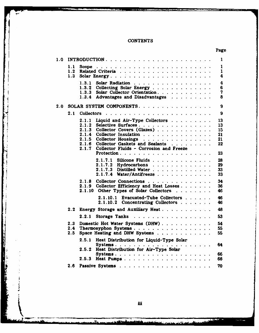
CONTENTS Pg
1.0 INTRODUCTION. .. .. ..... ..... ...... .... 1
1.1 Scope. .. ... ...... ...... ...... ... 11.2 Related Criteria. .. .... ..... ...... .....1.3 Solar Energy. . ... .. .... ..... ...... ... 4
1.3.1 Solar Radiation. .. ... ...... ....... 41.3.2 Collecting Solar Energy .. .. .... ....... 61.3.3 Solar Collector Orientation .. .. .. ........ 71.3.4 Advantages and Disadvantages. .. ..... ... 8
2.0 SOLAR SYSTEM COMPONENTS. .. .. .... ...... ... 92.1 Collectors .. .. ..... ...... ...... .... 9
2.1.1 Liquid and Air-Type Collectors. .. .. ...... 132.1.2 Selective Surfaces .. .. ... ..... ...... 132.1.3 Collector Covers (Glazes) .. .. .... ...... 152.1.4 Collector Insulation. .. ... ..... ...... 212.1.5 Collector Housings .. ... ..... ....... 212.1.6 Collector Gaskets and Sealants .. ... ...... 222.1.7 Collector Fluids - Corrosion and Freeze
Protection. .. .. .... ...... ....... 232.1.7.1 Silicone Fluids .. .. .... ....... 282.1.7.2 Hydrocarbons .. .. ...... .... 292.1.7.3 Distilled Water .. .. .... ....... 332.1.7.4 Water/Antifreeze .. .. .... ...... 33
2.1.8 Collector Connections .. .. ..... ....... 342.1.9 Collector Efficiency and Heat Losses. .. .. .... 362.1.10 Other Types of Solar Collectors .. .. ...... 46
2.1.10.1 Evacuated-Tube Collectors .. .. .... 462.1.10.2 Concentrating Collectors .. .. ..... 46
2.2 Energy Storage and Auxiliary Heat .. .. ... ...... 48
2.3 . Storage Tanks .. ... ..... ...... ....23Domestic Hot Water Systems (DHW) .. .. ... ...... 5424Thermosyphon Systems .. .. ... ...... ...... 552.5SpceHeating and DHW Systems .. .. ..... ..... 55
251Heat Distribution for Liquid-Type SolarSystems .. .. ... ..... ...... ....
2.5.2 Heat Distribution for Air-Type SolarSystems .. .. ... ..... ...... .... 66
2.5.3 Heat Pumps. .. .. ..... ...... .... 66
2.6 Passive Systems .. .. ..... ...... ....... 70
A& Mi
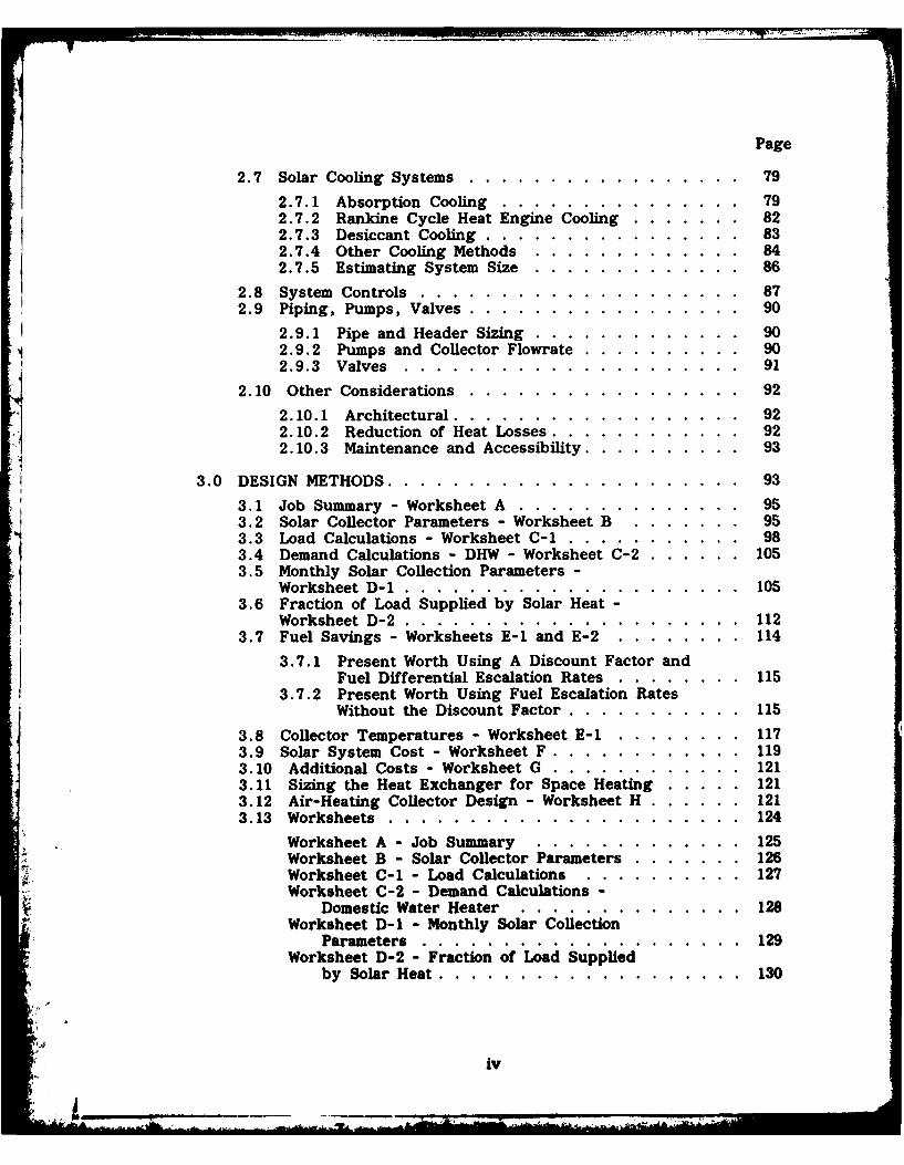
Page
2.7 Solar Cooling Systems. .. .... ..... ....... 79
2.7.1 Absorption Cooling. .. .... ..... ..... 792.7.2 Rankine Cycle Heat Engine Cooling .. .. ..... 822.7.3 Desiccant Cooling .. .. .... ...... ... 832.7.4 Other Cooling Methods .. ... ...... ... 842.7.5 Estimating System Size .. ... ..... ..... 86
2.8 System Controls. .. .... ..... ..... .... 872.9 Piping, Pumps, Valves .. .. .... ..... ...... 90
2.9.1 Pipe and Header Sizing .. .. ..... ...... 902.9.2 Pumps and Collector Flowrate. .. ... ...... 902.9.3 Valves. .. .... ...... ..... ..... 91
2.10 Other Considerations. .. .... ..... ....... 922. 10. 1 Architectural. .. .. .... ...... ..... 922.10.2 Reduction of Heat Losses. .. .. ..... ... 922.10.3 Maintenance and Accessibility .. .. .. ...... 93
3.0 DESIGN METHODS .. .. .. ...... ..... ....... 93
3.1 Job Summary - Worksheet A. .. .... ..... ... 953.2 Solar Collector Parameters - Worksheet B. .. ...... 953.3 Load Calculations - Worksheet C-1i.. .. ..... ... 983.4 Demand Calculations - DHW - Worksheet C-2. .. .. .. 1053.5 Monthly Solar Collection Parameters -
Worksheet D-1 .. .. .... ............. 1053.6 Fraction of Load Supplied by Solar Heat-
Worksheet D-2 .. .. .... ...... ..... ... 1123.7 Fuel Savings - Worksheets E-1 and E-2. .. .... .. 114
3.7.1 Present Worth Using A Discount Factor andFuel Differential Escalation Rates. .. .... .. 115
3.7.2 Present Worth Using Fuel Escalation RatesWithout the Discount Factor. .. .. ..... .. 115
3.8 Collector Temperatures - Worksheet E-1 1. .. ...... 1173.9 Solar System Cost -Worksheet F. .. .. ..... ... 1193.10 Additional Costs -Worksheet G. .. ... ..... .. 1213.11 Sizing the Heat Exchanger for Space Heating .. .. .. 1213.12 Air-Heating Collector Design - Worksheet H. .. .. .. 1213.13 Worksheets .. .. ..... ...... ..... ... 124
Worksheet A - Job Summary .. .... ..... ... 125Worksheet B - Solar Collector Parameters. .. ... .. 126Worksheet C-1 - Load Calculations. .. ..... ... 127Worksheet C-2 - Demand Calculations -
Domestic Water Heater .. .... ..... ..... 128Worksheet D-1 - Monthly Solar Collection
Parameters. .. ................. 129Worksheet D-2 - Fraction of Load Supplie~d'
by Solar Heat .. .. ... ...... ..... .. 130
iv
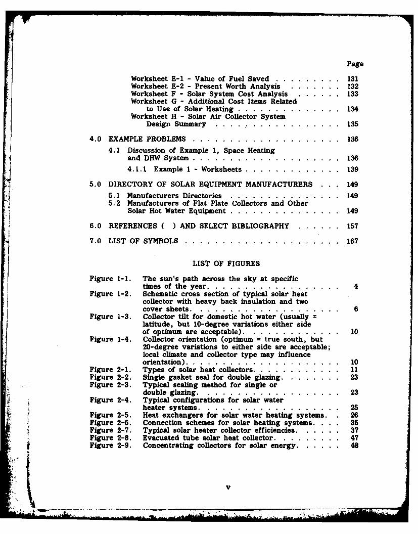
Page
Worksheet E-1 - Value of Fuel Saved .... ......... 131Worksheet E-2 - Present Worth Analysis ... ....... 132Worksheet F - Solar System Cost Analysis ... ...... 133Worksheet G - Additional Cost Items Related
to Use of Solar Heating ..... .............. 134Worksheet H - Solar Air Collector System
Design Summary ....... .... ............. 135
4.0 EXAMPLE PROBLEMS ..... .................... ... 136
4.1 Discussion of Example 1, Space Heatingand DHW System ...... .................... .. 136
4.1.1 Example 1 - Worksheets ..... ............. 139
5.0 DIRECTORY OF SOLAR EQUIPMENT MANUFACTURERS . . . 149
5.1 Manufacturers Directories .... ............... ... 1495.2 Manufacturers of Flat Plate Collectors and Other
Solar Hot Water Equipment ..... ............... 149
6.0 REFERENCES ( ) AND SELECT BIBLIOGRAPHY ... ...... 1577.0 LIST OF SYMBOLS ... ........................ 167
LIST OF FIGURES
Figure 1-1. The sun's path across the sky at specifictimes of the year ....... .................. 4
Figure 1-2. Schematic cross section of typical solar heatcollector with heavy back insulation and twocover sheets. ............................... 6
Figure 1-3. Collector tilt for domestic hot water (usually =latitude, but 10-degree variations either sideof optimum are acceptable) ..... ............. 10
Figure 1-4. Collector orientation (optimum = true south, but20-degree variations to either side are acceptable;local climate and collector type may influenceorientation) ......................... .... 10
Figure 2-1. Types of solar heat collectors ............... ... 11Figure 2-2. Single gasket seal for double glazing ........... 23Figure 2-3. Typical sealing method for single or
double glazing ....... ................... 23Figure 2-4. Typical configurations for solar water
heater systems ..... ................... ... 25Figure 2-5. Heat exchangers for solar water heating systems. 26Figure 2-6. Connection schemes for solar heating systems. 35Figure 2-7. Typical solar heater collector efficiencies ......... 37Figure 2-8. Evacuated tube solar heat collector .... ......... 47Figure 2-9. Concentrating collectors for solar energy ......... 48
v
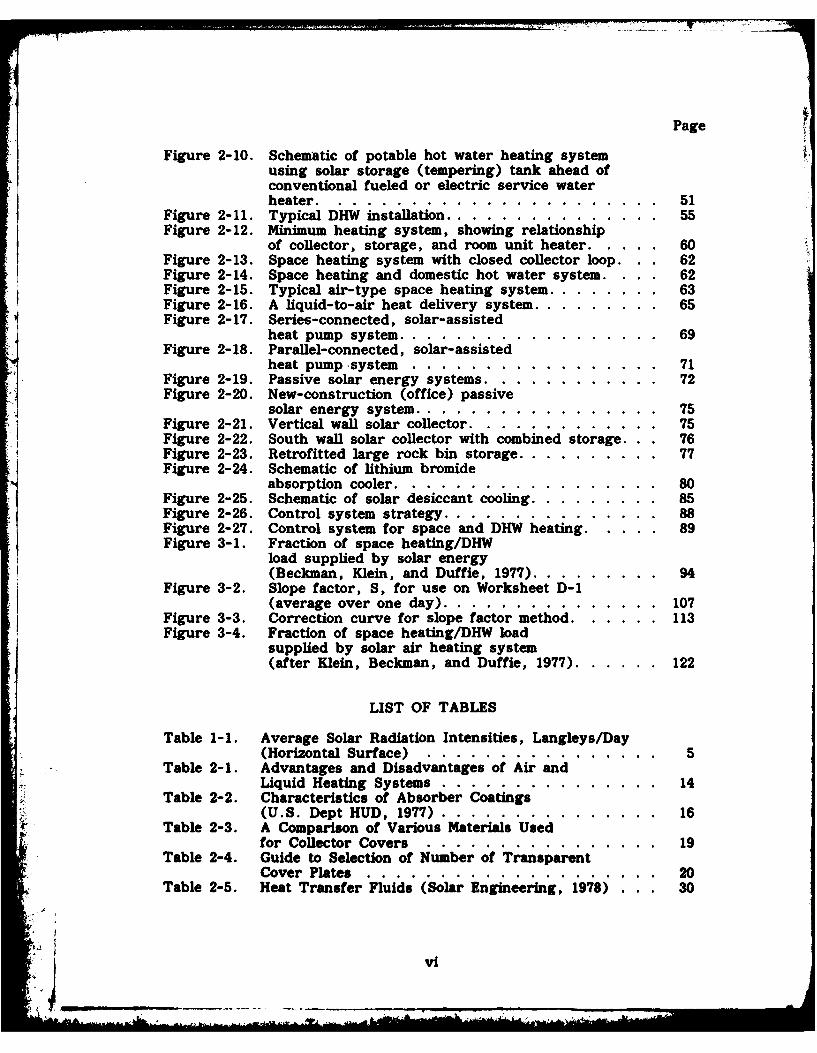
Page
Figure 2-10. Schematic of potable hot water heating systemusing solar storage (tempering) tank ahead ofconventional fueled or electric service waterheater.....................51
Figure 2-11. Typical DHW in staition..............55Figure 2-12. Minimum heating system, showing relationship
of collector, storage, and room unit heater .. .. ... 60Figure 2-13. Space heating system with closed collector loop . 62Figure 2-14. Space heating and domestic hot water system. . 62Figure 2-15. Typical air-type space heating system .. .. .. .... 63Figure 2-16. A liquid-to-air heat delivery system .. .. .. ..... 65Figure 2-17. Series-connected, solar-assisted
heat pump system. .. .. .... ..... ...... 69Figure 2-18. Parallel-connected, solar-assisted
heat pump -system. .. ..... ..... ...... 71*Figure 2-19. Passive solar energy systems .. .. .... ...... 72
Figure 2-20. New-construction (office) passive.4solar energy system ... .. ... ...... ..... 75
Figure 2-21. Vertical wall solar collector. .. .. ..... ..... 75Figure 2-22. South wall solar collector with combined storage . 76Figure 2-23. Retrofitted large rock bin storage .. .. .. ...... 77Figure 2-24. Schematic of lithium bromide
absorption cooler .. .. ..... . ...... ... 80
Figure 2-25. Schematic of solar desiccant coln.. .. ... .... 85Figure 2-26. Control system strategy .. .. .. ...... ..... 88Figure 2-27. Control system for space and DHW heating .. .. ... 89Figure 3-1. Fraction of space heating/DHW
load supplied by solar energy* (Beckman, Klein, and Duffie, 1977) .. .. ... .... 94
Figure 3-2. Slope factor, S, for use on Worksheet D- 1(average over one day). .. .. .... ........ 107
Figure 3-3. Correction curve for slope factor method. .. .. .. 113Figure 3-4. Fraction of space heating/DIN load
supplied by solar air heating system(after Klein, Beckman, and Duffie, 1977). .. .. .. 122
LIST OF TABLES
Table 1-1. Average Solar Radiation Intensities, Langleys/Day(Horizontal Surface) .. .... ...... ...... 5
Table 2-1. Advantages and Disadvantages of Air andLiquid Heating Systems. .. .... ..... ..... 14
Table 2-2. Characteristics of Absorber Coatings(U.S. Dept HUD, 1977). .. ... ...... ..... 16
Table 2-3. A Comparison of Various Materials Usedfor Collector Covers .. .... ...... ...... 19
Table 2-4. Guide to Selection of Number of TransparentCover Plates .. ... ...... ..... ...... 20
Table 2-5. Heat Transfer Fluids (Solar Engineering, 1978) . .. 30
vi
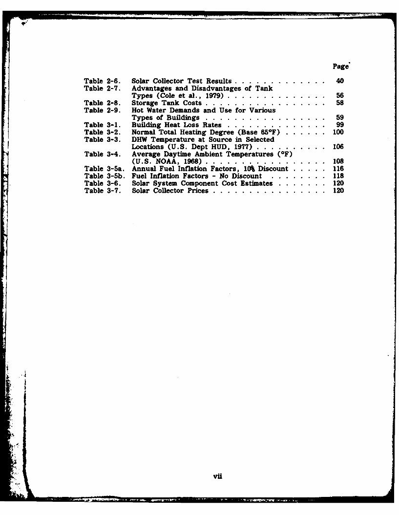
Page
Table 2-6. Solar Collector Test Results ................ ... 40Table 2-7. Advantages and Disadvantages of Tank
Types (Cole et al., 1979) ..... .............. 56Table 2-8. Storage Tank Costs ...... ................. 58Table 2-9. Hot Water Demands and Use for Various
Types of Buildings .... ................. ... 59Table 3-1. Building Heat Loss Rates ...................... 99Table 3-2. Normal Total Heating Degree (Base 65F) ...... .. 100Table 3-3. DHW Temperature at Source in Selected
Locations (U.S. Dept HUD, 1977) .......... 106Table 3-4. Average Daytime Ambient Temperatures (IF)
(U.S. NOAA, 1968) ...... ................. 108Table 3-5a. Annual Fuel Inflation Factors, 10% Discount ....... 116Table 3-5b. Fuel Inflation Factors - No Discount .......... ... 118Table 3-6. Solar System Component Cost Estimates ......... .. 120Table 3-7. Solar Collector Prices .... ................ ... 120
vii


![AD-A285 189 I[111] 1j111, INi! 11 II l fll - dtic. · PDF fileof Engineers I[111] 1j111, INi! 11 II .i l fll Waterways Experiment Station In-House Laboratory Independent Research Program](https://img.pdfslide.us/doc/110x75/5a7c935a7f8b9a563b8cfa97/ad-a285-189-i111-1j111-ini-11-ii-l-fll-dtic-engineers-i111-1j111-ini.jpg)


![]iii 111 a 11i mu nln081 I - DTIC](https://img.pdfslide.us/doc/110x75/61824d8eeea4dd6b6c7522e6/iii-111-a-11i-mu-nln081-i-dtic.jpg)