Embed Size (px)
Citation preview

110Nm Manual – Sep 16 Page 1 of 40
INSTALLATION AND MAINTENANCE
INSTRUCTIONS FOR THE
110NM COMPACT
SINGLE STATION
WINDSCREEN WIPER SYSTEM

110Nm Manual – Sep 16 Page 2 of 40
CONTENTS GENERAL INFORMATION AND SAFETY SUMMARY ................................................................... 4
SAFETY PRECAUTIONS ............................................................................................................... 4
INTRODUCTION ............................................................................................................................ 4
VARI-ARC LEVER SETTINGS ....................................................................................................... 4
ABBREVIATIONS AND DEFINITIONS ........................................................................................... 4
DESCRIPTION OF WIPER SYSTEM ............................................................................................. 5
WIPER MOTOR ASSEMBLY – RH BRACKET ............................................................................... 5
WIPER MOTOR ASSEMBLY – LH BRACKET ................................................................................ 6
ELECTRICAL CONNECTIONS ....................................................................................................... 6
EXPLODED VIEW OF LINKAGE .................................................................................................... 7
WIPER ARM ASSEMBLY ............................................................................................................... 8
INSTALLATION INSTRUCTIONS ................................................................................................... 8
DRILLING DIAGRAM .................................................................................................................... 10
DRILLING DIAGRAM .................................................................................................................... 11
FITTING THE WIPER UNIT .......................................................................................................... 12
VARI ARC UNITS – ARC ADJUSTMENT ..................................................................................... 13
FITTING THE WIPER BLADE ....................................................................................................... 14
FITTING THE WIPER ARM ASSEMBLY ...................................................................................... 15
ADJUSTING THE WIPER BLADE ANGLE ................................................................................... 17
TROUBLESHOOTING – TABLE ................................................................................................... 18
INTRODUCTION .......................................................................................................................... 18
SAFETY PRECAUTIONS ............................................................................................................. 18
TROUBLESHOOTING PROCEDURES ........................................................................................ 18
TROUBLESHOOTING TABLE ...................................................................................................... 18
TROUBLESHOOTING TABLE – CONTINUED ............................................................................. 19
MAINTENANCE – TABLE ............................................................................................................. 20
INTRODUCTION .......................................................................................................................... 20
SAFETY PRECAUTIONS ............................................................................................................. 20
SCHEDULED MAINTENANCE ACTION CHECK ......................................................................... 20
MAINTENANCE TABLE ................................................................................................................ 20
MAINTENANCE TABLE – CONTINUED ....................................................................................... 21
HOW TO CHECK FOR WEAR ON THE ROD END ...................................................................... 21
MAINTENANCE INSTRUCTIONS ................................................................................................ 22
TO REPLACE THE WIPER BLADE .............................................................................................. 23
TO REPLACE THE WIPER ARM .................................................................................................. 24
TO REMOVE THE ENTIRE WIPER MOTOR UNIT ASSEMBLY .................................................. 25
TO REPLACE THE DRIVE CRANK ASSEMBLY .......................................................................... 26
TO REPLACE THE WIPER MOTOR ............................................................................................ 27

110Nm Manual – Sep 16 Page 3 of 40
TO REPLACE THE TIE BAR ........................................................................................................ 28
TO REPLACE THE LEVER/LINER/SPINDLE SUB ASSEMBLY ................................................... 29
CONTROLLER INSTALLATION INSTRUCTIONS ........................................................................ 30
12V OR 24V MULTI-SWITCH – WIRING & SIZES ....................................................................... 31
12V OR 24V MULTI-SWITCH – OPERATION .............................................................................. 32
12V/24V ROTARY SWITCH – WIRING & SIZES .......................................................................... 33
12V/24V ROTARY SWITCH – OPERATION ................................................................................. 34
12V/24V TOGGLE SWITCH – WIRING & SIZES .......................................................................... 35
12V/24V TOGGLE SWITCH – OPERATION ................................................................................. 36
EXTERNAL FITTINGS – ARMS .................................................................................................... 37
EXTERNAL FITTINGS – LINKAGE............................................................................................... 38

110Nm Manual – Sep 16 Page 4 of 40
GENERAL INFORMATION AND SAFETY SUMMARY As we will have no influence on the installation of complete windscreen wiper systems if installation is to be carried out by the customer, we are unable to accept liability for installation errors.
If you require any additional information or any special problems arise which the installation/maintenance instructions do not treat in sufficient detail please contact Customer Service at B. Hepworth and Co Ltd directly.
Safety Precautions
CAUTION! BEWARE OF INJURY! BEFORE WORKING ON THE WIPER SYSTEM, OBSERVE THE FOLLOWING REMARKS WITHOUT FAIL! Most wiper motors have a park setting, which permits them to default to the parked position if connected to the vehicle electrical system, even when the wiper is switched off. FOR THIS REASON, AT THIS POINT IN TIME, NEITHER MAY THE WIPER ARM BE MOUNTED, NOR MAY ANY PERSON HAVE HANDS, FINGERS, ETC ANYWHERE NEAR THE WIPER SYSTEM. Even small wiper motors can neither be braked nor stopped by hand. NEVER REACH INTO THE AREA OF THE ROD LINKAGE WHEN THE SYSTEM IS RUNNING! When putting into service (i.e. when connecting the wiper motor to the vehicle electrical system, even if the wiper switch is in the 0 position), never leave any loose items such as screwdrivers in the area of the wiper system, as flying objects could lead to injury.
Please ensure the equipment is handled with care. Do not drop or bang the equipment down on a hard surface taking extra care around the area where the motor shaft is situated. Do not hammer the motor shaft when installing the equipment, as this will cause the motor gear plate to deform causing premature failure of the unit.
Introduction The Windscreen Wiper system utilised is detailed on the following pages. The primary components that form the Windscreen Wiper System are the wiper motor linkage, the wiper arm assemblies and the wiper blades.
Vari-Arc Lever Settings
IMPORTANT Vari-arc levers which have been factory set will be torqued and paint marked. Do not adjust. Unpainted lever nuts must be torque tightened M8 = 20Nm, prior to the unit being fitted.
Where internal fixing screws and/or nuts are factory set and paint marked, leave untouched unless required to be changed or paint mark is damaged.
Abbreviations and Definitions
Abbreviation Definition Abbreviation Definition
Assy Assembly LH Left Hand
Brk Bracket RH Right Hand
D. Crk Drive Crank S.A. Sub Assembly

110Nm Manual – Sep 16 Page 5 of 40
Figure 1
DESCRIPTION OF WIPER SYSTEM The wiper motor and bracket is shown in Figures 1, 2 & 4. The electric wiper motor forms the central part of the windshield wiper system. The motor is mounted on a fabricated mild steel bracket which is polyester powder coated to prevent corrosion. The motor is connected electrically by means of a multi-pin connector. Ref Figure 3 The drive lever is secured to the wiper motor shaft and connected through a tie bar, to the spindle lever assembly. These components transfer the motor shaft rotation to the wiper arm assemblies. The drive mechanism provided transfers the rotary output from the motor; to a reciprocating motion of the spindles, this mechanism is zinc plated and is sized to give the correct angle of arc for the windscreen wiper arm being driven. The Spindles that drive the wiper arms pass through the bulkhead, connecting the drive mechanism to the wiper arm; these are manufactured from stainless steel, to prevent corrosion. The spindles are driven from the main drive crank by connecting tie bars which distributes the load evenly between the arms of the wiper arm thus reduces the load on the individual interfaces between the wiper arm and the spindles.
Wiper Motor Assembly – RH BRACKET
110Nm
Motor
Drive Crank
Sub Assy
- 50 Crs
188.5
85 30
163Connecting
Tie Bar
RIGHT HAND
BRACKET
STANDARD PARK
SHOWN
OPPOSITE HAND PARK
Front Face of Bkt
Shown in Dotted
Line for Clarity
Tie Bar
Vari-Arc
Liner/Lever
Sub Assy
Driven Idler
Liner/Lever
Sub Assy
Motor Mounting
Bracket Weld Assy
60
473
13 176
38.5 125
25
95
192
25
50 347 ±1mm CRS

110Nm Manual – Sep 16 Page 6 of 40
Figure 3
WIRING CONNECTION CODE
31 0v DC (-ve) Supply
53 Slow Speed
53b Fast Speed
53a 24v DC (+ve) Supply & Self Park
31b Self Park – Reversal Speed
53b53
31
31b
53a
53
53b
31b
53a
31
31b
53
53a
53b
31
31
53a53
31b 53b
M
SELF PARKREVERSALFEED SLOW FAST
& SELFPARKFEED
(+VE)24v DC
SUPPLY
(+VE)
24v DC
SUPPLY
0v DC
(-VE)
(8)
(4)
(6)
(2)
MOTOR CONNECTOR
(SHOWN ROTATED 180°)
(FRONT VIEW)
SHOWN IN OFF/PARK
CONFIGURATION
Figure 2
Wiper Motor Assembly – LH BRACKET
Electrical Connections
53
162
85
188.5
Tie Bar
Vari-Arc
Liner/Lever
Sub Assy
Driven Idler
Liner/Lever
Sub Assy
110Nm
Motor
Drive Crank
Sub Assy - 50 Crs
Motor Mounting
Bracket Weld Assy
60
473
13176
38.5125
2560
95
192
25
50347 ±1mm CRS
Connecting
Tie Bar
LEFT HAND
BRACKET
STANDARD PARK
SHOWN
OPPOSITE HAND PARK
Front Face of
Bkt Shown in
Dotted Line
for Clarity

110Nm Manual – Sep 16 Page 7 of 40
ITEM DESCRIPTION QTY ITEM DESCRIPTION QTY
1 Motor Mounting Bracket 1 9 26mm Washer - Neoprene 2
2 Liner V.Arc Lever Sub Assy 1 10 26mm Washer – Flat 2
3 Idler Liner Sub Assy 1 11 26mm Washer – Single Coil 2
4 Drive Crank Sub Assy 40 Crs 1 12 M26 Hex. Nut 2
5 Tie Bar – 280mm Overall 1 13 26mm Weather Cap 2
6 110Nm (IER) Motor 1 14 10mm Washer - Flat 2
7 Idler Plate - Gasket 1 15 M10 Nylock Nut 2
8 Idler Plate 1 16 10mm Nut Weather Cap 2
Figure 4
LEFT HAND
BRACKET
RIGHT HAND
BRACKET
1
4
8
10
12
1416
79
11
1315
56
2
5a
3
Exploded View of Linkage

110Nm Manual – Sep 16 Page 8 of 40
Wiper Arm Assembly The wiper arm is manufactured from stainless steel and is polyester powder coated to prevent corrosion and to be of good appearance. The wiper arm is shown below. One wiper arm assembly is used on each unit. The wiper arm assembly mounts directly onto the spindles protruding through the bulkhead. The wiper arm is secured to the spindle via a series of nuts and washers. The blade is secured to the arm assembly using the blade clip arrangement on the arm and blade bolt.
P84 ARMS 24" (NOM. 710mm)
TO 46" (NOM 1170mm)
1 x HEAVY DUTY HEAD
P84 ARMS 47"
(NOM. 1195mm) & OVER
2 x HEAVY DUTY HEADS
3
2
14
16
15
5
60 CRS
4
1
6
15
14
5
ITEM DESCRIPTION QTY
1 P84 Wiper Arm 1
2 Articulated Curved Blade 1
3 Blade Retaining Screw 1
4 Nylock Nut 1
5 Arm Head Weather Cap 1
6 Wash Jet Assy 1
7 Ecoprene Wash Tube Metres
The Following Items Are On The Linkage
14 10mm Washer - Flat 2
15 M10 Nylock Nut 2
16 10mm Nut Weather Cap 2
IMPORTANT On arms with 2 x heavy duty heads the arc of wipe on the linkage MUST NOT exceed 70º

110Nm Manual – Sep 16 Page 9 of 40
INSTALLATION INSTRUCTIONS NOTE Retain all items removed in a safe place, as they will be required on reassembly. Any item to be discarded must be done in accordance to vessels manufacturer described task guidelines If you experience any difficulty in the fitting of any of the units/components, please do not hesitate to contact Customer Service at B. Hepworth & Co. for advice. Use the drawings for reference.
WARNING: Isolate the electrical supply before commencing any fitting work on any part of the wiper system.

110Nm Manual – Sep 16 Page 10 of 40
Drilling Diagram NOTE – Drilling Diagram is NOT to size and is for reference only
DR
ILLIN
G D
IAG
RA
M -
FO
R 1
10N
m R
IGH
T H
AN
D B
RA
CK
ET
UN
ITS
6095
125
25.5
25.5
'A'
'B'
259
60
176
'C'
'C'
'C'
'C'
'C'
'C'
55
Drill
hole
s 'A
' and 'B
' at
Ø30m
m (
Note
Hole
'B
' n
ot re
quire
d o
n P
endulu
m u
nits)
Drill
hole
'C
' at
Ø8.5
mm
(6
options s
how
n)

110Nm Manual – Sep 16 Page 11 of 40
Drilling Diagram NOTE – Drilling Diagram is NOT to size and is for reference only
Drill
hole
s 'A
' and
'B
' at Ø
30m
m (
Note
Ho
le 'B
' not re
quir
ed o
n P
endu
lum
un
its)
Drill
hole
'C
' at Ø
8.5
mm
(6 o
ptio
ns s
how
n)
6095
12
52
5.5
25
.5
'A'
'B'
25
9
60
17
6
'C'
'C'
'C'
'C'
'C'
'C'
55
DR
ILL
ING
DIA
GR
AM
- F
OR
11
0N
m L
EF
T H
AN
D B
RA
CK
ET
UN
ITS

110Nm Manual – Sep 16 Page 12 of 40
FITTING THE WIPER UNIT
IMPORTANT Vari-arc levers which have been factory set will be torqued and paint marked. Do not adjust. Unpainted lever nuts must be torque tightened M8 = 20Nm, prior to the unit being fitted. Ref Figure – Drilling Diagram
When the spindle positions have been drilled in the bulkhead, the following procedures apply.
Ref Figure 2 – Exploded Diagram
On all units –
1. Remove from each spindle one weather cap (16), one M10 nut (15), one washer – flat (14) 2. Remove from each liner, one weather cap (13), one M26 nut (12), one washer – single coil
(11), one washer – flat (10), and one washer – neoprene (9) On Pantograph units only –
3. Remove idler plate (8) and finally idler gasket (7) NOTE the Motor Unit is MOUNTED from INSIDE the Bulkhead.
4. Fit motor unit and fix in place through predrilled mounting holes (Fixing bolts not supplied) 5. Externally – ENSURE a proprietary sealant (Not supplied) is used around all points of entry
through bulkhead. On Pantograph units only –
6. Fit following items – one idler gasket (7) and one idler plate (8) over both liners, next to bulkhead.
On all units –
7. Fit following items – Onto each liner, one washer – neoprene (9), one washer – flat (10), one washer – single coil (11), one M26 nuts (12) Torque M26 = 30Nm (on Brass Liner Nut) Torque M26 = 50Nm (on SS Liner – G.R.P. – Nut) Torque M26 = 80Nm (on SS Liner – Metal Structure – Nut)
8. Fit onto each liner, one M26 weather cap (13), ensuring that it sits tightly around spindle shaft. 9. Internally – Wire motor to vessels electrics via switch/controller (May or/may not be
supplied) With Reference to Fitting Instructions – Electrical Connections

110Nm Manual – Sep 16 Page 13 of 40
90° 56 (90°)
59 (85°)
63 (80°)
66 (75°)
71 (70°)
74.5 (65°)
80 (60°)
87.5 (55°)
95 (50°)
105 (45°)
120 (40°)
9.5
160 O/A
25.4
ITEM DESCRIPTION QTY
2 Liner V.Arc Lever Sub Assy 1
23 12mm Right Hand Bearing Nut 1
24 12mm Right Hand Bearing 1
25 8mm Washer – Flat 1
26 M8 Securing Nylock Nut 1
27 V.Arc Bearing Pivot Pin 1
23
2
25
2624
27
VARI ARC UNITS – ARC ADJUSTMENT IMPORTANT Vari-arc levers which have been factory set will be torqued and paint marked. Do not adjust. Unpainted lever nuts must be torque tightened M8 = 20Nm, prior to the unit being fitted.
1. Internally – Run Motor to insure it is parked correctly. Disconnect all Electrical Power. 2. Slacken bearing nuts at both ends of tie bar and securing Nylock nut (26) on Vari arc lever. 3. Slide bearing/tie bar assembly pivot pin (27) towards liner/spindle assembly to increase arc
to 90° max or away from liner/spindle assembly to decrease arc to 40° min. 4. Ensure you note markings on lever when correct arc is reached. Important: Pantograph
Systems must not exceed 90° arc of wipe. 5. Adjust arc until blade parks approximately 75-100mm from edge of screen when screen is
dry. Test on a wet screen to prove clearance is acceptable. 6. Tighten bearing nuts at both ends of tie bar and securing Nylock nut (26) 7. Tighten securing Nylock nut (26) on Vari arc lever
Torque M8 = 20Nm (on Arm – V.A. lever)
IMPORTANT: Ensure BEARING CENTRES are as stated in drawing, Figure 1

110Nm Manual – Sep 16 Page 14 of 40
FITTING THE WIPER BLADE The wiper blades should be changed every 12 months but this is dependent on use and operating conditions
With reference to the Maintenance Table and the Troubleshooting Table – Continued
Ref Figure – Blade Clip Fixings
1. Remove blade retaining screw (1), and M4 Nylock nut (2), from blade clip on arm. NOTE No plastic spacers required – if supplied with blade
If only one end of the wiper blade rubber is captive, it must be fitted so it will be at the top of the screen when the arm is in the vertical position. (Articulated blades only)
Ref Figure – Blade Captive End
2. Place wiper blade directly into arm blade clip. 3. Ensure that all fixing holes align, on wiper blade
and arm blade clip. Ref Figure – Blade Clip Fixings
4. Secure in place with blade retaining screw (1), and M4 Nylock nut (2).
IMPORTANT DO NOT over tighten blade retaining screw and nut, as blade is required to pivot on glass.
Ref Figure – Nut Tightening
5. Secure nut until tight – then 1/4 turn back NOTE
Pictorial representation only, May not be exact to supplied arm
Figure – Blade Clip Fixings
20mm14mm14mm 4
3
4
3
14mm4
3
4
3
BLADE CLIP BLADE CLIPS for SWIVEL PLATE1 PIECE T. PIECE
PENDULUM PANTOGRAPH
Figure – Blade Captive End
Must be at top
1/4 turn back
Figure – Nut Tightening
Secure nut until tight

110Nm Manual – Sep 16 Page 15 of 40
FITTING THE WIPER ARM ASSEMBLY IMPORTANT: The blade must be fitted to arm prior to arm being fitted. (This is to prevent blade clip damaging screen) 1. Internally – Run motor to insure it is parked correctly. Disconnect all electrical power. 2. Externally – While unit is being run, it is IMPORTANT to observe direction drive spindle
rotates in immediately before it stops. This direction will give PARK POSITION. Pantograph Arms Only:
Ref Figure – Arm Alignment
3. Fit arm onto spindle allowing blade to lay approx 50-75mm from edge of glass in PARKED POSITION. Test on a wet screen to prove clearance is acceptable.
Ref Figure – Arm Fittings
4. Fit one 10mm flat washer (14) on to spindle next to arm head, then one M10 Nylock nut (15), on to each spindle.
5. Only tighten nut sufficiently to allow arm and blade to travel
across glass when motor is run to see if positioning is correct.
6. If incorrectly positioned – DO NOT ATTEMPT TO ROTATE
OR TWIST ARM ON SPINDLE this will damage splined end of drive spindle, resulting in arm and blade slipping in operation.
Ref Figure – Arm Extractor
7. To correct alignment errors, – loosen nut and gently pull arm up spindle, realign and repeat stages above.
Use arm extractor tool to help pull wiper arm up spindle, if required
8. When correctly aligned, tighten M10 spindle nuts
Torque M10 = 38Nm (on Spindle Nut)
9. Fit weather caps supplied with linkage (16) and fit one/two M10 arm weather head caps (5). 10. Carefully push black wash hose attached to wiper arm onto bulkhead connector (Not
Supplied)
IMPORTANT On first fitting check spring pressure on blade in parked position it must NOT exceed recommended pressure 1-1.5kg Pendulum Arms Only:
Ref Figure – Arm Fittings
3. Fit arm onto spindle allowing blade to lay approx 50-75mm from edge of glass in PARKED POSITION. Test on a wet screen to prove clearance is acceptable.
Ref Figure – Arm Fittings
Figure – Arm Alignment
WRONG RIGHT
Figure – Arm Fittings
14
15
5
16
1
Figure – Arm Alignment
WRONG RIGHT

110Nm Manual – Sep 16 Page 16 of 40
4. Fit one 10mm flat washer (14) on to spindle next to arm head, then one M10 Nylock nut (15), on to each spindle.
5. Only tighten nut sufficiently to allow arm and blade to travel
across glass when motor is run to see if positioning is correct.
6. If incorrectly positioned – DO NOT ATTEMPT TO ROTATE
OR TWIST ARM ON SPINDLE this will damage splined end of drive spindle, resulting in arm and blade slipping in operation.
Ref Figure – Arm Extractor
7. To correct alignment errors, – loosen nut and gently pull arm up spindle, realign and repeat stages above. Use arm extractor tool to help pull wiper arm up spindle, if required
8. When correctly aligned, tighten M10 spindle nuts
Torque M10 = 38Nm (on Spindle Nut)
9. Fit weather caps supplied with linkage (16) 10. Carefully push black wash hose attached to wiper arm onto bulkhead connector (Not
Supplied)
IMPORTANT On first fitting check spring pressure on blade in parked position it must NOT exceed recommended pressure 1-1.5kg
Figure – Arm Extractor
2
4
PLAN VIEW
3
Weather Cap
Liner
Arm Head
Spindle End
2. Insert the Extractor between theWeather Cap and the Arm Head
3.Turn Handle to remove Arm
OPERATING THE EXTRACTOR
4. RemoveArm
1
1. Remove Nut Cap, Nylock Nut & Plain
Washers
Arm Head Spindle End
Liner Weather Cap Extractor
Figure – Arm Fittings
1
16
15
14 2

110Nm Manual – Sep 16 Page 17 of 40
Figure – Adjusting the Wiper Blade Angle
25° 25°
WIPER
BLADE
ARM
SWIVEL
PLATE
M5 SCREW
BLADE
CLIP
WASH
JET
WASHER
M5 SCREW
ENLARGED SCRAP VIEW
OF FITTINGS
WASH
TUBE
M5 NUT
NOTE
PICTORIAL REPRESENTATION ONLY
TO SHOW HOW TO ADJUST FITTINGS
MAY NOT BE EXACT TO SUPPLED ARM
ADJUSTING THE WIPER BLADE ANGLE
IMPORTANT Adjusting the Wiper Blade Angle only applies to Pantograph Arms with a Swivel Plate
Ref Figure – Adjusting the Wiper Blade Angle
1. On back of adjustable swivel plate, slacken all M5 screw and nut assemblies to allow movement of blade clip on plate.
2. Rotate blade clip and blade to correct angle. Max 25° about centre. 3. Re-tighten all M5 screw and nut assemblies
Torque M5 = 4.5Nm (on Arm – Swivel Plate/Blade Clip)

110Nm Manual – Sep 16 Page 18 of 40
TROUBLESHOOTING – TABLE
Introduction The following provides all the instructions and information necessary to locate problems and conduct tests on the windscreen wiper system components. The trouble-shooting table is provided for logical isolation of faults.
Safety Precautions Always disconnect the power when servicing the Windscreen Wiper System, or on any ancillary components. Serious damage to the Equipment and/or Personal Injury may occur if the power is not disconnected.
Troubleshooting Procedures Typical windshield wiper system troubleshooting procedures are contained in the Table. These troubleshooting and repair procedures should be followed when encountering operational problems with the windshield wiper system
Troubleshooting Table
SYMPTOM PROBABLE CAUSE TESTS AND CHECKS CORRECTIVE ACTION
Wiper motor fails to start
On/off switch
Voltage Level
System Jammed
Defective wiper motor
Check position of switch
Check supply voltage to switch. Check wiring and switch connections
Check wiper linkage
Turn switch to on position
Replace switch. Correct loose wiring connections. Replace broken wires
Release linkage. Release wiper arm
Replace motor
Motor shaft turns but linkage & arm remain static
Defective or loose drive crank
Check linkage for a loose drive crank
Secure or replace drive crank. Clean motor output shaft with wire brush before replacing.
With Ref to Maintenance Table – continued for Torque settings.
System operates but wiper arm remains static
Wiper arm
Check for loose wiper arm connection onto drive spindle
Secure or replace wiper arm after cleaning spindle spline with wire brush. Torque to M10 = 38Nm
Erratic Motor
Voltage level
Switch
Wiring
Check supply voltage to wiper system
Check for loose or broken wires
Correct voltage supply problem
Replace faulty switch
Repair or replace wiring up to motor. Replace motor if this wiring is damaged

110Nm Manual – Sep 16 Page 19 of 40
Troubleshooting Table – Continued
SYMPTOM PROBABLE CAUSE TESTS AND CHECKS CORRECTIVE ACTION
Slow Motor Operation
Voltage Level
On/off switch
Motor Bracket
Linkage
Defective Wiper Motor
Check supply voltage to wiper system
Check for broken bracket
Check to see if Linkage is free moving
Correct voltage supply problem
Replace faulty switch
Replace defective bracket
Free linkage replace worn or damaged components
Replace Wiper Motor
Arm and blade not operating correctly or over sweep operation
Voltage level
Linkage
Spindle
Arm
Blade
Check supply voltage to wiper system.
Check for worn or broken linkage
Check for excessive wear in spindle
Check that arm is not loose on spindle
Check for excessive wear on arm
Check fixing for wear
Check blade for wear
Check for excessive smearing on screen
Correct voltage supply problem
Replace linkage
Replace spindle
Re-tighten spindle
Clean spline on spindles with wire brush. replace arm
Replace blade
Replace blade
Replace blade
Excessive wear on blade.
Spring pressure.
Use spring balance on centre of blade clip till blade begins to lift off glass. 1.0 – 1.1/2 kg Must not exceed 2.0 kg
Replace spring/arm.
Washer system not working correctly
No washer fluid from jets
Check washer fluid level in tank
Check for damage to tank
Check Pump is operational
Fill tank (see Note)
Replace tank (see Note)
Replace pump if faulty (see Note)
NOTE Tank and / or Pump may not be supplied by Hepworth’s, but we recommend checking of these items in any case as lack of washer fluid on screen may lead to damage or premature failure of Windscreen Wiper equipment

110Nm Manual – Sep 16 Page 20 of 40
MAINTENANCE – TABLE
Introduction The following contains all preventative maintenance details for the windscreen wiper components. Preventative maintenance procedures include the information required for when to replace the wiper blades. Refer to the Maintenance Instructions Section for removal and replacement for procedures.
Safety Precautions Always disconnect the power when servicing the Windscreen Wiper System, or on any ancillary components. Serious damage to the Equipment and/or Personal Injury may occur if the power is not disconnected.
Scheduled Maintenance Action Check
WARNING: Isolate the electrical supply before commencing any fitting work on any part of the wiper system.
The Maintenance Table is a Scheduled Maintenance Action Index. The index provides a list of all performance tests if applicable and preventative maintenance procedures. The table has three columns: Periodicity, Equipment and Task The Periodicity column indicates the intervals between the maintenance tests and preventative maintenance procedures. The equipment column lists the equipment, assembly or subassembly that corresponds to the maintenance action. The task column lists the maintenance task to be performed.
Maintenance Table
PERIODICITY EQUIPMENT TASK
Daily
Wiper Blades
Inspect wiper blades for damage, torn or missing rubber blades. Replace wiper blades as required
Daily
Windscreen Wiper System
Perform function test of wiper washer system. Do not carry out function test on a dry screen
Daily
Wash Tank
Ensure wash tank is filled with washer fluid to prevent wipers being used on a dry screen
Yearly or as required
Wiper blades
Non serviceable item. Replace at overhaul period or as required.

110Nm Manual – Sep 16 Page 21 of 40
Maintenance Table – continued
IMPORTANT Where internal fixing screws and/or nuts are factory set and paint marked, leave untouched unless required to be changed or paint mark is damaged.
PERIODICITY EQUIPMENT TASK
Six Monthly
Complete System
Check all torque settings for complete wiper system: Ref Note above. Shown below are torque settings used. (If required – Set torque wrench to correct setting. Fit on nut, turn, if correct, wrench should click.)
M5 = 4.5Nm (on Arm Swivel Plate/Blade Clip – Nut)
M8 = 2Nm (on Nylon Bulkhead Connector – Nut) M8 = 20Nm (on SS Bulkhead Connector – Nut)
M8 = 20Nm (on Motor Bolts) M8 = 20Nm (on V.A. Lever) M8 = 25Nm (on Splined Drive Crk Nut & Bolt) M10 = 38Nm (on Spindle Nut) M12 = 20Nm (on Tie Bar with Threadlock) M26 = 30Nm (on Brass Liner)
Carry out a visual check for wear in rod end. (Pull on the tie-bar/double bearing to see if any movement in the rod end bearing at the inner ball on the outer casing.)
How to check for wear on the Rod End Ref Figure – Rod End Bearing
1. Pull on tie-bar or double bearing to see if any movement in rod end bearing at inner ball on outer casing. In accordance with Maintenance Table – continued. Carry out a visual check for wear in rod end.
2. If excessive movement – replace
Figure – Rod End Bearing
Rod EndTie Bar
Outer CasingInner Ball
Movement
Bearing Pin
Circlip
Spacer
Handed Thread Bearing

110Nm Manual – Sep 16 Page 22 of 40
MAINTENANCE INSTRUCTIONS NOTE Retain all items removed in a safe place, as they will be required on reassembly. Any item to be discarded must be done in accordance to vessels described task guidelines If you experience any difficulty in the removal/replacement of any of the units/components, please do not hesitate to contact Customer Service at B. Hepworth & Co. for advice. Use the drawings for reference.
WARNING: Isolate the electrical supply before commencing any fitting work on any part of the wiper system.

110Nm Manual – Sep 16 Page 23 of 40
TO REPLACE THE WIPER BLADE
The wiper blades should be changed every 12 months but this is dependent on use and operating conditions
With reference to the Maintenance Table and the Troubleshooting Table – Continued
Removal 1. Internally – Run motor to ensure it is parked correctly. Disconnect all electrical power. 2. Externally – Carefully pull wiper arm assy away from windscreen to enable access to wiper
blade. Ref Figure – Blade Fittings
3. Remove one blade retaining screw (3), and one M4 Nylock nut (4), from blade clip on arm.
4. Remove wiper blade from blade clip on wiper arm.
Reassembly
NOTE No plastic spacers required – if supplied with blade. If only one end of the wiper blade rubber is captive, it must be fitted so it will be at the top of the screen when the arm is in the vertical position. 1. Place wiper blade into blade clip on wiper arm. Ref Figure – Blade Captive End
2. Ensure that all fixing holes align. 3. Secure in place with blade retaining screw (3), and
nut (4) IMPORTANT Do not over tighten blade screw and nut, as wiper blade is required to pivot on glass.
Ref Figure – Nut Tightening
4. Secure nut until tight – then 1/4 turn back. NOTE
Pictorial representation only, May not be exact to supplied arm
5. Lower wiper blade carefully back onto windscreen.
Figure – Blade Fittings
3
4
1/4 turn back
Figure – Nut Tightening
Secure nut until tight
Figure – Blade Captive End
Must be at top

110Nm Manual – Sep 16 Page 24 of 40
TO REPLACE THE WIPER ARM
Removal
With Reference to Wiper Arm Assembly – Pantograph or Pendulum
1. Internally – Run motor to ensure it is parked correctly. Disconnect all electrical power. 2. Externally – While Unit is being run it is IMPORTANT to observe direction drive spindle
rotates in, immediately before it stops. This direction will give PARK POSITION. 3. Remove 10mm Nut Cap(s) – (16), M10 Nylock Nut(s) – (15) and 10mm Flat Washer(s) – (14).
Then using Arm Extraction Tool carefully remove Arm (Arm Extractor Tool is available see Fitting the Wiper Arm Assembly for instructions)
Replacement
IMPORTANT: The Blade must be fitted to the Arm prior to the Arm being fitted. (This is to prevent the Blade Clip damaging the screen,)
1. Fit wiper arm In accordance with Fitting the Wiper Arm Assembly

110Nm Manual – Sep 16 Page 25 of 40
TO REMOVE THE ENTIRE WIPER MOTOR UNIT ASSEMBLY
Removal With Reference to Figure 4 – Exploded Diagram
1. Internally – Run motor to insure it is parked correctly. Disconnect all electrical power. Disconnect wiring from Motor.
IMPORTANT: Please make a note of PARKED position of ARMS and BLADES, before removal 2. Externally – remove arm caps, nuts and washers. Then using arm extraction tool carefully
remove arms
3. Remove 26mm weather caps (13), M26 nuts (12), 26mm single coil washers (11), 26mm flat steel washers (10) 26mm neoprene washers (9), idler plate (8) and finally idler plate gasket (7).
4. Internally – Unscrew fixing bolts from motor mounting bracket (1).
5. Carefully remove entire wiper motor unit from bulkhead.
Replacement
1. Replace entire wiper motor assy. In accordance with Fitting the Wiper Motor Assy
2. Fit wiper arm assy. In accordance with Fitting the Wiper Arm Assembly

110Nm Manual – Sep 16 Page 26 of 40
TO REPLACE THE DRIVE CRANK ASSEMBLY
Removal Ref Figure – Wiper Motor
1. Internally – Run motor to insure it is parked correctly. Disconnect all electrical power. 2. Remove entire wiper motor assy.
In accordance with To Remove the Entire Wiper Motor Unit Assembly
IMPORTANT: Please make a note of Drive Crank POSITION relative to SPINDLE LEVER, as this will affect PARK position for ARMS and BLADES, i.e. SPINDLE LEVER facing towards Motor or away from Motor Make a note of Vari Arc Pin/Double Bearing position on Vari Arc Lever.
3. Slacken both bearing nuts at either end of tie bar.
4. Slacken drive crank nut (20), and bolt (19), carefully remove drive crank/bearing assy (4), from motor drive shaft.
5. Unscrew tie bar (5) from drive crank bearing (left hand thread) (22)
Replacement
1. Screw tie bar onto bearing (left hand thread) (22) of new drive crank/bearing assy (4).
2. Carefully fit drive crank/bearing assy (4), over motor drive shaft, (referring to note after operation 2 on ‘to remove’ for position.) Tighten drive crank nut (20), and bolt (19).
3. Tighten both bearing nuts at either end of tie bar.
IMPORTANT: Ensure bearing centres are as stated in drawing (figure 1)
4. Replace entire wiper motor assy. In accordance with Fitting the Wiper Motor Assy
5. Fit wiper arm assy. In accordance with Fitting the Wiper Arm Assy
ITEM DESCRIPTION QTY
4 Drive Crank Sub Assy 50 Crs 1
5 Tie-bar – 270mm Overall 1
6 110Nm 24v (IER) Motor 1
17 10mm Washer – Single Coil 3
18 M10 Fixing Bolts 3
19 M8 Securing Bolt 1
20 M8 Securing Nylock Nut 1
21 M12 Left Hand Bearing Nut 1
22 M12 Left Hand Bearing 1
18
17
20
6
5
19
4
22
1
21
Figure – Wiper Motor
110Nm Manual – Sep 16 Page 27 of 40
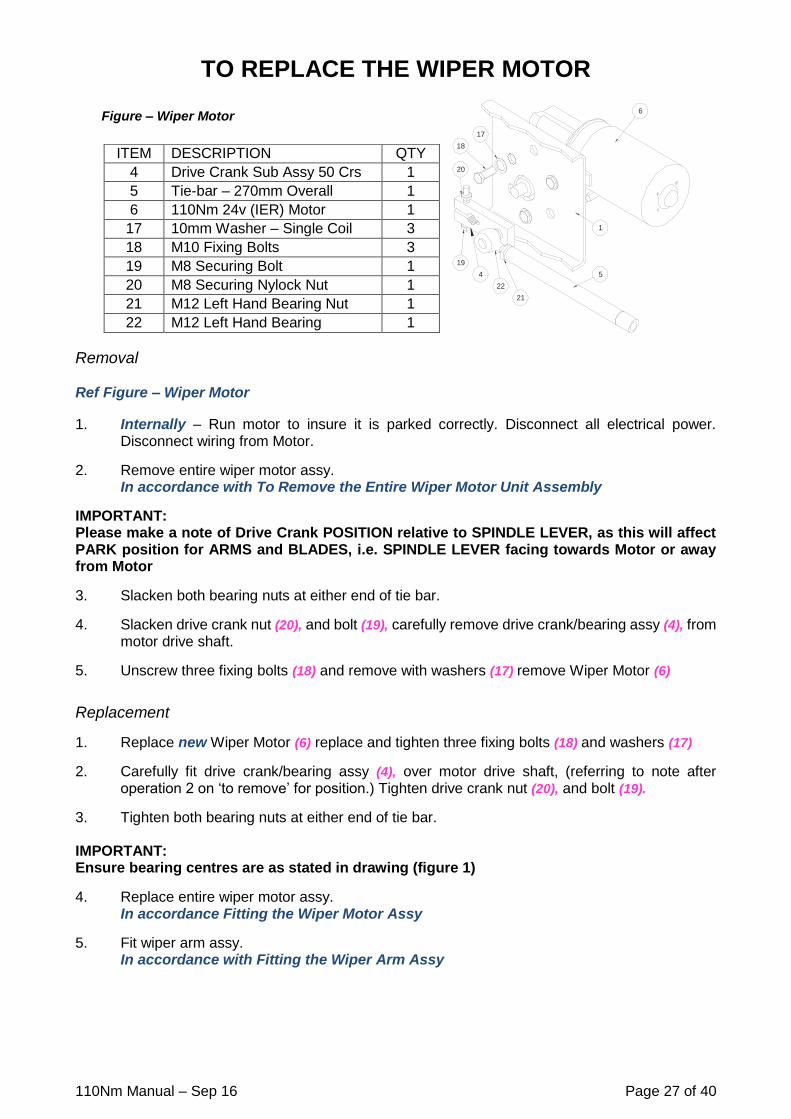
TO REPLACE THE WIPER MOTOR
Removal Ref Figure – Wiper Motor
1. Internally – Run motor to insure it is parked correctly. Disconnect all electrical power. Disconnect wiring from Motor.
2. Remove entire wiper motor assy. In accordance with To Remove the Entire Wiper Motor Unit Assembly
IMPORTANT: Please make a note of Drive Crank POSITION relative to SPINDLE LEVER, as this will affect PARK position for ARMS and BLADES, i.e. SPINDLE LEVER facing towards Motor or away from Motor
3. Slacken both bearing nuts at either end of tie bar.
4. Slacken drive crank nut (20), and bolt (19), carefully remove drive crank/bearing assy (4), from motor drive shaft.
5. Unscrew three fixing bolts (18) and remove with washers (17) remove Wiper Motor (6)
Replacement
1. Replace new Wiper Motor (6) replace and tighten three fixing bolts (18) and washers (17)
2. Carefully fit drive crank/bearing assy (4), over motor drive shaft, (referring to note after operation 2 on ‘to remove’ for position.) Tighten drive crank nut (20), and bolt (19).
3. Tighten both bearing nuts at either end of tie bar. IMPORTANT: Ensure bearing centres are as stated in drawing (figure 1)
4. Replace entire wiper motor assy. In accordance Fitting the Wiper Motor Assy
5. Fit wiper arm assy. In accordance with Fitting the Wiper Arm Assy
ITEM DESCRIPTION QTY
4 Drive Crank Sub Assy 50 Crs 1
5 Tie-bar – 270mm Overall 1
6 110Nm 24v (IER) Motor 1
17 10mm Washer – Single Coil 3
18 M10 Fixing Bolts 3
19 M8 Securing Bolt 1
20 M8 Securing Nylock Nut 1
21 M12 Left Hand Bearing Nut 1
22 M12 Left Hand Bearing 1
18
17
20
6
5
19
4
22
1
21
Figure – Wiper Motor

110Nm Manual – Sep 16 Page 28 of 40
TO REPLACE THE TIE BAR
Removal
Ref Figure – Wiper Motor
1. Internally – Run motor to insure it is parked correctly. Disconnect all electrical power. Disconnect wiring from Motor.
2. Remove entire wiper motor assy. In accordance with To Remove the Entire Wiper Motor Unit Assembly
IMPORTANT: Please make a note of Drive Crank POSITION relative to SPINDLE LEVER, as this will affect PARK position for ARMS and BLADES, i.e. SPINDLE LEVER facing towards Motor or away from Motor
3. Slacken both bearing nuts at either end of tie bar.
4. Slacken drive crank nut (20), and bolt (19), carefully remove drive crank/bearing assy (4), from motor drive shaft.
5. Unscrew tie bar – (5) from drive crank bearing (left hand thread) (22)
6. Repeat operation 5 on liner/lever/bearing assy (right hand thread) and remove tie bar (5),
Replacement
1. Screw new tie bar (note groove is on right hand end of tie bar) onto bearing (right hand thread) at liner/lever/bearing assy.
2. Screw new tie bar on to bearing (left hand thread) (22) of drive crank/bearing assy.
3. Carefully fit drive crank/bearing assy (4), over motor drive shaft, (referring to note after operation 2 on ‘to remove’ for position.) Tighten drive crank nut (20), and bolt (19).
4. Tighten both bearing nuts at either end of tie bar.
IMPORTANT: Ensure bearing centres are as stated in drawing (figure 1)
5. Replace entire wiper motor assy. In accordance with Fitting the Wiper Motor Assy
6. Fit wiper arm assy. In accordance with Fitting the Wiper Arm Assy
ITEM DESCRIPTION QTY
4 Drive Crank Sub Assy 50 Crs 1
5 Tie-bar – 270mm Overall 1
6 110Nm 24v (IER) Motor 1
17 10mm Washer – Single Coil 3
18 M10 Fixing Bolts 3
19 M8 Securing Bolt 1
20 M8 Securing Nylock Nut 1
21 M12 Left Hand Bearing Nut 1
22 M12 Left Hand Bearing 1
18
17
20
6
5
19
4
22
1
21
Figure – Wiper Motor

110Nm Manual – Sep 16 Page 29 of 40
TO REPLACE THE LEVER/LINER/SPINDLE SUB ASSEMBLY
Removal
1. Internally – Run motor to insure it is parked correctly. Disconnect all electrical power. Disconnect wiring from Motor.
2. Remove entire wiper motor assy. In accordance with To Remove the Entire Wiper Motor Unit Assembly
IMPORTANT: Please make a note of Drive Crank POSITION relative to SPINDLE LEVER, as this will affect PARK position for ARMS and BLADES, i.e. SPINDLE LEVER facing towards Motor or away from Motor
3. Slacken both bearing nuts at either end of tie bar.
IMPORTANT: Make a note of the protrusion length of the Liner and/or Spindle from the front of the Bracket (1),
4. Unscrew tie bar from right hand bearing of liner/lever/bearing assy.
5. Unscrew remove entire liner/lever/bearing assy from bracket.
Replacement
1. Screw entire new liner/lever/bearing assy into bracket.
2. Screw tie bar onto right hand bearing at main liner/lever/bearing assy.
3. Tighten both bearing nuts at either end of tie bar.
IMPORTANT: Ensure bearing centres are as stated in drawing (figure 1)
4. Replace entire wiper motor assy. In accordance with Fitting the Wiper Motor Assy
5. Fit wiper arm assy. In accordance with Fitting the Wiper Arm Assy

110Nm Manual – Sep 16 Page 30 of 40
CONTROLLER INSTALLATION INSTRUCTIONS NOTE Retain all items removed in a safe place, as they will be required on reassembly. Any item to be discarded must be done in accordance to vessels manufacturer described task guidelines If you experience any difficulty in the fitting of any of the controller /switches, please do not hesitate to contact Customer Service at B. Hepworth & Co. for advice. Use the drawings for reference.
WARNING: Isolate the electrical supply before commencing any fitting work on any part of the wiper system.

110Nm Manual – Sep 16 Page 31 of 40
12V OR 24V MULTI-SWITCH – WIRING & SIZES
WASHERWIPER
LOW SPEED
HIGH SPEED
ON-SHORT DELAY
PRESS INTERMITTENTVARIABLE
WIPE
ON-LONG DELAY
OFF/PARK
83
68
47
HEPWORTHMARINE INTERNATIONAL
2-4 MERSE ROAD. REDDITCH. B98 9HL. TEL.01527 61243
75 CRS
R5
7.5 60 SQUARE
60 CRS
CONSOLE CUT OUT DETAIL - 90087010 - 1 x 24v Multi-Switch & Plate
- 90087200 - 1 x 12v Multi-Switch & Plate
CONSOLE CUT OUT DETAIL - 10166600 - 1 x 24v Multi-Switch only
- 10167100 - 1 x 12v Multi-Switch only
WIPER
WASHER
56
47
9
12
MOUNTING SLOT DETAIL
56
R8.4
3
4 HOLES Ø4
+vDC
0VDC 0vDC
+vDC
BLACK (18g)
BROWN (18g)
BLUE (18g)
YELLOW (18g)
WHITE (18g)
RED (14g)
LOW SPEED
DELAY
ON-SHORT
ON-LONG DELAY
HIGH SPEED
OFF/PARK
INTERMITTANT
VARIABLE
WIPE
7.5A
-F
BOSCH HARNESS CONNECTOR (REAR VIEW)
SUPPRESSED TO COMMERCIAL
NON-INSULATED
SOLENOID VALVE
WASH PUMP
OR
LEVELS WITHIN DIRECTIVES
(2)
(5)
INSULATED EARTH
31b
53
CONNECTORS
BOSCH
31
53a
31b
53
53b
(4)
(3)
(2)
(5)
(6)
(3)
53a
53b
(6)
BOSCH MOTOR
M
NC
31
(4)
(3)
53a
53b
(2)
31b
53
(6) (5)
NC
31
(4)
CONNECTION DETAILS:
31 - 0vDC SUPPLY
31b - SELF-PARK REVERSAL FEED
53 - SLOW SPEED
53a - SELF-PARK FEED & +VE SUPPLY
53b - FAST SPEED
WIRING DETAIL
(1) (1)
COLE-HERSEE MULTI-FUNCTION
24v SWITCH - 10166600
12v SWITCH - 10167100
WIPER
WASHER
WIPER
WASHER
32
29

110Nm Manual – Sep 16 Page 32 of 40
12V OR 24V MULTI-SWITCH – OPERATION
NOTE For other all other switch or control instructions refer to the ship’s fitters/suppliers manual.
Ref Figure – Multi-Switch
1. Check switch is in off position before starting. (OFF/PARK) IMPORTANT Do not run wipers on a dry screen. 2. To apply washer fluid to screen, press knob. (WIPER WASHER) This will apply washer fluid
for period of time button is pressed. NOTE The wiper will also operate for 3-4 wipes at normal speed after the washer fluid stops. 3. Turn knob CLOCKWISE it will (CLICK) which turns wipers on. Switch is now in area of
variable intermittent wipe cycle time. Which is between (ON-LONG DELAY 15 seconds) and (ON-SHORT DELAY 2 seconds) positions.
4. As knob is turned further clockwise between two positions it shortens delay period between
wipes. 5. Turn knob CLOCKWISE to next (CLICK) (LOW SPEED). This gives a continuous wipe across
screen at a standard speed, with no delay between wipes. 6. Turn knob CLOCKWISE to last (CLICK) (HIGH SPEED). This gives a continuous wipe across
screen at a faster speed, with no delay between wipes. 7. Turn knob ANTI-CLOCKWISE to off position when finished. (OFF/PARK) IMPORTANT When turning to the off position ensure that it CLICKS to confirm fully off
Figure – Multi-Switch
WASHERWIPER
LOW SPEED
HIGH SPEED
ON-SHORT DELAY
PRESS INTERMITTENTVARIABLE
WIPE
ON-LONG DELAY
OFF/PARK
HEPWORTHMARINE INTERNATIONAL
2-4 MERSE ROAD. REDDITCH. B98 9HL. TEL.01527 61243

110Nm Manual – Sep 16 Page 33 of 40
12V/24V ROTARY SWITCH – WIRING & SIZES
OFF/PARK
ON
FAST
HEPWORTH MARINE INTERNATIONAL
WASHER
WIPER30
45
PRESS
WIPER
WASHER
4 HOLE Ø4
35.5 CRS 45
18 CRS
18 CRS
65
1 HOLE Ø42
36 CRS
SELF-PARK FEED (+VE)
0V
SELF-PARK REVERSAL FEED
+VE
PB
LW
H
B
WASHER (+VE)
0V
+VE
53b
53a
31b
LOW SPEED
HIGH SPEED
(4)
(3)
31
(2)
(5) 53
(6)
M
Ø41.2
REAR VIEW
OF SWITCH
WASH PUMP
/ VALVE
MERSE Rd. REDDITCH. B98 9HL. TEL.01527 61243
30
65
Ø41.2WIPER
WASHER
OFF/PARK
SLOW
FAST
BODY
KNOB11.2
9
Ø11.2
CONSOLE CUT OUT DETAIL - 90043000 - 1 x 12/24v Rotary Switch & Plate
CONSOLE CUT OUT DETAIL - 10094800 - 1 x 12/24v Rotary Switch only
WIRING DETAIL
CONNECTION DETAILS:
31 - 0vDC SUPPLY
31b - SELF-PARK REVERSAL FEED
53 - SLOW SPEED
53a - SELF-PARK FEED & +VE SUPPLY
53b - FAST SPEED
BOSCH
CONNECTORS
BOSCH
MOTOR
BOSCH HARNESS CONNECTOR (REAR VIEW)
NON-INSULATED
(2)
(5)
INSULATED EARTH
31b
53
(3)
53a
53b
(6)
NC
31
(4)
(3)
53a
53b
(2)
31b
53
(6) (5)
NC
31
(4)
(1) (1)

110Nm Manual – Sep 16 Page 34 of 40
12V/24V ROTARY SWITCH – OPERATION
NOTE For other all other switch or control instructions refer to the ship’s fitters/suppliers manual.
Ref Figure – Rotary Switch
1. Check switch is in off position before starting. (OFF/PARK) IMPORTANT Do not run wipers on a dry screen. 2. To apply washer fluid to screen, press knob. (WIPER WASHER) This will apply washer fluid
for period of time button is pressed. NOTE It does not activate the wiper 3. Turn knob CLOCKWISE it will (CLICK) which turns wipers on, (ON). This setting gives a
continuous wipe across screen at a standard speed, with no delay between wipes. 4. Turn knob CLOCKWISE to last (CLICK) (FAST). This setting gives a continuous wipe across
screen at a faster speed, with no delay between wipes. 5. Turn knob ANTI-CLOCKWISE to off position when finished. (OFF/PARK)
Figure – Rotary Switch
OFF/PARK
ON
FAST
HEPWORTH MARINE INTERNATIONAL
WASHER
WIPER
PRESS
WIPERWASHER
MERSE Rd. REDDITCH. B98 9HL. TEL.01527 61243

110Nm Manual – Sep 16 Page 35 of 40
12V/24V TOGGLE SWITCH – WIRING & SIZES
CONSOLE CUT OUT DETAIL - 90041400 - 1 x 12/24v Toggle Switch & Plate
CONSOLE CUT OUT DETAIL - 10079200 - 1 x 12/24v Toggle Switch only
19
3842
11
22
21
15
30
42 50
INTERNATIONAL
HEPWORTH MARINE
FAST
OFF/PARK
SLOW SLOW
30
38
WIPER SWITCH
18 13
4 HOLES Ø2 TO
SUIT M3 SELF-TAP 4 HOLES Ø3
4 HOLES Ø5
53
(4)
53b
(2)
53a
(6)31b
(8)
1 HOLE Ø12.0 THRU.18 1318
34
OFF/PARK
SLOW
FAST
53
(4)
53b
(2)
53a
(6)31b
(8)
FUSE (NOT SUPPLIED)
31
53a5331b 53b
M
SLOW FAST
SHOWN IN OFF/PARK CONFIGURATION
31b
53 53b
53a
(+ve)
& SELF
PARK
FEED
SELF
PARK
REVERSAL
FEED
+ve DC
SUPPLY
(8)
(4)
(6)
(2)
310v DC
SUPPLY
SWITCH CONTACTSPOSITION
OFF/PARK
SLOW SPEED
FAST SPEED
8 4 6 2
WIRING DETAIL
SUPPLY
TOP
`CH` MARK
(2)
(4)
(8)
(6)
VIA CONNECTOR SOCKET
4563 2 1
24v DC (+VE)
(-VE)0v DC
SUPPLY
12v or 24v DC (+VE)
SUPPLY
BOSCH
CONNECTOR
53b
53b
53a
53a
31b
31b
53
53
31
31
BOSCH HARNESS CONNECTOR (REAR VIEW)
NON-INSULATED
(2)
(5)
INSULATED EARTH
31b
53
(3)
53a
53b
(6)
NC
31
(4)
(3)
53a
53b
(2)
31b
53
(6) (5)
NC
31
(4)
(1) (1)
CONNECTION DETAILS:
31 - 0vDC SUPPLY
31b - SELF-PARK REVERSAL FEED
53 - SLOW SPEED
53a - SELF-PARK FEED & +VE SUPPLY
53b - FAST SPEED

110Nm Manual – Sep 16 Page 36 of 40
12V/24V TOGGLE SWITCH – OPERATION
NOTE For other all other switch or control instructions refer to the ship’s fitters/suppliers manual.
Ref Figure – Toggle Switch
1. Check switch is in off position before starting. (OFF/PARK) IMPORTANT Do not run wipers on a dry screen. 2. This switch does not control application of washer fluid. 3. Pushing toggle to centre position (SLOW) gives a continuous wipe across screen at a
standard speed, with no delay between wipes. 4. Pushing toggle to bottom position (FAST) gives a continuous wipe across screen at a faster
speed, with no delay between wipes. 5. Push toggle to top position when finished. (OFF/PARK)
Figure – Toggle Switch
INTERNATIONAL
HEPWORTH MARINE
FAST
OFF/PARK
SLOW SLOW
WIPER SWITCH

110Nm Manual – Sep 16 Page 37 of 40
EXTERNAL FITTINGS – ARMS Fittings for Arm and Blade
4
3b
44
3a
5
6a
67
20mm14mm
Part No. Description Qty
80205600 Blade Retaining Screw (14mm Blade Clip) (3) 1 per Arm
80010700 Blade Retaining Screw (20mm Blade Clip) (3) 1 per Arm
10011400 M4 Nylock Nut (4) 1 per Arm
80005100 Heavy Duty Head – Weather Cap (5) 1 per Arm
80200100 Wash Jet Assy (6) 1 per Arm
80201700 Wash Jet Bracket (6a) 1 per Arm
80200400 Wash Hose – 4mm I/D x 6Mmm O/D (7) Metres
Part No. Description
60680600 Arm Extractor Tool – All Head Types As Required
50 CRS

110Nm Manual – Sep 16 Page 38 of 40
EXTERNAL FITTINGS – LINKAGE
Fittings for M26 Liners and 16mm Spindles protruding outside the Bulkhead
Part No. Description Qty
60250300 Idler Gasket (7) 1 per Unit
60250200 Idler Plate (8) 1 per Unit
10029100 26mm Washer – Neoprene (9) 1 per Liner
10026100 26mm Washer – Flat (10) 1 per Liner
10026600 26mm Washer – Single Coil (11) 1 per Liner
10015300 M26 Hex Nut (12) 1 per Liner
60054600 26mm Weather Cap (13) 1 per Liner
10027800 10mm Washer – Flat (14) 1 per Liner
10018000 M10 Hex. Nut (15) 1 per Liner
10063500 10mm Nut Cap (16) 1 per Liner
8
7
9
11
13
10
12
14
16
15

110Nm Manual – Sep 16 Page 39 of 40
THIS PAGE INTENTIONALLY LEFT BLANK

110Nm Manual – Sep 16 Page 40 of 40
2-4 MERSE ROAD NORTH MOONS MOAT REDDITCH WORCESTERSHIRE B98 9HL ENGLAND
TEL: +44(0)1527 61243 OR 67701 FAX: +44(0)1527 66836
Email: [email protected] WEBSITE: www.b-hepworth.com