Embed Size (px)
Citation preview

Technical information

8
CERTIfICATION ACCORDING TO EN ISO 9001 : 2008The PCE quality management system has been certified according to the standard DIN EN ISO 9001 : 2008!
CE-MARKING - LOW VOLTAGE GuIDELINEPurpose:• mainly a symbol for free trade in the European Community, • if a product has been traded legally in one of the member countries, it can be traded legally in the whole Community,• no quality mark or grade labelling,• no sign of conformity to standards; to a certain extent a safety mark, because it indicates the compliance to the fundamental safety requirements.
The guidelines determine only basic requirements the products have to meet.
The essential points for the CE-identification are:• it is obligatory for the producer or the EEC importer to put on the CE-identification label,• the producer, EEC-importer must hold the engineering data for the disposal of the authorities.• standard marks of conformity are permissible besides the CE-identification - but no longer necessary.
APPROVALS - THE quALITy MARKS
There has been created a CCA-method (CENELEC Certification Agreement) for mutual recognition of national approvals. PCE has tested all important products according to this method. An outline of certificates obtained is listed below for refe-rence:
CEE and IECThe term "CEE" generally refers to Industrial Plugs and Sockets that comply with International Standard IEC 60309. CEE is the abbreviation of "International Commission on rules for the approval of Electrical Equipment".
CONfORMITy TO STANDARDSCEE plugs and sockets are internationally normalized by IEC 60309-1 and IEC 60309-2 equivalent to the European Norms EN 60309 part 1 and EN 60309 part 2.
IEC is the "International Electrotechnical Commission" - which is the world organization for international standardization of electrical equipment.
Information

9
CENELEC
European Committee for Electrotechnical Normalization - members are the national electrotechnical committees from Austria, Belgium, Bulgaria, Czech Republic, Croatia, Denmark, Germany, Esonia, Finland, France, Greece, Hungary, Ireland, Iceland, Italy, Latvia, Lithuania, Luxemburg, Malta, Netherlands, Norway, Poland, Portugal, Rumania, Slovakia, Sweden, Switzerland, Spain and the United Kingdom.
SySTEM
The standard CEE plugs and sockets according to EN 60309 respectively IEC 60309 are designed in their main dimensi-ons in a way that plugs and sockets with the same rated currents, nominal working voltage ranges, the same number of poles and frequency of different producers are compatible.
In order to prevent the insertion of plugs and sockets of different voltages and frequencies, 12 positions of the earthing contact are assigned to the polarizing slot of the skirt of a socket.
The number with the following letter „h“ indicates the position of the earth contact tube, comparing the frontside of the socket or connector with the face of a clock. The keyway is situated at 6 o'clock (see page 11).
ROHS — DIRECTIVE 2002/95/EG
We declare that our distribution boxes and industrial plugs and sockets as direct use, do not have to comply to RoHS directive 2002/95/EG.
For our industrial plugs and sockets (including CEE) used and or mounted into products that belong to categories 1-8 they have to comply to RoHS directive. We want to confirm that PC Electric meets all requirments of RoHS directive.
Affective Products of RoHS directive: Large household appliances, small household appliances, IT and telecommuni-cations equipment, consumer equipment, lighting, electrical and electronic tools (except large scale stationary industrial tools), toys, leisure and sports equipment and automatic dispensers.
PILOT CONTACT
The pilot contact for levels of current from 63A to 125A is an auxiliary contact – with delayed close when inserted and lea-ding open when pulled – and is used as an electrical interlock. An interlock prevents inserting and pulling under load. CEE couplings and socket-outlets with pilot contact have longer phase contacts and do not guarantee safety from finger-touch. This must be done by an interlock.
As PCE CEE plugs and sockets have sufficient switching capacity, the CEE couplings and socket-outlets are supplied as standard without a pilot contact and shorter phase contact with protection from finger-touch.
Technical data:
Kind of connection: Screw terminals
wire flexible [mm2] 1 - 2,5
solid [mm2] 1 - 4
Contact screws [Ncm] 100 Ncm
2A

10
EP
EP
N
N
1F-
1K-
2L 3L
tcatnoC-toliPhctiwS hctiwS
1L
Pilot
N
N
3L2L1L
3LEP 2L1L
EP
EP
N
N
1F-
1K-
3L1L 2L
2L 3L1L
3L1LEP Pilot
N
2LN
Pilot
PCS (PILOT CONTACT SySTEM):The PCS is a built-in auxiliary contact, used only for 63A and 125A connectors and socket-outlets, for protective electrical interlocking or for additional con-trol purposes, with isolated connection in the socket-outlet. CEE connectors and sockets have longer phase contacts and guarantee no finger protection; this must be fulfilled by a locking.
The PCS provides the following advantages:• no special cable required for the plug• isolated inserting and pulling
Technical Datas:• contacts: silver-coated• wires: 2x YF 1.5qmm 450mm
Plug Plug
Standard locking mechanism PCS locking mechanism
Rated current wire flexible[mm2]
wire fixed (single or
stranded) [mm2]
P-Nova and P-Nova Plus socket 1 - 2x2,5 1 - 2x2,5
Taurus and TopTaurus plug 0,75-2,5
Taurus and TopTaurus connector 1-2,5
Taurus 3-way connector 1-2,5
Connection cross-section for PCE-products
Rated current
wire flexible[mm2]
wire fixed (single or
stranded) [mm2]
16A 1-2,5 1-4
32A 2,5-6 2,5-10
63A 6-16 6-25
125A 16-50 16-70
Rated current Dismantling length[mm]
Stripping length [mm]
16A 50 10-12
32A 50 12-14
63A 100 12-18
125A 100 18-20
Taurus and Top Taurus 30 7
P-Nova 10
P-Nova (screwless) 8-14
P-Nova Plus 8-10
DISMANTLING AND STRIPPING LENGHTRecommended datas for PCE products
TERMINALSPCE – connection terminals are laid out for the following cross-sections:
Information

11
L2 L3
L1 N
PE
L2
L3
L1
N
PE
230V50+60Hz
230V50+60Hz
230V50+60Hz
POSITION Of THE EARTHING CONTACT ACC. TO IEC 60309-2 – SERIE I
COLOuR CODES
For ease of identification of the various voltages and frequencies all CEE plugs and sockets are colour coded:
Rated operatingvoltage:
Colour code:
20-25V violet40-50V white100-130V yellow200-250V blue380-480V red500-690V black > 60-500Hz greenno colour code grey
9h6h
* non standard** non standard for 63A, 125A
Position of the earthing contact.View: frontside socket or connector
INTERNATIONAL RATING – SERIE Ifor appliances >50V - details see table above
Voltage Frequency 2P+E 3P+E 3P+N+EV Hz 16+32A 63+125A 16+32A 63+125A 16+32A 63+125A
57/100 to 75/130 50 and 60 4 4100 to 130 50 and 60 4 4 4 4
120/208 to 144/250 50 and 60 9 9200 to 250 50 and 60 6 6 9 9
200/346 to 240/415 50 and 60 6 6220/380250/440
5060 3 3
250/440 to 265/460 60 11 11277/480 to 288/500 50 and 60 7 7347/600 to 400/690 50 and 60 5 5
380 to 415 50 and 60 9 9 6 6380440
5060 3 3
440 to 460 60 11 11480 to 500 50 and 60 7 7 7 7600 to 690 50 and 60 5 5
> 50 100 to 300 10 10 10 10 10 10> 50 >300 to 500 2 2 2 2 2 2
> 50 to 250 DC 3 3> 250 DC 8 8
supply by isolatingtransformer 50 and 60 12 12 12 12 12 12
Others 1 1 1 1 1 1
3P+N+E
3P+E
2P+Esupply from an isolating trans-former
supply from an isolating trans-former
supply from an isolating
transformer
121110
9
87 6 5
4
3
21
h
>250Vdirect current
to 250Vdirect
current
460V60Hz
460V60Hz
100-300Hz
100-300Hz
100-300Hz
400V50+60Hz
500V50+60Hz
500V50+60Hz
500V50+60Hz
690V50+60Hz
690V50+60Hz
400V50+60Hz
400V50+60Hz
110V50+60Hz
110V50+60Hz
110V50+60Hz
380V50Hz,440V60Hz
380V50Hz,440V60Hz
300-500Hz
300-500Hz
300-500Hz
othe
r nom
inal
vol
tage
s an
d/or
frequ
encie
s

12
E1 L2 L3 T V16 3 29-31 ≥75 40-41 ≥4 ≥816 4 33-35 ≥80 46-47 ≥5 ≥816 5 37-39 ≥90 52-53 ≥7 ≥8
32 3 39-41 ≥90 53-54 ≥7 ≥832 4 39-41 ≥90 53-54 ≥7 ≥832 5 44-46 ≥105 59-60 ≥8 ≥9
1st digit Protection against ingress 2nd digit Protection against penetration of water of solid objects 2 ø 12,5 mm 0 non protection 3 ø 2,5 mm 3 spraying water at an angle up to 60° from the vertical 4 ø 1 mm 4 splashing water from any direction 5 dustproof 5 water jets from any direction 6 dust-tight 6 strong water jets from any direction 7 temporary immersion in water
8 continuous submersion in water
Example: IP44 = 1st digit = 4 . protection against solid objects larger than 1mm ø 2nd digit = . 4 protection against splashing water from any direction
LOCKING DEVICEA locking device prevents unintended withdrawal by locking the hinged lid in a lug/cavity or a bayonet system with a bayonet ring. According to EN 60309 the following locking devices have to be provided:
Exstract from the standard EN60309 for plugs and flanged plugs
IP (INGRESS PROTECTION) - RATINGSCEE-plugs and sockets with rated currents 16A and 32A must meet the system of protection IP44 or IP67; 63A and 125A protection degree IP66/67 according to EN 60529.
The degree of protection is tested: - on sockets and connectors, with and without inserted plug or appliance plug- on plugs and appliance plugs, when fully inserted into the socket or connector.
Locking device (nose)
Locking device9 min.
Positioning table (in mm):
rated current protection degree sockets and connectors plugs and appliance plugs
16A and 32A IP44 hinged lid lug/cavity
16A and 32A IP67 bayonet system lug/cavity and bayonet ring
63A and 125A IP67 bayonet system bayonet ring
Information

13
IK-Code IK01 IK02 IK03 IK04 IK05 IK06 IK07 IK08 IK09 IK10
Load energy in joule 0,14 0,2 0,35 0,5 0,7 1 2 5 10 20
IK-CODE:The IK code is a coding system according to ICE/EN 50102, which defines the degree of protection provided by an enclosure against damaging mechanical loads. Each characteristic numerical group of the IK Code represents a load energy value as per the table:
Chemicals Concentration Resistance
PA6 PC/ABSacetone + -aldeyhde o -alcohols + +formic acid 4-5% - oamine + -ammonia 5% + o / -ammonium chloride 35% + -inorganic salts + obenzine + +benzol + ochlorine o oacetic acid 5% o +ester + oethyl aether + ofats + +hydrofluoric acid - oformaldehyde 5% + -formalin 3-4% + -glycol o o
Chemicals Concentration Resistance
PA6 PC/ABSglycerin + ocalcium hydroxide 50% o -ketone + -fuels + omethane + xpetroleums + +sodium chloride + +sodium hydroxide 10% + xsodium hydroxide 2-8% + -nitrobenzene + -oils + +phosphoric acid 10% - opropanol + onitric acid 2% - +hydrochloric acid 2% - osulfuric acid 50% - +water + +hydrogen peroxide 30% o +
citric acid 20% o +
PLASTIC MATERIALOur plugs and sockets are produced from POLyAMIDE 6. The main characteristics of this material are:
+ resistant o conditionally resistant - not resistant x not specified The information about the resistance is valid with ambient temperature and can lead in coincidence of different medi-as to different resistances. Source: Saechtling Kunststoff pocket book; Carl Hanser Verlag Munich, Vienna and DSM Engineering plastics
• excellent impact resistance combined with high rigidity and solidity,• high thermal stability (self-extinguishing),• very good insulating qualities, • high disruptive strength, • high abrasion resistance,
• high weathering resistance, • very good chemical resistance to various chemicals, • free from cadmium and halogen (fluorine, chlorine, bromine, jodine, astatine)• conform to RoHS-directiv 2011/65/EU (page 9)
PCE - overview chemical resistance:

14
CONTACTS
The contacts are made of a copper-zinc alloy. The most important features are:• high electric conducting capacity 15m/(Ohm mm2);• high resistance to extension up to 103 kN/mm2);• high corrosion resistance in areas of: industrial atmosphere, agriculture , . . . • with nickel-plated contacts increased corrosion resistance in areas of: seawater, steam, sulphur hydrides, agriculture, dairies.• conform to RoHS-directiv 2002/95/EG (page 9)• PCE sockets 63A and 125A have a CuBe lamellar spring for a well contacting and anti-corrosion contacts (page 17).
TEMPERATuRES
IEC/EN 60309 applies to CEE plugs and sockets which are used at an ambient temperature that does not normally exceed the range from -25°C to +40°C. PCE CEE plugs and sockets themselves have an operating temperature of -25°C to +80°C (100°C for 1 hour). The temperature of the contacts is allowed to rise by 50°C under the test conditions set out in Table 8.
Table 8 Cross section of the conductors
Operating current Test duration Test current Plugs, and connectors Sockets A h A mm2 mm2
16 1 22 2,51) 41)
32 1 42 61) 10
63 2 63 16 25
125 2 125 50 70
1) The values are increased to 10mm2 for plugs and sockets with up to 50V rated operating current.
TORquES fOR PCE PRODuCTS
Rated current Series Torques [Ncm]
16A
Cable gland 400
Housing screws 110
Connecting screws 180
Cable gland >50V 600
Information

15
Rated current Series Torques [Ncm]
32A
Cable gland 500
Housing screws 110
Connecting screws 180
Cable gland >50V 600
63A
Cable gland 1300
Connecting screws 200
Housing screws 200
Connecting screws 200
125A
Cable gland 1400
Connecting screws 200
Housing screws 200
Connecting screws 200
16
LET´S TAKE TWIST - IT´S EASY QUICK AND SAVE
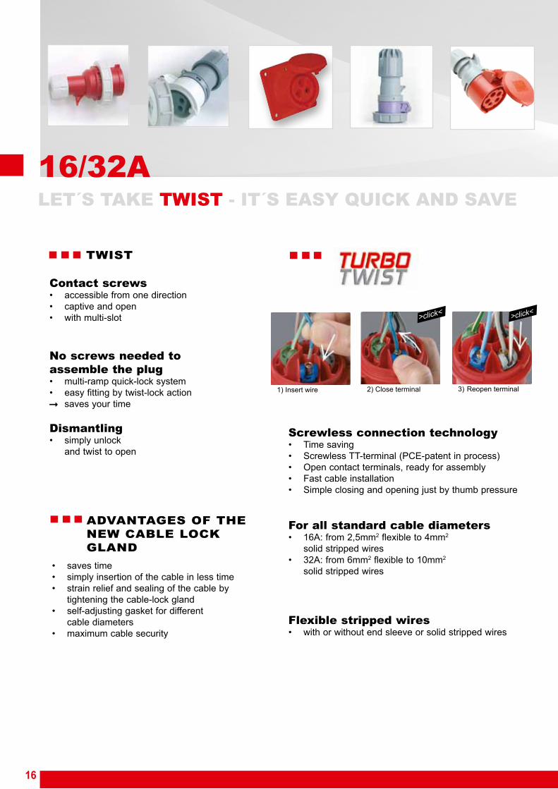
>click< >click<
16/32A
• saves time• simply insertion of the cable in less time• strain relief and sealing of the cable by tightening the cable-lock gland• self-adjusting gasket for different cable diameters• maximum cable security
ADVANTAGES OF THE NEW CABLE LOCK GLAND
TWIST
Contact screws• accessible from one direction• captive and open• with multi-slot
No screws needed to assemble the plug• multi-ramp quick-lock system• easy fitting by twist-lock action
saves your time
Dismantling• simply unlock and twist to open
Screwless connection technology• Time saving• Screwless TT-terminal (PCE-patent in process)• Open contact terminals, ready for assembly• Fast cable installation• Simple closing and opening just by thumb pressure
For all standard cable diameters• 16A: from 2,5mm2 flexible to 4mm2 solid stripped wires• 32A: from 6mm2 flexible to 10mm2 solid stripped wires
Flexible stripped wires• with or without end sleeve or solid stripped wires
1) Insert wire 2) Close terminal 3) Reopen terminal

17
63/125A
P O W E R
TWIST
SAFETY HEAVY DUTY TIME SAVING
Lamellar spring• low insertion and extraction forces• minimum contact resistance• self-cleaning• optimum contact - at least 10 contact points
TWIST-cable gland• secures the cable firmly in position• protects from water and dust• Safety screw locks the screw cap in position
SAFETY
For extreme environments
Exceptional high impact resistance
Extreme heat resistant contact carriers
Anti-corrosion contacts• offer protection in aggressive atmospheres, e.g. in chemical plants, food industries
HEAVY DUTY
TWIST-cable gland
Optimum grip
Wide connection space• fast cable installation
Open contact terminals,
ready for assembly
TIME SAVING
PC Electric GesmbH
Diesseits 145
4973 St. Martin im Innkreis
AUSTRIA
TEL +43 7751 61220
FAX +43 7751 6969