Embed Size (px)
Citation preview
© 2007 Microchip Technology Incorporated. All Rights Reserved. 11084 FOC Slide 1
11084 FOC
Sensorless FOC for PMSM with dsPIC® DSC
© 2007 Microchip Technology Incorporated. All Rights Reserved. 11084 FOC Slide 2
Class ObjectivesWhen you finish this class, you will:
− Understand some of the latest motor control design solutions available
− Be aware of a new algorithm for sensorless Field Oriented Control (FOC) of Permanent Magnet Synchronous Motors (PMSMs)
− Know where to find more information on this algorithm
© 2007 Microchip Technology Incorporated. All Rights Reserved. 11084 FOC Slide 3
Agenda
PMSM OverviewHands-On ExerciseFOC for PMSM controlHands-On ExercisesSensorless techniquesHands-On ExerciseWrap up, Q&A
© 2007 Microchip Technology Incorporated. All Rights Reserved. 11084 FOC Slide 4
Hands-On Exercises
LAB Sessions:− Lab 1 – Running Sensorless Demo− Lab 2 – Enabling Graphs Using DMCI− Lab 3 – Tuning PI Parameters− Lab 4 – Tuning Sensorless Parameters
© 2007 Microchip Technology Incorporated. All Rights Reserved. 11084 FOC Slide 5
Agenda
PMSM Overview− PMSM Applications− PMSM v BLDC− PMSM Construction− PMSM Characteristics− PMSM Operation

© 2007 Microchip Technology Incorporated. All Rights Reserved. 11084 FOC Slide 6
PMSM ApplicationsHigh Efficiency & ReliabilityDesigned for high-performance Servo ApplicationsRuns with/without Position EncodersMore compact, efficient and lighter than ACIMCoupled with FOC control produces optimal torqueSmooth low and high speed performanceLow Audible Noise & EMI
© 2007 Microchip Technology Incorporated. All Rights Reserved. 11084 FOC Slide 7
PMSM Applications
Air Conditioner & Refrigerator (AC) compressorsDirect-drive washing machinesPrecision Machining ToolsAutomotive Electrical power steeringTraction controlData Storage
© 2007 Microchip Technology Incorporated. All Rights Reserved. 11084 FOC Slide 8
PMSM v BLDCHistory…. the motors originated from different areas The fundamentals of Torque production are identicalBLDC is a variant of the PM BDCPMSM describes a AC synchronous motor whose field excitation is provided by PMsControl Methods are different (Six Step v FOC)
© 2007 Microchip Technology Incorporated. All Rights Reserved. 11084 FOC Slide 9
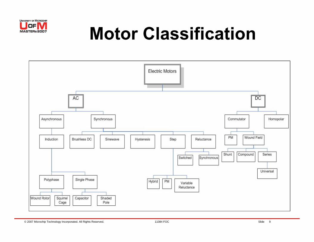
Motor Classification
© 2007 Microchip Technology Incorporated. All Rights Reserved. 11084 FOC Slide 10
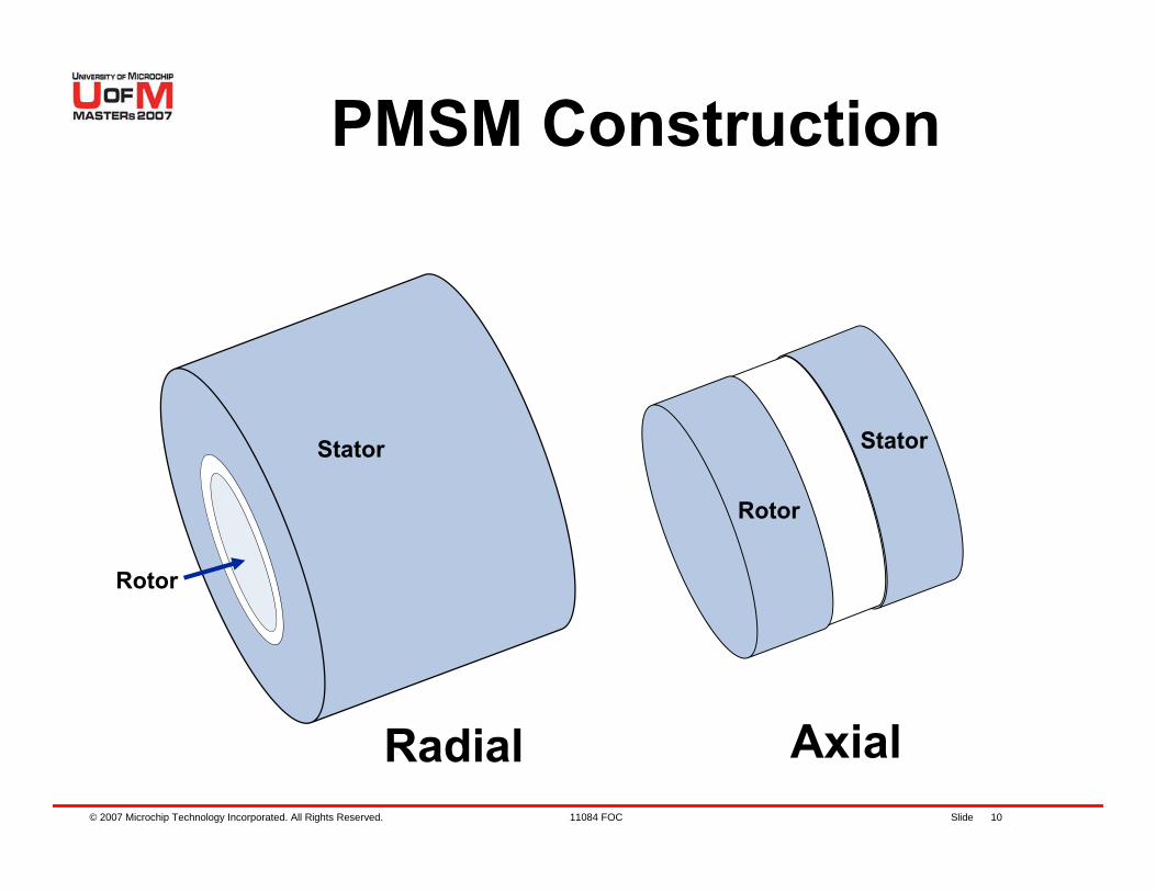
PMSM Construction
Radial Axial
Rotor
Rotor
StatorStator
© 2007 Microchip Technology Incorporated. All Rights Reserved. 11084 FOC Slide 11
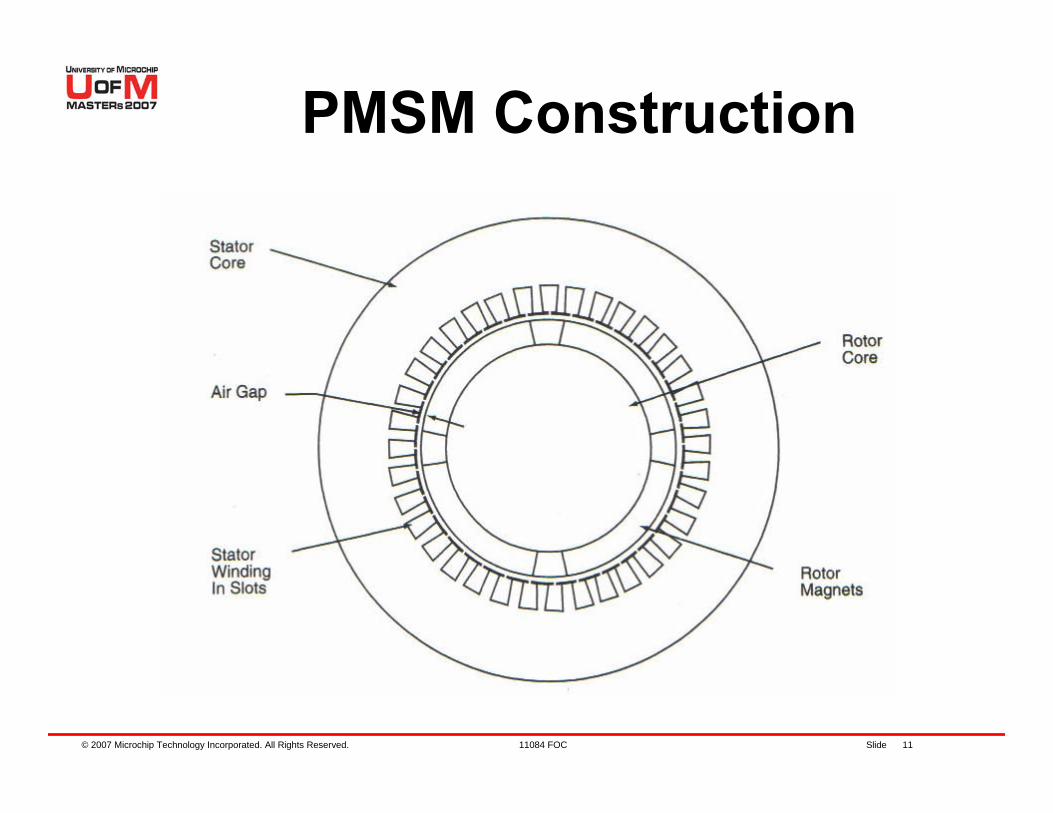
PMSM Construction
© 2007 Microchip Technology Incorporated. All Rights Reserved. 11084 FOC Slide 12
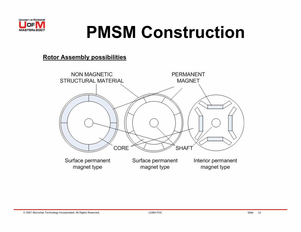
PMSM ConstructionRotor Assembly possibilities
© 2007 Microchip Technology Incorporated. All Rights Reserved. 11084 FOC Slide 13
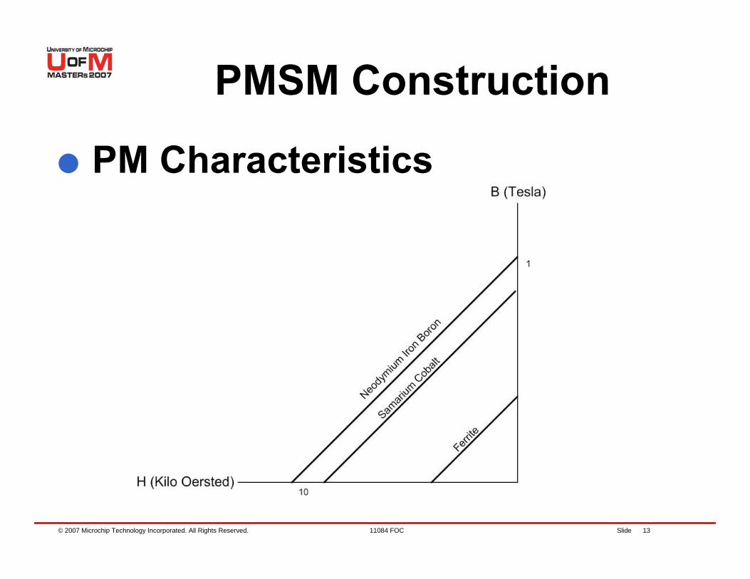
PMSM Construction
PM Characteristics
© 2007 Microchip Technology Incorporated. All Rights Reserved. 11084 FOC Slide 14
PMSM Construction
The PMSM is similar to the BLDC but the Back EMF signals are sinusoidal and trapezoidal respectivelyMathematical treatment is differentDesigned to be driven with a sine waveLike a 3-phase ACIM but air gap flux is produced by rotor mounted magnets
© 2007 Microchip Technology Incorporated. All Rights Reserved. 11084 FOC Slide 15
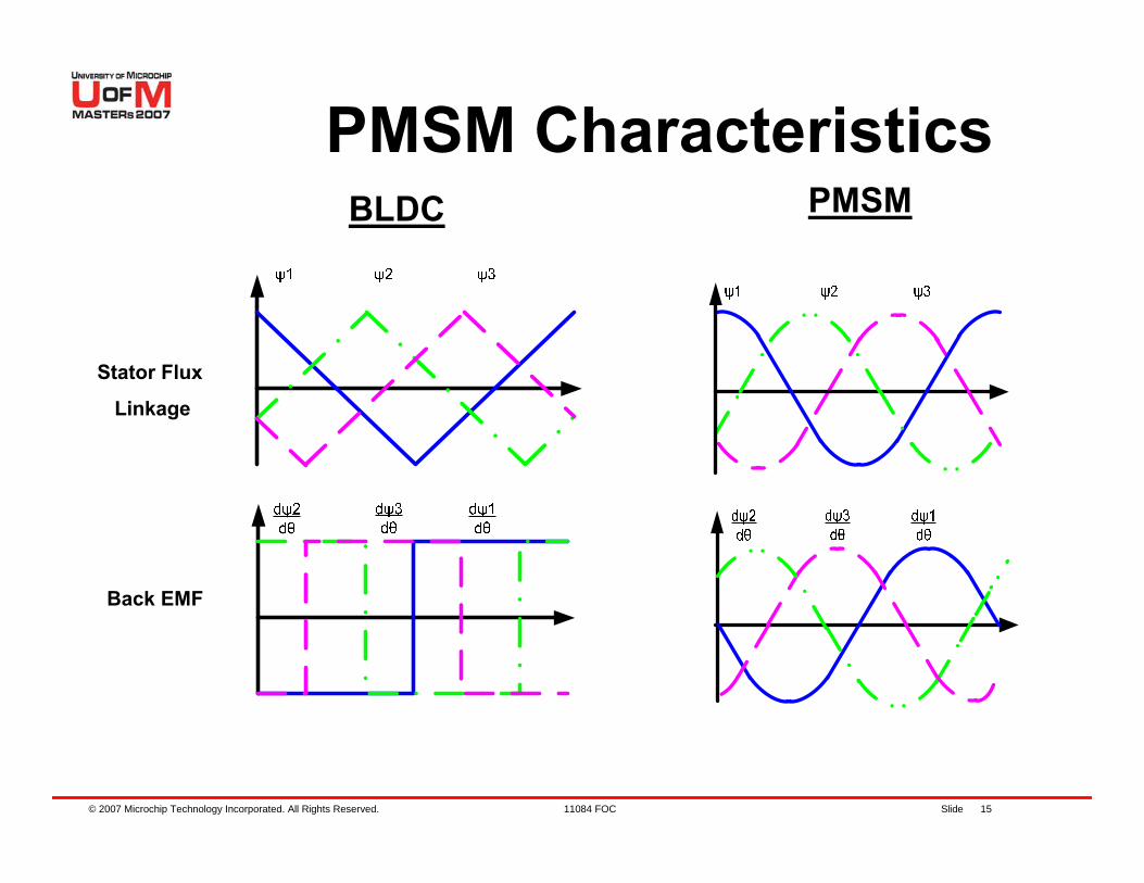
BLDC
PMSM CharacteristicsPMSM
Stator Flux
Linkage
Back EMF
© 2007 Microchip Technology Incorporated. All Rights Reserved. 11084 FOC Slide 16
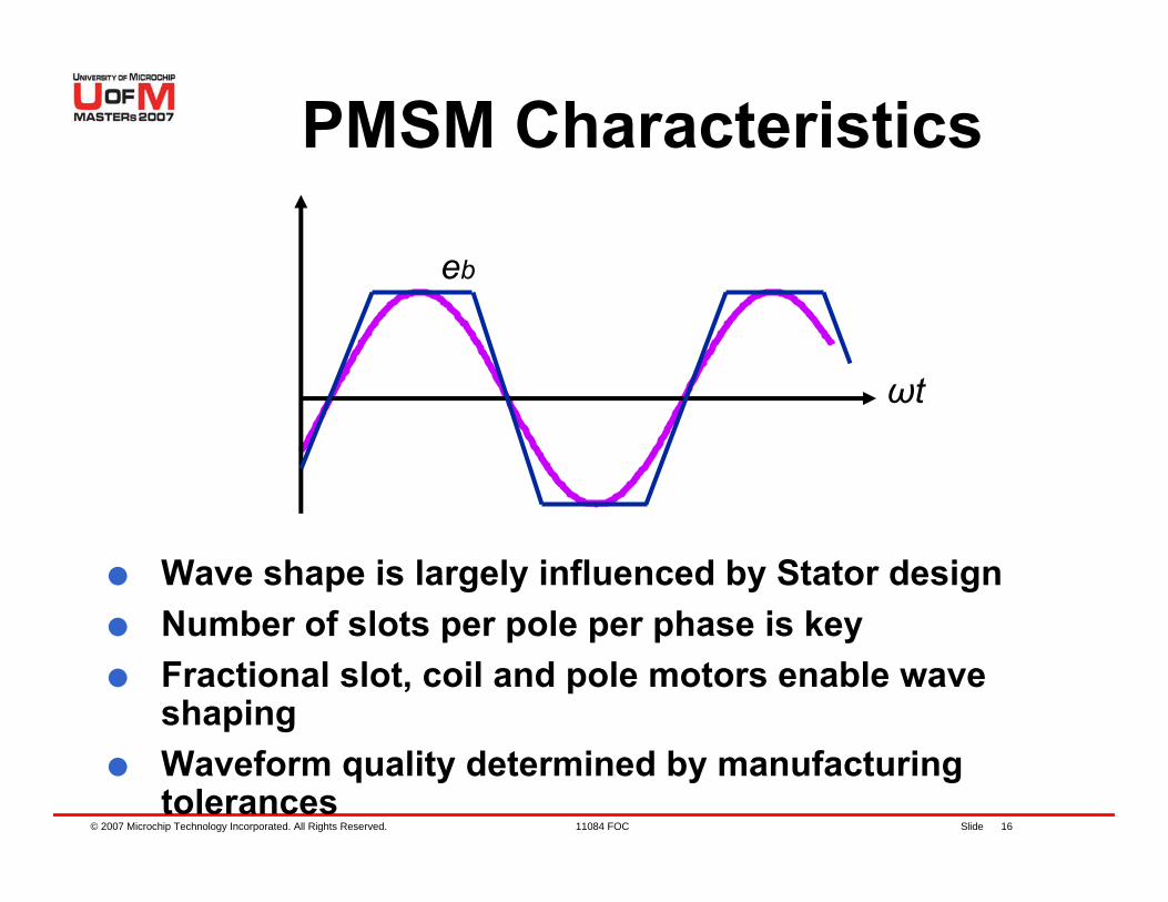
PMSM Characteristics
Wave shape is largely influenced by Stator designNumber of slots per pole per phase is keyFractional slot, coil and pole motors enable wave shapingWaveform quality determined by manufacturing tolerances
eb
ωt
© 2007 Microchip Technology Incorporated. All Rights Reserved. 11084 FOC Slide 17
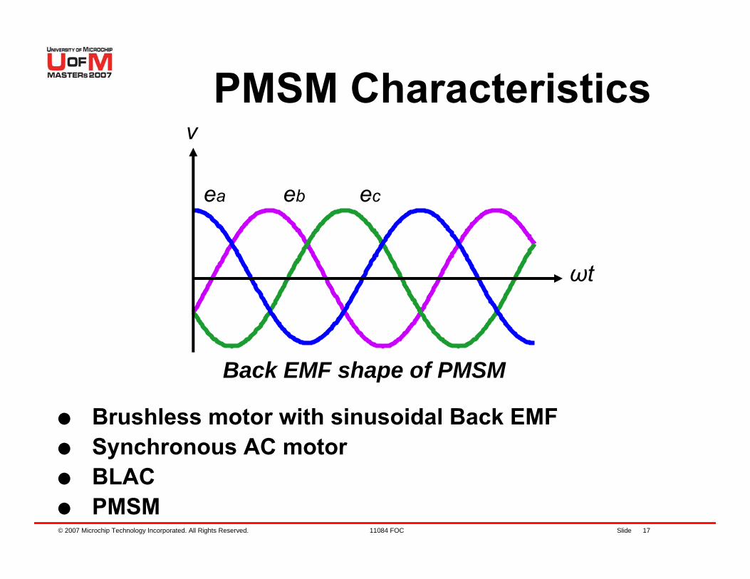
PMSM Characteristics
Brushless motor with sinusoidal Back EMFSynchronous AC motorBLACPMSM
ea eb ec
ωt
Back EMF shape of PMSM
v
© 2007 Microchip Technology Incorporated. All Rights Reserved. 11084 FOC Slide 18
PMSM Characteristics
The Back EMF ideally contains no harmonicsLeads to a reduction in audible noise And better efficiency – reduction of parasitic energy that excites mechanical components in an uncontrolled way
© 2007 Microchip Technology Incorporated. All Rights Reserved. 11084 FOC Slide 19
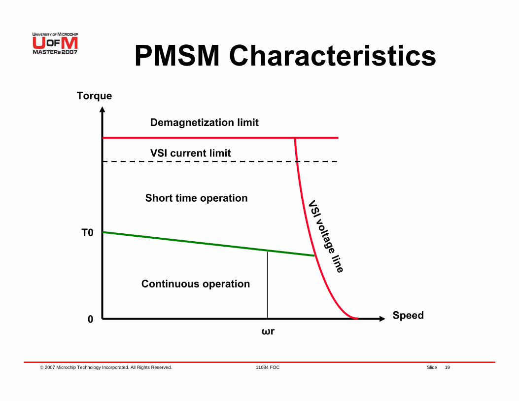
PMSM CharacteristicsTorque
Speed0
Continuous operation
Short time operation VSI voltage line
Demagnetization limit
VSI current limit
ωr
T0
© 2007 Microchip Technology Incorporated. All Rights Reserved. 11084 FOC Slide 20
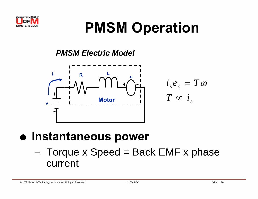
PMSM Operation
s
ss
iTTei
∝= ω
e
Motor
R L
v
i
PMSM Electric Model
Instantaneous power− Torque x Speed = Back EMF x phase
current
© 2007 Microchip Technology Incorporated. All Rights Reserved. 11084 FOC Slide 21
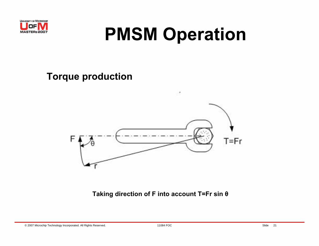
PMSM Operation
Torque production
Taking direction of F into account T=Fr sin θ
© 2007 Microchip Technology Incorporated. All Rights Reserved. 11084 FOC Slide 22
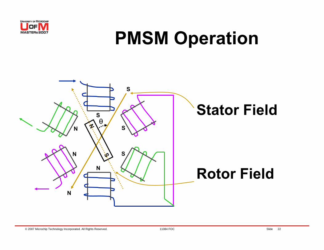
Stator Field
Rotor Field
PMSM Operation
S
N
S
N
N
S
N
S
θ
S
N
© 2007 Microchip Technology Incorporated. All Rights Reserved. 11084 FOC Slide 23
PMSM OperationStator field can be decomposed into components which are parallel and orthogonal to the rotor fieldOnly the orthogonal (quadrature) field produces torqueThe parallel (direct) field produces force which compresses the bearingsPhase current produces stator field and can be measured
© 2007 Microchip Technology Incorporated. All Rights Reserved. 11084 FOC Slide 24
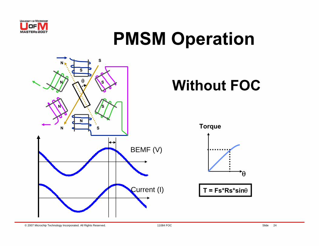
BEMF (V)
Current (I)
Torque
θ
T = Fs*Rs*sinθ
S
N
N
S
θ
S
N
N
S
N
S
Without FOC
PMSM Operation
© 2007 Microchip Technology Incorporated. All Rights Reserved. 11084 FOC Slide 25
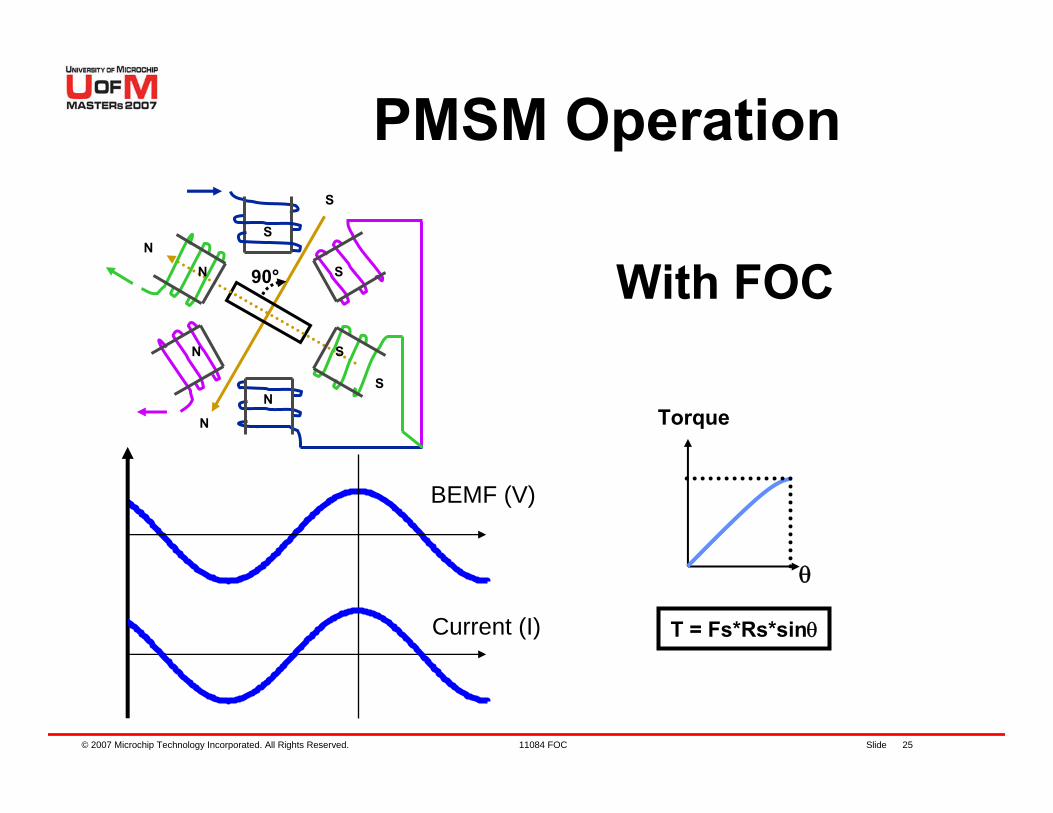
PMSM Operation
BEMF (V)
Current (I)
With FOC
Torque
θ
T = Fs*Rs*sinθ
S
N
N
S
90°
S
N
NS
NS
© 2007 Microchip Technology Incorporated. All Rights Reserved. 11084 FOC Slide 26
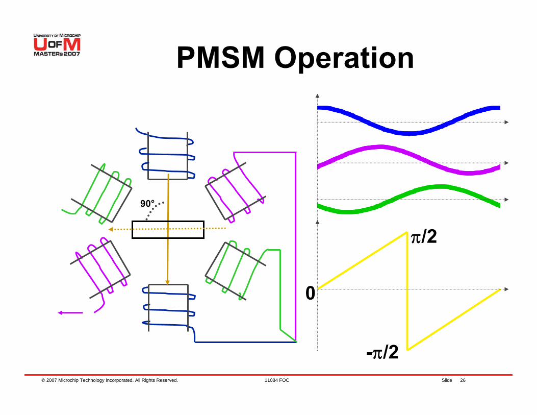
PMSM Operation
90°
0
π/2
-π/2
© 2007 Microchip Technology Incorporated. All Rights Reserved. 11084 FOC Slide 27
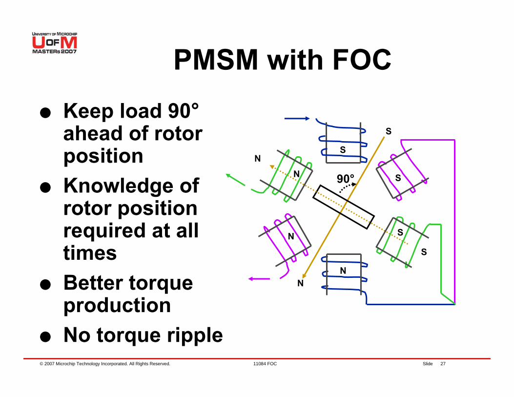
PMSM with FOCKeep load 90°ahead of rotor positionKnowledge of rotor position required at all timesBetter torque productionNo torque ripple
S
N
N
S
90°
S
N
N
S
NS

© 2007 Microchip Technology Incorporated. All Rights Reserved. 11084 FOC Slide 28
Agenda
PMSM OverviewHands-On ExerciseFOC for PMSM controlHands-On ExercisesSensorless techniquesHands-On ExerciseWrap up, Q&A
© 2007 Microchip Technology Incorporated. All Rights Reserved. 11084 FOC Slide 29
Lab 1. Running Sensorless Demo
© 2007 Microchip Technology Incorporated. All Rights Reserved. 11084 FOC Slide 30
Objectives of Lab 1Getting to know the hardware in front of youWhere are the Labs located?− C:\Masters\11084\Lab1\PMSM.mcwHow to load the lab projectsProgramming the dsPIC® DSC devicesRunning the program on dsPIC DSC
© 2007 Microchip Technology Incorporated. All Rights Reserved. 11084 FOC Slide 31
You should have….1. MPLAB® IDE v7.60 or higher
installed2. C30 Compiler3. Complete MPLAB ICD 2 setup4. dsPICDEM™ MC1 Board5. Low Voltage Power Module6. dsPIC30F6010A PIM7. 24V power supply for the board8. Hurst (NTDynamo) BLDC motor
© 2007 Microchip Technology Incorporated. All Rights Reserved. 11084 FOC Slide 32
LAB 1 What we will do:− Configure board hardware connections− Open a workspace in MPLAB® IDE− Compile or Build a simple first project in
MPLAB IDE− Follow a procedure to Program the
dsPIC® DSC using MPLAB ICD 2− Follow a procedure to Run the program
using MPLAB ICD 2
© 2007 Microchip Technology Incorporated. All Rights Reserved. 11084 FOC Slide 33
Lab1Instructions for Lab1:− On MC1 board, move DIP switch to “ICD”
position − Connect power to MC1 board− Open MPLAB® IDE by double clicking on the
icon− In MPLAB IDE, select “File -> Open
Workspace”− Browse to “…\Lab1\PMSM.mcw”− Select “PMSM.mcw” and open workspace
Contd ...
© 2007 Microchip Technology Incorporated. All Rights Reserved. 11084 FOC Slide 34
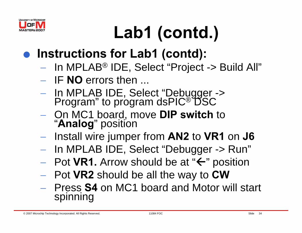
Lab1 (contd.)Instructions for Lab1 (contd):− In MPLAB® IDE, Select “Project -> Build All”− IF NO errors then ...− In MPLAB IDE, Select “Debugger ->
Program” to program dsPIC® DSC− On MC1 board, move DIP switch to
“Analog” position− Install wire jumper from AN2 to VR1 on J6− In MPLAB IDE, Select “Debugger -> Run”− Pot VR1. Arrow should be at “ ” position− Pot VR2 should be all the way to CW− Press S4 on MC1 board and Motor will start
spinning
© 2007 Microchip Technology Incorporated. All Rights Reserved. 11084 FOC Slide 35
Lab1 Results
Follow Lab1 for programming and running software:− Before programming dsPIC® DSC, move DIP to
“ICD” position − Before running, move DIP to “Analog” position
Each Lab has a already created workspace in the appropriate folderUse the created workspace for each lab
© 2007 Microchip Technology Incorporated. All Rights Reserved. 11084 FOC Slide 36
Agenda
PMSM OverviewHands-On ExerciseFOC for PMSM controlHands-On ExercisesSensorless techniquesHands-On ExerciseWrap up, Q&A
© 2007 Microchip Technology Incorporated. All Rights Reserved. 11084 FOC Slide 37
Agenda
FOC for PMSM− FOC Overview− Signal processing− FOC for PMSM
© 2007 Microchip Technology Incorporated. All Rights Reserved. 11084 FOC Slide 38
FOC OverviewSinusoidal excitation with applied current space vector referenced to rotor positionStator current & rotor (magnet) flux interact to produce mutual torque and speedElectronic control required to keep phase at 90 degrees (quadrature) with respect to the rotor in order to optimize torque productionT ∞ Current Space Vector
© 2007 Microchip Technology Incorporated. All Rights Reserved. 11084 FOC Slide 39
FOC Overview
Improved Dynamic ResponseReduced Torque RippleExtended Speed Range Operation is possibleLow Audible Noise & EMI
© 2007 Microchip Technology Incorporated. All Rights Reserved. 11084 FOC Slide 40
Signal Processing
a
b
c
α
β
d
q
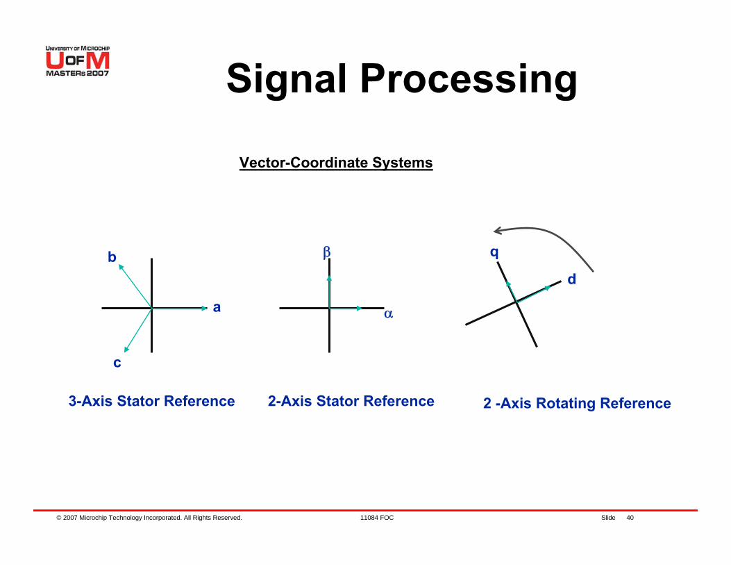
3-Axis Stator Reference 2-Axis Stator Reference 2 -Axis Rotating Reference
Vector-Coordinate Systems
© 2007 Microchip Technology Incorporated. All Rights Reserved. 11084 FOC Slide 41
Signal Processing
3-phase voltages to control the current space vectorTransformations simplify equations and allows control of 3-Phase Motors with conventional techniques as in a DC motor3-phase time variant into a 2-axis time invariant
© 2007 Microchip Technology Incorporated. All Rights Reserved. 11084 FOC Slide 42
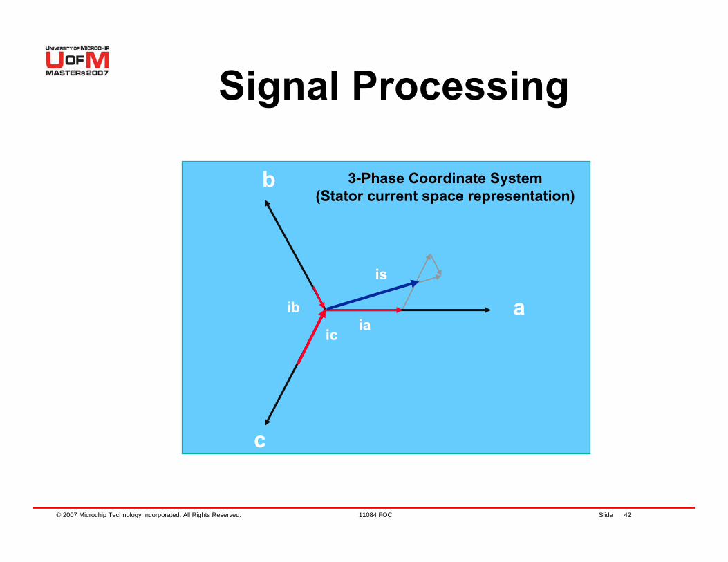
Signal Processing
a
c
iaic
ib
is
b 3-Phase Coordinate System(Stator current space representation)
© 2007 Microchip Technology Incorporated. All Rights Reserved. 11084 FOC Slide 43
Signal Processing
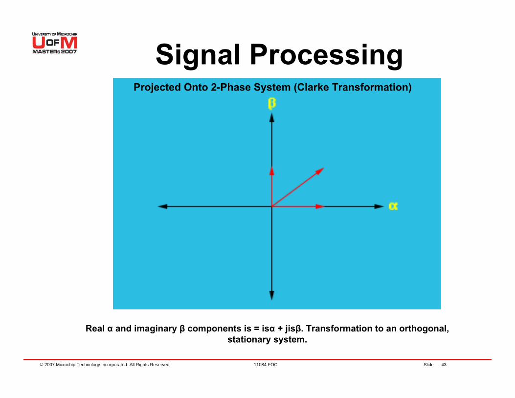
Real α and imaginary β components is = isα + jisβ. Transformation to an orthogonal, stationary system.
Projected Onto 2-Phase System (Clarke Transformation)
© 2007 Microchip Technology Incorporated. All Rights Reserved. 11084 FOC Slide 44
Signal Processing
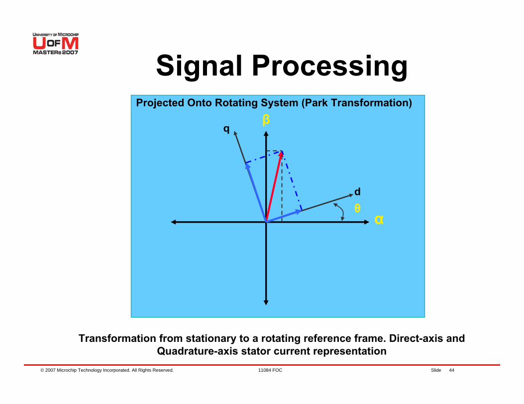
Transformation from stationary to a rotating reference frame. Direct-axis and Quadrature-axis stator current representation
α
β
θd
q
Projected Onto Rotating System (Park Transformation)
© 2007 Microchip Technology Incorporated. All Rights Reserved. 11084 FOC Slide 45
Signal Processing
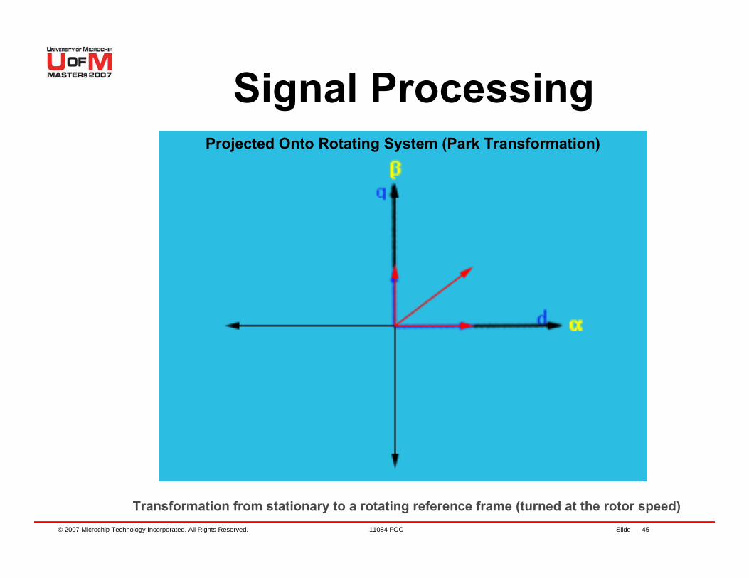
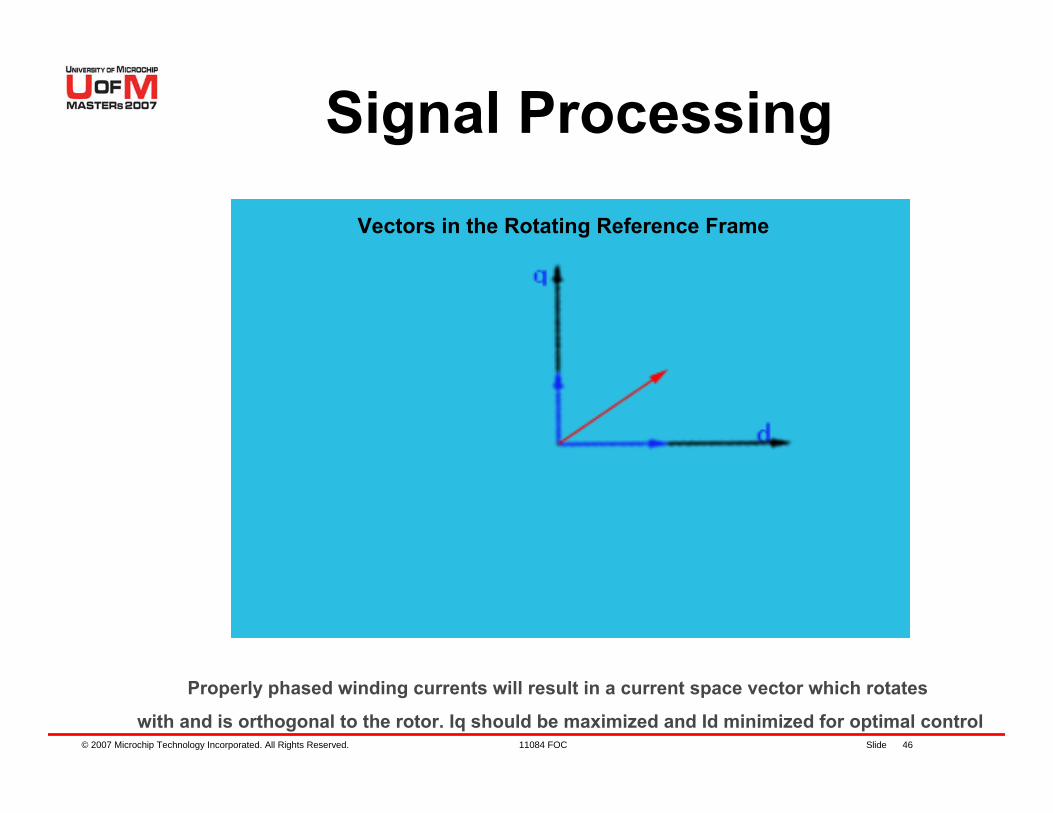
Transformation from stationary to a rotating reference frame (turned at the rotor speed)
Projected Onto Rotating System (Park Transformation)
© 2007 Microchip Technology Incorporated. All Rights Reserved. 11084 FOC Slide 46
Signal Processing
Properly phased winding currents will result in a current space vector which rotates
with and is orthogonal to the rotor. Iq should be maximized and Id minimized for optimal control
Vectors in the Rotating Reference Frame
© 2007 Microchip Technology Incorporated. All Rights Reserved. 11084 FOC Slide 47
Signal Processing
d
q
isiq
id
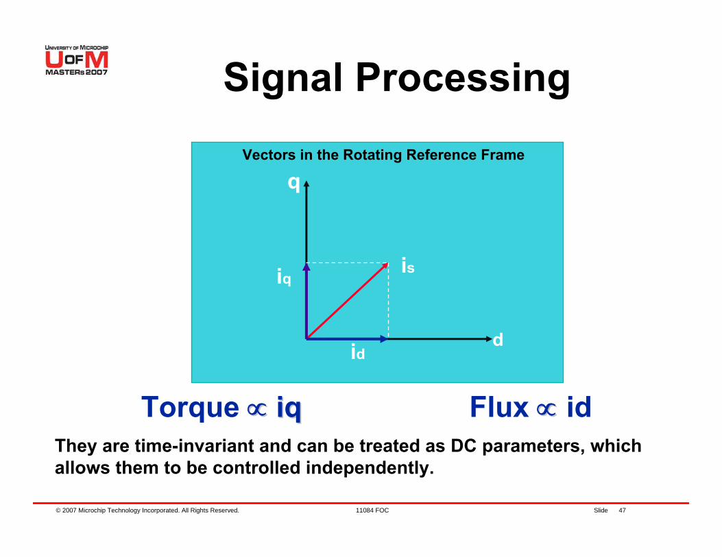
Torque ∝∝ iqiq Flux ∝∝ idThey are time-invariant and can be treated as DC parameters, which allows them to be controlled independently.
Vectors in the Rotating Reference Frame
© 2007 Microchip Technology Incorporated. All Rights Reserved. 11084 FOC Slide 48
FOC for PMSM
ΣΣ
ΣΣ
ΣΣ 3-Phase
Bridge
QEIQEI
SVMPI PI
PI
-
- -
d,q
α,β
θ
iq
id
d,q
α,β
A
BEncoder
iα
iβ
ia
ib
Motor
α,β
a,b,c
Vα
Vβ
Vq
Vd
iq ref
id ref
N ref
Speed and Position
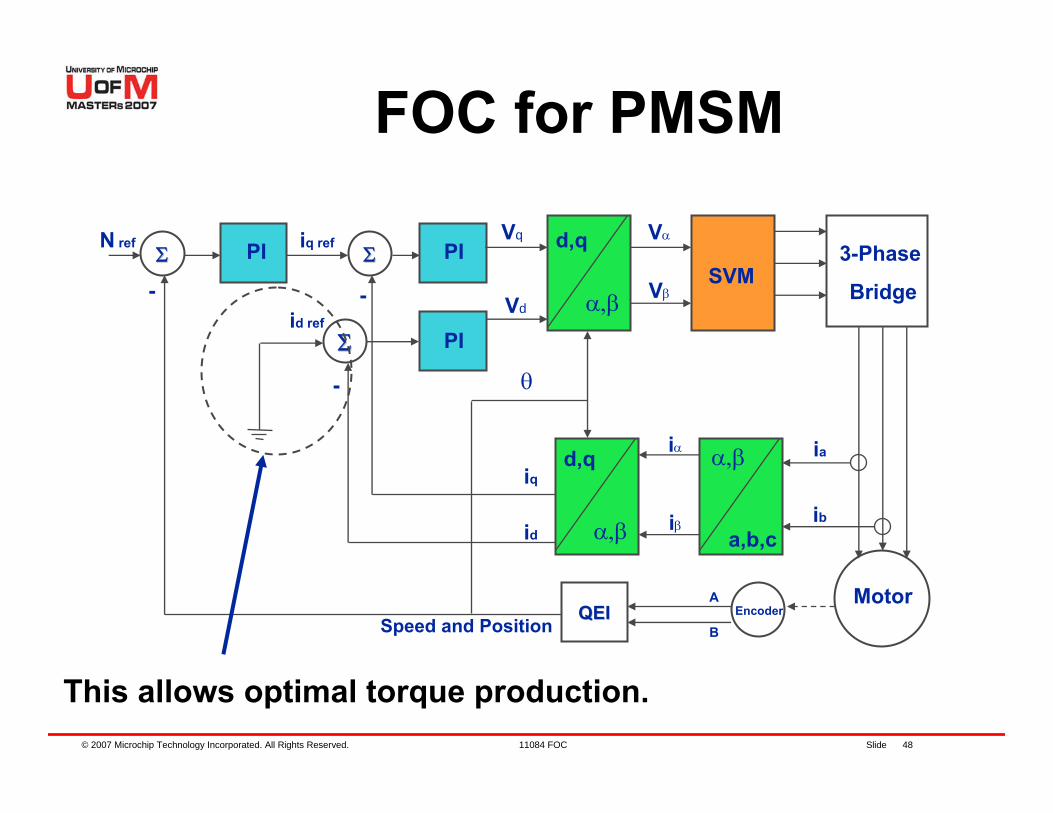
This allows optimal torque production.
© 2007 Microchip Technology Incorporated. All Rights Reserved. 11084 FOC Slide 49
FOC for PMSMPI Controllers operate in the d-q reference frame of the rotor, they are isolated from the sinusoidal variation of motor voltages and currents and so perform equally well at low and high motor speedsIq is servoed to equal the Torque demand and Id is servoed to zero. This gives optimal torque productionThe PI Controller Outputs are transformed to produce three phase voltage signals to the bridge (inverse Park, inverse Clarke folded into SVM)
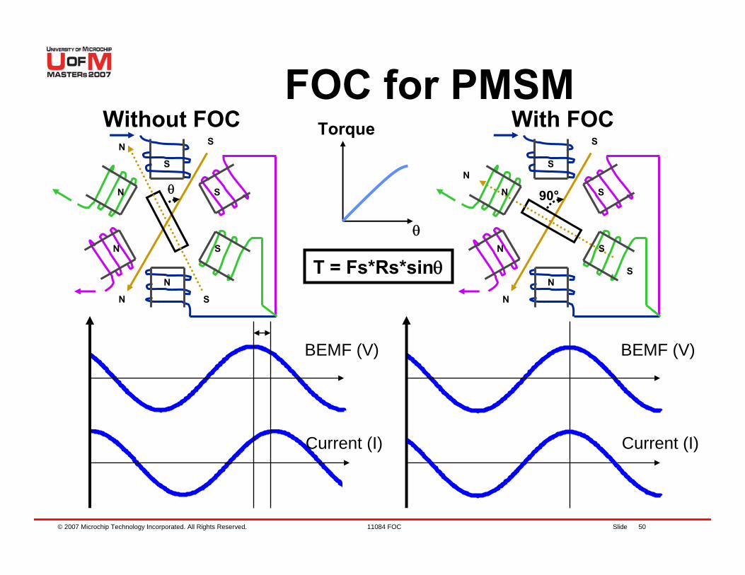
© 2007 Microchip Technology Incorporated. All Rights Reserved. 11084 FOC Slide 50
BEMF (V)
Current (I)
S
N
N
S
θ
S
N
N
S
N
S
Without FOC Torque
θ
T = Fs*Rs*sinθ
FOC for PMSM
BEMF (V)
Current (I)
S
N
N
S
90°
S
N
NS
NS
With FOC
© 2007 Microchip Technology Incorporated. All Rights Reserved. 11084 FOC Slide 51
FOC for PMSM
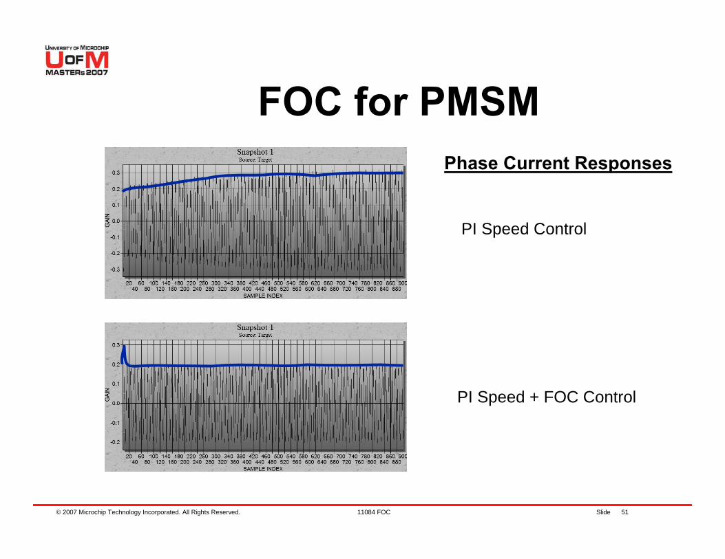
PI Speed Control
PI Speed + FOC Control
Phase Current Responses
© 2007 Microchip Technology Incorporated. All Rights Reserved. 11084 FOC Slide 52
FOC for PMSM
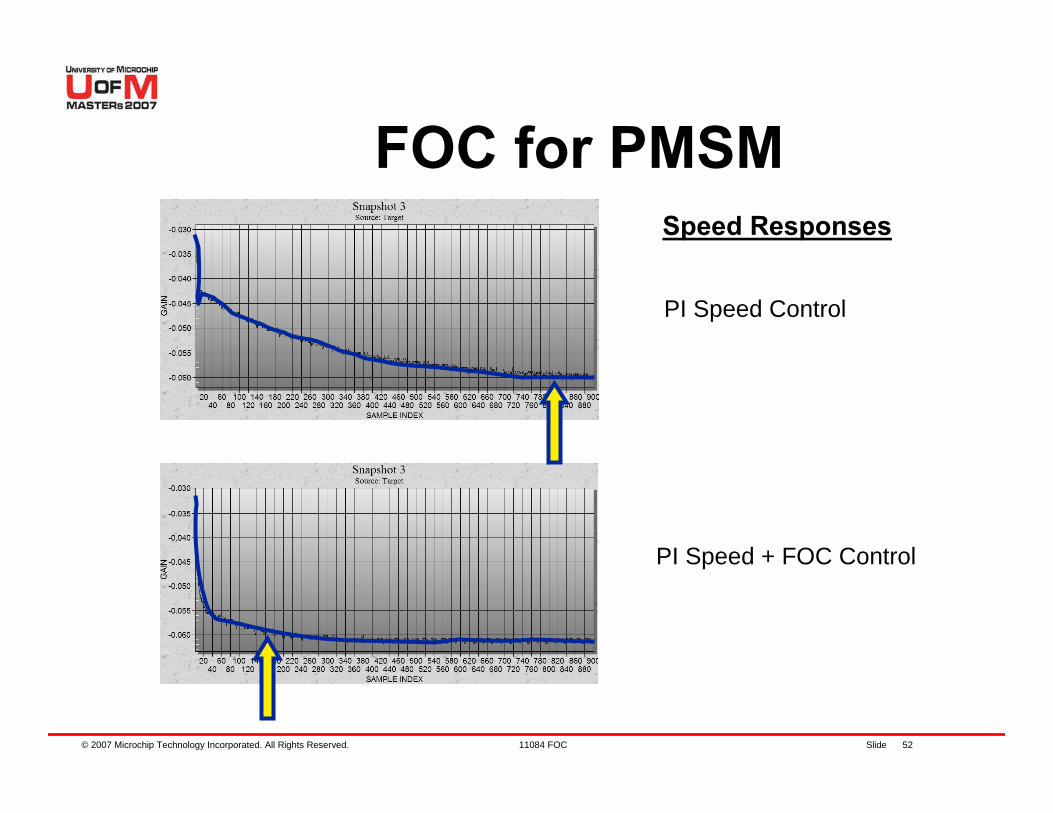
PI Speed Control
PI Speed + FOC Control
Speed Responses
© 2007 Microchip Technology Incorporated. All Rights Reserved. 11084 FOC Slide 53
FOC for PMSM
Field Weakening− What happens when the Back EMF
approaches the supply voltage?− To enable more speed the rotor field
must be weakened− The stator d axis current is set to a
negative value− Torque reduces and speed increases
with field weakening
© 2007 Microchip Technology Incorporated. All Rights Reserved. 11084 FOC Slide 54
FOC for PMSMFOC provides smooth control at low speeds as well as efficient control at high speedsTrapezoidal (BLDC) commutation can be efficient at high speed but introduces torque ripple at low speed and produces audible noiseSinusoidal drive produces smooth control at low speed but is inefficient at high speedsFOC provides the best of both worlds

© 2007 Microchip Technology Incorporated. All Rights Reserved. 11084 FOC Slide 55
Agenda
PMSM OverviewHands-On ExerciseFOC for PMSM controlHands-On ExercisesSensorless techniquesHands-On ExerciseWrap up, Q&A
© 2007 Microchip Technology Incorporated. All Rights Reserved. 11084 FOC Slide 56
Agenda
Hands-On exercises − Lab 2 – Enabling Graphs Using
DMCI− Lab 3 – Tuning PI Parameters
© 2007 Microchip Technology Incorporated. All Rights Reserved. 11084 FOC Slide 57
DMCI
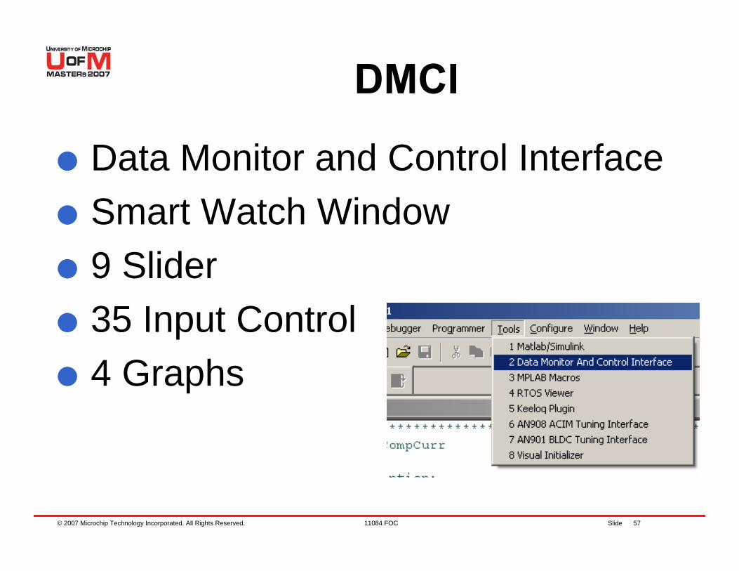
Data Monitor and Control InterfaceSmart Watch Window9 Slider35 Input Control4 Graphs
© 2007 Microchip Technology Incorporated. All Rights Reserved. 11084 FOC Slide 58
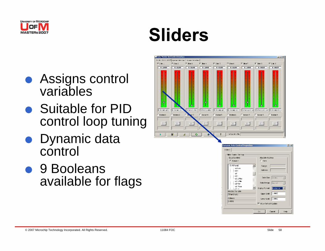
Sliders
Assigns control variablesSuitable for PID control loop tuningDynamic data control9 Booleans available for flags
© 2007 Microchip Technology Incorporated. All Rights Reserved. 11084 FOC Slide 59
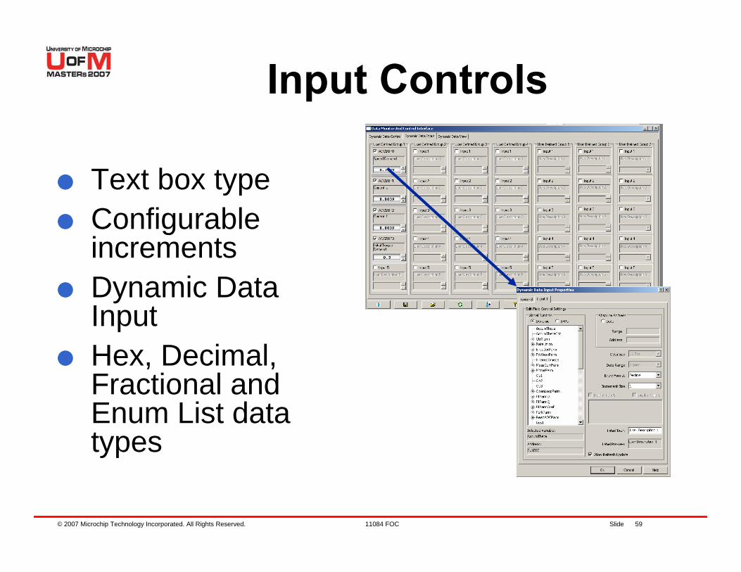
Input Controls
Text box typeConfigurable incrementsDynamic Data InputHex, Decimal, Fractional and Enum List data types
© 2007 Microchip Technology Incorporated. All Rights Reserved. 11084 FOC Slide 60
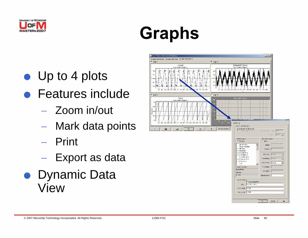
Graphs
Up to 4 plotsFeatures include− Zoom in/out− Mark data points− Print− Export as data
Dynamic Data View
© 2007 Microchip Technology Incorporated. All Rights Reserved. 11084 FOC Slide 61
Lab 2. Enabling Graphs Using DMCI

© 2007 Microchip Technology Incorporated. All Rights Reserved. 11084 FOC Slide 62
Objectives of Lab 2Getting to use DMCIHow to enable a graph using DMCIPlotting variables
© 2007 Microchip Technology Incorporated. All Rights Reserved. 11084 FOC Slide 63
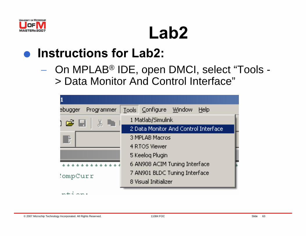
Lab2Instructions for Lab2:− On MPLAB® IDE, open DMCI, select “Tools -
> Data Monitor And Control Interface”
© 2007 Microchip Technology Incorporated. All Rights Reserved. 11084 FOC Slide 64
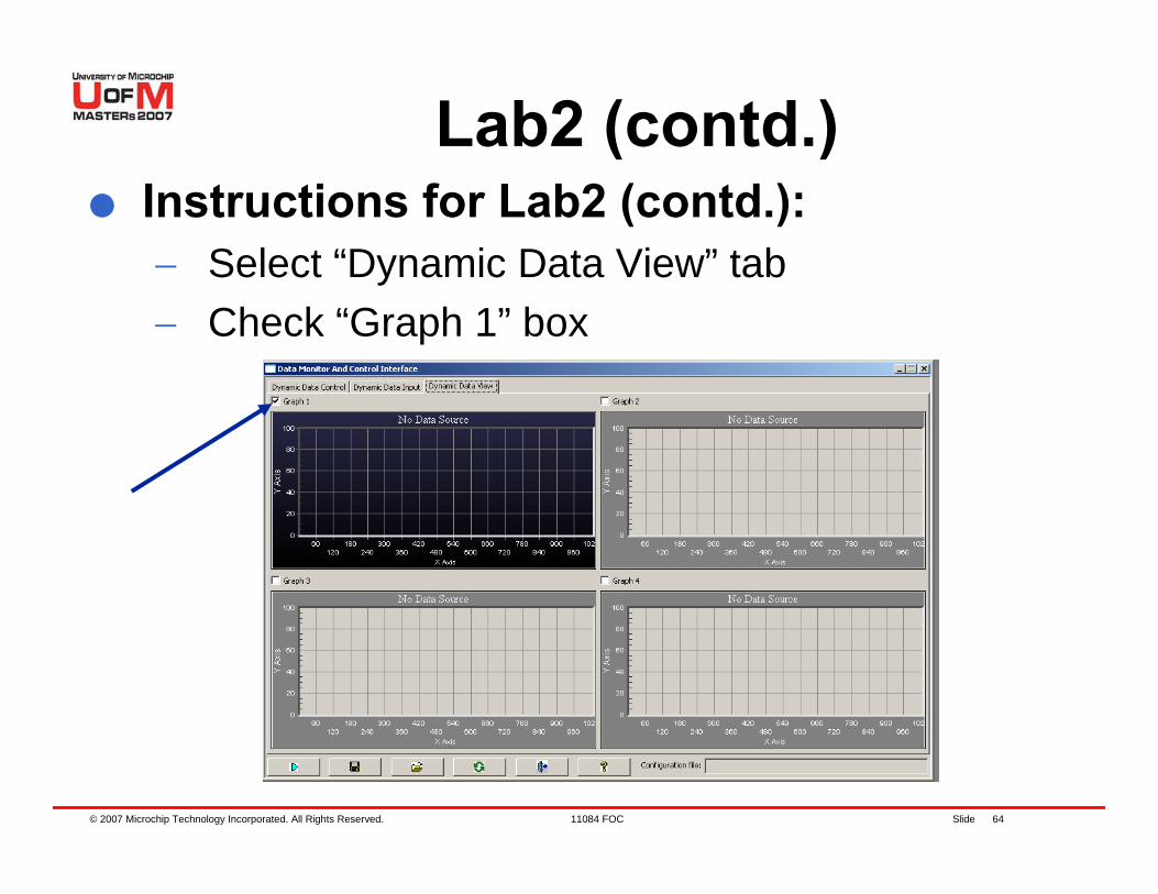
Lab2 (contd.)Instructions for Lab2 (contd.):− Select “Dynamic Data View” tab− Check “Graph 1” box
© 2007 Microchip Technology Incorporated. All Rights Reserved. 11084 FOC Slide 65
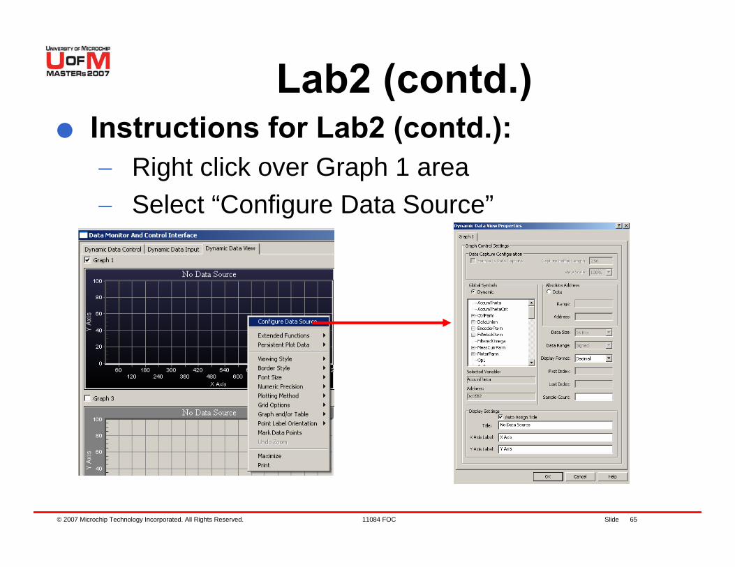
Lab2 (contd.)Instructions for Lab2 (contd.):− Right click over Graph 1 area− Select “Configure Data Source”
© 2007 Microchip Technology Incorporated. All Rights Reserved. 11084 FOC Slide 66
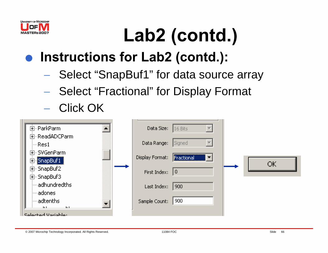
Lab2 (contd.)Instructions for Lab2 (contd.):− Select “SnapBuf1” for data source array− Select “Fractional” for Display Format− Click OK
© 2007 Microchip Technology Incorporated. All Rights Reserved. 11084 FOC Slide 67
Lab2 (contd.)Instructions for Lab2 (contd.):− Assign “SnapBuf2” and SnapBuf3” to Plots 2
and 3.− Halt, Reset and Run application using
MPLAB® IDE− Run motor by pressing S4− After letting the motor run for about 5
seconds, halt execution− Data should be on Graph 1 plot.− This data corresponds to estimated rotor
angle.
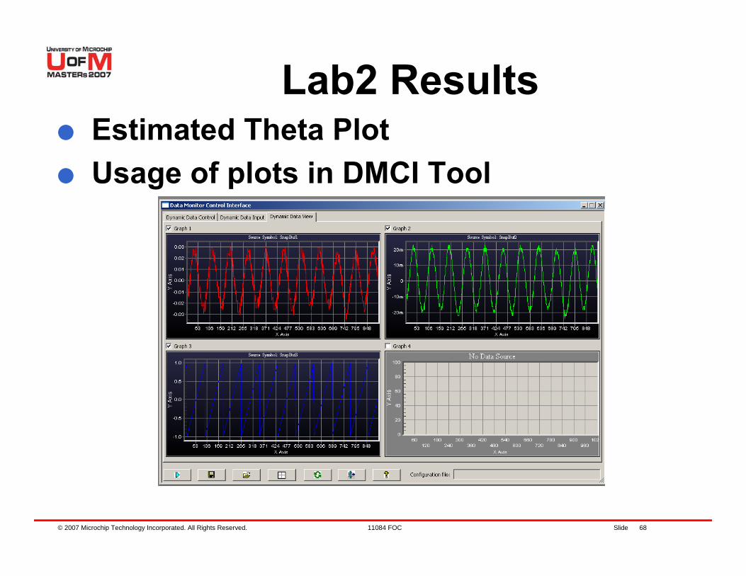
© 2007 Microchip Technology Incorporated. All Rights Reserved. 11084 FOC Slide 68
Lab2 ResultsEstimated Theta PlotUsage of plots in DMCI Tool

© 2007 Microchip Technology Incorporated. All Rights Reserved. 11084 FOC Slide 69
Lab 3. Tuning PI Parameters
© 2007 Microchip Technology Incorporated. All Rights Reserved. 11084 FOC Slide 70
Objectives of Lab 3Tuning PI Parameters for Currents and SpeedUsing Sliders on DMCI tool

© 2007 Microchip Technology Incorporated. All Rights Reserved. 11084 FOC Slide 71
Lab3Instructions for Lab3:− On MPLAB® IDE, open DMCI, select “Tools -
> Data Monitor And Control Interface”
© 2007 Microchip Technology Incorporated. All Rights Reserved. 11084 FOC Slide 72
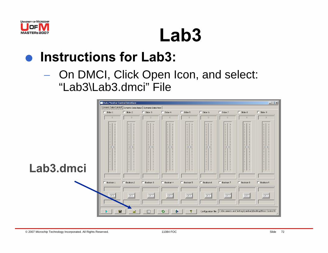
Lab3Instructions for Lab3:− On DMCI, Click Open Icon, and select:
“Lab3\Lab3.dmci” File
Lab3.dmci
© 2007 Microchip Technology Incorporated. All Rights Reserved. 11084 FOC Slide 73
Lab3 (contd.)Instructions for Lab3 (contd.):− Open Lab3 Project− Program dsPIC® DSC− Run motor by pressing S4− By Pressing S6, Speed reference will be
doubled− Analyze transient response on Plots− Tune Speed PI Parameters to reduce
overshoot− Tune Iq PI Parameters to achieve minimum
oscillations on Speed
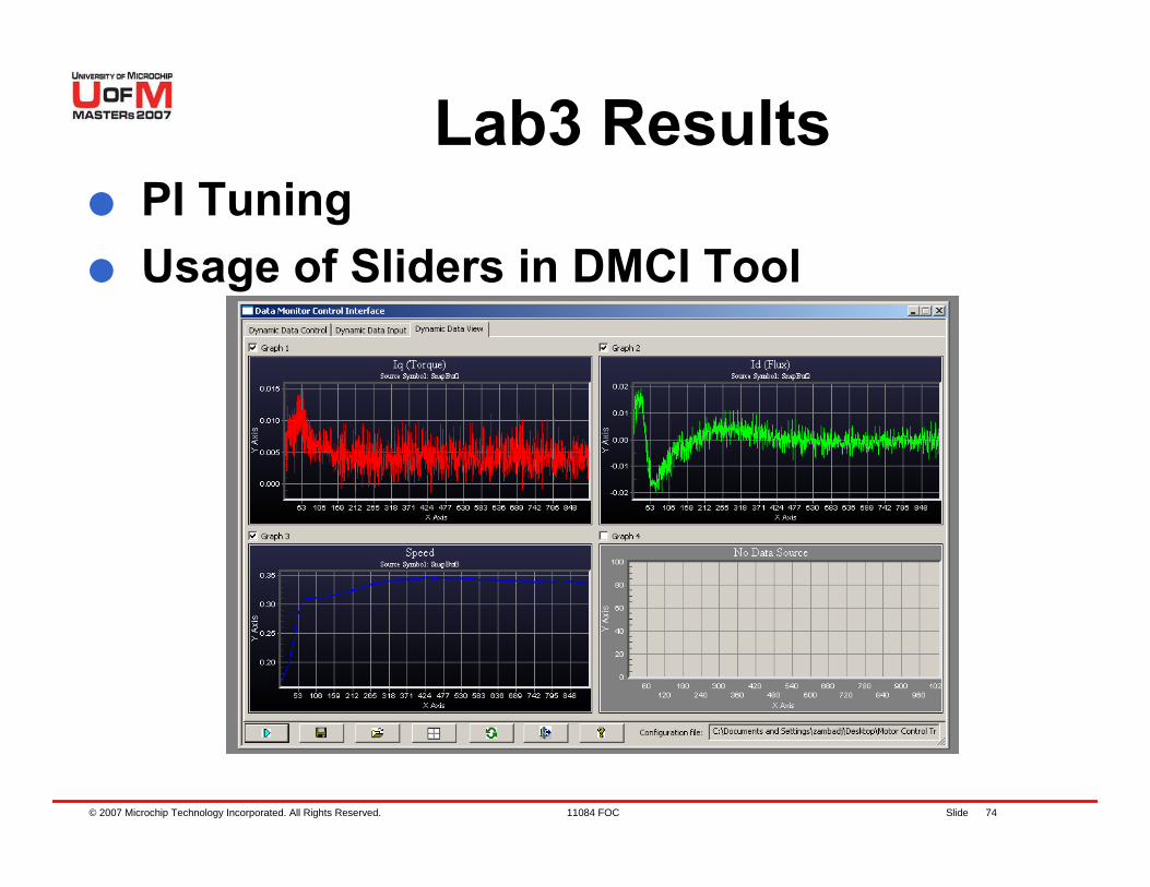
© 2007 Microchip Technology Incorporated. All Rights Reserved. 11084 FOC Slide 74
Lab3 ResultsPI TuningUsage of Sliders in DMCI Tool
© 2007 Microchip Technology Incorporated. All Rights Reserved. 11084 FOC Slide 75
Agenda
PMSM OverviewHands-On ExerciseFOC for PMSM controlHands-On ExercisesSensorless techniquesHands-On ExerciseWrap up, Q&A
© 2007 Microchip Technology Incorporated. All Rights Reserved. 11084 FOC Slide 76
Agenda
Sensorless Techniques− Six step for BLDC− FOC for PMSM
© 2007 Microchip Technology Incorporated. All Rights Reserved. 11084 FOC Slide 77
Six step for BLDC
Commutation is implemented in six discrete steps per electrical revolutionHall sensors can be used to indicate when commutation is requiredBack EMF can be used to provide the same information
© 2007 Microchip Technology Incorporated. All Rights Reserved. 11084 FOC Slide 78
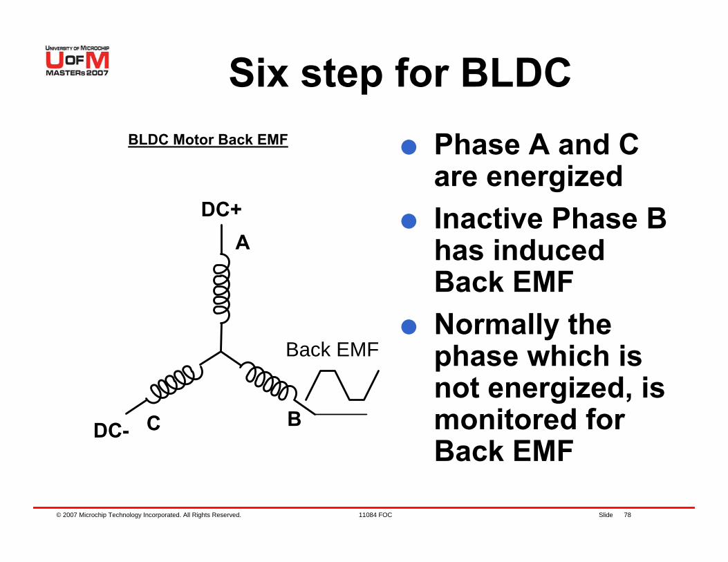
Six step for BLDC
A
C B
DC+
DC-
Back EMF
Phase A and C are energizedInactive Phase B has induced Back EMFNormally the phase which is not energized, is monitored for Back EMF
BLDC Motor Back EMF
© 2007 Microchip Technology Incorporated. All Rights Reserved. 11084 FOC Slide 79
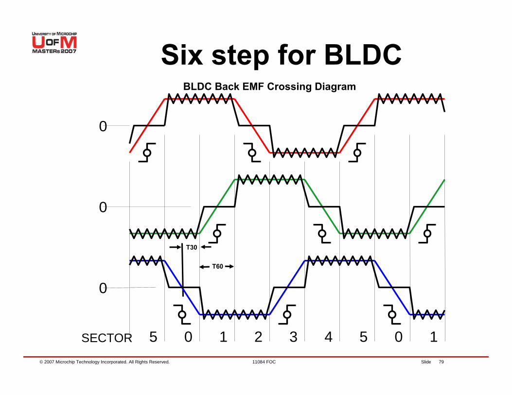
T30
T60
5 0 1 2 3 4 5 0 1SECTOR
0
0
0
Six step for BLDCBLDC Back EMF Crossing Diagram
© 2007 Microchip Technology Incorporated. All Rights Reserved. 11084 FOC Slide 80
In every electrical cycle, there are periods when each phase is not being driven.During these regions one end of the inactive phase is referenced to the star point and the other is monitored.The monitored voltage will cross the 1/2 VDD point at 30 electrical degrees.Knowing the last “zero crossing” time we know the 60 electrical degree time (T60)T60 divided by 2 = T30 is loaded in TMR2.The ISR of TMR2 then commutes the next pair of windings at T30 seconds later
Six step for BLDCThe Back EMF “zero crossing” method in detail
© 2007 Microchip Technology Incorporated. All Rights Reserved. 11084 FOC Slide 81
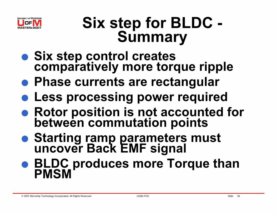
Six step for BLDC -Summary
Six step control creates comparatively more torque ripplePhase currents are rectangularLess processing power requiredRotor position is not accounted for between commutation pointsStarting ramp parameters must uncover Back EMF signalBLDC produces more Torque than PMSM
© 2007 Microchip Technology Incorporated. All Rights Reserved. 11084 FOC Slide 82
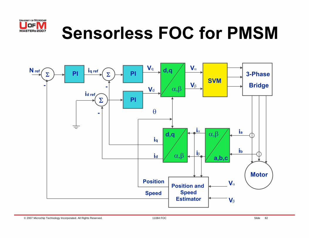
Sensorless FOC for PMSM
ΣΣ
ΣΣ
ΣΣ 3-Phase
Bridge
Position and Speed
Estimator
SVMPI PI
PI
-
- -
d,q
α,β
θ
iq
id
d,q
α,β
Speed
iα
iβ
ia
ib
Motor
α,β
a,b,c
Vα
Vβ
Vq
Vd
iq ref
id ref
N ref
Position Vα
Vβ
© 2007 Microchip Technology Incorporated. All Rights Reserved. 11084 FOC Slide 83
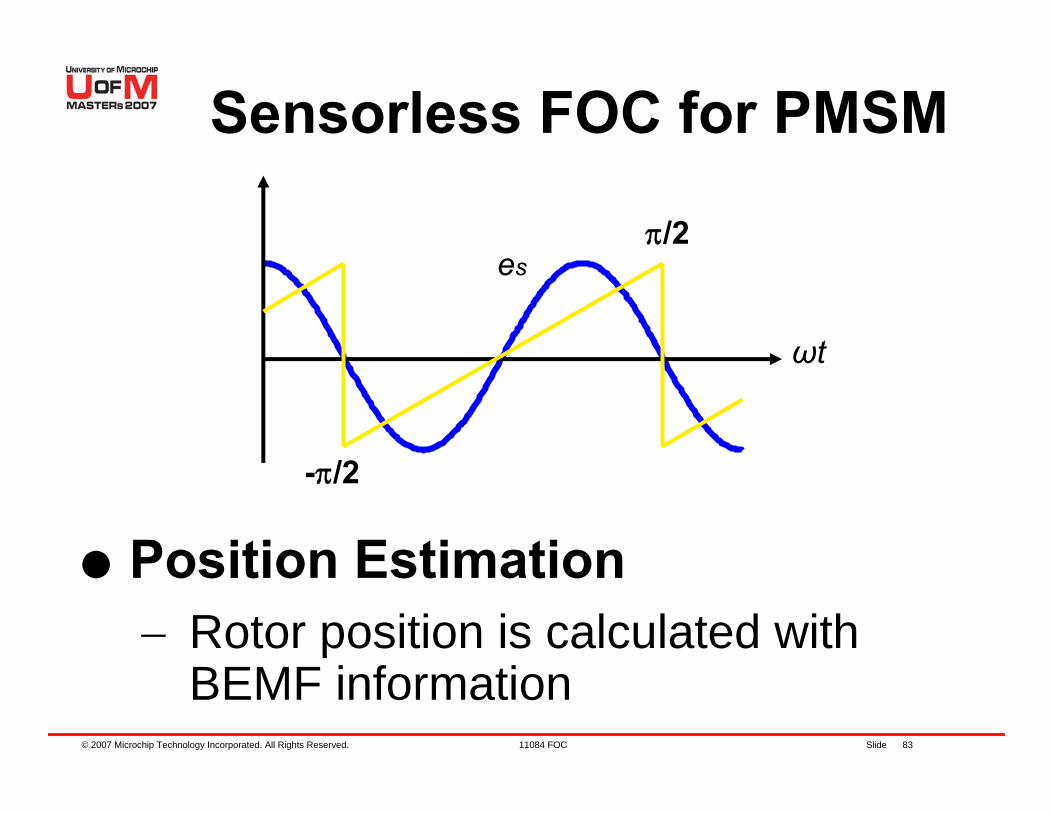
Sensorless FOC for PMSM
es
ωt
-π/2
π/2
Position Estimation− Rotor position is calculated with
BEMF information
© 2007 Microchip Technology Incorporated. All Rights Reserved. 11084 FOC Slide 84
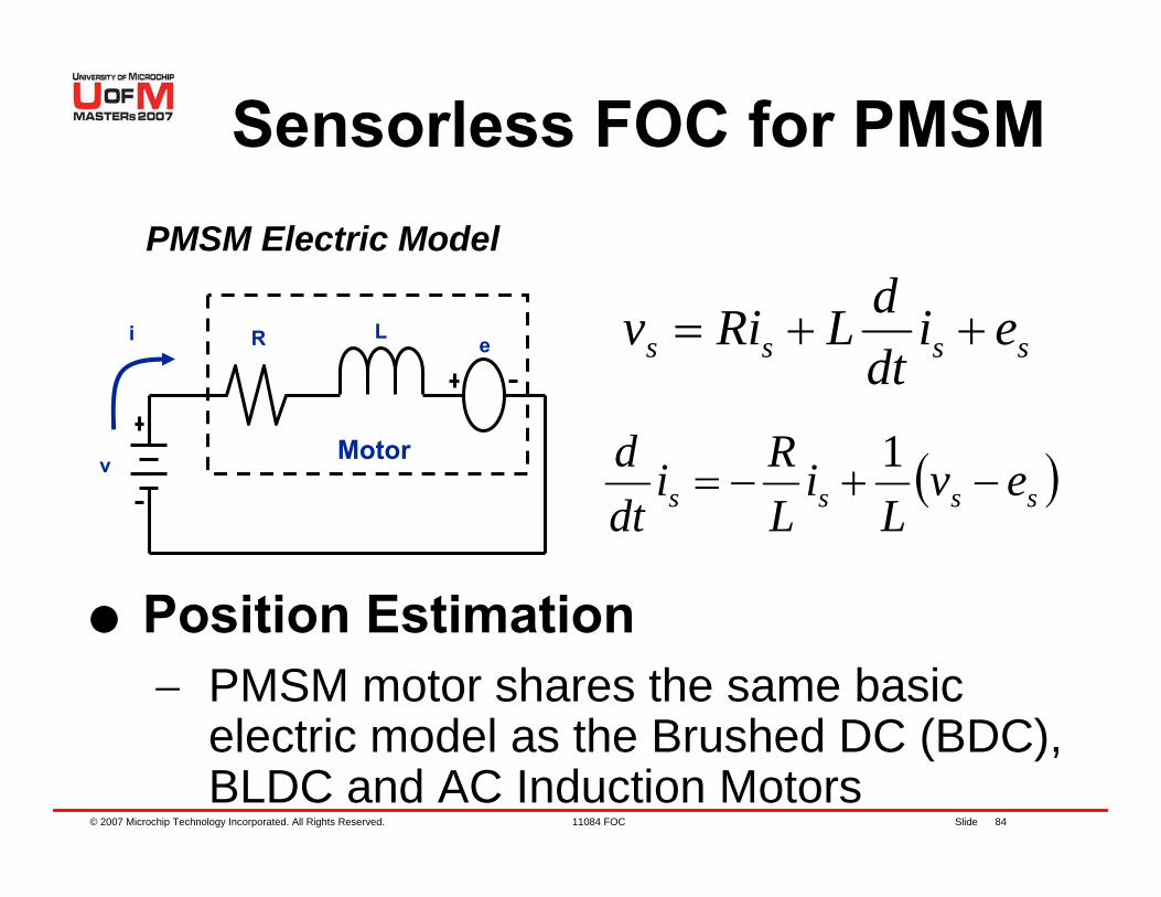
Sensorless FOC for PMSM
( )ssss evL
iLRi
dtd
−+−=1
e
Motor
R L
v
i
PMSM Electric Model
Position Estimation− PMSM motor shares the same basic
electric model as the Brushed DC (BDC), BLDC and AC Induction Motors
ssss eidtdLRiv ++=
© 2007 Microchip Technology Incorporated. All Rights Reserved. 11084 FOC Slide 85
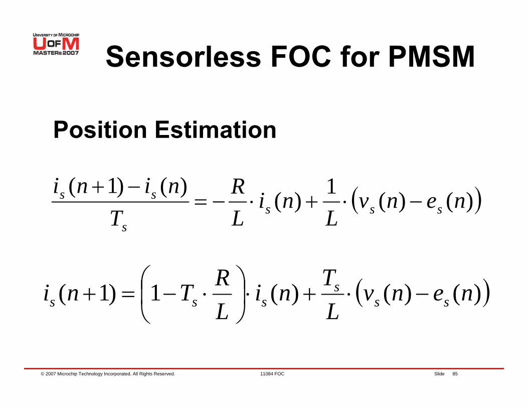
Sensorless FOC for PMSM
( ))()(1)()()1( nenvL
niLR
Tnini
ssss
ss −⋅+⋅−=−+
( ))()()(1)1( nenvLTni
LRTni ss
ssss −⋅+⋅⎟
⎠⎞
⎜⎝⎛ ⋅−=+
Position Estimation
© 2007 Microchip Technology Incorporated. All Rights Reserved. 11084 FOC Slide 86
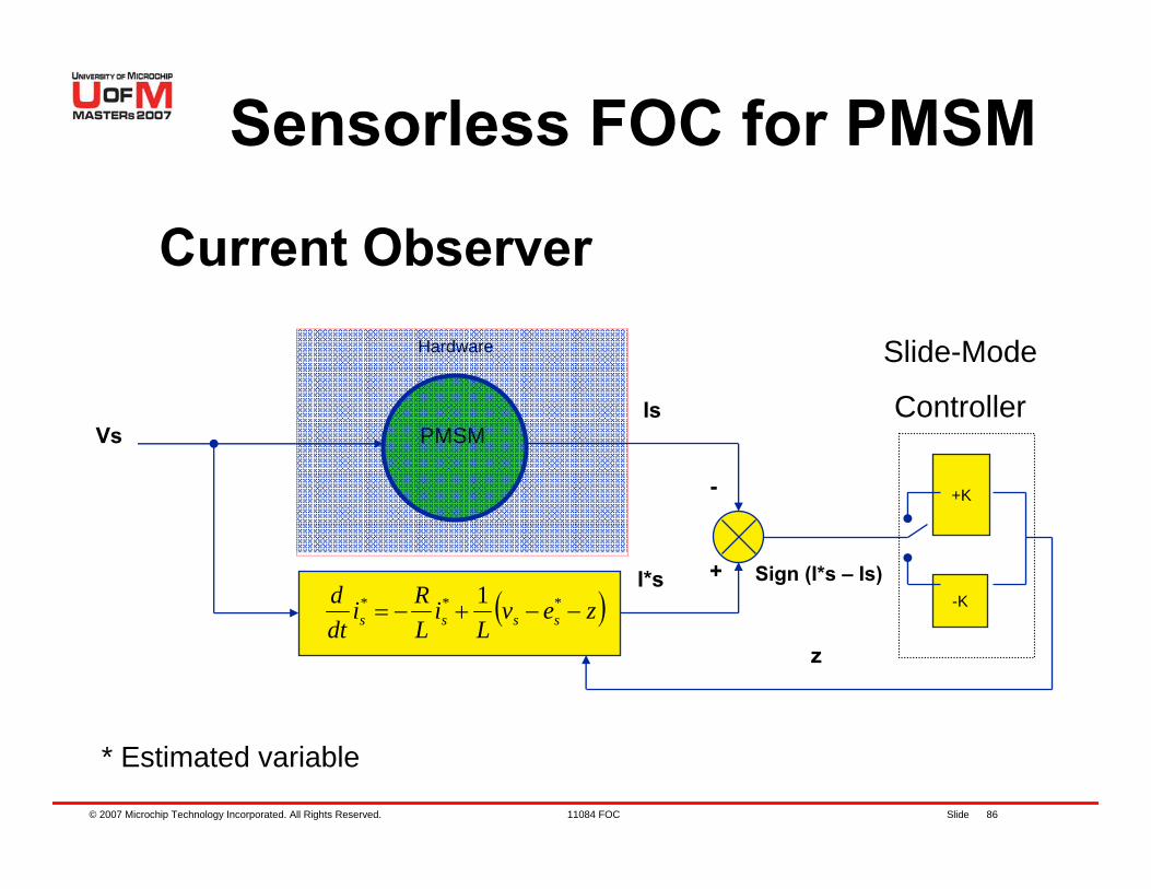
Sensorless FOC for PMSM
-K
+K
( )zevL
iLRi
dtd
ssss −−+−= *** 1
Vs PMSMIs
I*s
* Estimated variable
+
-
Sign (I*s – Is)
Slide-Mode
Controller
z
Hardware
Current Observer
© 2007 Microchip Technology Incorporated. All Rights Reserved. 11084 FOC Slide 87
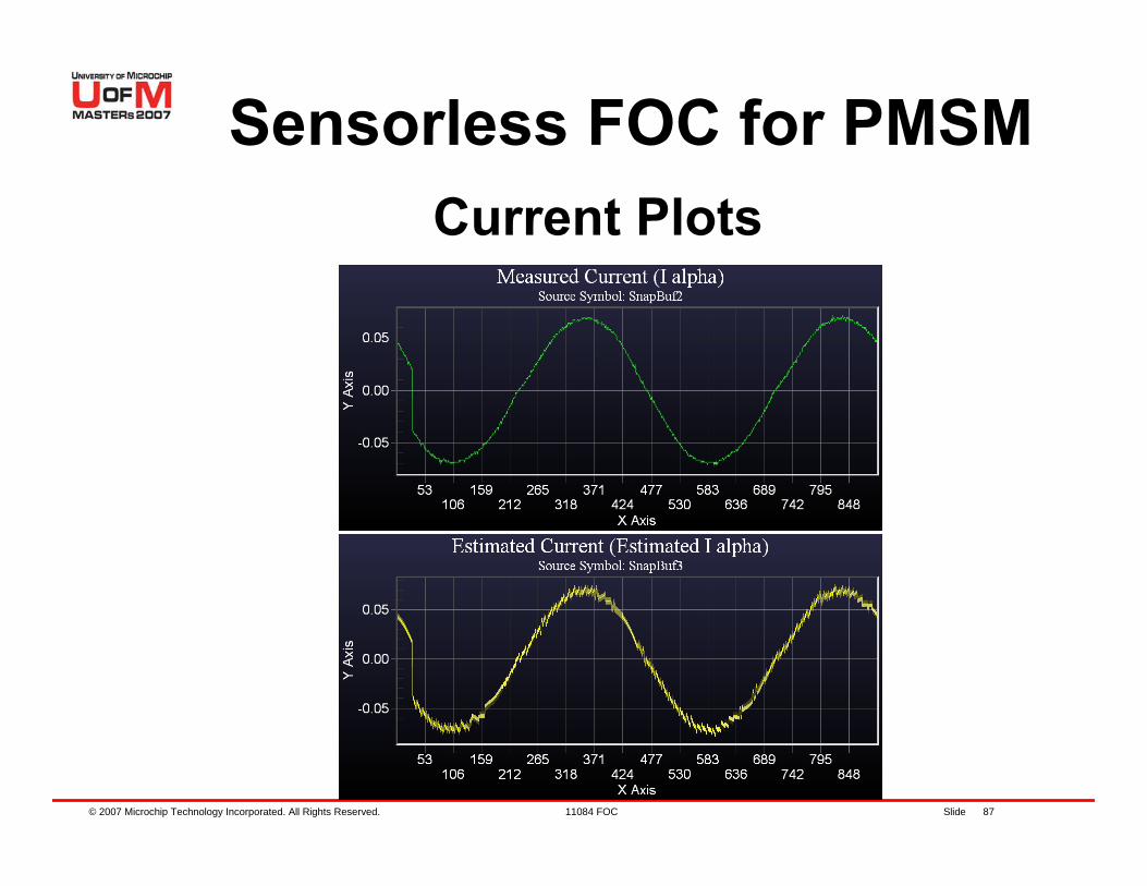
Sensorless FOC for PMSMCurrent Plots
© 2007 Microchip Technology Incorporated. All Rights Reserved. 11084 FOC Slide 88
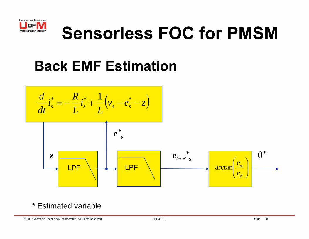
Sensorless FOC for PMSM
( )zevL
iLRi
dtd
ssss −−+−= *** 1
LPF
e*s
⎟⎟⎠
⎞⎜⎜⎝
⎛
β
α
eearctan
θ*zLPF
efiltered*s
* Estimated variable
Back EMF Estimation
© 2007 Microchip Technology Incorporated. All Rights Reserved. 11084 FOC Slide 89
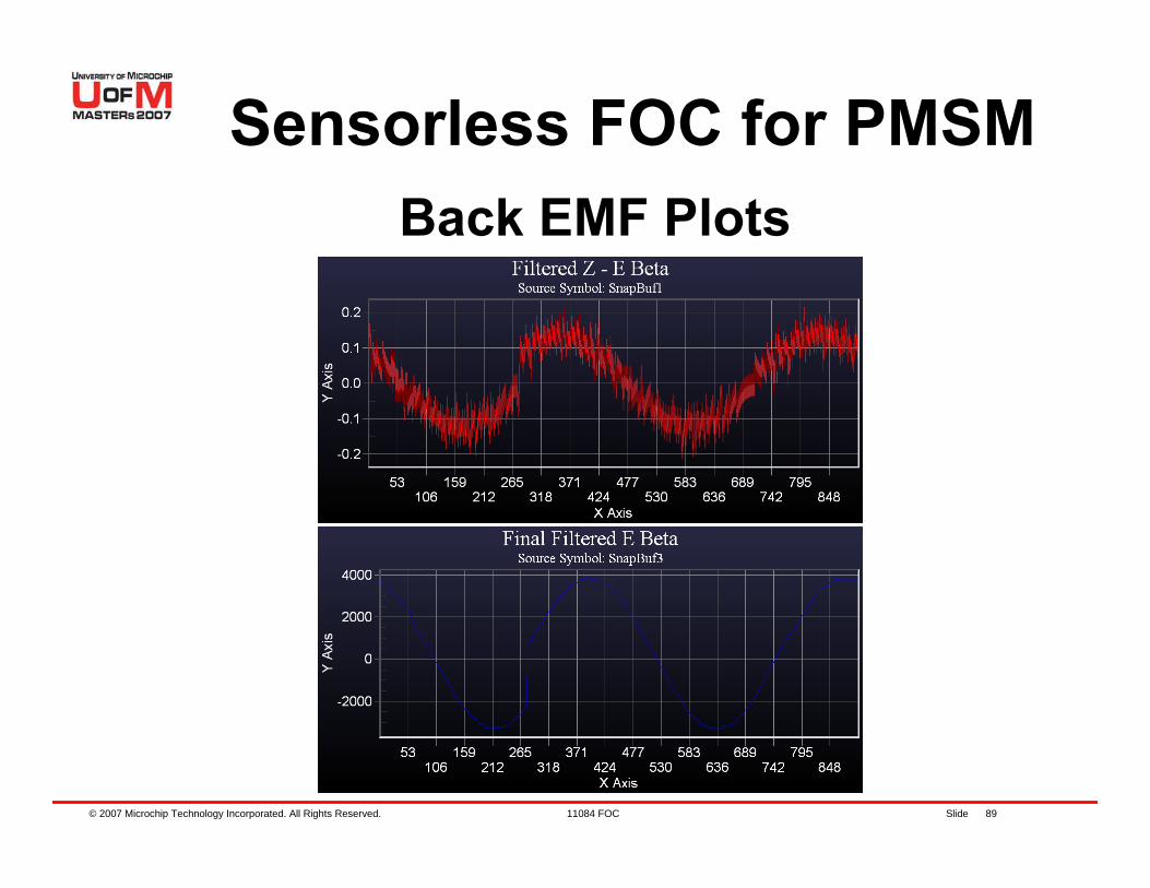
Sensorless FOC for PMSMBack EMF Plots
© 2007 Microchip Technology Incorporated. All Rights Reserved. 11084 FOC Slide 90
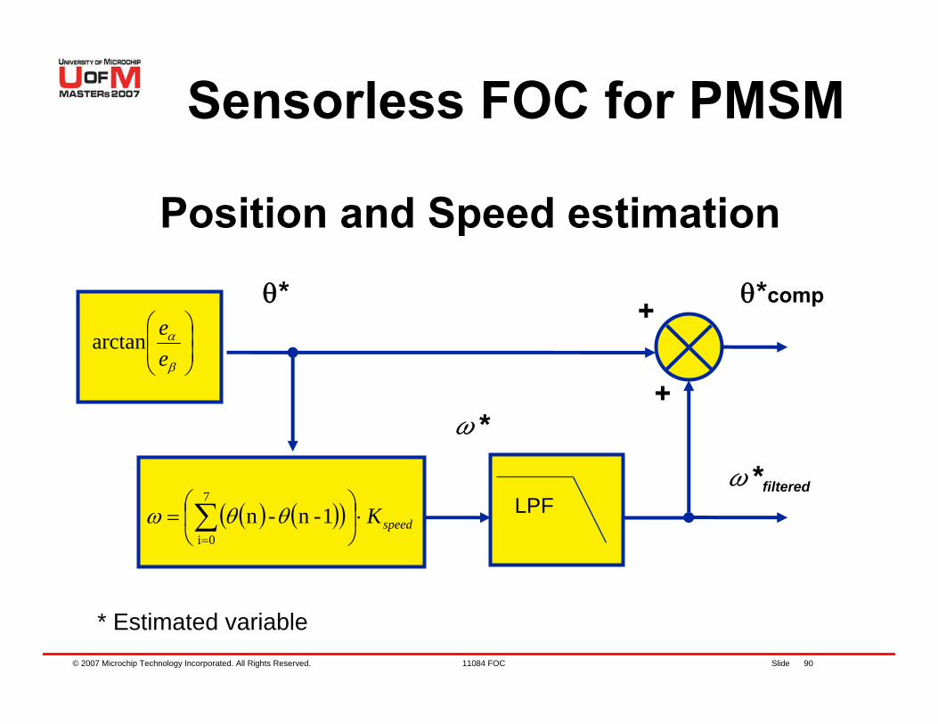
Sensorless FOC for PMSM
⎟⎟⎠
⎞⎜⎜⎝
⎛
β
α
eearctan
θ*
( ) ( )( ) speedK⋅⎟⎠
⎞⎜⎝
⎛= ∑
=
7
0i1-n-n θθω
+
+ θ*comp
ω*
LPFω*filtered
* Estimated variable
Position and Speed estimation
© 2007 Microchip Technology Incorporated. All Rights Reserved. 11084 FOC Slide 91
Sensorless FOC for PMSM
Phase Compensation− The inherent position filtering is
compensated− Speed range is divided into parts
with compensation applied to each− Spread sheet calculator supplied
© 2007 Microchip Technology Incorporated. All Rights Reserved. 11084 FOC Slide 92
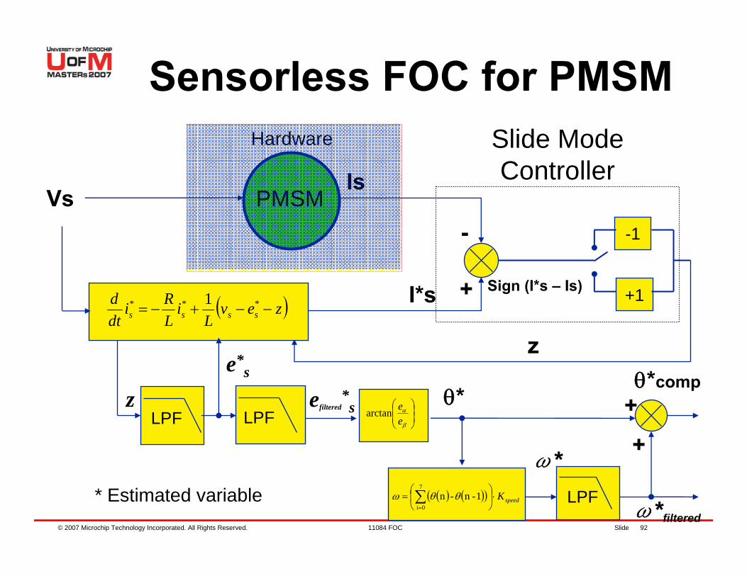
Sensorless FOC for PMSM
Vs PMSMIs
I*s
* Estimated variable
+
- -1
+1Sign (I*s – Is)
Slide Mode Controller
z
Hardware
( )zevL
iLRi
dtd
ssss −−+−= *** 1
LPF
e*s
zLPF
efiltered*s
⎟⎟⎠
⎞⎜⎜⎝
⎛
β
α
eearctan
θ*
( ) ( )( ) speedK⋅⎟⎠
⎞⎜⎝
⎛= ∑
=
7
0i1-n-n θθω
+
+θ*comp
ω*LPF
ω*filtered
© 2007 Microchip Technology Incorporated. All Rights Reserved. 11084 FOC Slide 93
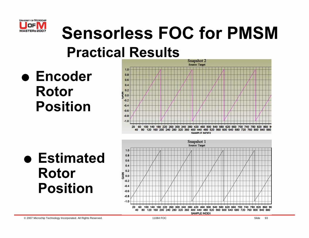
Sensorless FOC for PMSM
Encoder Rotor Position
Estimated Rotor Position
Practical Results
© 2007 Microchip Technology Incorporated. All Rights Reserved. 11084 FOC Slide 94
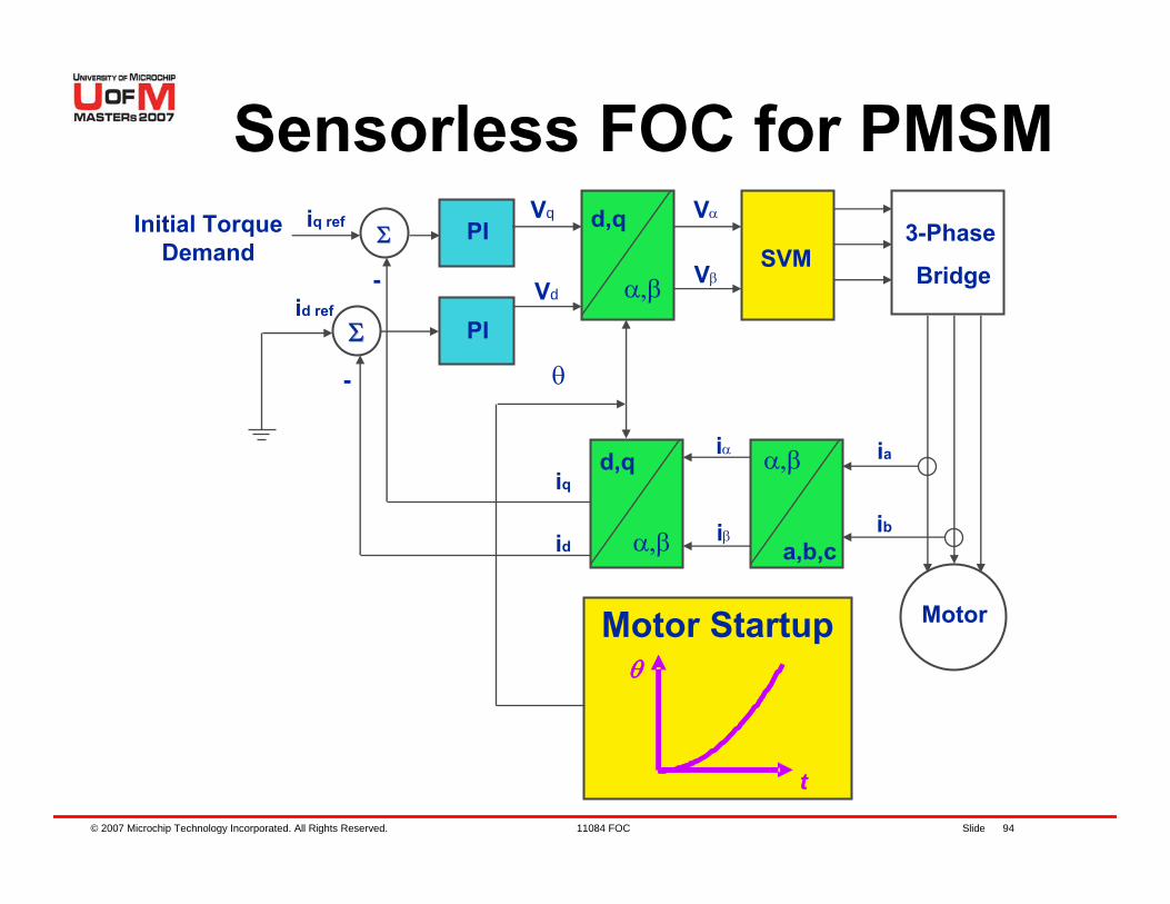
ΣΣ
ΣΣ
3-Phase
BridgeSVM
PI
PI
-
-
d,q
α,β
θ
iq
id
d,q
α,β
iα
iβ
ia
ib
Motor
α,β
a,b,c
Vα
Vβ
Vq
Vd
iq ref
id ref
Motor Startupθ
t
θ
t
Initial Torque Demand
Sensorless FOC for PMSM
© 2007 Microchip Technology Incorporated. All Rights Reserved. 11084 FOC Slide 95
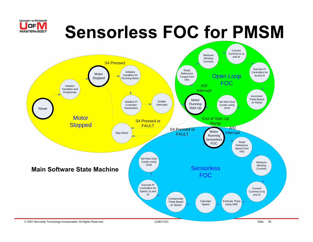
Sensorless FOC for PMSM
Reset
Initialize Variables and Peripherals
Motor Stopped
Initialize Variables for
Running Motor
Initialize PI Controller
Parameters
Enable Interrupts
Motor Running Start Up
Read Reference
Torque from VR1
Measure Winding Currents
Convert Currents to Iq
and Id
Execute PI Controllers for
Iq and Id
Increment Theta Based
on RampSet New Duty Cycles using
SVM
Motor Running
Sensorless FOC Read
Reference Speed from
VR2
Measure Winding Currents
Convert Currents to Iq
and Id
Estimate Theta using SMC
Calculate Speed
Compensate Theta Based
on Speed
Execute PI Controllers for Speed, Iq and
Id
Set New Duty Cycles using
SVM
Stop Motor
A/D Interrupt
A/D Interrupt
End of Start Up Ramp
S4 Pressed
S4 Pressed or FAULT
S4 Pressed or FAULT
Motor Stopped
Open LoopFOC
Sensorless FOC
Main Software State Machine
© 2007 Microchip Technology Incorporated. All Rights Reserved. 11084 FOC Slide 96
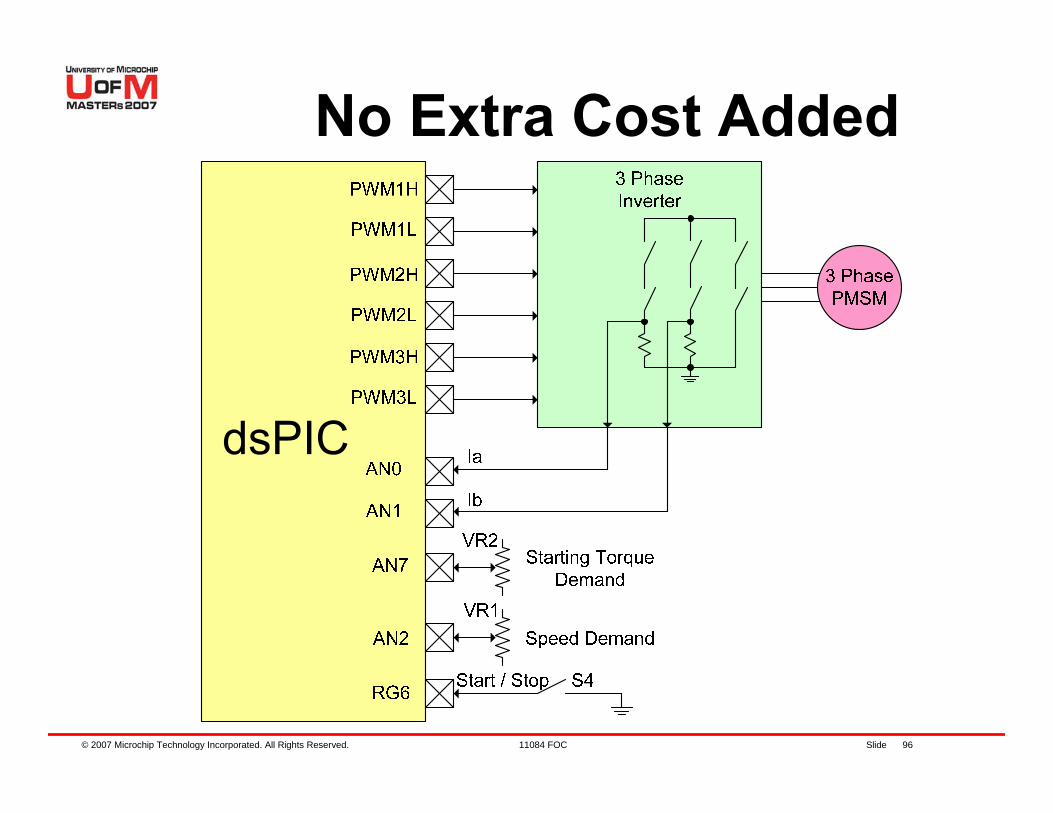
No Extra Cost Added

© 2007 Microchip Technology Incorporated. All Rights Reserved. 11084 FOC Slide 97
Agenda
PMSM OverviewHands-On ExerciseFOC for PMSM controlHands-On ExercisesSensorless techniquesHands-On ExerciseWrap up, Q&A
© 2007 Microchip Technology Incorporated. All Rights Reserved. 11084 FOC Slide 98
Agenda
Hands on exercises − Lab 4 – Tuning Sensorless
Parameters
© 2007 Microchip Technology Incorporated. All Rights Reserved. 11084 FOC Slide 99
Lab 4. Tuning Sensorless Parameters
© 2007 Microchip Technology Incorporated. All Rights Reserved. 11084 FOC Slide 100
Objectives of Lab 4Tuning Sensorless Parameters for Open Loop. Lock Times and End Speed.Tuning Sensorless Parameter for Closed Loop. Slide Mode Controller Gain.

© 2007 Microchip Technology Incorporated. All Rights Reserved. 11084 FOC Slide 101
Lab4Instructions for Lab4:− On MPLAB® IDE, open DMCI, select “Tools -
> Data Monitor And Control Interface”

© 2007 Microchip Technology Incorporated. All Rights Reserved. 11084 FOC Slide 102
Lab4Instructions for Lab4:− On DMCI, Click Open Icon, and select:
“Lab4\Lab4.dmci” File
Lab4.dmci
© 2007 Microchip Technology Incorporated. All Rights Reserved. 11084 FOC Slide 103
Lab4 (contd.)Instructions for Lab4 (contd.):− Open Lab4 Project− Program dsPIC® DSC− Run motor by pressing S4− Motor will not transition to closed loop− Halt and analyze Plots− Set K slide to .9. Run and analyze− Set K slide to .1. Run and analyze− Change End Speed from Slide Bars.− What happens to Estimated Current?− What happens to Theta?
© 2007 Microchip Technology Incorporated. All Rights Reserved. 11084 FOC Slide 104
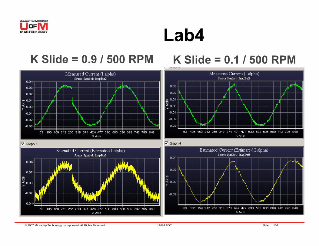
K Slide = 0.9 / 500 RPM K Slide = 0.1 / 500 RPM
Lab4
© 2007 Microchip Technology Incorporated. All Rights Reserved. 11084 FOC Slide 105
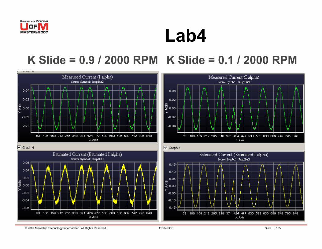
Lab4K Slide = 0.1 / 2000 RPMK Slide = 0.9 / 2000 RPM
© 2007 Microchip Technology Incorporated. All Rights Reserved. 11084 FOC Slide 106
Lab4 Results
K Slide tuning. Slide Mode Controller Gain should be high enough to “track”measured current.Gain should be low enough to keep Theta as clean as possible.Estimated current and measured current should be on the same scale.End Speed should be enough to get a clean Theta.

© 2007 Microchip Technology Incorporated. All Rights Reserved. 11084 FOC Slide 107
Agenda
PMSM OverviewHands-On ExerciseFOC for PMSM controlHands-On ExercisesSensorless techniquesHands-On ExerciseWrap up, Q&A

© 2007 Microchip Technology Incorporated. All Rights Reserved. 11084 FOC Slide 108
Agenda
Wrap up, Q&A− Summary− Dev Tools used in this class− Resources
© 2007 Microchip Technology Incorporated. All Rights Reserved. 11084 FOC Slide 109
Summary
PMSM− High efficiency and smooth torque
are advantageousFOC− Provides optimal torque control− Can be run with or without Position
Sensors− Applicable for ACIM
© 2007 Microchip Technology Incorporated. All Rights Reserved. 11084 FOC Slide 110
Dev Tools used in this class
dsPICDEM™ MC1 Motor Control Development Board (DM300020)dsPICDEM MC1L 3-Phase Low Voltage Power Module (DM300022)3-Phase BLDC Low Voltage Motor 24V (AC300020)MPLAB® ICD 2 In-Circuit Debugger/Programmer (DV164005)
© 2007 Microchip Technology Incorporated. All Rights Reserved. 11084 FOC Slide 111
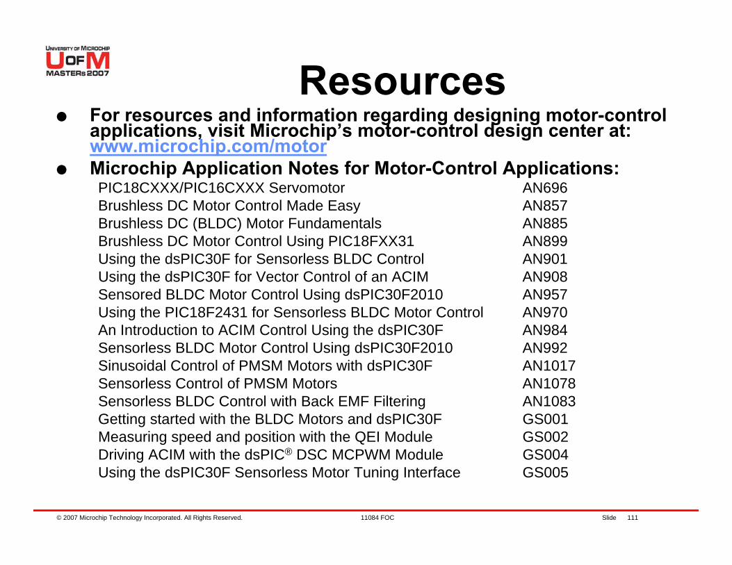
ResourcesFor resources and information regarding designing motor-control applications, visit Microchip’s motor-control design center at: www.microchip.com/motorMicrochip Application Notes for Motor-Control Applications:
PIC18CXXX/PIC16CXXX Servomotor AN696Brushless DC Motor Control Made Easy AN857Brushless DC (BLDC) Motor Fundamentals AN885Brushless DC Motor Control Using PIC18FXX31 AN899Using the dsPIC30F for Sensorless BLDC Control AN901Using the dsPIC30F for Vector Control of an ACIM AN908Sensored BLDC Motor Control Using dsPIC30F2010 AN957Using the PIC18F2431 for Sensorless BLDC Motor Control AN970An Introduction to ACIM Control Using the dsPIC30F AN984Sensorless BLDC Motor Control Using dsPIC30F2010 AN992Sinusoidal Control of PMSM Motors with dsPIC30F AN1017Sensorless Control of PMSM Motors AN1078Sensorless BLDC Control with Back EMF Filtering AN1083Getting started with the BLDC Motors and dsPIC30F GS001Measuring speed and position with the QEI Module GS002Driving ACIM with the dsPIC® DSC MCPWM Module GS004Using the dsPIC30F Sensorless Motor Tuning Interface GS005
© 2007 Microchip Technology Incorporated. All Rights Reserved. 11084 FOC Slide 112
Thank You
Note: The Microchip name and logo are registered trademarks of Microchip Technology Inc. in the U.S.A. and other countries.
All other trademarks mentioned herein are property of their respective companies.
© 2007 Microchip Technology Incorporated. All Rights Reserved. 11084 FOC Slide 113
TrademarksThe Microchip name and logo, the Microchip logo, Accuron, dsPIC, KeeLoq, KeeLoq logo, microID, MPLAB, PIC, PICmicro, PICSTART, PRO MATE, rfPICand SmartShunt are registered trademarks of Microchip Technology Incorporated in the U.S.A. and other countries.AmpLab, FilterLab, Linear Active Thermistor, Migratable Memory, MXDEV, MXLAB, SEEVAL, SmartSensor and The Embedded Control Solutions Company are registered trademarks of Microchip Technology Incorporated in the U.S.A.Analog-for-the-Digital Age, Application Maestro, CodeGuard, dsPICDEM, dsPICDEM.net, dsPICworks, ECAN, ECONOMONITOR, FanSense, FlexROM, fuzzyLAB, In-Circuit Serial Programming, ICSP, ICEPIC, Mindi, MiWi, MPASM, MPLAB Certified logo, MPLIB, MPLINK, PICkit, PICDEM, PICDEM.net, PICLAB, PICtail, PowerCal, PowerInfo, PowerMate, PowerTool, REAL ICE, rfLAB, Select Mode, Smart Serial, SmartTel, Total Endurance, UNI/O, WiperLock and ZENA are trademarks of Microchip Technology Incorporated inthe U.S.A. and other countries.SQTP is a service mark of Microchip Technology Incorporated in the U.S.A.All other trademarks mentioned herein are property of their respective companies.