Embed Size (px)
DESCRIPTION
41543124-
Citation preview
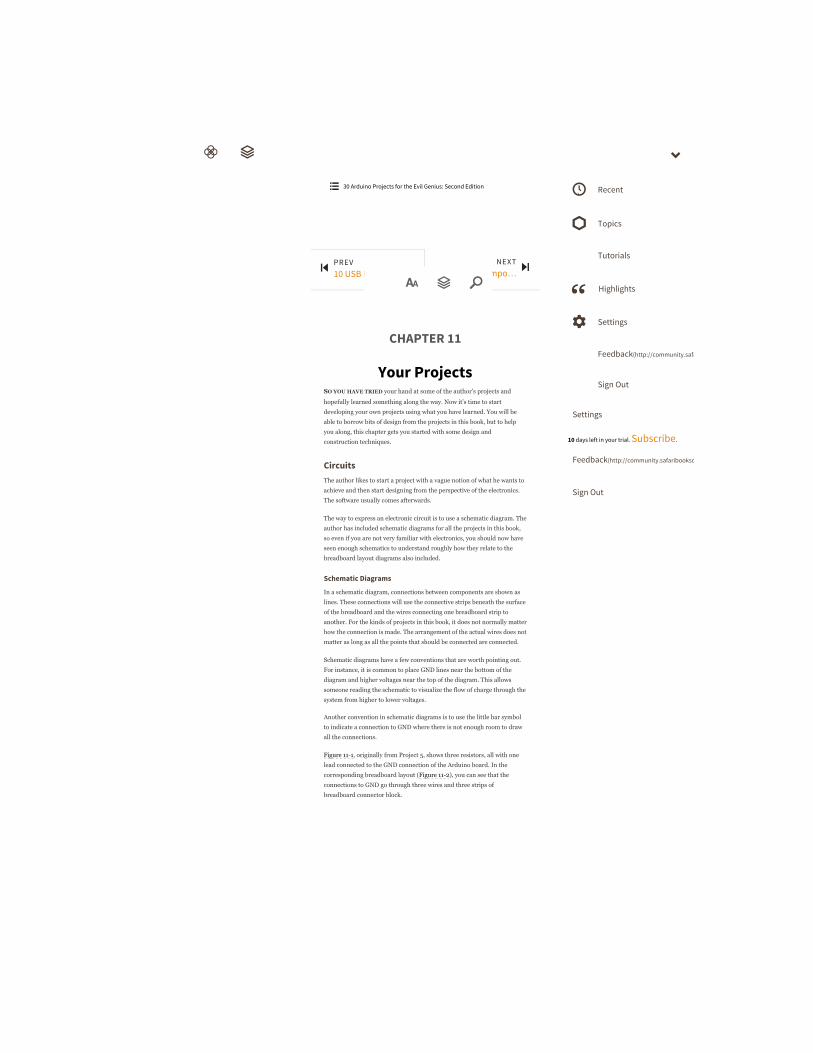
CHAPTER 11
Your ProjectsSO YOU HAVE TRIED your hand at some of the author’s projects and
hopefully learned something along the way. Now it’s time to start
developing your own projects using what you have learned. You will be
able to borrow bits of design from the projects in this book, but to help
you along, this chapter gets you started with some design and
construction techniques.
CircuitsThe author likes to start a project with a vague notion of what he wants to
achieve and then start designing from the perspective of the electronics.
The software usually comes afterwards.
The way to express an electronic circuit is to use a schematic diagram. The
author has included schematic diagrams for all the projects in this book,
so even if you are not very familiar with electronics, you should now have
seen enough schematics to understand roughly how they relate to the
breadboard layout diagrams also included.
Schematic Diagrams
In a schematic diagram, connections between components are shown as
lines. These connections will use the connective strips beneath the surface
of the breadboard and the wires connecting one breadboard strip to
another. For the kinds of projects in this book, it does not normally matter
how the connection is made. The arrangement of the actual wires does not
matter as long as all the points that should be connected are connected.
Schematic diagrams have a few conventions that are worth pointing out.
For instance, it is common to place GND lines near the bottom of the
diagram and higher voltages near the top of the diagram. This allows
someone reading the schematic to visualize the flow of charge through the
system from higher to lower voltages.
Another convention in schematic diagrams is to use the little bar symbol
to indicate a connection to GND where there is not enough room to draw
all the connections.
Figure 111, originally from Project 5, shows three resistors, all with one
lead connected to the GND connection of the Arduino board. In the
corresponding breadboard layout (Figure 112), you can see that the
connections to GND go through three wires and three strips of
breadboard connector block.
PREV10 USB Projects w…
NEXTAppendix: Compo…
ὐ
30 Arduino Projects for the Evil Genius: Second Edition Recent
Topics
Tutorials
Highlights
Settings
Feedback(http://community.safaribooksonline.com)
Sign Out
Settings
10 days left in your trial. Subscribe.
Feedback(http://community.safaribooksonline.com/)
Sign Out
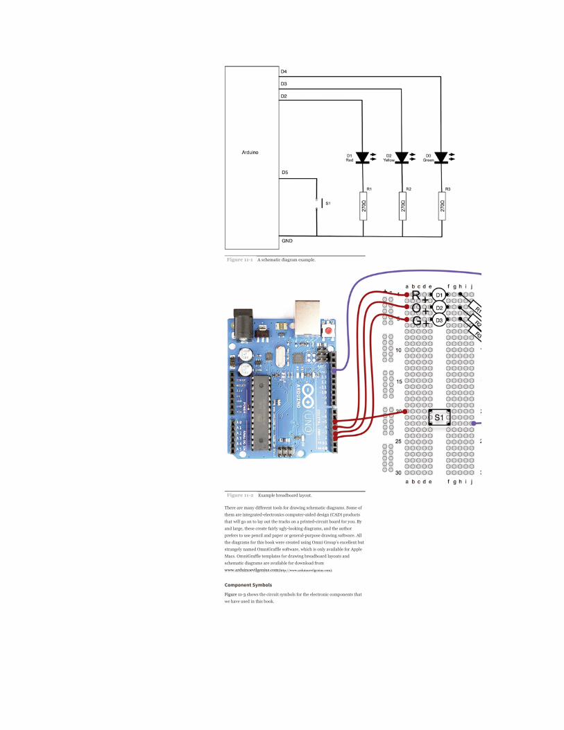
Figure 111 A schematic diagram example.
Figure 112 Example breadboard layout.
There are many different tools for drawing schematic diagrams. Some of
them are integratedelectronics computeraided design (CAD) products
that will go on to lay out the tracks on a printedcircuit board for you. By
and large, these create fairly uglylooking diagrams, and the author
prefers to use pencil and paper or generalpurpose drawing software. All
the diagrams for this book were created using Omni Group’s excellent but
strangely named OmniGraffle software, which is only available for Apple
Macs. OmniGraffle templates for drawing breadboard layouts and
schematic diagrams are available for download from
www.arduinoevilgenius.com(http://www.arduinoevilgenius.com).
Component Symbols
Figure 113 shows the circuit symbols for the electronic components that
we have used in this book.

Figure 113 Circuit symbols.
There are various different standards for circuit diagrams, but the basic
symbols are all recognizable between standards. The set used in this book
does not closely follow any particular standard. I have just chosen what I
consider to be the most easytoread approach to the diagrams.
ComponentsIn this section we look at the practical aspects of components: what they
do and how to identify, choose, and use them.
Datasheets
All component manufacturers produce datasheets for their products.
These act as a specification for how the component will behave. They are
not of much interest for resistors and capacitors but are much more useful
for semiconductors and transistors and especially integrated circuits.
They will often include application notes that include example schematics
for using the components.
These are all available on the Internet. However, if you search for “BC158
datasheet” in your favorite search engine, you will find that many of the
top hits are for organizations cashing in on the fact that people search for
datasheets a lot. These organizations surround the datasheets with
pointless advertising and pretend that they add some value to looking up
datasheets by subscribing to their service. These websites usually just lead
to a frustration of clicking and should be ignored in favor of any
manufacturers’ websites. So scan through the search results until you see
a URL such as www.fairchild.com(http://www.fairchild.com).
Alternatively, many of the component retail suppliers such as Farnell
provide freeofcharge datasheets for practically every component they
sell, which is to be much applauded. This also means that you can
compare prices and buy the components while you are finding out about
them.
Resistors
Resistors are the most common and cheapest electronic components
around. Their most common uses are
To prevent excessive current flowing (see any project that uses an
LED)
In a pair or as a variable resistor to divide a voltage
Chapter 2 explained Ohm’s law and used it to decide on a value of a series
resistor for an LED. Similarly, in Project 19 we reduced the signal from
our resistor ladder using two resistors as a potential divider.
Resistors have colored bands around them to indicate their value.
However, if you are unsure of a resistor, you can always find its resistance
using a multimeter. Once you get the hang of it, it’s easy to read the values
using the colored bands.
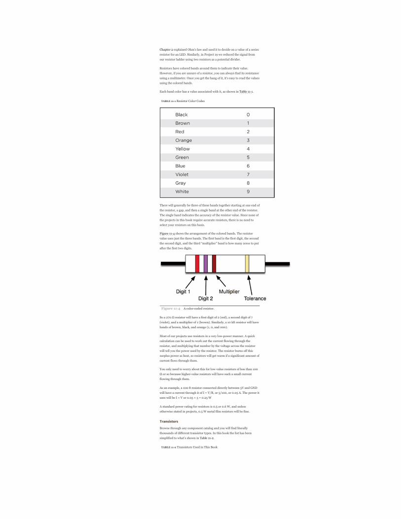
Each band color has a value associated with it, as shown in Table 111.
TABLE 111 Resistor Color Codes
There will generally be three of these bands together starting at one end of
the resistor, a gap, and then a single band at the other end of the resistor.
The single band indicates the accuracy of the resistor value. Since none of
the projects in this book require accurate resistors, there is no need to
select your resistors on this basis.
Figure 114 shows the arrangement of the colored bands. The resistor
value uses just the three bands. The first band is the first digit, the second
the second digit, and the third “multiplier” band is how many zeros to put
after the first two digits.
Figure 114 A colorcoded resistor.
So a 270 Ω resistor will have a first digit of 2 (red), a second digit of 7
(violet), and a multiplier of 1 (brown). Similarly, a 10 kft resistor will have
bands of brown, black, and orange (1, 0, and 000).
Most of our projects use resistors in a very lowpower manner. A quick
calculation can be used to work out the current flowing through the
resistor, and multiplying that number by the voltage across the resistor
will tell you the power used by the resistor. The resistor burns off this
surplus power as heat, so resistors will get warm if a significant amount of
current flows through them.
You only need to worry about this for lowvalue resistors of less than 100
Ω or so because highervalue resistors will have such a small current
flowing through them.
As an example, a 100 ft resistor connected directly between 5V and GND
will have a current through it of I = V/R, or 5/100, or 0.05 A. The power it
uses will be I × V or 0.05 × 5 = 0.25 W
A standard power rating for resistors is 0.5 or 0.6 W, and unless
otherwise stated in projects, 0.5 W metal film resistors will be fine.
Transistors
Browse through any component catalog and you will find literally
thousands of different transistor types. In this book the list has been
simplified to what’s shown in Table 112.
TABLE 112 Transistors Used in This Book
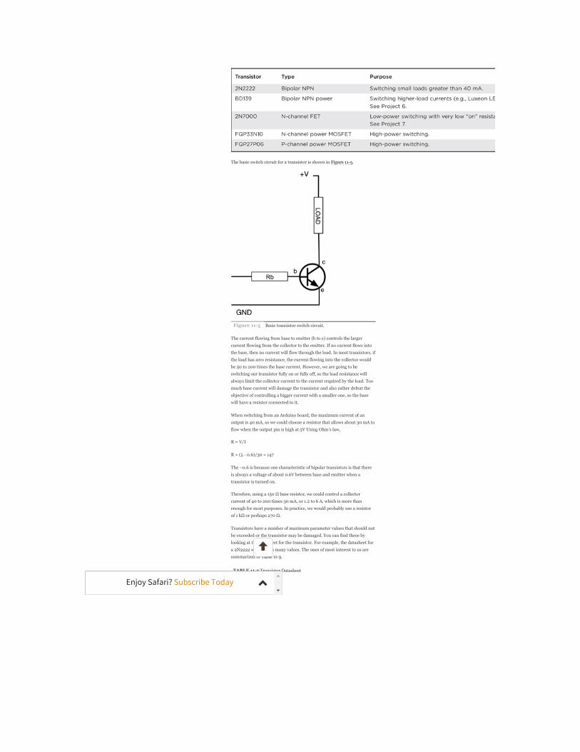
The basic switch circuit for a transistor is shown in Figure 115.
Figure 115 Basic transistor switch circuit.
The current flowing from base to emitter (b to e) controls the larger
current flowing from the collector to the emitter. If no current flows into
the base, then no current will flow through the load. In most transistors, if
the load has zero resistance, the current flowing into the collector would
be 50 to 200 times the base current. However, we are going to be
switching our transistor fully on or fully off, so the load resistance will
always limit the collector current to the current required by the load. Too
much base current will damage the transistor and also rather defeat the
objective of controlling a bigger current with a smaller one, so the base
will have a resistor connected to it.
When switching from an Arduino board, the maximum current of an
output is 40 mA, so we could choose a resistor that allows about 30 mA to
flow when the output pin is high at 5V Using Ohm’s law,
R = V/I
R = (5 0.6)/30 = 147
The –0.6 is because one characteristic of bipolar transistors is that there
is always a voltage of about 0.6V between base and emitter when a
transistor is turned on.
Therefore, using a 150 Ω base resistor, we could control a collector
current of 40 to 200 times 30 mA, or 1.2 to 6 A, which is more than
enough for most purposes. In practice, we would probably use a resistor
of 1 kΩ or perhaps 270 Ω.
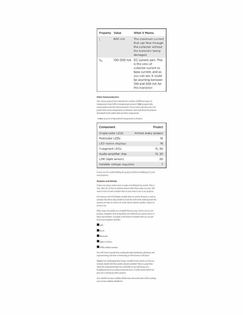
Transistors have a number of maximum parameter values that should not
be exceeded or the transistor may be damaged. You can find these by
looking at the datasheet for the transistor. For example, the datasheet for
a 2N2222 will contain many values. The ones of most interest to us are
summarized in Table 113.
TABLE 113 Transistor Datasheet
Enjoy Safari? Subscribe Today
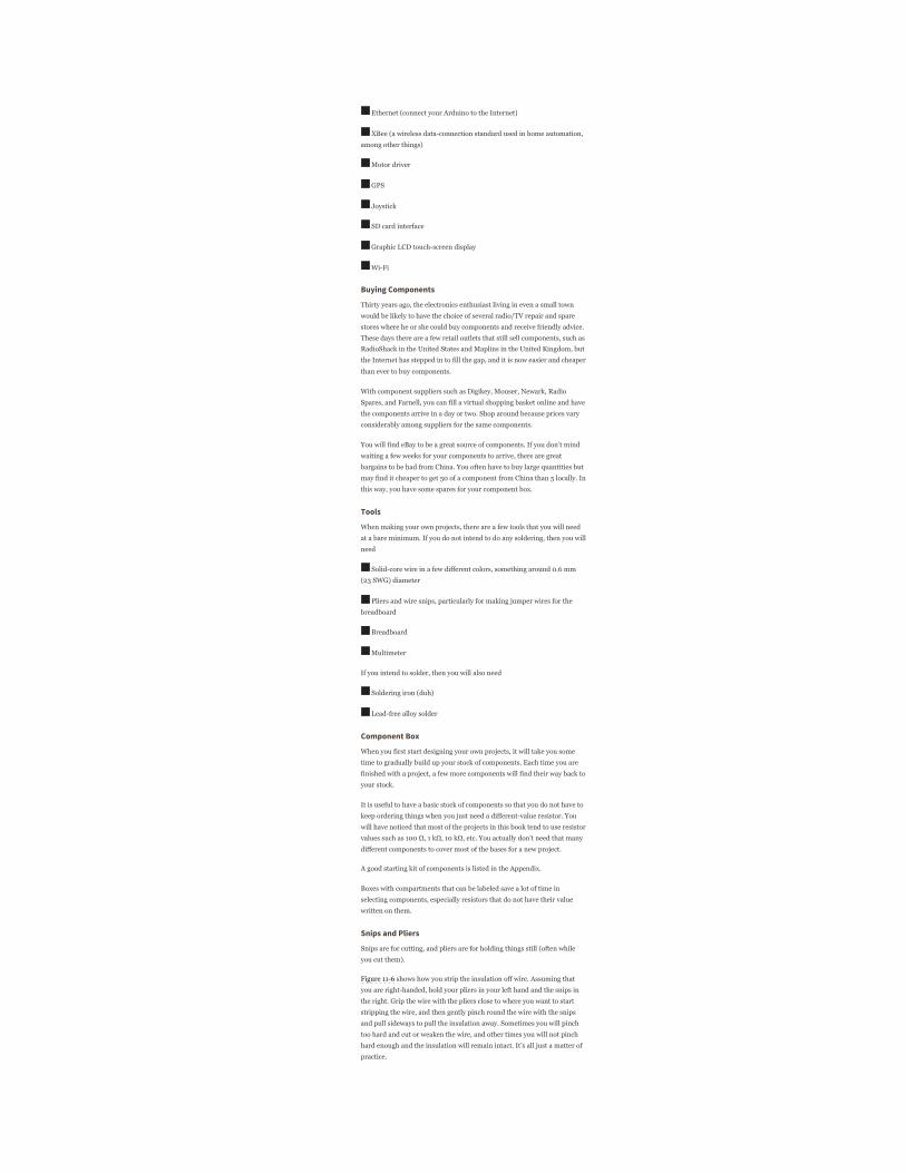
Other Semiconductors
The various projects have introduced a number of different types of
components, from LEDs to temperature sensors; Table 114 provides
some pointers into the various projects. If you want to develop your own
project that senses temperature or whatever, first read about the projects
developed by the author that use these components.
TABLE 104 Use of Specialized Components in Projects
It may even be worth building the project and then modifying it to your
own purposes.
Modules and Shields
It does not always make sense to make everything from scratch. This is
why, after all, we buy an Arduino board rather than make our own. The
same is true of some modules that we may want to use in our projects.
For instance, the LCD display module that we used in Projects 17 and 22
contains the driver chip needed to work the LCD itself, reducing both the
amount of work we need to do in the sketch and the number of pins we
need to use.
Other types of modules are available that you may wish to use in your
projects. Suppliers such as Sparkfun and Adafruit are a great source of
ideas and modules. A sample of the kinds of modules that you can get
from such suppliers includes
GPS
WiFi
Bluetooth
Zigbee wireless
GPRS cellular modem
You will need to spend time reading through datasheets, planning, and
experimenting, but that is what being an Evil Genius is all about.
Slightly less challenging than using a module from scratch is to buy an
Arduino shield with the module already installed. This is a good idea
when the components that you would like to use will not go on a
breadboard (such as surfacemount devices). A readymade shield can
give you a real leg up with a project.
New shields become available all the time, but at the time of this writing,
you can buy Arduino shields for
Ethernet (connect your Arduino to the Internet)
XBee (a wireless dataconnection standard used in home automation,
among other things)
Motor driver
GPS
Joystick
SD card interface
Graphic LCD touchscreen display
WiFi
Buying Components
Thirty years ago, the electronics enthusiast living in even a small town
would be likely to have the choice of several radio/TV repair and spare
stores where he or she could buy components and receive friendly advice.
These days there are a few retail outlets that still sell components, such asRadioShack in the United States and Maplins in the United Kingdom, but
the Internet has stepped in to fill the gap, and it is now easier and cheaper
than ever to buy components.
With component suppliers such as Digikey, Mouser, Newark, Radio
Spares, and Farnell, you can fill a virtual shopping basket online and have
the components arrive in a day or two. Shop around because prices vary
considerably among suppliers for the same components.
You will find eBay to be a great source of components. If you don’t mind
waiting a few weeks for your components to arrive, there are great
bargains to be had from China. You often have to buy large quantities but
may find it cheaper to get 50 of a component from China than 5 locally. In
this way, you have some spares for your component box.
Tools
When making your own projects, there are a few tools that you will need
at a bare minimum. If you do not intend to do any soldering, then you will
need
Solidcore wire in a few different colors, something around 0.6 mm
(23 SWG) diameter
Pliers and wire snips, particularly for making jumper wires for the
breadboard
Breadboard
Multimeter
If you intend to solder, then you will also need
Soldering iron (duh)
Leadfree alloy solder
Component Box
When you first start designing your own projects, it will take you some
time to gradually build up your stock of components. Each time you are
finished with a project, a few more components will find their way back to
your stock.
It is useful to have a basic stock of components so that you do not have to
keep ordering things when you just need a differentvalue resistor. You
will have noticed that most of the projects in this book tend to use resistor
values such as 100 Ω, 1 kΩ, 10 kΩ, etc. You actually don’t need that many
different components to cover most of the bases for a new project.
A good starting kit of components is listed in the Appendix.
Boxes with compartments that can be labeled save a lot of time in
selecting components, especially resistors that do not have their value
written on them.
Snips and Pliers
Snips are for cutting, and pliers are for holding things still (often while
you cut them).
Figure 116 shows how you strip the insulation off wire. Assuming that
you are righthanded, hold your pliers in your left hand and the snips in
the right. Grip the wire with the pliers close to where you want to start
stripping the wire, and then gently pinch round the wire with the snips
and pull sideways to pull the insulation away. Sometimes you will pinch
too hard and cut or weaken the wire, and other times you will not pinch
hard enough and the insulation will remain intact. It’s all just a matter of
practice.
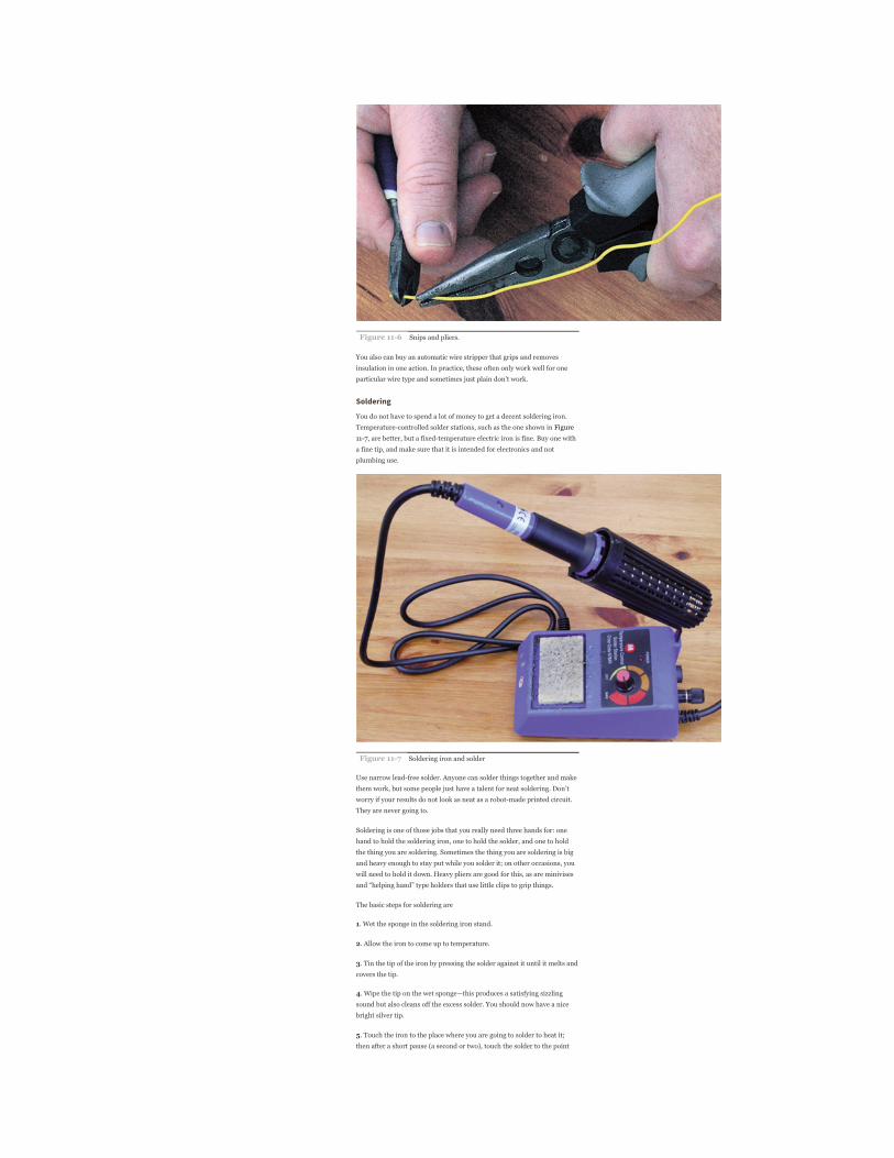
Figure 116 Snips and pliers.
You also can buy an automatic wire stripper that grips and removes
insulation in one action. In practice, these often only work well for one
particular wire type and sometimes just plain don’t work.
Soldering
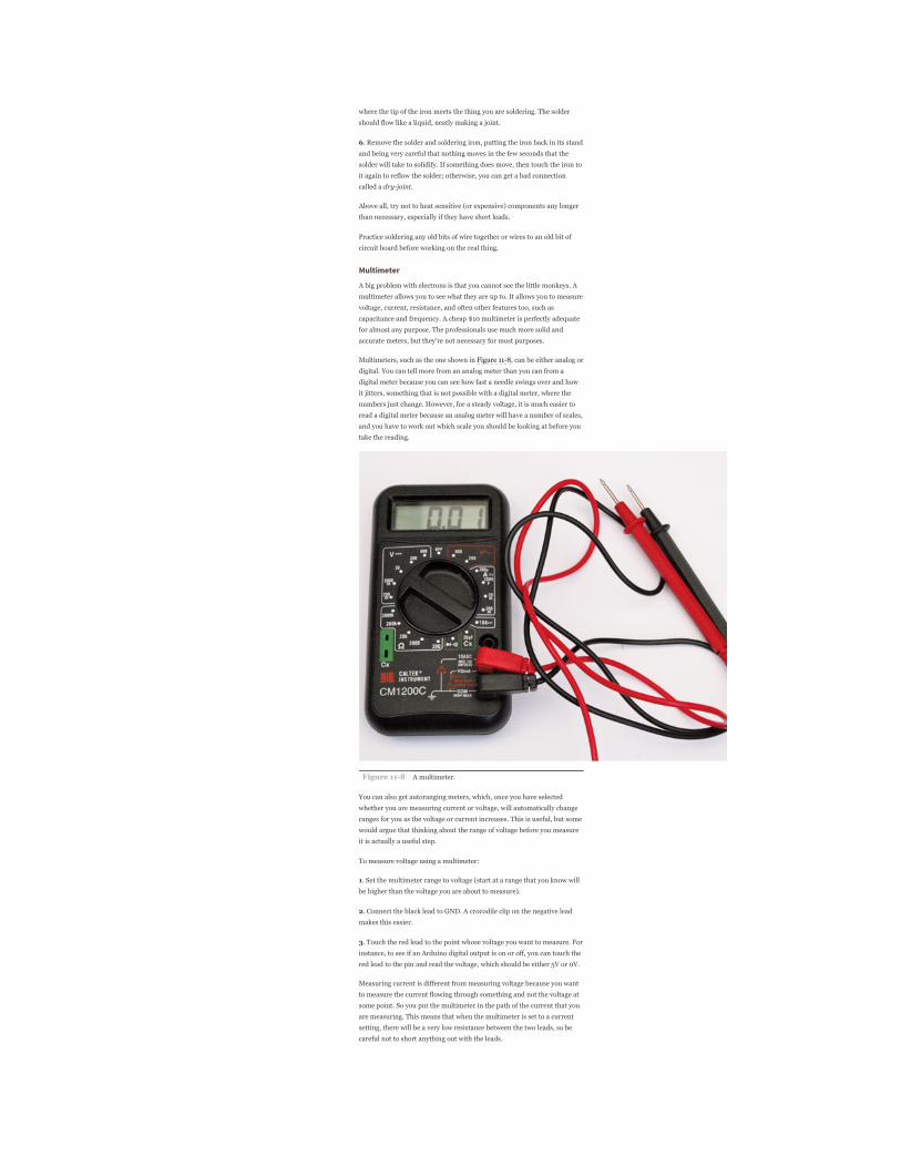
You do not have to spend a lot of money to get a decent soldering iron.
Temperaturecontrolled solder stations, such as the one shown in Figure
117, are better, but a fixedtemperature electric iron is fine. Buy one with
a fine tip, and make sure that it is intended for electronics and not
plumbing use.
Figure 117 Soldering iron and solder
Use narrow leadfree solder. Anyone can solder things together and make
them work, but some people just have a talent for neat soldering. Don’t
worry if your results do not look as neat as a robotmade printed circuit.
They are never going to.
Soldering is one of those jobs that you really need three hands for: one
hand to hold the soldering iron, one to hold the solder, and one to hold
the thing you are soldering. Sometimes the thing you are soldering is big
and heavy enough to stay put while you solder it; on other occasions, you
will need to hold it down. Heavy pliers are good for this, as are minivises
and “helping hand” type holders that use little clips to grip things.
The basic steps for soldering are
1. Wet the sponge in the soldering iron stand.
2. Allow the iron to come up to temperature.
3. Tin the tip of the iron by pressing the solder against it until it melts andcovers the tip.
4. Wipe the tip on the wet sponge—this produces a satisfying sizzling
sound but also cleans off the excess solder. You should now have a nice
bright silver tip.
5. Touch the iron to the place where you are going to solder to heat it;then after a short pause (a second or two), touch the solder to the point
where the tip of the iron meets the thing you are soldering. The solder
should flow like a liquid, neatly making a joint.
6. Remove the solder and soldering iron, putting the iron back in its standand being very careful that nothing moves in the few seconds that the
solder will take to solidify. If something does move, then touch the iron to
it again to reflow the solder; otherwise, you can get a bad connection
called a dryjoint.
Above all, try not to heat sensitive (or expensive) components any longer
than necessary, especially if they have short leads.
Practice soldering any old bits of wire together or wires to an old bit of
circuit board before working on the real thing.
Multimeter
A big problem with electrons is that you cannot see the little monkeys. A
multimeter allows you to see what they are up to. It allows you to measure
voltage, current, resistance, and often other features too, such as
capacitance and frequency. A cheap $10 multimeter is perfectly adequate
for almost any purpose. The professionals use much more solid and
accurate meters, but they’re not necessary for most purposes.
Multimeters, such as the one shown in Figure 118, can be either analog or
digital. You can tell more from an analog meter than you can from a
digital meter because you can see how fast a needle swings over and how
it jitters, something that is not possible with a digital meter, where the
numbers just change. However, for a steady voltage, it is much easier to
read a digital meter because an analog meter will have a number of scales,
and you have to work out which scale you should be looking at before you
take the reading.
Figure 118 A multimeter.
You can also get autoranging meters, which, once you have selected
whether you are measuring current or voltage, will automatically change
ranges for you as the voltage or current increases. This is useful, but some
would argue that thinking about the range of voltage before you measure
it is actually a useful step.
To measure voltage using a multimeter:
1. Set the multimeter range to voltage (start at a range that you know willbe higher than the voltage you are about to measure).
2. Connect the black lead to GND. A crocodile clip on the negative leadmakes this easier.
3. Touch the red lead to the point whose voltage you want to measure. Forinstance, to see if an Arduino digital output is on or off, you can touch the
red lead to the pin and read the voltage, which should be either 5V or 0V.
Measuring current is different from measuring voltage because you want
to measure the current flowing through something and not the voltage at
some point. So you put the multimeter in the path of the current that you
are measuring. This means that when the multimeter is set to a current
setting, there will be a very low resistance between the two leads, so be
careful not to short anything out with the leads.

Figure 119 shows how you could measure the current flowing through an
LED.
Figure 119 Measuring current.
To measure current:
1. Set the multimeter range to a current range higher than the expectedcurrent. Note that multimeters often have a separate highcurrent
connector for currents as high as 10 A.
2. Connect the positive lead of the meter to the more positive side fromwhich the current will flow.
3. Connect the negative lead of the meter to the more negative side. Notethat if you get this the wrong way round, a digital meter will just indicate a
negative current; however, connecting an analog meter the wrong way
round may damage it.
4. In the case of an LED, the LED should still light as brightly as beforeyou put the meter into the circuit, and you will be able to read the current
consumption.
Another feature of a multimeter that is sometimes useful is the continuity
test feature. This will usually beep when the two test leads are connected
together. You can use this to test fuses, etc., as well as to test for
accidental short circuits on a circuit board or broken connections in a
wire.
Resistance measurement is occasionally useful, particularly if you want to
determine the resistance of an unmarked resistor.
Some meters also have diode and transistor test connections, which can
be useful to find and discard transistors that have burned out.
Oscilloscope
In Project 18 we built a simple oscilloscope. An oscilloscope is an
indispensable tool for any kind of electronics design or test where you are
looking at a signal that changes over time. Oscilloscopes are relatively
expensive, and there are various types. One of the most costeffective
types is similar in concept to the one in Project 18. That oscilloscope just
sends its readings across to a computer that is responsible for displaying
them.
Entire books have been written about using an oscilloscope effectively,
and every oscilloscope is different, so we will just cover the basics here.
As you can see from Figure 1110, the screen showing the waveform is
displayed over the top of a grid. The vertical grid is in units of some
fraction of volts, which on this screen is 2V per division. So the voltage of
the square wave in total is 2.5 × 2 = 5V.
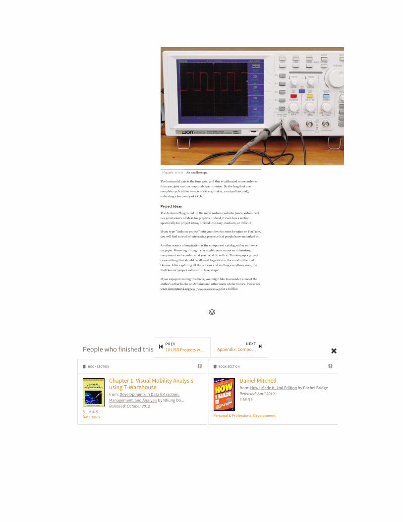
Figure 1110 An oscilloscope.
The horizontal axis is the time axis, and this is calibrated in seconds—in
this case, 500 ms (microseconds) per division. So the length of one
complete cycle of the wave is 1000 ms, that is, 1 ms (millisecond),
indicating a frequency of 1 kHz.
Project Ideas
The Arduino Playground on the main Arduino website (www.arduino.cc)
is a great source of ideas for projects. Indeed, it even has a section
specifically for project ideas, divided into easy, medium, or difficult.
If you type “Arduino project” into your favorite search engine or YouTube,
you will find no end of interesting projects that people have embarked on.
Another source of inspiration is the component catalog, either online or
on paper. Browsing through, you might come across an interesting
component and wonder what you could do with it. Thinking up a project
is something that should be allowed to gestate in the mind of the Evil
Genius. After exploring all the options and mulling everything over, the
Evil Genius’ project will start to take shape!
If you enjoyed reading this book, you might like to consider some of the
author’s other books on Arduino and other areas of electronics. Please see
www.simonmonk.org(http://www.simonmonk.org) for a full list.
People who finished this also enjoyed:
Chapter 1: Visual Mobility Analysisusing T-Warehousefrom: Developments in Data Extraction,Management, and Analysis by Nhung Do...Released: October 2012
51 MINSDatabases
BOOK SECTIONὍ
Daniel Mitchellfrom: How I Made It, 2nd Edition by Rachel BridgeReleased: April 20106 MINS
Personal & Professional Development
BOOK SECTIONὍ
PREV10 USB Projects w…
NEXTAppendix: Compo…

Recommended / Queue / Recent / Topics / Tutorials / Settings / Blog(http://blog.safaribooksonline.com) /Feedback(http://community.safaribooksonline.com/) / Sign Out© 2015 Safari(http://www.safaribooksonline.com/). Terms of Service / Privacy Policy
Retrieving Informationfrom: Programming ColdFusion MX, 2nd Edition byRob Brooks-BilsonReleased: August 200322 MINS
Certification / Design / Digital Media / Web Development
BOOK SECTIONὍ
INTRODUCTIONfrom: My Steam Engine is Broken by JonathanGifford...Released: December 201421 MINS
Personal & Professional Development
BOOK SECTIONὍ
Chapter 6 Post-Production/ImageManipulationfrom: The VES Handbook of Visual Effects, 2ndEdition by Susan Zwerman...Released: July 2014
284 MINSDigital Media
BOOK SECTIONὍ
Introductionfrom: Adventures in Arduino by Becky StewartReleased: May 201536 MINS
DIY & Hardware
BOOK SECTIONὍ
Introduction: What Is Coding andWhy Is It Good for Your Kids?from: Teach Your Kids to Code by Bryson PayneReleased: April 20157 MINS
Core Programming
BOOK SECTIONὍ
Chapter 3: Emotional IntelligenceModel for Managers in TurkishBanking Sector and an Applicationfrom: Handbook of Research on StrategicDevelopments and Regulatory Practice in Global
Finance by Ümit Hacıoğlu...Released: November 201453 MINSBusiness
BOOK SECTIONὍ
Trust Trumps Transactionsfrom: The Ultimate Startup Guide to OutboundSales by Steli EftiReleased: March 20155 MINS
Business / Business Communication /Personal & Professional Development
BOOK SECTIONὍ
Coding in FSO Channelsfrom: Terrestrial Wireless Optical Communicationby Devi ChadhaReleased: March 201359 MINS
Engineering
BOOK SECTIONὍ