Embed Size (px)
DESCRIPTION
11 T Dipole Experience. M. Karppinen CERN TE-MSC On behalf of CERN-FNAL project teams. The HiLumi LHC Design Study (a sub-system of HL-LHC) is co-funded by the European Commission within the Framework Programme 7 Capacities Specific Programme , Grant Agreement 284404. . - PowerPoint PPT Presentation
Citation preview
11 T Dipole Experience
M. Karppinen CERN TE-MSCOn behalf of CERN-FNAL project teams
The HiLumi LHC Design Study (a sub-system of HL-LHC) is co-funded by the European Commission within the Framework Programme 7 Capacities Specific Programme, Grant
Agreement 284404.

11 T Nb3Sn
11 T Dipole for DS Upgrade
Create space for additional collimators by replacing 8.33 T MB with 11 T Nb3Sn dipoles compatible with LHC lattice and main systems.
119 Tm @ 11.85 kA (in series with MB) LS2 : IR-2
o 2 MB => 4 x 5.5 m CM + spares LS3 : IR-1,5 and Point-3,7
o 4 x 4 MB => 32 x 5.5 m CM + spares
180 x 5.5-m-long Nb3Sn coils
M. Karppinen CERN TE-MSC
Joint development program between CERN and FNAL underway since Oct-2010.
MB.B8R/L
MB.B11R/L
5.5 m Nb3Sn 5.5 m Nb3Sn0.8 m Collim.
15,66 m (IC to IC plane)
14 February 2014

11 T Dipole Design Features
14 February 2014 M. Karppinen CERN TE-MSC
11.25 T at 11.85 kA with 20% margin at 1.9 K 60 mm bore and straight 5.5-m-long coldmass 6-block coil design, 2 layers, 56 turns (IL 22, OL 34), no
internal splice Separate collared coils, 2-in-1 laminated iron yoke with
vertical split, welded stainless steel outer shell
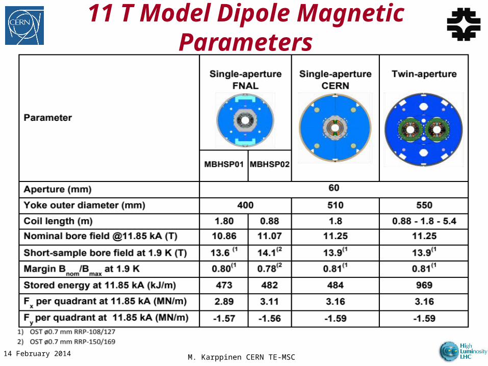
11 T Model Dipole Magnetic Parameters
14 February 2014 M. Karppinen CERN TE-MSC

M. Karppinen CERN TE-MSC
Mechanical Design Concepts
14 February 2014
CERN FNAL
Pole loading design Integrated pole design
Pole wedge
Shim
Fillerwedge
Loading plate• Coil stress <150 MPa
at all times up to 12 T design field
• Yoke gap closed at RT and remain closed up to 12 T

M. Karppinen CERN TE-MSC
CERN 11 T Dipole Coil
14 February 2014
Loading plate2 mm 316LN
SLS (Selective Laser Sintering) End Spacerswith “springy legs”
Braided 11-TEX S2-glasson “open-C” Mica sleeve
ODS (Oxide Dispersion Strengthened) Cu-alloy Wedges
Cour
tesy
of D
. Mitc
hell,
FNA
L
OST RRP-108/127
14.85
Ø0.7
M. Karppinen CERN TE-MSC
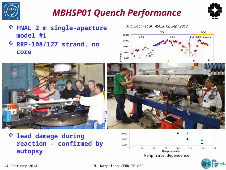
FNAL 2 m single-aperture model #1
RRP-108/127 strand, no core
Bmax=10.4 T at 1.9 K and 50 A/s (78% of SSL)
long training irregular ramp rate
dependence Conductor degradation in
coil OL mid-plane blocks and leads
lead damage during reaction - confirmed by autopsy
MBHSP01 Quench Performance
14 February 2014
A.V. Zlobin et al., ASC2012, Sept 2012
Quench history
Ramp rate dependence

M. Karppinen CERN TE-MSC
FNAL 1 m single aperture model #2
RRP-150/169 strand, 25 µm SS core
Improved quench performanceo Bmax= 11.7 T – 97.5% of design
field B=12 T (78% of SSL at 1.9 K)
Field quality meets the present requirements
Issues to be addressedo Long trainingo Steady state B0 = 10.5..10.7 T
@1.9Ko Origin of conductor degradation
in OL mid-plane blocks in coil fabrication or assembly process?
MBHSP02 Quench Performance
14 February 2014
Magnet training
Ramp rate dependence
Courtesy of G. Chlachidze, FNAL

M. Karppinen CERN TE-MSC
MBHSM01 Mirror Magnet
14 February 2014
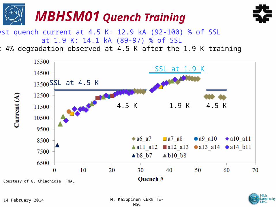
MBHSM01 Quench Training
M. Karppinen CERN TE-MSC14 February 2014
Highest quench current at 4.5 K: 12.9 kA (92-100) % of SSL at 1.9 K: 14.1 kA (89-97) % of SSL
About 4% degradation observed at 4.5 K after the 1.9 K training
SSL at 4.5 KSSL at 1.9 K
4.5 K 4.5 K1.9 K
Courtesy of G. Chlachidze, FNAL

M. Karppinen CERN TE-MSC
Lessons: Coil Parts Nb3Sn Rutherford cable
o Stainless steel core reduces eddy current effectso Limited compaction reduces mechanical stabilityo Winding tooling and process developmento Braiding S2-glass over Mica-sleeve works well
End partso SLS cost effective, flexible, and fast way of producing
fully functional partso 3-5 iterations required to get the shapes right, all manual
modifications shall be minimisedo Rigid metallic parts need features to make the “legs”
flexible (“springy legs”, “accordeon”,..)o Dielectric coatings to develop: reactor paint, sputtering,
plasma coating, ..o Epoxy-glass saddles (electrical insulation, softer for cable
tails/splice, axial loading) ODS wedges to minimise plastic deformation and distortion
of the coil geometry14 February 2014

M. Karppinen CERN TE-MSC
Min 3 Practice coils: Cu-cable, 2 X Nb3Sn Mirror test to qualify coil technology Tooling design
o Modular tooling for easy scale-upo Understand (= measure) coil dimensional changeso Tight manufacturing tolerances require high
precision quality controlo Material selection and heat treatments (reaction
tool) o First design the impregnation tool then reaction tool
Coil inspection:o E-modulus risky to measureo High modulus (wrt. Nb-Ti) means tight tolerances
and require accurate dimensional control with CMMo Assembly parameter definition based on CMM data
can be tricky..
Lessons: Coil Fabrication
14 February 2014
M. Karppinen CERN TE-MSC
To Develop: Heaters & Splicing Outer layer heaters
o Heaters and V-tap wiring integrated in polymide sandwich (“trace”) made as PCB
o may not be enough to guarantee safe operation with redundancy
o Inner layer “trace” difficult to bond reliably Inter-layer heaters
o Very efficient heat transfer to coilso Reaction resistant glass-Mica-St.St-Mica-glass
sandwicho “Conventional” heaters with I-L splice
Inter-layer splice (within the coil i.e. high field)o Bring inner layer lead radially out and spliceo Nb3Sn bridge (MSUT concept)o HTS bridge
14 February 2014