Embed Size (px)
Citation preview
2
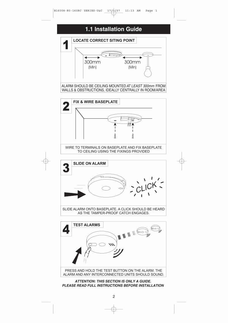
1.1 Installation Guide
B16008-R0-160RC SERIES-U&C 17/1/07 11:13 AM Page 1
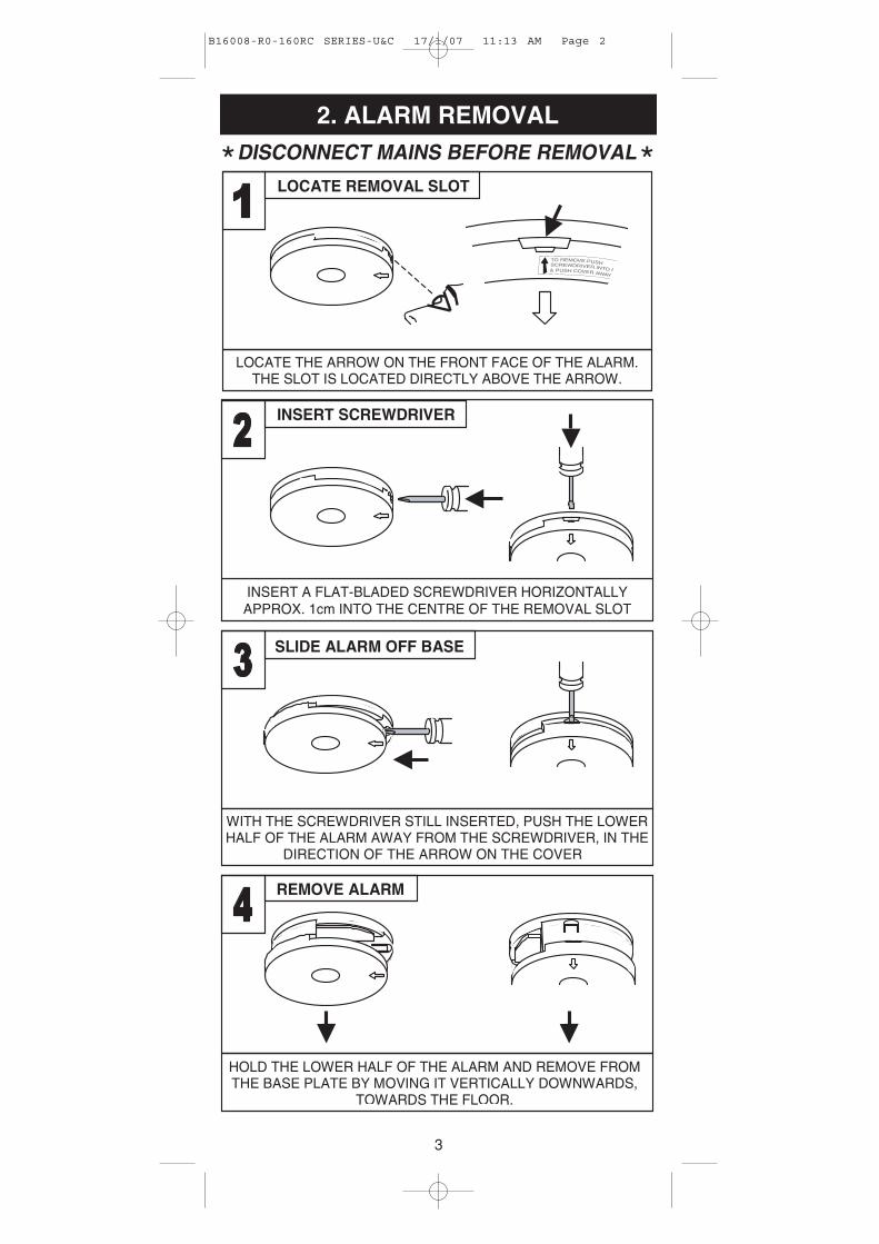
2. ALARM REMOVAL
SLIDE ALARM OFF BASE
WITH THE SCREWDRIVER STILL INSERTED, PUSH THE LOWER HALF OF THE ALARM AWAY FROM THE SCREWDRIVER, IN THE
DIRECTION OF THE ARROW ON THE COVER
HOLD THE LOWER HALF OF THE ALARM AND REMOVE FROMTHE BASE PLATE BY MOVING IT VERTICALLY DOWNWARDS,
TOWARDS THE FLOOR.
REMOVE ALARM
LOCATE REMOVAL SLOT
LOCATE THE ARROW ON THE FRONT FACE OF THE ALARM. THE SLOT IS LOCATED DIRECTLY ABOVE THE ARROW.
INSERT SCREWDRIVER
INSERT A FLAT-BLADED SCREWDRIVER HORIZONTALLYAPPROX. 1cm INTO THE CENTRE OF THE REMOVAL SLOT
TO REMOVE PUSH
& PUSH COVER AWAY
SCREWDRIVER INTO SLOT
3
B16008-R0-160RC SERIES-U&C 17/1/07 11:13 AM Page 2
2. HOW MANY ALARMS TO INSTALL- CATEGORIES & GRADES -
The advice here follows the guidance in British StandardBS 5839-Part 6: 2004 in general (for further information seethe BS standard itself).
The main reason for fitting Smoke & Heat Alarms in dwellingsis to ensure that when there is a fire, sufficient early warningis given so that everybody can escape safely.
This means that the fire alarms should ideally be located nearall potential sources of fires and that the alarm should beheard throughout the house – particularly in the bedrooms.
It is also important that nuisance/false alarms are minimisedto ensure the units are not disabled or ignored.
The BS standard gives guidance on:
- how many alarms to install
- what type of alarm to use
- where to position alarms
The above points will depend on the type of dwelling to beprotected and the level of fire risk.
Fire Risk Assessment
The ‘Grade’ and ‘Category’ of system that should be installeddepends on the fire risk. The risk assessment is based on acombination of probabilities:- fire occurring- injury or death to occupant- system operating correctly with a fire- early detection and warning to occupants in the event of a fire.
The greater the risks, the more comprehensive and reliablesystems are needed.
2.1 Categories of System
There are three Categories of LD systems for Life protectionin Dwellings that can be installed, depending on the fire riskand regulations.
Please see following pages for detailed information.
4
B16008-R0-160RC SERIES-U&C 17/1/07 11:13 AM Page 3
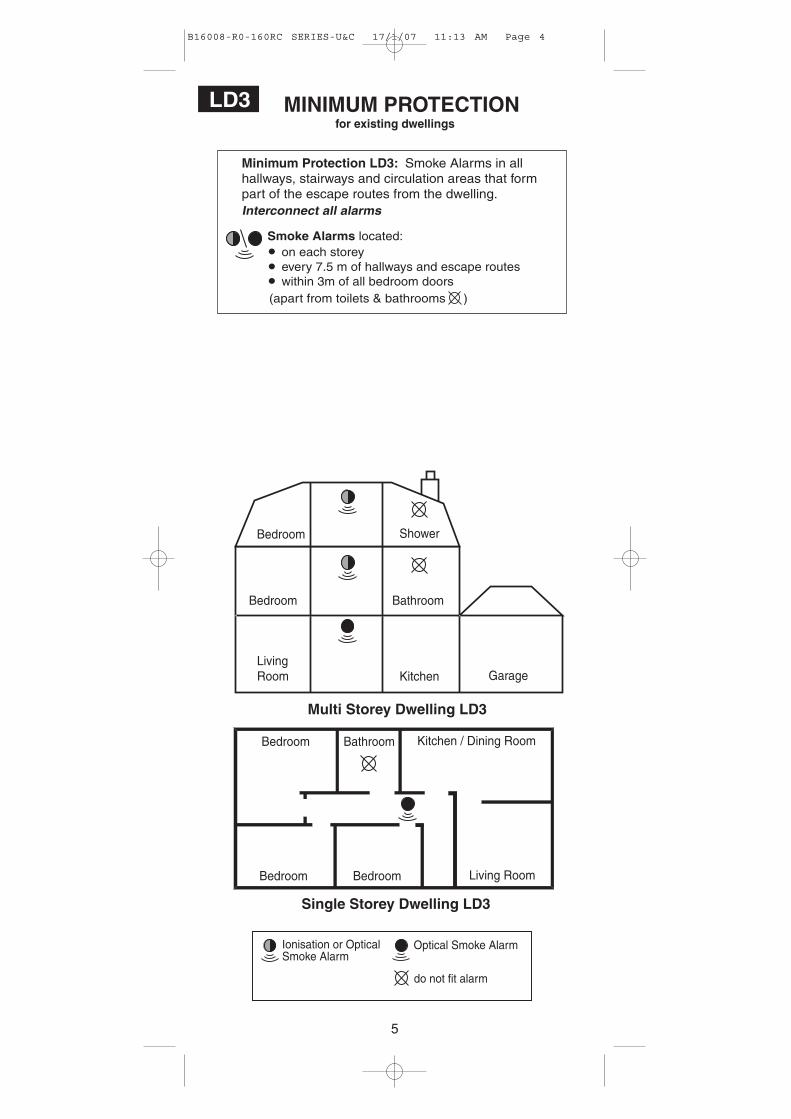
for existing dwellingsMINIMUM PROTECTIONLD3
Minimum Protection LD3: Smoke Alarms in allhallways, stairways and circulation areas that formpart of the escape routes from the dwelling.
Multi Storey Dwelling LD3
LivingRoom
Bedroom Bathroom
Kitchen
Bedroom Shower
Garage
Smoke Alarms located:on each storeyevery 7.5 m of hallways and escape routeswithin 3m of all bedroom doors
(apart from toilets & bathrooms )
Bedroom
Bedroom Bedroom
Kitchen / Dining Room
Living Room
Bathroom
Single Storey Dwelling LD3
do not fit alarm
Ionisation or OpticalSmoke Alarm
Optical Smoke Alarm
5
B16008-R0-160RC SERIES-U&C 17/1/07 11:13 AM Page 4
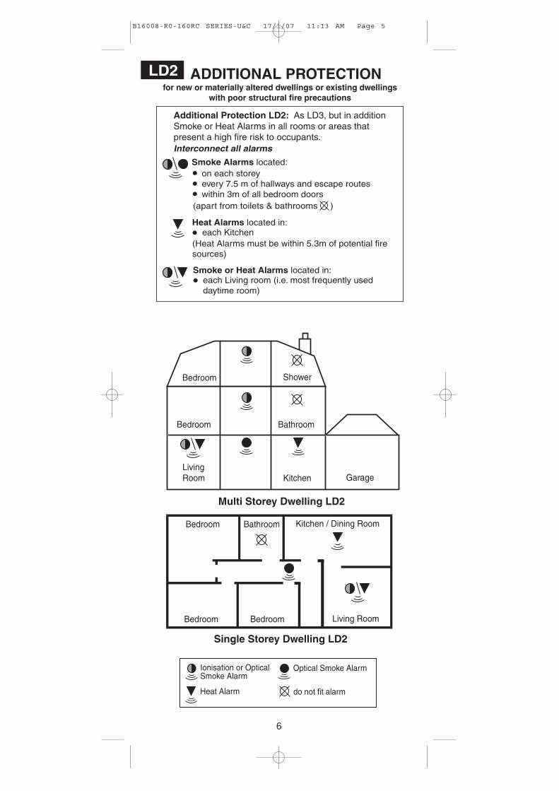
Additional Protection LD2: As LD3, but in additionSmoke or Heat Alarms in all rooms or areas thatpresent a high fire risk to occupants.
Heat Alarms located in:
(Heat Alarms must be within 5.3m of potential firesources)
each Kitchen
Smoke or Heat Alarms located in:each Living room (i.e. most frequently useddaytime room)
Smoke Alarms located:on each storeyevery 7.5 m of hallways and escape routeswithin 3m of all bedroom doors
(apart from toilets & bathrooms )
for new or materially altered dwellings or existing dwellingswith poor structural fire precautions
ADDITIONAL PROTECTIONLD2
Multi Storey Dwelling LD2
LivingRoom
Bedroom Bathroom
Kitchen
Bedroom Shower
Garage
Bedroom
Bedroom Bedroom
Kitchen / Dining Room
Living Room
Bathroom
Single Storey Dwelling LD2
Heat Alarm do not fit alarm
Ionisation or OpticalSmoke Alarm
Optical Smoke Alarm
6
B16008-R0-160RC SERIES-U&C 17/1/07 11:13 AM Page 5
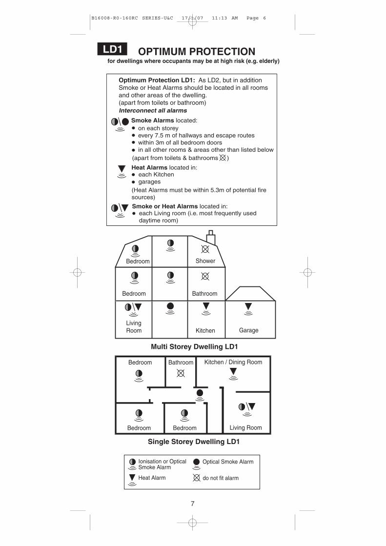
for dwellings where occupants may be at high risk (e.g. elderly)OPTIMUM PROTECTIONLD1
Optimum Protection LD1: As LD2, but in additionSmoke or Heat Alarms should be located in all roomsand other areas of the dwelling.(apart from toilets or bathroom)
Multi Storey Dwelling LD1
Heat Alarms located in:
(Heat Alarms must be within 5.3m of potential firesources)
each Kitchengarages
LivingRoom
Bedroom Bathroom
Kitchen
Bedroom Shower
Garage
Smoke or Heat Alarms located in:each Living room (i.e. most frequently useddaytime room)
Smoke Alarms located:on each storeyevery 7.5 m of hallways and escape routeswithin 3m of all bedroom doorsin all other rooms & areas other than listed below
(apart from toilets & bathrooms )
Bedroom
Bedroom Bedroom
Kitchen / Dining Room
Living Room
Bathroom
Single Storey Dwelling LD1
Heat Alarm do not fit alarm
Ionisation or OpticalSmoke Alarm
Optical Smoke Alarm
7
B16008-R0-160RC SERIES-U&C 17/1/07 11:13 AM Page 6
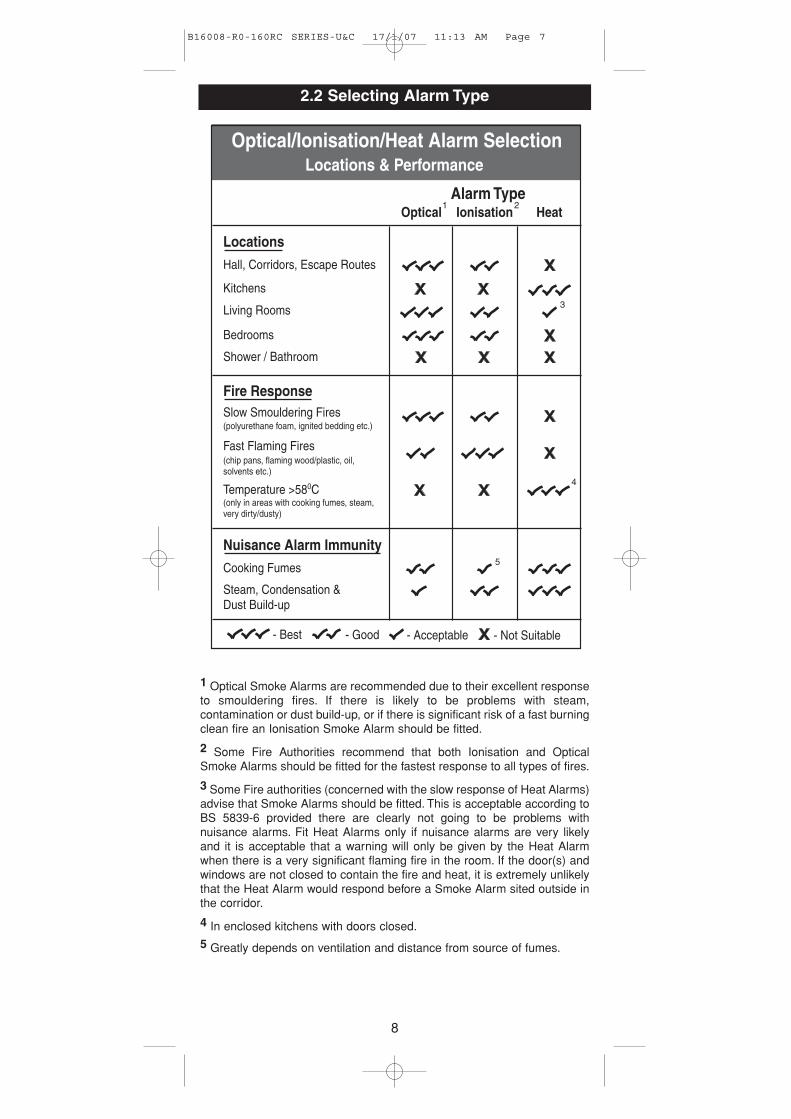
2.2 Selecting Alarm Type
1 Optical Smoke Alarms are recommended due to their excellent responseto smouldering fires. If there is likely to be problems with steam,contamination or dust build-up, or if there is significant risk of a fast burningclean fire an Ionisation Smoke Alarm should be fitted.
2 Some Fire Authorities recommend that both Ionisation and OpticalSmoke Alarms should be fitted for the fastest response to all types of fires.
3 Some Fire authorities (concerned with the slow response of Heat Alarms)advise that Smoke Alarms should be fitted. This is acceptable according toBS 5839-6 provided there are clearly not going to be problems withnuisance alarms. Fit Heat Alarms only if nuisance alarms are very likelyand it is acceptable that a warning will only be given by the Heat Alarmwhen there is a very significant flaming fire in the room. If the door(s) andwindows are not closed to contain the fire and heat, it is extremely unlikelythat the Heat Alarm would respond before a Smoke Alarm sited outside inthe corridor.
4 In enclosed kitchens with doors closed.
5 Greatly depends on ventilation and distance from source of fumes.
8
Locations
Hall, Corridors, Escape Routes
Alarm TypeOptical Ionisation Heat
Bedrooms
Shower / Bathroom
Kitchens
Living Rooms
Fire ResponseSlow Smouldering Fires(polyurethane foam, ignited bedding etc.)
Nuisance Alarm Immunity
Cooking Fumes
Steam, Condensation &Dust Build-up
Fast Flaming Fires(chip pans, flaming wood/plastic, oil,solvents etc.)
- Best - Good - Acceptable - Not Suitable
Temperature >580C(only in areas with cooking fumes, steam,very dirty/dusty)
Optical/Ionisation/Heat Alarm SelectionLocations & Performance
1 2
3
4
5
B16008-R0-160RC SERIES-U&C 17/1/07 11:13 AM Page 7
Improved Audibility
The effectiveness of Category LD2 and LD3 systems can besignificantly enhanced if an additional Smoke Alarm (interconnected)is installed in the master bedroom. This will help ensure that aresponsible person will quickly be alerted to a fire and can arrange foran orderly evacuation of children and other vulnerable occupants.
2.3 Grade D, E & F Systems
The mains powered Smoke and Heat Alarms with battery back-upcovered by these instructions are suitable for Grade D, E & F Systems.
A Grade D system is needed for:
- new or materially altered dwellings, up to three-storeys, with no floorover 200m2
- existing dwellings with poor structural fire precautions, up to threestoreys, with no floor over 200m2
- Houses in Multiple Occupation (HMOs) of one or two-storeys, withno floor over 200m2
- Individual dwellings units of two or more rooms in HMOs
Check that a Grade D system is adequate for the dwelling into whichthe system is being installed.
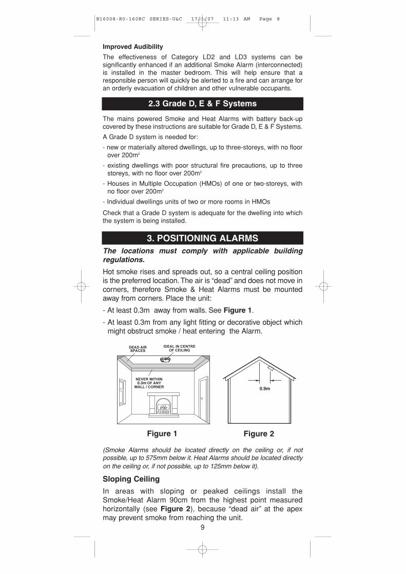
3. POSITIONING ALARMSThe locations must comply with applicable buildingregulations.
Hot smoke rises and spreads out, so a central ceiling positionis the preferred location. The air is “dead” and does not move incorners, therefore Smoke & Heat Alarms must be mountedaway from corners. Place the unit:
- At least 0.3m away from walls. See Figure 1.
- At least 0.3m from any light fitting or decorative object whichmight obstruct smoke / heat entering the Alarm.
(Smoke Alarms should be located directly on the ceiling or, if notpossible, up to 575mm below it. Heat Alarms should be located directlyon the ceiling or, if not possible, up to 125mm below it).
Sloping Ceiling
In areas with sloping or peaked ceilings install theSmoke/Heat Alarm 90cm from the highest point measuredhorizontally (see Figure 2), because “dead air” at the apexmay prevent smoke from reaching the unit.
0.9m0.3m
Figure 1 Figure 2
9
B16008-R0-160RC SERIES-U&C 17/1/07 11:13 AM Page 8
3.1 Locations To Avoid
DON’T place Smoke Alarms in any of the following areas:• Bathrooms, kitchens, shower rooms, garages or other rooms where the
smoke alarm may be triggered by steam, condensation, normal smoke orfumes.Keep at least 6 metres away from sources of normal smoke/fumes.
DON’T place Heat Alarms in any of the following areas:• Bathrooms, shower rooms or other rooms where the unit may be
triggered by steam or condensation.
DON’T place Smoke or Heat Alarms in any of thefollowing areas:
• Places where the normal temperature can exceed 40°C or be below4°C (e.g. attics, furnace rooms, directly above ovens or kettles etc.)as the heat/steam could cause nuisance alarms.
• Near a decorative object, door, light fitting, window moulding etc.,that may prevent smoke or heat from entering the Alarm.
• Surfaces that are normally warmer or colder than the rest of the room(e.g. attic hatches). Temperature differences might stop smoke or heatfrom reaching the unit.
• Next to or directly above heaters or air conditioning vents, windows,wall vents etc. that can change the direction of airflow.
• In very high or awkward areas (e.g. over stairwells) where it may bedifficult to reach the alarm (for testing, hushing or batteryreplacement).
• Locate away from very dusty or dirty areas as dust build-up in thechamber can impair performance. It can also block the insect screenmesh and prevent smoke from entering the smoke detectorchamber.
• Locate the unit at least 1m from dimmer controlled lights and wiringas some dimmers can cause interference.
• Locate unit at least 1.5m and route wiring at least 1m away fromfluorescent light fittings as electrical “noise” and/or flickering mayaffect the unit. Do not wire into the same circuit as fluorescent lightsor dimmers.
• Do not locate in insect infested areas. Small insects getting into thesmoke detector chamber can cause intermittent alarms. Insects andcontamination on the Heat Alarm sensor can increase its responsetime.
4. INSTALLATION
The Alarm is designed to be permanently mounted , using it’sown built-in terminal block to connect it to the mains. Themounting plate can be screwed directly to the ceiling.Alternatively it can be screwed to a standard junction box. Itrequires a current of 40mA. The Alarm must not be exposedto dripping or splashing. There are important markings on theunderside of the alarm.
IMPORTANT PRECAUTION: Do not install the Alarms innew or renovated buildings until all work is completed(including floor coverings) and the building has beenfully cleaned. The wiring can be installed when
10
B16008-R0-160RC SERIES-U&C 17/1/07 11:13 AM Page 9
appropriate. (Excessive dust and debris from buildingwork can contaminate the smoke chamber or heat sensorand cause problems, it will also invalidate the guarantee).If it must be installed, first cover it completely, particularlyaround the edges, with a dust cover (eg. with theelasticated cover supplied or a plastic bag), until allcleaning is finished.
The Alarm must not be connected when the house wiringinsulation is being checked with high voltages.i.e. Do not use a high voltage insulation tester on the alarm.
WARNING: Mains operated Alarms should be installed andinterconnected by a qualified electrician in accordance withthe Regulations for Electrical Installations published by theInstitution of Electrical Engineers (BS7671). Failure to installthis Alarm correctly may expose the user to shock or fire hazards.
WARNING: The Alarm must be continuously powered 24hours a day so it is important that it is not on a circuit that canbe turned off by a switch.
Note: BS 5839-6 2004 gives the folowing recommendations regarding themains supply to be used in a Grade D system (The Ei141/146/161RC/166RC Smoke Alarms and Ei144/164RC Heat Alarms can be usedin a Grade D system). The power supply for the Alarms should be derivedfrom the public electricity supply to the dwelling. The mains supply to theAlarms should take the form of either:
(a) an independent circuit at the dwelling’s main distribution board, in whichcase no other electrical equipment should be connected to this circuit(other than a dedicated monitoring device installed to indicate failure of themains supply to the Alarms); or
(b) a separately electrically protected, regularly used local lighting circuit.
Alarms should be connected on a single final circuit, unless the means ofinterconnection is by radio signals (e.g. RadioLINK).
(See BS 5839-6: 2004 for further information)
Note: The Ei Electronics RadioLINK Base Ei168RC (for use withEi161RC/164RC/166RC models only) can be used to eliminateinterconnect wiring, make system extensions and provide simple and costeffective compliance with BS 5839-6: 2004.
4.1 Mounting & Wiring Alarms
1. Select a location complying with the advice in previoussections (see pages 4-10).
2. Disconnect the AC mains supply from the circuit that isgoing to be used.
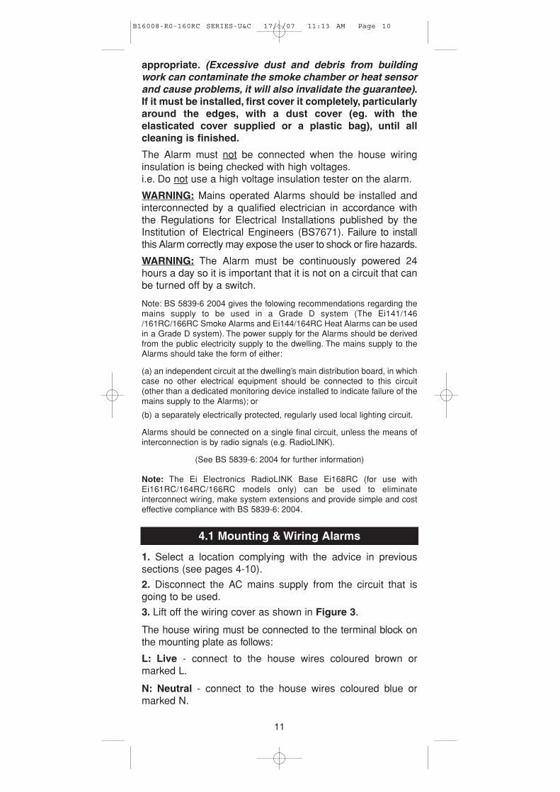
3. Lift off the wiring cover as shown in Figure 3.
The house wiring must be connected to the terminal block onthe mounting plate as follows:
L: Live - connect to the house wires coloured brown ormarked L.
N: Neutral - connect to the house wires coloured blue ormarked N.
11
B16008-R0-160RC SERIES-U&C 17/1/07 11:13 AM Page 10
See page 14 for information on interconnection.
Note: Wiring must be installed in compliance with localregulations.
Warning: Mixing the Live and Neutral connections wheninterconnecting alarms will damage all the alarms - ensurethat the same colours are used throughout the premisesfor Live, Neutral and Interconnect wires.
We strongly recommend that you check for the followingbefore connecting the alarm:
• check for Live and Neutral using a two probe tester.• check for Live using a neon tester.• check that the Interconnect wire is NOT connected to Live,
Neutral or Earth. Do not use an Earth wire for theInterconnect line.
N.B.The alarm does not need to be earthed. However the terminalmarked is provided for the convenience of the installer so thatany copper Earth wire or cable coloured green & yellow, can besafely terminated.
To interconnect the Alarms connect all the IC terminals togetheras shown in Figure 4 (see “Interconnecting Alarms” sectionon page 14).
4. If the mains wires are recessed, bring the wires through therear hole in the mounting plate as shown in Figure 4.
REMOVEABLETRUNKING DOOR FOR
Figure 4
12
FOAM CEILING GASKET
INSERT SCREWDRIVERTO LIFT AND REMOVE
WIRING COVER
Figure 3
B16008-R0-160RC SERIES-U&C 17/1/07 11:13 AM Page 11
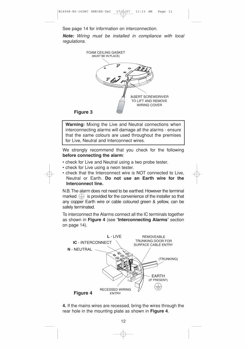
If the mains wires are being brought along the surface:
(a) position the mounting plate so the cable trunking is asshown in Figure 4.
(b) the mounting plate has a removable section, take it out tointerface directly with 25 mm conduit as shown in Figure 5. Ifinterfacing to 16 mm conduit carefully cut around the markedsection, leaving the top intact and replace the section. (If youare not using surface wiring, the removable section must beleft in place for electrical safety reasons).
There are two other positions which are also suitable for thesurface wiring to enter (and exit) the alarm, one next to theremovable section and another directly opposite.
5. Carefully align the mounting plate and screw into place.Connect the wires to the terminal block. With recessed wiring,ensure the rear gasket seals around the edge of the hole inthe ceiling or wall. This is to prevent air draughts affecting thesmoke/heat entering the alarm. If the hole is too large or thealarm does not seal it, it should be sealed with silicone rubberor equivalent.
6. Replace the wiring cover. Check the alarm battery isconnected (Ei141/144/146 only).
7. Carefully line up the unit on the base and slide on.8. Press and hold the test/hush button for 10 seconds. Thehorn will sound. Check that any interconnected alarms alsosound within this period.
9. Connect the mains power to the alarm circuit. Check thegreen light is on.
10. Attach the ‘Smoke Alarm’ identification label provided tothe distribution board to identify the alarm circuit.
11. Attach the ‘Mains Smoke / Heat Alarms’ label provided onor near the distribution board and write in date installed andthe number of alarms on the circuit.
Ensure the alarm operates correctly - see “TESTING &MAINTAINING YOUR ALARM” section on page 4 of theUSER INSTRUCTIONS.
13
Figure 5
B16008-R0-160RC SERIES-U&C 17/1/07 11:13 AM Page 12
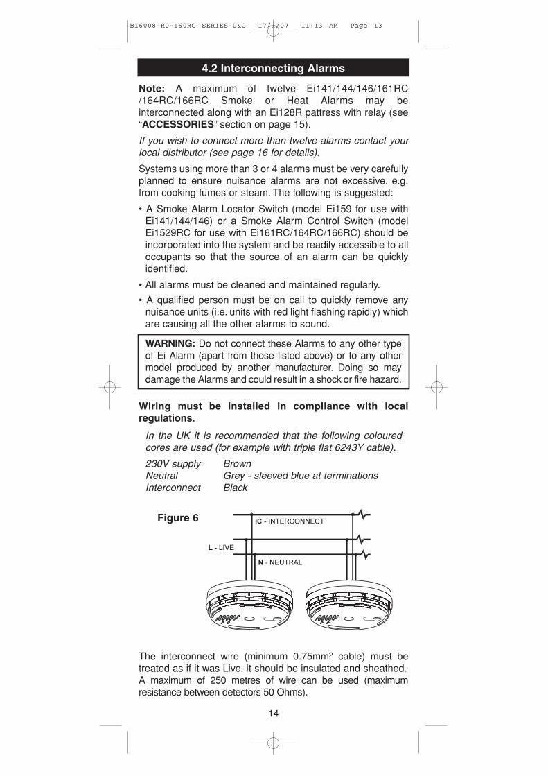
4.2 Interconnecting Alarms
Note: A maximum of twelve Ei141/144/146/161RC/164RC/166RC Smoke or Heat Alarms may beinterconnected along with an Ei128R pattress with relay (see“ACCESSORIES” section on page 15).
If you wish to connect more than twelve alarms contact yourlocal distributor (see page 16 for details).
Systems using more than 3 or 4 alarms must be very carefullyplanned to ensure nuisance alarms are not excessive. e.g.from cooking fumes or steam. The following is suggested:
• A Smoke Alarm Locator Switch (model Ei159 for use withEi141/144/146) or a Smoke Alarm Control Switch (modelEi1529RC for use with Ei161RC/164RC/166RC) should beincorporated into the system and be readily accessible to alloccupants so that the source of an alarm can be quicklyidentified.
• All alarms must be cleaned and maintained regularly.
• A qualified person must be on call to quickly remove anynuisance units (i.e. units with red light flashing rapidly) whichare causing all the other alarms to sound.
WARNING: Do not connect these Alarms to any other typeof Ei Alarm (apart from those listed above) or to any othermodel produced by another manufacturer. Doing so maydamage the Alarms and could result in a shock or fire hazard.
Wiring must be installed in compliance with localregulations.
In the UK it is recommended that the following colouredcores are used (for example with triple flat 6243Y cable).
230V supply BrownNeutral Grey - sleeved blue at terminationsInterconnect Black
The interconnect wire (minimum 0.75mm2 cable) must betreated as if it was Live. It should be insulated and sheathed.A maximum of 250 metres of wire can be used (maximumresistance between detectors 50 Ohms).
14
Figure 6
B16008-R0-160RC SERIES-U&C 17/1/07 11:13 AM Page 13
These Smoke/Heat Alarms should be interconnected only withinthe confines of a single family living unit. If they are connectedbetween different units there may be excessive nuisancealarms. Everybody may not be aware that they are being testedor that it is a nuisance alarm caused by cooking etc.
Ensure the alarms operate correctly - see “TESTING &MAINTAINING YOUR ALARM” section on page 4 of theUSER INSTRUCTIONS.
5. ACCESSORIES
Relay Module Ei128R:
The Ei128R module has a relay rated at 250V AC / 5 Amps.This is useful for remote signalling and turning on lights etc.Also available is the Ei128RBU Relay Module which hasbattery back-up.
Alarm Locator Ei159:(for use with models Ei141/144/146 only)
The Smoke Alarm locator is recommended for systems withthree or more Smoke / Heat Alarms as it helps quickly identifythe unit in alarm and reduces the impact of nuisance alarms.
Pressing the Smoke Alarm Locator button will silence allinterconnected alarms for 10 minutes, except those sensingfire. It is easily installed between the Interconnect and Neutralterminals.
Alarm System Control Switch Ei1529RC:(for use with models Ei161RC/164RC/166RC only)
The System Control Switch is recommended for systems withthree or more Smoke / Heat Alarms. It allows the user toperform the following functions from a remote location:
LOCATE - If alarms sound press Locate to allow source of alarm to be identified.
HUSH - Press Hush to silence nuisance alarms.TEST - Operate weekly to Test the alarms.MAINS CHECK - Test will not work with mains absent.
RadioLINK Base Ei168RC:(For use with models Ei161RC/164RC/166RC only)
The RadioLINK Bases are used to eliminate interconnectwiring, make system extensions and provide simple and costeffective compliance with BS 5839-6: 2004.
An Ei168RC with Ei161RC, 164RC and 166RC Smoke/HeatAlarms allows the units to be remotely tested, silenced andthe fire located using the optional Ei411H RadioLINK controlswitch.
15
B16008-R0-160RC SERIES-U&C 17/1/07 11:13 AM Page 14
Aico Ltd. Mile End Business Park, Maesbury Rd, Oswestry,
Shropshire SY10 8NN, U.K. Tel: 0870 758 4000
www.aico.co.uk
Ei Electronics. Shannon, Co Clare, Ireland. Tel: 061 471277
www.eielectronics.com
1
2
3
4
4
8
9
9
10
10
11
14
15
1. QUICK GUIDE
1.1 INSTALLATION GUIDE
1.2 ALARM REMOVAL
2. HOW MANY ALARMS TO INSTALL
2.1 CATEGORIES OF SYSTEM
2.2 SELECTING ALARM TYPE
2.3 GRADE D, E & F SYSTEMS
3. POSITIONING ALARMS
3.1 LOCATIONS TO AVOID
4. INSTALLATION
4.1 MOUNTING & WIRING ALARMS
4.2 INTERCONNECTING ALARMS
5. ACCESSORIES
INDEX
16
B16008-R0-160RC SERIES-U&C 17/1/07 11:13 AM Page 15
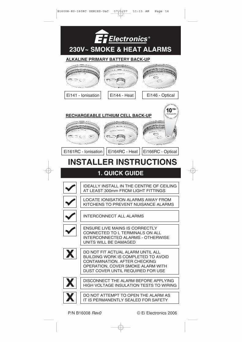
INSTALLER INSTRUCTIONS
IDEALLY INSTALL IN THE CENTRE OF CEILINGAT LEAST 300mm FROM LIGHT FITTINGS
LOCATE IONISATION ALARMS AWAY FROMKITCHENS TO PREVENT NUISANCE ALARMS
ENSURE LIVE MAINS IS CORRECTLYCONNECTED TO L TERMINALS ON ALLINTERCONNECTED ALARMS - OTHERWISEUNITS WILL BE DAMAGED
DO NOT FIT ACTUAL ALARM UNTIL ALLBUILDING WORK IS COMPLETED TO AVOIDCONTAMINATION. AFTER CHECKINGOPERATION, COVER SMOKE ALARM WITHDUST COVER UNTIL REQUIRED FOR USE
DISCONNECT THE ALARM BEFORE APPLYINGHIGH VOLTAGE INSULATION TESTS TO WIRING
DO NOT ATTEMPT TO OPEN THE ALARM ASIT IS PERMANENTLY SEALED FOR SAFETY
INTERCONNECT ALL ALARMS
Ei141 - Ionisation Ei144 - Heat Ei146 - Optical
RECHARGEABLE LITHIUM CELL BACK-UP
Ei161RC - Ionisation Ei166RC - OpticalEi164RC - Heat
230V~ SMOKE & HEAT ALARMSALKALINE PRIMARY BATTERY BACK-UP
© Ei Electronics 2006P/N B16008 Rev0
B16008-R0-160RC SERIES-U&C 17/1/07 11:13 AM Page 16