Embed Size (px)
Citation preview
Ringaskiddy Waste Management Facility Environmental Impact Statement
11 Geology, Soils, Surface Water and Groundwater
11 .I Introduction
This chapter describes the geology, soils, surface water and groundwater at the site of the
proposed development. This information is based on a detailed soil and hydrogeological
investigation carried out by KT Cullen & Co. Ltd., as part of the environmental ‘due diligence’
investigation of the site prior to.purchase, and a desk study and some additional trial pitting by
Arup Consulting Engineers.
The impact of the construction and operation of the development on the underlying soils, geology
and hydrology is discussed and evaluated. The mitigation measures proposed and the residual
effects conclude this chapter.
11.2 Existing Geology, Soils, Surface Water and Groundwater
11.2.1 Geology
Regional Geology
During the Carboniferous period (circa 300 million years ago), limestone was deposited in what
was then the shallow tropical seas of the North Munster shelf. This limestone was laid down on
Devonian Old Red Sandstone. At the end of the Carboniferous Period, the rocks of the South
Cork region were uplifted, folded and faulted by the Variscan Orogeny (mountain-building period).
This gave rise to a series of steep-flanked and sometimes overturned anticlines and synclines
formed from Water-ford to Kerry. The anticlinal ridges have brought the Old Red Sandstone to the
surface, with the Carboniferous Limestone having been eroded from the ridge crests.
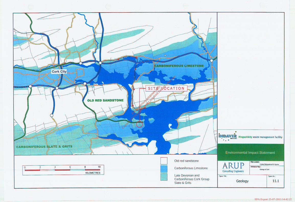
As a result, the topography of South Cork and the Cork Harbour region is characterised by
elongate east-north-east to west-south-west valleys separated by intervening ridges. Devonian
Old Red Sandstones generally form the high ground while Carboniferous Limestones are
generally exposed in the valleys. The geology of the site and the surrounding area is shown in
Figure 11.1.
Local Geology
The bedrock consists of pale green/grey mudstone, and is typical of the Lower Carboniferous
Kinsale Formation (Cuskinny Member). It is thought to be approximately 240 metres thick. This
member is typically made up of flaser-bedded (rippled) sandstones and lenticular-bedded
mudstone. It has been described as being composed of relatively thick sometimes conglomeratic
sandstone units, alternating with thin sandstone laminated mudstone, massive claystone and
heterolithic sediments (which comprises the range from sand-lensed mudstones to flaser-bedded
sandstones).
Arup Consulting Engineers lndaver EIS-‘2746.10
Issue No.1 November 2001 Page 1 of 6
For
insp
ectio
n pur
pose
s only
.
Conse
nt of
copy
right
owne
r req
uired
for a
ny ot
her u
se.
EPA Export 25-07-2013:14:42:22
Ringaskiddy Waste Management Facility Environmental Impact Statement
11.2.2 Soils
Regional Soils
The Quaternary Period which extended from the beginning of the last Ice Age (1.6 million years
ago) to the present is the last period of the geological timescale. Sediment composition for this
period varies depending on the type of substrate that the ice flowed over.
Most of the surface deposits in the South Cork area were deposited during the Quaternary
Period, largely during the Ice Age itself. They were deposited directly from the glacier ice or the
meitwater flowing from it. In the former case it became till or boulder clay (mixture of sediments
ranging in size from clay to boulders), and in the later case it was sorted and deposited
separately as gravel, sand, silt or clay.
Local Soils
The overburden geology consists of a shallow topsoil layer underlain by soft silty clays with some
fine sands and gravels. Depth to bedrock varies across the site, from 1.0 metres below ground
level (bgl) to greater than 9.0 metres bgl. This thickness variation is a reflection of the undulating
pre-glacial topography and the removal of the material from the site in the past.
Sands were encountered in some areas and these areas are likely to allow water to be stored and
to move through the subsurface. As some of the overburden is less than 1 .O metre in thickness,
vertical migration of water directly into the bedrock aquifer is likely.
11.2.3 Hydrology
Regional Drainage
The eastern boundary of the site lies within 50m of the West Channel in Cork Lower Harbour.
Local Drainage
Surface water within the site boundary appears to drain through naturally occurring channels
along the field boundaries, following the natural topography of the landscape, generally towards
the north of the site. Drainage is poor close to the road where the ground is very flat, resulting in
some ponding of surface water on this portion of the site.
11.2.4 Hydrogeology
The groundwater potential of Irish rocks is typically a function of fissure flow movements and
storage, which is controlled by the intensity and development status of fissures, fractures and
joints. The bedrock underlying the site is thought to be generally unproductive (i.e. individual well
yields of less than 100 m3/day and often lower than 40 m3/day - Geological Survey of Ireland
‘Geology of South Cork”, 1995) although hydrogeological data is limited.
Arup Consulting Engineers lndaver EIS-C796.10
Issue No.1 November 2001 Page 2 of 6
For
insp
ectio
n pur
pose
s only
.
Conse
nt of
copy
right
owne
r req
uired
for a
ny ot
her u
se.
EPA Export 25-07-2013:14:42:22
For
insp
ectio
n pur
pose
s only
.
Conse
nt of
copy
right
owne
r req
uired
for a
ny ot
her u
se.
EPA Export 25-07-2013:14:42:22
Ringaskiddy Waste Management Facility Environmental Impact Statement
Water strikes were observed between 5 and 12 metres below ground level in the overburden, typically occurring beneath the clays and immediately above the clean bedrock in the fractured/weathered zone.
Soil and groundwater sampling and analysis carried out during the ‘due diligence’ site investigation suggests that there is no soil or groundwater contamination.
II .3 Sub-Surface Characteristics of the Proposed Development
There will be some works carried out below the existing ground levels. These works may include the following:
diversion of services as necessary and installation of new services strip topsoil earthworks and site regrading construct earth retaining structures excavation to form a slab level at -5.Om below ground level construct foundations construction of bunker and underground water tanks construction of underground firewater retention tank.
Site preparation will involve the regrading of the lower part of the site for the construction of the waste-to-energy building. The road profile will require some cut and fill to be carried out. The middle of the site will require significant earth retaining structures. Excavation will be minimised at the high level along the southern edge of the site, but some earth retaining structures will be required at the site boundary. The site for the waste transfer station/community recycling park will also require some regrading.
1 I .4 Onsite Drainage
A description of the proposed onsite drainage is given below.
11.4.1 Standards and Regulations
All of the underground drainage systems will be designed and constructed as a minimum to comply with the Building Regulations 1997, BS EN 752-4 and BS 6367 Drainage for Roofs and Paved Areas.
11.4.2 Surface Water Drainage
The surface water from the proposed facility will be collected in a number of separate drainage systems. The design of the surface water drainage network for the development is based on a rainfall return period of 1 year with a maximum rainfall intensity of 50mmlhr. The storm water retention tanks are designed for a 20mmlhr rainstorm lasting 2hrs. These figures have been calculated based on previous experience in designing water retaining tanks in the Ringaskiddy area. There will be additional capacity for the storage of firewater run-off.
Arup Consulting Engineers Indaver EIS-C796.10
Issue No.1 November 2001 Page 3 of 6
For
insp
ectio
n pur
pose
s only
.
Conse
nt of
copy
right
owne
r req
uired
for a
ny ot
her u
se.
EPA Export 25-07-2013:14:42:22
Ringaskiddy Waste Management Facility Environmental Impact Statement
11.4.3 Roof Drainage
All of the surface water run-off from the roofs of the waste to energy facility will be collected and
stored in a rainwater storage tank. The collected rainwater will then be used in the process. There
will be an overflow from the rainwater tank to the storm water retention tank. Refer to section
11.4.4.
Rainwater from the roofs in the waste transfer station and the roof of the building in the
community recycling park will discharge directly to the Cork County Council surface water sewer.
11.4.4 Drainage of Hard Standings
The surface water runoff from the hard standing areas in the waste to energy plant will be
collected in a dedicated system and discharged to a storm water retention tank. The contents of
the retention tank will be monitored, to ensure that it is not contaminated, prior to discharge to the
surface water sewer. If contaminated, the contents of the tank will be tranferred to the furnace or
taken offsite for disposal.
Surface water run off from the waste transfer station hard standings and marshalling areas will be drained to a surface water retention tank, and tested for contamination, p;ior to release to the
surface water sewer. The contents of the tank will be transferred to the furnace or sent offsite for
disposal if contamination is found.
Run off from car parking areas in the waste management facility and from the community
recycling park will be collected in a separate system and discharged via a hydrocarbon
interceptor to the surface water sewer.
11.4.5 Bunded Areas Drainage
The surface water run-off from tank bunds and bunded areas, the tanker sampling areas, the
tanker unloading areas and the direct injection hard-standing area in the waste to energy plant
will be collected in a dedicated sump and tested. Uncontaminated water run-off will be discharged
to the storm water retention tank. Contaminated run-off will be sent to the furnace for disposal.
The drum wash area and the tankfarm bunds in the waste transfer station will drain to a sump,
from which it will be collected and disposed of to the furnance, or sent offsite for disposal.
II .4.6 Sanitary Drainage
The waste to energy facility and the waste transfer station will have separate packaged sewage
treatment plants. The treated effluent will discharge into the existing Cork County Council foul
water sewer, which runs along the road.
11.5
11.5.1
Evaluation of Potential Impacts
Soils and Geology impacts
Consfrucfion Phase
Some work below the existing ground level will be required as outlined in section 11.3 above. It is
intended, where possible, to reuse the excavated material onsite. All material excavated that
Arup Consulting Engineers lndaver EIS-C796.10
Issue No.1 November 2001 Page 4 of 6
For
insp
ectio
n pur
pose
s only
.
Conse
nt of
copy
right
owne
r req
uired
for a
ny ot
her u
se.
EPA Export 25-07-2013:14:42:22
Ringaskiddy Waste Management Facility Environmental impact Statement
cannot be reused onsite, will be sent offsite for reuse or disposal at a licensed waste disposal
site.
Operational Phase
When operational, it is anticipated that the development will not cause any impact on the soils
and geology of the site. All substances that would have the potential to cause a negative impact
on the soils and geology will be stored and handled in bunded areas or within water proof tanks.
11.5.2 Potential Surface and Groundwater Impacts
Consfrucfion Phase
Potential sources of pollution, include fuels, lubricants and paints.
Operational Phase
There will be no direct discharges to groundwater during the operational phase of the
development
Potential sources of pollution during the operational phase of the facility, could be the accidental
spillage or leakage of wastes, particularly waste solvents. Other potential sources of pollution that
may have an effect on surface or groundwater during the operational phase could be oil/fuel leaks
from parked cars, trucks and service vehicles.
However, it is anticipated that, with the following mitigation measures and good operational
management, the risk of any pollution occurring to the soil, groundwater and surface water will be
greatly minimised.
11.6 Mitigation Measures
Construction Phase
The employment of good construction management practices will serve to minimise the risk of
pollution. The Construction Industry Research and Information Association (CIRIA) in the UK has
issued a guidance note on the control and management of water pollution from construction sites,
Control of Water Pollution from Construction Sites, Guidance for Consultants and Contractors, C//?/A, 2007. The construction management of the site will take account of the findings of this
document to minimise as far as possible the risk of spillage that could lead to soil and
groundwater or surface water contamination.
Any chemicals, oils, paints or other potentially polluting substances used during construction will
be stored in properly bunded areas which will contain any spillage that may occur.
All appropriate methods, such as the use of silt pits, will be utilised to ensure that surface water
arising during the course of the construction activities will contain minimum sediment, prior to
discharge to the surface water drainage system.
Best practice in design and construction will be employed for the installation of storm water and
sanitary drainage.
Arup Consulting Engineers lndaver EIS-C796.10
Issue No.1 November 2001 Page 5 of 6
For
insp
ectio
n pur
pose
s only
.
Conse
nt of
copy
right
owne
r req
uired
for a
ny ot
her u
se.
EPA Export 25-07-2013:14:42:22
Ringaskiddy Waste Management Facility Environmental Impact statement
11.7
11.8
Operational Phase
All storage tanks for chemicals in the waste to energy facility will be fully bunded, as will drum
storage areas and storage tanks in the waste transfer station. Run-off from fire fighting, which
could be contaminated, will drain to the surface water drainage system and will be collected in the
storm water retention tanks. All underground process drains or process pipelines will be double
contained.
Rainwater run-off from hard standing and yard areas will be collected in a tank where it will be
sampled, as described in section 11.4 above, to ensure that contaminated surface water will not
be discharged from the site.
Solid wastes delivered to the facility will be stored in a waste bunker while awaiting thermal
treatment. The waste bunker will drain to a sump, which will be designed in accordance with the
relevant standards for water retaining structures. These mitigation measures will prevent any
potential leakage of leachate from the waste to soil or groundwater.
The community recycling park area will provide for the collection of a number of types of waste
including waste oil and car batteries which will be then be transported off-site for treatment. The
waste oil and batteries will be stored in special containers to contain fully atiy spillage that might
occur.
Hydrocarbon interceptors will be placed on surface water lines draining car-parking areas in the
waste to energy plant, the waste transfer station and the hardstanding areas/cat-parking areas at
the community recycling park. This is in order to contain any leakage of fuel or oil from vehicles
on site, and prevent any contamination of surface water.
A network of groundwater monitoring wells will be installed on the site. Regular monitoring of
groundwater will take place, which will detect any changes in groundwater quality during the
operational phase of the development.
Residual Impacts
It is anticipated that with the implementation of the mitigation measures above, neither the
construction, nor operational phases of the project will result in any significant negative impacts
on the geology, soils, surface water and hydrogeology of the site.
References
Nevill W. E. (1963) Geoloqv and Ireland. Dublin: Allen Figgis
Geological Survey of Ireland (1994) Geoloqv of South Cork-Geological Survey of Ireland. Dublin
Masters-Williams H et al (2001) Control of Water Pollution from Construction Sites: Guidance for
Consultants and Contractors, Construction Industry Research and Information Association
(CIRIA), London
Arup Consulting Engineers Indaver EIS-C796.10
Issue No.1 November 2001 Page 6 of 6
For
insp
ectio
n pur
pose
s only
.
Conse
nt of
copy
right
owne
r req
uired
for a
ny ot
her u
se.
EPA Export 25-07-2013:14:42:22