Embed Size (px)
Citation preview

11 - Advanced Systems

B A A - 1 2 9 - 1
N M I LIBRARY - DO N O T R E M O V E
©US Department of TransportationFederal Railroad Administration
State-of-the-Art A s se s sm e n t of Guidew ay Sy ste m s for M ag le v App lications
National Maglev Initiative Washington, DC 20590
D O T/FR A /N M I-92 /17 O ctober 1992 This docum ent is available to the Final Report U.S. public through the National
Technical Information Service, Springfield, Virginia 22161

Technical Report Documentation Pag*I. Rhwi n«.
DOT/FRA/NMI-92/17
2. Accession Ns.PB93-154862
3. Dsiisisih's Cstslsi Ns.
Title end SubtitleSta te -o f-th e -A rt Assessment of Guidevay Systems fo r Maglev A pp lication s
5. Seeert OeteOctober 1992
6. P«f tn)inf Orf«Ainfion Cod*OSP-91-251
7. Author's/ GangaRao, Barbero, Chen, Davalos, Eck, Halabe, Klinkhachorn. Raju, and Spyrakos________
S. Performing Organization fieeort No.
CFC-92-144___9. Portorminf Orf«MSdtion Nomo on« Ad rosa
Constructed F a c i l i t ie s Center Room 653E Engineering Sciences Bu ild ing West V irg in ia U n ive rs ity Morgantown, WV 26506-6101_____________
10. Worb Unit No. iTRAIS)
II. Contract or Srent No.DTFR53- 91-C -00084
12. Saansarmg Agency Name and AddressUSDOT - Federal Ra ilroad Adm inistration O ffice o f Research and Development 400 Seventh Street,. S.W.Washington, D.C. 20590
13. Type et Reeert ene Perioo Co«erec
F in a l Repcrrt:
August 1991 - July 199214. Spensermg Agency Coca
IS. Supplementary Nates
Id. Abstreet
The engineering, environmental, diagnostic, and economic feasibility of Maglev guideway systems are assessed with an emphasis on composite materials as directed by Congress. This study further examines the performance and the cost of existing and innovative guideway systems that are applicable to Maglev and other mass transit guideways. Utilizing parameters such as strength, stiffness, and ease of construction and maintenance, sixteen conceptual systems are developed for preliminary studies and seven are finalized for an in-depth study. These seven systems are as follows: 1) trapezoidal concrete box with steel; 2) trapezoidal concrete box with fiber reinforced plastics (FRP); 3) rectangular concrete box; 4) all steel; 5) hybrid-system with concrete decking stiffened by steel truss; 6) hybrid-system with concrete decldng stiffened by FRP truss; 7) all FRP box system. After establishing ten different load conditions and several serviceability criteria, the above systems have been evaluated for their applicability as Maglev guideway superstructures spanning 24.4 to 30.48 m (80 to 100 feet). Technical issues such as electromagnetic drag forces, sectional efficiency, feasibility of manufacturing, mass production, maintainability of system, and others have been studied along with feasibility to monitor these systems for degradation rates. In addition, economic data of mass transit system have been evaluated and extended to Maglev guideway systems. The maintenance cost data have been developed only to a limited degree. Finally, a set of options including a test plan in terms of laboratory, field experiment, and field demonstration phases is provided.
17. k«T «•*<* Transit Guidevay, Maglev
T ransit Guidevay, Maglev Guidevay, Stee l, Concrete, Hybrid Composite M ate ria l, Design Loads, Construction, M odularization, Nondestructive
II. Dlasnkwnan ti r ssui'Document i s ava ilab le to the U.S. public through the Nationa l Technical Inform ation Service, Sp r in g fie ld , VA 22161
17. Saawnty Clsssil. 1,1 Ais isssnljn
X. isiwr, Classil. (tl Hmi psgsi 21* N*. P«f«s 22.
u n c la ss if ie d u n c la ss ifie d
Farm DOT F 1700.7 i»-72> UfowtuHw of cMpUu/ psgs outKariza

METRIC/ENGL1SH CONVERSION FACTORS
ENGLISH TO METRIC
LENGTH (APPROXIMATE)1 inch (in.) - 2.5 centimeters (cm) 1 foot (ft) - 30 centimeters (cm) 1 yard (yd) « 0.9mit»r(m)1 mile (mi) ■ 1.6 kilometer* (km)
AREA (APPROXIMATE)6.5 square centimeters (cm*)1 square inch (sq in. in*)
1 square foot (sq ft, ft*) ■ 0.09 square meter (m*) 1 square yard (sq yd. yd*) ■ 0.8 square meter (m*)1 square mile (sq mi. mi*) - 1 acre - 0.4 hectares (he) -
2.6 square kilometers (km*) 4,000 square meters (m*)
MASS - WEIGHT (approximate)1 ounce (oz) - 28 grams (gr)1 pound Ob) ■ .45 kilogram (kg)
1 short ton - 2.000 pounds Ob) ■ 0.9 tonne (O
VOLUME (APPROXIMATE)1 teaspoon (tsp)
1 tablespoon (tbsp) 1 fluid ounce (fl oz)
1 cup (c) 1 pint (pt)
1 quart (qt) 1 gallon (gal)
1 cubic foot (cu ft ft*) 1 cubic yard (cu yd. yd*)
■ 5 milliliters (ml)■ 15 milliliters (ml)■ 30 milliliters (ml)- 0.24 liter (I)- 0.47 liter (I)- 0.96 liter (I)- 3.8 liters 0)■ 003 cubic meter (m*)■ 0.76 cubic meter (m>)
TEMPERATURE (EXACT) t(*-32)(5/9)J*F - y*C
METRIC TO ENGLISH
LENGTH (APPROXIMATE)1 millimeter (mm) 1 centimeter (cm)
1 meter (m) 1 meter (m)
1 kilometer (km)
■ 0.04 inch (in)■ 0.4 inch (in)- 33 feet (ft)■ 1.1 yards (yd)- 0.6 mile (mi)
AREA (APPROXIMATE)1 square centimeter (cm*) - 0.16 square inch (sq in. in*)
1 square meter (m*) - 1.2 square yards (sq yd. yd*) 1 square kilometer (kn*) - 0.4 square mile (sq mi. mi*)1 hectare (he) - 10.000 square meters (m*) - 2.5 acres
MASS - WEIGHT (approximate)1 gram (gr) - 0.036 ounce (oz)
1 kilogram (kg) - 2.2 pounds (lb)1 tonne (t) * 1,000 kilograms (kg) - 1.1 short tons
VOLUME (APPROXIMATE)1 milliliter (ml)
1 liter (I) 1 liter (I) 1 liter (I)
1 cubic meter (m*) 1 cubic meter (m*)
0.03 fluid ounce (fl oz)2.1 pints (pt)1.06 quarts (qt)0.26 gallon (gal)36 cubic feet (cu ft, ft*)13 cubic yards (cu yd. yd*)
TEMPERATURE (EXACT) |(9/5)y ♦ 32J*C - a *F
QUICK INCH-CENTIMETER LENGTH CONVERSION
— f _ _ i ______i______i i i______i______i______ i______i_____ :■aNTMtnas a i > i « s • j a • so it u ti m is u n is is jo ji zi ij i« is
is so
QUICK FAHRENHEIT-CELSIUS TEMPERATURE CONVERSION
•» -0*1 |
*1
u*1
11*1
St*1
St*1
as*1
m*|
in*1
M0*|
ISO*1
lit*1
tt4*1
m*I
•c 1■«o*
1•so*
1•JO*
1.10*
1a*
1to*
1IS*
1SB*
140*
1so*
1SO*
170*
1to*
1to*
1too*
For more exact and or other conversion factors, see NBS Miscellaneous Publication 286, Units of Weights and Measures. Price 52.50. SO Catalog No. Cl 310286.

TABLE OF CONTENTS
List of Figures i
List of Tables iv
Forward vi
Executive Summary vii
1.0 Introduction 1
2.0 Objectives 4
3.0 Feasibility Assessment of Existing and Innovative 6Guideway Systems Adaptable to Maglev Applications
3.1 Review of Existing Guideway Systems and Their 6Potential Applicability to Maglev Guideways
3.2 Design Loads and Serviceability Limits 15
3.3 Identification and Development of Innovative Guideway Systems and 15Maglev Application
3.4 Performance Assessment for Maglev Guideway Systems 31
3.5 Potential Use of Innovative Materials 32
3.6 Comparative Assessment of Conventional and Innovative Materials 75
3.7 Feasibility of Utilizing Prototype Composite System 84
3.8 Selection of Most Promising Hybrid Systems 93
3.9 Analysis of Costs and Assessments of Economic Impact of Maglev 93Guideway
3.10 Development of Test Plan 126
4.0 Summary, Conclusions, and Options 152
4.1 Summary 154
4.2 Conclusions 160
4.3 Options for Future Work 161
5.0 References 166
Appendix 171
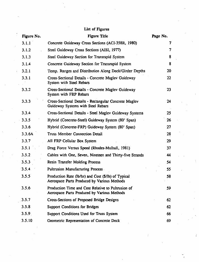
List of Figures
Figure No. Figure Title Page No.
3.1.1 Concrete Guideway Cross Sections (ACI-358R, 1980) 7
3.1.2 Steel Guideway Cross Sections (AISI, 1977) 7
3.1.3 Steel Guideway Section for Transrapid System 8
3.1.4 Concrete Guideway Section for Transrapid System 8
3.2.1 Temp. Ranges and Distribution Along Deck/Girder Depths 20
3.3.1 Cross-Sectional Details - Concrete Maglev Guideway 22System with Steel Rebars
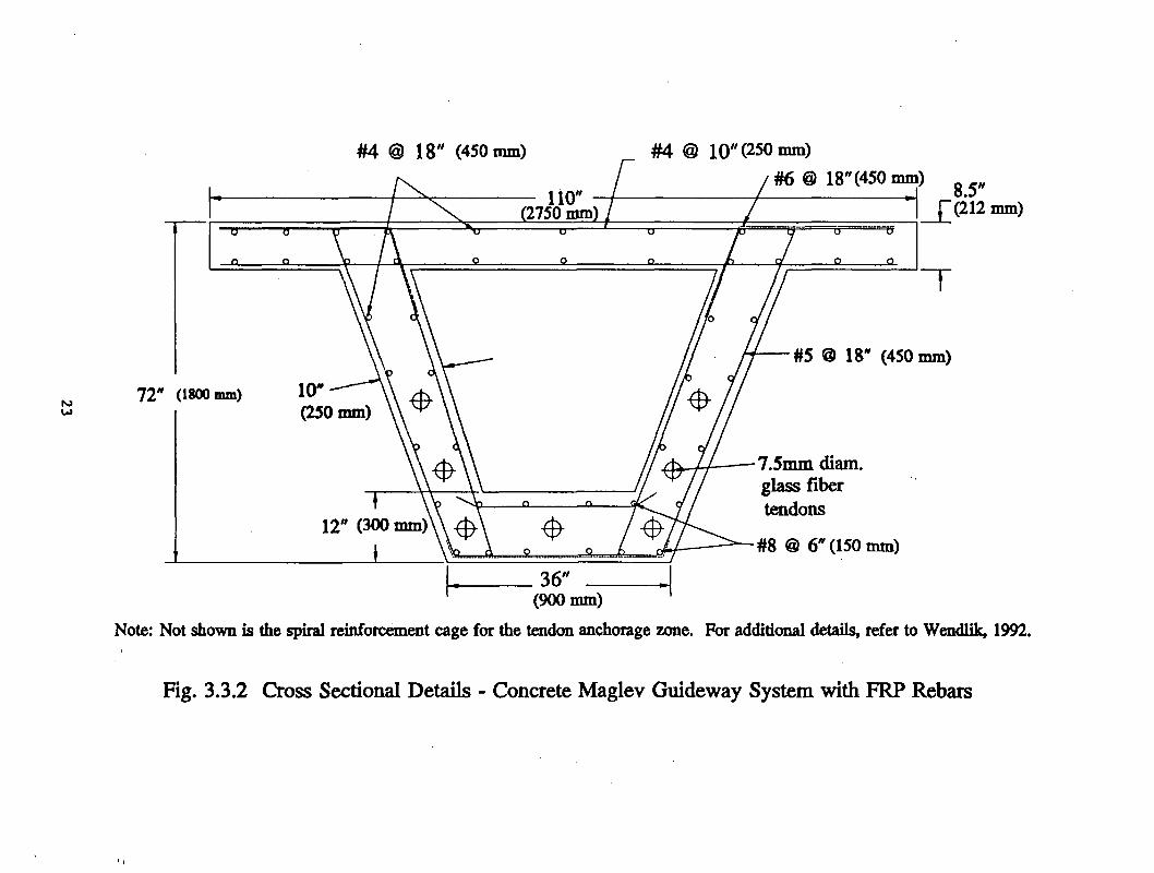
3.3.2 Cross-Sectional Details - Concrete Maglev Guideway 23System with FRP Rebars
3.3.3 Cross-Sectional Details - Rectangular Concrete Maglev 24Guideway Systems with Steel Rebars
3.3.4 Cross-Sectional Details - Steel Maglev Guideway Systems 25
3.3.5 Hybrid (Concrete-Steel) Guideway System (80’ Span) 26
3.3.6 Hybrid (Concrete-FRP) Guideway System (80’ Span) 27
3.3.6A Truss Member Connection Detail 28
3.3.7 All FRP Cellular Box System 29
3.5.1 Drag Force Versus Speed (Rhodes-Mulhall, 1981) 37
3.5.2 Cables with One, Seven, Nineteen and Thirty-five Strands 44
3.5.3 Resin Transfer Molding Process 54
3.5.4 Pultrusion Manufacturing Process 55
3.5.5 Production Rate (lb/hr) and Cost (S/lb) of Typical 58Aerospace Parts Produced by Various Methods
3.5.6 Production Time and Cost Relative to Pultrusion of 59Aerospace Parts Produced by Various Methods
3.5.7 Cross-Sections of Proposed Bridge Designs 62
3.5.8 Support Conditions for Bridges 62
3.5.9 Support Conditions Used for Truss System 66
3.5.10 Geometric Representation of Concrete Deck 69
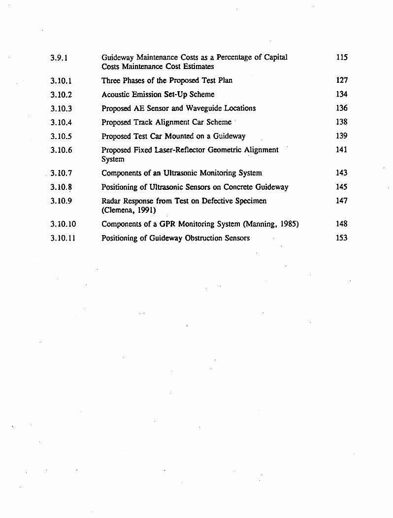
115
127134136138
139
141
143145147
148
153
Guideway Maintenance Costs as a Percentage of Capital Costs Maintenance Cost Estimates
Three Phases of the Proposed Test Plan
Acoustic Emission Set-Up Scheme
Proposed AE Sensor and Waveguide Locations
Proposed Track Alignment Car Scheme
Proposed Test Car Mounted on a Guideway
Proposed Fixed Laser-Reflector Geometric Alignment System
Components of an Ultrasonic Monitoring System
Positioning of Ultrasonic Sensors on Concrete Guideway
Radar Response from Test on Defective Specimen (Clemena, 1991)
Components of a GPR Monitoring System (Manning, 1985)
Positioning of Guideway Obstruction Sensors
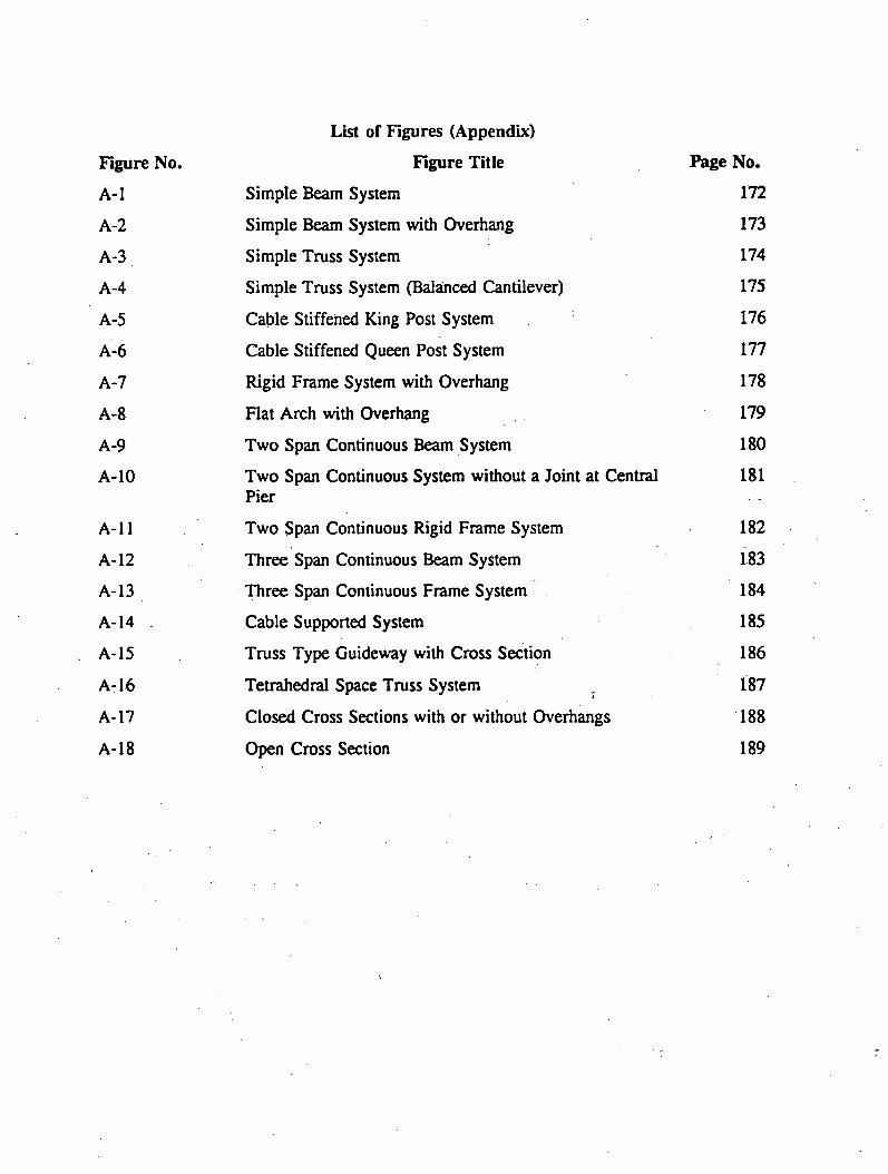
Figure No.A-l
A-2
A-3
A-4
A-5
A-6
k-1
A-8
A-9
A-10
A-l 1
A-12
A-13
A-14 .
A-15
A-16
A-17
A-18
List of Figures (Appendix)
Figure TitleSimple Beam System
Simple Beam System with Overhang
Simple Truss System
Simple Truss System (Balanced Cantilever)
Cable Stiffened King Post System
Cable Stiffened Queen Post System
Rigid Frame System with Overhang
Flat Arch with Overhang
Two Span Continuous Beam System
Two Span Continuous System without a Joint at Central Pier
Two Span Continuous Rigid Frame System
Three Span Continuous Beam System
Three Span Continuous Frame System
Cable Supported System
Truss Type Guideway with Cross Section
Tetrahedral Space Truss System
Closed Cross Sections with or without Overhangs
Open Cross Section
Page No.172
173
174
175
176
177
178
179
180
181
182
183
184
185
186
187
188
189
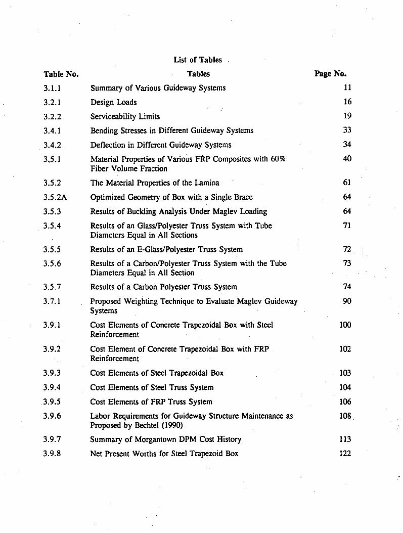
List of Tables
Table No. Tables Page No.
3.1.1 Summary of Various Guideway Systems 11
3.2.1 Design Loads 16
3.2.2 Serviceability Limits 19
3.4.1 Bending Stresses in Different Guideway Systems 33
3.4.2 Deflection in Different Guideway Systems 34
3.5.1 Material Properties of Various FRP Composites with 60% Fiber Volume Fraction
40
3.5.2 The Material Properties of the Lamina 61
3.5.2A Optimized Geometry of Box with a Single Brace 64
3.5.3 Results of Buckling Analysis Under Maglev Loading 64
3.5.4 Results of an Glass/Polyester Truss System with Tube Diameters Equal in All Sections
71
3.5.5 Results of an E-Glass/Polyester Truss System 72
3.5.6 Results of a Carbon/Polyester Truss System with the Tube Diameters Equal in All Section
73
3.5.7 Results of a Carbon Polyester Truss System 74
3.7.1 Proposed Weighting Technique to Evaluate Maglev Guideway Systems
90
3.9.1 Cost Elements of Concrete Trapezoidal Box with Steel Reinforcement
100
3.9.2 Cost Element of Concrete Trapezoidal Box with FRP Reinforcement
102
3.9.3 Cost Elements of Steel Trapezoidal Box 103
3.9.4 Cost Elements of Steel Truss System 104
3.9.5 Cost Elements of FRP Truss System 106
3.9.6 Labor Requirements for Guideway Structure Maintenance as Proposed by Bechtel (1990)
108
3.9.7 Summary of Morgantown DPM Cost History 113
3.9.8 Net Present Worths for Steel Trapezoid Box 122

3.9.9 Net Present Worths for Steel Truss System 123
3.9.10 Net Present Worths for FRP Truss System 124
3.9.11 Net Present Worths for Concrete Trapezoidal Box with Steel Reinforcement
125
3.9.12 Net Present Worths for Concrete Trapezoidal Box with FRP Reinforcement
125
Foreword
"The State-of-the-Art Assessment of Guideway Systems for Maglev Applications"
Project, begun August, 1991, by the Constructed Facilities Center (CFC), involved several
engineering disciplines and eight principal investigators from the Departments of Civil,
Electrical, and Mechanical and Aerospace Engineering, one research engineer, and five graduate
research assistants from the College of Engineering, West Virginia University. This project is
in response to Congressional direction to the Federal Railroad Administration to examine the
feasibility of using nonmagnetic polymer matrix composites, embedment of sensors,
nondestructive testing techniques and manufacturing issues in the development of Maglev
guideways, identifying potential barriers, and proposing strategies to overcome those barriers.
Several innovative guideway systems were developed and the performance and economic
viability of each system were assessed. Furthermore, it should be noted that the guideway
configurations contained herein have been developed to a conceptual level. Further analysis is
required before any of these systems are used in the field.
The information contained in this report is based upon the available Maglev system data
and practices. The CFC researchers have utilized the readily available technical material from
existing literature, which is based upon highway, railway, and other mass transit guideway
system design practices.
Design computations, details, or drawings referenced but not included in this report can
be obtained from the theses prepared by Ralf Wendlik, Phillip Burnside, and Brad Hyre at West
Virginia University in 1992.

EXECUTIVE SUMMARY
The research, conducted through the Constructed Facilities Center, West Virginia
University, described in this report is a comprehensive study to assess the engineering and
economic feasibility of several potential Maglev guideway systems with emphasis on the use of
innovative materials and guideway systems.
This study draws upon the experience of Germany and Japan in order to develop
conceptual guideway systems and to evaluate their technical feasibility. This study examines
both existing guideway systems that were built for Maglev and other mass transit systems and
conceptual innovative guideway systems. An assessment is made of the most promising systems
in terms of performance and cost.
Utilizing parameters such as strength, stiffness, ease of construction and maintenance,
sixteen guideway systems with several cross sections were developed and seven of these were
selected for in-depth analyses. These seven systems are as follows:
1) Trapezoidal concrete box section with conventional steel reinforcement.
2) Trapezoidal concrete box section with Fiber Reinforced Plastic (FRP)
reinforcement.
3) Rectangular concrete box section with conventional steel reinforcement.
4) Trapezoidal steel box section.
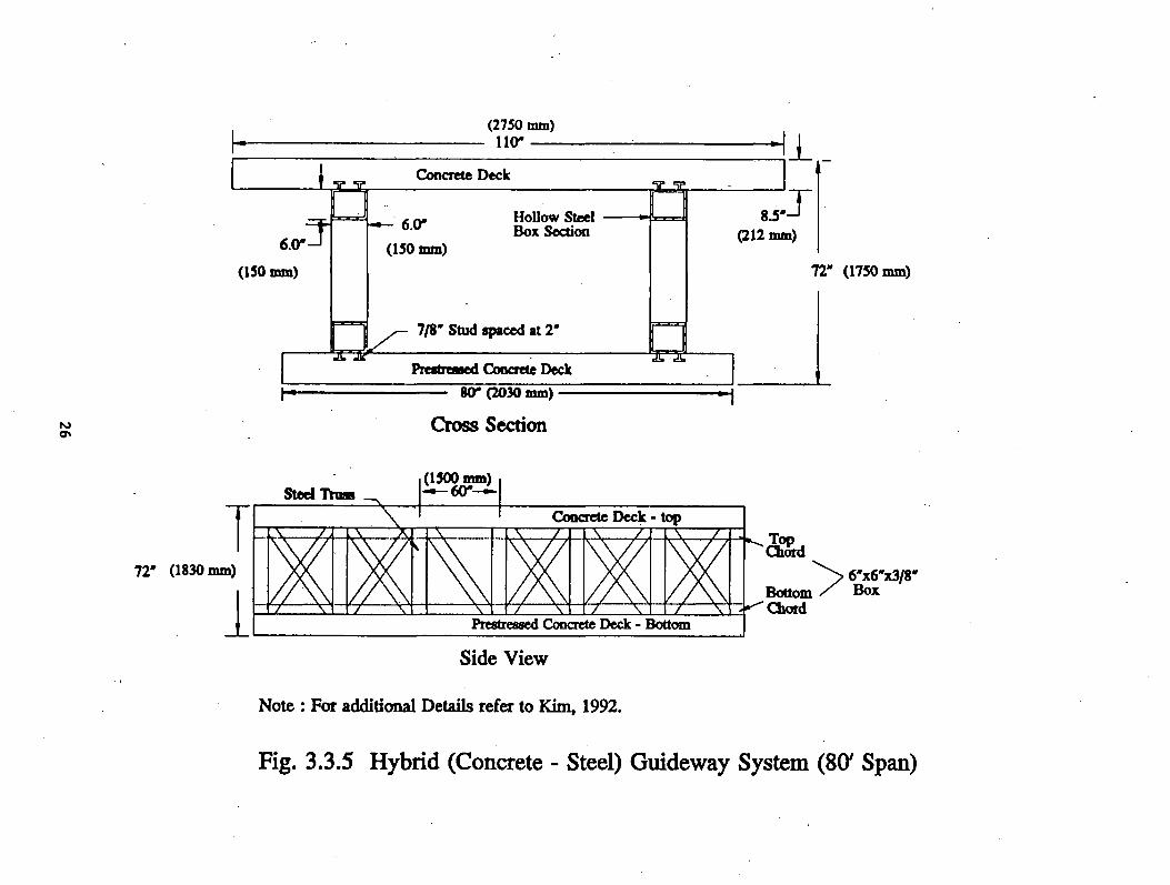
5) Hybrid-system with concrete decking stiffened by steel trusses.
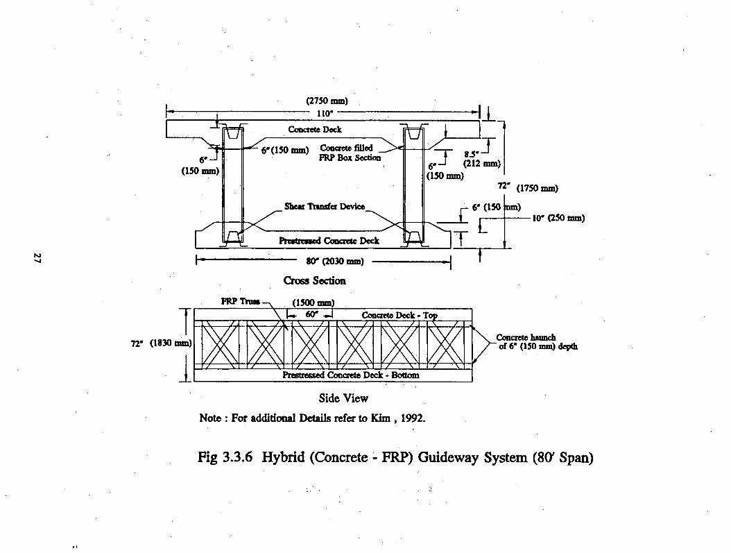
6) Hybrid-system with concrete decking stiffened by concrete filled FRP trusses.
7) All FRP box system.

These systems have been evaluated for their applicability as guideway superstructures
spanning 24.4 to 30.48 m (80 to 100 ft) on the basis of ten load conditions and three
serviceability criteria. Such technical issues as electromagnetic drag forces, sectional efficiency,
feasibility of manufacturing, mass production, and maintainability have been studied along with
feasibility of several nondestructive evaluation techniques to monitor these systems for structural
integrity. In addition, CFC researchers have conducted an economic evaluation of these
guideway systems based upon economic data from various mass transit systems. Researchers
have developed capital costs as well as the labor costs associated with new materials and
construction procedures, a task which proved to be the most difficult step due to the lack of
available data. Limited maintenance cost data have been developed for each guideway system.
Finally, a set of options, including a test plan in terms of laboratory, field experiment
and field demonstration phases, is provided.
1 . 0 I N T R O D U C T I O N
Background
Magnetically levitated (Maglev) high speed ground transportation technologies offer the
potential advantages of lower life-cycle costs, minimal environmental damages, higher energy
efficiency, technology spin-offs through cooperative efforts of various fields of sciences and
engineering, and increased productivity in our construction industry through implementation of
innovative construction techniques, tools, and equipment (Moving America, 1989). In addition,
a fully functional Maglev transportation system offers potential international trade benefits and
relief of traffic congestion. Also, right-of-way acquisition problems may be reduced in terms
of finding open lands near urban areas to expand existing highways, railways, and airports
(Advisory Committee, Benefits of Maglev, 1989). However, several potential drawbacks of high
speed ground transportation systems have to be carefully evaluated before embarking on a full-
scale Maglev construction program. For example, impact of magnetic fields on the
environment, excessive noise levels and human comfort levels due to vibrations at 480 kmph
(300 mph) are just a few of the many potential issues requiring research beyond the levels of
existing information.
Although the United States pioneered the early research and development work on
Maglev high speed ground transportation technologies until the mid-1970s, it has not carried the
research to the construction phase. Japan built a Maglev test facility based on a superconducting
electrodynamic system wherein the magnetic repulsion principle has been adapted (Cortes-
Comeres, 1988). The Germans also built a high speed Maglev test facility in the early 1980s
1

by using an electromagnetic system wherein the principle of magnetic attraction was used.
U.S. federal agencies as well as state and local governments are working together to
assess the engineering, economic, and environmental aspects of Maglev to determine its
feasibility in the U.S. In order to build an appropriate partnership with U.S. industry,
universities, and banking institutions, some preliminary engineering and economic issues related
to Maglev would have to be identified and prioritized (National Maglev Initiative, 1990). Major
decisions, including options for future United States Maglev development, can be made only
after collecting and synthesizing appropriate engineering, environmental and economic data, andI
evaluating the data with reference to other high speed transportation system alternatives.
Problem Statement
In August 1991, the CFC received a research contract through the National Maglev
Initiative (NMI) to conduct research into the development of innovative Maglev guideway
systems. The primary purpose of the study is to examine innovative design, construction, and
operation and maintenance approaches that can significantly improve the life-cycle costs of
elevated guideway systems. Research relative to guideway systems is important because a large
fraction of the initial capital costs (up to 80%) of an overall total Maglev system is spent on the>
guideway.
The successful implementation of Maglev systems in this country will depend to a great
extent on the feasibility of constructing safe and economical guideways. Maglev vehicles have
unique requirements which make them different from other mass transportation systems. Some
of these requirements impose greater demands on cost and/or serviceability than the tracked
2
guideways of lower-speed conventional rail systems. For example, the close surface tolerances
required by Maglev mean higher construction and maintenance costs. Other features of Maglev
systems may ease guideway maintenance requirements, e.g., fewer constraints on material
durability due to lack of frictional contact surfaces. In any case, the unique features of Maglev
systems call for unique approaches to the development of the guideways.
Areas investigated as part of this contract include:
1) use of non-conducting materials such as polymer matrix composites;
2) evaluations of nondestructive testing approaches to monitor guideway condition;
3) evaluation of contemporary construction techniques; and
4) analysis of life-cycle cost analysis to determine the economic impact of innovative
materials on Maglev guideways.
Polymer matrix composites appear to offer a solution to potential problems arising from
electromagnetic forces. Similarly, modem nondestructive evaluation (NDE) techniques and
construction methods have to be carefully researched for their implementation during guideway
construction in-service operations and for their economic benefits. We believe that the
systematic evaluation of new materials, modem NDE and construction methods, and cost-benefit
aspects for Maglev systems will lead to an economical guideway system.
This report summarizes the work on Maglev guideways that has been carried out at the
CFC over the past year. Some of the information contained herein is summary-level material
from theses written by graduate research assistants (Burnside, 1992, Hyre, 1992, and Wendlik,
1992). Additional technical information from these theses may be obtained from the CFC.
3
2 . 0 O B J E C T I V E S
The specific objectives of this project are to:
1) Examine the designs of existing or proposed Maglev guideways with emphasis on
performance requirements.
2) Assess the state-of-the-art of nonconducting structural materials in relation to
conventional materials, and assess the potential use of nonconducting materials
for Maglev guideways.
3) Assess the feasibility of utilizing prototype composite systems.
4) Assess the modem construction methods for Maglev guideway construction and
diagnostic and monitoring techniques to determine the guideway integrity, and
determine possible impediments to their implementation.
5) Analyze costs and economic impact of objectives 2 through 4 on Maglev
guideway systems.
6) Select several of the most promising materials and composite guideway systems
for further testing and evaluation, and develop a test plan to determine their
technical viability.
To meet these objectives, we have examined the designs of existing high speed
transportation guideway systems as well as those proposed for Maglev guideways which use
structural steel and conventional reinforced concrete as their major load-bearing members.
Emphasis has been given to the design and performance criteria of guideway systems, life-cycle
costs, use of new guideway materials, and efficient in-service data collection relating to distress
and aging phenomena.
4

In addition, innovative, mass-produced, nonmagnetic materials have been examined for
their potential use in the Maglev guideway systems. Limitations and costs involved with the
development of these innovative materials have also been addressed. These nonmagnetic
materials have been examined because of the generation of electromagnetic fields by a Maglev
system. These fields may interact with structural steel guideways and control systems, resulting
in impacts on ride comfort and energy consumption.
Nondestructive evaluation techniques, including data collection, are examined with a view
towards accurate predictions of future maintainability of guideways and possible improvements
in construction and rehabilitation techniques.
5

3.0 FEASIBILITY ASSESSMENT OF EXISTING GUIDEWAY
SYSTEMS ADAPTABLE TO MAGLEV APPLICATIONS
3.1 Review of Existing Guideway Systems and Their Potential
Applicability to Maglev Guideways
The guideways for Maglev as well as other mass transit systems are typically constructed
of steel or concrete; representative systems are shown in Figures 3.1.1. through 3.1.4. For
example, precast concrete double tee or box sections are used in concrete construction (Figure
3.1.1.). Similarly, two wide flange (plate girder) sections or steel box sections supporting a
concrete deck are used in steel guideway construction (Figure 3.1.2). The trapezoidal cross
sectional shapes with overhangs are used for existing Transrapid Maglev guideway (Figures
3.1.3 and 3.1.4) because they offer greater resistance and stability when subject to lateral as well
as torsional loads, which are predominant in the design of a Maglev system.
Other systems:
In addition to the Japanese (Masada, et al., 1984) and the German systems (Transrapid,
1991), several other nations (Wendlik, 1992) have made an effort in advancing the Maglev
technology.
The first magnetically levitated system opened for public transportation was constructed
and developed by British Rail in Birmingham, England (Mustow, 1984). This "People Mover"
runs on a 620 m (2034 ft.) long track connecting the town of Birmingham to its train station and
6
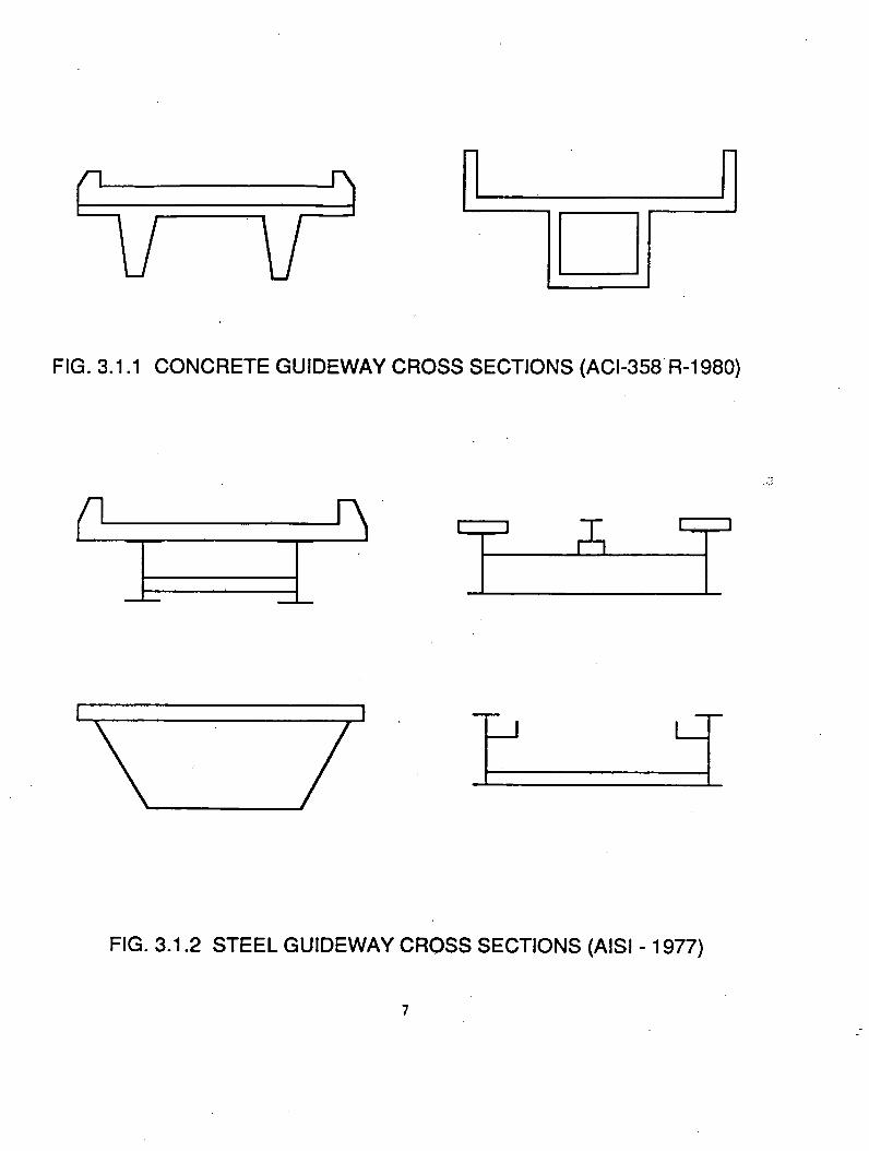
FIG. 3.1.1 CONCRETE GUIDEWAY CROSS SECTIONS (ACI-358 R-1980)
FIG. 3.1.2 STEEL GUIDEWAY CROSS SECTIONS (AISI -1977)
7

FIG . 3 .1 .3 S T E E L G U ID E W A Y SE C T IO N
F O R T R A N S R A P ID SY STEM
FIG . 3 .1 .4 C O N C R E T E G U ID E W A Y SE C T IO N
F O R T R A N S R A P ID SY ST E M
8

airport. The 6 m (19.7 ft.) long vehicle cabin contains six seating and 26 standing
accommodations. The Birmingham Maglev utilizes an electromagnetic levitation system and a
linear induction motor (LIM) for propulsion. The vehicle cruises at a speed of 40 kmph
(25 mph), separated from the guideway by an air gap of 15-20 mm (0.6-0.8 in).
In Canada, an electrodynamic system has been proposed using superconducting magnets
(SCM) for levitation and a linear synchronous motor (LSM) for propulsion. This high speed
Maglev proposal was developed for a maximum cruising speed of 483 kmph (300 mph).
France and Russia have been making efforts in developing their own Maglev
technologies. Because they are at an early stage of their mass transit project, their progress is
still limited. An overall summary of various Maglev systems is given in Table 3.1.1.
Outlook for Maglev in the USA:
The research on the basic principles on magnetic levitation and propulsion systems was
initiated in the U.S. in the late sixties and early seventies, but by 1975 most government-
sponsored activities in that field were suspended. Limited research efforts on single-sided linear
induction motors (SLIM) were made beyond 1975; but even these efforts were terminated due
to monetary constraints and lack of public support.
9

In the 1980s, feasibility studies were performed by the Budd Company in conjunction
with Transrapid International on the Las Vegas-Los Angeles corridor, using the Transrapid 06
or alternative systems, the JNR-Maglev and the French TGV (Budd Company, 1983). The
studies were based on traffic density, environmental aspects, financing, system evaluation,
investment costs, and time scheduling. The results concluded that an EMS system is most viable
for the Las Vegas-Los Angeles corridor. Other suitable routes for a high-speed system, such
as the Boston-New York-Washington, D.C., connection or the Pennsylvania corridor between
Pittsburgh and Philadelphia, are at a discussion stage.
As a minimum, Maglev guideways are to support, levitate, guide and propel vehicles at
speeds up to 483 kmph (300 mph). Therefore, any Maglev guideway system to be built in the
United States needs special provisions not found in the design and construction of typical
American highway or railway bridges. Maglev guideway construction, so far, is predominantly
a single beam construction because single beam construction with trapezoidal cross section is
easier to build and easier to meet design tolerances (Hilliges, 1981) than other complex shapes.
Even though multi-span guideway systems were developed by the authors in the conceptual stage
(Appendix A) for American applications, herein the multi-span systems were not developed
further because of possible difficulties in maintaining such systems for differential settlements
(GangaRao, 1981).
Ride quality plays a crucial role in guideway design and construction of an American
system. Higher levels of ride comfort can be achieved by properly accounting for the following
in guideway design and construction: geometric design, camber and deflection limits for service
loads, differential movements of piers, construction tolerances, surface roughness, and
construction and maintenance joints. -
10

T a b le 3 . 1 . 1 . S u m m a r y o f V a r io u s G u id e w a y S y s t e m s
G erm an Jap an ese B ritish C anadian
System Magnetbahn, GmBH TransrapidInternational
High Speed Surface Transport (H SST)
Japanese National Railway (JNR)
British Rail Atherton, D .L .
Existing Track Berlin, in operation Emsland, 3 1 .4 km (19 .5 m ile) test track
Demonstrated at several expositions
M iyazaki, 7 .1 km (4 .4 m ile) test track
Birmingham, 0 .6 km (0 .4 m iles) in operation
Proposed
Year Built M ay, 1987 1984 1985 1980 February, 1985 N o full scale guidew ay was built
Levitation Attraction, using permanent magnets
Attraction,electrom agnetic
Attraction,electrom agnetic
R epulsion, using passive coils & SC M s
Attraction,electrom agnetic
R epulsion, using SCM s
Propulsion Electrom agnetic, using LSM , long-stator
Electrom agnetic, using LSM , long-stator
Electrom agnetic, using LIM , short-stator
Electrodynam ic, using LSM & SC M s
Electrom agnetic, using LIM
Electrodynam ic,LSM
Lateral G uidance G uide w heels Electrom agnetic Electromagnetic Electrodynam ic Electrom agnetic Electrodynamic
Air Gap 11-26 mm (0 .4 3 -1 .0 2 in) 10 mm (0 .3 9 in) 11 mm (0 .43 in) 100 mm (3 .9 4 in) 15-20 mm (0 .5 9 -0 .7 9 in)
150 mm (5 .91 in)
Gap M aintenance Mechanical Electronic Electronic Electronic Electronic Electronic
M agnetic Field 1175 mT (11750 gauss) @ track
< 0 .5 m T (5 gauss) in compartment
N ot available 10 - 20 m T (100 -200 gauss) in compartment
.5 mT (5 gauss) in compartment
20 m T (200 gauss)- floor level 8 mT (80 gauss)- seat level
Cruising Speed 88.5km ph (55 mph)
4 9 8 .8 kmph (310 mph)
9 6 .5 ,1 9 3 ,2 8 9 .6 kmph (6 0 ,1 2 0 ,1 8 0 mph)
4 1 8 -4 9 8 .7 kmph(260 - 310 mph) Runs onw heels until 100 kmph
40 kmph (25 mph)
4 8 2 .7 kmph (300 mph)
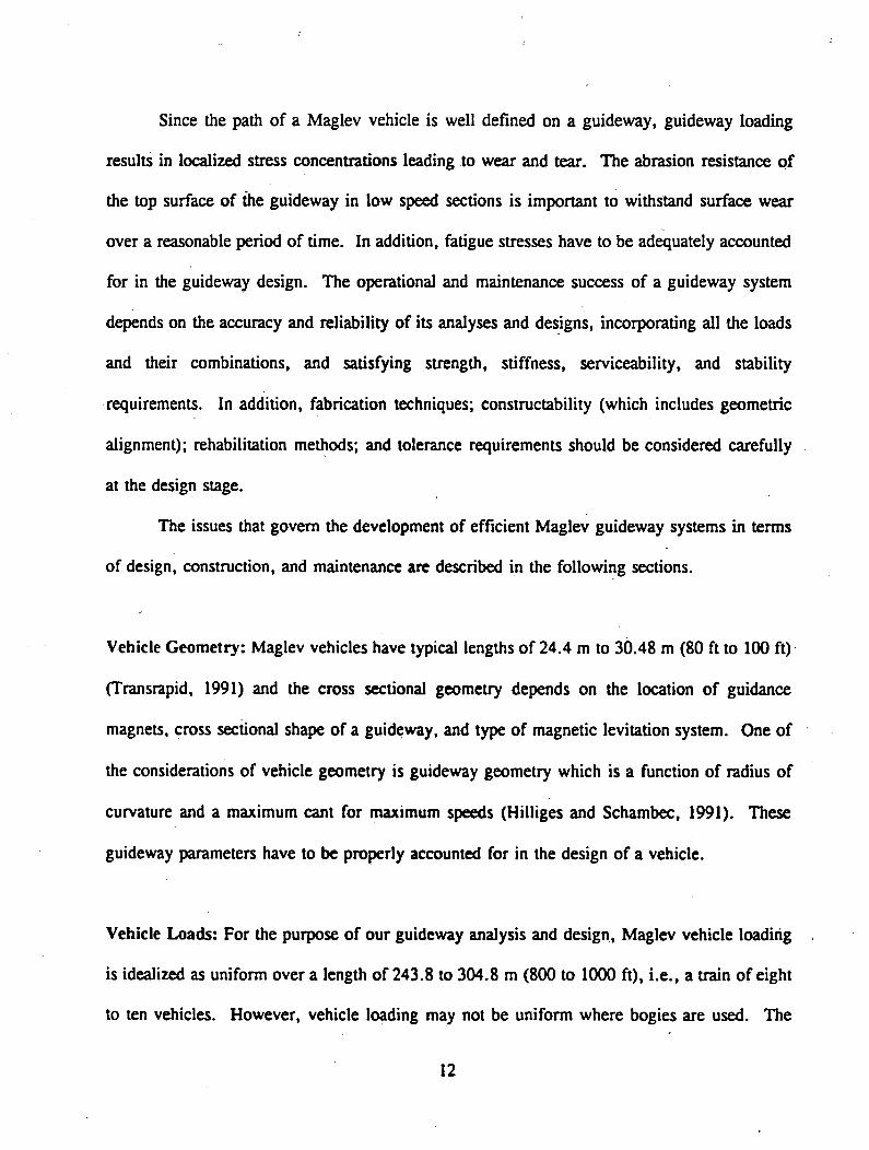
Since the path of a Maglev vehicle is well defined on a guideway, guideway loading
results in localized stress concentrations leading to wear and tear. The abrasion resistance of
the top surface of die guideway in low speed sections is important to withstand surface wear
over a reasonable period of time. In addition, fatigue stresses have to be adequately accounted
for in the guideway design. The operational and maintenance success of a guideway system
depends on the accuracy and reliability of its analyses and designs, incorporating all the loads
and their combinations, and satisfying strength, stiffness, serviceability, and stability
requirements. In addition, fabrication techniques; constructability (which includes geometric
alignment); rehabilitation methods; and tolerance requirements should be considered carefully
at the design stage.
The issues that govern the development of efficient Maglev guideway systems in terms
of design, construction, and maintenance are described in the following sections.
Vehicle Geometry: Maglev vehicles have typical lengths of 24.4 m to 30.48 m (80 ft to 100 ft)
(Transrapid, 1991) and the cross sectional geometry depends on the location of guidance
magnets, cross sectional shape of a guideway, and type of magnetic levitation system. One of
the considerations of vehicle geometry is guideway geometry which is a function of radius of
curvature and a maximum cant for maximum speeds (Hilliges and Schambec, 1991). These
guideway parameters have to be properly accounted for in the design of a vehicle.
Vehicle Loads: For the purpose of our guideway analysis and design, Maglev vehicle loading
is idealized as uniform over a length of 243.8 to 304.8 m (800 to 1000 ft), i.e., a train of eight
to ten vehicles. However, vehicle loading may not be uniform where bogies are used. The
12

vehicle loading depends upon vehicle geometry, seating capacity, and any dead weight of
magnets or other equipment in the vehicle. Vehicle induced dynamic loads, electromagnetic
forces, and aerodynamic drag forces depend upon vehicle speeds, number of vehicles in a train,
and vehicle shape.
Vehicle-guideway Interaction: Vehicle-guideway interaction analyses are required to establish
the live load amplification factor (impact factor) and dynamic characteristics of the guideway.
The vehicle-guideway dynamic characteristics relate to the human comfort criteria, vehicle
stability, noise levels, and guideway maintainability.
Vehicle Braking: Vehicle braking is an important consideration. Normal braking is controlled
by a linear motor by reversing the direction of the current in the motor. Emergency braking
may be achieved by using skids to take advantage of friction between the vehicle and guideway.
Substructure and support bearings may be most severely affected by the vehicle braking;
therefore, special bearing materials and innovative joint detailing have been developed to
minimize maintenance.
Lateral Guidance: A lateral guidance mechanism is very important for the maintenance of
vehicle position on the guideway. A variety of guidance systems have been used depending
upon the geometry of the guideway and the vehicle (Transrapid, 1991, Schwindt and Kindmann,
1990, M-Bahn, 1990). Accurate installation, strict tolerances, and maintenance of these
guidance magnets are essential, especially for high vehicle velocities. In addition, lateral
guidance should be designed to resist the loads caused by horizontal wind forces, centrifugal
13
forces, and cornering effects. The guidance mechanisms should be adjustable to improve the
ride quality. Switching is another important consideration in the design and construction of a
guideway. Careful guidance mechanisms should be planned at locations where switching takes
place so that the vehicle can transit from one guideway to another with a minimum effect on ride
quality.
Environmental Loads: Environmental loads such as earthquakes, wind, ice, snow, and
temperature are accounted for using normal design practice. The impact of some climatic effects
such as ice or snow may be minimized by heating guideways through electrically heated cables
or by supplying heated fluid through pipes embedded in a guideway. The heated fluid concept
has been successfully adapted by the Morgantown People Mover guideway system (AISI, 1977).
Economic Considerations: The capital investment required for guideway systems is high;
estimates are on the order of $12 to $15 thousand per track meter (3.3 ft) in 1990 dollars
(National Maglev Initiative, 1990). Factors that influence the capital costs are soil conditions,
site acquisition, site accessibility during construction, availability of manpower and equipment,
materials and technical know-how. To optimize operational costs, a guideway system should
be designed to minimize traffic interruptions (Hyre, 1992). A single-lane guideway system is
narrow enough that it can be built using a span by span construction concept and prefabricated
modular units (Hilliges, et.al., 1981). From the system response viewpoint, dual guideways
may better serve their purpose by separating them into two halves. Modular design and
construction concepts are ideal for building repetitive super- and sub-structural systems. The
superiority of construction quality and time savings of modular construction were established
14

*
through recent construction experience with modular timber bridges (GangaRao, 1990). The
benefits of mass production and modularization are: (1) reduction of on site manual labor
requirements and time savings (40-50% of the input in conventional construction); (2) faster
construction process (reduction of 15-20 activities with conventional method to 10-12 activities
with modularized system); and (3) higher quality modules through careful choice of materials
and strict quality control (Warszawski, 1990).
3.2 DESIGN LOADS AND SERVICEABILITY LIMITS:
The ten different design loads and four serviceability limits shown in Tables 3.2.1 and
3.2.2, respectively are based on (1) information in the literature; (2) experience of CFC
professionals, and (3) discussions with professionals having experience in guideway design and
construction.
3.3 IDENTIFICATION AND DEVELOPMENT OF INNOVATIVE GUIDEWAY
SYSTEMS FOR MAGLEV APPLICATIONS
Structural configurations were developed based upon the parameters: (1) strength; (2)
stiffness; (3) manufacturing; (4) erection; (5) unit weight; (6) maintenance; (7) joint
location; (8) sectional efficiency; (9) materials; (10) depth; (11) super-and sub-structure
integrity; (12) single vs. continuous spans; (13) construction tolerances; and (14) substructure
height. Sixteen guideway system concepts were developed. Schematic drawings for the sixteen
systems are presented in Appendix A. The guideway systems consists of beam and truss type
15

Table 3.2.1 Design Loads
N o. T ype o f Load Load R eference
1 Dead Loads
T ype 1. Trapezoidal C one. Box w ith Steel 3 6 .4 2 kN /m H illiges, et a l., 1991Rebars (F ig . 3 .3 .1 ) (2 5 0 0 lb/ft)
T ype 2 . Trapezoidal C one. Box w ith FRP 3 6 .4 2 kN /m H illeges, et a l., 1991Rebars (F ig . 3 .3 .2 ) (2 5 0 0 lb/ft)
Type 3 . Rectangular C one. Box w ith Steel 4 1 .5 9 kN /m W endlik , 1992Rebars (F ig 3 .3 .3 ) (2855 lb/ft)
T ype 4 . A ll Steel Trapezoidal Box (F ig . 3 .3 .4 ) 11.65 kN /m (8 0 0 lb/ft)
Schw indt & Kindman 1990
T ype 5 . H ybrid-C one. D eck w ith Steel Truss 3 2 .0 5 kN /m Kim, et a l., 1992(F ig . 3 .3 .5 ) (2200 lb /ft
T ype 6 . H ybrid-C one. D eck w ith FRP Truss 4 0 .7 9 kN /m Kim, et a l., 1992(F ig . 3 .3 .6 ) (2 8 0 0 lb/ft)
T ype 7 . A ll FRP Box - 3 .7 4 kN /m (2 6 0 lb/ft)
Burnside, 1992
2 L ive Load 2 4 .7 6 kN /m (1 7 0 0 lb /ft)
Transrapid, 1991
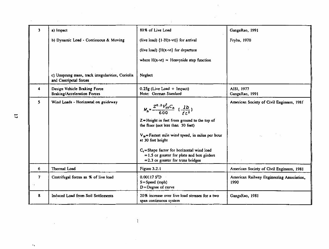
3 a) Impact
b) Dynamic Load - C ontinuous <Sc M oving
c) Unsprung m ass, track irregularities, C orio lis and Centripetal forces
8096 o f Live Load
(live load) { l-H (x -v t)} for arrival
(live load) {H (x-vt} for departure
w here H (x-vt) = H eavyside step function
N eglect
G angaRao, 1991
Fryba, 1970
4 D esign V ehicle Braking Force 0 .2 5 g (L ive Load + Impact) AISI, 1977Braking/Acceleration Forces Note: German Standard G angaRao, 1991
5 Wind Loads - H orizontal on guidew ay. C . , l b ,
h 6 0 0 f t 3
Z = Height in feet from ground to the top o f the floor (not less than 30 feet)
V M= Fastest m ile w ind speed, in m iles per hour at 30 feet height
Ck= Shape factor for horizontal w ind load = 1.5 or greater for plate and box girders = 2 .3 or greater for truss bridges
American Society o f C ivil Engineers, 1981s
6 Thermal Load Figure 3 .2 .1 Am erican Society o f C ivil Engineers, 1981
7 Centrifugal forces as % o f live load 0 .0 0 1 1 7 S ^S = Speed (mph)D = D egree o f curve
Am erican R ailway Engineering A ssociation, 1990
8 Induced Load from Soil Settlem ents 20% increase over live load stresses for a tw o span continuous system
G angaRao, 1981
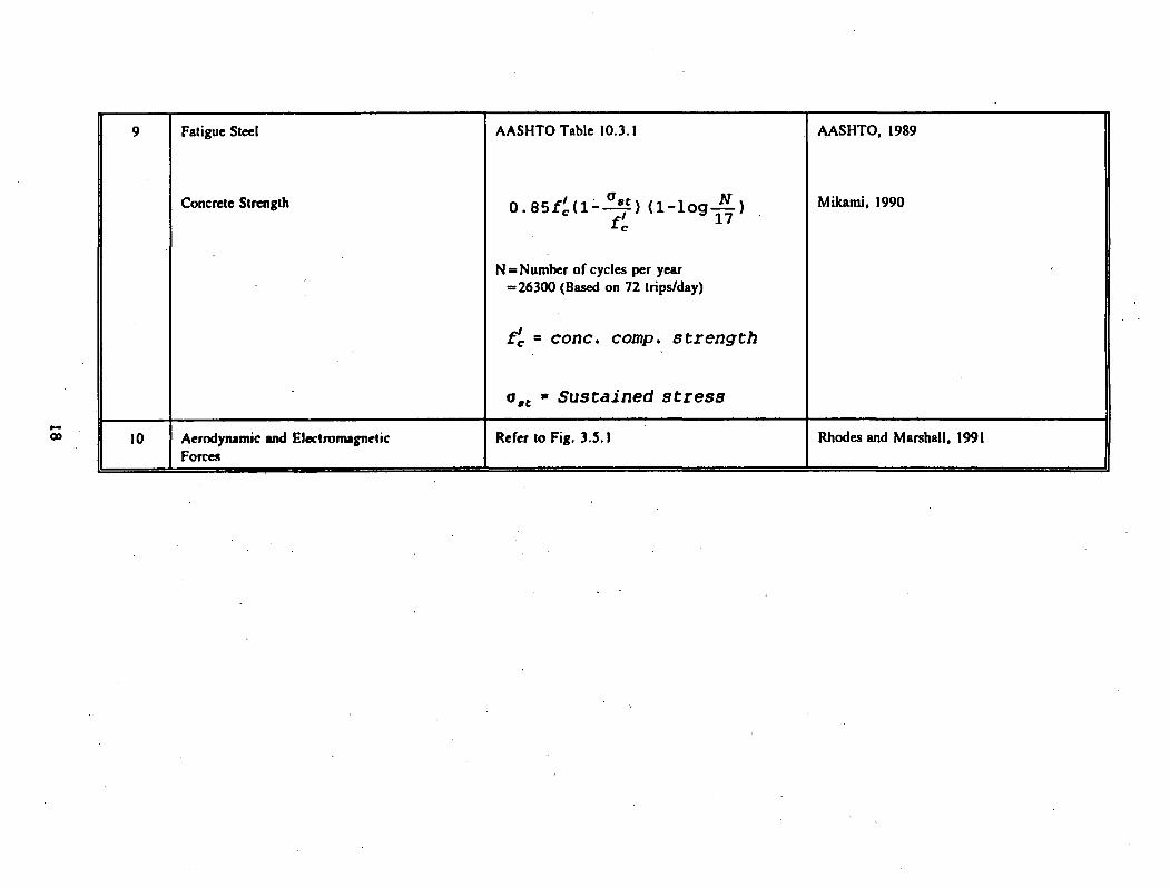
9 Fatigue Steel A A SH TO Table 10.3.1 A A SH T O , 1989
Concrete Strength 0.8 5 /p (1 - ) (1 -1 og ■— )
N = Num ber o f cycles per year = 2 6 3 0 0 (Based on 72 trips/day)
f'c = cone. comp, strength
M ikam i, 1990
oBt • Sustained stress
10 Aerodynam ic and Electrom agnetic Forces
Refer to F ig . 3 .5 .1 Rhodes and M arshall, 1991

Table 3.2.2 Serviceability Limits
N o. Serviceability T ype Limit R eference
1 Vertical D eflection (Span length)/2000 GangaRao, 1991
2 Longitudinal Angular D istortion (D ifferential Settlem ent/Span Length)
0 .0 0 5 for Sim ple Supports 0 .0 0 4 for Continuous Structures
G angaRao, 1981
3 Human tolerable leve ls for noise 4 0 -5 0 dBA (inside the veh icle) Merritt & A m brose, 1990; Transrapid, 1991
4 Human response to vibration in am plitude 0 .1 3mm(0 .0 0 5 in) am plitude ® 3 Hz
a = am plitude= (D I)5,(2IIfb)J
W hereD l = Impact Factor
D l - 0 .1 5 + a
a = V / 2 f bL
V o V ehicle Speed
e- _ n EbI b b ' 2L2N m
b, = static deflections computed w ith a transverse load distribution factor o f 0 .7
Efclb = Stringer flexural rigidity
L = span
m = m ass/unit length o f stringer p lus a portion o f -the deck
W alker, 1971
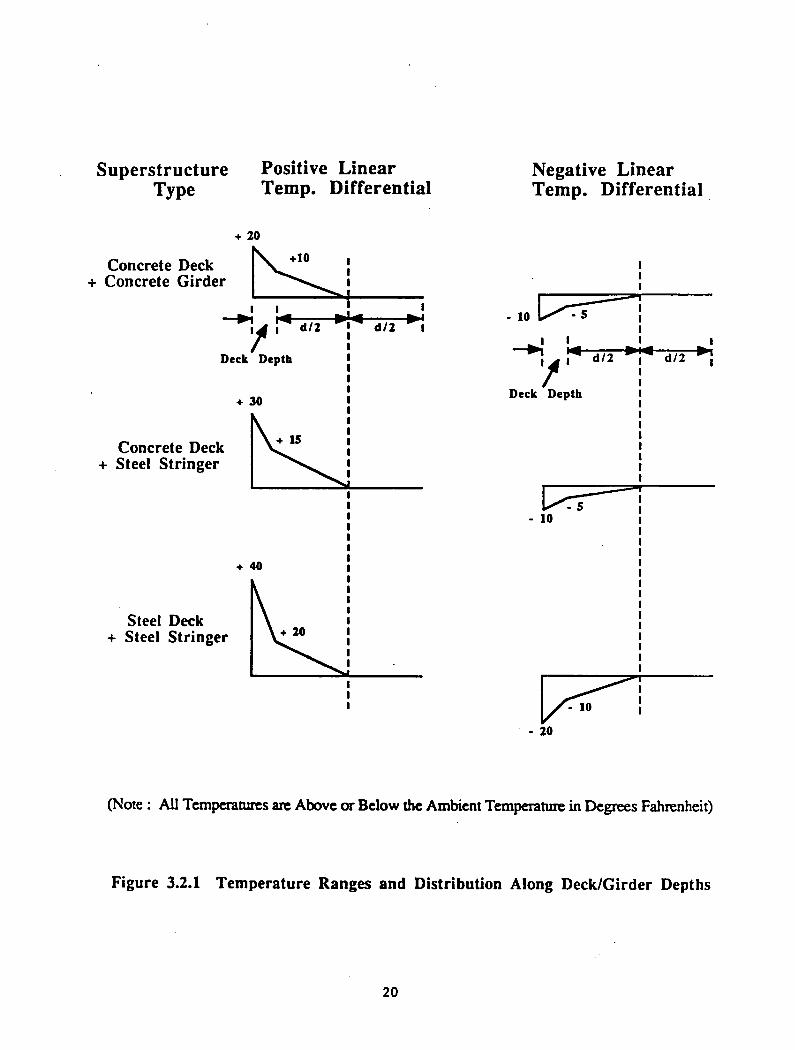
S u p erstru ctu re P ositive L in earT ype T em p . D iffer en tia l
N egative L inear T em p . D iffer en tia l
+ 20
(Note : All Temperatures are Above or Below the Ambient Temperature in Degrees Fahrenheit)
Figure 3.2.1 Temperature Ranges and Distribution Along Deck/Girder Depths
2 0

configurations, single span systems with and without overhangs, and continuous spans with and
without moment transfer capability between the super- and sub-structural components. Guideway
systems stiffened with post-tensioned cables were also considered in our analysis for longer
spans, i.e., up to 92 m (300 ft.).
Of the sixteen conceptual systems, seven configurations were selected for a detailed
assessment of design, construction, and maintenance efficiency and a basis of selection is
described in Appendix A of this report. The seven guideway systems, shown in Figures 3.3.1
through 3.3.7 are as follows: (I) trapezoidal concrete box with conventional steel
reinforcement, (2) trapezoidal concrete box with FRP reinforcement, (3) rectangular concrete
box, (4) all steel trapezoid box, (5) hybrid system with concrete upper and lower decking
stiffened by steel truss members, (6) hybrid system with concrete upper and lower decking
stiffened by FRP truss members and (7) an all FRP box section.
The guideway truss systems with steel and/or FRP members utilize less material and are
easier to erect. Furthermore, erection of modular guideway systems with FRP members
becomes quicker because FRP members are five to six times lighter than steel. However, the
FRP truss joint design and detailing need special attention. To utilize the higher strength of
FRPs in an efficient manner and to increase the stiffness of a structural system, the modular
truss configuration using FRP members was selected for further studies and additional details
are provided in Section 3.4. The conventional in-situ construction practices are possible at the
expense of quality of workmanship and economics (Warszawski, 1990).
Special attention is focused on the trapezoidal and rectangular box sections because they
have been typically used for steel, concrete, and hybrid materials. The trapezoidal and
rectangular sections are efficient in resisting loads in lateral, transverse, and longitudinal
directions under bending and torsion. Shallower depths can be achieved through these
21

8.5"j- (212 mm)
Note: Not shown is the anchorage zone reinforcement, #10 stirrups @ 4" (100 mm) within critical anchorage zone, which is h/2 - 36" (900 mm). For details, refer to Wendlik, 1992.
Fig. 3.3.1 Cross sectional Details - Concrete Maglev Guideway System with steel rebars
# 4 @ 18" (450 mm)
Note: Not shown is the spiral reinforcement cage for the tendon anchorage zone. For additional details, refer to Wendlik, 1992.
Fig. 3 .3 .2 Cross Sectional D eta ils - Concrete M aglev G uidew ay System w ith FRP Rebars
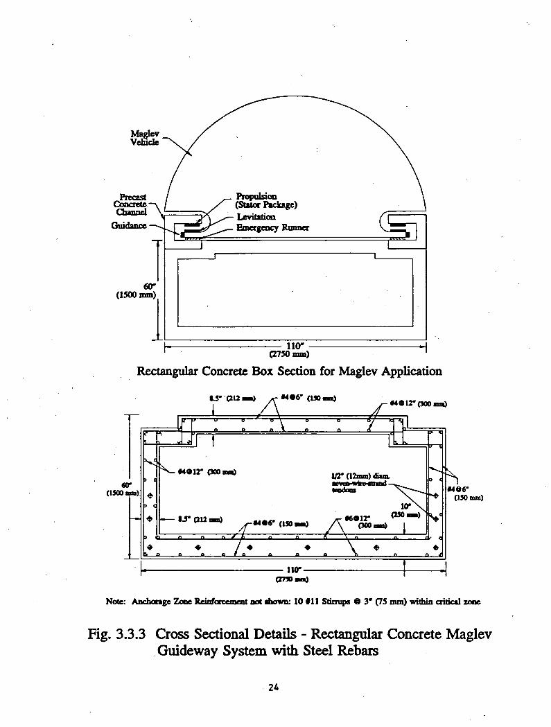
Rectangular Concrete Box Section for Maglev Application
Note: Anchorage Zone Reinforcement not shown: 10 #11 Stirrups @ 3* (75 mm) within critical zooe
Fig. 3.3.3 Cross Sectional Details - Rectangular Concrete Maglev Guideway System with Steel Rebars
24
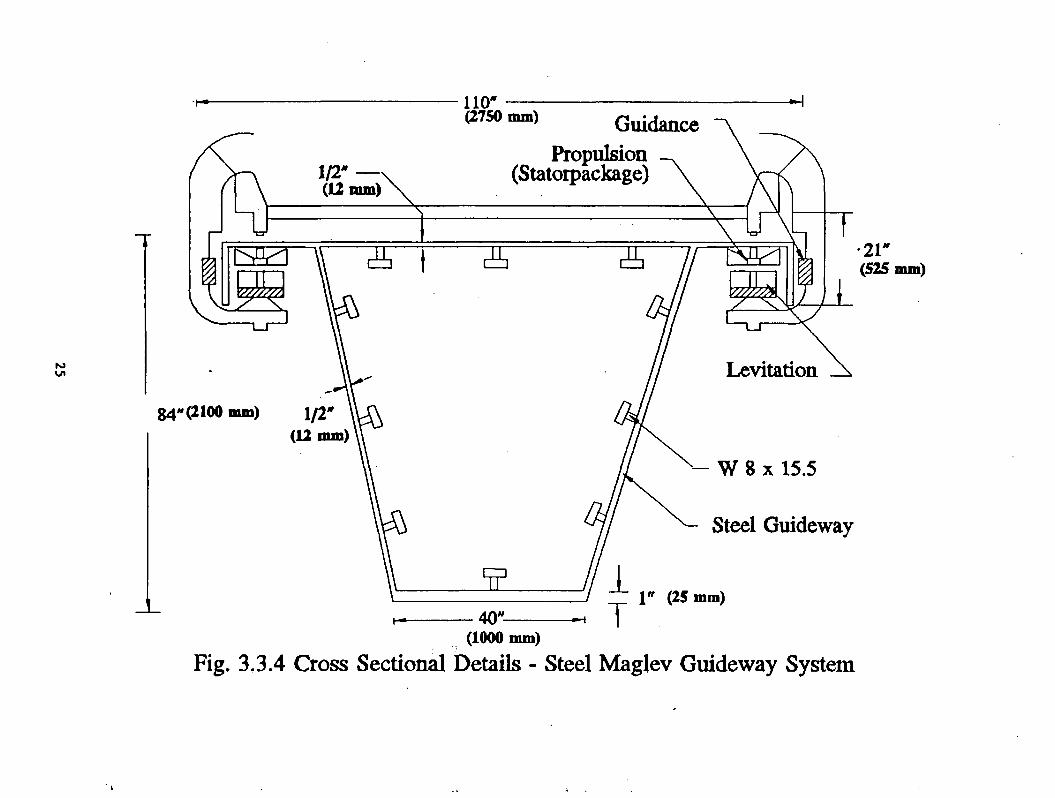
Fig. 3.3.4 Cross Sectional Details - Steel Maglev Guideway System
•21*(525
Chord
BottomChord
6”x6*x3lt*Box
Note : For additional Details refer to Kim, 1992.
Fig. 3.3.5 Hybrid (Concrete - Steel) Guideway System (80* Span)
K>-Vj
Note : For additional Details refer to Kim , 1992.
Fig 3.3.6 Hybrid (Concrete - FRP) Guideway System (807 Span)

(ISO wm\)
F i g . 3 . 3 . 6 A T R U S S M E M B E R C O N N E C T I O N D E T A I L

Cellular section
rig. 3.3.7 All FRP cellular box system.
SUPPORT FIBER Depth FI (in)
Simply Supported Carbon 93.7
Clamped - Clamped Carbon 42.2
Simply Supported Glass 92.5
Clamped - Clamped Glass 55.9
29

configurations, provided that local and global buckling are prevented by using web and flange
stiffeners. Single span systems were studied from design, manufacturing and erection points of
view. Additional details on design and erection can be obtained from Wendlik’s report
(Wendlik, 1992).
Single span systems can be converted to continuous span systems in the field through post
tensioning or other joining techniques where nonprestressed rigid joints can be achieved in the
field. Through continuity of multiple span systems, nearly uniform moment resisting capability
can be attained in all spans. Multiple span systems have a smaller number of discontinuous
joints than a single span system, leading to improved ride quality.
The in-plane stresses induced by acceleration, braking, and thermal forces should be
properly accounted for in the design. Therefore, full moment transfer capacity has to be
incorporated in the guideway design to effectively transfer acceleration and braking forces from
the guideway to the supports. The moment transfer capability between super- and sub
structures has been researched in multiple guideway systems for their structural efficiency in
transferring vertical and horizontal loads and found to be more efficient than single span
guideways. In addition, joint locations (super- and sub- structure junction or sub-structure and
footing junction) and joint types (roller, hinge, or rigid) have to be evaluated to optimize the
guideway system efficiency.
The span length of 24.4 m (80 ft.) has been selected for this analysis. In continuous
multiple span cases, because of redistribution of support and center span moments, the design
span length can be increased to 30.5 m (100 ft.) or more without changing the cross sectional
properties of a single span system designed for 24.4 m (80 ft.) spans. The span length may
30

have to be increased in valleys to limit substructure height and to minimize the overall cost of
a system. Even though cable stiffened superstructure! guideway systems may turn out to be
more economical than conventional guideways, additional details are not developed herein
because of uncertainties in terms of long term performance of anchorage details, aerodynamic
drag forces and torsional instability.
3.4 PERFORMANCE ASSESSMENT FOR MAGLEV GUIDEWAY SYSTEMS.
Two basic design approaches - working stress and load factor design - are used by the
structural designers for bridges, buildings, and many other types of structures. For a Maglev
elevated guideway system, the working stress design approach is recommended because the
design is controlled by deflection limits rather than the strength limits.
The stresses and deflections were computed for the seven selected systems based on the
conventional elastic design method. The finite element method was used to analyze some of the
guideway systems. The stresses and deflections for all seven systems are shown in Tables 3.4.1
and 3.4.2. The live load (LL) deflection limit of 7.5 mm (0.25 in) for a 24.4 m (80 ft.) span
and a 24.6 kN/m (1700 lb/ft) load is set for all three systems. The calculated stresses in all
three systems are lower than the allowable stresses of the different materials. The dead loads
(DL) of steel. Concrete, and hybrid systems are about 11.65 (800), 36.42 (2500), and 32.05
(2200) to 40.8 (2800) kN/m (lb/ft.), respectively. The merits of each system are further
investigated from the viewpoint of modular construction. In addition, detailed designs of
superstructure! systems with FRP truss members and FRP boxes were developed by Burnside,
1992, to compare their design efficiency, constructability, and cost competitiveness with
conventional guideways.
31

3.5 POTENTIAL USE OF INNOVATIVE MATERIALS
Applications of fiber reinforced plastics (FRPs) in non-structural components of vehicles
are well known (Green and Bisavnsin 1986, 1987, and Green, 1990). Also, additional
information on the structural applications of FRP materials can be obtained through several
references (Green and Bisavnsin, 1986, 1987, and Green, 1990; Ballinger, 1990, Smallowitz,
1985). The additional structural applications deal with FRP bridges, gable frames, industrial
buildings and others. The technical literature on FRP bridges and frames can be utilized in fine-
tuning the design computations of strength and stiffness for FRP Maglev guideway systems.
Additional details on applications are given in Section 3.5.2. We concentrated our effort on the
evaluation of FRPs for load carrying structural applications in Maglev guideway systems.
3.5.1 Evaluation of Magnetic Field Interference
While in motion, a magnetically levitated vehicle induces eddy currents in metal which
is within the magnetic field of the lift magnets (Rhodes and Mulhall, 1981). These undesirable
eddy currents cause electromagnetic forces that resist forward motion and lead to increased
guideway component temperatures. Such temperature increases become a source of energy loss
for a Maglev system. This particular type of energy loss has been termed the magnetic drag
force on the vehicle.
The theoretical determination of the magnetic drag force is a very complex problem
which varies greatly from system to system. Factors which affect the magnetic drag force are
as follows: the type of system (i.e., electrodynamic versus electromagnetic suspension);
configuration of magnets, number of windings, current through the lift magnets; the height of
3 2

T a b le 3 .4 .1 B e n d in g S tr e s s e s in D i f f e r e n t G u id e w a y S y s t e m s
TYPE OF GUIDEWAY
Moment of Inertia mm: (in4)
Prestress + DL Stress MPa (ksi)
Prestress + DL + LL Stress MPa (ksi)
Prestress + DL + LL + I Stress MPa (ksi)
REMARKS
Top Bottom Top Bottom Top Bottom
Trapezoidal Concrete Box (with steel or FRP rebars) D.L. 36.42 kN/m (2500 Ib/ft)
9.29x10*(1.44x10*)
0.3654(0.053)
7.6117(1.104)
2.758(0.400)
3.385(0.491)
4.737(0.678)
0.048(0.007)
Whole section prestressed with a tension force of 5044 kN
Rectangular Concrete Box D.L. 41.59 kN/m (2855 Ib/ft)
9.16x10*(1.42x10*)
3.296(0.478)
4.985(0.723)
5.771(0.837)
2.703(0.392)
7.756(1.125)
0.883(0.128)
Trapezoid Steel Box D.L. 11.65 kN/m (800 Ib/ft)
1.42x10*(0.22x10*)
8.412(1.220)
11.514(1.670)
26.269(3.810)
35.921(5.210)
40.541(5.880)
55.433(8.04)
Prestress force is zero
Hybrid (Cone, deck & steel Truss) D.L. 32.05 kN/m (2200 Ib/ft)
1.10x10* (1.71x10*)
2.827(0.410)
4.723(0.685)
5.033(0.730)
2.379(0.345)
6.826(0.990)
0.517(0.075)
Bottom deck is prestressed with force of 4003 kN
Hybrid (Cone, deck & FRP truss) D.L. 40.79 kN/m (2800 Ib/ft)
1.10x10* (1.71x10*)
3.309(0.480)
3.896(0.565)
5.171(0.750)
1.758(0.255
6.619(0.960)
0.0345(0.005)
Bottom deck is prestressed with force of 4003 kN
FRP Box 6.7XI03(1.04x10*) for SS & Glass Fiber
No prestress No prestress 18.616(2.700)
18.616(2.700)
No prestress No prestress For Fixed end conditions.No prestress. Buckling results available in Burnside, 1992
2.77x10*(2.3X105)for SS &. CarbonFiber
No prestress No prestress 55.159(8.000)
55.159(8.000)
No prestress No prestress

T a b le 3 . 4 . 2 D e f le c t io n s in D ifT e r e n t G u id e w a y S y s t e m s
TYPE OF GUIDEWAY DL mm (Inches) LL mm (Inches) Impact mm (Inches)
Trapezoidal Concrete Box with Steel or FRP 10.083 6.756 5.410Rebars (0.397) (0.266) (0.213)
Rectangular Concrete Box with Steel Rebars 9.550 6.528 5.207(0.376) (0.257) (0.205)
Trapezoidal Steel Box 2.896 6.121 4.902(0.114) (0.241) (0.193)
Hybrid (Concrete - Steel 7.442 6.198 4.953(0.293) (0.244) (0.195)
Hybrid (Concrete - FRP) 10.973 6.223 4.978(0.432) (0.245) (0.196)
FRP Box 0.000 13.513 10.8100.000 (0.532) (0.427)
the vehicle above the guideway; guideway design; and the presence and configuration of
reinforcing material in the guideway.
A literature review dealing with the magnetic drag force of certain systems reveals one
common result. At low speeds (below 100 kmph) the drag force increases monotonically with
speed (Rhodes and Mulhall, 1981). At speeds above this value, the drag force is inversely
proportional to the vehicle speed. Different systems yield different proportions; some vary with
the inverse square, with the inverse 3/2 power, or the inverse square root of the speed. The
basic shape of the curve remains the same for all systems as shown in Figure 3.5.1. When the
type of Maglev system has been clearly defined (type of levitation and propulsion, vehicle
magnet configuration, etc.), the magnetic drag force can be theoretically and experimentally
determined.
Metal reinforcement within the guideway can greatly increase the drag force depending
on the system design. The design of the reinforcement within the guideway also affects the drag
force. If steel reinforcement is used, steel mesh increases the drag force much more than the
use of individual steel rods because they provide a better conducting path for the eddy currents.
One experimental study (Atherton, et al., 1970), gives a lift/drag ratio of 0.755 for welded mesh
compared to a 1.75 lift/drag ratio for steel rods. These results indicate that welded steel mesh
is unacceptable as reinforcement for that particular system. In electrodynamic systems which
have aluminum levitation strips, reinforcing steel within the guideway may be less of a problem.
Eddy currents only penetrate an aluminum sheet to a certain depth. This is known as the "skin
effect." If the aluminum sheet on the guideway is thicker than the skin depth, the magnetic field
does not penetrate into the steel reinforcement and no increase in magnetic drag force should
occur.
3 5

An experimental analysis of the magnetic drag force is possible once the system
parameters have been established. A system can be built which would model the Maglev
system. A magnet configuration rotating inside a cylinder constructed of the same material as
the guideway would simulate the Maglev system. Magnet strength and configuration, vehicle
height, and guideway design could be accounted for. The system would be operated at varying
speeds and the temperature change of the cylinder would be measured. The temperature change./
would correspond to energy loss due to magnetic drag force, and the drag force can be
calculated from this measurement.
3.5.2 Applications of FRP Material
This subsection explains the strengths and limitations of fiber-reinforced plastic composite
material application to Maglev guideway systems. The material applications can be highlighted
in terms of primary and secondary structural member applications. The primary member is
defined as the one providing structural integrity to a guideway whereas a guideway could
perform temporarily without some of the secondary members.
Possible applications of composite material include the guideway superstructure, concrete
reinforcement for piers or frame supporting the guideway, various parts of the vehicle, flexible
switching for directional changes of the guideways, walkways, cable ducts, earth retaining panels
for slope stability, tunnel panels, and attachments to position the magnets for levitation,
guidance, and propulsion.
Composite materials perform better as tension and compression members than as bending
or shear members. This can be attributed to larger uniaxial stiffness developed in composite
36

TotalY
0 L0
_« «___________i_________ __i . . i_______ _— i100 200 300 400 500 600
Speed (km/h) ______ >
Fig. 3.5.1 Drag Force Versus Speed (Rhodes-Mulhall, 1981)
members which is achieved by aligning the fibers in the direction of the load. Furthermore, the
high strength of the fibers is fully utilized in members that are fully in tension or compression.
Tension or compression members can be produced at a very low cost by pultrusion. Therefore,
truss members, reinforcing bars in concrete, and particularly post-tensioning cables, are believed
to be the best candidates for Maglev applications.
Energy losses are expected when steel reinforcement is used in conventional guideways
for electrodynamic systems due to magnetic drag. Composite materials are magnetically inert.
Therefore, composites may yield significant energy savings if they can be used in lieu of steel
reinforcement.
Several alternatives for using FRP composites in the guideway structure have been
considered: first, the steel reinforcement of a concrete guideway could be replaced by composite
rebars leading to elimination of magnetic drag forces. Second, the use of composite post
tensioning tendons have an advantage over high-strength steel tendons; because the prestress
losses of composite cables are lower than those of steel cables because of the lower Young’s
modulus of the composite cables. Third, noncorrosive hybrid systems could be built with
concrete slabs reinforced and post-tensioned with composite rebars and tendons. The slabs could
be connected with a light-weight composite truss system. All these techniques would reduce the
use of ferrous materials to a minimum. Typical properties of FRP composites are included in
Table 3.5.1.
3.5.3 Evaluation of FRP Materials
3.5.3.1 Fibers
Glass, carbon, and aramid (commercial name: Kevlar) are commonly utilized fibers for
38
reinforcement of composite structures. Other fibers such as boron have excellent properties, but
they are very expensive for mass production purposes. Only continuous fibers are considered
herein. Chopped fibers are not considered for primary structural load applications because they
are not continuous, and it is not possible to develop the full fiber strength in either tension or
compression.
Glass
Glass fibers come in four types: A-, C-, E-, and S-glass. Typical properties of glass
fibers are given in Table 3.5.1, indicating their high strength and low modulus. Only E~
borosilicate) and S- (magnesium aluminosilicate) glass fibers are used for structural applications
due to their excellent resistance to water degradation. E-glass is preferred due to its lower cost,
i.e., about $1.76 per kilogram. E-glass reacts with alkalis in concrete and, thus, cannot be put
in direct contact with concrete. On the other hand, S-glass has an excellent resistance to alkaline
reaction and better physical and structural properties than E-glass, but is more expensive,
currently costing about $6 . 6 per kilogram but possibly no more than $2 . 2 per kilogram in-the
future if it is mass produced. The FRP rods from E-glass and polyester resin are used as
reinforcing bars (rebars) for concrete in the same manner as steel rebars, (Faza, 1992), however,
S-glass rods have not been used as reinforcing bars for concrete because of the high initial cost.
Pultruded structural shapes use E-glass in polyester or vinylester resins with special fiber
coatings, since there is danger of alkaline reaction between E-glass FRPs and concrete.
Structural shapes with E-glass and vinylester have resisted the most aggressive environments in
the chemical industry. Their corrosion resistance to the chemical environment developed
through halo effects in Maglev guideways is being investigated by the Constructed Facilities
3 9

Table 3.5.1 Typical Material Properties or Various FRP Composites with 60% Fiber Volume Fraction
Volume percent Young's Modulus ShearModulus
Poisson'sRatio
Thermal Coeff. MassDensity
Cost* in 1992
El(Long)
E2(Transverse)
G12 »12 orl(Long)
cr2(Transv.)
P
60 40 |GPa| [GPal |GPa| |I/°C . I0*| [1/°C. 10*] [kg/m3] $/kg
E-Glass Polyester 13.378 II . 255 0.682 0.273 -0.019 -0.018 2.015 2.50 to 3.00
S-Glass Polyester 14.638 11.746 0.684 0.279 -0.019 •0.018 1.949 10.00
Carbon Polyester 40.078 I5.6IS 0.706 0.276 -0.017 -0.017 1.484 10 to 60
Kevlar Polyester 18.478 12.899 0.690 0.294 -0.017 -0.017 1.334 25 to 50
E-Glass Epoxy 13.382 11.264 0.682 0.258 -0.019 •0.018 2.070 4 to 5
S-Glass Epoxy 14.642 11.757 0.684 0.258 -0.019 -0.018 2.004 12 to 15
Carbon Epoxy 40.082 15.633 0.707 0.258 -0.017 -0.017 1.539 20 to 80
Kevlar Epoxy 18.482 12.912 0.690 0.282 -0.017 -0.017 1.390 30 to 60
E-Glass Vinylester 13.386 11.274 0.682 0.270 -0.019 -0.018 2.015 2.50 to 3.00
S-Glass Vinylester 14.646 11.767 0.684 0.270 -0.019 -0.018 1.949 10.00
Carbon Vinylester 40.086 15.651 0.707 0.270 -0.017 -0.017 1.484 10 to 60
Kevlar Vinylester 18.486 12.924 0.690 0.294 -0.017 -0.017 1.334 25 to 50♦prices vary somewhat with place, volume, inflation, demand and improvements in technology

(aluminaCenter (Faza, et. al., 1992); but it is expected to be excellent (Fried, 1967). This is
in contrast to the rapid degradation experienced by mild steel reinforcement in concrete
(Stratfull, 1984) under a corrosive environment.
Aramid (Kevlar)
Aramid fibers (e.g., DuPont’s Kevlar) have lower strength but higher stiffness than glass
fibers. Aramid fibers have excellent impact properties and negative coefficients of thermal
expansion. Aramid fiber costs range from $13 to $22 per kilogram. Low modulus Kevlar 29
is the least expensive fiber whereas high modulus Kevlar 149 is the most expensive fiber.
Aramid fibers are being used to develop high-strength rebars and cables by II.S. and
Japanese manufacturers (Vega Technologies, 1988; Kodiak, 1989; Kakihara, et al., 1991).
Aramid fibers have good chemical resistance to solvents, dilute acids and bases, as well as
excellent fatigue strength and low relaxation (Kakihara, et. al., 1991; Pleimann, 1991). Typical
properties are given in Lubin (1981) and are summarized in Table 3.5.1. The use of aramid
fibers in construction is limited due to their water induced degradation. According to the present
research trends, aramid fiber reinforced plastics do not seem to have high potential for
application in construction because of their high initial cost and less than satisfactory
performance.
Carbon (Graphite)
A broad variety of carbon fibers is commercially available. Typical properties of various
carbon fibers are provided in Lubin (1981). Properties of carbon fiber composites are
41

summarized in Table 3.5.1. According to their performance, carbon fibers are classified as low
modulus - high strength (LM-HS), medium modulus - medium strength (MM-MS), and high
modulus - high strength (HM-HS) materials. The latter are very expensive ($220 per kilogram),
with limited possibilities of cost reduction in the future; therefore, guideway applications are
most likely to use LM-HS materials because of their cost advantage over other fibers. The cost
of LM-HS carbon fibers is becoming competitive (currently at about $20 per kilogram) and
carbon fibers have the advantage of resisting virtually any chemical attack. MM-MS have a
higher modulus of elasticity than glass fibers (LM-HS). The cost of MM-MS carbon fiber has
been coming down over the last few years (less than $ 1 1 0 per kilogram) with cost expected to
decrease to about $ 2 2 per kilogram over the next five years because of excessive plant
production capacity and the decrease in demand from the U.S. defense industry.
Carbon fiber reinforced plastic rebars and seven-wire cables (Fig. 3.5.2) with higher
stiffness than glass or aramid rebars are manufactured as reinforcing or prestressing elements
for structural application (Kakihara, et. al.. 1991). However, carbon fiber rebars and cables are
more expensive than aramid or glass rebars.
3.S.3.2 Matrices
The matrix in a composite material serves as a binder and keeps the fibers together while
transferring stresses from one fiber to another. Any material can be used as a matrix, but
processing problems limit the number of practical matrices. Metals are being used for medium
temperature applications (e.g., internal combustion engines), but their market is being eroded
by advanced ceramic composites. Metal matrix composites (MMC) are expensive and the
available production processes are limited to small parts.
4 2

The most successful composites for low temperature applications (e.g., guideways and
highways) are polymer matrix composites (PMCs). PMCs are based on thermoset or
thermoplastic polymers. Thermoset polymers undergo an irreversible chemical reaction from
their original liquid state into their final solid state. The chemical reaction is called cure. Cured
thermoset matrices cannot be reshaped or welded. Thermoplastics are usually solid in their
original state. They can be brought to a viscous state repeatedly by an increase in temperature
in order to process them along with the fibers into a composite; therefore, thermoplastic
composites can be reshaped, welded, and repaired similar to metals. Thermoset polymers are
less expensive and more developed than thermoplastics resins. Thermoset polymers also have
excellent mechanical properties and resistance to chemical attack. Some of the more popular
thermoset polymers are polyesters, vinylesters, epoxies, polybutadienes, and phenolics.
Thermoplastics are more expensive and difficult to process due to their high viscosity in
their melted state but they can be reshaped and welded. They have excellent resistance to
chemicals and impact loads. The more popular thermoplastics are Nylon, PEEK, and ABS.
Polyester resins
Unsaturated polyester resins are very common, with a U.S. production of more than a
billion pounds a year. Polyester resins are mainly used in fiber reinforced plastics in the
production of boats, building panels and parts of automobiles, aircraft, and appliances.
Therefore, a good history of degradation with time and exposure to chemicals is available.
Resistance of polyester resins to deicing chemicals is being investigated, and it is expected to
4 3

Figure 3.5.2 Cables with One, Seven, Nineteen and Thirty Five Strands.
44

be excellent. Polyester resins come in a broad variety of formulations, all of which emphasize
various features such as flexibility, resilience, low-shrinkage, weather-resistance, chemical-
resistance, fire-resistance, etc. Properties of cast polyester resins (without reinforcement) are
given in Table 3.5.1. Regular polyester resins shrink 4% to 8 %. The cured polymer is
relatively brittle, being able to sustain elongations of about 5 %.
Poor resistance to alkali, typical of polyester resins, is improved in chemically-resistant
resins used for vessels, tanks, pipes, and fume hoods. Ordinary polyester resin reinforced with
glass fibers is combustible but at a low burning rate. Once the surface of the FRP bums out,
the glass fibers form a barrier to further combustion. Special formulations and additives are
used to retard the ignition and burning of polyester resin composites.
Polyester resins are ideally suited for pultrusion because they expand before gelation, thus
producing a highly consolidated part with little voids. After gelation, the exothermic reaction
completes the curing process and the polyester resin shrinks, thus releasing the composite part
from the wall of the pultrusion die. Pultruded composite products are perhaps the least
expensive (Lubin, 1981), making pultrusion one of the most economical production techniques!.'
Vinylester resins
Vinylesters are very popular resins for pultruded products due to their excellent resistance
to acids, bases, and solvents. Therefore, vinylester resins are used for pipes, ducts, scrubbers,
flue stacks, and storage tanks. Mechanical properties of cast vinylester resins (not reinforced)
are given in Lubin (1981). The mechanical proprieties of fiber reinforced polymer composites
made of vinylester resins are given in Table 3.5.1.
4 5

Epoxies
Epoxy resins have superior mechanical properties. They shrink less than polyesters,
vinylesters, and phenolics during cure, which makes epoxy resins very good adhesives.
Typically, epoxies shrink 0% to 2% during cure. The cured polymer can sustain elongations of
about 5%, although flexible epoxies can sustain up to 10% elongation. Epoxies are resistant to
chemicals and are good electrical insulators. Typical properties of cast epoxy resins (not
reinforced) are given in Table 3.5.1. The main reason for using epoxies is their superior
properties. The strength of epoxies is about 50% to 100% better than polyesters and vinylesters.
The cost of these materials ( $ 6 to $22 per kg) has not been detrimental to the aerospace industry
because they contribute greatly toward composite performance. New epoxy resins that can be
pultruded have been recently introduced into the market (e.g. Shell introduced the EPON line
of resins).
Polybutadiene resins
Polybutadiene resins have been used in compression, transfer, and injection molding
processes as well as in pre-pregs and wet lay-out but not in pultrusion. However, the cure
characteristics are similar to those of polyester resins. Polybutadiene resins have excellent
resistance to acids and bases. The main feature of these resins is their low dielectric constant
(dissipation factor), making them attractive in the presence of high-frequency electromagnetic
radiation. This property may be useful for specialized applications in Maglev.
Phenolics
Phenolic resins are also attractive because they are based on renewable materials such
as wood. Furthermore, phenolic resins have fire retardant properties superior to any other resin
46

discussed thus far. One of the problems of phenolic resins is that they are difficult to pultrude.
This problem, however, is being addressed successfully by the industry. Cost of phenolic resins
is not very sensitive to oil prices and is currently comparable to that of polyesters.
Thermoplastics
Thermoplastic polymers do undergo physical, not chemical, transformation during
processing. Thermoplastics are a combination of amorphous (like glass) and crystalline (like
graphite) polymers. At ambient temperature, thermoplastics behave as viscoelastic materials,
i.e., they are solids with properties depending on time and temperature. Significant increases
in temperature lead to decreases in viscosity which allows thermoplastics to be processed along
with fibers into a composite. The main advantages of thermoplastics are that they can be easily
shaped, reshaped, repaired, welded, stitched, and recycled. Furthermore, some thermoplastics
have higher toughness and impact resistance than thermosets. However, processing
thermoplastics is more difficult because of their higher viscosity. Some well known
thermoplastics include polypropylene, polyethylene, nylon, polycarbonates, polyvinyl chloride,
polysulphones, thermoplastic polyesters, Atrylonitrile-butadiene-styrene, polyetheretherketone
(PEEK), etc. Typical properties of thermoplastics are given by Ahmad and Plecnik (1989).
3.S.3.3 Core Materials
Core materials can be used in Maglev structural components to reduce the volume of high
grade composites and reduce material costs, without sacrificing the quality. Innovations in terms
of foam-core panel systems are being researched in order to reduce construction costs and
47

improve earthquake resistance (GangaRao and Dlugos, 1986). The pultruded GFRP materials
and shapes marketed by Creative Pultrusions have cores and are used as floor panels. The
extruded core marketed by Siteco (Plastbau, 1990) of Italy has hollow sections spaced as forms
in such a way as to accomodate reinforced columns. A sandwich panel with glass fiber
reinforced concrete facings and polystyrene extruded foam core is being successfully used for
walls, partitions, and floor panels. An acrylic emulsion additive in the concrete may inhibit the
alkaline reaction between concrete and glass fibers and to improve bond between concrete and
the core (McConnell, 1990). The connection between the reinforced concrete columns and the
reinforced concrete beams and floor slabs are made using conventional construction methods.
The Plastbau system was ranked first in all nineteen classifications in a study by the French
government to compare different types of construction using various materials. The salient
advantages of this fiber reinforced, sandwich composite material are its modular construction,
sound insulation, and thermal insulation.
Although many types of foams have been used in pultruded products, wood is easier to
process as a core material during the pullrusion process. The use of thin-walled composite
sections coupled with the necessary wood core material may have to be restricted to light
structural components, not the major load transfer elements, in any application.
3.5.4. Evaluation of FRP Processing Methods
Several processing methods are discussed herein to address the feasibility of producing
guideway components with FRP materials. Most composite production processes have been
developed to produce highly complex shapes of relatively small size. The most relevant
4 8
automated production methods for large-sized structural components are filament winding,
pultrusion, and resin transfer molding. These processes are apt to produce structural members
with a high content of fiber (above 50% by volume), which is necessary to carry loads for long
periods of time as in the case of guideways. It should be noted that hand lay-up techniques are
too expensive to mass produce large size components. Similarly, bag or match die molding can
not be used economically for large size structural components.
Fiber reinforced polymer composites are a combination of Fibers and polymer resin. The
processing of composites involves four main operations: fiber placement, impregnation,
consolidation, and cure. Different processing techniques are used to accomplish these operations
in sequence or simultaneously. Fibers are placed by hand or numerically controlled machines'
Both impregnation and consolidation involve the flow of resin through an elastic net of fibers.
For some processes, like Resin Transfer Molding (RTM), impregnation and consolidation are
performed separately. Once the composite part is properly consolidated, the polymer is cured.
Curing involves the cross linking of the polymer. The curing reaction of most polymers is
usually initiated by heat and/or pressure. The reaction is usually exothermic with significant
changes in the physical constants during cure.
3.5.4.1 Hand Lay-up
The oldest and simplest of all manufacturing techniques for FRP is the hand lay-up
process. Sometimes the mold shape of the final product is built by hand lay-up over an original
shape. The molder applies a gel coat to the mold which will constitute the surface of the final
product. On top, several lamina are stacked and impregnated with resin. Each layer is usually
4 9
reinforced with a mat or cloth before the next layer is placed. Consolidation of fibers (i.e.,
extracting air, gas, and increasing the fiber volume fraction) is done by pressing with rollers.
Alternatives in achieving higher production rates are either to spray chopped fibers
simultaneously with the resin onto the mold or to use prepreg sheets of resin and continuous
fibers and cure the material in an autoclave. Since consolidation is difficult in hand lay-up, the
fiber volume fraction is usually low, which translates to poor material properties.
Some of the advantages of hand lay-up are: a) large and complex items can be
produced, b) tooling cost is low, c) design changes are easy to implement, d) molded-in
inserts and reinforcements can be easily accommodated, e) sandwich construction is possible,
f) prototyping for other processes is inexpensive, and g) semi-skilled labor is used. Some of
the drawbacks of hand lay-up are: a) it is labor-intensive, b) only one surface is obtained,
c) quality is related to the skill of the operator, d) it is low-volume process, e) cure time is
long, 0 product uniformity is difficult to maintain, and g) waste is high. However, it should
be noted that such methods of production will be expensive for components of Maglev guideway
systems and the hand lay-up method of production is not recommended for Maglev components.
3.S.4.2 Bag Molding
Bag molding is an efficient method of processing FRP while obtaining the desired shape
of the cured product. Variants of bag-molding include: vacuum bag molding, pressure bag
molding, autoclave bag molding, and press-pressure bag molding.
In vacuum bag molding, layers of fiber mat, cloth, woven roving or pre-pregs are laid-up
on a mold, usually metallic. The fiber mat or woven roving or pre-pregs are covered by layers
50
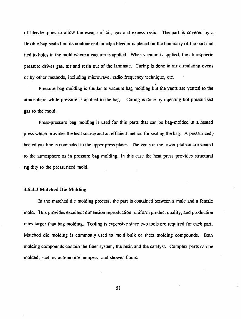
of bleeder plies to allow the escape of air, gas and excess resin. The part is covered by a
flexible bag sealed on its contour and an edge bleeder is placed on the boundary of the part and
tied to holes in the mold where a vacuum is applied. When vacuum is applied, the atmospheric
pressure drives gas, air and resin out of the laminate. Curing is done in air circulating ovens
or by other methods, including microwave, radio frequency technique, etc.
Pressure bag molding is similar to vacuum bag molding but the vents are vented to the
atmosphere while pressure is applied to the bag. Curing is done by injecting hot pressurized
gas to the mold.
Press-pressure bag molding is used for thin parts that can be bag-molded in a heated
press which provides the heat source and an efficient method for sealing the bag. A pressurized;
heated gas line is connected to the upper press plates. The vents in the lower plateau are vented
to the atmosphere as in pressure bag molding. In this case the heat press provides structural
rigidity to the pressurized mold.
3.S.4.3 Matched Die Molding
In the matched die molding process, the part is contained between a male and a female
mold. This provides excellent dimension reproduction, uniform product quality, and production
rates larger than bag molding. Tooling is expensive since two tools are required for each part.
Matched die molding is commonly used to mold bulk or sheet molding compounds. Both
molding compounds contain the fiber system, the resin and the catalyst. Complex parts can be
molded, such as automobile bumpers, and shower floors.
51

3.5.4.4 Filament Winding
In filament winding, continuous fibers are wound over a mandrel. The rovings are placed
on the mandrel by a shuttle that collects the rovings after they are impregnated in a bath of
resin. The speed of the shuttle and the spinning of the mandrel determine the winding angle at
which the fibers are placed. In order to improve fiber placement for mandrels other than
cylinders (ex. the spherical heads of a pressure vessel) more axes are necessary. Computer
controlled machines of up to five axes are available. There are basically two types of machines;
a helical winding machine and a polar winding machine. Polar machines have a very high
production rate, but they are more specialized and less flexible. A wide variety of products of
circular or elliptic shapes are made by filament winding including pipes up to 3.65 m in
diameter.
3.5.4.5 Resin Transfer Molding
A closed, complete mold, with two or more faces of the final part is used in the Resin
Transfer Molding (RTM) process (Fig. 3.5.3). Therefore, virtually unlimited flexibility of part
shapes can be accomplished with RTM. The fibers are placed in the mold, then the mold is
closed, and the resin is injected. As a result, very good fiber placement and high fiber volume
fraction can be obtained with RTM, which results in excellent material properties. The cost of
tooling is high but should not be a concern for high production volumes. The production rate
is low but the process can be highly automated assuring uniformity of the parts which is essential
for structural components. Because of all its advantages, RTM is the process of choice for the
production of complex shapes, like connection details, that are needed for guideway applications.
52

3 . 5 . 4 . 6 P u l t r u s io n
The pultrusion process has one of the highest production rates and the lowest production
cost of all the processing techniques discussed herein. Pultrusion is a continuous manufacturing
process of FRP prismatic sections. In pultrusion, the fibers are pulled continuously through a
resin bath where they are impregnated with the resin (Fig. 3.5.4). The impregnated resins then
go through a steel die with the shape of the final product. The steel die serves to consolidate
the fiber-resin composite and cure the thermoset resin. Cure of the resin is initiated inside
thesteel die by heating the steel die. Cooling may be necessary near the end of the die to
dissipate the heat generated by the resin reaction. A caterpillar pulls the finished composite
continuously at the exit of the die, and a saw cuts the composites to the required length. £
A major modification to the pultrusion process described in this document consists of
replacing the wet bath by injection of resin directly at the die. This modality has many
advantages. Riesins with a short pot-life (the time the resin remains without curing spontaneously)
can be used since only the resin that is needed can be prepared directly at the injection port.
Virtually no volatiles are released to the atmosphere, resulting in improved environmental
conditions at the factory. However, the process can be very expensive and has not been tried
extensively.
The pultrusion process can lead to the production of a variety of structural shapes, with
unidirectional as well as bi-directional fiber orientations. Additional advances (e.g., fiber
connection between back and flange) in mass producing pultruded structural shapes are being
actively considered by the pultrusion industry to improve the strength, stiffness and stability of
these shapes. Epoxies, phenolics and thermoplastics are being used to pultrude structural shapes
in limited quantities.
5 3

TEXTILEPREFORMINFILTRATION
FRONTRESININFILTRATEDREGION
IN F IL T R A T IO N
HEAT PRESSURE
i '1 1 1 1 1 1 i
f t t t I t t t
•VACUUM BAGRESIN INFILTRATED TEXTK.E PREFORMEDGE D A M
C U R E
Fig. 3.5.3 Resin Transfer Molding Process
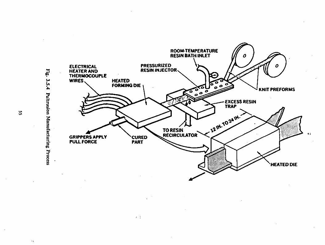
Fig. 3.5.4 Pultrusion Manufacturing Process
ELECTRICALHEATER ANDTHERMOCOUPLEWIRES v HEATED
ROOM-TEMPERATURE RESIN BATH INLET
V
GRIPPERS APPLY PULLFORCE
HEATED DIE

Pultrusion of phenolic resins is difficult because phenolics do not expand before gelation;
therefore, phenolic pultruded materials tend to have a high void content. In addition, phenolics
release water during cure, which tends to be trapped thus forming voids. These shortcomings
are being overcome by new pultrusion arrangements such as the injection at the die and by new
additives formulated specifically for pultrusion of phenolics.
Thermoplastics are difficult to pultrude due to high viscosity. Thermoplastic resin
impregnation is being improved by various methods such as co-mingled fibers, ultrasound and
mechanical impregnators, and ultrasound excited dies that reduce the pulling force significantly.
Currently pultruded sections with a cross sectional area of about 9700 mm2 are commonly
produced. The production rate varies from 300 mm/min to 7500 mm/min, depending on the size
and complexity of the part. The production rate can be increased by running multiple pultrusion
lines simultaneously. The capital investment requirements are low in relation to other
manufacturing processes (e.g., filament winding). A cost comparison among various production
methods used in aerospace applications is shown in Fig. 3.5.5. A cost comparison among
various production methods used for large composite parts is shown in Fig. 3.5.6. From Figure
3.5.6, it can be seen that pultrusion has the lowest cost per part.
In hand lay-up, the operator reads the stacking sequence from the specifications and lays-
up the laminate from tape pre-preg. Pre-plied broadgoods are stacks of pre-preg laminae
(uncured) that already have the stacking sequence desired. Therefore, the production is faster
and cheaper. Pre-plied broadgoods come in rectangular sheets that must be trimmed by hand.
Custom broadgoods come already trimmed, making the production faster and cheaper.
The cost and production time of a typical aerospace part that can be produced by all the
processes listed in Figure 3.5.6 are shown. The cost of the pultruded part was used to
5 6
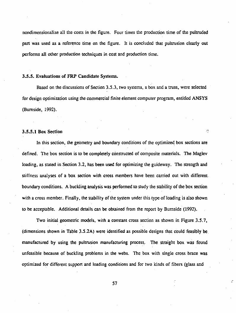
nondimensionalize all the costs in the figure. Four times the production time of the pultruded
part was used as a reference time on the figure. It is concluded that pultrusion clearly out
performs all other production techniques in cost and production time.
3.5.5. Evaluations of FRP Candidate Systems.
Based on the discussions of Section 3.5.3, two systems, a box and a truss, were selected
for design optimization using the commercial finite element computer program, entitled ANSYS
(Burnside, 1992).
3.5.5.1 Box Section ?
In this section, the geometry and boundary conditions of the optimized box sections are
defined. The box section is to be completely constructed of composite materials. The Maglev
loading, as stated in Section 3.2, has been used for optimizing the guideway. The strength and
stiffness analyses of a box section with cross members have been carried out with different
boundary conditions. A buckling analysis was performed to study the stability of the box section
with a cross member. Finally, the stability of the system under this type of loading is also shown
to be acceptable. Additional details can be obtained from the report by Burnside (1992).
Two initial geometric models, with a constant cross section as shown in Figure 3.5.7,
(dimensions shown in Table 3.5.2A) were identified as possible designs that could feasibly be
manufactured by using the pultrusion manufacturing process. The straight box was found
unfeasible because of buckling problems in the webs. The box with single cross brace was
optimized for different support and loading conditions and for two kinds of fibers (glass and
57
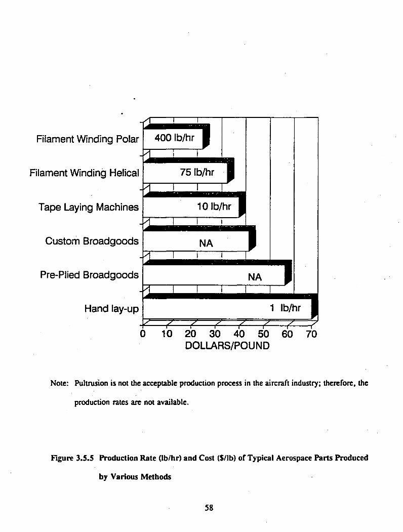
D O L L A R S /P O U N D
Note: Pultrusion is not the acceptable production process in the aircraft industry; therefore, the
production rates are not available.
Figure 3.5.5 Production Rate (lb/hr) and Cost ($/lb) of Typical Aerospace Parts Produced
by Various Methods
5 8
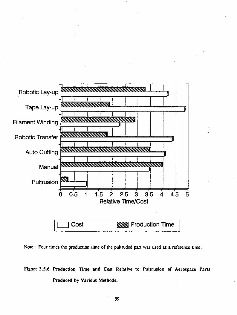
R o b o tic L ay -u p
T a p e L ay -u p
F ila m e n t W in d in g
R o b o tic T ra n s fe r
A u to C u ttin g
M an u a l
P u ltru s io n— i
t
|:
------- 1------- 1------- 1------- 1------- 1------- 1------- 1------- r-----—r------- r0 0.5 1 1.5 2 2.5 3 3.5 4 4.5 5
R ela tiv e T im e /C o s t
I | C o s t P ro d u c tio n T im e
Note: Four times the production time of the pultruded part was used as a reference time.
Figure 3.5.6 Production Time and Cost Relative to Pultrusion of Aerospace Parts
Produced by Various Methods.
59

carbon). The analysis was conducted using two different sets of boundary conditions, simply
supported (SS) and fixed end (CC), as shown in Figure 3.5.8. The jointless (fixed/almost-fixed)
bridge was simulated by constraining the translational and rotational degrees of freedom as
illustrated in Figure 3.5.8.
The structural model has been optimized with reference to volume so that structural
material costs could be minimized. Several design constraints were used in the structural
analysis to control the number of possible solutions. First, the Tsai-Wu failure criteria is the
most accepted criteria for strength evaluation of composites. It is an interactive criteria in the
sense that all stress components (<rx, cy, at, a ^ a^, r„) are used simultaneously to predict failure
against a set of strength values. The mathematical description is given in Tsai (1989) and Jones
(1975).
Tsai-W u=( — +— )o .x c x c 2-A-)o + ( —A+_A) ( j
' y t y c y z c z c ] z
( o x ) 2 ( o y ) 2 < o , ) 2 ( o _ , ) 2 <oy r ) 2 ( o xz ) 2
" r*rc ’ z ' z c * ( ^ V 2+ (*z y*)2 + ( ^ ) 2
C o o^ x y x y C o o
/ W J , \ / W A
C„,o„o C „.o„o,x y x y y* y C o o
f t t W c y/K V cZJc y/Xc*cZcZc
The strength values used in this study are shown in Table 3.5.2. These strength values revealed
that the possibility of first ply failure occurring anywhere in the structure can be prevented.
60

T a b le 3 . 5 .2
Material Properties of the Lamina
Material Property for a Lamina E-Glass/Polyester(GPa)
Carbon/Polyester
Young's Modulus in the Direction of the Fibers 44.730 GPa 132.288 GPa
Young's Modulus Orthogonal to the Direction of the Fibers
7.737 GPa 8.158 GPa
Major Poisson’s Ratio 0.25 0.25
Density of Laminate 2.547 Mg/mJ 2.021 Mg/mJ
Shear Modulus (G 12) 3.0 GPa 3.259 GPa
Ultimate Tensile Stress in the X Direction (Xt) 2.067 GPa 1.137 GPa
Ultimate Compressive Stress in the X Direction (Xc) 2.067 GPa 1.137 GPa
Ultimate Tensile Stress in the Y Direction (Yt)
64.311 MPa 63.808 MPa
Ultimate Compressive Stress in the Y Direction (Yc)
64.311 MPa 63.808 MPa
Ultimate Shear Stress (S) 32.156 MPa 32.156 MPa
61
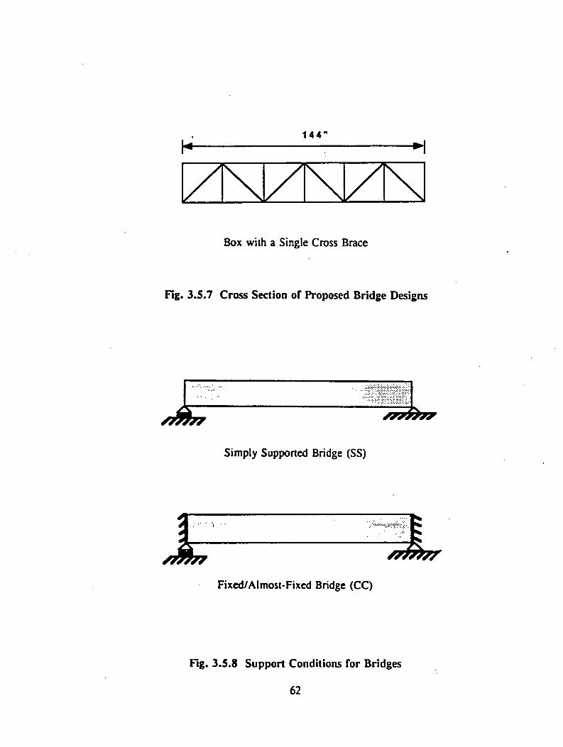
1 4 4 "
Box with a Single Cross Brace
Fig. 3.5.7 Cross Section of Proposed Bridge Designs
^ 7 ^
Simply Supported Bridge (SS)
Fixed/Almost-Fixed Bridge (CC)
Fig. 3.5.8 Support Conditions for Bridges
6 2

Second, the maximum deflection of the structure was not allowed to exceed the allowable limit
of L/2000. Finally, the total thickness of the top, the bottom, and web laminates were
constrained to a maximum thickness of 25.4 mm (1 in) so that pultrusion is feasible. The results
of the optimum process are shown in Table 3.5.2A.
The buckling analysis conducted by Burnside (1992) showed that a simple box section
would not be stable. Therefore, a box section with a cross member was chosen for the
optimization. In this optimization, it was shown that for distributed load of a Maglev system
24.82 kN/m (1700 lb/ft), 20 percent less material was needed to carry the load in the jointless
design over the simply supported system.
Burnside (1992) has shown that a carbon fiber structure must be at least six times smaller
in cross section than the E-glass structure to justify its cost. Although E-glass/polyester
structures required more material, it was still less expensive than a carbon/polyester structure.
A linear buckling analysis was performed by Burnside (1992) to determine the stability
of the structure under Maglev loading conditions. Since the analysis employs an eigenvalue
solution, the results are actually load multipliers for the different buckling failure modes.
Therefore, the results presented in Table 3.5.3 are actual loads that will cause failure. A review
of the results shows that compared to the normal load of 24.82 kN/m (1700 lb/ft), all the
structures could handle more than twice the loading with respect to buckling, with the exception
of SS carbon polyester that showed a 1.276 safety factor. The material properties used in
computing buckling forces are given in Tables 3.5.1 and 3.5.2.
3.S.5.2 Hybrid Truss
In this section, the geometry of the hybrid truss system is discussed, (Fig. 3.5.9), to
illustrate the simplicity of such a structure. Then, three types of support conditions (simply
6 3

T a b le 3 . 5 . 2 A . O p t im iz e d G e o m e t r y o f B o x w it h a S in g l e B r a c e
FIBER
CARBON GLASS
SS CC SS CC
Depth mm 2380 1072 2350 1420(in) (93.7) (42.2) (92.5) (55.9)
T top mm 9.754 18.19 27.18 21.84(in) (0.384) (0.716) (1.070) (0.860)
T bottom mm 17.374 20.88 42.45 26.31(in) (0.684) (0.822) (1.672) (1.036)
T web mm 18.186 29.77 44.91 29.81(in) (0.716) (1172) (1.768) (1.174)
T diag mm 17.424 41.50 33.93 36.02(in) (0.686) (1.634) (1.336) (1.418)
Cross Sect. Area mnr 689031 554940 1487804 738192
(in1)(1021.5) (860.158 (2306.1) (1144.2)
Table 3.5.3 Results of Buckling Analysis Under Maglev Loading
Cross Section Boundary Conditions E-Glass Polyester Carbon Polyester
Box with One Cross
Member per Section
Simply Supported 18,892 N/m 30,044 N/m
Fixed/ Almost-Fixed 35.373 N/m 63,345 N/m
6 4

supported at the bottom of a deck, simply supported at the top of a deck, and fixed/almost fixed-
jointless) are examined. The optimization of the truss members is presented with minimum
stiffness levels. To verify the accuracy of the finite element modeling of the reinforced concrete
deck, strength of materials solutions are developed. Finally, the results of the hybrid truss
system are presented to show that the best solution is one in which vertical and diagonal tubes
are optimized separately.
The loading of a magnetic levitation train on a guideway results in a uniform load that
is about 12.41 kN/m (850 lb/ft), per truss. This load is placed on the top deck directly over
the truss system to get the maximum use of the material. In addition, because the guideway is
fully loaded with uniform load, the maximum deflection effects are studied. The impact loading
is taken into account in the analysis by a factor of 1.8.
Optimization of the Truss System
The model was optimized to minimize the volume of material in the truss members for
a given thickness of the reinforced concrete decks. The wall thickness and the diameters of the
different tubes in the truss system were set as design variables within the program to optimize
the required thickness and diameters of each tube while meeting the various design criteria. The
tubes making up the vertical truss members and also the diagonal members were allowed to vary
independently. The fiber angle of the layers of the laminate was also defined as a design
variable. Several design constraints were used in the structural analysis to determine the
feasibility of possible solutions. First, the maximum value of a two dimensional Tsai-Wu failure
criteria for a representative section of a tube was checked (Bumside, 1992). This prevented the
possibility of first ply failure from occurring anywhere in the structure. Second, the maximum
deflection of the structure was not allowed to exceed the Maglev standard of L/2000 as specified
6 5
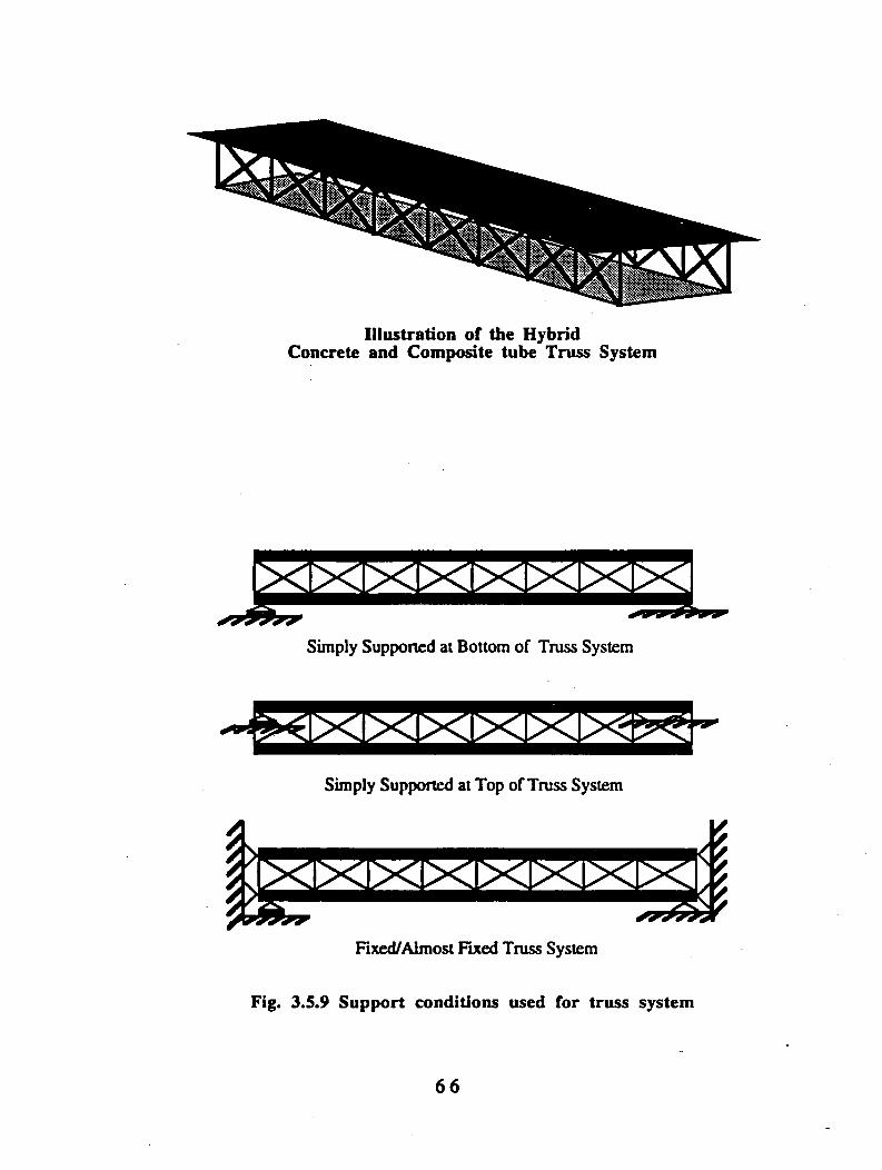
Illustration of the Hybrid Concrete and Composite tube Truss System
4
i : Ix i x i x i x i x i x u x i > ^
Fixed/Almost Fixed Truss System
Fig. 3.5.9 Support conditions used for truss system
66
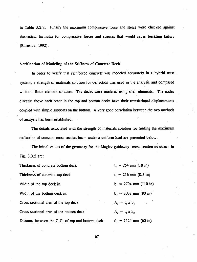
in Table 3.2.2. Finally the maximum compressive force and stress were checked against
theoretical formulas for compressive forces and stresses that would cause buckling failure
(Burnside, 1992).
Verification of Modeling of the Stiffness of Concrete Deck
In order to verify that reinforced concrete was modeled accurately in a hybrid truss
system, a strength of materials solution for deflection was used in the analysis and compared
with the finite element solution. The decks were modeled using shell elements. The nodes
directly above each other in the top and bottom decks have their translational displacements
coupled with simple supports on the bottom. A very good correlation between the two methods
of analysis has been established.
The details associated with the strength of materials solution for finding the maximum
deflection of constant cross section beam under a uniform load are presented below.
The initial values of the geometry for the Maglev guideway cross section as shown in
Fig. 3.3.5 are:
Thickness of concrete bottom deck
Thickness of concrete top deck
Width of the top deck in.
Width of the bottom deck in.
Cross sectional area of the top deck
Cross sectional area of the bottom deck
Distance between the C.G. of top and bottom deck
t2 = 254 mm (10 in)
t, = 2 1 6 mm (8.5 in)
b, = 2794 mm (110 in)
bj = 2032 mm (80 in)
A| = tj x b|
Aj “ tj x bj
d, = 1524 mm (60 in)
6 7

Half the top deck thickness
Span of the guideway system
d2 = 107.95 mm (4.25 in)
L = 24.4 m (960 in)
The following equation for the Z component of the location of the centroid is derived
£geometrically from Figure 3.5.10, where ZTr=d2+dl ( _ —L -)
Al+A2
The Z component of the centriod defines e, and ej from the geometry of the system. The
moment of inertia of the cross section is computed on the basis of the second moment of the area
of the cross section given in Fig. 3.5.10. The maximum displacement for the deck under a
uniform load was then approximated with a strength of materials equation for deflection at the
center of a beam, and the deflection value of 13.513 mm (0.532 in.) for live load is given in
Table 3.4.2. This compared favorably with the finite element model which predicted a
displacement of 13.33 mm (0.52 in) under the same loading; however, one should note that the
above deflection value does not satisfy the vertical deflection limit state and the design needs to
be reviewed.
Results of the Optimization of the Tubes
In this optimization, unlike the box sections, the amount of material needed to carry the
distributed load was significantly affected by the boundary conditions. A 25 percent savings in
material in the jointless design over the simply supported system has been realized for both
E-glass and carbon fibers. This is illustrated for E-glass/polyester in Tables 3.5.4 and 3.5.5.
The carbon/polyester is illustrated in Tables 3.5.6 and 3.5.7. A second optimization on the
68

Fig. 3.5.10 Geometric Representation of Concrete Deck
6 9
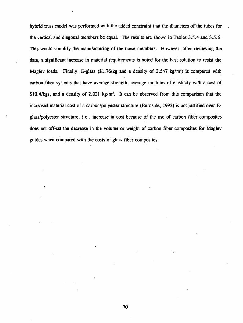
hybrid truss model was performed with the added constraint that the diameters of the tubes for
the vertical and diagonal members be equal. The results are shown in Tables 3.5.4 and 3.5.6.
This would simplify the manufacturing of the these members. However, after reviewing the
data, a significant increase in material requirements is noted for the best solution to resist the
Maglev loads. Finally, E-glass ($1.76/kg and a density of 2.547 kg/m3) is compared with
carbon fiber systems that have average strength, average modulus of elasticity with a cost of
$10.4/kgs, and a density of 2.021 kg/m3. It can be observed from this comparison that the
increased material cost of a carbon/polyester structure (Burnside, 1992) is not justified over E-
glass/polyester structure, i.e., increase in cost because of the use of carbon fiber composites
does not off-set the decrease in the volume or weight of carbon fiber composites for Maglev
guides when compared with the costs of glass fiber composites.
7 0

Table 3.5.4Results or an E-Glass/Polyester Truss System
With the Tube Diameters Equal in All Sections
Boundary Condition Inner Diameter for Both Tubes
mm (in)
Vertical Tubes Diagonal Tubes Volume of Truss System (mm*)
Cost
SFiberAngleDegree-
Wall Thickness mm (in)
FiberAngleDegree
Wall Thickness mm (in)
SS at Bottom 127 24.3 2.95 3.2 6.12 411000(5) (0.17) (0.24)
SS at Top 88 24.8 2.74 1.1 8.56 381000(3.46) (0.11) (0.34)
Fixed/Almost Fixed 117 40.2 2.87 1.4 2.87 203000(4.6) (0.11) (0.11)

T a b le 3 . 5 . 5R e s u l t s o r a n E - G la s s /P o ly e s t e r T r u s s S y s t e m w ith V a r y in g T u b e D ia m e t e r s
BoundaryConditions
Vertical Tubes Diagonal Tubes Volume of Truss System
mm*(in5)
Cost
$Fiber Angle
. Degree
Inner Diameter mm (in)
Wall Thickness mm (in)
FiberAngleDegree
Inner Diameter mm (in)
Wall Thickness mm (in)
SS at Bottom 8.8 32 5.7 2.1 285.8 3 404000(1.26) (0.22) (1125) (0.12) (24.65)
SS at Top 4.3 170 2.7 1.1 185.7 4 161000(6.69) (0.11) (7.31) (0.16) (9.82)
Fixed/Almost Fixed 19.9 30 2.7 1.1 113.8 2.7 98440(11.81) (0.11) (4.48) (0.11) (6.0)
Table 3.5.6Results of a Carbon/Polyester Truss System
With the Tube Diameters Equal in all Sections
Boundary ConditionInner Diameter for Both Tubes
mm (in)
Vertical Tubes Diagonal Tubes Volume of Truss System
mm’(in5)
Cost
$FiberAngleDegree
Wall Thickness mm (in)
FiberAngleDegree
Wall Thickness mm (in)
SS at Bottom 83.8 7.8 10.2 5.7 4.5 315000(3.3) (0.40) (0.18) (19.22)
SS at Top 27.9 26.0 2.7 1.3 8.3 129000(1.1) (0.11) (6.33) (7.87)
Fixed/Almost Fixed 42.7 27.8 4.3 2.5 2.7 123000(1.68) (0.17) (0.11) (7.51)

T a b le 3 . 5 . 7R e s u l t s o r a C a r b o n /P o ly e s t e r T r u s s S y s t e m
Boundarycondition
Vertical Tubes Diagonal Tubes Volume of Truss System mm’ (in3)
Cost
SFiberAngleDegree
InnerDiameter
mm(in)
Wall Thickness mm (in)
FiberAngleDegree
InnerDiameter
mm(in)
Wall Thickness mm (in)
SS at Bottom 23.9 164.8 4.9 2.1 93.7 2.7 244000(6.49) (0.19) (3.69) (0.11) (14.89)
SS at Top 1.3 25.7 2.7 1.1 83.1 2.8 121000(1.0) (0.11) (3.27) (0.11) (7.38)
Fixed/Almost Fixed 4.0 25.7 4.4 2.6 54.9 2.6 83000(1.0) (0.17) (2.16) (0.10) (5.06)
3.6 COMPARATIVE ASSESSMENT OF CONVENTIONAL AND INNOVATIVE
MATERIALS
Sixteen conceptual guideway systems were developed, and seven systems were selected
for further study based on Maglev guideway performance requirements. Simple design guidelines
were used, whenever possible, to evaluate the performance of the selected seven systems. Finite
element analyses were used to design and optimize the trapezoidal concrete box with FRP
reinforcement, hybrid systems with concrete upper and lower decking stiffened by FRP truss
members, and all FRP box systems (Figs. 3.3.2, 3.3.6, and 3.3.7), and conventional analysis
was used to design the remaining four systems. The advantages and disadvantages of the
structural materials used for the design of the most promising systems were evaluated with;
respect to the performance of the systems. To minimize corrosion and electromagnetic effects
from an elevated guideway, the four guideway systems that use composite materials, (Figs.
3.3.2, 3.3.3, 3.3.6, and 3.3.7), should be further evaluated.
3.6.1 Selection of Candidate Systems
The sixteen guideway systems (see Appendix A) are grouped as beam and frame systems,
beam systems stiffened with cables, and truss systems. These systems are further classified in
the following manner for the convenience of technical discussions:
1. Single and continuous span systems
2. Balanced cantilever systems
3. Rigid frame systems
4. Truss systems
7 5

5. Beam systems stiffened with cables
6. Cable supported systems
7. Systems with different cross sectional shapes
8. Systems with different construction materials
1. Single and continuous span systems (Figs. A l, A9, A10, and A12)
Single span guideway systems offer the advantage of ease of design, fabrication,
transportation, erection, and construction over the continuous systems. However, single-span
systems are less efficient in strength and stiffness than continuous systems. Guideways designed
as a two-span continuous system are of lengths 20 percent longer than guideways designed as
simple spans with nearly identical cross sections. Such guideway systems with proper continuitylV
will increase the structural efficiency of a guideway. However, field joining will impose greater
maintenance and serviceability demands.
2. Balanced cantilever systems (Figs. A2 and A4)
Balanced cantilever systems are more efficient and economical than single-span systems
because these systems behave like continuous systems after the placement of field joints at
appropriate locations and the completion of construction of a superstructure. However, the
required field joints at the inflection points of the superstructure do lead to maintenance and
serviceability problems.
3. Rigid frame systems (Figs. A8, A ll , and A13)
The rigid frame systems are more efficient and economical than the single span, balanced
cantilever, and continuous span systems. The rigid frame systems can be designed to half the
7 6
bending moment of simple spans. The rigid frame is four times stiffer than simple single span
system. However, the joint detailing between the sub- and super-structure is complicated,
resulting in a system more susceptible to soil settlements. The rigid frame systems are commonly
referred to as jointless bridges, which are becoming popular in highway construction, but their
long-term performance, due to environmental loads and soil settlement effects, is not well
understood. No specific design and construction specifications are yet available.
4. Truss systems (Figs. A3, A4, A15, and A16)
Truss systems are considered for Maglev guideway applications because they are strong
and stiff in the span direction yet weak in lateral bending and torsion. To improve the lateral
bending and torsional resistance, a truss system needs to be stiffened with deck or slab
components. These components are stiffened also with trusses at certain intervals in the lateral
direction. The fabrication costs are relatively high for truss systems.
5. Beam systems stiffened with cables (Figs. A5, A6, A7 and A14)
Systems in this category deal with superstructural guideways that are stiffened by
providing cables outside of a structure, not inside, i.e. this category does not include pre- or
post-tension operations. Beam systems stiffened with cables increase the strength capacity of
the system, but increase in the stiffness of the system is limited. A maglev guideway system
design is controlled mostly by stiffness criterion, not by strength criterion. Therefore,
strengthening the system with cables is not advantageous. Moreover, the cost of cables,
anchorage systems, and protective devices increases the cost of the structure while being difficult
to maintain.
7 7
Although cable stiffened systems are advantageous for span lengths of more than 152 m
(500 ft.), such long span structures are not suitable for the present Maglev application. These
structures are inefficient under aerodynamic forces.
6. Systems with different cross sections (Figs. A17, and A18)
Closed sections such as trapezoidal, rectangular, and circular are more efficient in
resisting torsional and lateral moments than are open sections. Asymmetric sections about the
strong axis (e.g., trapezoidal section) are more efficient than symmetric box and circular sections
because higher magnitudes of lateral loads can be accommodated (i.e., larger top flange width),
with modest webs and bottom flange widths.
7. Systems with different construction materials (Fig. A17)
Conventional and innovative composite materials were considered for Maglev guideway
systems. The advantages and disadvantages of various construction materials were also studied
(Section 3.5), and emphasis is given to the composite materials with nonmagnetic properties.
Based on these considerations, seven systems were selected for further study, as
described in Section 3.6.2.
3.6.2. Selection of most-promising systems
The following seven guideway systems were selected for further analysis from sixteen
guideway systems (Refer to Appendix A):
1. Trapezoidal concrete box system with steel reinforcement (Fig. 3.3.1)
2. Trapezoidal concrete box system with FRP reinforcement (Fig. 3.3.2)
7 8

3. Rectangular concrete box system with FRP reinforcement (Fig. 3.3.3)
4. All steel trapezoidal box (Fig. 3.3.4)
5. Hybrid system with concrete upper and lower decking stiffened by steel truss
members (Fig. 3.3.5)
6. Hybrid system with concrete upper and lower decking stiffened by FRP truss
members (Fig. 3.3.6)
7. An all FRP box system (Fig. 3.3.7)
These systems are shown in Fig. 3.3.1 through 3.3.7. The design loads for the systems
are discussed in Section 3.2. The overall response of the guideway systems have been checked
for various load combinations. The stresses and deflections are summarized in Tables 3.4.1 and
3.4.2.
3.6.3 Simplified Design of Most Promising Systems
The seven selected systems were designed for the loads specified in Table 3.2.1. The
spans of the systems considered were 24.4 m, all of which were analyzed as simply supported.
The deflection limit for live load is 173600 and for live load plus impact is L/2000. Thus, for
a 24.4 m span, the allowable live load deflection is 6.6 mm and for live load plus impact is
12 mm. The seven systems were evaluated on the basis of deflection for the specified
construction materials. A brief description of the design of these systems is presented.
3.6.3.1. Design of Trapezoidal and Rectangular Concrete and Steel Box Sections
(Figs. 3.3.1 through 3.3.4)
The design of the concrete and steel trapezoidal and rectangular box sections followed
the design guidelines that are well established and available in the literature (AASHTO, 1989,
7 9
ACI, 1989). The design details are given by Wendlik (1992). For example, the concrete
guideway has been examined to evaluate the induced stresses and deformations affecting the
overall design. The governing design aspect of the guideway is the vertical deflection. All
design and performance criteria have been kept at the minimum tolerances to allow the system
to perform satisfactorily. The stringent serviceability limits have been established from ACI,
AASHTO, AREA, and other relevant specifications from the Transrapid designs. The guideway
design substantiates the component behavior in terms of its strength, stability, stiffness,
durability, and fatigue.
3.6.3.2. Design of Hybrid System with Concrete Upper and Lower Decking Stiffened
by Steel or FRP Truss Members (Figs. 3.3.5 and 3.3.6)
The design of the concrete deck with steel or FRP trusses hybrid-system required a finite
element (FE) analysis approach. The hybrid system is described in detail in Section 3.3 and in
the thesis by Burnside (1992). It consists of two concrete decks connected by a truss of steel
or composite tubes. Two versions of the same system were considered, with and without
concrete inside the FRP composite tubes. The concrete filling improves the strength and stiffness
of the FRP tubes and reduces the member and system buckling and natural frequency of
vibration. A special joining detail must be used to join the FRP members to the top and bottom
concrete slabs, as shown in Fig. 3.3.6A. In the design of the hybrid system with concrete filled
FRP tubes the material for the truss members is assumed to be unidirectionally reinforced with
the E-glass fibers aligned with the axis of the member. For the system without concrete inside
the tubes, an optimization formulation was used to efficiently orient the fibers to prevent global
8 0

and local member buckling. Some design details of the FRP truss system are presented by
Burnside (1992).
3.6.3.3. Design of All FRP Box Deck (Fig. 3.3.7)
Based on the conclusions of Section 3.3, prismatic composite sections must be analyzed
in depth for structural members so that they can be produced economically by the pultrusion
process. In order to study the feasibility of using composites for the guideway, an all composite
system was studied. The system is based on a repeated box structure suggested by McGhee
(1990) for bridge decks.
Although there are some simplified methods for the design of composite members
(Sotiropoulos and GangaRao, 1993, Barbero, 1991), they have not been demonstrated for larger
structures. Some of the problems are:
a. Lack of an accurate computation of the shear correction factor.
b. Lack of an accurate computation of bending-extension warping (shear lag).
c. Lateral torsional buckling and local buckling models are just now being developed
(Barbero, 1990, Barbero and Tomblin, 1992, Tomblin, 1992).
Therefore, the analysis was accomplished with a finite element program (Burnside, 1992),
which accounted for the above three factors.
f!
3.6.3.4. Comparisons
The weight of each of the systems is shown in Table 3.4.1. The concrete trapezoidal
section is about three times heavier than the steel trapezoidal section. The system consisting of
concrete decks with trusses weighs about the same when either steel or FRP trusses are used.
81
The maximum stresses for all systems are relatively low (Table 3.4.1), and the maximum live
load deflections are within the specified limits (Table 3.4.2).
All of these systems are simply supported and single module units and, therefore, a span-
by-span erection technique can be used for the trapezoidal systems. The erection of the hybrid
systems can be accomplished by installing the bottom deck, attaching the truss system to the
deck, and placing the top deck over the truss system. The bottom deck can serve as a working
platform to construct the system.
3.6.4 Evaluation of Conventional and Hybrid Materials
Fatigue can be an important factor in the design of guideway systems. The induced
fatigue stress depends on the number of load cycles, the service load stress range, the type of
induced residual stress, and the initial size of a flaw. Steel has good strength and stiffness
properties and higher fatigue strength than concrete or FRP. However, the performance of
Maglev guideway systems based on our designs, does not appear to be controlled by fatigue
considerations, since the stress range is very low (19.77 N/mm2 [2.83 ksi]).
The cost of a guideway system depends on material availability, design and construction
experience on related engineering projects, transportation, and construction methods. The
availability of technical know-how, ease of fabrication and erection, simplicity of details, and
ease of maintenance and repairs are more favorable for steel structures than for concrete and
FRP structures. Fabrication of a steel section is done by means of welding. Efficiency and
accuracy of welding is achieved by using robots. Thus, a simple unit to span 24.4 m (80 ft.)
can be fabricated meeting all functional, design, and tolerance requirements. Modularization
of guideway sections is recommended as will be discussed in Section 3.7.
8 2
Concrete deforms continuously under sustained loads, a phenomenon known as creep.
The volume change due to the change in water content in the concrete is known as shrinkage.
The change in deflections due to creep and shrinkage affect the ride quality. The creep and
shrinkage deflections can be controlled by leaving unstressed prestressing cables in the guideway
which can be stressed in the future to induce upward deflection.
Concrete itself does not exhibit any corrosion problem, but embedded steel reinforcement
in concrete is susceptible to corrosion. Corrosion of steel results in volume increases due to
oxidation. Such volume changes can induce tensile stresses in the concrete. Oxidation also
leads to reduction in the effective cross-sectional area of steel rebars, and loss of strength and
stiffness of the structural system. FRP rebars are non-corrosive, and their application in
structural engineering is gaining importance over conventional steel rebars.
Concrete structures show better dynamic response over conventional steel structures
because of their higher weight. Modularized precast concrete units can decrease costs and
erection time, while providing better quality control. Simple span precast concrete units can be
used to minimize the effects of soil settlements and replacement time. However, the ride quality
suffers as the number of structural joints increases. The structural joints can be reduced by
converting the simple spans into two- or three-span systems, but thermal stresses and deflections
are more critical in continuous structures and must be accounted for in design by providing
expansion joints.
FRP composite materials have several advantages over conventional construction
materials. First, FRP is lighter than steel and concrete, so that the erection and transportation
costs and time for construction are greatly reduced. Modular units fabricated at the shop can
83
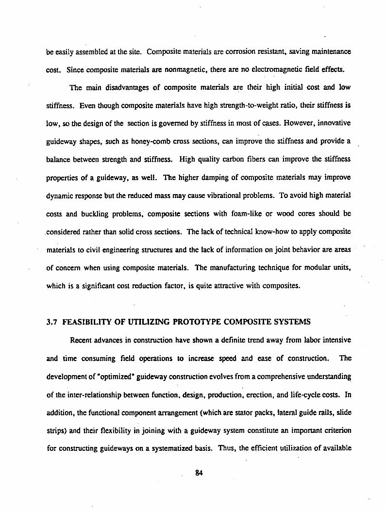
be easily assembled at the site. Composite materials are corrosion resistant, saving maintenance
cost. Since composite materials are nonmagnetic, there are no electromagnetic field effects.
The main disadvantages of composite materials are their high initial cost and low
stiffness. Even though composite materials have high strength-to-weight ratio, their stiffness is
low, so the design of the section is governed by stiffness in most of cases. However, innovative
guideway shapes, such as honey-comb cross sections, can improve the stiffness and provide a
balance between strength and stiffness. High quality carbon fibers can improve the stiffness
properties of a guideway, as well. The higher damping of composite materials may improve
dynamic response but the reduced mass may cause vibrational problems. To avoid high material
costs and buckling problems, composite sections with foam-like or wood cores should be
considered rather than solid cross sections. The lack of technical know-how to apply composite
materials to civil engineering structures and the lack of information on joint behavior are areas
of concern when using composite materials. The manufacturing technique for modular units,
which is a significant cost reduction factor, is quite attractive with composites.
3.7 FEASIBILITY OF UTILIZING PROTOTYPE COMPOSITE SYSTEMS
Recent advances in construction have shown a definite trend away from labor intensive
and time consuming field operations to increase speed and ease of construction. The
development of “optimized" guideway construction evolves from a comprehensive understanding
of the inter-relationship between function, design, production, erection, and life-cycle costs. In
addition, the functional component arrangement (which are stator packs, lateral guide rails, slide
strips) and their flexibility in joining with a guideway system constitute an important criterion
for constructing guideways on a systematized basis. Thus, the efficient utilization of available
8 4

human and material resources could lead to economic, structural, and functional optimization
of a guideway superstructural system. Such an approach is referred to by GangaRao (1978) as
the "Systems Approach" to the construction of guideway systems.
The concept of prefabrication fits in well with the high-volume and mass production of
Maglev guideway superstructural components and their assemblage, leading to system
construction. Owing to the increasing demands for stringent tolerances on guideway structural
and functional components; for reductions in initial, maintenance, and operational costs; and for
energy savings, we are on the threshold of the "prefabrication era" in modem construction
technologies (Sheppard and Phillips, 1989). The beginning of these innovations is apparent in
terms of monorail structures, mass transportation structures and people movers. Three important
trends highlight developments in prefabrication:
1. Standardization of structural shapes and systems for varying span lengths and load
intensities,
2. Mass production of structural components with different materials as steel,
concrete, timber, fiber reinforced composites, or hybrids - a combination of the
above or other materials,
3. Mass transit usage in different modes, including the Maglev mode, requires mass
production of structural components in a prefabrication form for the reasons of
economics, environmental awareness, and energy savings.
Prefabrication technologies have many advantages including mass production of high
quality components which are typically plant-manufactured under ideal quality control conditions,
85

allowing delivery and erection of guideway structures on precise construction schedules. Many
other advantages are listed elsewhere (Merritt and Ambrose, 1990).
In view of the above trends in modem construction techniques, we selected the simply
supported single span guideway structure from the most promising Maglev guideway systems
for detailed design. This structure was designed for strength, serviceability, stiffness, and
stability and the results were reported by Wendlik (1992). Emphasis was placed on production
of guideway system parts and their erection, maintenance, and replacement. Production of
modular units through mass production techniques, connection details for structural integrity,
and other advanced construction techniques were evaluated for the prototype guideway system.
Herein, seven prototype Maglev guideway systems are designed for a span of 24.4 m (80
ft.). The designs were prepared as a part of our research effort and are presented in reports by
Wendlik (1992) and Burnside (1992). The structural components are such that they lend
themselves well to prefabrication and modular construction. The most promising guideway
system is an economical system that meets Maglev functional requirements and is suitable for
mass production. Such systems can be made of different construction materials. Design
constraints such as size, shape, and weight of a module as well as the methods of transportation
and erection of those modules can be accounted for in the design process. In addition, the
selection of material and cross sectional shape(s), simplicity of design and detailing techniques,
construction assemblies, and low self-weight of the modules resulting in easy handling,
transportation, and erection are some of the factors that are evaluated herein for cost reduction
purposes.
86

3.7.1 Identification of Prototype System
The present study has been limited primarily to the guideway superstructural systems with
right-angled supports and simple spans of 24.4 m (80 ft.). The detailed analyses of several
guideway systems were carried out and cross sectional shapes are shown in Figs. 3.3.1 through
3.3.7
The most promising systems (shown in Figs. 3.3.1 to 3.3.7), are designed for the loads
specified in Table 3.2.1. The deflection limits for the live load and live load plus impact are
taken as L/3600 and L/2000, respectively. Thus, for a 24.4 m (80 ft.) span guideway, the
allowable deflection is 7.77 mm (0.2667 in). Different cross sections were evaluated by using
different construction materials with live load deflection limit established as L/3600. The
behavior of hybrid and FRP box sections is not as well established as the behavior of a steel and
concrete guideway structure. In general, the guideway superstructural systems that evolved
through this research are subject to several system constraints. These include size and weight
of the superstructure modules for transportation, crane limits for handling, and erection
techniques. Typically, most superstructural systems in public works outlive their usefulness.
Therefore, a minimum service life of fifty years is considered as another system constraint, and
this constraint has been incorporated in our evaluations.
Before evaluating the guideway systems in-depth, broad issues dealing with module
selection and their transportation and erection are discussed first:
Module Selection: A variety of prefabricated modular shapes must be conceptualized from the
viewpoint of mass production to take full advantage of prefabrication. It should be noted,
however, that these shapes will lead to a conceptual system after the modules are assembled in
8 7
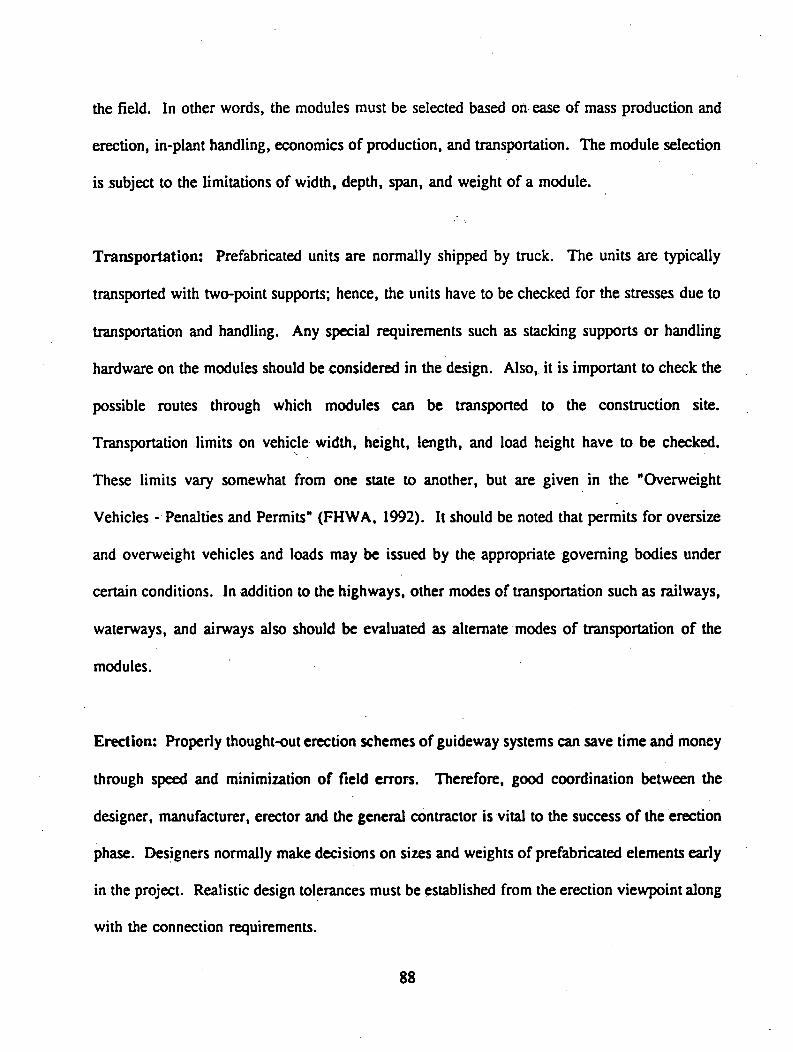
the field. In other words, the modules must be selected based on ease of mass production and
erection, in-plant handling, economics of production, and transportation. The module selection
is subject to the limitations of width, depth, span, and weight of a module.
Transportation: Prefabricated units are normally shipped by truck. The units are typically
transported with two-point supports; hence, the units have to be checked for the stresses due to
transportation and handling. Any special requirements such as stacking supports or handling
hardware on the modules should be considered in the design. Also, it is important to check the
possible routes through which modules can be transported to the construction site.
Transportation limits on vehicle width, height, length, and load height have to be checked.
These limits vary somewhat from one state to another, but are given in the "Overweight
Vehicles - Penalties and Permits" (FHWA, 1992). It should be noted that permits for oversize
and overweight vehicles and loads may be issued by the appropriate governing bodies under
certain conditions. In addition to the highways, other modes of transportation such as railways,
waterways, and airways also should be evaluated as alternate modes of transportation of the
modules.
Erection: Properly thought-out erection schemes of guideway systems can save time and money
through speed and minimization of field errors. Therefore, good coordination between the
designer, manufacturer, erector and the general contractor is vital to the success of the erection
phase. Designers normally make decisions on sizes and weights of prefabricated elements early
in the project. Realistic design tolerances must be established from the erection viewpoint along
with the connection requirements.
88

Although all the guideway systems are technically feasible, they differ in terms of
fabrication, erection, durability, and life-cycle costs. To evaluate the merits and demerits of
these systems, selection criteria based on eight items as given in Table 3.7.1 have been
developed.
For purposes of relative comparison, a weighting technique, as shown in Table 3.7.1,
has been applied. The weighted values for each of the evaluation criteria are based on sound
engineering judgement and previous experience with structural systems similar to the guideways.
It should be noted that the proposed ratings, at best, serve only as guidelines and such
evaluations are based on a degree of subjectivity.
The ratings of the proposed systems involve complex inter-relationship of several
unknowns, such as construction and maintenance costs, performance levels, long-term
degradation rates, and others. Due to the above uncertainties, the rating indices may have to
be lowered to account for these uncertainties. If, on the other hand, the full potential of these
systems is realized, through "hands-on" experiences, the indices of these guideways would be
higher and rating indices can be altered accordingly.
The results of our internal survey of ten technical personnel on evaluation of six Maglev
guideway systems are reported in Table 3.7.1. The steel box system received the highest rating
of 73.6%. This can be attributed to the familiarity of the material and the past usage. However,
the lowest rating (68.6%) was given to the prestressed concrete deck with steel trusses.
Obviously, the spread between the six proposed systems is very narrow for any meaningful
delineation of the best possible guideway system. It is interesting to note that the composite
systems received as good a rating as the well established steel systems. This implies that the
composite guideway systems may be favored more than others, if their long term performance,
8 9
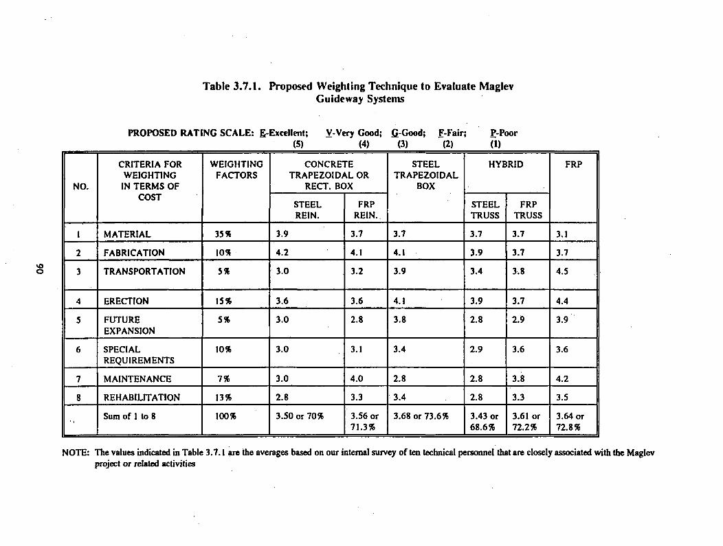
Table 3.7.1. Proposed Weighting Technique to Evaluate MaglevGuideway Systems
PROPOSED RATING SCALE: E-Excellent; V-Very Good; fi-Good; F-Fair; P-Poor(5) (4) (3) (2) (1)
NO.
CRITERIA FOR WEIGHTING IN TERMS OF
COST
WEIGHTINGFACTORS
CONCRETE TRAPEZOIDAL OR
RECT. BOX
STEELTRAPEZOIDAL
BOX
HYBRID FRP
STEELREIN.
FRPREIN.
STEELTRUSS
FRPTRUSS
1 MATERIAL 35 % 3.9 3.7 3.7 3.7 3.7 3.1
2 FABRICATION 10% 4.2 4.1 4.1 3.9 3.7 3.7
3 TRANSPORTATION 5% 3.0 3.2 3.9 3.4 3.8 4.5
4 ERECTION 15% 3.6 3.6 4.1 3.9 3.7 4.4
5 FUTUREEXPANSION
5% 3.0 2.8 3.8 2.8 2.9 3.9
6 SPECIALREQUIREMENTS
10% 3.0 3.1 3.4 2.9 3.6 3.6
7 MAINTENANCE 7% 3.0 4.0 2.8 2.8 3.8 4.2
8 REHABILITATION 13% 2.8 3.3 3.4 2.8 3.3 3.5
■> Sum of 1 to 8 100% 3.50 or 70% 3.56 or 71.3%
3.68 or 73.6% 3.43 or 68.6%
3.61 or 72.2%
3.64 or 72.8%
NOTE: The values indicated in Table 3.7.1 are the averages based on our internal survey of ten technical personnel that are closely associated with the Maglev project or related activities

which can be established through accelerated test procedures, is satisfactorily established and the
guideway system designers are familiar with the design of structures with the FRP materials.
Hence, we recommend that the concrete trapezoidal box system with glass FRP reinforcement,
the hybrid system with prestressed concrete slabs and glass or graphite and composite cellular
decks FRP truss be evaluated further for future construction of Maglev guideways. We
recognize that this recommendation somewhat contradicts the rating values in terms of the FRP
box system. Such a contradictory recommendation is based on the lack of experimental data of
FRP boxes. Our current recommendation on the FRP box will be reevaluated, provided it
performs to our satisfaction under accelerated testing conditions. Faza and GangaRao (1992)
are working on accelerated test procedures to establish master charts for FRP materials so that
aging of these composite materials and, consequently, the life of a structure with FRP can be
predicted with reasonable accuracy.
3.8 SELECTION OF MOST-PROMISING HYBRID SYSTEMS
Based on the rating survey presented in Section 3.7, the following three systems are
recommended for further study: the concrete trapezoidal box system with glass FRP
reinforcement; the hybrid system with prestressed concrete slabs (reinforced with glass FRPs)
and glass or graphite FRP truss system; and the glass or graphite FRP composite cellular deck
with cross bracing (diaphragms).
The reinforcement of concrete with continuous glass FRP tendons has been previously
investigated (Wolff and Miesseler, 1989). A significant number of structures have been built
using this technology. The use of glass or carbon FRP tendons as reinforcing elements in
91

Maglev guideways appears feasible and can be readily implemented. The hybrid system with
concrete decks and glass or graphite FRP trusses offers good damping, strength, and stiffness
characteristics. However, the complexity of the connections and field installation are
disadvantages that must be evaluated in order to establish its competitiveness with the other
proposed systems. Since composites perform differently in tension and compression, the design
must allow for optimization of fiber angle, tube diameter, and tube thickness. For this reason,
previous attempts to design composite truss systems by simply applying steel-design rules have
been unsuccessful. The composite truss system is capable of transmitting the shear forces from
the top to the bottom deck with low shear deformation. An efficient system is the jointless
design (built monolithically with the supports), but in this case, the concrete decks must be
prestressed because of the inducement of tensile stresses.
The cellular glass or graphite FRP box section with cross members can be fabricated by
pultrusion using bidirectional fabrics that can provide continuity between the web and the flange
of the box. Burnside’s stability analysis indicates that the cross members are needed to prevent
buckling of the webs (Burnside, 1992). This cellular system offers several advantages over the
stringer-and-deck systems (Sotiropoulos, GangaRao and Mongi, 1993).
A cellular composite section appears very promising for possible construction as a
Maglev guideway system, but the long-term performance of the system must be established, and
the cost of the structure must be evaluated by including life-cycle considerations.
9 2

3.9 ANALYSIS OF COSTS AND ASSESSMENTS OF ECONOMIC IMPACT OF
MAGLEV GUIDEWAYS
3.9.1 Formulate Framework for Economic Analyses
Background
A review of the literature was conducted and practitioners were consulted relative to
identifying key issues with respect to construction and maintenance of Maglev guideways and
the decision tools and economic analysis techniques appropriate for evaluating these issues. At
least two constraints became clear very quickly. Given the extremely small number of Maglev
guideways which have been constructed and/or proposed around the world, accurate cost data
are difficult to acquire. The task becomes even more difficult for "innovative" guideways. A
second difficulty is that Maglev system research and development is still in a very dynamic state.
As a consequence, the need for and the nature of certain system components have still not been
resolved, e.g., guideway heating systems.
Evaluation Techniques
The following evaluation techniques were felt to be worthy of further consideration:
present worth, benefit-cost ratio, rate-of-rctum, and annual worth approach. Each of these
approaches is described briefly below:
With the net present worth (present value) approach, the stream of costs (and benefits)
is discounted to its present worth (their value now) and then netted to determine the resultant
9 3

net present value. The benefit-cost ratio method, when properly applied, is little different than
the net present worth approach. The only differences are that additional computations are
required and that proper interpretation of the ratios can be confusing in some instances. The
final form of the benefit-cost ratio answer is an abstract number that represents the ratio of net
benefits to net costs.
By definition, the internal rate-of-retum is the interest rate for which discounted benefits
over n years are just equal to discounted costs. The internal rate-of-retum has been popularized
by engineering economists, though it has often been improperly understood, explained, and used.
The characteristic of the method, that of finding a discount rate, is the major objection offered
to its use.%
The annual worth approach is popular because many people, even decision-makers, are
unfamiliar with the other techniques. If all the variations in cash flow can be eliminated and an
investment can be said to result in an equivalent annual cost per year, it is assumed to be more
easily understood.
To select an economic analysis technique for use in this project, five evaluation criteria
were developed. Those criteria were: compatibility with existing models, data requirements,
ease of understanding the method, clarity of results, and computational efficiency.
Using these five criteria, the present worth approach was chosen as the most appropriate
evaluation technique. This technique is both simple and unambiguous in indicating the alternative
with the highest economic potential. None of the other methods are as straightforward; in fact,
some may give ambiguous or incorrect economic indicators as commonly applied (Au, 1983).
The economic analysis also incorporated life cycle costing. Life cycle costing is an
approach to incorporating the total costs (initial, operational, and maintenance) involved over
the lifetime of an asset. The present worth approach can incorporate life cycle costs.
9 4

As mentioned previously, the present worth approach easily allows for comparison of
alternatives using varying values of opportunity costs. The approach requires an identified
analysis period. With the Maglev project, that period is the design life of 50 years.
Uncertainty
The principles of classical economics are based on the assumption of perfect information.
This leads to the belief that all alternative outcomes are known with certainty. However, in real
life, uncertainty is present in almost all decision making activities. Economic analysis is no
exception; because of its future orientation, it is an activity with a high degree of uncertainty
(U.S. Army, 1974). It is generally accepted that within the practical limits of available
resources, an attempt should be made to compensate for uncertainty; this project is no exception.
Uncertainty is frequently distinguished from risk through a delineation between subjective
and objective probabilities. Risk prevails where enough is known to permit assignment of
objectively determined probabilities to all possible outcomes. Uncertainty exists where the
assignment is limited to subjective judgemeht. Objective probabilities for critical variables are
generally not available for this type of systems analysis. Therefore, most studies have addressed
situations containing uncertainty rather than risk.
The reason that uncertainty must be approached directly and analyzed is that the results
may have a direct impact on the choice among alternatives. It is simply not enough to present
a set of alternatives whose costs are based on "most likely" factors and assumptions. The
decision maker needs to be aware of how well the rankings of the alternatives measure up under
reasonable changes to factors and assumptions (U.S. Army, 1974).
95
Four of the traditional approaches to the problem of uncertainty are a fortiori analysis,
contingency analysis, statistical uncertainty and sensitivity analysis (U.S. Army, 1974). A
fortiori analysis involves deliberate attempts to formulate assumptions that tend to uniformly
favor or disfavor a particular alternative. A contingency analysis is designed to identify
significant uncertainties of a qualitative nature; it does not attempt to indicate the effect on study
results. The statistical approach results in a number of regression-related statistics and
associated tests to measure how good an estimator the regressions are on an overall basis.
Sensitivity analysis considers factor values under various assumptions in order to determine the
range of impact that changes in quantitative data will have on the costs of each alternative.
Because an uncertainty analysis can be very time-consuming, one of the more
straightforward approaches was undertaken for this project. A sensitivity analysis was used to
address the quantitative aspects of uncertainty that are associated directly with the Maglev system
parameters. Sensitivity analysis was performed by formulating a variety of value estimates for
the selected sensitivity variables.
3.9.2 Development of Construction Cost Data
Capital cost estimates are key ingredients in determining the cost effectiveness, financial
capacity, and overall engineering feasibility of major capital investments, such as Maglev
(UMTA, 1981). Sound methods and reliable cost information are particularly important when
comparing cost effectiveness and financial impacts among alternative systems. This is especially
critical with respect to a Maglev guideway system. Construction of the Maglev guideway has
been estimated to account for as much as 80 percent of all capital costs involved with overall
system construction (Phelan, 1990).
96

Capital Cost Elements
The construction and installation costs associated with the guideway element are functions
of many factors, both design-specific and site-specific. In this report, unless otherwise defined,
the term guideway will refer to the guideway structural components only. The capital costs
developed for this evaluation included only those elements that comprise the guideway structural
system. No costs associated with the magnetic or electrical components on the guideway are
taken into consideration. The actual type of levitation (attraction or repulsion) and guidance
system are concept specific and the cost of the magnetic and electrical components of any
particular system is assumed to be equal across alternative guideway systems.
Innovative Systems
Capital cost data for a variety of structural configurations and subsystems and
construction processes were developed. In many cases, suppliers of materials or services were
contacted to provide reliable cost estimates. For those situations where there are no reliable
existing data, standard cost estimating procedures and sourcebooks were employed (for example,
Means Construction Cost guides). An extensive literature review in this area was completed.
However, because of the scarcity of existing Maglev systems, very little historical data on
Maglev guideway capital costs exist. Discussions with practitioners in the Maglev field resulted
in a similar conclusion. With respect to the more traditional mass transit guideways, extensive
capital cost information was obtained. As noted earlier in this report, seven guideway designs
were identified for evaluation and development. Cost estimates were prepared for five of these.
These include a concrete trapezoidal box section with steel rebar, the same concrete box section
9 7
with FRP rebar, a steel trapezoidal box section, a hybrid concrete-FRP truss system and a steel
truss (these are described in more detail elsewhere in the report). Note that cost estimates were
not prepared for the two designs involving only FRP materials. The lack of existing data on
materials and labor costs precluded the development of reliable cost estimates.
One of the more challenging problems in the estimation of capital costs arises from the
fact that the innovative guideway designs being proposed in this project do not currently exist.
Estimating labor costs involved in construction proved to be difficult. There is no actual data
relative to the quantities of labor required for construction and installation, especially with the
FRP truss system. Discussions were held with FRP manufacturers to help determine labor times
for these systems. The labor costs for the trapezoidal concrete box section with FRP rebar were
easier to determine since this system closely resembles a standard steel rebar box section.
Another issue relative to labor cost estimation is that of production/installation costs. The
question of whether the guideways will be mass produced or if a new construction technique will
be used significantly affects the costs. Economic analysis of different construction techniques
was beyond the scope of this study. The costs presented in the economic analysis section are
not meant to be used as actual construction costs; they should be used only for the purpose of
comparing alternative guideway designs and providing a general estimate of the costs.
Construction Cost Estimates
Concrete trapezoidal box with steel reinforcement: The concrete trapezoidal box
system for the proposed Maglev guideway is by far the most used section. The trapezoidal box
section has been used in highway design for many years. As a result, the estimation of costs
for this "common" system proved to be the most straightforward.
98

Because of the weight of the guideway, off-site modularization of a 24.4 meter (80 ft.)
beam would not be feasible. As a result, the construction plan includes on-site construction of
the beams. It is envisioned that a construction area directly adjacent to the permanent location
of the beams will be utilized. As progress on the Maglev line continues, the construction area
will move along the route. The capital costs developed for the trapezoidal box (Table 3.9.1) do
not include advanced preparation of the construction area. It is anticipated that this area will be
developed when construction of the guideway’s footings and supports is undertaken.
After consultation with manufacturers of Concrete structures, it was determined that steel
forms would be used in the construction process. The initial stage includes the placing of
concrete for the bottom and the two sides of the box. The second stage includes the placing of
the top slab. In the second stage, steel-framed wood forms will be used in the interior of the
box. These lighter forms will make removal much easier than if steel forms were lodged in the
box’s interior.
The detailed cost analysis for the single guideway concrete trapezoidal box with steel
reinforcement is presented in Eck and Hyre (1992b). A summary of. the major cost elements
is presented in Table 3.9.1. Unless otherwise noted, all of the prices, man-hours, etc. used in
this analysis were obtained from Mean's 1992 pricing catalogs. All material quantities were
provided by other team members.
Concrete trapezoidal box with FRP reinforcement: The only difference between this
box system and the first box system discussed is the reinforcing material. This guideway was
99

Table 3 .9 .1 . Cost Elements of Concrete Trapezoidal Box with Steel Reinforcement
SUMMARY OF CAPITAL COSTS HIGH LOWM aterial C osts
Form work $ 5 4 ,1 2 5 $ 4 1 ,1 2 5
Concrete $ 1 3 1 ,3 5 5 $ 1 3 1 ,3 5 5
R einforcing Steel $ 1 3 ,1 4 4 $ 1 3 ,3 1 3
Stressing Tendons $ 1 2 2 ,4 3 0 $ 6 9 ,9 6 0
Labor Costs
Formwork $ 2 8 7 ,2 2 4 $ 2 8 7 ,2 2 4
Concrete $ 9 5 ,2 4 6 $ 9 5 ,2 4 6
R einforcing $ 1 3 ,0 4 4 $ 1 3 ,0 4 4
T ensioning $ 5 3 ,8 7 3 $ 4 1 ,9 9 3
Installation $ 2 0 0 ,1 2 5 $ 2 0 0 ,1 2 5
T O T A L (per km) $ 9 7 0 ,5 6 6 $ 8 9 3 ,3 8 5
T O T A L A verage $ 9 3 1 ,9 7 6
plus 10% for contingencies = $ 1 ,0 2 5 ,2 0 0 /km
100

designed to take advantage of the electromagnetic advantages of FRP. In terms of construction
costs, the reinforcing material cost and reinforcing-associated labor costs are the only
differences. The material costs increase, while the labor costs decrease. The reduction in labor
costs is due to the elimination of a crane from the work crew. The light weight FRP can be
easily handled without the use of a crane. A summary of capital costs for material and labor
is given in Table 3.9.2.
Steel trapezoidal box: While keeping the same trapezoidal shape as the previous two
guideways, the steel box section will require a major variation in construction. None of the steel
manufacturers contacted by the project team had ever dealt with such a large flat steel structure.
As a result, the construction technique proposed may not be entirely accurate. The technique
outlined will, however, be adequate for cost estimating purposes, and the capital costs summary
is given in Table 3.9.3.
It was assumed that each 24.4 meter (80 ft.) side, top, and bottom element can be
shipped intact to the site. Since the costs of the steel are based on smaller quantities, the savings
from large quantities will be offset by the higher transportation costs. Once at the site, cranes
will be utilized to hold the plates in place until welded together. Steel supports will be used to
support the structure until the entire beam has been welded together.
Steel truss system: The construction of this guideway system is not extremely
complicated. The bottom concrete deck would be placed first with the steel studs protruding
from the finished grade. The top deck would be constructed upside down at the same time. The
next step is the placement of the steel truss members on the bottom slab. The final step is the
placement of the top slab onto the steel truss system. The capital cost summary is given in
Table 3.9.4.
101
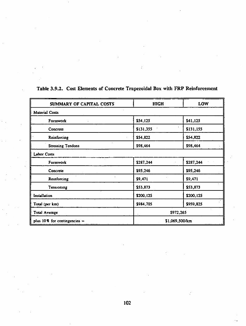
Table 3 .9 .2 . Cost Elements of Concrete Trapezoidal Box with FRP Reinforcement
S U M M A R Y O F C A P IT A L C O S T S H IG H L O W
M aterial C osts
Form work $ 5 4 ,1 2 5 $ 4 1 ,1 2 5
Concrete $ 1 3 1 ,3 5 5 $ 1 3 1 ,1 5 5
R einforcing $ 5 4 ,8 2 2 $ 5 4 ,8 2 2
Stressing Tendons $ 9 8 ,4 6 4 $ 9 8 ,4 6 4
Labor C osts
Form work $ 2 8 7 ,2 4 4 $ 2 8 7 ,2 4 4
Concrete $ 9 5 ,2 4 6 $ 9 5 ,2 4 6
R einforcing $9 ,471 $ 9 ,4 7 1
T ensioning $ 5 3 ,8 7 3 $ 5 3 ,8 7 3
Installation $ 2 0 0 ,1 2 5 $ 2 0 0 ,1 2 5
Total (per km) $ 9 8 4 ,7 0 5 $ 9 5 9 ,8 2 5
Total Average $ 9 7 2 ,2 6 5
plus 10% for contingencies = $ l ,0 6 9 ,5 0 0 /k m
102
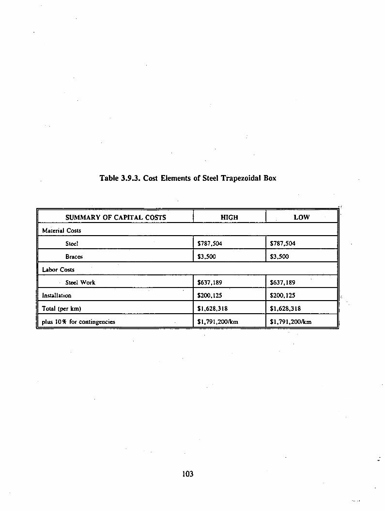
Table 3 .9.3. Cost Elements of Steel Trapezoidal Box
S U M M A R Y O F C A P IT A L C O ST S H IG H L O W
Material C osts
Steel $787 ,5 0 4 $ 7 8 7 ,5 0 4
Braces $ 3 ,5 0 0 $ 3 ,5 0 0
Labor C osts
Steel W ork $637 ,1 8 9 $ 6 3 7 ,1 8 9
Installation $200 ,125 $ 2 0 0 ,1 2 5
Total (per km) $ 1 ,6 2 8 ,3 1 8 $ 1 ,6 2 8 ,3 1 8
plus 10% for contingencies $ l,7 9 1 ,2 0 0 /k m $ l,7 9 1 ,2 0 0 /k m
103
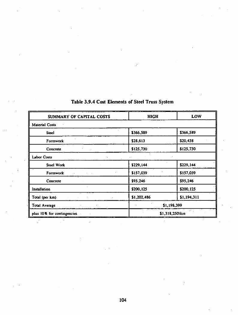
Table 3.9.4 Cost Elements of Steel Truss System
SUMMARY OF CAPITAL COSTS HIGH LOWM aterial C osts
Steel S 366 .S 89 $ 3 6 6 ,5 8 9
Form work $ 2 8 ,6 1 3 $ 2 0 ,4 3 8
Concrete $ 1 2 5 ,7 3 0 $ 1 2 5 ,7 3 0
Labor C osts
Steel W ork $ 2 2 9 ,1 4 4 $ 2 2 9 ,1 4 4
Formwork $ 1 5 7 ,0 3 9 $ 1 5 7 ,0 3 9
Concrete $ 9 5 ,2 4 6 $ 9 5 ,2 4 6
Installation $ 2 0 0 ,1 2 5 $ 2 0 0 ,1 2 5
Total (per km) $ 1 ,2 0 2 ,4 8 6 $ 1 ,1 9 4 ,3 1 1
Total Average $ 1 ,1 9 8 ,3 9 9
plus 10% for contingencies $ l ,3 1 8 ,2 5 0 \k m
104
FRP truss system: The construction of this system is as unconventional as its design.
The FRP truss system is filled with concrete at the same time the bottom deck is placed. This
arrangement provides for continuity in the concrete. The bottom deck will be entirely enclosed
with a steel form. The FRP truss system will then be erected on top of the steel form. The
actual members will be fitted through openings in the form while the entire FRP structure is
supported by wood braces. Concrete will be pumped into the steel form and into the FRP
members. Quality control will be particularly important, but at this time no other method of
construction is available. Once this system is in place, the top concrete slab will be placed, and
the cost elements of FRP Truss system are shown in Table 3.9.5.
3.9.3 Development of Maintenance Cost Data
If estimating the capital costs of a Maglev guideway is a challenging task, estimating
maintenance costs is even more difficult. Not only is there no history of experience to draw
upon but, in some cases, the detailed configuration of system components has. not yet been>re-
determined.
A potential wealth of maintenance data is available from conventional transit systems.
The types of data available have been identified and evaluated for their appropriateness to the
Maglev situation. Of particular interest is how the approaches used by other investigators can
be verified with data from conventional systems.
Maintenance Cost Elements
Many elements need to be considered when discussing the maintenance cost of a
guideway. The type and number of elements vary from guideway to guideway. Regardless of
105
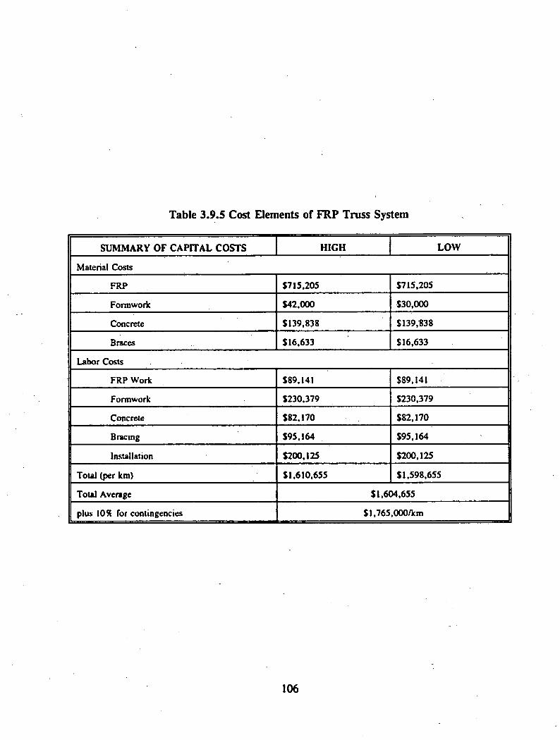
Table 3.9.5 Cost Elements of FRP Truss System
S U M M A R Y O F C A P IT A L C O S T S H IG H L O W
Material Costs
FRP $ 7 1 5 ,2 0 5 $ 7 1 5 ,2 0 5
Formwork $ 4 2 ,0 0 0 $ 3 0 ,0 0 0
Concrete $ 1 3 9 ,8 3 8 $ 1 3 9 ,8 3 8
Braces $ 1 6 ,6 3 3 $ 1 6 ,6 3 3
Labor Costs
FRP W ork $89 ,141 $89 ,141
Formwork $ 2 3 0 ,3 7 9 $ 2 3 0 ,3 7 9
Concrete $ 8 2 ,1 7 0 $ 8 2 ,1 7 0
Bracing $ 9 5 ,1 6 4 $ 9 5 ,1 6 4
Installation $ 2 0 0 ,1 2 5 $ 2 0 0 ,1 2 5
Total (per km) $ 1 ,6 1 0 ,6 5 5 $ 1 ,5 9 8 ,6 5 5
Total Average $ 1 ,6 0 4 ,6 5 5
plus 1091 for contingencies $ l,7 6 5 ,0 0 0 /k m
106

the type, the largest element in guideway maintenance typically is the labor cost. The other
guideway maintenance cost element is materials cost.
During normal operations, guideway maintenance consists principally of inspections and
scheduled preventive maintenance tasks and repair of components or subsystems which have
failed. As noted by Bechtel (1990), guideway maintenance should be scheduled, whenever
possible, to be performed by the late-night shift or to coincide with low passenger demand
periods to provide maximum system availability during peak demand. The overall goal should
be to maintain the guideway structure (piers, beams, etc.) in a safe and reliable operating
condition for maximum system performance.
Preventive maintenance programs (e.g., inspection and cleaning) for guideways should!
be based on calendar time and controlled by life cycle data. Bechtel (1990) has proposed
preventive maintenance frequencies for different aspects of the guideway structure; these are
shown in Table 3.9.6. The differences between the different types of inspections were not
described in the report.
Corrective maintenance involves two aspects. Failures which affect passenger service
and which require immediate attention in order to restore normal operations will be performed
immediately. Defects or failures which do not immediately affect passenger service should be
corrected as quickly as possible to prevent future interruption of operations.
There are two basic approaches to estimation of maintenance costs for Maglev guideway
systems. The first determines labor costs on the basis of a maintenance activity plan for each
guideway component. The activity plan should permit evaluation of labor hours/costs by type
of repair and item, frequency of repairs per item, and material costs per item. The materials
107
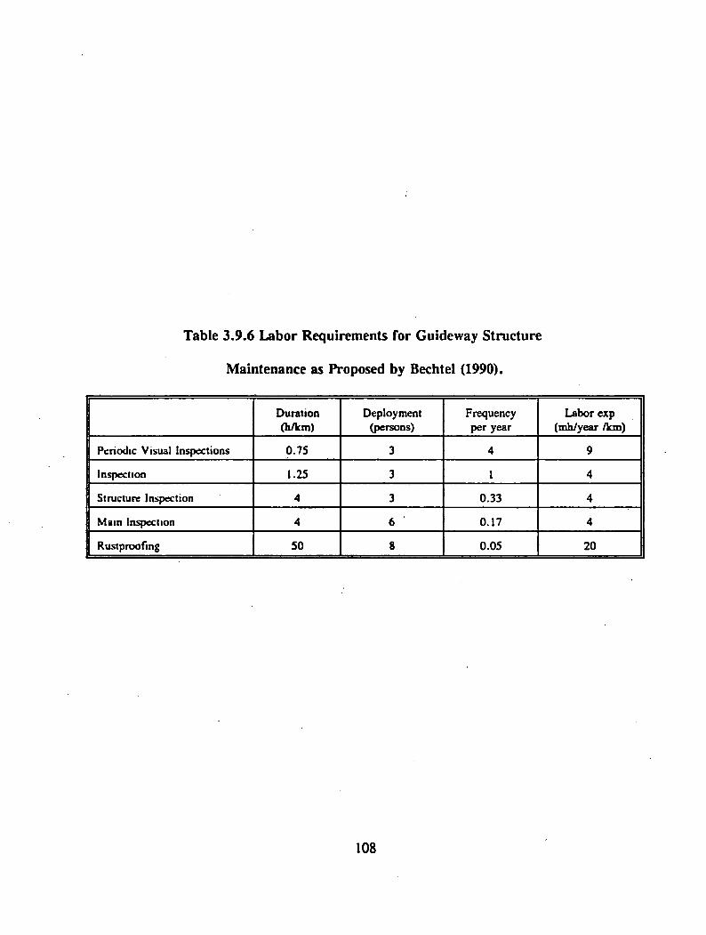
Table 3.9.6 Labor Requirements for Guideway Structure
Maintenance as Proposed by Bechtel (1990).
Duration(h/km )
D eploym ent(persons)
Frequency per year
Labor exp (m h/year /km )
Periodic Visual Inspections 0 7 5 3 4 9
Inspection 1 .25 3 1 4
Structure Inspection 4 3 0 .3 3 4
Main Inspection 4 6 0 .1 7 4
Rustproofing 50 8 0 .0 5 2 0
108

costs are then determined as a function of the capital costs. The calculation of material costs
is based on capital costs, service life, and share of substitute material. For guideway
structuremaintenance, Bechtel (1990) has estimated a service life of 80 years and a maintenance
material cost of one percent of capital costs.
The second approach, in addition to using a function of capital costs for the material
costs, also expands this function to include labor costs. This procedure applies an annual
percentage maintenance factor against the initial capital cost of each element to arrive at a gross
annual maintenance cost for that element which includes both material and labor. This
procedure is used by Transrapid and is based on the methodology specified under Germany’s
"Federal Traffic Act” for use in project evaluations for the German National Railways. The*
Transrapid percentage labor/materials disaggregation is 0.08 percent. In a review and revision
of capital and operating costs for the Las Vegas-Southern California Maglev corridor, the
Canadian Institute of Guided Ground Transport (1986) revised the percentage upward to 0.12
percent for guideway maintenance. This was done because of site specific conditions - the more
demanding seismic and climatic conditions in the Southern California corridor.
The problem with all Maglev guideway maintenance estimates is the lack of a historical
record. Even data from the Transrapid system demonstration line in Germany (not available for
this project) would not provide a total validation due to its relatively brief existence, Because
of the large initial capital costs, a small change in the maintenance factor percentage creates a
significant change in the maintenance cost estimates. For example, the CIGGT change from
0.08 percent to 0.12 percent for the Southern California corridor increases the annual guideway
maintenance costs by 50 percent.
109

Applicability of Conventional Transit System Data
Because of the lack of detailed cost data for Maglev guideways, and consequently the
ability to validate the percentages being used, the modification and application of conventional
guideway transit system maintenance costs to Maglev appears to be an approach which deserves
close examination. The merits of this approach include the ability to validate the rule-of-thumb
percentage approach and the identification of guideway components that may contribute to high
maintenance costs.
One such conventional transit system, the Morgantown, West Virginia, Downtown People
Mover (DPM), has a wealth of detailed and long-term maintenance data. Thus, this project used
conventional transit system maintenance data to help estimate the maintenance costs for proposed
Maglev guideway systems.
The Morgantown DPM involves small rubber-tired vehicles (8 seated passengers, 20
standing passengers) operating over a concrete guideway. The system operates in either an on-
demand mode or a fixed schedule (short headways) mode, 16 hours per day, 6 days per week.
The original system (approximately 8 km [S miles] in length) was opened to passengers in 1975.
A second phase, which increased the system length to about 12.8 km (8 miles), was completed
around 1980.
The process of gathering the guideway maintenance data from the Morgantown DPM
required considerable time. Since the focus of this effort was on only the guideway, it was
necessary to manually examine a printout highlighting the entire system maintenance records and
select only those maintenance items judged to be pertinent to the Maglev guideway situation.
Next, each individual maintenance record had to be located and examined. In a typical year,
110

almost five thousand maintenance records are created. From the individual maintenance records,
items of interest were reviewed to determine date, location, task, type of materials used and
man-hours of labor involved. An item of major interest not on the individual records is the
quantity of material used for each repair. Normally; this information , can be found from a
second database. However, due to the nature of repairs made to the guideway, this information
generally was not recorded in the second database. The type of information stored in the
second database was concerned more with vehicle maintenance, such as quantity of computer
chips changed or tires replaced, as opposed to the guideway maintenance items, such as number
of bags of cement used. Typically, a maintenance worker would only use a portion of a bag of
cement or bucket of concrete patching material. These materials would be taken from storage
and when the amount of cement would run low, more would be purchased. Therefore, the
material costs had to be obtained from purchase orders. Although overall material costs per year
were determined, it is impossible to break down the amount of material used for each individual
maintenance job.
The guideway maintenance costs associated with the Morgantown DPM are relatively
low. In the system’s twenty-year history, deterioration of the guideway structure has been
minimal. At this juncture* it is important to recognize the inherent differences between
acceptable tolerances with a Maglev system and a DPM transit system. One major element of
concern in certain Maglev systems is the differential elevations of connecting spans at their
joints. Due to the strict tolerances in some Maglev systems, the alignment of this joint is
critical. In the DPM system, the alignment is critical only with respect to ride comfort.
Therefore, maintenance costs of this joint will be higher with the Maglev system than with the
DPM system.
I l l

In addition to those elements mentioned previously, another area of guideway
maintenance concern, developed from examination of the DPM system, includes the use and
maintenance of embedded sensors or communications loops in the guideway and how that will
affect the guideway surface. Other minor maintenance issues include debris falling on the
guideway and vandalism.
Data from the Morgantown DPM have been compiled for calendar years 1989 and 1991
and summarized in Table 3.9.7. Because of the significant amount of time required in obtaining
the data and difficulties in compiling the information, only these two years could be used for this
project. However, based on discussions with DPM officials, it is fair to say that the amount of
maintenance activity for 1990 is similar to that of 1991 and likewise that 1988 is similar to 1989.
Based on preliminary investigations, maintenance activity for the two years preceding 1988 was
slightly less than the 1991 activity. Note that the maintenance costs are shown with and without
the heating system (i.e. embedded pipes in guideway.)
The 1989 data demonstrate the influence of system rehabilitation on maintenance costs.
As can be seen from Table 3.9.7, the guideway maintenance cost (excluding guideway heating
elements) for 1991 was just over $10,950 or $850 per kilometer ($1,360 per mile). For 1989,
the guideway maintenance cost was $20,450 or almost double that of 1991. The difference in
annual guideway maintenance costs for the two years is due to major rehabilitation of pier pads
during 1989 (and 1988 as well). The rehabilitation of pier pads is labor intensive work done at
heights (on scaffolding) in tight spaces; thus, the high costs for the procedures.
As a function of the original capital costs, the 1991 maintenance percentage was 0.02
percent without the heating system and 0.03 percent including the heating system. For 1989,
112

Table 3.9.7. Summary of Morgantown DPM Cost History.
System Length = 12.9 kilometers (8.1 miles)
Total Capital Costs (1992) : 5268,000,000
Guideway Capital Costs (1992) : $ 63,100,000
Annual Guideway Maintenance Costs
Item
1991 1989
Total Cost Per Km Costs T otal C osts Per Km C osts
Excluding Heating System SI 0 .9 5 0 $850 $ 2 0 ,4 5 0 S I .5 8 0
W ith Heating SystemSI 9 .2 5 0 S I .490 $ 2 0 ,5 9 0 S I ,595
Maintenance Costs As Percent of Capital Costs
Item 1991 1989
Excluding Heating System 0 .0 2 St 0.03%
With Heating System 0.03% 0.03%
113
the percentage was 0.03 percent for both scenarios. Although these percentages are very low,
they are closer to the Transrapid (Las Vegas to Los Angeles) maintenance cost percentage
estimates than those proposed by CIGGT and Bechtel. The effects of maintenance of guideway
joints for Maglev systems would cause an increase in the percentage. One conclusion from the
Morgantown data (and examination of the Transrapid (Las Vegas to Los Angeles) and CIGGT
data) is that the Bechtel estimates appear to be extremely high.
The Morgantown DPM system was built in two phases. The first phase, which is
approximately twenty years old, consists of concrete piers, steel beams, and a concrete running
surface. The second phase, which is just over twelve years old, consists of concrete piers,
concrete beams, and a concrete running surface. From examination of the maintenance data,
it can be concluded that approximately ninety percent of all maintenance activity has focused on
the first phase guideway. The concrete in the second phase is in excellent condition and shows
no sign of wear. One advantage which the second phase had is that any design "flaws" found
in the first phase were corrected in the construction of the second phase.
Overall, for the Morgantown system, maintenance activity system-wide appears to be
stabilizing. Preliminary analysis of 1990 data and data up to May, 1992, support this
conclusion. As a result, it is concluded that after twenty years of operation, a guideway’s annual
maintenance cost as a percentage of capital costs will become stable. This is shown conceptually
in Figure 3.9.1. The only change would come from any rehabilitation done on the system.
However, it is extremely difficult to predict accurately at what times in a particular guideway’s
life major rehabilitation will be required. This depends on the actual design and construction.
A "rtaw" requiring major rehabilitation, may arise after a few years of operation or the
guideway may complete its estimated life with little or no rehabilitation required.
114

IITime
Figure 3.9.1. Guideway Maintenance Costs as a Percentage of Capital Costs Maintenance Cost Estimates
In terms of Maglev, the project team is confident that the 0.08 percent figure for the
Transrapid system is more realistic than others proposed. However, the initial annual
maintenance costs will likely not be this high. It is proposed that the annual maintenance cost
of the guideway will initially be close to zero but will gradually increase, as time passes, to the
0.08 percent level as indicated for Transrapid. Once reaching this level, the annual costs will
remain constant (neglecting inflationary increases). It is important to note that this analysis deals
only with the guideway structure itself. These annual maintenance cost figures do not include
any of the other features of a Maglev system (e.g., guideway heating, footings, etc.).
An important question is what will be the difference in annual maintenance costs for the
five guideway systems identified in the preceding section. That is, is there a difference in how
each system approaches the 0.08 percent annual level, or is it possible that the non-conventional
guideways may not even reach the 0.08 percent level or may, in fact, exceed that level? The
Transrapid value of 0.08 percent was based on a concrete trapezoidal guideway. It was assumed
that the two concrete trapezoidal guideways (one with steel reinforcement the other with FRP)
will reach the 0.08 percent level. The analysis for the other systems, however, is not as
115
straightforward. Since the steel trapezoidal guideway will not involve any concrete maintenance,
there should not be the high maintenance costs associated with concrete. The last two systems -
the steel truss and FRP truss - involve concrete, but not as extensively as the two trapezoidal
guideways. While intuitively it would appear that the FRP truss system would require slightly
less maintenance than the steel truss system, the unique design of concrete-filled FRP trusses
complicates this issue. The authors are not certain about the long term performance of FRP
materials even though preliminary results indicate much better FRP performance than concrete
or steel. As a result, it is felt that these two systems will have similar maintenance cost
requirements. However, since the future annual maintenance is based only on engineering
judgement, the economic analysis includes life-cycle costs with various maximum maintenance
percentages for the guideways ranging from 0.08 to 0.12 percent. As a reference when
examining the maintenance costs in the economic analysis section, the total estimated annual
guideway maintenance costs for the 370 kilometer (231 miles) Los Angeles to Las Vegas Maglev
system is $888,000. (CIGGT, 1986)
3.9.4 Economic Analyses
The purpose of the economic analysis is to examine how the life-cycle costs of the five
guideway systems under consideration vary with respect to changing variables. Not only is it
possible to compare the guideways with each other, it is also possible to determine the sensitivity
of the guideways to specific maintenance costs and interest rates. The results provide decision
makers with the information necessary for the selection of a course of action.
116

It should be noted that the maintenance costs obtained from the economic analysis are
based on "bare" capital costs. Contractor overhead and profits plus engineering fees are not
included. As a result, the annual maintenance costs appear to be low.
Project Scenarios
This section presents a sample calculation for the economic analysis of a steel trapezoidal
box system. Calculations for the costs of the other systems presented were performed in an
identical fashion.
Capital cost = $179,125/km (111,955/miles)
At 8% interest rate-
R .12a te .
.04
0 20 50
Year
This run will have the annual maintenance costs beginning at .04% and reaching 0.12% at year
20. After that, the annual maintenance costs will remain at 0.12% of the initial capital costs for
the life of the system.
117

At 0 .04% annual costs, maintenance costs = $720/km
0.06% =$1,075
0.08% =$1,440
0.10% =$1,795
0.12% =$2,150
Capital Costs:
0 50
$179,125
"Increasing" Maintenance Costs (years 0-20):
0 20
118

Stable" Maintenance Costs (years 21-80):
20 21 49 50
$2 50 $2150
Note: Money for annual maintenance costs needs to be available
starting January 1 of the year in question, thus maintenance money
for year 1 must be available at time 0. and money required for year
80 must be available at time 79.
NPW = $179,125 + $78.75 + $78.75(P/A,8,20) + $71.56(P/G,8,20)
+ ($2150(P/A,8,59)(P/F.8,20)]
Using standard engineering economics tables.
-NPW = $179,125 + $718.75(9.8181) + $71.56(69.0898)
+ $2150(11.1584)(.2145) - $1,809,116/km
The remaining runs were calculated using the same procedure. The results are shown in Tables
3.9.8 through 3.9.12.
119

Annual Maintenance Cost Percentage Scenario Conceptual Graph
Rate
Conventional Versus Innovative Designs
The life-cycle costs, as implemented, were found to have very little influence on the cost
differential among the alternatives. Three distinct ranges of costs of the five guideway systems
were evident. The concrete trapezoidal boxes (both steel reinforced and FRP reinforced)
represent the low end, the steel truss system represents mid-range, and the steel trapezoidal box
and FRP truss system represent the high end of costs. One interesting finding from the data is
that the steel truss system appears to be more cost effective than the steel trapezoidal box system
(Tables 3.9.8 and 3,9.9). The large quantity of steel required for the trapezoidal box is the
cause of the higher cost.
As expected, the more traditional trapezoidal concrete box guideways appear to be best
in terms of cost effectiveness (Tables 3.9.11). It should be noted, however, that factors other
than cost play a role in the final selection process. The issue of electromagnetic interference
from steel could eliminate the three steel guideways from further consideration.
The analysis examined only two interest rates, 8 and 10 percent. Initially, many more
rates were planned to be examined. However, after two iterations, it became apparent that as
120
the interest rate increased, the difference in costs at the various maintenance percentages was
less important. In other words, the higher the interest rate, the less influence maintenance costs
have on the total costs. Conversely, lower interest rate levels and changes in the anticipated
annual maintenance costs can have a major effect on the total cost.
Role of Diagnostics
As discussed elsewhere in this report, guideway diagnostics and monitoring are very
important aspects of the operation and maintenance of a Maglev guideway. In terms of costs,
the use of these nondestructive testing and monitoring methods will certainly increase
construction costs. While the costs are considerable, such systems have the potential to save
money in terms of the ability to detect problems early, thus avoiding major repair costs.
However, a great deal of study needs to be done in this area before meaningful cost
estimates can be made and economic analyses performed. Two items are especially important
from an economic standpoint. First, the sensors to be used need to be determined. Several
possible sensors are outlined in the next chapter. It is not likely (nor feasible) that all of these
techniques would be utilized on a particular Maglev system. However, the optimum
combination needs to be determined. Secondly, once the system(s) to be used has been
identified, the details of the monitoring system must be specified so that realistic cost estimates
can be prepared. Only when such data are available can the life cycle cost consequences of
guideway diagnostics and monitoring be assessed.
121

Table 3.9.8 Net Present Worths for Steel Trapezoidal Box
Maintenance Rate Interest RateA B s% 10%
.04% .12% SI. 809.116 $1,805,048
.04% .10% SI.807,033 $1,803,564
.04% .08% $1,804,950 $1,802,081
.04% .06% $1,802,830 $1,800,573
.06% .12% $1,811,740 $1,807,449
.06% .10% $1,809,656 $1,805,967
.06% .08% $1,807,553 $1,804,484
.08% .12% $1,814,409 $1,809,894
.08% .10% $1,812,326 $1,808,412
.08% .08% $1,810,242 $1,806,928
.10% .10% $1,814,948 $1,810,813
.12% .12% $1,819,655 $1,814,698
122

Table 3 .9 .9 . Net Present Worths for Steel Truss System:
Maintenance Rate Interest Rate
A B 8% 10%
.04% .12% $ 1 ,3 3 1 ,1 1 5 $ 1 ,3 2 8 ,2 0 0
.04% .10% $ 1 ,3 2 9 ,6 0 4 $ 1 ,3 2 7 ,1 3 4
.04% .08% $ 1 ,3 2 8 ,0 9 4 $ 1 ,3 2 6 ,0 4 9
.04% .06% $ 1 ,3 2 6 ,3 0 6 $ 1 ,3 2 4 ,9 6 6
.06% .12% $1,333 ,071 $ 1 ,3 3 0 ,0 1 0
.06% .10% $ 1 ,3 3 1 ,5 5 9 $ 1 ,3 2 8 ,9 2 6
.06% .08% $ 1 ,3 3 0 ,0 4 9 $ 1 ,3 2 7 ,8 4 1
.08% .12% $ 1 ,3 3 5 ,0 0 4 $ 1 ,3 3 1 ,7 8 0
.08% .10% $ 1 ,3 3 3 ,4 9 3 $ 1 ,3 3 0 ,6 9 4
.08% .08% $ 1 ,3 3 1 ,9 8 2 $ 1 ,3 2 9 ,0 8 2
.10% 10% $ 1 ,3 3 5 ,4 2 5 $ 1 ,3 3 2 ,4 6 5
.12% .12% $ 1 ,3 3 8 ,8 6 9 $ 1 ,3 3 5 ,3 2 0
123
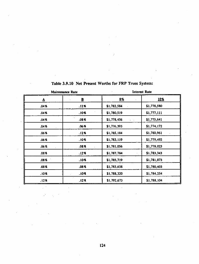
Table 3.9.10 Net Present Worths for FRP Truss System:
Maintenance Rate Interest Rate
A 1 8% 10%
.04% .12% S I .7 8 2 ,5 8 4 $ 1 ,7 7 8 ,5 8 0
.04% .10% S I .7 8 0 ,5 1 9 $ 1 ,7 7 7 ,1 1 1
.04% .08% $ 1 ,7 7 8 ,4 5 6 $ 1 ,7 7 5 ,6 4 1
.04% .06% S I .7 7 6 ,3 9 3 $ 1 ,7 7 4 ,1 7 2
.06% .12% $ 1 ,7 8 5 ,1 8 4 $ 1 ,7 8 0 ,9 6 1
.06% .10% $ 1 .7 8 3 .1 1 9 $ 1 ,7 7 9 ,4 9 2
.06% .08% S I .7 8 1 .0 5 6 $ 1 ,7 7 8 ,0 2 3
.08% .12% S I .7 8 7 .7 8 4 $ 1 ,7 8 3 ,3 4 3
.08% .10% S l.7 8 5 ,7 1 9 $ 1 ,7 8 1 ,8 7 3
.08% .08% S I .7 8 3 .6 3 8 $ 1 ,7 8 0 ,4 0 3
.10% .10% $ 1 ,7 8 8 ,3 2 0 $ 1 ,7 8 4 ,2 5 4
.12% .12% SI .7 9 2 .6 7 3 $ 1 ,7 8 8 ,1 0 4
124
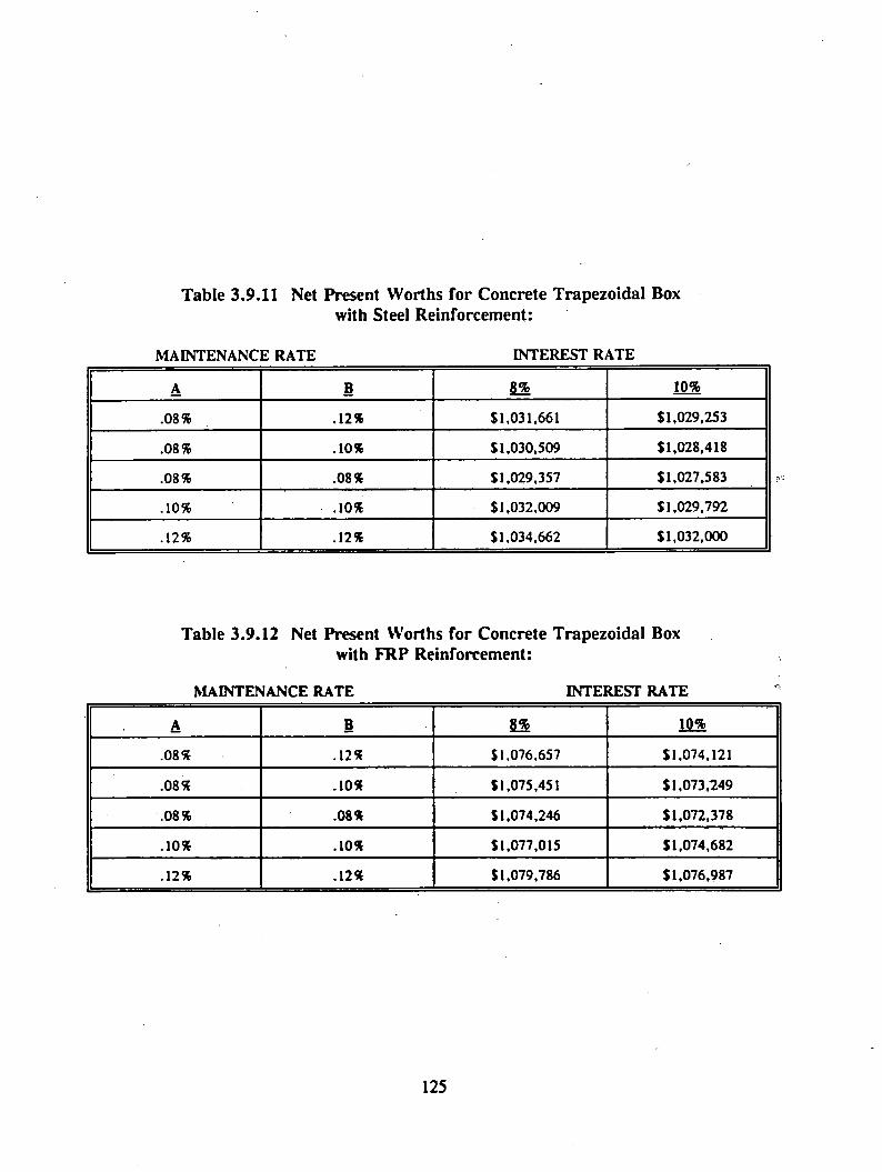
Table 3.9.11 Net Present Worths for Concrete Trapezoidal Box with Steel Reinforcement:
MAINTENANCE RATE INTEREST RATE
A B 8% 10%
.08% .12% $1,031,661 $1,029,253
.08% .10% $1,030,509 $1,028,418
.08% .08% $1,029,357 $1,027,583
.10% .10% $1,032,009 $1,029,792
.12% .12% $1,034,662 $1,032,000
Table 3.9.12 Net Present Worths for Concrete Trapezoidal Box with FRP Reinforcement:
MAINTENANCE RATE INTEREST RATE
A B g% 10%
.08% .12% $1,076,657 $1,074,121
.08% .10% $1,075,451 $1,073,249
.08% .08% $1,074,246 $1,072,378
.10% .10% $1,077,015 $1,074,682
.12% .12% $1,079,786 $1,076,987
125

3.10 DEVELOPMENT OF TEST PLAN
3.10.1 Test Plan Preparation
A test plan is proposed herein with a view to aid the future development in the areas of:
(1) Maglev guideway design,
(2) uses of various construction materials for structural components,
(3) fabrication/manufacturing processes, and
(4) nondestructive evaluation techniques (NDT)
In order to investigate the parameters affecting Maglev guideways and to assess the safety
and reliability of the guideway systems, the test plan is proposed in terms of laboratory testing,
field experiment, and field demonstration phases (see Figure 3.10.1)
3.10.1.1 Laboratory Phase
Prior to field exposure, testing under controlled conditions is required. Therefore, the
laboratory testing phase should include the following:
1. Building and testing of several structural components in the laboratory to determine
static, thermal, dynamic, and fatigue responses.
A. Structural response studies of thermal, creep and shrinkage of the material, and
study of the fatigue response of various components and numerical evaluations
using numerical techniques.
126

F i g . 3 . 1 0 . 1 T h r e e P h a s e s o f t h e P r o p o s e d T e s t P l a n
127

B. Evaluation of methods for rehabilitation of damaged main components and
replacement of secondary components with reference to the structural
performance of a Maglev system.
C. Detailed cost analysis of elevated guideway systems and development of economic
models for various manufacturing/fabrication processes of guideways.
II. Building of experimental structural components with embedded sensors (such as
ultrasonic, acoustic emission, and fiber optic sensors) which can be used for
nondestructive monitoring.
A. Evaluation of various NDT sensor techniques for their accuracy and reliability,
sensitivity, ease of data acquisition, and quality control of the curing process
(monitoring strength increase with curing time) under controlled conditions of the
laboratory,
B. Evaluation of NDT methods using embedded fiber optic cables and
microbending/deforming teeth.
C. Design and detailed cost analysis of the operational system for nondestructive
monitoring, which includes a remote data acquisition system using cellular phone,
state-of-the-art data analysis, and interpretation concepts.
III. Construction of a Magnetic Influence Laboratory to study the effect of magnetic field on
various components and the magnetic field influence on various appurtenances.
A. Establishment of magnetic drag forces as a function of area, cover and type (open
vs. closed loop) of steel reinforcement.
B. Study of the effect of magnetic fields on various sensors which will be used to
monitor guideway systems.
128
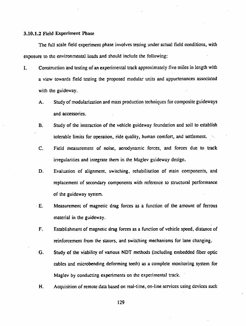
3.10.1.2 Field Experiment Phase
The full scale field experiment phase involves testing under actual field conditions, with
exposure to the environmental loads and should include the following:
I. Construction and testing of an experimental track approximately five miles in length with
a view towards field testing the proposed modular units and appurtenances associated
with the guideway.
A. Study of modularization and mass production techniques for composite guideways
and accessories.
B. Study of the interaction of the vehicle guideway foundation and soil to establish
tolerable limits for operation, ride quality, human comfort, and settlement.
C. Field measurement of noise, aerodynamic forces, and forces due to track
irregularities and integrate them in the Maglev guideway design.
D. Evaluation of alignment, switching, rehabilitation of main components, and
replacement of secondary components with reference to structural performance
of the guideway system.
E. Measurement of magnetic drag forces as a function of the amount of ferrous
material in the guideway.
F. Establishment of magnetic drag forces as a function of vehicle speed, distance of
reinforcement from the stators, and switching mechanisms for lane changing.
G. Study of the viability of various NDT methods (including embedded fiber optic
cables and microbending deforming teeth) as a complete monitoring system for
Maglev by conducting experiments on the experimental track.
H. Acquisition of remote data based on real-time, on-line services using devices such
129

as cellular phones. Analyses and interpretation of the data collected from NDT
sensors embedded in the guideway using information management systems
(computer science fields).
I. Feasibility studies to prove the assumptions in the economic models regarding the
manufacturing/fabrication processes.
3.10.1.3 Field Demonstration Phase
After extensive testing of the Maglev components in the laboratory and the whole system
in the field, a prototype (e.g., 20 mile long test track) will have to be built as a demonstration
system with limited access to passengers and exposure to actual field conditions to evaluate
performance.
3.10.2 Diagnostics and Monitoring Techniques for Maglev Guideways
3.10.2.1 Introduction
The state-of-the-art in nondestructive testing (NDT) technology has advanced significantly
over the past fifteen years and has reached a stage where continuous monitoring of structures
can be successfully achieved. The adoption of advanced NDT technology for Maglev is
absolutely essential because of the Maglev system safety considerations and high cost of
guideway construction. Therefore, several monitoring methods have been evaluated (Sections
3.10.2.2 to 3.10.2.7) in terms of their possible use in a Maglev system.
130

3.10.2.1.1 General Monitoring Concept
The general monitoring concept for the Maglev system has two major objectives:
* Early detection of damage to the guideway system.
* Prevention of catastrophic structural failures.
These objectives can further be integrated into two different stages of the life of a
guideway:
* During construction.
* Post-construction period.
Monitoring methods can either be real-time (i.e., continuous with embedded sensors) or
periodic (i.e., intermittent surveying).
The essential steps in the monitoring process are:
1. Identification of defects or damage.
2. Determination of suitable methods to predict distress.
3. Determination of steps to minimize, prevent, or eliminate impending distresses.
3.10.2.1.2 Guideway Defect and Damage Identification
During construction, the monitoring requirements are as follows:
* Curing of the construction material (e.g., maturity and heat of hydration
measurements in concrete);
* Time-dependent strength variation (e.g., ultimate growth of concrete strength with
time);
* Geometric alignment, with tolerance needs defined; and
131
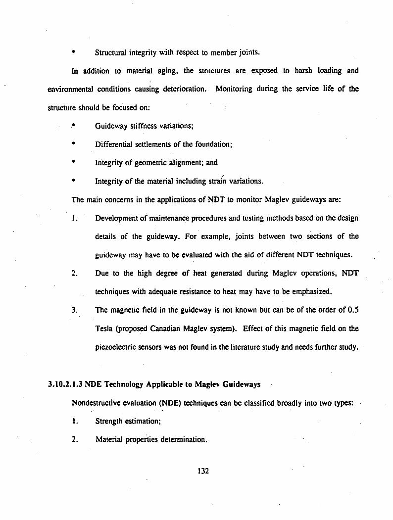
* Structural integrity with respect to member joints.
In addition to material aging, the structures are exposed to harsh loading and
environmental conditions causing deterioration. Monitoring during the service life of the
structure should be focused on:
* Guideway stiffness variations;
* Differential settlements of the foundation;
* Integrity of geometric alignment; and
* Integrity of the material including strain variations.
The main concerns in the applications of NDT to monitor Maglev guideways are:
1. Development of maintenance procedures and testing methods based on the design
details of the guideway. For example, joints between two sections of the
guideway may have to be evaluated with the aid of different NDT techniques.
2. Due to the high degree of heat generated during Maglev operations, NDT
techniques with adequate resistance to heat may have to be emphasized.
3. The magnetic field in the guideway is not known but can be of the order of 0.5
Tesla (proposed Canadian Maglev system). Effect of this magnetic field on the
piezoelectric sensors was not found in the literature study and needs further study.
3.10.2.1.3 NDE Technology Applicable to Maglev Guideways
Nondestructive evaluation (NDE) techniques can be classified broadly into two types:
1. Strength estimation;
2. Material properties determination.
132

Strength estimating techniques are more traditional and include the surface hardness
methods (such as test pistols, rebound hammers, etc.), the penetration resistance methods (e.g.,
Windsor probe, pin penetrator, etc.), the pullout test and the break-off test methods. These
methods are very slow and cause minor localized damages in the structure. Hence, they are not
suitable for monitoring Maglev systems.
Material property determining techniques, on the other hand, cause no significant
disturbances in the structure, can be easily automated, and used as long-term monitoring
methods. Some of the property determining methods are acoustic emissions, laser alignment,
ultrasonic, ground penetrating radar, thermograph, fiber optics, and others. These methods are
more fully elaborated in the following sections.
3.10.2.2 Acoustic Emission
Acoustic emissions (AE) can be defined as the stress wave released by a material that
undergoes irreversible changes. AE sensors detect audible or sub-audible stress waves to find
the deteriorating conditions of a structure. For example, acoustic emissions due to the release
of internal energy from the cracks in construction materials or from debonding in the case of
reinforced concrete, can be picked up by piezoelectric transducers.
Parameters most commonly used in AE analysis include the number of events, the peak
amplitudes, the rise times, the event duration, and the ringdown counts. Common analyses
conducted in AE include: energy or slope determination, amplitude distribution, frequency
analysis, and location determination. AE sensors, amplifiers, data acquisition system and post
processor required to conduct an AE test is identified in Fig. 3.10.2.
133

AE Diagnostic Set-Up
Fig. 3.10.2 Acoustic Emission Set-up Technique
134

Currently at WVU, studies have been conducted involving crack propagation, yield
strength determination, ultimate strength prediction and plastic zone locations ahead of the crack-
tip in concrete material. Delamination, fiber fractures, and damage location studies on FRP
composites are being conducted and the results evaluated.
Acoustic Emission Monitoring System
Figure 3.10.3 shows a proposed design of an AE system applied to the Maglev guideway.
The AE sensors can be embedded in the structure at the critical locations and can perform
continuous monitoring. However, due to the high cost of the sensors, it is advisable to apply
metal waveguides to conduct the waves to the sensors. The waveguides are integrated into the
structure, particularly over the locations where damages are most critical, and are linked to
embedded AE sensors. Hence, a good waveguide would be one that can transmit the signal the
farthest and involve the least attenuation.
Research is currently underway at WVU to study the behavior of waveguides. One of.
the suggestions for reinforced concrete structures is that the reinforcement within the concrete
structure can be used as waveguides. Waveguides will not, on the other hand, be necessary for
a steel structure.
3.10.2.3 Geometric Alignment Using Laser
Track geometric variations can provide information on the movement and damage of
guideway sections. On a macro-scale, issues such as differential settlements, ground heavings,
and horizontal land movements will all result in guideway geometric alignment deviation. On
a micro-scale, interior cracks or expansions of a guideway section may result in surface
135
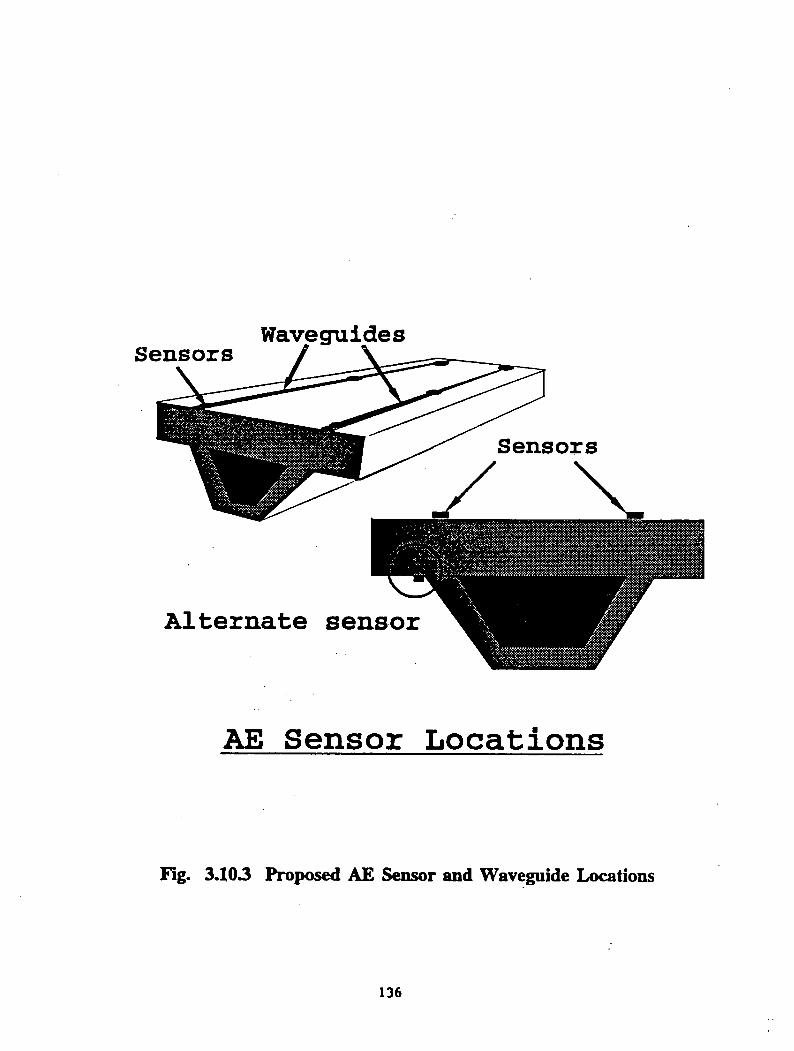
W avegu id esS e n so r s
A l t e r n a t e s e n s o r
A E S e n s o r L o c a t i o n s
Fig. 3.103 Proposed AE Sensor and Waveguide Locations
136

irregularities. These deformations can sometimes be identified by visual inspection. More
accurate methods involve the application of a high-tech laser tracking method.
Defined as the emission of molecular and ionized beams, laser can be useful for
monitoring the alignment of structural geometry. The system consists of a laser light source,
reflectors, receiver, and a date acquisition system. It involves the emission and reception of
molecular/ionized particle beams with the reflected wave pattern giving out useful information.
Compared to conventional surveying techniques, laser has its advantages in high precision data
measurements and in the ease of its application.
The laser guideway application can be distinguished as either a local system (mounted
on a test car), or a global system (placed at a fixed station). The global system may be directly
placed on the guideway or at a certain distance away from the guideway.
The test car technique is currently available and has been applied for the purpose of
monitoring the alignment of railway systems (CSX Report, 1990). In this application, a test car
is equipped with a laser emitting apparatus along with an electronic video camera for receiving
the reflected beam. The reflector is placed permanently on the track (railway). A proposed
setup for Maglev systems is shown in Figure 3.10.4. The test car is allowed to travel at a
designated speed, typically about 80 kmph (SO mph). Similar test cars can be designed for
Maglev applications (Figure 3-10.5). Another alternative is to install the laser source and
camera directly onto the Maglev vehicle.
Figure 3.10.4 shows a Maglev test car similar to the CSX test car with two reflectors
fixed along the guideway. By receiving the reflected laser beam by two high-speed cameras, ,
137
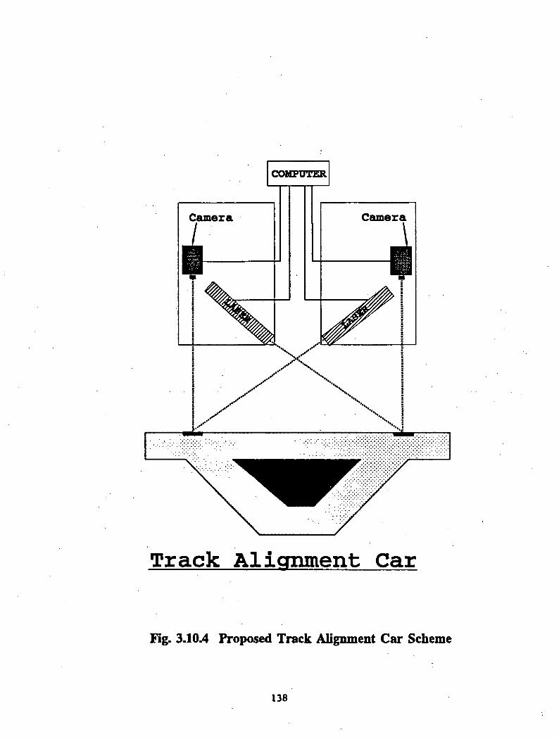
COMPUTER
T r a c k A l i g n m e n t C a r
Fig. 3.10.4 Proposed Track Alignment C ar Scheme
138
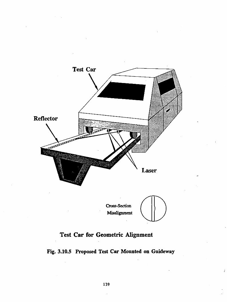
Test Car
Cross-SectionMisalignment
Test Car for Geometric Alignment
Fig. 3.10.5 Proposed Test Car Mounted on Guideway
139

the deformation of the cross section can be determined. This method is more efficient than the
other proposed methods but is limited to detection of cross sectional misalignment.
Figure 3.10.6 shows the global laser system for geometric alignment. The laser source
and the reflectors are fixed on some extensions on the guideway. By reflecting the light source
over the surface of the guideway, adequate information regarding track geometry can be
retrieved, information which can be used to detect both longitudinal (along track length) and
cross-sectional misalignment. This system may also be used for the detection of debris on the
track. Fixed laser systems that can be placed underneath a guideway have certain advantages,
such as no need to be set up every time.
3.10.2.4 Ultrasonics
The ultrasonic pulse velocity method is a good NDE technique for the condition
assessment of concrete. In this method, an electronic pulse is generated and then transformed
into complex mechanical waves (usually a combination of compression, shear, and surface
waves), that are propagated through the specimen. The travel time and the wave velocity can
be measured to determine the material properties of the concrete. Ultrasonic velocities are
sensitive to material constituents, density, elastic modulus, moisture content, and internal cracks
and voids.
This method has good reliability and accuracy in the case of steel structures, but the
heterogeneity of concrete might pose some problems in the analysis. Research conducted at
WVU and elsewhere (e.g., Limaye and Krauss, 1991) has shown that this technique is capable
of detecting cracks and delaminations in concrete. However, ultrasonic sensors need to be in
140

Longitudinal Cross-SectionMisalignment Deformation
Laser on External Wall and Zig - Zag above the the Guideway Surface
Fig. 3.10.6 Proposed Fixed Laser-Reflector Geometric Alignment System

contact with the test specimen (wet coupled or dry coupled), and may require the sensors to be
fixed or embedded.
Ultrasonic transducers can be affected by the magnetic field caused by passing trains.
This effect is temporary, and the interference will fade as the train moves away. In such a case,
the output from the sensors will have to be ignored during the time the train is passing over the
specific region. Magnetic fields can also cause permanent damage to the piezoelectric sensors
in ultrasonic transducers. However, the effect of these magnetic fields on the ultrasonic sensors
is not yet known. Additional research needs to be undertaken to determine these effects.
In the case of a steel guideway system, different types of distresses can occur over a
period of time (e.g., cracks, corrosion). Ultrasonics can be used for detection of cracks up to
3 mm minimum thickness, and determination of their extent and orientation. Corrosion can be
detected by determining the thickness of steel members using focussed ultrasonic transducers
(Singh and McClintock, 1983). However, detection of incipient corrosion and evaluation of
corrosion rates by ultrasonics is difficult.
Ultrasonic Monitoring System
The main components of the ultrasonic monitoring system are shown in Fig. 3.10.7.
Significant advances have been made in the area of signal processing of ultrasonic data whereby
analysis of the output in the frequency domain has led to improved results (Limaye and Krauss,
1991).
The various guideways designed for Maglev systems were thoroughly studied for possible
distress locations. The levitation magnets are located below the overhang portion of the
guideway and support the entire weight of the Maglev vehicle. This creates tension on the top
142
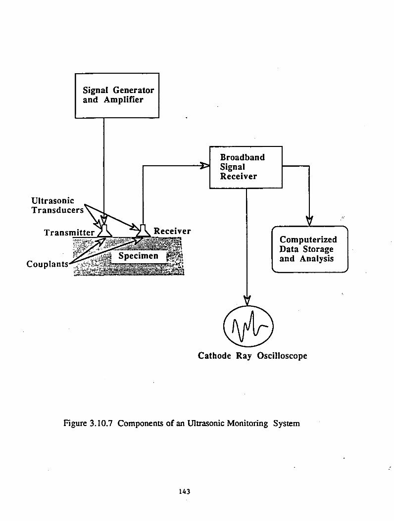
Figure 3.10.7 Components of an Ultrasonic Monitoring System
143
surface of the guideway near the support of the overhang portion of the guideway, causing the
information of vertical cracks along that line. Vertical cracks are best detected by surface
transducers, and two sensors are required for each location. With six possible locations (as
shown in Fig. 3.10.8), 12 sensors are required for each section.
In addition, positive bending moment at the midspan of the guideway section leads to
tension development at the bottom part of the box section. It is estimated that two surface
transducers (not shown in Fig. 3.10.8) will be sufficient to detect any vertical cracks at the
midspan, requiring a total of 14 sensors per section. Assuming an average span for each section
to be around 24.4 m (80 ft.), there are approximately 40 sections per km (65 sections per mile)
or 560 sensors per km (910 hundred sensors per mile). For the data acquisition and processing
system, a single computerized data acquisition system can handle about 14 sensors, i.e., one
system per section will be required. These systems are manufactured by several firms.
3.10.2.5 Ground Penetrating Radar (GPR)
The Ground Penetrating Radar (GPR) technique can be used effectively for condition
assessment of concrete structures. This is a non-contact technique and has the advantages of fast
and easy data acquisition. The GPR, which utilizes short pulse electromagnetic waves, has a
common antenna for both transmitting and receiving the radar signals. It has the potential to
detect water content and degree of hydration in fresh concrete, which is useful in predicting the
durability of concrete as well as quality control in the manufacturing and curing stages.
It has also been widely used for the detection of subsurface conditions of concrete bridge
decks and pavements (e.g.. Maser and Roddis, 1990; Bomar et.al., 1988). Subsurface flaws,
cracks, or voids in concrete produce reflections which appear as peaks in the radar signal as
144
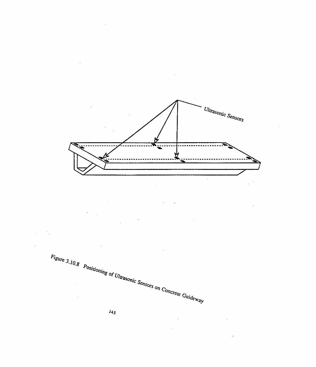
lSune 3.J0 .sA w -
&
nsors0/7 C0.
Cr,e te r> .^ c fe
U s

shown in Fig. 3.10.9. Analysis of these radar signals can provide valuable information about
the condition of the guideway. However, the electromagnetic radar waves are greatly influenced
by the magnetic fields in the Maglev environment, hence a separate non-Maglev test vehicle will
be necessary for data acquisition in the field.
For GPR, metals such as steel and aluminum have a reflection coefficient of -1 and a
transmission coefficient of 0, i.e. radar waves cannot penetrate through metals. Hence, GPR
cannot be used as a NDE technique on steel guideways. Nor can GPR be used if the
concrete/composite guideway is covered with aluminum sheets (for shielding of the magnetic
radiation).
GPR Monitoring System
The main components of the GPR system are shown in Fig. 3.10.10. These components
are generally housed in a van which is then run over the pavement of bridge deck at speeds
varying from 16 to 32 kmph (10 to 20 mph). This system can be adapted for use on a Maglev
guideway by using a special test vehicle.
Each radar antenna is about 203.2 mm (8 inches) wide and can scan an area of 0.093 m2
(1 sq. ft.) at a time. Because the distresses will most likely occur along the line of support of
the overhang (as explained in Section 3.10.2.4), two antennas will be sufficient to scan the
guideway in a single pass.
3.10.2.6 Infrared Thermography
Infrared thermography senses the emission of thermal radiation from the specimen and
produces a visual image of the surface from this thermal signal. Infrared thermography can be
146

Antenna
Dolam lnatlon at Top Mat of Rabara
Fig. 3.10.9 Radar Response from Test on Defective Specimen (Clemena, 1991)
147
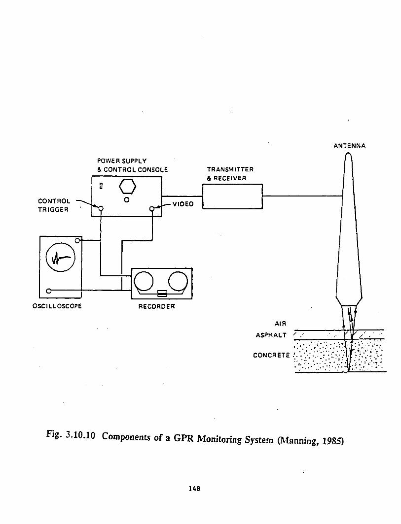
ANTENNA
Fig. 3.10.10 Components of a GPR Monitoring System (Manning, 1985)
148
used to identify delaminated or debonded areas in concrete by measuring the temperature
difference between these areas and the surrounding areas of sound concrete (Maser and Roddis,
1990)
Thermography has the advantages of relatively fast data acquisition and easy
interpretation. However, infrared measurements are severely affected by the unpredictable
changes in weather conditions. Defects can be identified only on bright sunny days (or nights
following sunny days) during the solar heating cycle (around 11 a.m. - 3 p.m..) or the cooling
cycle (around 11 p.m. - 3 a.m.). Furthermore, the magnetic fields existing in the Maglev
environment may cause high temperature gradients and their effect on the infrared measurements
has to be properly incorporated in the study.
Infrared Monitoring System
The main components of an infrared monitoring system are:
• Infrared camera and VCR;
• Regular video camera and VCR; and
• Digitization system for the infrared camera with computer and disk storage.
The IR system can be mounted on the Maglev vehicle for scanning the guideway.
However, the speed of the Maglev vehicle is far too high for the camera to read and record
distinguishable temperature differentials. Hence a separate test vehicle which runs at a slower
speed (32-48 kmph [20-30 mph]) is necessary for the IR system. A test vehicle similar to that
used for the GPR system can be used in the IR system. Some manual labor is necessary for data
collection and supervision of the testing procedure.
149
3.10.2.7 Fiber Optic Sensors
Fiber optic sensors can be used to detect microcracks in the guideway, guideway
misalignments, or obstructions on the guideway. For detection of the above, the sensors may
be implemented separately or in conjunction with each other. The main advantage of using fiber
optic sensors is that the strong magnetic field associated with Maglev does not affect the
components of the system. The only components of the system which will be exposed to
magnetic fields are the fiber optic cables, which are not affected by the field. Other electronic
components have to be shielded and placed at a safe distance from the magnetic field.
Another advantage of the system mentioned above is the method of detection. The
sensors only need to detect a decrease in light intensity to determine if a microcrack,
misalignment, or obstruction is present. This feature makes the data analysis both easy and
inexpensive. Modifications may be made to the microcrack detector system in order to detect
strain and temperature, with a penalty of more difficult and expensive data analysis.
3.10.2.7.1 Embedded Fiber Optic Cables to Produce a "Smart Structure"
Fiber optic cables run from inspection stations to the guideway where they are embedded
at critical stress areas, and then return to the inspection station. The inspection stations contain
Light Emitting Diodes (LED) that transmit light through the fibers, phototransistors to detect the
light intensity passed through the fiber, and support devices (i.e., operational amplifiers,
transistors) that amplify the signal for interpretation. The inspection stations can be positioned
either at every joint in the guideway structure, or at intervals of joints as necessary. At least
two fibers run the length (about 24.4 m [80 ft.]) of the guideway. This length does not pose any
major problem, since optical fibers with a length of several miles are being successfully used
for telephone lines.
150
When the structure has cracks at the critical areas, the fiber embedded within the
guideway will experience some deformation. This deformation in the fiber will allow light
which is normally reflected within the fiber to be absorbed in the fiber cladding. This
deformation is known as a microbending loss in the fiber and will decrease the intensity of light
received at the photo-transistor. This decrease in light intensity will trigger a warning signal that
some crack has occurred within that particular section of the guideway. However, experimental
research to determine the minimum crack size that can be detected is yet to be conducted.
The embedded cables in the above configuration could also be used to sense temperature
and strain. A change in either of these would cause a phase change in the light transmitted
through the fiber optic cable. Using interferometric devices, the phase change with respect to
a reference fiber can be determined. The measurement of these parameters would greatly
increase the complexity of data analysis.
3.10.2.7.2 Fiber Optic Guideway Alignment Detector
Fiber optic cables run from inspection stations to the guideway joints, through deformers,
and return to the inspection stations. The inspection stations contain Light Emitting Diodes
(LED) that transmit light through the fibers, photo-transistors to detect the light intensity passed
through the fiber, and support devices (i.e., operational amplifiers, transistors) that amplify the
signal for interpretation. These inspection stations are usually very small units and can be
positioned either at every joint in the guideway structure or at intervals of joints as necessary.
Two fibers are placed at each guideway joint.
If the guideway becomes misaligned due to settlement or other causes, the deformers
press against the optical fibers. The deformers have teeth that induce microbending losses when
pressed against the optical fibers. The deformation in the optical fiber will cause light which
151

is normally transmitted through the fiber to be absorbed by the fiber cladding. The amount of
light absorbed by the cladding is proportional to the deformation of the fiber. The light received
at the phototransistor will decrease, and a warning signal is generated.
3.10.2.7.3 Obstruction Detection on the Guideway
Fiber optic cables run from inspection stations to the guideway and terminate at lenses
which focus the light and project it across the guideway to form light emitters. A second set
of cables runs from inspection stations to the guideway and terminates in lenses which gather
the light sent by the emitters. These light receivers carry the light back to the inspection station.
The inspection stations contain Light Emitting Diodes (LED) that transmit light through the
emitters, phototransistors to detect the light intensity passed through receivers, and support
devices (i.e. operational amps, transistors) that amplify the signal for interpretation. The
inspection stations can be positioned either at every joint in the guideway structure, or at
intervals of joints as necessary.
An array of light emitters and receivers are positioned on the guideway as shown in
Figure 3.10.11. Any large obstruction on the guideway will break one or more light beams,
resulting in a decrease of light at the phototransistor. A warning signal will then be sent to the
monitoring system. The number of emitters and receivers in the array can be adjusted as
necessary.
4.0 SUMMARY, CONCLUSIONS, AND OPTIONS
The research described in this report represents one part of a comprehensive, long-term
study to assess the engineering, economic, and environmental feasibility of Maglev in the U.S.
152

1-1 o . l l•S,**Olj/f|o <• p .
** (*»i(/evv;■' s,.....n.s’o r s

Previous work in Europe and Japan suggests that the concept is technically feasible and may
offer substantial benefits in terms of certain types of intercity travel. There are, however, a
number of concerns that must be addressed.
A Maglev system consists of essentially four major components: guideway, substructure,
propulsion/guidance/levitation system, and vehicle. The guideway constitutes the major cost
item for the system. The overall objective of this study was to examine existing and innovative
materials and guideway systems and provide an assessment of the most promising systems for
Maglev guideways in terms of performance and cost.
Several conclusions have been drawn and options presented as a result of the research
effort. A brief summary will be presented first, followed by the conclusions and options for
future work.
4.1 SUMMARY
The various Maglev systems under consideration for a ground transport system were
reviewed, summarizing different magnetically-levitated propulsion technologies (e.g., EDS,
EMS, LIM, and LSM). Each Maglev technology possesses distinct advantages and
disadvantages. At this stage, it is premature to rate each system with regard to the overall
technical and economical effectiveness. While all systems seem to be promising, German and
Japanese efforts have seen the most extensive results to date.
The concrete, steel, FRP, and hybrid guideways have been designed under varying load
and serviceability conditions. The governing design aspect of the guideway is the vertical
154

deflection. For an electromagnetic (German) system, the vehicle is suspended only 10 mm
above the guideway, thus allowing only a very limited vertical movement of the guideway under
live load. However, the electrodynamic (Japanese) system has a 100 mm air gap. In general,
all design and performance criteria have to be kept at minimum tolerances to allow the system
to perform successfully. The stringent serviceability limits and performance requirements that
have been established from ACI, AASHTO, and AREA testing and construction specifications,
and other relevant materials should be satisfied during all design and operations and maintenance
phases. The design of each Maglev guideway must account for material component behavior
such as strength, stability, stiffness, fatigue, and flexibility. This should not only apply to the
design of the guideway but also to the design of substructure, footings, vehicle, and functional
components to allow a compatible interaction of each system’s components.
Human response factors related to noise levels, environmental effects, and ride quality
were established, based on the information available in the literature. The loads acting on a
guideway system such as dead loads, dynamic, impact, braking, wind, thermal, centrifugal,
aerodynamic loads, and others were identified. Furthermore, the effects of magnetic field
interference were discussed. The resulting magnetic drag forces can be minimized by properly
designing the reinforcement system, the electro-magnets (ferromagnets), and the conductor
sheets. One way to minimize the magnetic drag forces is by replacing any steel components in
the magnetic fields with non-conductive composite materials.
The Maglev guideway represents an excellent opportunity to incorporate fiber reinforced
plastic rebars as reinforcement and prestressing tendons instead of conventional steel that is
usually used for these tasks. The advantages of using composite materials in the design of a
155
Maglev guideway were highlighted. Composite materials appear to be feasible and highly
compatible not only for use in the reinforcing system in a concrete guideway but also as a major
structural component in a hybrid guideway system.
Consideration has been given to the fabrication, erection, and transportation processes,
utilizing modular construction techniques which should be employed on a systematized basis to
validate any economic feasibility of the construction of a Maglev guideway system. The
construction of a prefabricated concrete guideway module appeared to be the most promising
choice with regard to ease, speed, and cost efficiency of the fabrication and erection.
Modularized precast concrete units can decrease costs and erection time while providing
a better quality end product. Simple span precast concrete units can be used to minimize the
effects of soil settlements and replacement time; however, the ride quality suffers as the number
of structural joints increases. The joints can be reduced by converting simple span guideways
into two or three span guideways; but thermal stresses are more critical in continuous structures
and must be accounted for in the design.
Superstructure! guideway systems made of FRP composite materials have several
advantages over conventional construction materials. First, FRP is lighter than steel and
concrete, thus, the cost and time for construction and transportation are reduced. Composite
materials and systems are corrosion resistant, which reduces maintenance cost. Since composite
materials are nonmagnetic, there are no electromagnetic field effects. On the other hand, the
principal disadvantages of composite materials are their high initial costs and excessive
deflections. Even though composite materials have high strength-to-weight ratio, their stiffness
is low; consequently, the design of the section is governed by stiffness in most cases. The
156

higher damping of composite materials may improve dynamic response but the reduced mass
may cause vibrational problems. To avoid high material costs and buckling problems, composite
sections with concrete or wood cores should be used rather than solid cross sections. The lack
of technical know-how to apply composite materials to civil engineering structures and the lack
of information on joint behavior are areas of concern when using composite materials. The
manufacturing technique for modular units, which is a significant cost factor, is quite attractive
with composites.
Since the buckling analysis showed that a simple box section would not be stable, only
box sections with cross members were chosen for the optimization. There are significant
advantages in using a jointless clamped-clamped design as shown by the amount of material that
is needed to carry the loads for a simply supported system versus a jointless system for Maglev
loading. The depth of the guideway reduces significantly for a jointless system versus a simply
supported system.
When the cost of carbon fibers is compared to the cost of E-glass fibers, the carbon
system is at least six times more expensive. This fact indicates that, even though E-
glass/polyester structures required more material, this was not enough to justify the increased
material cost of a carbon/polyester structure.
In optimizing for weight, unlike the box sections, it was shown that as a result of the
distributed load, the amount of material needed to carry the load was significantly affected by
the boundary conditions. In addition, it was shown that up to a SO percent reduction of material
could be achieved with the jointless design as compared to the simply supported system for both
E-glass/polyester and carbon/polyester laminates. A second optimization on the hybrid truss
157

models was performed with the added constraint that the diameters of the tubes for the vertical
and diagonal members be equal. A review of the data demonstrated that this caused a significant
increase in the material needed to handle the load, indicating that the material is not being used
to its maximum potential. Finally, when the E-glass and carbon fiber systems are compared,
it is found that the materials are not used to their maximum potential even though E-
glass/polyester structures required more material.
Based on a subjective rating survey, the following systems were recommended for further
study: trapezoidal concrete box section with FRP reinforcement; hybrid system with concrete
slabs (reinforced with FRPs); and FRP truss system; and FRP composite cellular deck with cross
bracing (diaphragms).
The hybrid system with concrete decks and FRP trusses offers good damping, strength,
and stiffness characteristics. However, the complexity of the connections and field installation
are two of the disadvantages that must be further evaluated. A very efficient system is the
jointless guideway design (built monolithically with the supports), but in this case the concrete
decks must be prestressed because tensile stresses are developed in the negative moment zones.
The cellular FRP box section with cross members can be fabricated by pultrusion. The
stability analysis indicated that the cross members are needed to prevent buckling of the webs.
A cellular composite section is recommended for construction, but the long-term performance
of the system must be established, and the cost of the structure must be evaluated by including
life-cycle considerations.
After an extensive review and evaluation of economic analysis techniques, the net present
value approach was chosen for the economic evaluation of Maglev guideways. This approach
158
is considered to be superior to all others and provides great flexibility in an analysis.
Due to the extremely small number of existing Maglev systems, very little actual cost
data needed for an evaluation are available. Thus, any cost estimates involve considerable
judgment. In addition, the innovative nature of the designs being proposed also contributes to
making the estimating process more difficult. In terms of capital costs, estimating labor costs
associated with the new materials or construction procedures proved to be the most difficult step.
The lack of available data on the materials and procedures contributes to the difficulty.
The development of maintenance costs for Maglev guideways is also hampered by the
lack of historical data. To date, two basic approaches have been undertaken by estimators in
formulating Maglev maintenance costs. Both techniques utilize a certain percentage of the
capital costs in some form or another. Because of the lack of Maglev data, conventional mass
transit system guideways were examined. This project examined maintenance data from the
Morgantown DPM and applied it to the Maglev guideway situation. This application was in the
form of verification of the rule-of-thumb percentage approach and identification of guideway
maintenance problem areas.
From the study of the various NDT techniques and their applicability to Maglev systems
for guideway monitoring, a number of issues were highlighted. First, the application of NDT
methods for complete monitoring of Maglev guideway systems is very promising. Secondly,
the use of a NDT monitoring system can lead to early detection of distresses, initiating proper
repair steps and preventing the occurrence of disasters. From the study of the various NDT
systems, it is evident that a combination of the various NDT methods will be necessary for a
complete monitoring system. All NDT methods discussed are applicable to concrete structures
whereas only a select number of NDT methods are applicable to composites. Finally,
159

ground penetrating radar, infrared thermography, and optical fibers (embedded sensors) are not
applicable to steel structures.
4.2 CONCLUSIONS
The following conclusions may be drawn from this research study:
1. Sixteen Maglev guideway superstructural systems with closed and open cross
sections were identified, and they were reduced to the following seven systems
for in-depth design evaluations of 80 ft. span length.
a) trapezoidal concrete box section with conventional steel reinforcement;
b) trapezoidal concrete box section with fiber reinforced plastic (FRP)
reinforcement;
c) rectangular concrete box section with conventional steel reinforcement;
d) trapezoidal steel box section;
e) hybrid-system with concrete decking stiffened by steel trusses;
0 hybrid-system with concrete decking stiffened by concrete filled FRP
trusses;
g) all FRP box system.
2. In-depth design evaluations were carried out for the above sections using ten load
conditions and three serviceability criteria.
3. Special emphasis is given to the design of Maglev guideway systems employing
fiber reinforced plastic materials so that magnetic drag forces can be minimized.
4. Based on our internal rating, trapezoidal or rectangular concrete box with FRP
160
reinforcement, hybrid system with FRP trusses stiffened by concrete decks and
all FRP box systems are found to be the best composite material alternatives for
further study.
5. Our literature reviews revealed that modularized construction techniques should
be employed on a systematized basis to attain ease, speed, and cost efficiency of
the fabrication and erection.
6. A review of economic analysis techniques revealed that the net present value
approach is the superior approach to all others.
7. Since the development of maintenance costs for Maglev guideways is hampered
by the lack of data, maintenance data of conventional mass transit system
guideways were examined and found that the guideway maintenance costs are
very low, i.e., 0.03 percent of the original capital costs.
8. The use of a NDT monitoring system will lead to the early detection of distresses
in Maglev guideways, and a combination of the various NDT methods will be
needed for complete monitoring. The ultrasonic method can measure in-situ
stresses in concrete and steel guideways whereas the acoustic emission technique
was found to be most useful in measuring stresses in FRP composites.
4.3 OPTIONS FOR FUTURE WORK
Options for Future Work
This research has identified a number of areas where additional work is needed before
the details of a Maglev guideway can be defined. Some of this effort involves "paper and
161

pencil" type studies using data and/or information which was not available or could not be
acquired during this project. Other issues can only be addressed through laboratory and field
testing and experience. This section outlines the key needs in each of these areas.
A number of design factors were based on limited knowledge. Future research, it is
hoped, will aid the Maglev guideway designers to fully understand some of these phenomena
associated with a Maglev technology. The design examples that were developed as a part of this
effort should be viewed as preliminary and not as in-depth guideway designs. Optimization of
a guideway section, including detailed design specifications and construction drawings, should
be carried out in the future.
Several issues need to be resolved so that the economic analysis can be refined. Follow
up work should address the following areas:
Climatic effects on guideway: It is not clear whether provisions need to be made for
controlling snow and ice on Maglev guideways. If so, the question of whether such a system
would be either internal to the guideway or external needs to be answered. The former may
involve additional construction cost and would certainly mean additional maintenance costs (as
indicated by experience with the Morgantown DPM system).
Future retrofitting of guideway system: As guideway-related components reach the end
of their useful life, complete replacement or retrofitting of certain parts of the system may be
necessary. This would certainly be a major expense that should be included in any economic
analysis. Unfortunately, neither the nature nor the magnitude of this work is known. Additional
information in this regard would be desirable.
162

Construction techniques: The issue of exactly how Maglev guideways will be produced
and installed is a major issue that needs to be resolved. Due to the significant differences in the
guideway designs being proposed, the construction technique being employed could have a
significant influence on the capital costs.
Maintenance cost factor: Because of the lack of Maglev guideway maintenance data,
the use of a maintenance cost factor (or percentage) appears to be necessary. The significant
differences in proposed factors create problems. Additional information needs to be collected
before this issue can be resolved.
NDT techniques: Research is needed to study applications of NDT methods to FRP
structures. Application of Acoustic Emission and Ultrasonics to FRP structures appears very
promising. Research also should be conducted on the effect of strong magnetic fields on NDT
sensor/system response. .
Test plan: In order to fully investigate all the parameters affecting Maglev guideways
and to assess the safety and reliability of the guideway systems, a model test plan was developed
in terms of laboratory, field experiment, and field demonstration phases, and testing under a
variety of conditions is recommended.
Laboratory Phase
Prior to field exposure, testing under controlled conditions would be required. The
optimal laboratory testing phase would include:
163
• Building several structural components (with embedded sensors) in the laboratory
to determine: (1) performance behavior under static, thermal, and dynamic
conditions; (2) thermal, creep and shrinkage of the material, and study of the
fatigue response of various components and numerical evaluations using numerical
techniques; (3) performance of various NDT sensing techniques for their
accuracy and reliability, sensitivity, ease of data acquisition, and quality control
of the curing process; (4) methods for rehabilitation of damaged main
components and replacement of secondary components, and (5) design cost
details of an operational system for nondestructive monitoring.
• Construction of a Magnetic Influence Laboratory to study: (1) the effect of
magnetic field on various components; (2) magnetic drag forces as a function of
area, cover and type (open vs. closed loop) of steel reinforcement; and (3) the
effect of magnetic field on various NDT sensors.
Field Experiment Phase
The field experiment phase would involve testing under actual field conditions with
exposure to the environmental loads. This phase should include:
• Construction of an experimental track to: (1) field test the proposed modular
units and appurtenances associated with the guideway; (2) study the interaction
between the vehicle guideway foundation and soil to establish tolerable limits for
operation, ride quality, and human comfort and to establish tolerable movements
of the guideway with respect to stress and safety of the track; (3) measure noise,
164
aerodynamic forces, and forces due to track irregularities in the field and
integrate them in the Maglev guideway design; (4) measure magnetic drag forces
as a function of the amount of ferrous material in the guideway; and (5) study
the viability of various NDT methods (including embedded fiber optic cables and
microbending deforming teeth) as a complete monitoring system.
Field Demonstration Phase
After extensive testing of the Maglev components in the laboratory and the whole system
in the field, a prototype (e.g., 20-mile-long test track) could be built as a demonstration system
with limited access to passengers and exposure to actual field conditions to evaluate
performance.
165

5.0 REFERENCES
AASHTO "Standards Specifications for Highway Bridges," 13th ed., Washington, D.C., 1983.
AASHTO, "Standard Specifications for Highway Bridges," 14th ed., 1989.
AEG Aktiengesellschaft, D-1000 Berlin 33, 1990.
Ahmad, S.H., and Plecnik, J.M., "Transfer of Composite Technology to Design and Construction of Bridges," FHWA Report, 1989.
American Concrete Institute, "Building Code Requirements for Reinforced Concrete," ACI, 318- 389, Detroit, MI, 1989.
American Concrete Institute, "State-of-the-Art Report on Concrete Guideways," ACI, 358R-80, Detroit, MI, 1980.
American Iron and Steel Institute, "Steel Structures for Mass Transit," Washington, D.C., 1977.
American Railway Engineering Assoc., "Manual for Railway Engineering," Chapter 7, Timber Structures, Washington, D.C., 1990.
American Society of Civil Engineers, "Recommended Design Loads for Bridges," Committee on Loads and Forces on Bridges of the Structural Division, Journal of Structural Division, ASCE, pp. 1161-1213, July, 1981.
Atherton, D.L., et al., "Design Study of the Guideway for the Canadian High Speed Magnetically Levitated Vehicle System." Journal of Advanced Transportation, Vol. 16, No. 1, pp. 25-57, Spring, 1982.
Au, Tung, and Au, Thomas, "Engineering Economics for Capital Investment Analysis," Allyn and Bacon, Inc., Boston, MA, 1983.
Ballinger, C., "Structural FRP Composite." Civil Engineering, Vol. 60, No. 7, pp. 63-65, July,1990.
Barbero, E.J., "Pultruded Structural Shapes - From the Constituents to the Structural Behavior," SAMPE Journal, p. 2711, 1991.
Barbero, E.J., and Tomblin, J., "Buckling Testing of Composite Columns," in Press, AIAA, 1992.
Bechtel Corporation, "Proposal for Build and Operate-Franchise for a Super-Speed Ground Transportation Project," Califomia-Nevada Super-Speed Train Commission, July, 1990.
166
"Benefits of Magnetically Levitated High Speed Transportation for the United States," Vol. I and II, The Maglev Technology Advisory Committee, June, 1989.
Burnside, P.H., "Design Optimization of Fiber Reinforced Composite Material Guideway for Maglev," Thesis, West Virginia University, Morgantown, WV, 1992.
Budd Company, "Executive Summary - Las Vegas to Los Angeles High Speed - Super Speed Ground Transportation System, Feasibility Study," Pittsburgh, PA, January, 1983.
Canadian Institute of Guided Ground Transport, "Maglev Technology Assessment, Task 9.1: Examination of Estimated Costs, Initial Order of Magnitude Review. Super-Speed Ground Transportation System, Las Vegas/Southem California Corridor, Phase II," CIGGT 86-15, 1986.
Cortes, Comeres, N., "Will Maglev Ever Get Off the Ground in the U.S.," Mechanical Engineering, pp. 58-63, Oct., 1988.
CSX Transportation, "Track Geometry Manual," M/W Services, Jacksonville, FL, Jan., 1990.
Davis, L.C., et al., "Technical Feasibility of Magnetic Levitation as a Suspension System for High Speed Ground Transportation Vehicles," U.S. Department of Transportation, Report FRA-RT-72-40, 1972.
Eck, R. W. and Hyre, J.B., "Draft Final Report - Task 4.5, Analysis of Costs and Assessements of Economic Impact of Maglev Guideways," Dept, of Civil Engineering, West Virginia University, Morgantown, WV, June, 1992.
Federal Highway Administration, "Overweight Vehicles - Penalties and Permits, An Inventory of State Practices 1990." Report submitted to Congress from Secretary of Transportation, FHWA-MC-92-OQ9, April, 1992.
Faza, S., et al., "Long Term Degradation of FRPs Under Harsh Environment," Constructed Facilities Center Report, West Virginia University, Morgantown, WV, 1992.
Faza, S., and GangaRao, H.V.S., "Bending and Bond Behavior and Design of Concrete Beams," Report Submitted to WVDOH/FHWA, Charleston, WV, 1992.
Fried, N., "Degradation of Composite Material: the Effects of Water on Glass Reinforced Plastics," Mechanics of Composite Materials, Proceeding of the Fifth Symposium on Naval Structural Mechanics, Pergamon Press, NY, 1967.
Fryba, L., "Vibrations of Solids and Structures Under Moving Loads," Noordhoff International Publishing, Groningen, 1970.
GangaRao, H.V.S., "Notes from German Engineers," Germany, Aug., 1991.
167

GangaRao, H.V.S., "Research and Development of Stressed Timber Bridge Systems of West Virginia University," Vol. 1, No. 3, pp. 7-10, Wood Design Focus, World Forestry Center, Portland, OR, Fall, 1990.
GangaRao, H.V.S., and Dlugos, S., "Testing and Evaluation of a Precast Concrete Panel System," 10th CIB, 86 Congress, Advancing Building Technology, Washington, D.C., 1986.
GangaRao, H.V.S., and Moulton, L.K., "Tolerable Movement Criteria for Highway Bridges," Public Roads, Vol. 44, No. 4, pp. 32-39, March, 1981.
GangaRao, H.V.S., and Narendra, B. Taly, "Conceptual Super-structural Systems for Short- span Bridges," Transportation Engineering Journal, ASCE Vol. 104, pp. 13492-13505, Jan., 1978.
Green, A., "Glass Fiber Reinforced Composites in Building Construction," Transportation Research Record No. 118, pp. 73-76, Washington, D.C., 1987.
Green, A., and Bisavnsin, T., "Building Construction Materials," Advanced Thermoset Composites, Edited by J.M. Margolis, pp. 249-271, Van Nostrand Reinhold, Co., NY, 1986.
Hilliges, D., and Schambeck, H., "The Concrete Guideway," A Report, 1989.
Hilliges, Dieter, et al., "Der Fahrway der Transrapid-Versuchsanlage Emsland," (TVE) Jahrgang, 105, 1981, Heft 7/8, Juli/August.
Hyre, Brad, "Estimating Maglev Guideway Maintenance Costs Using Conventional Transit System Data," Thesis, West Virginia University, Morgantown, WV, 1992.
Kakihara, R., Kamiyoshi, M., Kumagai, S., and Noritake, K., "A New Aramid Rod for the Reinforcement of Prestressed Concrete Structures," Advanced Composite Materials in Civil Engineering Structures, Edited by S.L. Iyer, ASCE, pp. 132-142, NY, 1991.
Kim, Y., Davalos, J., and Raju, Penmatsa, "Design Details of Steel and Hybrid Guideway Systems-Personal Computations," Constructed Facilities Center, West Virginia University, 1992.
Kodiak, Fiberglass Reinforced Plastic Rebar Data Sheet, International Grating, Inc., Houston, TX, 1989.
Lubin, G., Handbook of Composites, Van Nostrand Reinhold, NY, 1981.
M-Bahn, AEG, "The Innovative Magnetic Transit System M-Bahn."
168

Masada, E., et. al., "Present Status of Maglev Development in Japan and HSST-03 Project, International Conference on Maglev Transportation, Now and for the Future, 1984, held Solihull, West Midlands, England, Mechanical Engineering Publications, pp. 9-22, London, 1984.
McConnell, V.P., "In Building and Construction Attitudes Are Changing," Plastic Forum, pp. 19-31, Sept., 1990.
McGhee, K.K., "Optimum Design of Bridge Deck Panels Using Composite Materials," Master’s of Science Thesis, Dept, of Civil Engineering, University of Virginia, Charlottsville, VA, 1990.
Merrit, Frederick, et al., "Building Engineering and Systems Designs," 2nd ed., Van Nostrand Reinhold, NY, 1990.
Mikami, K., et al., "Fatigue Characteristics of Concrete Beams Reinforced with Braided AFRR Rods," Transactions of the Japanese Concrete Inst., Vol. 12, 1990.
"Moving America," New Directions, New Opportunities, Vol. 1, Building the National Transportation Policy, United States Department of Transporation, 1989.
Mustow, S. N., "Maglev at Birmingham Airport," International Conference on Maglev Transport Now and for the Future," 1984, held at Solihull, West Midlands, England, Mechanical Engineering Publications, pp. 127-136, London, 1984.
"National Maglev Initiative," Govt.-Industry Workshop Final Report, U.S. Army Corps of Engineers, Nov., 1990.
Phelan, Randal S., "Construction and Maintenance Concerns for High Speed Maglev Transportation Systems," Master’s Thesis, Massachusetts Institute of Technology, Cambridge, MA, June, 1990.
Plast Bau, "Siteco Technical Systems for Buildings," M. Turchin, Chieti Scodo, Italy, 1990.
Pleimann, L.G., "Strength, MOE, and Bond of Deformed FRP Rods," Advanced Composite Materials in Civil Engineering Structures, Edited by S.L. Iyer, ASCE, pp. 99-110, NY,1991.
Rhodes, R.G., and Mulhall, B.E., "Magnetic Levitation for Rail Transport," Clarendon Press, Oxford, 1981.
Schwindt, G., and Kindmann, R., "The Steel Guideway," A Report, 1990.
169

Sheppard, David A., and Phillips, William R., "Plant-cast, Precast and Prestressed Concrete," 3rd ed., McGraw-Hill, New York, 1989.
Smallowitz, H., "Reshaping the Future," Civil Engineering, ASCE, pp. 38-41, May, 1985.
Sotiropoulos, S., GangaRao, H.V.S., and Mongi, A., "Theoretical and Experimental Evaluation of FRP Components and Systems," Accepted by the Journal of Structural Engineering, ASCE, to be printed in 1993.
Stratfull, R.F., "A Manual for Corrosion Control of Bridge Decks," Report No. FHWA- Corrosion Engineering, 1, FHWA, Feb., 1984.
Tomblin, J., "A Universal Design Equation for Pultruded Composite Columns," M.S. Thesis, West Virginia University, Morgantown, WV, 1992.
"Transrapid: Magnetic Levitation Train, the Technology and the System," Maunet Schnellbahn, A.G., Offentlichkeitsarbeit, Postfoch 102969, 3500 Kassel, Feb., 1991.
Urban Mass Transportation Administration, Supplement IV Cost Experience of Automated Transit Systems, 1976-1980, UMTA-MA-06-0069-81-2, Washington, D.C., July, 1981.
U.S. Army, "Economic Analysis Handbook," United States Department of Defense, Washington, D.C., 1974.
Vega Technologies, Inc., "Fiberglass Reinforced Plastic Rebar Data sheet," Marshall, AK, 1988.
Walker, W., "Vibration and Deflection of Steel Bridges," Engineering Journal AISC, pp. 20-31, Jan. 1971.
Warszawski, A., "Industrialization and Robotics in Building," Harper and Row Publishers, NY, p. 12, 1990.
Wendlik, Ralf, "Design and Construction of Concrete Guideway for Maglev Applications," M.S. Problem Report, West Virginia University, Morgantown, WV, 1992.
Wolff, R. and Miesseler, H.J., "Using Fiber Composite Materials for More Durable Concrete Structures," IABSCE Congress, Lisbon, Vol. 57/2, pp. 587-591, 1989.
170

)
APPENDIX A
CONCEPTUAL MAGLEV GUIDEWAY SYSTEMS
A review of literature has shown (GangaRao, 1978) how different materials (concrete,
steel, others) lend themselves to a systems approach toward the construction of bridges or
elevated guideways. Several innovative guideway systems (Figs. A1 through A16) have been
identified from our literature review as feasible alternatives for elevated Maglev guideways. In
addition, several feasible cross-sectional shapes (Figs. A17 and A18) have been selected for
possible implementation with the guideway systems. The sixteen guideway systems have been
broadly classified as beam or frame systems (Figs. Al, A2, and A7 through A13), cable
stiffened beam systems (Figs. A5, A6, and A7 through A14) and deck stiffened truss systems
(Figs. A3, A4, A15, and A16). Similarly, Figures A17 and A18 provide several conceptual
closed and open cross sections that can be evaluated with respect to beam and frame systems.
It should be noted that cable-stiffened beam systems and the space truss system have been
eliminated from our study because structural complexities involved routinely maintaining such
superstructural systems. Other superstructure! systems such as the beam system with over hangs
(Fig. A2) and the frame systems (Figs. A7 through A13) are considered to be variations of
simply supported beam systems. Therefore, a simple beam type system (Fig. Al) for different
cross-sectional shapes (rectangular and trapezoid) and materials (concrete reinforced with steel
or FRP, and all steel) were selected for in-depth analyses and design under Maglev loads. In
addition, guideway systems with steel truss or FRP tubular truss members filled with concrete
(Fig. A15) were selected for in-depth analyses and design. Finally, an all FRP box system was
selected, also for further investigation because of increasing use of composites in construction.
Thus, a total of seven superstructural guideway systems were selected for final evaluations and
presented in Section 3.3.
171

17
2
Fig. A1 Simple Beam SystemNote: Refer to Figures A17 & A18 for Cross Section

17
3
Fig. A2 Simple Beam System With Overhang(Balanced Cantilever Construction)
Note: Refer To Figures A17 & A18 for Cross Section

17
4
C o n c r e t e D e c k
Fig. A3 Simple Truss SystemNote : Refer to Figures A15 & A16 for Cross Section
f
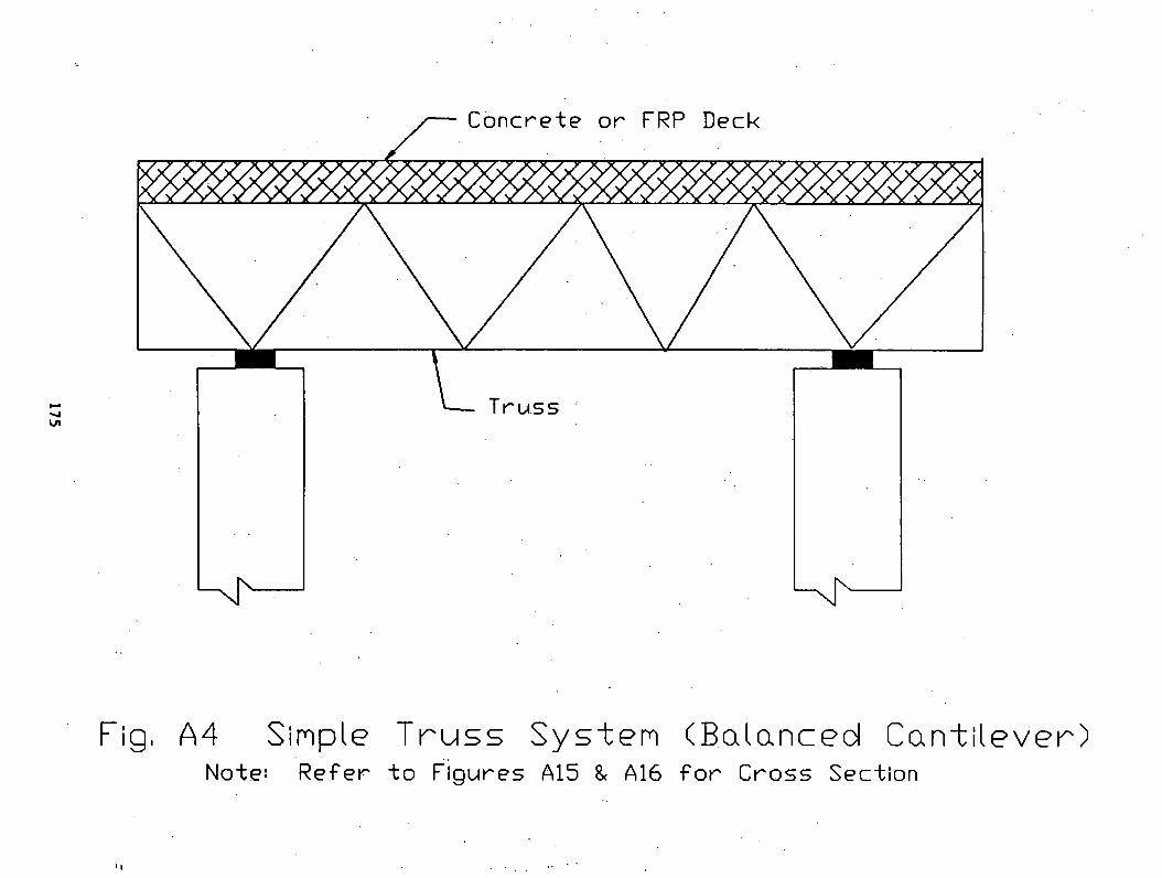
175
A 4 S i m p l e T r u s s S y s t e m
N o te : R e f e r t o F i g u r e s A15 & A16
( B a l a n c e d C a n t i l e v e r )
f o r C r o s s S e c t i o n

17
6
C o n c r e t e D e c k
Fig. A5 Cable Stiffened King Post System

177
Concrete Deck(
Fig.A6 Cable Stiffened Queen Post System

17
8
C o n c r e t e D e c k
F i g , A 7 R i g i d F r a m e S y s t e m w i t h o v e r h a n g
N o t e : T h e s y s t e m i s c o n s i d e r e d w i t h o r w i t h o u t o v e r h a n g s

17
9
F i g . A 8 F l a t A r c h w i t h o v e r h a n g
N o t e : T h e a b o v e s y s t e m c a n b e w i t h e n d r o l l e r s u p p o r t s o r h i n g e
j o i n t In t h e s u p e r s t r u c t u r e ,

180
C o n c r e t e D e c k
Fig. A 9 T w o S p a n C o n t i n u o u s B e a n S y s t e n
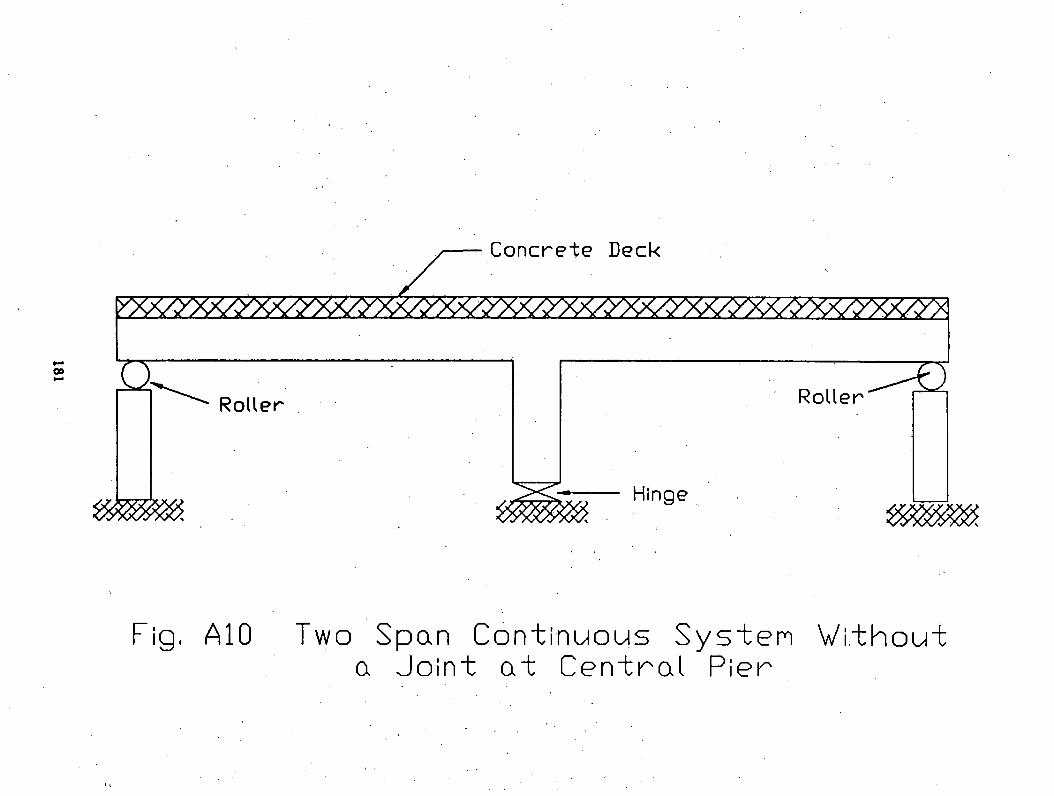
F i g , A 1 0 T w o S p a n C o n t i n u o u s S y s t e m W i t h o u t
a J o i n t a t C e n t r a l P i e r
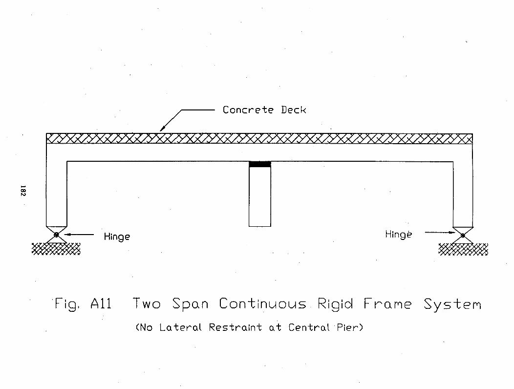
182
C o n c r e t e D e c k
F i g , A l l T w o S p a n C o n t i n u o u s R i g i d F r a m e S y s t e m
( No L a t e r a l R e s t r a i n t a t C e n t r a l P i e r )

C o n c r e t e d e c k
Fig, A12 T h r e e Span Cont inuous Bean S y s te m

•781
Fig, A13 T h r e e S p a n C o n t i n u o u s Rig id F r a m e S y s t e m
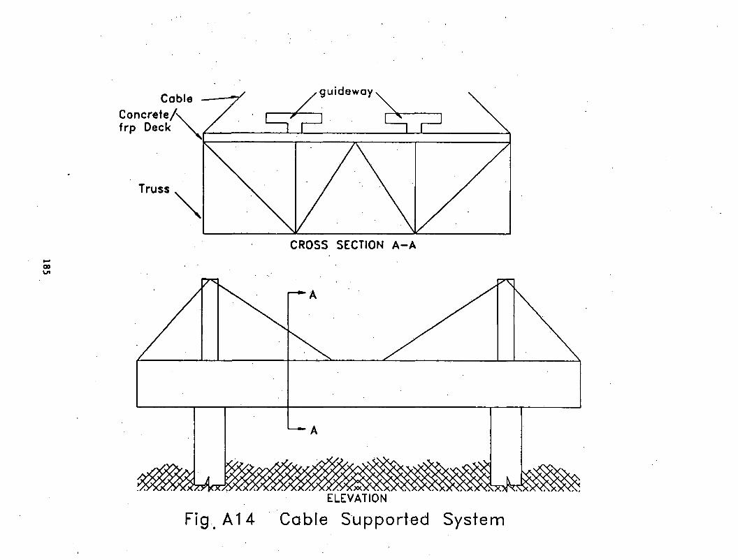
ELEVATION
Fig A14 Cable Supported System
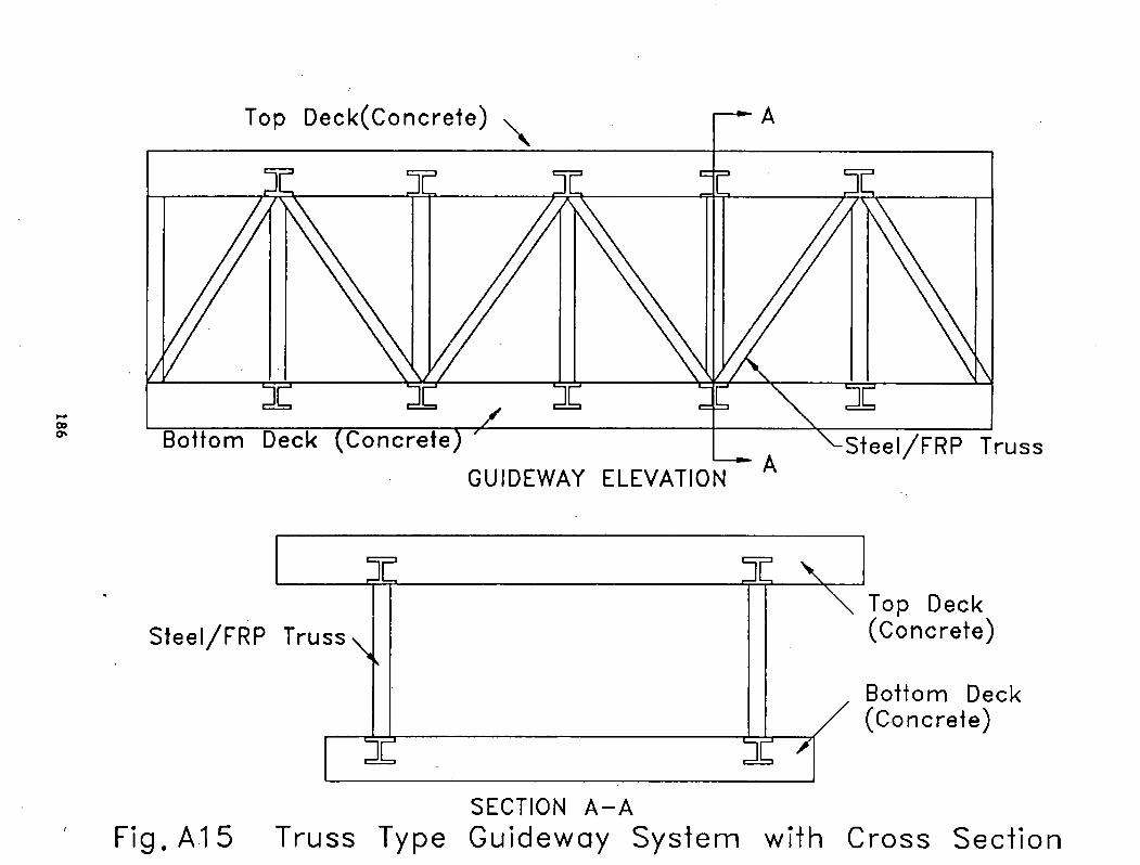
186
SECTION A -AFig. A15 Truss Type Guideway System with Cross Section
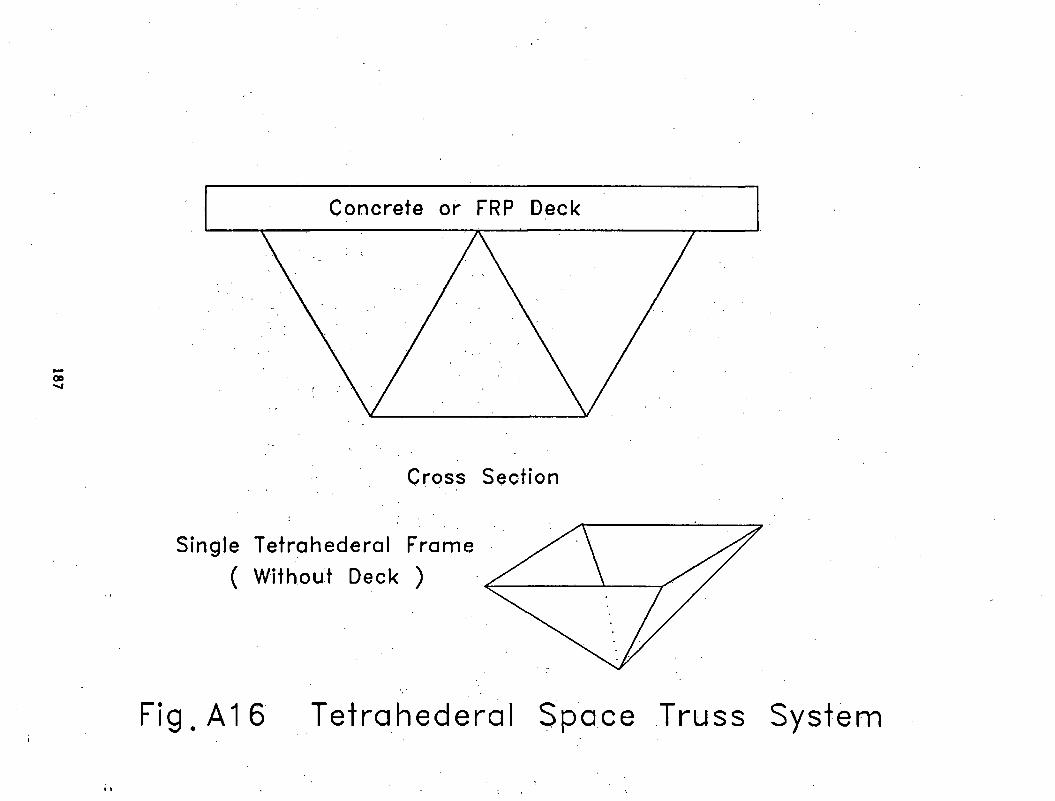
Cross Section
Single Tetrahederal Fra ( Without Deck )
g . A 1 6 Tetrahederal Space Truss System
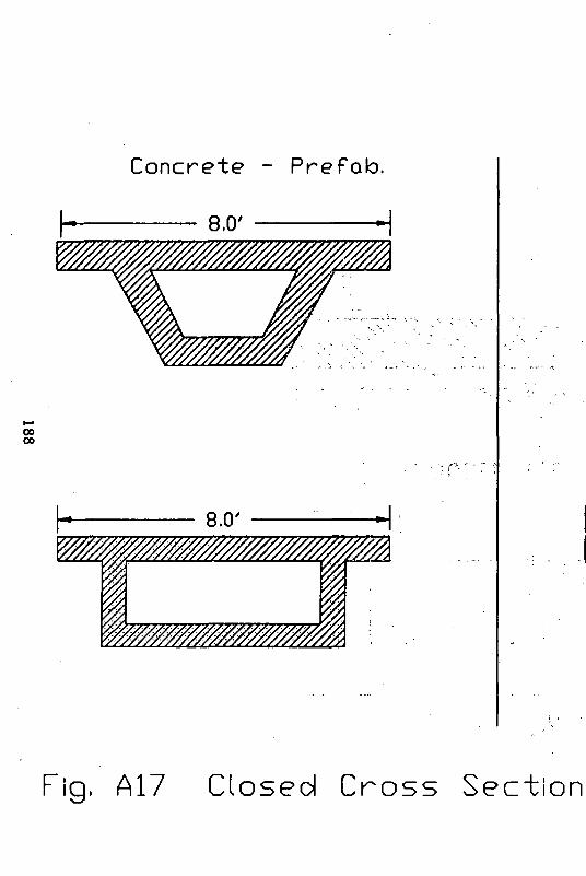
C o n c r e t e - P r e f a b .
8 .0 '
Fig, A17 C lo sed C r o s s S e c t io n
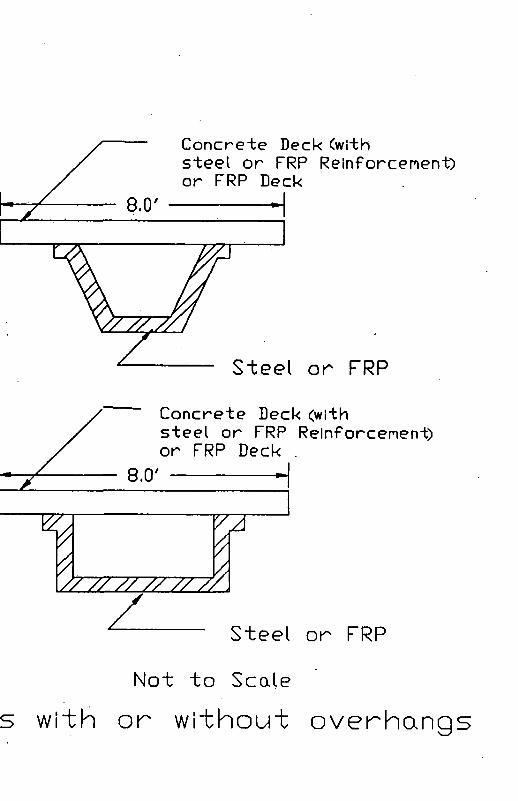
C o n c r e t e D e c k ( w i t hs t e e l o r F R P R e i n f o r c e m e n t )o r F R P D e c k
C o n c r e t e D e c k ( w i t hs t e e l o r F R P R e i n f o r c e m e n t )o r F R P D e c k .
Steel or FRP
Not to Scale
w i " t h o r w i t h o u t o v e r h a n g

189
-- ------------------------ ------------------------ — 8 . 0 ’ ----------- ----------------------------------=-------- --
i
a n » , |
- k• t . u
r1
DOUBLE TEE (CONCRETE)
Concrete Deck
Steel Beam ^ (not to scale)
Fig.AIS Open Cross Sections
• i

State-of-the-Art Assessment of Guideway Systerms for MAGLEV Applications, US DOT, FRA, NMI, GangaRao, Barbero, Chen, Davalos, Eck, Halbe, Kinkhachorn, Raju, Spryakos, 1992 -11-Advanced Systems