Embed Size (px)
Citation preview
May 11, 2004 SECA Annual Workshop Boston 1
SECA Annual Workshop
10kWe SOFC Power System Commercialization Program
ProgressMay 11, 2004Boston, MA
Dan Norrick Manager Advanced Development
Cummins Power Generation
May 11, 2004 SECA Annual Workshop Boston 2
• Cummins Power Generation
• Cummins - SOFCo Team
• SECA Program Progress– System Design & Application
– Cell and Stack
– Hot Box
– Balance of Plant
– Controls & Power Electronics
May 11, 2004 SECA Annual Workshop Boston 3
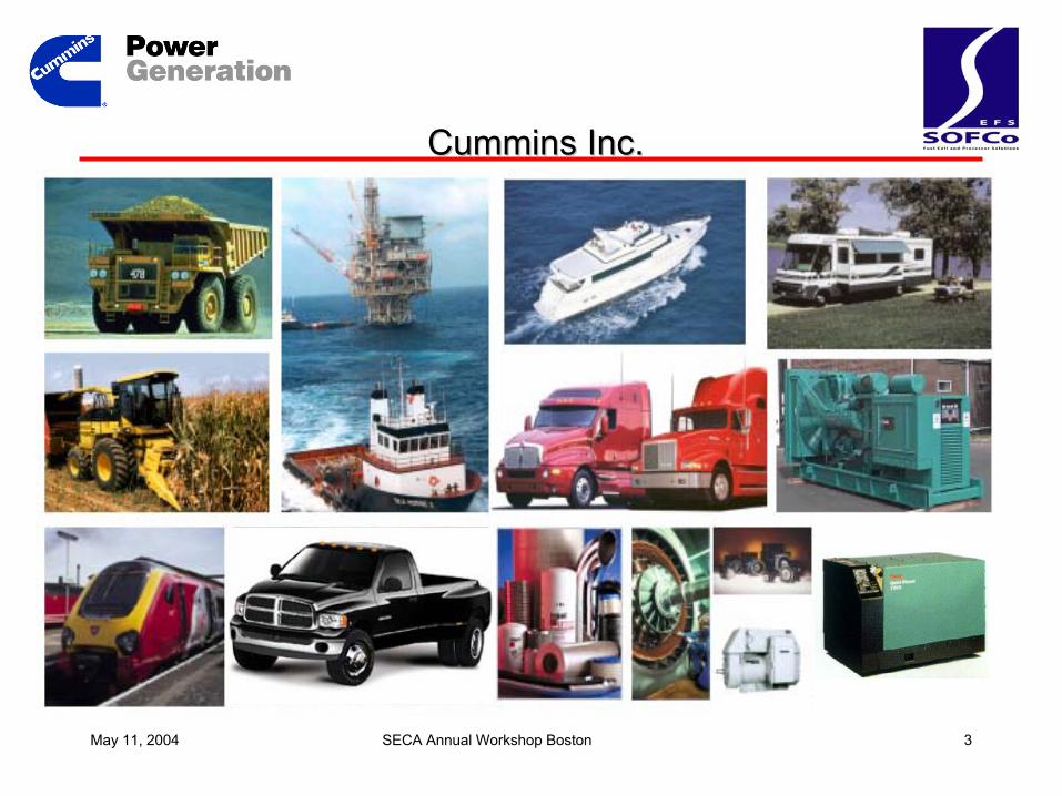
Cummins Inc.Cummins Inc.
May 11, 2004 SECA Annual Workshop Boston 4
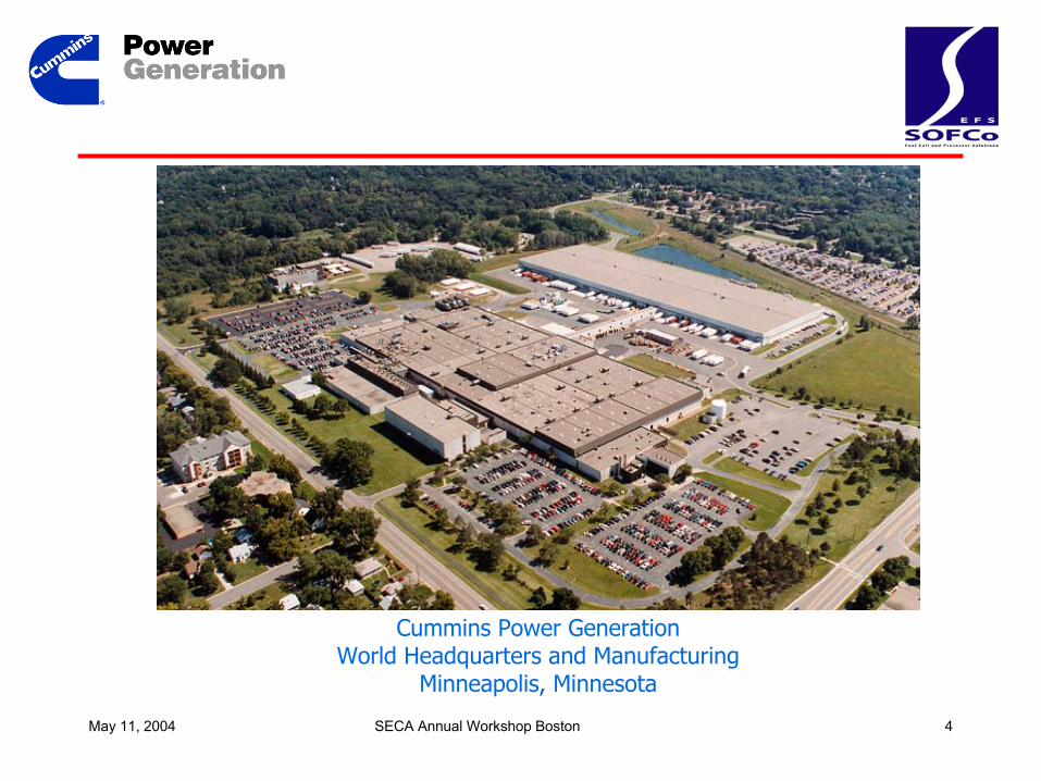
Cummins Power GenerationWorld Headquarters and Manufacturing
Minneapolis, Minnesota

May 11, 2004 SECA Annual Workshop Boston 5
Cummins Power Generation
Variable Speed Gensets
Micro-Turbine Gensets
Controls, Power Electronics, Switches, Switchgear
Diesel and Gas Engine Gensets, CHP Systems
Diesel, Lean Burn and Stoichiometric Gas Engines
Noise Attenuated Gensets
Developingand manufacturing a
wide range ofpower generation
equipment ...
May 11, 2004 SECA Annual Workshop Boston 6
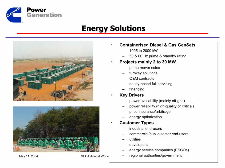
• Containerised Diesel & Gas GenSets – 1005 to 2000 kW– 50 & 60 Hz prime & standby rating
• Projects mainly 2 to 30 MW– prime mover sales– turnkey solutions– O&M contracts– equity-based full servicing– financing
• Key Drivers– power availability (mainly off-grid)– power reliability (high-quality or critical)– price insurance/arbitrage– energy optimization
• Customer Types– industrial end-users– commercial/public-sector end-users– utilities– developers– energy service companies (ESCOs)– regional authorities/government
Energy SolutionsEnergy Solutions
May 11, 2004 SECA Annual Workshop Boston 7
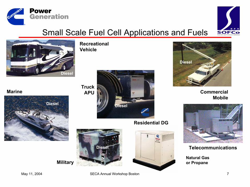
Small Scale Fuel Cell Applications and FuelsRecreational Vehicle
Truck APUMarine Commercial
Mobile
Military
Residential DG
Telecommunications
Diesel
Diesel Diesel
Diesel
Diesel
Natural Gas or Propane
Diesel
May 11, 2004 SECA Annual Workshop Boston 8
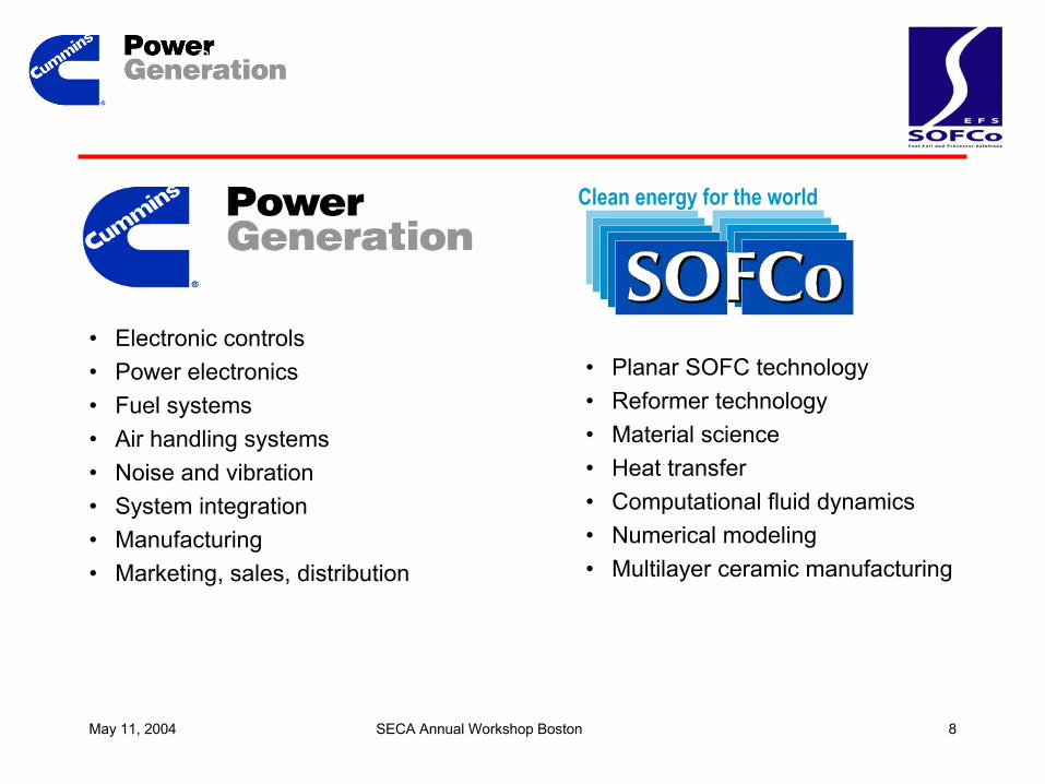
CPG – SOFCo Team
• Electronic controls• Power electronics • Fuel systems• Air handling systems• Noise and vibration• System integration• Manufacturing• Marketing, sales, distribution
• Planar SOFC technology • Reformer technology• Material science• Heat transfer• Computational fluid dynamics• Numerical modeling• Multilayer ceramic manufacturing
Clean energy for the world
May 11, 2004 SECA Annual Workshop Boston 9
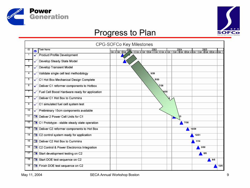
Progress to Plan
May 11, 2004 SECA Annual Workshop Boston 10
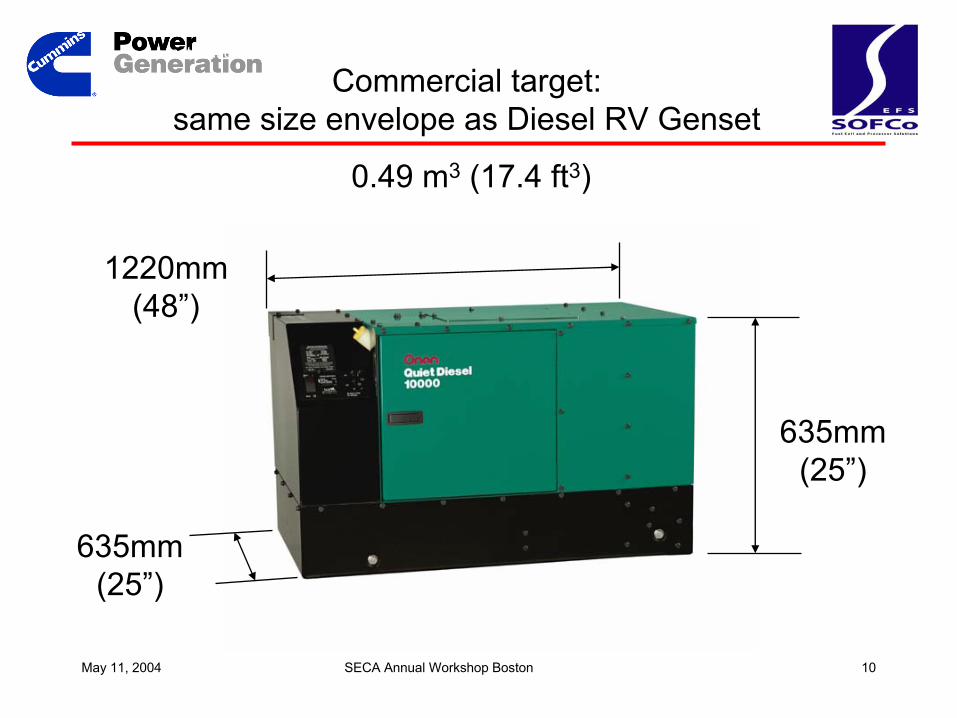
Installation
Commercial target: same size envelope as Diesel RV Genset
0.49 m3 (17.4 ft3)
635mm(25”)
635mm(25”)
1220mm(48”)
May 11, 2004 SECA Annual Workshop Boston 11
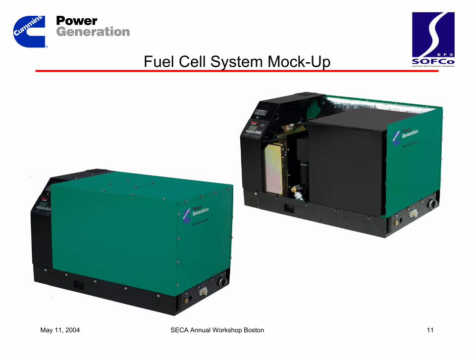
Fuel Cell System Mock-Up
May 11, 2004 SECA Annual Workshop Boston 12
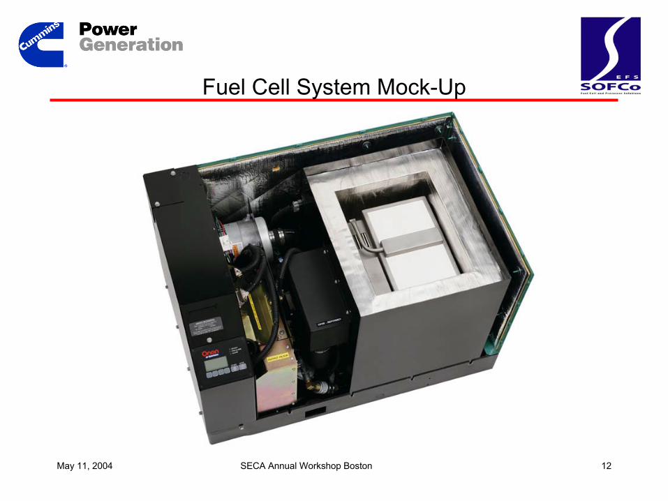
Fuel Cell System Mock-Up
May 11, 2004 SECA Annual Workshop Boston 13
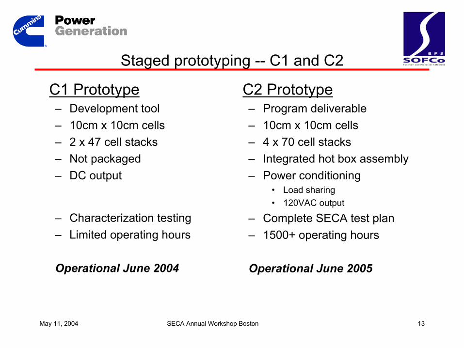
Staged prototyping -- C1 and C2
C1 Prototype– Development tool – 10cm x 10cm cells– 2 x 47 cell stacks– Not packaged– DC output
– Characterization testing– Limited operating hours
Operational June 2004
C2 Prototype– Program deliverable– 10cm x 10cm cells– 4 x 70 cell stacks– Integrated hot box assembly– Power conditioning
• Load sharing• 120VAC output
– Complete SECA test plan– 1500+ operating hours
Operational June 2005
May 11, 2004 SECA Annual Workshop Boston 14
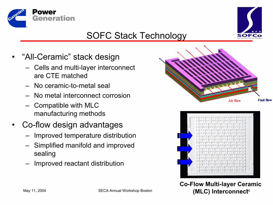
SOFC Stack Technology
• “All-Ceramic” stack design– Cells and multi-layer interconnect
are CTE matched– No ceramic-to-metal seal – No metal interconnect corrosion– Compatible with MLC
manufacturing methods
• Co-flow design advantages– Improved temperature distribution– Simplified manifold and improved
sealing– Improved reactant distribution
Air flow Fuel flowAir flow Fuel flow
Co-Flow Multi-layer Ceramic(MLC) Interconnect
May 11, 2004 SECA Annual Workshop Boston 15
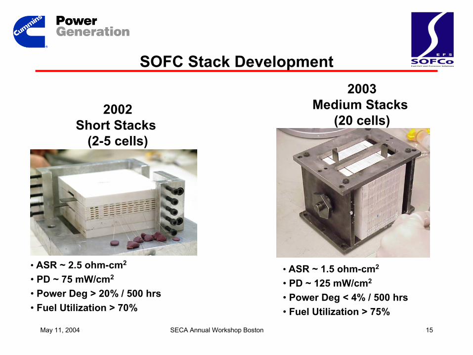
SOFC Stack Development
2002Short Stacks
(2-5 cells)
2003Medium Stacks
(20 cells)
• ASR ~ 2.5 ohm-cm2
• PD ~ 75 mW/cm2
• Power Deg > 20% / 500 hrs• Fuel Utilization > 70%
• ASR ~ 1.5 ohm-cm2
• PD ~ 125 mW/cm2
• Power Deg < 4% / 500 hrs• Fuel Utilization > 75%
May 11, 2004 SECA Annual Workshop Boston 16
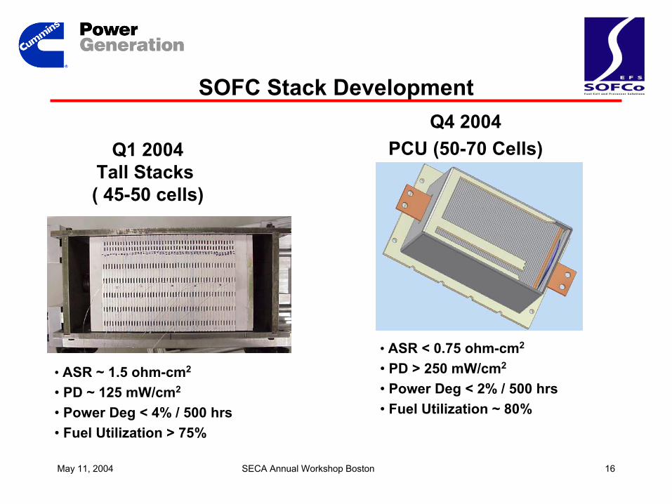
SOFC Stack Development
Q1 2004Tall Stacks ( 45-50 cells)
Q4 2004PCU (50-70 Cells)
• ASR ~ 1.5 ohm-cm2
• PD ~ 125 mW/cm2
• Power Deg < 4% / 500 hrs• Fuel Utilization > 75%
• ASR < 0.75 ohm-cm2
• PD > 250 mW/cm2
• Power Deg < 2% / 500 hrs• Fuel Utilization ~ 80%
May 11, 2004 SECA Annual Workshop Boston 17
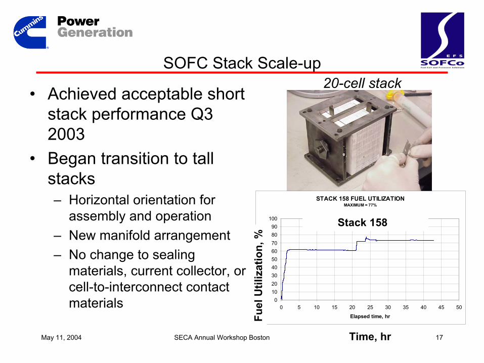
SOFC Stack Scale-up
• Achieved acceptable short stack performance Q3 2003
• Began transition to tall stacks– Horizontal orientation for
assembly and operation– New manifold arrangement– No change to sealing
materials, current collector, or cell-to-interconnect contact materials
20-cell stack
STACK 158 FUEL UTILIZATIONMAXIMUM = 77%
0102030405060708090
100
0 5 10 15 20 25 30 35 40 45 50
Elapsed time, hr
Fuel
Util
izat
ion,
%
Time, hr
Fuel
Util
izat
ion,
%
Stack 158
May 11, 2004 SECA Annual Workshop Boston 18
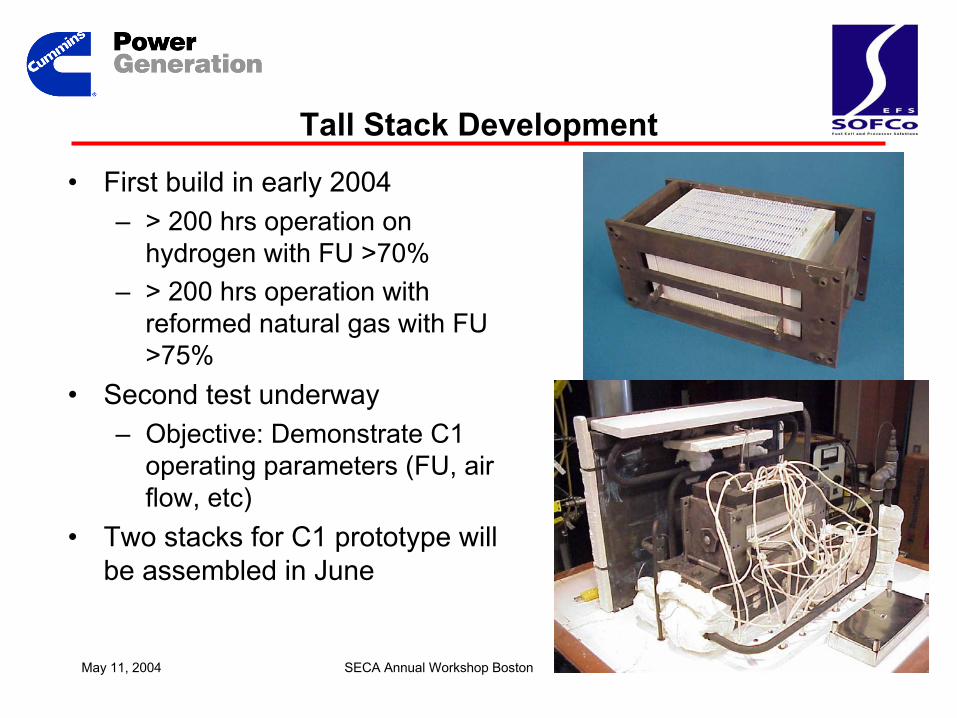
Tall Stack Development
• First build in early 2004– > 200 hrs operation on
hydrogen with FU >70%– > 200 hrs operation with
reformed natural gas with FU >75%
• Second test underway– Objective: Demonstrate C1
operating parameters (FU, air flow, etc)
• Two stacks for C1 prototype will be assembled in June
May 11, 2004 SECA Annual Workshop Boston 19
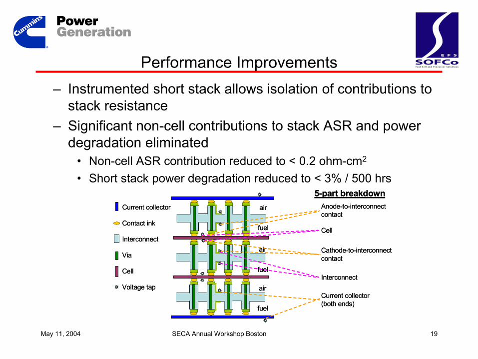
Performance Improvements– Instrumented short stack allows isolation of contributions to
stack resistance– Significant non-cell contributions to stack ASR and power
degradation eliminated• Non-cell ASR contribution reduced to < 0.2 ohm-cm2
• Short stack power degradation reduced to < 3% / 500 hrs
Anode-to-interconnectcontact
Interconnect
Via
Cell
Voltage tap
Platinum ink line
Contact ink
Current collector
air
air
air
fuel
fuel
fuel
Interconnect
Cathode-to-interconnectcontact
Cell
5-part breakdown
Current collector(both ends)
Anode-to-interconnectcontact
Interconnect
Via
Cell
Voltage tap
Platinum ink line
Contact ink
Current collector
air
air
air
fuel
fuel
fuel
Interconnect
Cathode-to-interconnectcontact
Cell
5-part breakdown
Current collector(both ends)
May 11, 2004 SECA Annual Workshop Boston 20
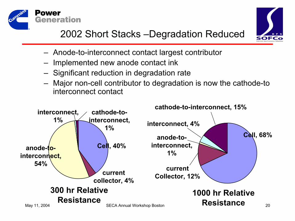
2002 Short Stacks –Degradation Reduced
– Anode-to-interconnect contact largest contributor– Implemented new anode contact ink– Significant reduction in degradation rate– Major non-cell contributor to degradation is now the cathode-to
interconnect contact
anode-to-interconnect,
54%
Cell, 40%
300 hr RelativeResistance
currentcollector, 4%
cathode-to-interconnect,
1%
interconnect,1%
Cell, 68%
cathode-to-interconnect, 15%
currentCollector, 12%
anode-to-interconnect,
1%
interconnect, 4%
1000 hr RelativeResistance
May 11, 2004 SECA Annual Workshop Boston 21
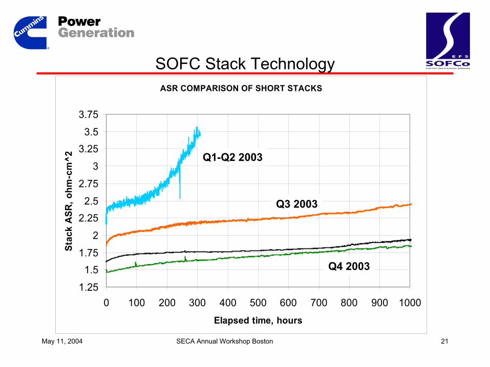
SOFC Stack TechnologyASR COMPARISON OF SHORT STACKS
1.25
1.51.75
2
2.252.5
2.75
3
3.253.5
3.75
0 100 200 300 400 500 600 700 800 900 1000
Elapsed time, hours
Stac
k A
SR, o
hm-c
m^2 Q1-Q2 2003
Q3 2003
Q4 2003
May 11, 2004 SECA Annual Workshop Boston 22
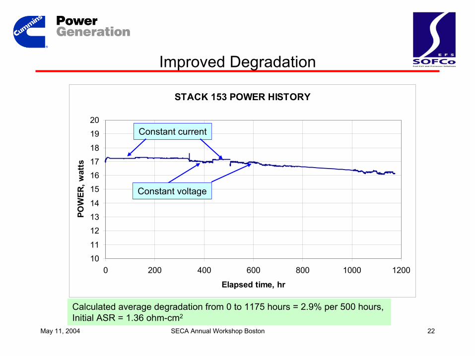
STACK 153 POWER HISTORY
1011
121314
15161718
1920
0 200 400 600 800 1000 1200
Elapsed time, hr
POW
ER, w
atts
Improved Degradation
Calculated average degradation from 0 to 1175 hours = 2.9% per 500 hours, Initial ASR = 1.36 ohm-cm2
Constant current
Constant voltage
May 11, 2004 SECA Annual Workshop Boston 23
SOFC Cell Development
• 2002 cell development outcomes– Reached performance plateau with YSZ electrolyte-
supported cells– Identified significant problem with integrity of co-fired cells
• 2003 cell development shifted to “dual path” approach – External sources for cells and cell technology
• Baseline 3YSZ post-fired cell for stack development• Improved electrolyte-supported cell using ScSZ electrolyte• Anode-supported cells
– Internal cell development focused on co-fired interconnect-supported cells
May 11, 2004 SECA Annual Workshop Boston 24
SOFC 2003 Cell Performance Progress– Baseline 3YSZ electrolyte-supported cell for stack
development• Stable, repeatable performance (ASR ~ 1.2 ohm-cm2)
– Evaluated ScSZ electrolyte-supported cells produced by SOFCo and several external sources
• ASR = 0.7 – 0.8 ohm-cm2
• Degradation exceeds target
– Evaluated anode-supported cells from external suppliers• ASR ~ 0.45 – 0.6 ohm-cm2
• Degradation exceeds target• Limited short stack testing
– Work planned for 2004• Cooperative development working with suppliers to improve cell
performance• Aggressive insertion of new cells into stack development
May 11, 2004 SECA Annual Workshop Boston 25
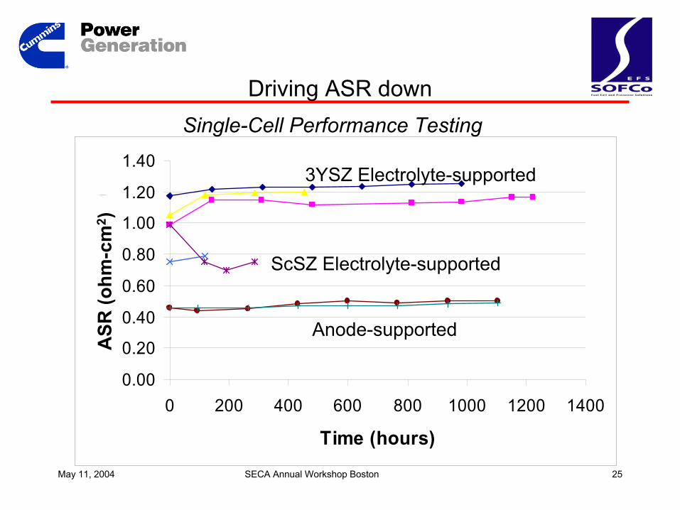
Driving ASR downSingle-Cell Performance Testing
0.00
0.20
0.40
0.60
0.80
1.00
1.20
1.40
0 200 400 600 800 1000 1200 1400
Time (hours)
ASR
(ohm
-cm
^2)
ASR
(ohm
-cm
2 )
Anode-supported
3YSZ Electrolyte-supported
ScSZ Electrolyte-supported
May 11, 2004 SECA Annual Workshop Boston 26
Manufacturing Status - BackgroundInterconnects• Manufacturing processes established
– Production moved to new facility in 2003– Over 450 interconnects produced YTD in 2004
• In-house prototyping demonstrated for 10 and 15-cm interconnects
Cells• Developing commercial sources
– 2 established– 1 under development
• SOFCo development work for improved performance– PNNL– NASA Glenn
May 11, 2004 SECA Annual Workshop Boston 27
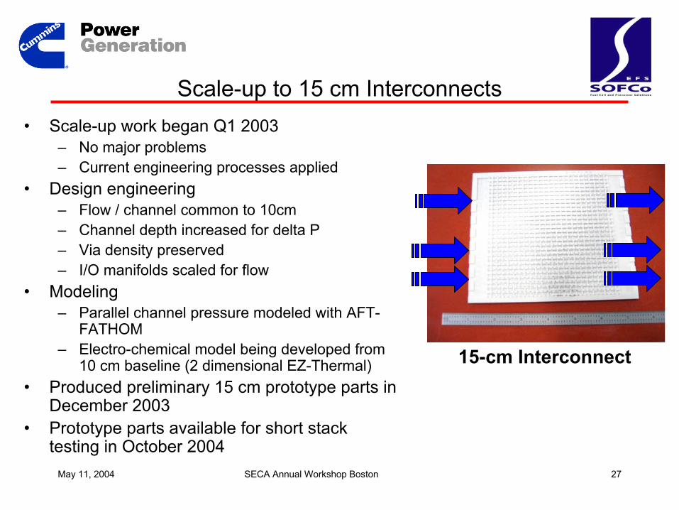
Scale-up to 15 cm Interconnects• Scale-up work began Q1 2003
– No major problems– Current engineering processes applied
• Design engineering– Flow / channel common to 10cm– Channel depth increased for delta P– Via density preserved– I/O manifolds scaled for flow
• Modeling– Parallel channel pressure modeled with AFT-
FATHOM– Electro-chemical model being developed from
10 cm baseline (2 dimensional EZ-Thermal)• Produced preliminary 15 cm prototype parts in
December 2003• Prototype parts available for short stack
testing in October 2004
15-cm Interconnect
May 11, 2004 SECA Annual Workshop Boston 28
SOFC Stack Development - Summary• Stack Scale-up
– Successful scale-up to tall stack for C1– On track with 70-cell PCU for C2 (mid 2005)
• Performance and Cost– Significant reduction in non-cell contributions to stack ASR
and degradation– Stack performance largely driven by cells– Dual path approach to evaluating anode-supported cells
and advanced ScSZ electrolyte-supported cells– On track to meet Phase 1 performance targets– Achieving cost target = meeting performance targets +
implementing low-cost materials
May 11, 2004 SECA Annual Workshop Boston 29
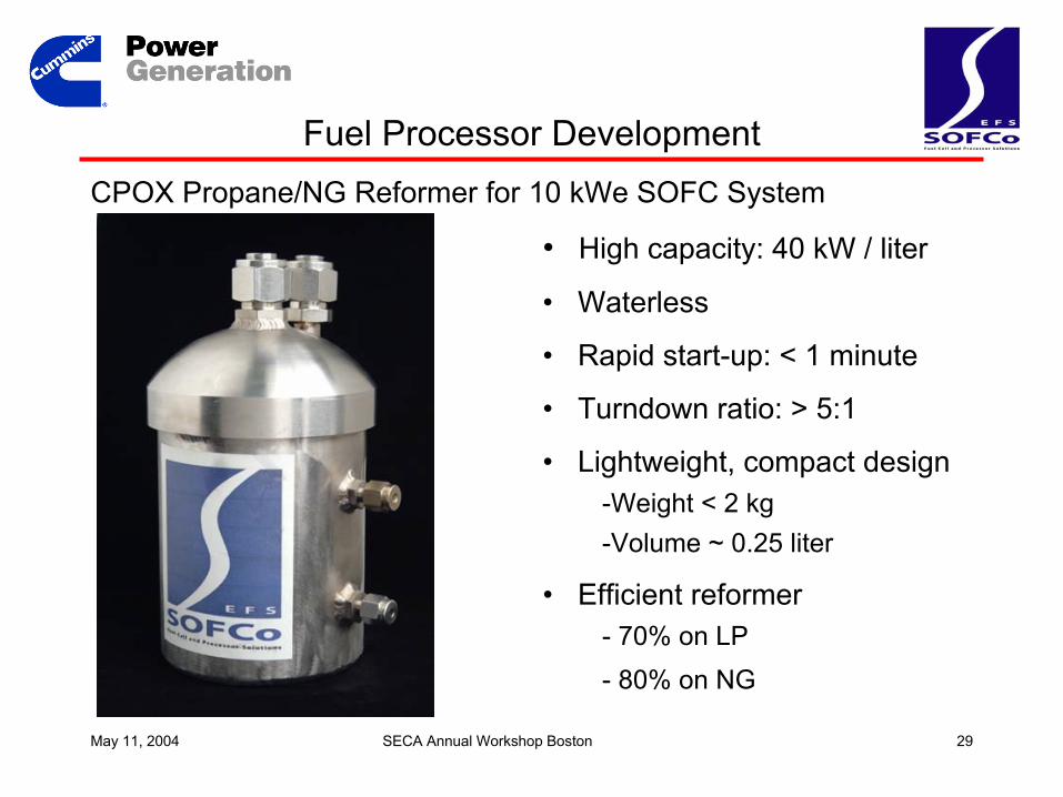
Fuel Processor DevelopmentCPOX Propane/NG Reformer for 10 kWe SOFC System
• High capacity: 40 kW / liter
• Waterless
• Rapid start-up: < 1 minute
• Turndown ratio: > 5:1
• Lightweight, compact design-Weight < 2 kg-Volume ~ 0.25 liter
• Efficient reformer- 70% on LP - 80% on NG
May 11, 2004 SECA Annual Workshop Boston 30
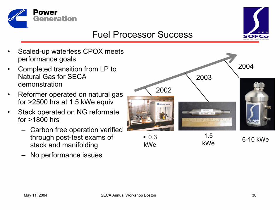
Fuel Processor Success
2002
20042003
6-10 kWe1.5 kWe
< 0.3 kWe
• Scaled-up waterless CPOX meets performance goals
• Completed transition from LP to Natural Gas for SECA demonstration
• Reformer operated on natural gas for >2500 hrs at 1.5 kWe equiv
• Stack operated on NG reformate for >1800 hrs– Carbon free operation verified
through post-test exams of stack and manifolding
– No performance issues
May 11, 2004 SECA Annual Workshop Boston 31
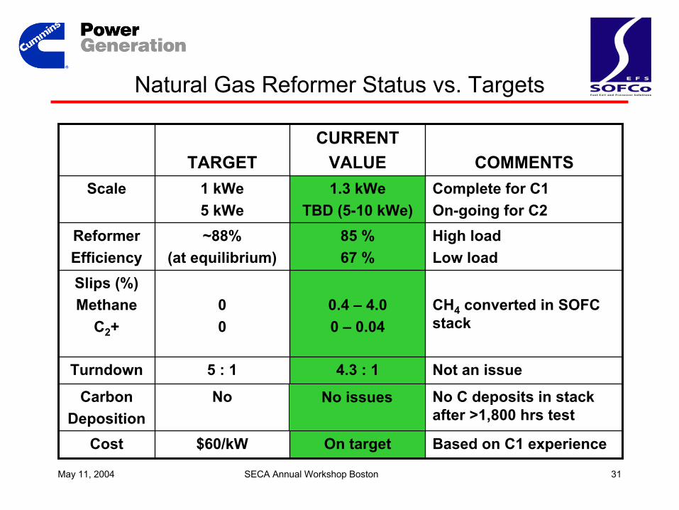
Natural Gas Reformer Status vs. Targets
Complete for C1On-going for C2
1.3 kWeTBD (5-10 kWe)
1 kWe5 kWe
Scale
Based on C1 experienceOn target$60/kWCost
No C deposits in stack after >1,800 hrs test
NoCarbonDeposition
Not an issue4.3 : 15 : 1Turndown
CH4 converted in SOFC stack
0.4 – 4.00 – 0.04
00
Slips (%)Methane
C2+
High loadLow load
85 %67 %
~88%(at equilibrium)
ReformerEfficiency
COMMENTSCURRENT
VALUETARGET
No issues
May 11, 2004 SECA Annual Workshop Boston 32
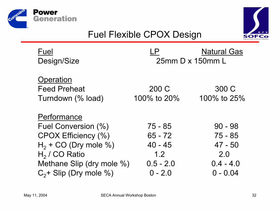
Fuel LP Natural GasDesign/Size 25mm D x 150mm L
OperationFeed Preheat 200 C 300 C Turndown (% load) 100% to 20% 100% to 25%
PerformanceFuel Conversion (%) 75 - 85 90 - 98CPOX Efficiency (%) 65 - 72 75 - 85H2 + CO (Dry mole %) 40 - 45 47 - 50H2 / CO Ratio 1.2 2.0Methane Slip (dry mole %) 0.5 - 2.0 0.4 - 4.0C2+ Slip (Dry mole %) 0 - 2.0 0 - 0.04
Fuel Flexible CPOX Design
May 11, 2004 SECA Annual Workshop Boston 33
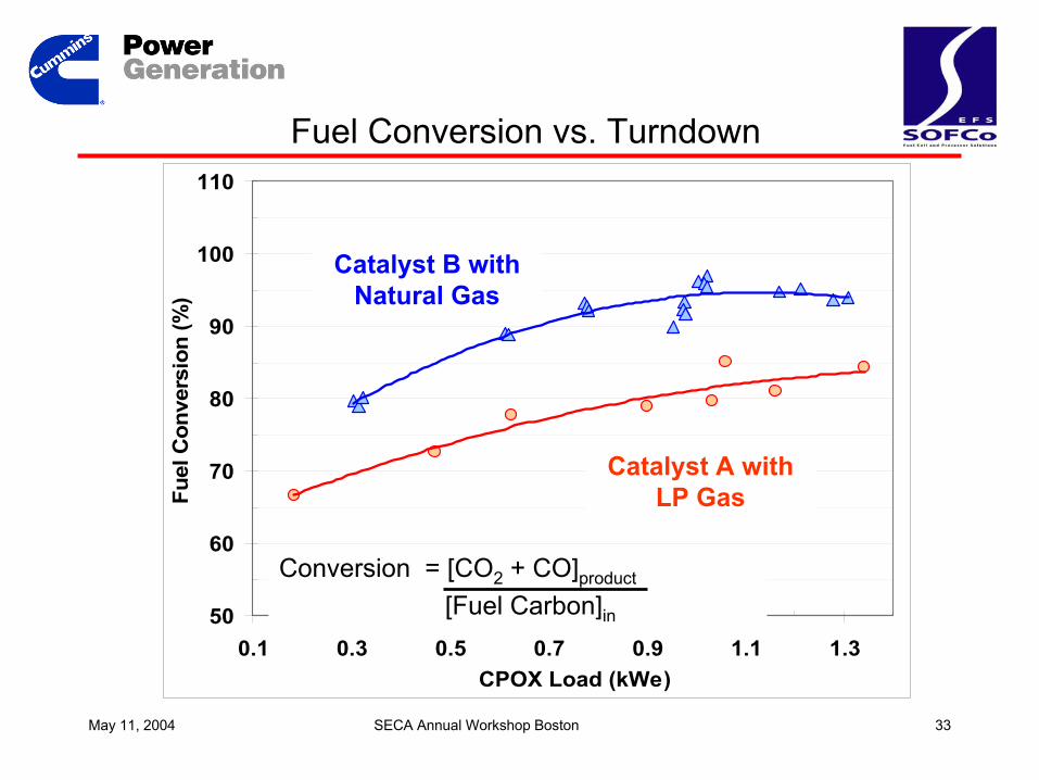
Fuel Conversion vs. Turndown
50
60
70
80
90
100
110
0.1 0.3 0.5 0.7 0.9 1.1 1.3CPOX Load (kWe)
Fuel
Con
vers
ion
(%)
Cat B [NG]
Cat A [LP]Catalyst A with LP Gas
Catalyst B with Natural Gas
Catalyst A with LP Gas
Conversion = [CO2 + CO]product
[Fuel Carbon]in
May 11, 2004 SECA Annual Workshop Boston 34
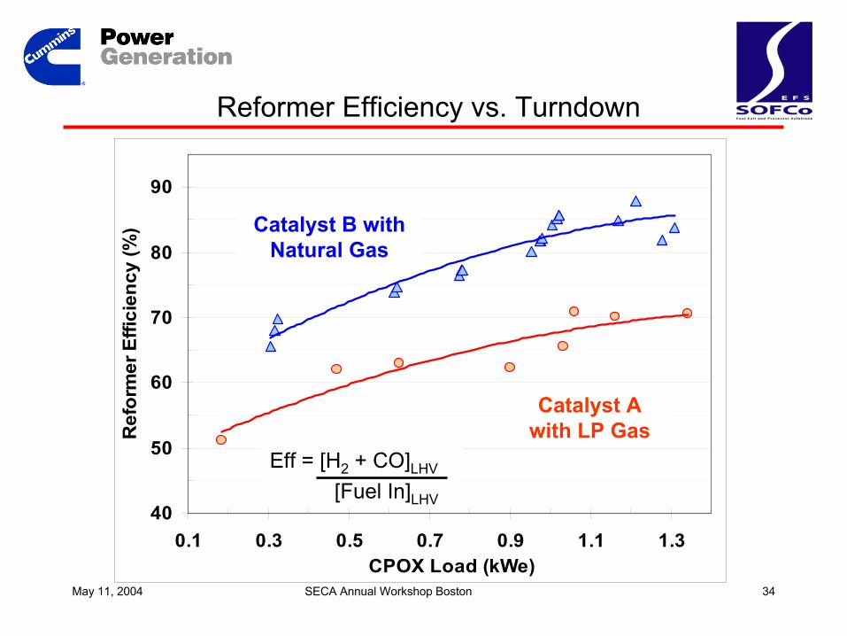
40
50
60
70
80
90
0.1 0.3 0.5 0.7 0.9 1.1 1.3CPOX Load (kWe)
Ref
orm
er E
ffici
ency
(%) Cat B [NG]
Cat A [LP]
Catalyst B with Natural Gas
Catalyst A with LP Gas
Reformer Efficiency vs. Turndown
Eff = [H2 + CO]LHV
[Fuel In]LHV
May 11, 2004 SECA Annual Workshop Boston 35
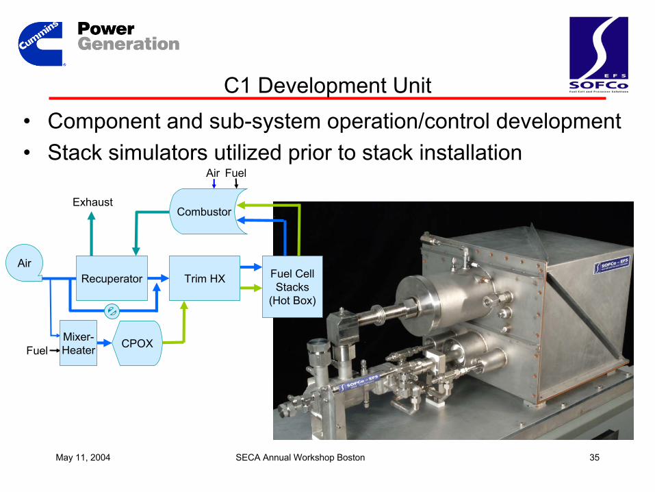
C1 Development Unit
Hot Box
Combustor
Recuperator
Reformer (CPOX)
Trim HX
CPOX
Fuel CellStacks
(Hot Box)
Exhaust
Fuel
Fuel
Air
Combustor
Recuperator
Air
Mixer-Heater
Trim HX
• Component and sub-system operation/control development• Stack simulators utilized prior to stack installation
May 11, 2004 SECA Annual Workshop Boston 36
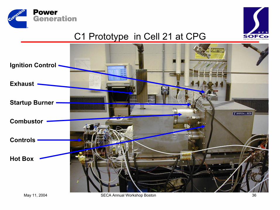
C1 Prototype in Cell 21 at CPG
Ignition Control
Exhaust
Startup Burner
Combustor
Controls
Hot Box
May 11, 2004 SECA Annual Workshop Boston 37
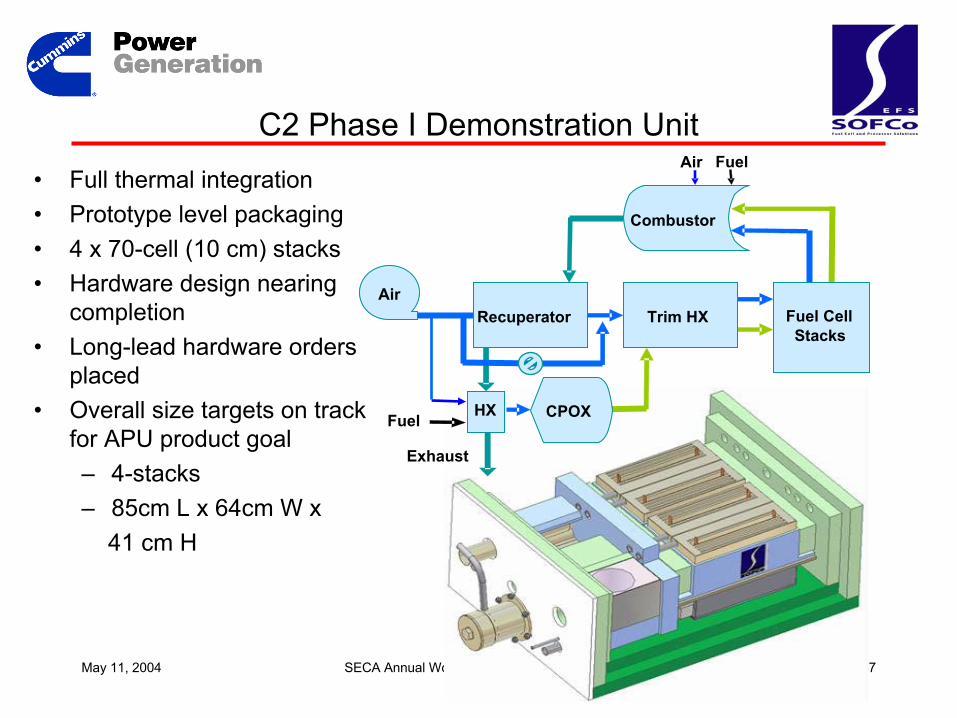
C2 Phase I Demonstration Unit• Full thermal integration• Prototype level packaging• 4 x 70-cell (10 cm) stacks• Hardware design nearing
completion• Long-lead hardware orders
placed• Overall size targets on track
for APU product goal– 4-stacks– 85cm L x 64cm W x
41 cm H
CPOX
Fuel CellStacks
Exhaust
Fuel
Fuel
Air
Combustor
Recuperator
Air
HX
Trim HX
May 11, 2004 SECA Annual Workshop Boston 38
Balance of Plant
• Balance of Plant concept translated into functional C1 systems– Components selected to meet the functional requirements
– Functional checks completed on • Anode air and fuel supply systems
• Cathode air supply and bypass subsystems
– First operational testing of the C1 system with simulated stacks conducted 12/17/03
– Test cell up-fit for fuel cell specific instrumentation, safety, and controls completed
• C1 analysis and experience will be factored into C2
May 11, 2004 SECA Annual Workshop Boston 39
SOFC Controls and Power Electronics
• Thermal and fluid management– Control stack average temperature.– Control temperature gradient across the stack.– Control flows to match current demand and fuel utilization
• Load management– Buffer required load power and fuel cell dynamics.– Ramped stack loading– Managed energy storage
Purpose of controls and power electronics
May 11, 2004 SECA Annual Workshop Boston 40
BOP controls hardware architecture
• Controls hardware – Designed Q1-Q2 2003
– Implemented Q3-Q4 2003
• Controls sited on CPG production master control unit (MCU) for development purposes– Adapts existing software platform and tools.
• Distributed architecture based on a CAN serial bus.– Provides flexibility in choice of actuators.
– Simplified interface to power electronic controls.
May 11, 2004 SECA Annual Workshop Boston 41
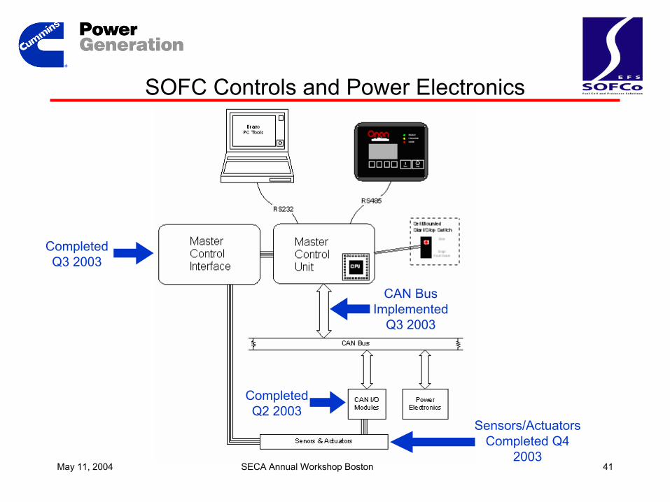
SOFC Controls and Power Electronics
Completed Q3 2003
Completed Q2 2003
CAN Bus Implemented
Q3 2003
Sensors/Actuators Completed Q4
2003
May 11, 2004 SECA Annual Workshop Boston 42
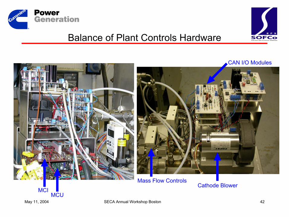
Balance of Plant Controls Hardware
Cathode BlowerMass Flow Controls
CAN I/O Modules
MCUMCI
May 11, 2004 SECA Annual Workshop Boston 43
SOFC Controls and Power Electronics
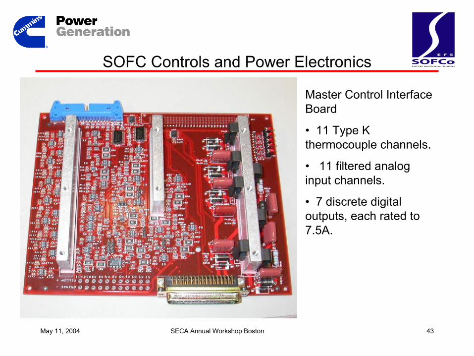
Master Control Interface Board
• 11 Type K thermocouple channels.
• 11 filtered analog input channels.
• 7 discrete digital outputs, each rated to 7.5A.
May 11, 2004 SECA Annual Workshop Boston 44
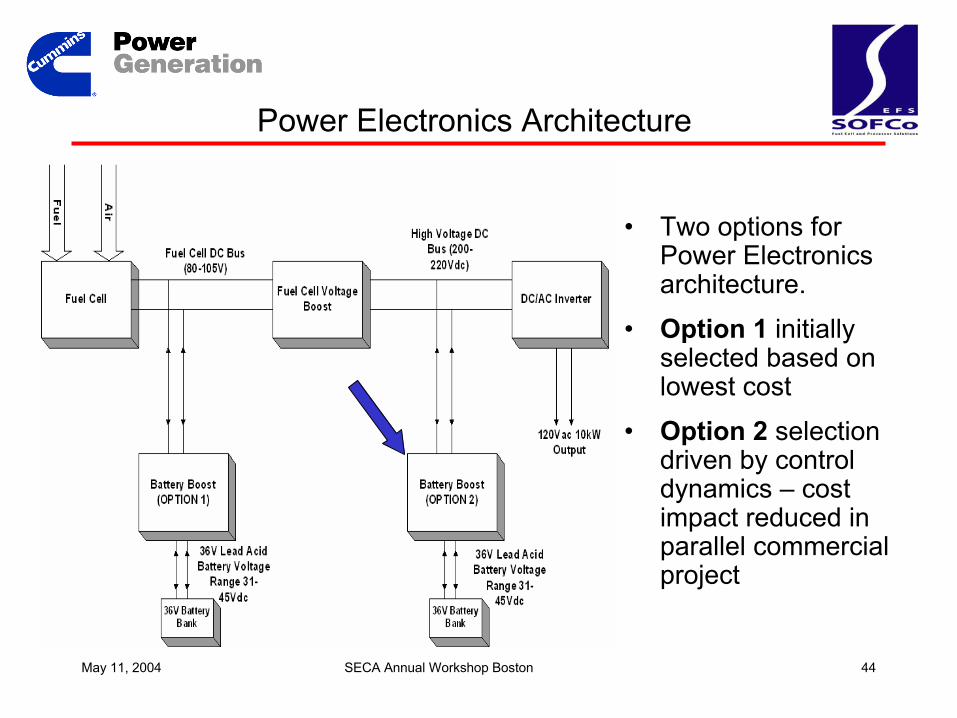
• Two options for Power Electronics architecture.
• Option 1 initially selected based on lowest cost
• Option 2 selection driven by control dynamics – cost impact reduced in parallel commercial project
Power Electronics Architecture
May 11, 2004 SECA Annual Workshop Boston 45
SECA Program Progress -- Summary
– Matrixed development of all-ceramic cells and interconnects demonstrating progress consistent with Phase 1 targets
– First generation prototype on schedule consistent with product goals
– Parallel paths in place to evolve systems and components
– Demonstrated performance of CPOX reformer
– BOP, controls, and power electronics available to support system development
May 11, 2004 SECA Annual Workshop Boston 46
Acknowledgements
Glenn Research Center
May 11, 2004 SECA Annual Workshop Boston 47
SECA ProgramCummins Power Generation
10kWe SOFC Power System Commercialization ProgramBoston, MA
May 11, 2004
This presentation was prepared with the support of the U.S. Department of Energy, under Award no. DE-FC26-01NT41244.
However, any opinions, findings, conclusions, or recommendationsexpressed herein are those of the author(s) and do not necessarily
reflect the views of the DOE.
SECA Annual Workshop