Embed Size (px)
Citation preview
G. Zimmerman SolarFlare Communications 1
Transmission Proposal for Transmission Proposal for 10GBASE10GBASE--T T
G. Zimmerman, SolarFlare

G. Zimmerman SolarFlare Communications 2
SupportersSupporters• Rick Rabinovich, Spirent Communications• Dan Dove, HP• Joel Goergen, Force 10 Networks• Chris DiMinico, MC Communications• Mike Bennett, Lawrence Berkeley Labs• Michael Laudon, Force 10 Networks

G. Zimmerman SolarFlare Communications 3
OutlineOutline• Overview• Baud Rate: Info. Bits/Baud• Equalization• FEC/Trellis Coding• Launch Power Backoff
G. Zimmerman SolarFlare Communications 4
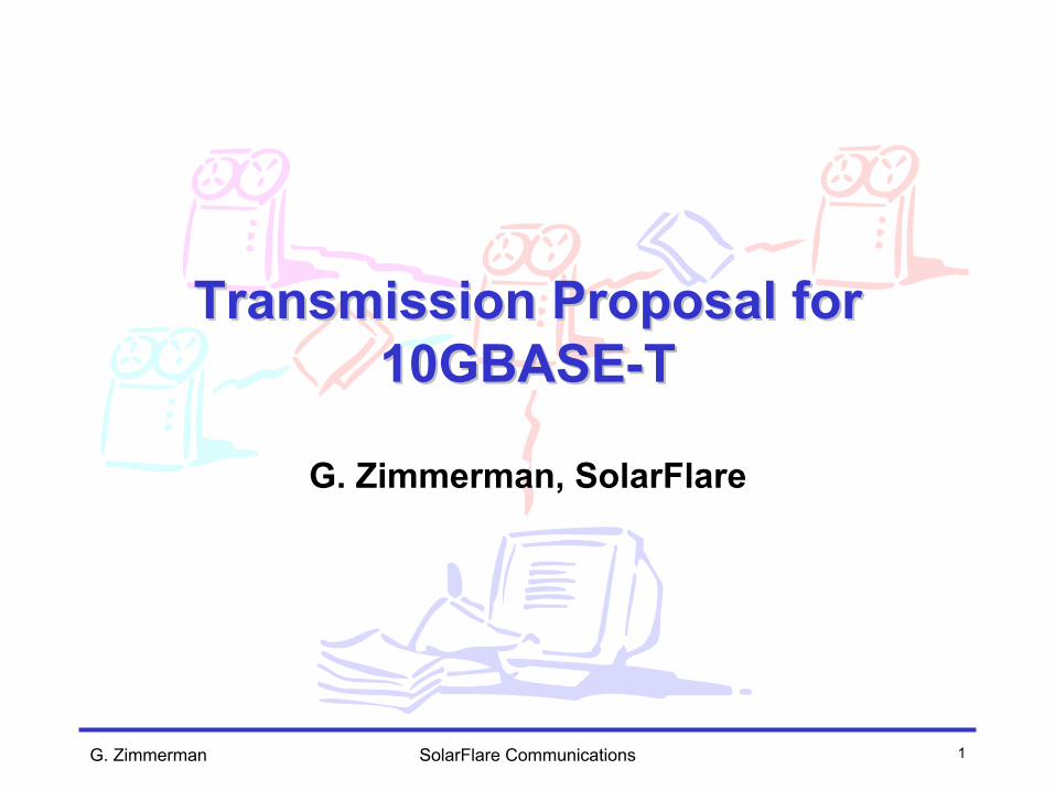
Overview: Key Choices to MakeOverview: Key Choices to Make• Line coding
– Starts with baud rate (bandwidth)– Exact # levels of PAM tied to FEC choice– May requires overhead for MAC control symbols
• Depends on coding
• FEC choice & partition– Includes both line coding & partition
• Launch voltage– Power consumption/Noise immunity tradeoff– EMI constraint– Power backoff for short lines

G. Zimmerman SolarFlare Communications 5
Overview: Elements ConsideredOverview: Elements Considered• Channel models
– 55m Class E Objective:• Cabling ad hoc IL, NEXT, FEXT & RL models
(http://www.ieee802.org/3/10GBT/public/material/10GBASE-T_Cat6_Model.zip)
• Class E ad hoc ANEXT model, Class E ISO proposal (15 dB/decade)
– 100m Class E+ Objective:• Class E ad hoc IL, NEXT, FEXT & RL models• Proposals from TR42, ISO, and 3rd parties
• EMI models– EMI radiative transfer function derived from measurements
presented to IEEE 10GBASE-T Study Group• Component effects
– Magnetics bandwidths– Timing recovery effects
• Info bits/baud – determines baud rate– Based on Optimal DFE signal processing

G. Zimmerman SolarFlare Communications 6
Baud Rate: Info bits/baud (/pair)Baud Rate: Info bits/baud (/pair)• Determines necessary & used bandwidth
– Performance, Power & EMI Constrained• DFE systems generally have a unique optimum• Performance vs. baud rate on DFE channels is
not identical to AWGN channels– Rate loss is channel dependent
• (Rate loss in DFEs under “pinch off” conditions: ref. T1E1.4/97-241)
• Optimal DFE Margin (Salz) normalized to bits/baud:– Uncoded Margin = -10*log10(Salz_MSE)-
Capacity_SNR+12.27dB– Capacity SNR = 10*log10(2^(2*bits/baud/pair) – 1) dB

G. Zimmerman SolarFlare Communications 7
Baud Rate: 55m Class E Ad Hoc ModelBaud Rate: 55m Class E Ad Hoc Model• Very shallow optimum• ANEXT Model exhibits <10dB/decade ANEXT
slope
2 2.2 2.4 2.6 2.8 3 3.2 3.4 3.6 3.8 4-4
-3.5
-3
-2.5
-2
-1.5
-1
-0.5
0
0.5Uncoded DFEMARGIN
0 100 200 300 400 500 600-200
-180
-160
-140
-120
-100
-80
-60
signal outrem nextrem alien nextrem fextrem echorem awgn
Uncoded DFE Margin vs. bits/baud/pairReceived Residual PSDs
dBm
/Hz
Unc
oded
Mar
gin
(dB
)
Info bits/baud/pair

G. Zimmerman SolarFlare Communications 8
Baud Rate: 55m Class E with 15dB / Baud Rate: 55m Class E with 15dB / decade ANEXT modeldecade ANEXT model• Optimum shifts towards 3 bits/baud & steepens• ANEXT Model based on presentations
– Conforms with data(hayes_1_0303.pdf, abughalazeh_1_0903.pdf)– ANEXT Loss = 47-15log10(f/100) + 2.5 dB (limit line adj)
2 2.2 2.4 2.6 2.8 3 3.2 3.4 3.6 3.8 4-2.5
-2
-1.5
-1
-0.5
0
0.5Uncoded DFEMARGIN
0 100 200 300 400 500 600-200
-180
-160
-140
-120
-100
-80
signal outrem nextrem alien nextrem fextrem echorem awgn
Uncoded DFE Margin vs. bits/baud/pairReceived Residual PSDs
dBm
/Hz
Unc
oded
Mar
gin
(dB
)
Info bits/baud/pair

G. Zimmerman SolarFlare Communications 9
Baud Rate: 100m Class E+ ExampleBaud Rate: 100m Class E+ Example• DFE Margin vs. info bits/baud strongly favors
lower baud rates– ANEXT Loss = 60-15*log10(f/100) + 2.5dB (limit line adj.)
2 2.2 2.4 2.6 2.8 3 3.2 3.4 3.6 3.8 4-4
-3.5
-3
-2.5
-2
-1.5
-1Uncoded DFEMARGIN
0 100 200 300 400 500 600-200
-180
-160
-140
-120
-100
-80
signal outrem nextrem alien nextrem fextrem echorem awgn
Uncoded DFE Margin vs. bits/baud/pairReceived Residual PSDs
dBm
/Hz
Unc
oded
Mar
gin
(dB
)
Info bits/baud/pair
G. Zimmerman SolarFlare Communications 10
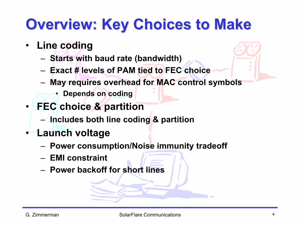
Baud Rate: EMIBaud Rate: EMI• Used Field Radiated EMI measurements to
estimate transmit PSD within FCC Class A– Issues emerge above 500 MHz
Transmit PSD with 3 dB Margin to FCC Class A EMI(from measured emissions)
-90.00
-85.00
-80.00
-75.00
-70.00
-65.00
-60.00
-55.00
-50.00
0.00 100.00 200.00 300.00 400.00 500.00 600.00 700.00 800.00 900.00 1000.00
Frequency (MHz)
Tran
smit
PSD
(dB
m/H
z)
ref: cohen_1_0903.pdf

G. Zimmerman SolarFlare Communications 11
Other ComponentsOther Components• Magnetics performance falls off beyond 500 MHz
– Adversely effects noise susceptibility & EMI in addition to received SNR
• Timing jitter degrades SNR as baud rate increases (10*log10(fb1/fb2) relative loss in ADC quant noise PSD)
ref: dihn_1_0104.pdf
G. Zimmerman SolarFlare Communications 12
Baud Rate: ConclusionsBaud Rate: Conclusions• Choice of info bits/baud (baud rate) is a function
of tradeoffs in:– Long-line Performance– ANEXT Robustness– Meeting EMI– Other component effects (e.g., Magnetics, timing)
• 3 bits/baud/pair is within 1 dB of optimum point for DFE SNR for all cases, and closer on hard cases
• 3 bits/baud/pair allows transmit PSD to roll off before 500 MHz– Meets EMI, aligns with magnetics rolloff

G. Zimmerman SolarFlare Communications 13
Equalization: TomlinsonEqualization: Tomlinson--HarashimaHarashima• Alleviates DFE error propagation in coded systems
– Cost is large amplitude “dither” element added to signal• Transmit power penalty is small for large # PAM levels
– Problems:• Dither couples through NEXT, FEXT & Echo paths• High PAR & extra dynamic range increases complexity• Incompatible with shaping gain• Requires tight circuit timing loop for feedback filter
TH Precoded Channel Equalizer Block Diagram
HffeHtxp
TransmitPrecoder Filter
Hchan
Wireline Channel Feed-ForwardEqualizer
Hdfe
TH Precoder
+/- L(PAM)
+/- 2LDither
modL

G. Zimmerman SolarFlare Communications 14
Equalization: Equalization: PrecodedPrecoded DFEDFE• Adaptive Linear precoding can shape DFE
response to minimize error propagation– Small transmit power penalty for preemphasis
• 10GBASE-T not generally transmit power limited– Can be combined with other transmit filtering– Can be combined with constellation shaping gain– Feedforward structures minimize circuit timing issues
Hdfe
HffeHtxp
TransmitPrecoder Filter
Hchan
WirelineChannel
Feed-ForwardEqualizer
Decision Feedback Equalizer
DFE-based Channel Equalizer Block Diagram

G. Zimmerman SolarFlare Communications 15
20 21 22 23 24 25 26 27 28 2910
-6
10-5
10-4
10-3
10-2
10-1
100
Simulated Symbol Error Rates for Uncoded PAM10
Signal-to-Noise Ratio (dB)
Sym
bol E
rror R
ate
Linear Tx PrecodingDFE with Correct DecisionsDFETheory
Equalization: Equalization: PrecodedPrecoded DFEDFE
Transmit PSD and EMI with Precoded Filter
• Precoder coefficients trained at startup to adapt to varying line lengths
• Max DFE feedback coefficient can be constrained < .25
• DFE can be shaped to avoid catastrophic error propagation
0 2 4 6 8 10
x 108
0
10
20
30
40
50
60
70
801 00 mete r c h a nne l5 0 m e te r spa n Ca t 5eF CC Cla s s A limitF CC Cla s s B limit

G. Zimmerman SolarFlare Communications 16
FEC/Trellis coding: LatencyFEC/Trellis coding: Latency• Applications show need for lower latency codes
– Distributed computing, clustering require capability for low latency operation
• Includes propagation, code and signal processing latency• Long lines mask PHY latency (propagation delay)
• Generic Ethernet places no hard requirement on 10GBT– Legacy of the fact that 802.3ae was engineered for multi-km
links (light time > 5 usec)• Previous Ethernet has not stated latency as a requirement
• High latency codes PERMANENTLY bar technical innovation from achieving low latency operation
• Additional coding gain can be achieved by layering an outer code, if necessary, on long lines without impairing minimum PHY latency on shorter lines

G. Zimmerman SolarFlare Communications 17
Code Proposal: 4DCode Proposal: 4D--4W4W--Trellis CodeTrellis Code• 4D (across pairs) PAM-10 with 4-way time-interleave
and constellation shaping• Advantages
– Meets 3 bits/baud information rate• Encodes control symbols into modulation, avoiding rate loss
– Provides for minimal latency operation (<< .25usec)– Provides for constellation shaping gain (0.64 dB)– 4-way interleave allows lower-rate decoder clocking– Interleave mitigates noise correlation effects– Interleave mitigates error propagation effects– Low complexity hardware encoding & decoding– Allows concatenation for layering block FEC if desired for
improved impulsive noise or long line performance

G. Zimmerman SolarFlare Communications 18
Line Code Proposal: 4DLine Code Proposal: 4D--4W4W--PAM10PAM10• 8st 4D Ungerboeck code used in 1000BASE-T
– 2^13 possible encoded symbols– 10,000 constellation points– Remaining 1808 points can be used for control symbols
• 4 Way time interleaving, code is 4D across pairs• Balanced constellation
– No polarity scrambler required• Shaped constellation (0.64 dB shaping gain)
-9 -7 -5 -3 -1 +1 +3 +5 +7 +9 512 896 896 896 896 896 896 896 896 512
Table 1: 1D PAM Level Rate of Occurrence in the 4D Mapping (8192 points)

G. Zimmerman SolarFlare Communications 19
4D4D--4Way PAM4Way PAM--10 Code Performance10 Code Performance
Slicer Input SNR (dB)
19 20 21 22 23 24 25 26 2710
-14
10-12
10-10
10-8
10-6
10-4
10-2
100
Coded PAM10 simulation SERCoded PAM10 Theory SERCoded PAM10 Theory BER
26.2 dB

G. Zimmerman SolarFlare Communications 20
Launch Power TradeoffsLaunch Power Tradeoffs• Launch power < 10 dBm due to EMI constraints• Long line launch power > 6 dBm due to
1000BASE-T ANEXT constraints• Negotiated launch power backoff
– Widely used in deployed DSL standards to mitigate asymmetric link near/far problem
– Lines less than 50m– Negotiated at Startup, based on SNR and/or attenuation– Minimum backoffs to be specified in the standard

G. Zimmerman SolarFlare Communications 21
Baud Rate ProposalBaud Rate Proposal• Motion #1: That 10GBASE-T baseline baud rates
consistent with 3 information bits/baud/pair

G. Zimmerman SolarFlare Communications 22
Coding proposalCoding proposal• Motion #2: That 10GBASE-T adopt as a 3
bits/baud/pair 4D-4Way PAM-10 code with integrated control symbols

G. Zimmerman SolarFlare Communications 23
Power Power BackoffBackoff ProposalProposal• Motion #3: That 10GBASE-T adopt a power-
backoff mechanism adapted on startup for use on shorter lines – levels and metrics TBD.

G. Zimmerman SolarFlare Communications 24
Backup SlidesBackup Slides

G. Zimmerman SolarFlare Communications 25
Relation of Rate Loss in DFE systems Relation of Rate Loss in DFE systems under pinchunder pinch--offoff• Optimum DFE Result:
• When f_SNR(f) is small for f>fbaud, increasing the baud rate does not change the value of the integral as in an AWGN channel
∫
∫
+=
+=
B
B
dffSNRffbaud
dffSNRffbaud
dBSNR
0
0
)))(_1ln(*))1(exp(10log10
)))(_1ln(1exp(10log*10)(

G. Zimmerman SolarFlare Communications 26
ANEXT Robustness: Variability of Required Channel Capacity with ANEXT Robustness: Variability of Required Channel Capacity with Constant SNR ConstraintConstant SNR Constraint
• ANEXT = Y + 15*log10(f/100), where Y is adjusted to produce target receive SNR
• Channel contains 4 connectors + 10 m patch cords; length adjusted with horizontal cable span only
•Target SNR includes• BER = 10e-12• 5.5 dB coding gain• 3 dB margin
• Impairments (Class E):• Echo = 55 dB• NEXT = 40 dB• FEXT = 25 dB• Noise = -150 dBm/Hz
• Transmit power = 8 dBm40 50 60 70 80 90 100
16
17
18
19
20
21
22
Channel length (meters)
Req
uire
d C
hann
el C
apac
ity (G
bps)
Required Channel Capacity vs Class E Channel Length for Different PAM Codes
2 bits/symbol: 23 dB Rcv SNR3 bits/symbol: 29 dB Rcv SNR4 bits/symbol: 35 dB Rcv SNR
ref: TR42.7-04-02-012

G. Zimmerman SolarFlare Communications 27
ANEXT Robustness: Value of ANEXT Coupling Constant (Y) with ANEXT Robustness: Value of ANEXT Coupling Constant (Y) with Constant SNR ConstraintConstant SNR Constraint
• ANEXT = Y + 15*log10(f/100), where Y is adjusted to produce target receive SNR
• Channel contains 4 connectors + 10 m patch cords; length adjusted with horizontal cable span only
• Target SNR includes• BER = 10e-12• 5.5 dB coding gain• 3 dB margin
• Impairments:• Echo = 55 dB• NEXT = 40 dB• FEXT = 25 dB• Noise = -150 dBm/Hz
• Transmit power = 8 dBm
40 50 60 70 80 90 10040
45
50
55
60
65
70
75
Channel length (meters)
AN
EX
T C
onst
ant
Value of ANEXT Constant vs Class E Channel Length for Different PAM Codes
2 bits/symbol: 23 dB Rcv SNR3 bits/symbol: 29 dB Rcv SNR4 bits/symbol: 35 dB Rcv SNR
ref: TR42.7-04-02-012

G. Zimmerman SolarFlare Communications 28
Error Propagation PerformanceError Propagation Performance
20 21 22 23 24 25 26 2710-8
10-7
10-6
10-5
10-4
10-3
10-2
10-1
Error Prop Reduction 4D-Pairs 8st Coded PAM10, ERPX
EQ Output SNR (dB), residual ISI compensated
PAM10 DFE 4D-SERPAM10 DFE w/ perf FB 4D-SERPAM10 1way Vit 4D-SERPAM10 1way Vit w/ perf FB 4D-SERPAM10 4way Vit 4D-SERPAM10 4way Vit w/ perf FB 4D-SERPAM8 AWGN 4pr SERPAM10 AWGN 4D8st Vit 4pr-SER
Slicer SNR (dB)
Sym
bol E
rror
Rat
e

G. Zimmerman SolarFlare Communications 29
Coding Description: EncoderCoding Description: Encoder
TX S
CR
AM
BLE
R
TXDn[0:11]
4D P
AM
10 MA
PP
ING
D D Dcsn[1] csn[1]
Sdn[0]
Sdn[1]
Sdn[2]
Sdn[3]
Sdn[4]
Sdn[5]
Sdn[6]
Sdn[7]
Sdn[8]
Sdn[9]
Sdn[10]
Sdn[11]
Sdn[12]
csn[0]
Select SubsetSelect P
oint in Subset
Scn[0:11]
TransmitData
FromLFSR
TXA
TXB
TXC
TXD

G. Zimmerman SolarFlare Communications 30
Coding Description: Trellis DiagramCoding Description: Trellis Diagram
010
011
100
101
110
111
000
001
010
011
100
101
110
111
000
001
D0 D2 D4 D6
D1 D3 D5 D7
D2 D0 D6 D4
D3 D1 D7 D5
D4 D6 D0 D2
D5 D7 D1 D3
D6 D4 D2 D0
D7 D5 D3 D1
D0 D2 D4 D6
D1 D3 D5 D7
D2 D0 D6 D4
D3 D1 D7 D5
D4 D6 D0 D2
D5 D7 D1 D3
D6 D4 D2 D0
D7 D5 D3 D1
ConvolutionalEncoder Bits attime n
ConvolutionalEncoder Bits at
time n+1
Subset for eachof 4 branchesleaving state
Subset for eachof 4 branchesentering state

G. Zimmerman SolarFlare Communications 31
2 2.2 2.4 2.6 2.8 3 3.2 3.4 3.6 3.8 4-4
-3.5
-3
-2.5
-2
-1.5Uncoded DFEMARGIN
Baud Rate: 55m Class E with split Baud Rate: 55m Class E with split ANEXT modelANEXT model• Optimum shifts towards 3 bits/baud & steepens• Class E IL
– ANEXT Loss = 49-X*log10(f/100) (X=15, f>100, X=10, f<=100)
Uncoded DFE Margin vs. bits/baud/pairReceived Residual PSDs
dBm
/Hz
Unc
oded
Mar
gin
(dB
)
Info bits/baud/pair0 100 200 300 400 500 600 700
-200
-180
-160
-140
-120
-100
-80
signal outrem nextrem alien nextrem fextrem echorem awgn

G. Zimmerman SolarFlare Communications 32
2 2.2 2.4 2.6 2.8 3 3.2 3.4 3.6 3.8 4-4.5
-4
-3.5
-3
-2.5
-2
-1.5
-1
Uncoded DFEMARGIN
Baud Rate: 100m Class E+ ExampleBaud Rate: 100m Class E+ Example• DFE Margin vs. info bits/baud strongly favors
lower baud rates (Class E IL)– ANEXT Loss = 64-X*log10(f/100) (X=15, f>100, X=10,
f<=100)Uncoded DFE Margin vs. bits/baud/pairReceived Residual PSDs
dBm
/Hz
Unc
oded
Mar
gin
(dB
)
Info bits/baud/pair0 100 200 300 400 500 600
-200
-180
-160
-140
-120
-100
-80
signal outrem nextrem alien nextrem fextrem echorem awgn

G. Zimmerman SolarFlare Communications 33
2 2.2 2.4 2.6 2.8 3 3.2 3.4 3.6 3.8 4-4
-3.5
-3
-2.5
-2
-1.5
-1
Uncoded DFEMARGIN
Baud Rate: 100m Class E+ ExampleBaud Rate: 100m Class E+ Example• DFE Margin vs. info bits/baud strongly favors
lower baud rates (Class F IL)– ANEXT Loss = 62-X*log10(f/100) (X=15, f>100, X=10,
f<=100)Uncoded DFE Margin vs. bits/baud/pairReceived Residual PSDs
dBm
/Hz
Unc
oded
Mar
gin
(dB
)
Info bits/baud/pair0 100 200 300 400 500 600
-200
-180
-160
-140
-120
-100
-80
signal outrem nextrem alien nextrem fextrem echorem awgn