Embed Size (px)
Citation preview

Nevion Nordre Kullerød 1 3241 Sandefjord Norway Tel: +47 33 48 99 99
nevion.com
10G-TR-2-XFP-SFP
Bidir/dual optical to optical 10Gbps transponder
User manual
Rev. A

10G-TR-2-XFP-SFP Rev. A
nevion.com | 2
Nevion Support
Nevion Europe
P.O. Box 1020 3204 Sandefjord, Norway
Support phone 1: +47 33 48 99 97 Support phone 2: +47 90 60 99 99
Nevion USA
1600 Emerson Avenue Oxnard, CA 93033, USA
Toll free North America: (866) 515-0811 Outside North America: +1 (805) 247-8560
E-mail: [email protected]
See http://www.nevion.com/support/ for service hours for customer support globally.
Revision history
Current revision of this document is the uppermost in the table below.
Rev. Repl. Date Sign Change description
A - 2016-04-12 OEH Initial document

10G-TR-2-XFP-SFP Rev. A
nevion.com | 3
Contents
Revision history ........................................................................................................ 2
1 Product overview ................................................................................................... 4
2 Specifications ........................................................................................................ 5 2.1 General ......................................................................................................................... 5 2.1 SUPPORTED STANDARDS ......................................................................................... 5 2.2 OPTICAL INPUT ........................................................................................................... 5 2.3 OPTICAL OUTPUT ....................................................................................................... 5
3 Configuration ......................................................................................................... 6
4 Connections ........................................................... Error! Bookmark not defined. 4.1 Mounting the connector module ...................................................................................11
5 Operation ............................................................................................................. 12 5.1 Front panel – Status monitoring ...................................................................................12 5.2 Multicon Gyda ..............................................................................................................13
General environmental requirements for Nevion equipment .................................. 14
Product Warranty.................................................................................................... 15
Appendix A Materials declaration and recycling information .................................. 16 A.1 Materials declaration ....................................................................................................16 A.2 Recycling information ...................................................................................................16

10G-TR-2-XFP-SFP Rev. A
nevion.com | 4
1 Product overview
The 10G-TR-2-XFP-SFP receives, re-clocks and retransmit a bidirectional 10G optical signal (or two unidirectional ones). The product uses one XFP and one SFP+ for optical interfaces and thru those the 10G-TR-2-XFP-SFP supports both 850nm multimode and 13T, CWDM (18 channels) and DWDM (40 channels) single mode, enabling both wavelength and fiber type conversion. The distance relates to obtainable maximum distance given the correct type of fiber. The module is monitored and controlled over RS422 by Multicon Gyda, enabling SNMP support. The module can also be controlled thru DIP switches on the card, and 4 LEDs will indicate the status of the module.
Microcontroller
10Gbps
CWDM10Gbps
1270-1650nm
Remote control
Clock and
data recovery
10Gbps
CWDMClock and
data recovery
10Gbps
1270-1650nm
SFP+ XFP
Figure 1: Block diagram of the 10G-TR-2-XFP-SFP
The figure below shows a typical setup for adding 10G switches to an optical Flashlink network. Switches already having CWDM/DWDM wavelengths can be added to a Flashlink network, without the use of the 10G-TR, but the 10G-TR also brings the optical link into the management system of the Flashlink network.
CWDM /
DWDM
filter10G
Switch
10G
Switch
CWDM/
DWDM
filter
850/13T10G-TR-2-
XFP-SFP
C1xxx/
D15xx.xx
850/13T10G-TR-2-
XFP-SFP
C1xxx/
D15xx.xx
Figure 2: This figure shows a typical setup for wavelength conversion

10G-TR-2-XFP-SFP Rev. A
nevion.com | 5
2 Specifications
2.1 General Power +5V DC / 6W, max (worst case with 1.65W SFP+
and 3.5W XFP)
Control DIP configuration and SNMP monitoring
Temperature range 0 to +40 °C
Optical transport distance See manual for installed XFP
2.1 SUPPORTED STANDARDS 10GBASE-SR/SW/LR/LW/ER/EW/ZR/ZW 10G Ethernet,
1200-SM-LL-L 10G Fiber Channel
SONET OC-192 IR-2
SDH STM S-64.2b
SONET OC-192 IR-3
SDH STM S-64.3b
ITU-T G.709
2.2 OPTICAL INPUT Number of inputs 2
Connectors LC/UPC
Rx Sensitivity See manual for installed XFP and SFP+
Overload See manual for installed XFP and SFP+
2.3 OPTICAL OUTPUT Number of outputs 2
Connector LC/UPC
Tx optical power See manual for installed XFP and SFP+
Optical wavelengths 850 850nm
13T 1310nm
CWDM 1270-1610nm (18 channels)
DWDM 1530.33nm - 1561.42nm (40 channels)

10G-TR-2-XFP-SFP Rev. A
nevion.com | 6
3 Configuration
3.1 DIP The correct configuration can either be set with a DIP switch or with the GYDA Control System. The layout of 10G-TR-2-XFP-SFP is shown in the drawing below with the DIP switch to the upper left position.
Switch # Label Function, DIP = ON Function, DIP = OFF Comment
1 1 Laser enable Laser disable
2 2 n/a
3 3 n/a
4 4 n/a
5 5 n/a
6 6 n/a
7 7 n/a
8 OVR Override GYDA control. Configuration with DIP switch
GYDA control. Configuration with GYDA
Select configuration from GYDA
All DIP switches are off when pointing towards the release handle.
3.2 Multicon GYDA
Figure 3: Multicon GYDA System Controller settings (optional)

10G-TR-2-XFP-SFP Rev. A
nevion.com | 7
3.3 Tunable DWDM optics Tunable DWDM SFP+ or XFP modules need to be configured through Multicons debug terminal. See table below for Nevions DWDM channel plan:
Channel (#) Center frequency (THz) Wavelength (nm)
20 192.0 1561.41
21 192.1 1560.61
22 192.2 1559.79
23 192.3 1558.98
24 192.4 1558.17
25 192.5 1557.36
26 192.6 1556.55
27 192.7 1555.75
28 192.8 1554.94
29 192.9 1554.13
30 193.0 1553.33
31 193.1 1552.52
32 193.2 1551.72
33 193.3 1550.92
34 193.4 1550.12
35 193.5 1549.32
36 193.6 1548.51
37 193.7 1547.72
38 193.8 1546.92
39 193.9 1546.12
40 194.0 1545.32
41 194.1 1544.53
42 194.2 1543.73
43 194.3 1542.94
44 194.4 1542.14
45 194.5 1541.35
46 194.6 1540.56
47 194.7 1539.77
48 194.8 1538.98
49 194.9 1538.19
50 195.0 1537.40
51 195.1 1536.61
52 195.2 1535.82
53 195.3 1535.04
54 195.4 1534.25
55 195.5 1533.47
56 195.6 1532.68
57 195.7 1531.90
58 195.8 1531.12
59 195.9 1530.33
Once the correct channel number has been found in column 1, open the Multicon GYDA webpage. Find and click on the card in the frame view. The URL bar of the web browser will show the address, like so (example for frame 1, slot 3): http://192.168.1.1/#frames?card=2. See Figure 4.
10G-TR-2-XFP-SFP Rev. A
nevion.com | 8
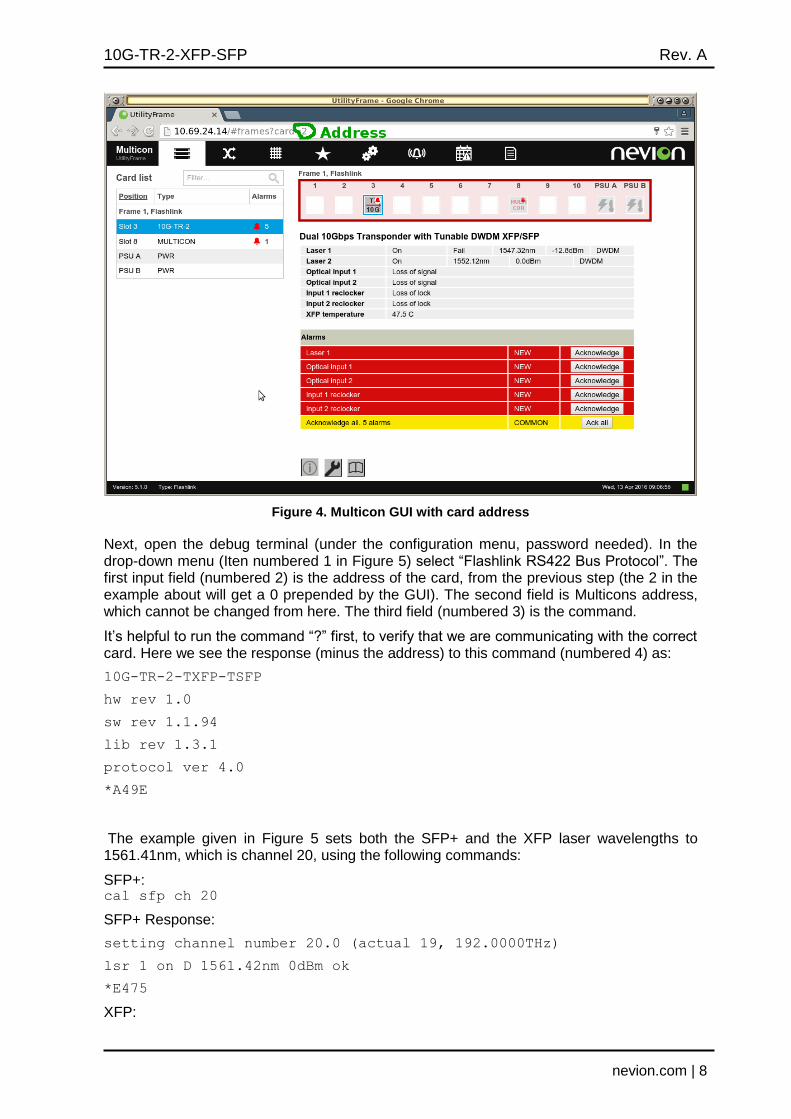
Figure 4. Multicon GUI with card address
Next, open the debug terminal (under the configuration menu, password needed). In the drop-down menu (Iten numbered 1 in Figure 5) select “Flashlink RS422 Bus Protocol”. The first input field (numbered 2) is the address of the card, from the previous step (the 2 in the example about will get a 0 prepended by the GUI). The second field is Multicons address, which cannot be changed from here. The third field (numbered 3) is the command.
It’s helpful to run the command “?” first, to verify that we are communicating with the correct card. Here we see the response (minus the address) to this command (numbered 4) as:
10G-TR-2-TXFP-TSFP
hw rev 1.0
sw rev 1.1.94
lib rev 1.3.1
protocol ver 4.0
*A49E
The example given in Figure 5 sets both the SFP+ and the XFP laser wavelengths to 1561.41nm, which is channel 20, using the following commands:
SFP+: cal sfp ch 20
SFP+ Response:
setting channel number 20.0 (actual 19, 192.0000THz)
lsr 1 on D 1561.42nm 0dBm ok
*E475
XFP:

10G-TR-2-XFP-SFP Rev. A
nevion.com | 9
cal xfp ch 20
XFP response: cal xfp ch 20
setting channel number 20.0 (actual 7, 192.0000THz)
lsr 0 on D 1561.42nm 4dBm ok
*EE45
In Figure 5 the wavelengths resulting from these operations have been circled and numbered 5 for SFP+ and 6 for XFP.
Figure 5: Tuning DWDM from debug terminal
The card can be ordered with given channels pre-configured, for convenience. Contact our sales department about this.

10G-TR-2-XFP-SFP Rev. A
nevion.com | 10
Squeeze between two fingers
4 Connections
Figure 6: Connector module for 10G-TR
Terminal Function
OPT1
XFP output
OPT2 XFP input
OPT3 SFP+ output
OPT4 SFP+ input
Figure 1. Getting LC connectors into correct position.
If any problems with entering the backplane adapter should occur, the connectors’ position should be corrected by the method shown above before a new attempt.

10G-TR-2-XFP-SFP Rev. A
nevion.com | 11
4.1 Mounting the connector module The details of how the connector module is mounted, is found in the user manual for the sub-rack frame FR-2RU-10-2.
This manual is also available from our web site:
http://www.nevion.com/.
10G-TR-2-XFP-SFP Rev. A
nevion.com | 12
5 Operation
The status of the module can be monitored in two ways.
1. Multicon GYDA System Controller (optional).
2. LED’s at the front of the sub-rack.
The LED’s are mounted on the module itself, whereas the GYDA System Controller is a separate module giving detailed information on the card status.
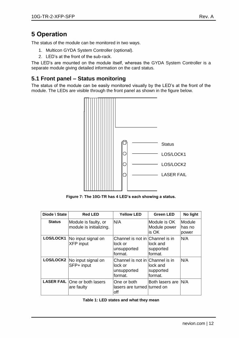
5.1 Front panel – Status monitoring The status of the module can be easily monitored visually by the LED’s at the front of the module. The LEDs are visible through the front panel as shown in the figure below.
Figure 7: The 10G-TR has 4 LED’s each showing a status.
Diode \ State Red LED Yellow LED Green LED No light
Status Module is faulty, or module is initializing.
N/A Module is OK Module power is OK
Module has no power
LOS/LOCK1 No input signal on XFP input
Channel is not in lock or unsupported format.
Channel is in lock and supported format.
N/A
LOS/LOCK2 No input signal on SFP+ input
Channel is not in lock or unsupported format.
Channel is in lock and supported format.
N/A
LASER FAIL One or both lasers are faulty
One or both lasers are turned off
Both lasers are turned on
N/A
Table 1: LED states and what they mean
Status LOS/LOCK1 LOS/LOCK2 LASER FAIL

10G-TR-2-XFP-SFP Rev. A
nevion.com | 13
5.2 Multicon Gyda With the optional Multicon GYDA System Controller the module can by monitored for multiple alarms such as signal lock/loss etc.
Figure 8: info page example of 10G-TR-2-XFP-SFP.
In Multicon, Laser 1 and Optical Input 1 both refer to the XFP side, while Laser 2 and Optical Input 2 refer to the SFP+ side (see Figure 1 and table on page 10).
5.3 GPIO connector GPIO functions:
Pin number
(from the right)
Dir. Name Activated (GND) Deactivated
1 OUT Status Card ok XFP or SFP missing, bad PSU or temperature alarm
2 OUT LOCK1 XFP input ok XFP input missing, XFP missing or not a valid 10Gbps signal
3 OUT LOCK2 SFP+ input ok SFP input missing, SFP+ missing or not a valid 10Gbps signal
4 OUT LSR XFP or SFP+ Laser failed
Both lasers ok
5 IN LSR1 XFP laser disable XFP laser enable
6 IN LSR2 SFP+ laser disable SFP+ laser disable

10G-TR-2-XFP-SFP Rev. A
nevion.com | 14
General environmental requirements for Nevion equipment
1. The equipment will meet the guaranteed performance specification under the following environmental conditions:
- Operating room temperature range: 0°C to 40°C - Operating relative humidity range: <90% (non-condensing) 2. The equipment will operate without damage under the following environmental
conditions: - Temperature range: -10°C to 55°C - Relative humidity range: <95% (non-condensing)

10G-TR-2-XFP-SFP Rev. A
nevion.com | 15
Product Warranty
The warranty terms and conditions for the product(s) covered by this manual follow the General Sales Conditions by Nevion, which are available on the company web site:
www.nevion.com
10G-TR-2-XFP-SFP Rev. A
nevion.com | 16
Appendix A Materials declaration and recycling information
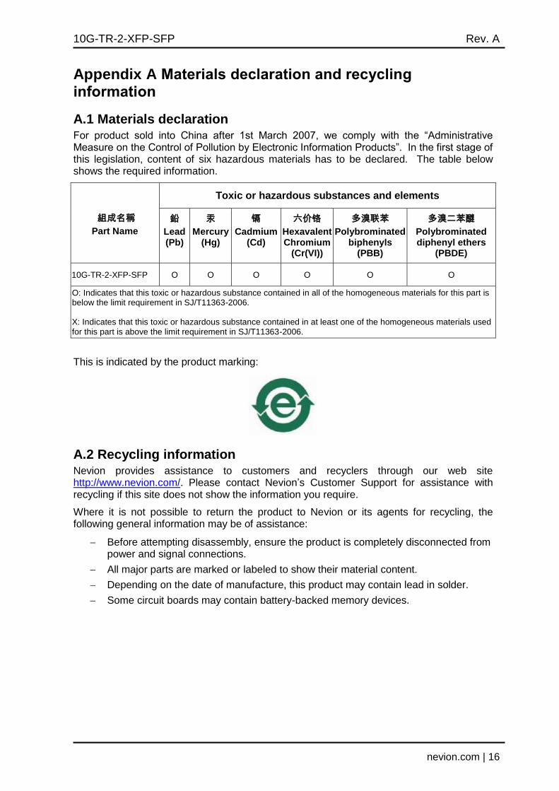
A.1 Materials declaration For product sold into China after 1st March 2007, we comply with the “Administrative Measure on the Control of Pollution by Electronic Information Products”. In the first stage of this legislation, content of six hazardous materials has to be declared. The table below shows the required information.
組成名稱
Part Name
Toxic or hazardous substances and elements
鉛
Lead (Pb)
汞
Mercury (Hg)
镉
Cadmium (Cd)
六价铬
Hexavalent Chromium
(Cr(VI))
多溴联苯
Polybrominated biphenyls
(PBB)
多溴二苯醚
Polybrominated diphenyl ethers
(PBDE)
10G-TR-2-XFP-SFP O O O O O O
O: Indicates that this toxic or hazardous substance contained in all of the homogeneous materials for this part is below the limit requirement in SJ/T11363-2006. X: Indicates that this toxic or hazardous substance contained in at least one of the homogeneous materials used for this part is above the limit requirement in SJ/T11363-2006.
This is indicated by the product marking:
A.2 Recycling information Nevion provides assistance to customers and recyclers through our web site http://www.nevion.com/. Please contact Nevion’s Customer Support for assistance with recycling if this site does not show the information you require.
Where it is not possible to return the product to Nevion or its agents for recycling, the following general information may be of assistance:
Before attempting disassembly, ensure the product is completely disconnected from power and signal connections.
All major parts are marked or labeled to show their material content.
Depending on the date of manufacture, this product may contain lead in solder.
Some circuit boards may contain battery-backed memory devices.