Embed Size (px)
DESCRIPTION
a notess
Citation preview

International Journal of Technology (2013) 2: 188‐199 ISSN 2086‐9614 © IJTech 2013
IMPACT OF TWO TYPES FLAT REFLECTOR MATERIALS ON SOLAR PANEL CHARACTERISTICS
Eko Adhi Setiawan1*, Khairiah Dewi1
1Electrical Engineering Department, Faculty of Engineering, Universitas Indonesia, Kampus Baru UI
Depok 16424, Indonesia
(Received: May 2013 / Revised: June 2013 / Accepted: July 2013)
ABSTRACT Reflector is used to increase the amount of solar radiation that the solar panels are exposed with, thus increasing the production of electric power. Parameters and I-V characteristic curve of a solar panel is strongly influenced by the amount of solar radiation received by the solar panels. This paper will discuss the effects of flat reflectors on the parameters and I-V characteristic curve of the solar panels. The parameters are solar radiation and temperature at solar panel, maximum power output (PMPP), voltage when PMPP is reached (VMPP), current when PMPP is reached (IMPP), short circuit current (ISC), open circuit voltage (VOC), and Fill Factor (FF). In this study, the types of reflector material are stainless steel mirror and aluminum foil. Reflector is placed beside solar panels. Reflector tilt angle was varied at 30, 45, 60, and 75 degrees. The measurement results show that the greatest increases in solar panel producing electric power are achieved at 75 degrees tilt angle. Aluminum foil reflector and stainless steel mirror can increase power output of solar panels until around 31.5 % and 21.5% respectively. In this tilt angle, for these two types of material reflector, VOC and VMPP tend not to change, ISC, IMPP, solar radiation and temperature on solar panel are increasing, whereas FF is decreasing around 4%. Changes in these parameters refer to the condition without a reflector. Keywords: Characteristics; Material; Reflector; Solar panel; Solar radiation; Tilt angle
1. INTRODUCTION Sunlight is one of the renewable energy resources and it can be converted into electrical energy by using solar cells. A collection of solar cells are assembled into solar panels, therefore it has a voltage and current greater than a solar cell. Solar panels are very suitable implemented in a place that has high sunlight intensity.Moreover the solar panels have several advantages, such as pollution-free during the process of conversion of solar energy into electrical power and low maintenance costs. It is also beneficial since sunlight has the highest power density compared to other renewable energies. However, the price of solar panel device and installation are quite expensive, so it costly for the initial investment.
For those reasons, user needs optimization on solar panel performance to generate electric power as much as possible. The greatest electrical power that can be produced by a solar panel indicates the optimal performance of the solar panels. Increasing solar radiation will also make the power output of solar panels increase. The amount of solar radiation at solar panel can be increased by reflector. It produces reflected light that will be exposed to the solar panel. Thus, the solar panels have two sources of sunlight.
* Corresponding author’s email: [email protected], Tel. +62‐21‐7270078, Fax. +62‐21‐7270077 Permalink/DOI: http://dx.doi.org/10.14716/ijtech.v5i1.108

Setiawan & Dewi 189
Besides, reflector is designed to have the same size or larger than the solar panels so that all reflected light falls onto the surface of the solar panel.
Research on the use of reflectors in solar panels has been conducted previously by other researchers. Tabaei and Ameri, for example, investigated that aluminium foil and stainless steel reflectors can increase power output around 8,5%-14% of polycrystalline solar panel (Tabei, 2012). Aziz-ul Haq also investigated the effect of single and two flat reflectors of aluminium to 40W solar panel (Hug, 2000). Rizk and Nagrial (2008), however, used 4W amorphous solar panels connected in series. They claimed that the affect found an increase of around 40% that can be achieved by using this method of concentration (Rizk & Nagrial, 2008). No one has showed the I-V characteristic curves of solar panel at direct measurement with a value of solar radiation (not the average solar radiation in one day) and short periods of time. Moreover, none of them discussed Fill Factor parameter affected by reflector.
The parameters of solar panel are maximum power output (PMPP), voltage when PMPP is reached (VMPP), current when PMPP is reached (IMPP), short circuit current (ISC), open circuit voltage (VOC), characteristic resistance (RCH), and Fill Factor (FF). Solar panels have the same calculation of solar cells, but differ only in the value of the quantity. Almost all of these parameters are illustrated in the I-V characteristic curve of solar panel. Equation for I-V curve of the solar cell is
I=IL-I0 exp -1 (1)
where: IL : light generated current (Ampere) q : 1.602 × 10⁻¹⁹ Coulomb I0 : dark saturation current (Ampere) V : voltage (Volt) I : current (Ampere) n : ideality factor T : temperature (Kelvin) K : Boltzmann's constant ISC is current when the voltage across the solar cell is zero. ISC, same as IL during the resistance of solar panel, is less than 10 Ωcm2 (Bowden & Honsberg, 2013). VOC is voltage when the current across the solar cell is zero. Equation for VOC is
VOC= lnIL
I0+1 (2)
The short-circuit current and the open-circuit voltage are the maximum current and voltage respectively from a solar cell. However, at both of these operating points, the power from the solar cell is zero. Equation for the power from the solar cell, P is P = I×V (3) ISC depends linearly on sunlight radiation at solar panel whereas VOC increases logarithmically with sunlight radiation at solar panel level as shown in the equation below (Bowden & Honsberg, 2013)
VOC= lnXISC
I0= ln
ISC
I0+ ln X =VOC+ ln X (4)

190 Impact of Two Types Flat Reflector Materials on Solar Panel Characteristics
X is an increase in sunlight radiation at solar panel level. FF is defined as the ratio of the maximum power from the solar cell to the product of VOC and ISC. The FF is illustrated below.
Figure 1. Fill Factor (Bowden & Honsberg, 2013)
Equation for FF is
FF=PMPP
VOC×ISC=
VMPP×IMPP
VOC×ISC (5)
RCH is the output resistance of the solar cell at its PMPP. If the resistance of the load is equal to the characteristic resistance of the solar cell, then the PMPP is transferred to the load. It is a useful parameter in solar cell analysis, particularly when examining the impact of parasitic loss mechanisms. The characteristic resistance is shown in the figure below.
Figure 2. Characteristic of resistance (Bowden & Honsberg, 2013)
Equation for RCH is
RCH = VMP
IMP (6)
It can alternately be given as an approximation where:
RCH = VOC
ISC (7)
Setiawan & Dewi 191
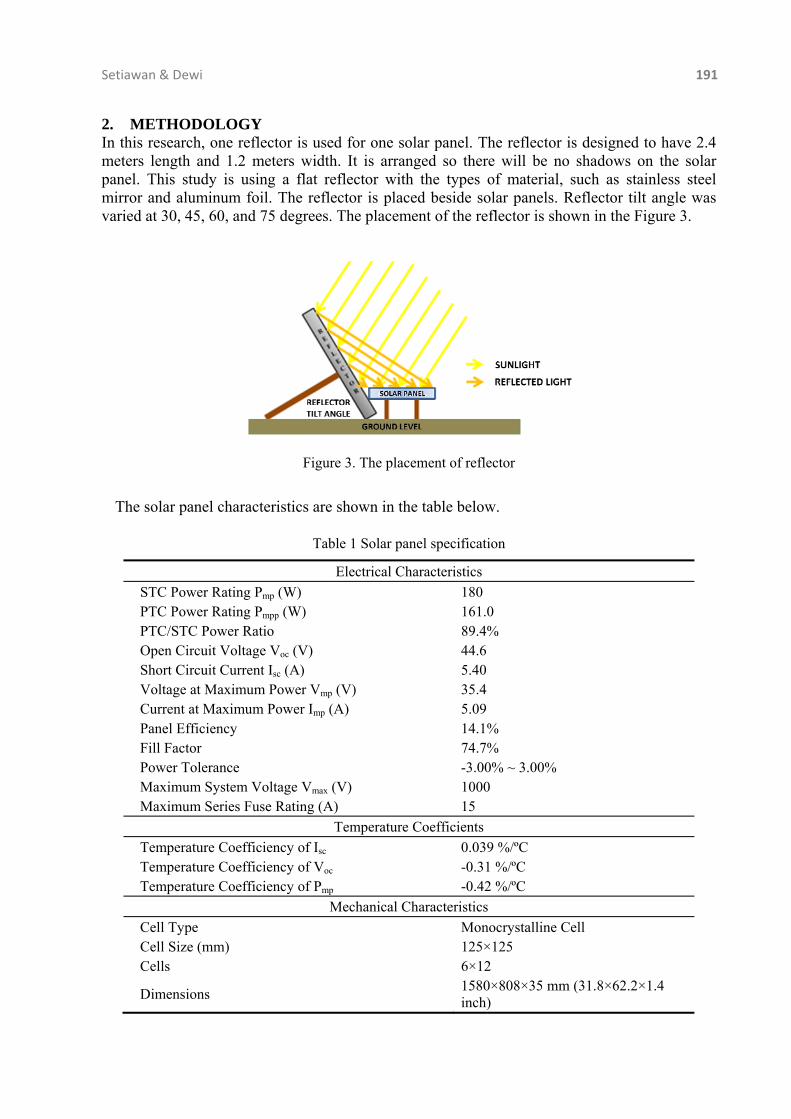
2. METHODOLOGY In this research, one reflector is used for one solar panel. The reflector is designed to have 2.4 meters length and 1.2 meters width. It is arranged so there will be no shadows on the solar panel. This study is using a flat reflector with the types of material, such as stainless steel mirror and aluminum foil. The reflector is placed beside solar panels. Reflector tilt angle was varied at 30, 45, 60, and 75 degrees. The placement of the reflector is shown in the Figure 3.
Figure 3. The placement of reflector
The solar panel characteristics are shown in the table below.
Table 1 Solar panel specification
Electrical Characteristics
STC Power Rating Pmp (W) 180 PTC Power Rating Pmpp (W) 161.0 PTC/STC Power Ratio 89.4% Open Circuit Voltage Voc (V) 44.6 Short Circuit Current Isc (A) 5.40 Voltage at Maximum Power Vmp (V) 35.4 Current at Maximum Power Imp (A) 5.09 Panel Efficiency 14.1% Fill Factor 74.7% Power Tolerance -3.00% ~ 3.00% Maximum System Voltage Vmax (V) 1000 Maximum Series Fuse Rating (A) 15
Temperature Coefficients
Temperature Coefficiency of Isc 0.039 %/ºC Temperature Coefficiency of Voc -0.31 %/ºC Temperature Coefficiency of Pmp -0.42 %/ºC
Mechanical Characteristics
Cell Type Monocrystalline Cell Cell Size (mm) 125×125 Cells 6×12
Dimensions 1580×808×35 mm (31.8×62.2×1.4 inch)

192 Impact of Two Types Flat Reflector Materials on Solar Panel Characteristics
Two solar panels were used during the experiment and measurement, one as a reference (without reflector) and the other is varied by using reflectors. Measurements were performed in Depok, West Java, Indonesia with position -6.36 south latitude and 106.82 longitude. A characteristics analyzer is measuring tool in this study. Researchers took measurements in the morning, May 3, 2013, at 09:25:26 until 10:18:10 local time. The measurements were made directly and refer to the EN 61829 standard about the direct measurement of the I-V characteristic curve of solar panels that determine the amount of solar radiation at solar panel level at least 700 Watt/m2 for accurate measurement results. 3. RESULTS AND DISCUSSION Results of this study are unique because the measurement result depends on the latitude and longitude that influence the position of the sun. Reflectors resulted in an increase of solar radiation at the solar panel level and solar panel temperature. The result is shown in the Figure 4.
748.8
777.0 787.0
930.7
734.5 732.0
756.5759.8
49.9
49.851.7
51.4
48.3
50.551.7 54.8
40
50
60
70
80
90
100
550
650
750
850
950
30 45 60 75
SOL
AR
PA
NE
L T
EM
PER
AT
UR
E (
CE
LC
IUS)
SO
LA
R R
AD
IAT
ION
AT
SO
LA
R P
AN
EL
(W
AT
T/M
2 )
REFLECTOR TILT ANGLE (DEGREES)
(A)
SOLAR RADIATION AT SOLAR PANEL - USING REFLECTOR
SOLAR RADIATION AT SOLAR PANEL - WITHOUT REFLECTOR
SOLAR PANEL TEMPERATURE - WITHOUT REFLECTOR
SOLAR PANEL TEMPERATURE - USING REFLECTOR

Setiawan & Dewi 193
Figure 4 Solar radiation and temperature with different angles of stainless steel reflector (A) and aluminium reflector (B)
From the measurement results, the solar panel obtains the greatest increase production of electric power (an optimal solar panel performance) by using of a reflector tilt angle at 75 degrees for both types of reflector material and the I-V characteristic curve is shown in the Figure 5.
820.4
806.0826.7
853.0
813.2
841.0858.8
1,070.1
50.1
50.652.3 51.2
48.8
52.3 53.0 55.3
40
50
60
70
80
90
100
600
700
800
900
1000
1100
30 45 60 75
SOL
AR
PA
NE
L T
EM
PER
AT
UR
E (
CE
LC
IUS)
SO
LA
R R
AD
IAT
ION
AT
SO
LA
R P
AN
EL
(W
AT
T/M
2 )
REFLECTOR TILT ANGLE (DEGREES)
(B)
SOLAR RADIATION AT SOLAR PANEL LEVEL - WITHOUT REFLECTOR
SOLAR PANEL RADIATION AT SOLAR PANEL LEVEL - USING REFLECTOR
SOLAR PANEL TEMPERATURE - WITHOUT REFLECTOR
SOLAR PANEL TEMPERATURE - USING REFLECTOR

194 Impact of Two Types Flat Reflector Materials on Solar Panel Characteristics
Figure 5. I-V and P-V curve of solar panel with different reflector materials.The P-V curve is calculated from the measured I-V curve
0
30
60
90
120
150
180
210
240
270
300
0
0.62
1.24
1.86
2.48
3.1
3.72
4.34
4.96
5.58
6.2
0 4 8 12 16 20 24 28 32 36 40
P (W
AT
T)
I (A
MP
ER
E)
V (VOLT)
(A)
I-V CURVE - WITHOUT REFLECTOR
I-V CURVE - USING STAINLESS STEEL MIRROR REFLECTOR AT 75 DEGREES TILT ANGLE
P-V CURVE - WITHOUT REFLECTOR
P-V CURVE - USING STAINLESS STEEL MIRROR REFLECTOR AT 75 DEGREES TILT ANGLE
0
30
60
90
120
150
180
210
240
270
300
0
0.62
1.24
1.86
2.48
3.1
3.72
4.34
4.96
5.58
6.2
0 4 8 12 16 20 24 28 32 36 40
P (W
AT
T)
I (A
MP
ER
E)
V (VOLT)
(B)
I-V CURVE - WITHOUT REFLECTOR
I-V CURVE - USING ALUMINIUM FOIL REFLECTOR AT 75 DEGREES TILT ANGLE
P-V CURVE - WITHOUT REFLECTOR
P-V CURVE - USING ALUMINIUM FOIL REFLECTOR AT 75 DEGREES TILT ANGEL

Setiawan & Dewi 195
Figure 6. Solar panel characteristic parameters after using two types reflector materials in details
The results of measurements by looking at the percentage increment of each parameter from reference (without reflector) of solar panels are shown in equation below.
(8)
If the percentage shows positive value, there is an increase, and if the value is negative, there is a decrease from the reference conditions.

196 Impact of Two Types Flat Reflector Materials on Solar Panel Characteristics
Table 2 Summary of solar panel parameters with stainless steel and aluminium reflector
Material Type of Reflector
IMPP
(Ampere) VMPP
(Volt) PMPP
(Watt) ISC
(Ampere) VOC
(Volt) Fill Factor
Stainless Steel Mirror 21.1% 0.31% 21.5% 27.4% 0.3% -4.1%
Aluminium Foil 34.3% -2.00% 31.5% 36.0% 0.7% -4.1%
Table 2 shows that the reflector makes PMPP increase in solar radiation at solar panel level (see curve before). Solar radiation increases lead to increased temperatures on the solar panel. The efficiency benefits of reflector may be reduced by increased losses in series resistance as the ISC current increases and also by the increased temperature operation of the solar panel. As losses due to ISC depend on the square of the current, power loss due to series resistance increases as the square of the reflector (Bowden & Honsberg, 2013). However, the measurement results show that the increased solar radiation more strongly influences the rise PMPP and there is no power loss. Decreased PMPP occurs when solar radiation decreases. From the measurement results, it can be seen that the reflector made of aluminium foil is the best because it produces larger increase in PMPP.
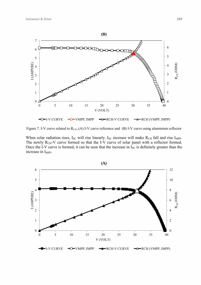
The measurement result indicates that the increase in solar radiation resulting from the use of reflectors making an influence on the increasing in current solar panels either IMPP or ISC. For voltage, both VMPP and VOC, the resulting increase in radiation due to the use of reflectors does not make changes in the value of the voltage. There were very small changes that happen once. Theoretically, at the same temperature, the amount of VOC is directly proportional to the logarithmic increase in solar radiation and ISC linearly proportional to the increase in solar radiation. FF decreases due to an increase in solar radiation caused by the use of reflectors. This is because the increase in the value of ISC is greater than IMPP. ISC increases greater than IMPP due to decrease in RCH. The decreasing characteristic resistance is shown in the figure below.
0
2
4
6
8
10
12
0
1
2
3
4
5
6
7
0 5 10 15 20 25 30 35 40
RC
H(O
HM
)
I (A
MP
ER
E)
V (VOLT)
(A)
I-V CURVE VMPP, IMPP RCH-V CURVE RCH (VMPP, IMPP)
Setiawan & Dewi 197
Figure 7. I-V curve related to RCH ,(A) I-V curve reference and (B) I-V curve using aluminium reflector When solar radiation rises, ISC will rise linearly. ISC increase will make RCH fall and rise IMPP. The newly RCH-V curve formed so that the I-V curve of solar panel with a reflector formed. Once the I-V curve is formed, it can be seen that the increase in ISC is definitely greater than the increase in IMPP.
0
1
2
3
4
5
6
0
1
2
3
4
5
6
7
0 5 10 15 20 25 30 35 40
RC
H(O
HM
)
I (A
MP
ER
E)
V (VOLT)
(B)
I-V CURVE VMPP, IMPP RCH-V CURVE RCH (VMPP, IMPP)
0
2
4
6
8
10
12
0
1
2
3
4
5
6
0 5 10 15 20 25 30 35 40
RC
H(O
HM
)
I (A
MP
ER
E)
V (VOLT)
(A)
I-V CURVE VMPP, IMPP RCH-V CURVE RCH (VMPP, IMPP)

198 Impact of Two Types Flat Reflector Materials on Solar Panel Characteristics
Figure 8. I-V curve related to RCH ,(A) I-V curve reference and (B) I-V curve using stainless steel reflector
Greater reduction in RCH makes the larger increase in PMPP, but is not necessarily the value of FF to decrease. In this study, RCH value only affected the increase occurring between IMPP and ISC because the value of VOC and VMPP likely remain. Thus, the value of FF will change according to the ratio of the increase IMPP and ISC. If ISC is much larger increase than the increase IMPP, the FF value will drop even further.
The measurement result shows that by using aluminium reflector, the increase of ISC (around 6 A) exceeds the data sheet standard (ISC factory characteristic 5.4 A). Consequently, it can impact on destruction of solar panels itself.
The measurement results also show that the I-V characteristic curve from solar panel without using reflectors is smaller than I-V characteristic curve from solar panel using the reflector. This is due to an increase in solar radiation which causes changes to almost the entire parameters characteristic of the solar panels. Slight slope in the I-V curve, both slope down or up, occur due to thin clouds that block sunlight when the measurement took place. 4. CONCLUSION Laying the right tilt angle and type of reflectors material can boost the performance of solar panels to generate electrical power. In this case, 75 degree of tilt angle aluminium foil reflector and stainless steel mirror can increase power output of solar panel until around 31.5 % and 21.5% respectively. However the FF/fill factor is decreasing around 4%, it indicates that the ratio of the maximum power from the solar panel to the product of VOC and ISC is reduced. 5. ACKNOWLEDGEMENT The authors are grateful to the TASPE (The Academy of Solar Power Education) - Universitas Indonesia for solar characteristics analyser measurement unit support and the valuable comments of the reviewers.
0
1
2
3
4
5
6
7
8
0
1
2
3
4
5
6
0 5 10 15 20 25 30 35 40
RC
H(O
HM
)
I (A
MP
ER
E)
V (VOLT)
(B)
I-V CURVE VMPP, IMPP RCH-V CURVE RCH (VMPP, IMPP)

Setiawan & Dewi 199
6. REFERENCES Bowden, Stuart., Honsberg, Christiana., Instructions on Photovoltaic, [Online], Available at:
http://www.pveducation.org/pvcdrom/instructions [March-June 2013] Huq, D., 2000. Effect of Flat Reflector on the Performance of Photovoltaic Module. Copyright
2000 by the American Institute ofAeronautics and Astronautics, Inc. All rightsreserved. Rizk, J., Nagrial, M.H., 2008. Impact of Reflectors on Solar Energy Systems. World Academy
of Science, Engineering Technology Tabaei, H., 2012. The Effect of Booster Reflectors on the Photovoltaic Water Pumping System
Performance. Journal of Solar Energy Engineering, Volume 134/014501-1