Embed Size (px)
Citation preview

1
Service control manual Smart HP
Application FLBB0mHPGU

2
Summary 1. INTRODUCTION .......................................................................................................................................................................................................................3
1.1 Purpose of the manual ................................................................................................................................................................................................3 2. SYSTEM ARCHITECTURE ......................................................................................................................................................................................................4
2.1 Main control components .........................................................................................................................................................................................4 3. USER INTERFACE .....................................................................................................................................................................................................................5
3.1 Terminal .............................................................................................................................................................................................................................5 4. PROGRAMMING OF THE CONTROL ...............................................................................................................................................................................6
4.1 PROGRAMMING BOARDS ..........................................................................................................................................................................................6 4.2 Programming description with PCO manager ..................................................................................................................................................6
4.2.1 PCO Manager installation ..............................................................................................................................................................................6 4.2.2 PC Connection - µPC control ........................................................................................................................................................................6 4.2.3 Board programming .........................................................................................................................................................................................7 4.2.4 Addressing the terminal .................................................................................................................................................................................8 4.2.5 Addressing of the µPC board .......................................................................................................................................................................9
5. DESCRIPTION OF THE MENU.......................................................................................................................................................................................... 11 5.1 Control menu ................................................................................................................................................................................................................ 11
5.1.1 Main screen ...................................................................................................................................................................................................... 11 5.1.2 Structure of the menus................................................................................................................................................................................ 12
6. USER MENU ........................................................................................................................................................................................................................... 13 6.1 Introduction ................................................................................................................................................................................................................... 13
6.2 A. On/Off Unit...................................................................................................................................................................................................... 13
6.3 B. Setpoint ............................................................................................................................................................................................................. 14
6.4 C. Clock/Time bands ......................................................................................................................................................................................... 17
6.5 D. Inputs/Outputs .............................................................................................................................................................................................. 21
6.6 E. Alarms log ......................................................................................................................................................................................................... 25
6.7 F. Change Board.................................................................................................................................................................................................. 26 7. ASSISTANCE MENU ............................................................................................................................................................................................................. 27
7.1 G. Assistance ........................................................................................................................................................................................................ 27 7.2 G.a. Change language ............................................................................................................................................................................................... 27 7.3 G.b. Information .......................................................................................................................................................................................................... 27 7.4 G.c. Heat regulator unit ........................................................................................................................................................................................... 28 7.5 G.d. Hours worked ..................................................................................................................................................................................................... 28 7.6 G.e. Config. BMS .......................................................................................................................................................................................................... 29 7.7 G.f. Assistance Parameters ..................................................................................................................................................................................... 29
7.7.1 Hour counter settings .......................................................................................................................................................................................... 29 7.7.2 Probe calibration .................................................................................................................................................................................................. 29 7.7.3 Thermo regulation ............................................................................................................................................................................................... 31 7.7.3.1 Change summer/winter selection .......................................................................................................................................................... 31 7.7.3.2 Integrated devices to the main heat pump ....................................................................................................................................... 31 7.7.3.3 Compensation setpoint to the main (only in hydronic heat pump units) ........................................................................... 33 7.7.3.4 Anti-freeze ......................................................................................................................................................................................................... 33 7.7.3.5 General relay alarm ....................................................................................................................................................................................... 34 7.7.3.6 Defrosting .......................................................................................................................................................................................................... 34 7.7.3.7 External battery ventilation ....................................................................................................................................................................... 37 7.7.3.8 Overheating management and related alarms ................................................................................................................................ 38 7.7.4 Reset alarm log and change Assistance password ......................................................................................................................................... 39
7.8 G.g. Manual management ...................................................................................................................................................................................... 39
7.9 H. MANUFACTURER'S MENU ....................................................................................................................................................................... 39 8. ALARMS ................................................................................................................................................................................................................................... 40
8.1 View and reset alarms .............................................................................................................................................................................................. 40 8.2 Table of alarms ............................................................................................................................................................................................................. 40

3
1. INTRODUCTION
1.1 Purpose of the manual
The purpose of this manual is to give all the information required for the Assistance Centres concerning the use of the
control within the application on the Epsilon Echos + units, with the FLBBomHPGU application.
Information concerning installation of the units, and the relative checks and inspections for first commissioning, are
not shown in this manual; please refer to the unit's installation for use and maintenance manual.
It goes without saying that correct installation of the unit, performance of checks and controls before start-up and
routine maintenance will be performed according to Blue Box information in the relative manual.
We would like to thank in advance anyone collaborating by signalling errors, parts that require further explanation or
functioning modes not stated.

4
2. SYSTEM ARCHITECTURE
2.1 Main control components
The following figure illustrates the system's architecture formed by the μPC programmable board on which the
FLBB0mHPGU application is installed and the main components connected to it, which, however, depend on the unit's
configuration.
Description
1 µPC Board
2 pDG1 terminal + telephone cable
4 Unipolar electronic expansion valve (with driver integrated into the µPC board)
5 Inverter Power+ to drive the BLDC compressor
6 Serial board for BMS

5
3. USER INTERFACE
3.1 Terminal
The user interface consists of a display with 8 rows and 22 columns with 6 keys. Through this interface, you can start
and stop the unit, set the parameters and check the operation.
The functions of the six keys are:
The “up arrow” key: used to scroll the masks of the various sections, which are modified by
increasing the selected values.
The “down arrow” key: used to scroll the masks of the various sections, which are modified by
decreasing the selected values.
The “enter” key: confirms the selection made to access the various sections, provides access to the
values that are to be modifies with the arrow keys and confirms the modification made.
The “alarm” key: lights up if an anomaly or alarm is signalled; all the active alarms are displayed and
possibly deleted when pressed.
The “Prg” key: provides access to the loop of masks of the various branches.
The “Esc” key: is used to return to the upper mask level.

6
4. PROGRAMMING OF THE CONTROL
4.1 PROGRAMMING BOARDS
During work phases on the unit it is essential to pay attention to the safety devices prescribed by the
company for accident prevention and safety regulations in force.
Boards are programmed via computer.
Before electrically powering the µPC board, make the connection between the µPC board and the
computer and start the programming software.
Disconnect all the serials connected to the µPC board before programming. The serials are to be
reconnected after programming completion and before turning on the unit.
Before installing the files in the "Application" drop-down, check that the "bios" on the board has the
same version as that with which the software was approved.
If not, update the ''bios'' before downloading the ''Application'' drop-down files:
The boards must be programmed by individually powering them.
If more boards are present, set the addressing in the manual before connecting them via serial.
4.2 Programming description with PCO manager
PCO Manager is a program that supervises all configuration, debugging, and maintenance operation of the CAREL PCO
system devices.
4.2.1 PCO Manager installation
On the websitehttp://ksa.carel.com, in the PCO system section, select PCO_manager. After accepting the general
licence terms for free use of the software, a window opens with the option to download the
file PCO_manager.zip. Install the program on the computer.
4.2.2 PC Connection - µPC control
The computer's USB port must be connected with an enabled cable for the cable USB/RS485 converter and this must
be connected with a telephone cable to the μPC's pLAN port.

7
When the PCO_manager program opens, a screen appears in the upper right part the connection settings appear.
Select:
1) local connection;
2) baud rate: Auto;
3) find device: Auto (pLAN).
With reference to the port number, follow the wizard's instructions for
automatic identification (for example COM4).
Use the mouse to click on the icon to start the connection and power the µPC* board.
When the word "ONLINE" appears in the bottom left corner, the connection between the μPC* board and the
computer is enabled.
4.2.3 Board programming
Select the bios file by checking the BIOS field box
and search for the file in the path selected for saving through the key
At this point, select the application (Caution: the paths shown in the pictures below serve only as a guide, carefully
select the correct files):
and search for the file in the path selected for saving through the key
In the drop down menu select the *iup checking the box for the language required.
Now select the *BIN file.

8
Select the *DEV file.
The *DEV file in the application inserts the default file, but the operator can download the most suitable *DEV file for
the machine to be programmed by selecting via the key "Add DEV file..."
Now it is possible to start the download procedure clicking on the "Upload" key.
Wait for the procedure to finish.
Once programming is complete remove power from the µPC board and disconnect the RS485 converter.
4.2.4 Addressing the terminal
The terminal's address must be set to 32.
It is impossible to configure the terminal's address only after having supplied power to it through the FJ12 connector. To
enter configuration mode simultaneously press , and for at least 5 seconds; the terminal will display a mask
similar to the following, with the cursor flashing in the upper left corner:
To change the terminal address ("Display address setting"), the following operations must be performed in sequence.
1. Press once : the cursor will move to field "Display address setting".

9
2. Select the desired value through and , confirm pressing again
3. If the value selected is different from the one stored, the following mask and the new value will be stored in
the display's permanent memory.
Note: if during functioning the terminal detects the μPC board's idle state of which output is being
displayed, it will completely erase the display and the following message (or similar) will appear:
If the terminal detects the inactivity of the entire pLAN network, that is it does not receive any message from the
network for 10 consecutive seconds, it will completely erase the display and the following message will appear:
4.2.5 Addressing of the µPC board
To complete the installation procedure, the pLAN address must be set on the μPC board; the µPC/µPCxs controllers
do not
have dipswitches for network pLAN addressing: the pLAN address change is made through any gGD1 terminal.
1. Set the address to 0 on the terminal, (refer to the previous sections for details on how to select such
address).
2. Remove power from the µPC.
3. Remove any pLAN connections with other boards from the µPC board.
4. Connect the terminal to the µPC.
5. Power the µPC, by simultaneously pressing the UP and ALARM keys on the terminal. After a few seconds, the
µPC begins a start sequence and a screen similar to the following will appear on the display:
Wait 10 seconds after the screen appears and then release the keys.
The µPC interrupts the start sequence and shows a configuration screen similar to the following:
At this point, change the pLAN address via the terminal keys and .
1. Confirm the address pressing the key : the µPC board completes the start sequence and uses the
address specified.
2. Set the PGD1's address to 32

10
Attention: if the settings are not correct, the text and images on the display will appear incorrect.

11
5. DESCRIPTION OF THE MENU
5.1 Control menu
The series of information that appears on the display is collected in masks which, in turn, are grouped into
homogeneous groups.
You can access some functions at any time through the keys, while others are present only when there are the
necessary conditions (e.g. signal and alarm conditions).
The masks that can be accessed at any time are organised in a flow chart, with a main menu and various subgroups.
Some menus are accessible only via password and are reserved for Assistance or for the Manufacturer.
Some control functions are not active, but the name is only present on the menu with its masks.
5.1.1 Main screen
The rows of the main screen display are organised as follows:
1- indications of date and time;
2- main parameters and active request:
No active request
Cold water request from the main circuit (hydronic) or cold operation
(direct expansion)
Cold water request from the main circuit (hydronic) or cold operation
(direct expansion); for reversible heat pump units only
3- main active components:
Compressor switched on
Main circuit pump switched on (if present)
Active integration system (heater or boiler) (if present)
Defrost in progress (for reversible heat pump units only)
Smartlink Machine connected to Swegon unit is controlled with Smartlink
4- unit status:
The states in which the unit can be found are as follows:
ON Unit switched on (standard setpoint)
ENERGY SAVE Unit switched on (energy save setpoint)
OFF Unit switched off from the keyboard
Auto-ON Unit switched on (time band operation, standard setpoint)
Auto-E.S. Unit switched on (time band operation, energy save setpoint)
Auto-OFF Unit switched off (time band operation)
BMS-OFF or Din-OFF Unit switched off remotely
Alarm-OFF Unit switched off due to alarm
Protect Unit in stand-by for temporary Unit Off enabling

12
5.1.2 Structure of the menus
By pressing the key, you will access the navigation screen of the main menu:
The following are the eight menus with their respective sub-menus:
A. Unit On-Off
B. Setpoint
C. Clock/Time bands
D. Inputs/Outputs
E. Alarms log
F. Change Board
G. Assistance
a. Change language
b. Information
c. Hours worked
d. Config.BMS
e. Maintenance
Parameters
a. Hour counter settings
b. Probe adjustment
c. Thermo regulation
d. userdef./changePW1
f. Manual management
H. Manufacturer
Access to password-protected branches is reserved to authorised Service Centres or to the Manufacturer.
To access these
branches, you m
ust enter the
password PW
1
To access these
branches, you m
ust enter
the password PW
2

13
6. USER MENU
6.1 Introduction
This chapter describes the unit's main functions, which can be accessed from the user menu without password use.
6.2 A. On/Off Unit
From the main screen, press the key
With the arrows, move the cursor over menu A. Unit On/Off and press the key
The following screen will appear:
+----------------------+ | Unit On/Off A01| | | |Hydronic unit |
|Summer | | | |ON | | | | | +----------------------+
The first row shows the unit type (not editable).
By pressing the key, the cursor will blink on the second row (only if unit is OFF) where you can select the unit
status with the arrows:
SUMMER
WINTER
The WINTER status is only available if the unit is a heat pump or a reversible condensing unit.
The change of the status can be carried out only if the unit is OFF.
The status change can also be carried out by an external controller via a digital input; this function inhibits the status
change from keyboard and must be enabled by an authorised Service Centre.
By pressing the key, the cursor blinks on the third row where, by pressing the and keys, you can
turn the unit on or off by selecting one of the available modes:
ON = unit switched on
OFF = unit in stand-by
ENERGY SAVING = unit switched on with a setpoint different than the standard ones, for energy saving (function not
available for condensing unit and reversible condensing unit)
AUTO = the switching on-off of the unit is determined according to the time bands set with the scheduler.
Once the mode is selected, press the key to confirm.
Note: the unit's switching on and off is time-controlled.
By pressing , you will pass to the next mask A02 (for hydronic units only), where you can enable or disable the
temporary unit function OFF; this function allows you to stop the unit, setting it in the OFF mode, to then let it start
again at the set time (date and time).

14
+----------------------+ | On/Off Unit A02|
| | |Off temporary unit|
|enabling: NO | |Restart the: 00/00/00| |Time: 00:00| | |
|Enable the function: NO| +----------------------+
To enable the function:
Press the key and, with the arrows, select YES in the "temporary unit enabling Off" row.
By pressing the key, the cursor will blink on the unit reboot date; set the date with the arrows and press
to confirm.
By pressing the key, the cursor will blink on the unit reboot time; set the desired time with the arrows and press
to confirm (Note: you can only set the hour, not the minutes).
Press the key and select YES with the arrows in the "Start function" row.
The unit status displayed on the main screen will change into "Protect" (see par. 3.1.1); the unit will enter the stand-by
mode and will reboot at the set date and time.
Warning: before activating this function, make sure that the unit's clock (date and time) is correctly set (see par. 4.4).
Add. Message displayed Description Default U.M. Min Max Possible values
A01
Hydronic unit Condensing unit (depending on the type of unit selected)
Summer/Winter selection (for reversible units)
Summer ---
On/Off time bands if enabled OFF ---
A02
Enabling Off temporary unit:
Enable function "Restart the"
NO
Day restart function "Restart the" --- dd
Month restart function "Restart the"
--- mm
Year restart function "Restart the" --- yy
Hour restart function "Restart the"
--- h
Enable the function:
Start the function "Restart the" 0 ---
6.3 B. Setpoint
The menu allows setting the setpoint for the chiller and heat pump units; you cannot set the setpoint for the
condensing and reversible condensing units because the request originates from the connected external unit
For hydronic units, the main adjustment handled by the control is carried out on the water temperature at the water
circuit infeed.
The adjustment band and the type of adjustment are established by the manufacturer, any winter temperature
compensation (accessory) and temperature limits are set in the Assistance branch.

15
The following diagram shows the summer thermostat control for the compressor, referring to the chiller working
setpoint:
Instead, the following diagram shows the winter thermostat control for the compressor, referring to the heat pump's
working setpoint (for reversible units):
In the winter operational mode, electrical heaters inserted in the heat exchanger or boiler which receives a remote
on-off and works with its own set setpoint can be used as system integration or replacement for the heat pump. The
activation of the integrated source occurs for external air temperature; this setting is performed in the appropriate
mask in the Assistance branch.
To set the setpoints, press the key from the main screen
With the arrows, move the cursor over menu B. Setpoint and press
The following mask will appear to set the nominal operating setpoint in chiller and in heat pump modes (the latter, if
unit is reversible):
Setpoint
Diff.
Circuit
ref. temp.
OFF
ON
OFF
ON
Setpoint
Diff.
Circuit
ref. temp.

16
+----------------------+ | Heat regulat. Unit B01| |Temp.PdC | | | |Nominal setpoints (ON)|
|Cooling: 7.0°C| |Heating: 45.0°C|
| | | | +----------------------+
To pass to the mask with the energy save setpoints, press the key
+----------------------+ | Heat regulat. Unit B02| |Temp.PdC | | | |Setpoint energy save |
|Cooling: 10.0°C |Heating: 40.0°C
| | | | +----------------------+
In both masks, by pressing the key, the cursor highlights the setpoint values to be edited from time to time; set
the desired value using the arrows and press the key to confirm the set value and move to the next value.
The table describes the different branch mask fields.
Add. Message displayed Description Default U.M. Min Max Possible values
B01
Comfort temperature setpoint (summer)
7.0 °C 5.0 18.0
Comfort temperature setpoint (winter) only in reversible units
45.0 °C 30.0 50.0
B02
Economy temperature setpoint (summer) 10.0 °C 5.0 18.0
Economy temperature setpoint (winter) only in reversible units
40.0 °C 30.0 50.0
NOTE: LE motocondensing units and LE/HP reversible motocondensing do not have values that can be set in the
Setpoint menu, for these branch B. units, Setpoint only appears for the B03 mask that shows the percentage of
required power to the compressor (display only), coming from the external signal.

17
+----------------------+
| Heat regulat. B03 Unit| | |
|Power required at | |compressor: |
| 000.0%| | | | | | | +----------------------+
6.4 C. Clock/Time bands
The control is equipped with an internal clock with backup battery that keeps the date and time even with the
machine is switched off. The setting of the date and time is carried out through the first mask of the object menu: by
pressing the key, the cursor highlights the fields to edit from time to time by pressing the and
keys; set the values by pressing the key to confirm the set value and you will pass to the next field.
+----------------------+ | Clock C01|
| | |Day: Monday|
| | | dd/mm/yy| |Date: 00/00/00| | |
|Time: 00:00| +----------------------+
Once date and time are set, press the key to pass to the screen where you can set the time bands.
The setting of time bands allows 4 operating ranges to be set for each day of the week. It is possible to set time bands
for start-up/shutdown, and the status of unit operation from those available.
Warning: setting the time bands is possible only if the unit is in AUTO mode (see par. 4.2).
+----------------------+ | Clock C02|
| | |Day MONDAY |
|Copy in TUESDAY NO| |F1 08:30 ON |
|F2 12:30 ENERGY SAVE| |F3 13:30 ON | |F4 17:30 OFF | +----------------------+
For each day of the week, there are 4 programmable time bands (F1, F2, F3, F4). By pressing the key and the
arrows, you can select the day of the week on which to programme the time bands; by pressing the key, you
can pass to the next rows allowing you to select the desired values with the arrows.
For each band, you must set:
• The starting hour of the time band;
• The status of the considered unit, which can be: ON, OFF, ENERGY SAVE (see par. Setpoint).
Once you have set the 4 time bands for a day, if you want to use them for other days of the week, you can copy them:
by pressing the key, move the cursor on the second row and select the day of the week on which you want to

18
copy the programmed time bands with the arrows; press and select Yes with the arrows; after a few seconds, if
the operation was successful, the message <<SUCCESSFUL COPY>> will appear on the second row, which will
disappear after about 5 seconds. Repeat this procedure if you want to copy the programmed day on other days of the
week.
The key will move you to the next screen where holiday periods (maximum 3) and their relative unit status (ON,
OFF, SAVE ENERGY) can be enabled and set. The starting date Start and the end date Stop, expressed as dd/mm must
be set for each period.
The holiday periods are enabled by selecting YES from the first row, select NO for disabled.
+----------------------+ | Clock C03|
|Enab.holiday periods:NO | |Start1 --/-- ON | |Stop1 --/-- | |Start2 --/-- OFF | |Stop2 --/-- | |Start3 --/-- ENERGY S.| |Stop3 --/-- | +----------------------+
The key will move you to the next screen where special days (maximum 6), and their relative unit status (ON,
OFF, SAVE ENERGY) can be enabled and set; other than those scheduled in time bands or during holiday periods.
The date is expressed as dd/mm. The special days are enabled by selecting YES from the first row, select NO to disable
the function.
+----------------------+ | Clock C04|
|Enab.special days: NO | |SD1 --/-- OFF | |SD2 --/-- OFF | |SD3 --/-- OFF | |SD4 --/-- OFF | |SD5 --/-- OFF | |SD6 --/-- OFF | +----------------------+
The key will move you to the next screen where daylight saving time can be enabled and set. Press the key
and the arrows to enable or disable the automatic switch to and from daylight saving time. The other
parameters are set by default.
+----------------------+ | Clock C05|
| | |Daylight saving time: ENABLE|
|Transit. time: 60min |Start.:LAST SUNDAY|
|in MARCH at 03.00| |End: LAST SUNDAY|
|in OCTOBER at 03.00| +----------------------+

19
Index Message displayed Description Default U.M. Min Max Possible values
C01
Day of the week calculated on the basis at the actual date
---
Day Setting (dd) dd
Month setting (mm) mm
Year setting (yy) yy
Hour setting h
Minute setting m
C02 (fields
enabled if "AUTO"
enabled in the A01 mask)
Setting of the day ---
Day to be copied for time bands ---
Begin copy of the time bands for the actual day.
---
Hour setting start band 1
h
Minutes setting start band 1
m
Setpoint type setting band 1
---
Hour setting start band 2
h
Minute setting start band 2
m
Setpoint type setting band 2
---
Hour setting start band 3
h
Minute setting start band 3
m
Setpoint type setting band 3
---
Hour setting start band 4
h
Minute setting start band 4
m
Setpoint type setting band 4
---
C03
Enabling of machine holiday periods. ---
Day setting start period 1
dd
Month setting start period 1 mm
Setpoint type setting period 1 ---
Day setting end period 1
dd
Month setting end period 1 mm
Day setting start period 2
---
Month setting start period 2
---

20
Index Message displayed Description Default U.M. Min Max Possible values
Setpoint type setting period 2 ---
Day setting end period 2 dd
Month setting end period 2
mm
Day setting start period 3 dd
Month setting start period 3 mm
Setpoint type setting period 3 ---
Day setting end period 3 dd
Month setting end period 3
mm
C04
Enabling of machine special days
---
Day setting, special day 1 dd
Month setting, special day 1
mm
Setpoint type setting special day 1
---
Day setting, special day 2
dd
Month setting, special day 2
mm
Setpoint type setting special day 2
---
Day setting, special day 3
dd
Month setting, special day 3 mm
Setpoint type setting special day 3
---
Day setting, special day 4
dd
Month setting, special day 4 mm
Setpoint type setting special day 4 ---
Day setting, special day 5 dd
Month setting, special day 5 mm
Setpoint type setting special day 5 ---
Day setting, special day 6 dd
Month setting, special day 6
mm
Setpoint type setting special day 6
---
C05
Enable daylight saving time ---
Offset time m
Week of the month daylight saving starts
---

21
Index Message displayed Description Default U.M. Min Max Possible values
Day of the week daylight saving starts
dd
Month daylight saving starts
mm
Hour of the day, daylight saving starts
h
Week of the month daylight saving ends ---
Day of the week daylight savings ends
dd
Month daylight savings ends
mm
Hour of the day, daylight savings ends h
6.5 D. Inputs/Outputs
From this menu, you can view, in sequence:
• The values read by the probes connected to the analogue inputs;
• the physical state of the digital inputs;
• the physical state of the digital outputs;
• the values of the analogue outputs;
• the operating parameters of the cooling unit;
• the operating parameters of the inverter.
Inputs and outputs change according to the model and the unit's configuration. If the inputs or outputs have not been
set (no device or probe connected) a symbol will appear "-" or the item relating to the mask will not be present.
Add. Message displayed Description Def. U.M. Min Max Possible values
D01
Temperature of the external heat exchanger (finned-coil) --- °C
D02
Main return water temperature (only for CH and HP units) --- °C
D03
External air temperature --- °C
D04
Main flow water temperature (only CH and HP unit)
--- °C

22
Add. Message displayed Description Def. U.M. Min Max Possible values
D05
Compressor discharge temperature --- °C
Compressor intake temperature --- °C
D06
Condensing pressure read by the high pressure transducer
--- barg
High pressure converted into temperature --- °C
Evaporation pressure read by the low pressure transducer
--- barg
Low pressure converted into temperature --- °C
D07
ID1= Fan circuit breaker --- ---
ID2=Summer/winter --- ---
ID3=High pressure switch --- ---
ID4= Thermal pump --- ---
D08
ID7= Boiler alarm/electrical heater system integration --- ---
ID8= On/off remote --- ---
-
ID10= Main circuit flow switch --- ---
D10
NO1= Compressor 1 --- ---
NO2= - --- ---
NO3= Main circuit pump --- ---
NO4= - --- ---
D11
NO5= Defrost (only for reversible unit) --- ---
NO6= Boiler/integrated electrical heater (if enabled)
--- ---
NO7= General alarm --- ---
NO8= - --- ---
D12
NO9= -
NO10= 4 way valve (only for reversible unit)
--- ---
NO11= status change summer/winter (only for reversible unit) --- ---
D13
Y1= - --- %
Y2= - --- %
Y3= - --- %
Y4= external battery fan percentages --- %
D14
Actual overheating --- K
Intake temperature --- °C
EEV Position --- steps
Valve A percentage open --- %
EVD electronic expansion valve status ---

23
Add. Message displayed Description Def. U.M. Min Max Possible values
Evaporation pressure --- barg
Evaporation temperature; --- °C
D15
External DI1 EVO EVD status (not utilised) --- ---
External DI2 EVO EVD status (not utilised)
--- ---
D16
BLDC compressor power required from thermo regulation
--- %
BLDC compressor power limited by management envelope --- %
Instantaneous speed of the compressor --- rps
View pressure balance status (flashing) --- ---
Work area 1c - max speed 90 rps (only Siam)
--- ---
D17
Compressor discharge gas overheating --- °C
Compressor discharge gas temperature --- °C
D18
Ability to request Power+ --- %
Capacity actually delivered by the compressor
--- %
Actual rotational speed of the compressor --- rps
(status) Operating status of the compressor (envelope area, start up alarm, etc.).
--- text
D19
Discharge pressure --- barg
Intake temperature barg
Envelope area and description ---
Count time outside envelope 0 s
D20
Delta pressure value --- barg
Pressure ratio calculated --- ---
Displays Delta P low status (flashing) --- text
Count low delta pressure alarm time --- s
D21
Compressor gas discharge temperature --- °C
Status of the exhaust gas temperature compressor, with reference to the envelope
--- text
Maximum exhaust temperature for the envelope area of the compressor where the working point is located
--- text
D22
Discharge overheating (EVD) --- K
Indicates whether overheating adjustment is enabled on the overheating discharge or on the intake one.
--- text
D23
Indicates the driver's status (inverter) --- text
Indicates if the drive's alarm code is present --- text

24
Add. Message displayed Description Def. U.M. Min Max Possible values
D24
Rotational speed of the BLDC compressor motor --- Hz
--- Hz
--- rpm/Hz
D25
Motor current (instantaneous reading at the inverter terminals)
--- Arms
Motor voltage (instantaneous reading at the inverter terminals)
--- Vrms
D26
Motor power (instantaneous reading at the inverter terminals) --- kW
D27
DC bus voltage --- Vdc
Displays DC bus ripple variation --- Vdc
Temperature Power+ --- °C
D26
Displays the actual PWM switching frequency --- kHz
Reserved --- ---
Reserved --- ---
Reserved --- ---
Reserved --- ---
Alarm drive --- ---
Reserved --- ---
A power phase is missing --- ---
Motor overcurrent --- ---
Self-tuning enabled --- ---
Reserved --- ---
Reduce switching frequency --- ---
Internal fan status 0: off 1: on --- ---
Undervoltage --- ---
Thermistor motor overtemperature --- ---
Relay status --- ---
Digital input safety status (Safety Torque Off) --- ---
Reserved --- ---
Reserved --- ---
Reserved --- ---
Reserved --- ---
Reserved --- ---
Reserved --- ---
Reserved --- ---
Reserved --- ---
Reserved --- ---
Reserved --- ---
Reserved --- ---
Reserved --- ---

25
Add. Message displayed Description Def. U.M. Min Max Possible values
Reserved --- ---
Control flag to turn on - turn off the drive --- ---
Automatic speed reduction --- ---
Speed profile completed at least once --- ---
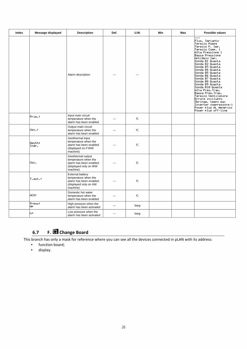
6.6 E. Alarms log
To view the active alarms and for the alarm description, refer to ch. 5.
From this menu, you can view the sequence of the alarms log by scrolling them with the arrows.
+----------------------+
|Alarms log E01| |A045 15:28 16/02/13|
|Compressor start-up| |failed |
|Z8=Min.draining pressure | |Hp: 10.6 Lp: 10.5 | |Set.: 31.0°C 32.5°C| |T.Ext.: 2.0° C | +----------------------+
The information contained in this mask is as follows:
1. the number of the logged alarm;
2. the alarm code (v. cap. dedicated to the alarms);
3. the time and date of the alarm
4. brief description of the logged alarm
5. the pressure values in bar (high Hp and low Lp) of the cooling circuit when the alarm occurred;
6. the evaporator water inlet and outlet temperature values in °C of the plate heat exchanger when the alarm
occurred (for hydronic units only);
7. the value external air temperature in °C when the alarm occurred.
Note: The maximum number of alarms that can be logged is 50; exceeded this number, newer events are overwritten
on the older ones and are therefore deleted.
The alarm can only be reset by an authorised Service Centre, from the path G.Service �f.Parameter
service�d.Def.user/changePW1 (refer to the paragraph dedicated to the Assistance menu).
Index Message displayed Description Def. U.M. Min Max Possible values
E0 Alarm code --- ---
Alarm hour --- h
Alarm minutes --- m
1
3
4
5
6
7
2
26
Index Message displayed Description Def. U.M. Min Max Possible values
Alarm description --- ---
Input main circuit temperature when the alarm has been enabled
--- °C
Output main circuit temperature when the alarm has been enabled
--- °C
Geothermal input temperature when the alarm has been enabled (displayed on if WW machine)
--- °C
Geothermal output temperature when the alarm has been enabled (displayed only on WW machine)
--- °C
External battery temperature when the alarm has been enabled (displayed only on AW machine)
--- °C
Domestic hot water temperature when the alarm has been enabled
--- °C
High pressure when the alarm has been activated
--- barg
Low pressure when the alarm has been activated --- barg
6.7 F. Change Board
This branch has only a mask for reference where you can see all the devices connected in pLAN with its address:
• function board;
• display.

27
7. ASSISTANCE MENU
7.1 G. Assistance
This chapter describes the main functions which can be accessed from the Assistance menu. Some submenu's are
accessible only with a password.
Attention: improper modification of some parameters may cause a malfunction or failure of some
components or unit.
From this menu, you can access the submenu for Assistance, divided into two parts; the first (submenu a, b, c, d ) is
not password-protected, the second (submenu e, f, g ) is password-protected and allows access to authorised Service
Centres only.
7.2 G.a. Change language
The group of masks in this branch allows the selection of one of the available languages. Press the key to
change language.
The key will display the next screen, where the language selection mask can be enabled or disabled at unit start-
up and set the display time of such mask. This function is disabled by default.
Index Message displayed Description Default U.M. Min Max Possible values
Ga01
Allows the selection of the control language
Factory setting according to
customer requirements
---
Ga02
Allows the language change mask to be disabled on start-up
YES ---
Count starting value, language change mask persistence time
60 s
7.3 G.b. Information
The branch consists of 4 masks, for reference only:
• in the first mask of the branch, you can find information concerning the application's code and its version;
• the second mask lists the information concerning the control board hardware;
• the third one lists the versions of the driver software of the electronic expansion valve;
• the fourth mask displays the inverter software versions.
Index Message displayed Description Default U.M. Min Max Possible values
Gb01
Code, version and application data --- ---
Carel manual code Bios number-version --- ---
Boot number-version --- ---
Gb02 Type of control pCO --- ---
Type of board --- ---

28
Index Message displayed Description Default U.M. Min Max Possible values
Indicates the size of the memory bank 0 of the control (KB)
2048 KB
Indicates the size of the memory bank 1 of the control (KB)
512 KB
Type of build-in display 0 ---
Application program cycles per second --- cycles/s
Application program running cycle time
--- ms
Gb04
Firmware Power+ Version --- ---
Power+ assistance version --- ---
Gb05
Boot loader Power+ Version --- ---
Software Power+ version --- ---
CRC Software Power+ --- ---
Power+ motor version --- ---
Carel Power+ ID HW --- ---
Gb07
Serial Number: Unit's serial number --- ---
Test Date: Date in which the test was carried out in the factory
--- ---
Tester Code: Code of the tester who carried out the test --- ---
7.4 G.c. Heat regulator unit
The branch is empty.
7.5 G.d. Hours worked
View the working hours of the main moving parts (pumps, compressors, fans) present in the unit and that depend on
the configuration type and number of defrost cycles. The moving parts may require periodic maintenance; in regards
to this, please refer to the installation, operation, and service manual.
Index Message displayed Description Default U.M. Min Max Possible values
Gd01
Compressor 1 hour counter --- --- 0 999999
Main circuit pump hour counter
--- --- 0 999999
Fan external battery hour counter (AW machines)
--- --- 0 999999
Gd02 Defrosting number for reverse cycle
--- --- 0 32767
IMPORTANT NOTE: from this branch on an access password is required; the password for the Assistance menu's
protected branches is 0200.

29
7.6 G.e. Config. BMS
The branch allows the parameters to be set for the unit's management in the network: communication protocols,
communication speed, network address.
Index Message displayed Description Default U.M. Min Max Possible values
Ge01
BMS protocol setting
ModBus RS485
Or protocol required by the
customer
---
BMS speed setting 38400 baud
Selection no. address for BMS
1
Or network address required by the customer
---
7.7 G.f. Assistance Parameters
The branch allows the main parameters for Assistance The limits for some parameters are established in the
Manufacturer's menu
7.7.1 Hour counter settings
����
����
From this menu the threshold for the hour counter for the different devices can be set as well as resetting the hour
counter.
Index Message displayed Description Default U.M. Min Max Possible values
Gfa01
Compressor hour counter threshold
0 --- 0 999
Pump hour counter threshold
0 --- 0 999
External fan hour counter threshold 0 --- 0 999
Gfa02
Reset compressor 1 hour counter
NO ---
Main circuit pump hour counter
NO ---
Reset external fan hour counter NO ---
Reset defrosting number hour counter
NO ---
7.7.2 Probe calibration
����
����
From this menu it is possible to enable and disable the unit's probes, as well as calibrate the probe's reading through
the calibration of an offset setting, if the values detected from one or more probes differ from the values measured
with other precision tools.
Depending on the unit type, version, and accessories, the probes will be different.

30
Index Message displayed Description Default U.M. Min Max Possible values
Gfb01
Enable/Disable B1 analogue input Air temp. exchange (external battery) Always enabled
YES ---
Offset calibration of B1 probe 0.0 °C
Value read by the probe + offset
--- °C
Enable/Disable B4 analogue input Main return water temperature Enabled only for hydronic units (only for CH and HP units)
YES (CH and HP) NO (LE and
LE/HP) ---
Offset calibration of B2 probe 0.0 °C
Value read by the probe + offset
--- °C
Gfb02
Enable/Disable B5 analogue input External power Enabled only for LE and LE/HP units
NO (CH and HP) YES (LE and
LE/HP) ---
Offset calibration of B5 probe 0.0 °C
Value read by the probe + offset
---
Enable/Disable B6 analogue input External air temperature Always enabled
YES ---
Offset calibration of B6 probe 0.0 °C
Value read by the probe + offset
--- °C
Gfb03 (mask enabled only for CH and
HP)
Enable/Disable B7 analogue input Flow temp. main circuit Enabled only for hydronic CH and HP units
YES (CH and HP) ---
Offset calibration of B5 probe 0.0 °C
Value read by the probe + offset --- °C
Gfb06 (mask enabled if EVO integrated)
Internal EVD: offset low pressure 0.0 barg
Value read by the probe + offset
--- barg
Internal EVD: offset intake temperature 0.0 °C
Value read by the probe + offset --- °C
Gfb07 (mask enabled if EVO integrated)
Internal EVD: offset probe S3 (high pressure transducer)
0.0 barg
Value read by the probe + offset --- barg
S4 probe offset calibration (T compressor discharge) 0.0 °C
Value read by the probe + offset
--- °C

31
7.7.3 Thermo regulation
����
����
From this menu the main parameters for thermo regulation of the unit can be set.
7.7.3.1 Change summer/winter selection
The Gfc01 mask is required to change summer/winter selection from the keyboard or from digital input.
Index Message displayed Description Default U.M. Min Max Possible values
Gfc01
Enable status change selection from the
keyboard or from the digital input (only HP and
LE/HP)
KEYBOARD
DIGITAL INPUT if required
---
7.7.3.2 Integrated devices to the main heat pump
The following group of masks is required to set the heat pump's integration devices (boiler or electric heaters).
If the integration devices selected are electric heaters, the activation of the heaters themselves can take place as a
function of external air temperature.
If the integration device selected is the boiler, it is possible to set its activation as a function of the external air
temperature as well as economical convenience between the boiler and the heat pump.
Index Message displayed Description Default U.M. Min Max Possible values
Gfc03
Main integration Select integration device at main (where present)
(only HP and LE/HP)
NONE
Enabled BOILER or EL. HEATER if
required
---
Type of integration
intervention at the main (only HP and LE/HP)
ENABLED PDC REPLACEMENT
Selectable only if the
integration device is the boiler
---
Selectable only if the integration device is the boiler
Gfc04 (mask enabled
if boiler enabled)
Enabling the boiler depending on the:
Integrative boiler enabling mode EXTERNAL AIR T. ---
Time delay for enabling
the boiler 5 min 0 999
Gfc05 (mask enabled
if boiler enabled +
economical convenience)
0 ---
Boiler performance setting 0 % 0 110
Select type of FUEL
Methane LPG
1 ---
Cost in Euro cents for m3
or litre of fuel 80 c€ 0 999
Resulting calculation of the temperature change between heat pump and
boiler
0.0 °C
Gfc06 (mask enabled
if boiler enabled +
economical convenience)
Day setting for the time band's consumption of
electric energy 0 ---
Allows the copy of the time bands for single days. 1 ---

32
Index Message displayed Description Default U.M. Min Max Possible values
Hour setting start band 1 0 --- 0 24
Minutes setting start time band 1
0 --- 0 60
Cost setting time band 1 0 --- 0 999
Hour setting start time
band 2 0 --- 0 24
Minute setting start time band 2 0 --- 0 60
Cost setting time band 2 0 --- 0 999
Hour setting start time
band 3 0 --- 0 24
Minute setting start time band 3 0 --- 0 60
Cost setting time band 3 0 --- 0 999
Hour setting start time
band 4 0 --- 0 24
Minute setting start time band 4
0 --- 0 60
Cost setting time band 4 0 --- 0 999
Gfc07 (mask enabled
if boiler enabled +
economical convenience)
Enable energy cost
special days 0 ---
Day setting, special day 1 0 --- 0 31
Month setting, special day 1
0 --- 0 12
Cost setting special day 1 0 --- 0 999
Day setting, special day 2 0 --- 0 31
Month setting, special day 2
0 --- 0 12
Cost setting special day 2 0 --- 0 999
Day setting, special day 3 0 --- 0 31
Month setting, special day 3
0 --- 0 12
Cost setting special day 3 0 --- 0 999
Day setting, special day 4 0 --- 0 31
Month setting, special day 4
0 --- 0 12
Cost setting special day 4 0 --- 0 999
Day setting, special day 5 0 --- 0 31
Month setting, special day 5 0 --- 0 12
Cost setting special day 5 0 --- 0 999
Day setting, special day 6 0 --- 0 31
Month setting, special day 6 0 --- 0 12
Cost setting special day 6 0 --- 0 999
Gfc08 (mask enabled
if boiler enabled)
Boiler activation setpoint for integration to the main
circuit 5.0 °C
Boiler differential
activation for integration to the main circuit
3.0 °C 0.0
Gfc09 (mask enabled
if electrical heater
enabled)
Differential with respect to the working setpoint to
enable the main circuit's electrical heater
integration.
8.0 °C 0.0

33
Index Message displayed Description Default U.M. Min Max Possible values
Differential with respect to the working setpoint to
disable the main circuit's electrical heater
integration.
5.0 --- 0.0
Time delay for enabling of
the systems electrical heaters
60 s 0 999
7.7.3.3 Compensation setpoint to the main (only in hydronic heat pump units)
In winter operation (heat pump), the hydronic circuit's input setpoint can be positively compensated depending on
the external temperature.
This function is enabled by selecting the dynamic function on the Gfc10 mask and fixing an enabling setpoint on
external temperature with a related gradient to be expressed in percentage, for example, if selecting a gradient of
50%, at a reduction of 1°C from the external temperature a setpoint flow increase of 0.5°C is attained.
The following diagram illustrates the function:
Index Message displayed Description Default U.M. Min Max Possible values
Gfc10
Temperature control output from main circuit
FIXED POINT
DYNAMIC selected if compensation
setpoint requested in the MAC
---
Temperature setpoint for
external probe compensation (B6)
7.0 °C
Compensation ramp gradient
80 % 0 100
7.7.3.4 Anti-freeze
The following group of masks are required to set the main anti-freeze parameters.
This function allows the achievement of potentially dangerous temperatures both for the system and the geothermic
probes to be avoided. Detection is carried out by the relevant temperature probes (of the geothermal circuit and
main system), and setting a setpoint and an anti-freeze differential for individual circuits.
Max set
Delta
Setpoint set
Set T-Start
Setpoint
100% 50%
T. external
34
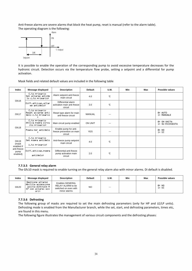
Anti-freeze alarms are severe alarms that block the heat pump, reset is manual (refer to the alarm table).
The operating diagram is the following:
It is possible to enable the operation of the corresponding pump to avoid excessive temperature decreases for the
hydronic circuit. Detection occurs via the temperature flow probe, setting a setpoint and a differential for pump
activation.
Mask fields and related default values are included in the following table
Index Message displayed Description Default U.M. Min Max Possible values
Gfc16
Alarm setpoint anti-freeze main circuit 4.0 °C
Differential alarm activation main anti-freeze
circuit 3.0 °C
Gfc17
Reset type alarm for main anti-freeze circuit
MANUAL ---
Gfc18
Main circuit pump enabled ON UNIT ---
Enable pump for anti-freeze prevention on main
circuit YES ---
Gfc19 (mask
enabled if anti-freeze
pump enabled)
Anti-freeze pump setpoint main circuit
4.0 °C
Differential anti-freeze pump activation main
circuit 2.0 °C
7.7.3.5 General relay alarm
The Gfc10 mask is required to enable turning on the general relay alarm also with minor alarms. Di default is disabled.
Index Message displayed Description Default U.M. Min Max Possible values
Gfc20
Enables GENERAL RELAY ALARM to be switched on even with
minor alarms
NO ---
7.7.3.6 Defrosting
The following group of masks are required to set the main defrosting parameters (only for HP and LE/LP units).
Defrosting mode is enabled from the Manufacturer branch, while the set, start, end defrosting parameters, times etc,
are found in this menu.
The following figure illustrates the management of various circuit components and the defrosting phases:
Alarm
ON
OFF
T. Output
Diff.
Setpoint

35
The reverse cycle occurs by default with the compressor running, if it is desired when the compressor is off, simply set
the Gfc30 mask parameter to "YES". Defrosting with compressor on, the compressor is forced to minimum speed +
delta value set in the Gfc31 mask with the maximum possible deceleration, then after a time delay it reverses to 4-
way valve and after a fixed time of 5 seconds the compressor is forced to the speed of defrosting with the acceleration
indicated (Gfc31).
Once the defrosting phase is completed, the dripping phase begins, bringing the compressor to minimum power and
forcing the fans to maximum speed. At the end of this phase, wait for the "After dripping" (Gfc32) delay, finally the 4-
way valve is reversed and the compressor is returned to the speed required for thermo regulation for HP units or by
external request for LE/HP units.
The defrosting mode set by the Manufacturer is based on the pressure. Once low pressure at the start of defrosting is
reached, the minimum time control set on the Gfc29 starts counting.
If low pressure continues for the whole duration of this minimum time, the defrosting cycle is started. Exit from the
cycle is controlled by the value read by the pressure probe and if, for some reason the setting set is not reached, the
cycle terminates as it has exceeded maximum time. This is recorded on the alarm log.
Control can manage the integration device (electrical heaters or boiler) during the defrosting phases, if enabled by the
appropriate mask (Gfc39). Integration is enabled during the whole defrosting cycle, regardless of the defrosting type
selected.
Req. defrosting Reverse Cycle
Comp.
Fans
½ Delay
Input delay
½ Delay
Delay rev. defrosting cycle
Drip time
Defrosting procedure
Inv. cycle. Defrosting Drip Inv. cycle
Req. defrosting
Reverse cycle
Speed
Comp.
Fans
Delay in
inlet
Delay after drip
Drip time
Defrosting procedure
Delay enab. compr.
Rev. cycle Defrosting Drip. Rev. cycle
5s fixed

36
Index Message displayed Description Default U.M. Min Max Possible values
Gfc21
Enables the defrosting function on external air
temperature (only HP and LE/HP)
NO ---
External temperature set for the enabling of
defrosting intervention 12.0 °C
Gfc22 (mask enabled
if defrosting temperature
selected)
Temperature set for defrosting control start (only HP and LE/HP)
2.0 °C
Temperature set for end (with control in
temperature only) 15.0 °C
Gfc27
Low pressure control setting for defrosting (only HP and LE/HP)
4.0 barg
High pressure control setting for defrosting cycle
end (only HP and LE/HP)
27.0 barg
Gfc28
Low pressure setting to force defrosting cycle (only HP and LE/HP)
3.8 barg
Time delay intervention from defrosting being
forced by low pressure (only HP and LE/HP)
5 s 0 999
Gfc29
Low pressure, minimum time control temperature,
DewPoint to begin defrosting
(only HP and LE/HP)
20 s 0 999
Gfc30
Enable compressor stop during reverse cycle for
defrosting start (only HP and LE/HP)
NO ---
Enable compressor stop during reverse cycle for
defrosting end (only HP and LE/HP)
NO ---
Gfc31 (mask enabled if compressor
stop not selected in
Gfc30 mask)
Delta for speed increase during defrosting reverse
cycle (only HP and LE/HP)
50.0 rps
Compressor speed during the defrosting phase (only HP and LE/HP)
90.0 rps 0.0 120.0
Acceleration to reach desired defrosting speed
(only HP and LE/HP) 2.0 rps/s 0.0 9.9
Gfc32 (mask enabled if compressor
stop not selected in
Gfc30 mask)
Delay between the achievement of the
compressor's minimum speed and start up of the 4-way valve for defrosting
start. (only HP and LE/HP)
5 s 0 99
Delay between the achievement of the
compressor's minimum speed and start up of the 4-way valve for defrosting
end.
20 s 0 99
Delay between the start up of the 4-way valve and
normal heat pump thermo regulation being enabled.
60 s 0 180
Gfc33
Alarm delay for envelope output during defrosting
phase (only HP and LE/HP)
180 s 0 999
Gfc34
Drip time following defrosting
(only HP and LE/HP) 15 s 6 999

37
Index Message displayed Description Default U.M. Min Max Possible values
Gfc35 (mask enabled if compressor stop selected
in Gfc30 mask)
Time delay before defrosting
(only HP and LE/HP) 30 s 6 999
Time delay after defrosting 30 s 6 999
Gfc36
Maximum defrosting cycle time
(only HP and LE/HP) 240 s 0 999
Delay between two defrosting requests 30 m 0 180
Gfc37
Parameter that enables low pressure bypass at
defrosting (only HP and LE/HP)
YES ---
Parameter that enables maximum fan speed at
defrosting end (only HP and LE/HP)
YES ---
Gfc38
High pressure control enabled in defrosting after
which the fan restarts. (only HP and LE/HP)
YES ---
High pressure control setting for fan reset 22.0 barg
Gfc39
Enable integration system ON in defrosting phase (only HP and LE/HP)
NO
Set YES if integrative
electrical heaters or boilers are
present
---
Gfc40
Enable the mask alarm at defrosting end due to
maximum time exceeded (only HP and LE/HP)
LOG ---
7.7.3.7 External battery ventilation
The following group of masks is used to set the parameters for the fan on the unit's external battery.
Adjustment is a function of evaporation pressure during the winter cycle and is a function of the condensation
pressure during the summer cycle, is of a proportional type with central setpoint and band. The setpoint is set from
the Assistance menu, while the proportional band as well as the fan's minimum and maximum speed is established by
the manufacturer.
If pressure continues to fall, the fan stops when the cut-off threshold is reached once the pressure value is back within
the adjustment band, it resumes ventilation, by adjusting the speed as a function of the new pressure detected.
If instead the pressure value continues to rise until it reaches an upper threshold, the fan is enabled at 100% to allow
the pressure value to retract within the band value.
Speed up time at fan start up is set by the Manufacturer.
Mode of operation in condensation mode (summer):

38
Operating mode in evaporation (winter only for reversible units):
Index Message displayed Description Default U.M. Min Max Possible values
Gfc41
Condensation setting 25.0 barg Lim_Min_Set_P
ress_Cond Lim_Max_Set_Pr
ess_Cond
Evaporation setting
(only HP and LE/HP) 10.0 barg Lim_Min_Set_P
ress_Evap Lim_Max_Set_Pr
ess_Evap
7.7.3.8 Overheating management and related alarms
The following mask groups are required to set the overheating setpoint, the low overheating (LowSH) alarm threshold,
low evaporation temperature (LOP), high evaporation temperature (MOP),
Overheating is governed on compressor intake and is measured via a temperature and evaporation pressure probe,
the difference between intake temperature measured and evaporation (converted by evaporation pressure)
determines the overheating measured.
The unit is equipped with an electronic expansion valve, that maintains the overheating value set in every operation.
The valve's parameters are set in the Manufacturer's menu
Index Message displayed Description Default U.M. Min Max Possible values
Gfc42
Overheating setpoint 6.0 K
LowSH: low overheating threshold
1.5 °C
LOP: low evaporation temperature threshold
-22.0 °C
MOP: high evaporation temperature threshold 22.0 °C 392.0
Fan required
100%
min
Band prop.
Press. evap. Setpoint
max
Cut-off Max. speed
Fan required
100%
min
Band prop.
Press cond. Setpoint
max
Cut-off Max. speed

39
7.7.4 Reset alarm log and change Assistance password
����
����
The Gfd01 mask resets the alarm log to change the Assistance branch password.
Index Message displayed Description Default U.M. Min Max Possible values
Gfd01
Cancels log data NO ---
New assistance password 0200 ---
7.8 G.g. Manual management
����
The branch for manual operation for: hydronic circuit pump, external fan battery, defrosting cycle, electronic
expansion valve.
Some devices/functions can work in manual mode even with the machine OFF, hence they can be used to check the
operation of single components, without switching the compressor on.
Use of the device's manual operation must occur with care, as some of the devices can be forced to
operate manually even with the unit OFF. The unit must be closed with all protections installed.
If used incorrectly, manual operation of the devices may cause malfunction or breakage and
generate significantly dangerous situations.
Once manual operation is complete, return related parameters to the default values.
Index Message displayed Description Default U.M. Min Max Possible values
Gg01 Main circuit manual pump start up AUT ---
Gg02
Manual start up of external fan battery
AUT ---
Power required to the fan in manual mode
0 %
Gg03
Defrosting cycle start up in manual mode (only LE and LE/HP)
NO ---
Gg04
Enable manual valve positioning
NO ---
Manual valve position 0 step 0 480
7.9 H. MANUFACTURER'S MENU
Access to the Manufacturer menu is password-protected and is exclusively reserved for the Manufacturer.

40
8. ALARMS
8.1 View and reset alarms
When a critical event occurs, the key will flash red: this will indicate that the unit is in alarm.
Alarms can be divided into three categories:
1. serious unit alarms, which stop the machine or some of the essential components of the unit itself (the unit
status in the main mask will be Alarm-Off);
2. non-serious alarms, which will stop one or more of the unit's functions;
3. other alarms (only reports or "warnings") which will not stop any of the unit's functions but that will warn the
user, for example when exceeding certain thresholds.
By pressing the key (brief pressure), when flashing red, the active alarms in progress are displayed scrolling
through them with the arrows, and then directly enter the alarm log (NOTE: the log is also accessible from the
appropriate menu). The alarm log is resettable only by the authorised Service Centres (please refer to the dedicated
section in the Assistance menu)
The resetting of the alarms log can be:
• automatic, reserved for non-serious alarms that are reset automatically as soon as the alarm condition has
ended;
• manual, reserved for alarms that may affect the operation of the unit and which must be reset manually after
having found the cause that triggered the alarm and after the alarm condition has ended.
By pressing the (long press) for a few seconds, the alarm in progress will be reset manually if the alarm
condition no longer exists; if the alarm is still in progress, the alarm will be triggered again even after resetting.
The manual resetting of an alarm is an operation that must be carried out only after verifying
the cause of the alarm and after having solved the problem that caused it.
8.2 Table of alarms
The following is the table with the alarms. The displayed alarms depend on the unit's configuration.
Alarm
code Message displayed Reset Meaning Action Possible solutions
A001
Alarms A001
Position: B1 Alarm probes
B1 damaged or
disconnected
Automatic
Failure of the external
battery temperature
probe
Stop the machine Check probe connection and operation.
A002
Alarms A002
Position: B2 Alarm probes
B2 damaged or
disconnected
Automatic Not used
A003
Alarms A003
Position: B3 Alarm probes
B3 damaged or
disconnected
Automatic Not used
A004
Alarms A004
Position: B4 Alarm probes
B4 damaged or
disconnected
Automatic
Failure of the water
temperature probe of the
primary input (hydronic)
Stop the machine Check probe connection and operation.
A005
Alarms A005
Position: B5 Alarm probes
B5 damaged or
disconnected
Automatic
Failure of the device for
the external control signal
(direct expansion only)
Stop the machine Check device wiring, its configuration and
operation.
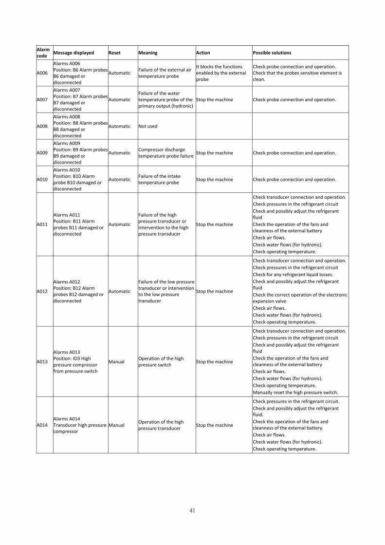
41
Alarm
code Message displayed Reset Meaning Action Possible solutions
A006
Alarms A006
Position: B6 Alarm probes
B6 damaged or
disconnected
Automatic Failure of the external air
temperature probe
It blocks the functions
enabled by the external
probe
Check probe connection and operation.
Check that the probes sensitive element is
clean.
A007
Alarms A007
Position: B7 Alarm probes
B7 damaged or
disconnected
Automatic
Failure of the water
temperature probe of the
primary output (hydronic)
Stop the machine Check probe connection and operation.
A008
Alarms A008
Position: B8 Alarm probes
B8 damaged or
disconnected
Automatic Not used
A009
Alarms A009
Position: B9 Alarm probes
B9 damaged or
disconnected
Automatic Compressor discharge
temperature probe failure Stop the machine Check probe connection and operation.
A010
Alarms A010
Position: B10 Alarm
probe B10 damaged or
disconnected
Automatic Failure of the intake
temperature probe Stop the machine Check probe connection and operation.
A011
Alarms A011
Position: B11 Alarm
probes B11 damaged or
disconnected
Automatic
Failure of the high
pressure transducer or
intervention to the high
pressure transducer
Stop the machine
Check transducer connection and operation.
Check pressures in the refrigerant circuit
Check and possibly adjust the refrigerant
fluid
Check the operation of the fans and
cleanness of the external battery
Check air flows.
Check water flows (for hydronic).
Check operating temperature.
A012
Alarms A012
Position: B12 Alarm
probes B12 damaged or
disconnected
Automatic
Failure of the low pressure
transducer or intervention
to the low pressure
transducer
Stop the machine
Check transducer connection and operation.
Check pressures in the refrigerant circuit
Check for any refrigerant liquid losses.
Check and possibly adjust the refrigerant
fluid
Check the correct operation of the electronic
expansion valve
Check air flows.
Check water flows (for hydronic).
Check operating temperature.
A013
Alarms A013
Position: ID3 High
pressure compressor
from pressure switch
Manual Operation of the high
pressure switch Stop the machine
Check transducer connection and operation.
Check pressures in the refrigerant circuit
Check and possibly adjust the refrigerant
fluid
Check the operation of the fans and
cleanness of the external battery
Check air flows.
Check water flows (for hydronic).
Check operating temperature.
Manually reset the high pressure switch.
A014
Alarms A014
Transducer high pressure
compressor
Manual Operation of the high
pressure transducer Stop the machine
Check pressures in the refrigerant circuit.
Check and possibly adjust the refrigerant
fluid.
Check the operation of the fans and
cleanness of the external battery.
Check air flows.
Check water flows (for hydronic).
Check operating temperature.

42
Alarm
code Message displayed Reset Meaning Action Possible solutions
A015
Alarms A015
Transducer low pressure
compressor
Automatic Operation of the low
pressure transducer Stop the machine
Check pressures in the refrigerant circuit.
Check for any refrigerant liquid losses and
refill to original level.
Check the correct operation of the electronic
expansion valve.
Check air flows.
Check water flows (for hydronic).
Check operating temperature.
A016
Alarms A016
Unit stopped safety
alarm!
Manual Main alarm coming from
external signal Stop the machine Check the alarm cause.
A020
Alarms A020
Position: ID4 Thermal
pump
Manual
Protection of the pump's
electric motor (only for
pump unit)
Stop the machine Check the pump's electric motor protection.
Check that the pump is not blocked.
A021
Alarms A021
Position: ID10 Utility
main water circuit meter
Manual No air flow (only for
hydronic units) Stop the machine
Check that there is water in the primary
circuit.
Check the flow meter's operation and its
electrical connections.
A022
Alarms A022
Position: ID7 Boiler
alarm/add. system heater
Automatic
The system's additional
heater is in alarm
(only if it is integrative
source enabled)
Interrupts boiler/electrical
heater operation, main
circuit integration
Check the cause of the alarm from the
integrative source
A023 Alarm A023 Position: ID1
fan circuit breaker Manual
Fan motor thermal
protection alarm Stop the machine
Check the operation of the fan wiring.
Check the operation of the thermal
protection wiring.
A024
Alarms A024
Reached the
compressor's working
hours threshold
Manual
The threshold of hours
worked for the
compressor has been
reached
Only signal Replace the component.
Reset the hour counter.
A025
Alarms A025
Reached the primary
pump's working hours
threshold
Manual
The threshold of hours
worked for the primary
pump has been reached
Only signal Replace the component.
Reset the hour counter.
A026
Alarms A026
Reached the fan battery's
working hours threshold
Manual
The threshold of hours
worked for the fan battery
has been reached
Only signal Replace the component.
Reset the hour counter.
A027
Alarms A027
System exchanger anti-
freeze
Manual
On reaching the anti-
freeze threshold
temperature limit of the
main exchanger (only
hydronic units)
Stop the machine
Check water flow.
Check setpoint.
Check the correct operation of the electronic
expansion valve.
Clean and replace the exchanger.
A028
Alarms A028
Maximum time
defrosting output
Automatic
Defrosting ended due to
the reaching of the
maximum time instead of
the reaching of the set
condition
Only signal None.
A029 Alarms A029
EEPROM Alarm Manual Memory board alarm Stop the machine Check the control board.
A030
Alarms A030
Position: Alarm probe S1
damaged or disconnected
Manual Operation of the low
pressure transducer Stop the machine
Check pressures in the refrigerant circuit.
Check for any refrigerant liquid losses and
refill.
Check the correct operation of the electronic
expansion valve.
Check air flows.
Check water flows (for hydronic).
Check operating temperature.

43
Alarm
code Message displayed Reset Meaning Action Possible solutions
A031
Alarms A031
Position: Alarm probes S2
damaged or disconnected
Manual
Failure of the intake
temperature probe or
intake temperature below
the minimum limit
Stop the machine
Check probe connection and its operation.
Check pressures in the refrigerant circuit.
Check the suction temperature.
Check for any refrigerant liquid losses and
refill.
Check the correct operation of the electronic
expansion valve.
Check air flows.
Check water flows (for hydronic).
Check operating temperature.
A032
Alarms A032
Position: Alarm probes S3
damaged or disconnected
Manual Operation of the high
pressure transducer Stop the machine
Check transducer connection and its
operation.
Check pressures in the refrigerant circuit.
Check and possibly adjust the refrigerant
fluid level.
Check the operation of the fans and
cleanness of the external battery.
Check operating temperature.
Check air flows.
Check water flows (for hydronic).
A033
Alarms A033
Position: Alarm probes S4
damaged or disconnected
Manual
Failure of the drain
temperature probe or
drain temperature above
the maximum limit
Stop the machine
Check probe connection and its operation.
Check pressures in the refrigerant circuit.
Check overheating.
Check and possibly adjust the refrigerant
fluid level
Check the operation of the fans and
cleanness of the external battery.
Check air flows.
Check water flows (for hydronic).
Check operating temperature.
A034 Alarms A034
Valve motor error Manual
Electronic expansion valve
motor error Stop the machine Check the valve's motor and its wiring.
A035 Alarms A035
Low overheating (LowSH) Manual
Intake overheating below
the minimum limit Stop the machine
Check pressures in the refrigerant circuit.
Check the suction temperature.
Check for any refrigerant liquid losses and
refill.
Check the correct operation of the electronic
expansion valve.
Check air flows.
Check water flows (for hydronic).
Check operating temperature.
A036 Alarms A036
Low intake temperature Manual
Intake temperature below
the minimum limit Stop the machine
Check pressures in the refrigerant circuit.
Check the intake temperature.
Check for any refrigerant liquid losses and
refill.
Check the correct operation of the electronic
expansion valve.
Check air flows.
Check water flows (for hydronic).
Check operating temperature.
A037
Alarms A037
Low evaporation
temperature (LOP)
Manual Evaporation temperature
below minimum limit Stop the machine
Check pressures in the refrigerant circuit.
Check the intake temperature.
Check for any refrigerant liquid losses and
refill.
Check the correct operation of the electronic
expansion valve.
Check air flows.
Check water flows (for hydronic).
Check operating temperature.

44
Alarm
code Message displayed Reset Meaning Action Possible solutions
A038
Alarms A038
High evaporation
temperature (MOP)
Manual Evaporation temperature
above the maximum limit Stop the machine
Check pressures in the refrigerant circuit.
Check the intake temperature.
Check for any refrigerant liquid losses and
refill.
Check the correct operation of the electronic
expansion valve
Check air flows.
Check water flows (for hydronic).
Check operating temperature.
A039
Alarms A039
High condensation
temperature
Manual Condensing temperature
above the maximum limit Stop the machine
Check pressures in the refrigerant circuit.
Check the condensation temperature.
Check and possibly adjust the refrigerant
fluid level.
Check the operation of the fans and
cleanness of the external battery.
Check air flows.
Check water flows (for hydronic).
Check operating temperature.
A040 Alarms A040
EEV driver offline Manual
EEV driver alarm (only if
present) Stop the machine Not present.
A041
Alarms A041
Power+ n°1
Offline device
Manual
Power+ inverter is not
communicating with the
control (it also appears
when the high pressure
switch is triggered)
Stop the machine
Check that the high pressure switch is
triggered and possibly reset it after checking
the causes of the intervention.
Check the connection between the inverter
and the control board.
A042 Alarms A042
Power+ n°1 Manual Power+ inverter alarm Stop the machine Refer to the table below for alarm codes.
A043
Alarms A043
Inverter type not
compatible (Power+ type
only)
Automatic Inverter not compatible
with the control Stop the machine
Check the inverter's wiring.
Check the connection between the inverter
and the control board.
A044 Alarms A044
Envelope Zone alarm: Manual
The compressor is working
outside the envelope Stop the machine
Check pressures in the refrigerant circuit.
Check the condensation and evaporation
temperatures.
Check and possibly adjust the refrigerant
fluid level.
Check air flows.
Check water flows (for hydronic).
Check operating temperature.
A045
Alarms A045
Compressor start-up
failed (attempts: / max.: )
Automatic, it
becomes
manual after
5 attempts
The compressor failed
start-up
Only signal;
Machine is stopped after
5 failed attempts
Check the compressor's rotation direction.
Check pressures in the refrigerant circuit.
Check the condensation and evaporation
temperatures.
Check and possibly adjust the refrigerant
fluid level.
Check operating temperature.
A046
Alarms A046
High discharge gas
temperature
Manual
Exceeded maximum
compressor discharge gas
temperature
Stop the machine
Check probe connection and its operation.
Check pressures in the refrigerant circuit
Check and possibly adjust the refrigerant
fluid level.
Check the condensation temperature.
Check overheating.
Check the operation of the fans and
cleanness of the external battery.
Check air flows.
Check water flows (for hydronic).
Check operating temperature.
A047
Alarms A047
Low pressure differential
(insuff. lubrication)
Manual Low Δp for the
compressor's lubrication Stop the machine
Check pressures in the refrigerant circuit.
Check and possibly adjust the refrigerant
fluid level.
Check operating temperature.
A100
Alarms A100
Press ENTER for the
alarms LOG
Manual Access to the alarms log

45
The table below shows the description of the alarms codes of the Power+ inverter, viewable from the alarm A042
mask. For further information, refer to the inverter Power+ manual.
Alarm code A042 Description Possible solutions
0: No error
1: Overcurrent
The drive has detected that the current
delivered is too high for:
- sudden heavy load increase;
- acceleration is too high;
- Unsuitable motor.
Check the operating conditions and the
parameters set.
2: Motor overload The current delivered has exceeded nominal
current over the maximum time allowed. Check the operating conditions.
3: Overvoltage
The intermediate circuit tension in DC has
exceeded limits established for:
- Deceleration too high;
- high surge peaks on the mains power supply.
Check the power supply voltage.
4: Undervoltage
The intermediate circuit tension in DC under the
limits established for:
- power supply voltage insufficient;
- internal drive failure.
In the event of momentary power
supply interruption
reset the alarms and
restart the drive. Check the power
supply voltage.
5: Over temperature The drive's internal temperature has exceeded
the maximum allowed level
Check the correct amount and flow of
cooling air. Check that there is no dust
or dirt in the heat
dissipater.
Check room temperature and operating
conditions.
6: Under-heating The drive's internal temperature has exceeded
the minimum level allowed. Check room temperature.
7: HW overcurrent
The drive has detected that the current
delivered is too high for:
- sudden heavy load increase;
- short circuit of the motor cables;
- Unsuitable motor.
Check the operating conditions and the
parameters set.
Check motor cabling.
8: Motor over-heating The temperature detected by the PTC thermistor
corresponds to electrical heater of > 600 ohm.
Reduce motor load.
Check motor cooling.
9: Drive failure Generic inverter failure
Switch the unit off and on again.
If the problem persists, check the serial
connection and possibly replace the
inverter.
10: Cpu Error Loss of stored data
Switch the unit off and on again.
If the problem persists, check the serial
connection and possibly replace the
inverter.
11: Default parameters Parameter error
Switch the unit off and on again.
If the problem persists, check the serial
connection and possibly replace the
inverter.
12: DC bus ripple voltage No input phase Check the inverter's power input
phases
13: Serial
communication timeout
Communication error between the inverter and
control
Check serial connection.
Switch the unit off and on again.

46
14: Thermistor error Internal Thermistor failure
Switch the unit off and on again.
If the problem persists, check the serial
connection and possibly replace the
inverter.
15: Autotuning Error
Error in inverter autotuning
Switch the unit off and on again.
If the problem persists, check the serial
connection and possibly replace the
inverter.
16: Drive disabled
Inverter disabled as a result of opening safety
torque off entrance (for eg. following inspection
of the high pressure switch)
Check the opening of the safety torque
off entrance cause (eg. triggering of the
high pressure switch) and restore
17: Motor phase missing A phase between the compressor's motor and
inverter is missing Check the electrical connections.
18: Fan failure Failure of the inverter cooling fan Check and possibly replace the fan
19: Motor stalled BLDC compressor motor stalled Switch the unit off and on again.
20: PFC module failure Power factor correction module failure
Switch the unit on and off again and
check that the parameters are correct.
Check motor load.
21: alarm code 21 Reserved
22: PFC undervoltage Reserved
23: STO reading error Reserved
24: STO reading error Reserved
25: alarm code 25 Reserved
26: alarm code 26 Reserved
27: alarm code 27 Reserved
28: alarm code 28 Reserved
29: alarm code 29 Reserved
30: alarm code 30 Reserved

47
10312450002_ SERVICE CONTROL MANUAL Smart HP_08-08-2013