Embed Size (px)
Citation preview

102E-OM1109-01
OPERATION MANUAL
MINI-CRAWLER CRANE
Serial No. P00976 and up
Unsafe use of this machine may cause serious injury or death. Operators must read this manual before operating this machine. This manual should be kept near the machine for reference and periodically reviewed by all personnel who will come into contact with it.
NOTICE
MAEDA has Operation Manual written in some other languages. If a foreign language manual is necessary, contact your local distributor for availability.


CONTENTS
ITEM Page
INTRODUCTION 1- 1
1. INTRODUCTION 1- 2
2.FOR SAFE USE OF MACHINE 1- 3
3. MACHINE OVERVIEW 1- 4
3.1 SPECIFIED OPERATIONS 1- 4
3.2 MACHINE CONFIGURATION 1- 4
3.3 MACHINE FUNCTIONS 1- 5
4. QUALIFICATION FOR OPERATION 1- 6
4.1 QUALIFICATION FOR CRANE OPERATION 1- 6
5. TERMINOLOGY 1- 7
5.1 DEFINITIONS OF TERMS 1- 7
5.2 DIAGRAM OF WORKING RADIUS AND LIFTING HEIGHT 1- 8
5.3 RATED TOTAL LOAD CHART 1- 9
5.4 ANGLE INDICATOR 1-13
SAFETY 2- 1
1. BASIC PRECAUTIONS 2- 2
2. DRIVING RELATED PRECAUTIONS 2- 7
2.1 BEFORE STARTING ENGINE 2- 7
2.2 AFTER STARTING ENGINE 2- 8
2.3 WORKING WITH CRANE 2-12
3. TRANSPORT PRECAUTIONS 2-21
4. BATTERY HANDLING PRECAUTIONS 2-23
5. MAINTENANCE PRECAUTIONS 2-25
5.1 PRECAUTIONS BEFORE MAINTENANCE 2-25
5.2 PRECAUTIONS DURING MAINTENANCE 2-27
6. SAFETY LABEL LOCATIONS 2-32
OPERATION 3- 1
1. MACHINE EACH SECTION 3- 2
1.1 MACHINE EACH UNIT 3- 2
1.2 TRAVELLING AND CRANE OPERATION UNITS 3- 3
1.2.1 DESCRIPTION OF EACH LEVER 3- 4
1.2.2 DESCRIPTION OF EACH SWITCH 3- 6
1.2.3 DESCRIPTION OF EACH METER AND LAMP 3- 7
1.3 CRANE OPERATION UNIT 3- 9
1.3.1 DESCRIPTION OF EACH LEVER 3-10
1.3.2 DESCRIPTION OF EACH SWITCH 3-11
1.4 OUTRIGGER SAFETY DEVICES 3-14
1.4.1 FUNCTIONS OF OUTRIGGER SAFETY DEVICES 3-14
1.4.2 NAMES AND DESCRIPTIONS OF OUTRIGGER DISPLAY 3-15
1.4.3 OUTRIGGER UN-SET WARNING LAMP 3-16
1.5 MOMENT LIMITER (OVERLOAD DETECTOR) 3-17
1.5.1 MOMENT LIMITER CONFIGURATION 3-17
1.5.2 FUNCTION OF MOMENT LIMITER 3-18
0-1
ITEM Page
1.5.3 MOMENT LIMITER OPERATIONS 3-19
1.5.4 NAMES OF MOMENT LIMITER DISPLAY UNIT 3-21
1.5.5 MOMENT LIMITER FUNCTIONS 3-28
1.5.6 MOMENT LIMITER STARTING STATUS 3-31
1.5.7 MOMENT LIMITER WORKING ENVELOPE SETTING 3-31
1.5.8 EMERGENCY STOP CANCEL SWITCH 3-32
1.5.9 MOMENT LIMITER ERROR CAUSES AND ACTIONS TO BE TAKEN 3-33
1.6 MACHINERY COVER 3-34
1.7 OVER HOIST DETECTOR 3-35
2. OPERATIONS 3-36
2.1 CHECKING BEFORE OPERATIONS 3-36
2.1.1 VISIBLE CHECKS 3-36 2.1.2 CHECKING BEFORE STARTING ENGINE 3-39
2.1.3 CHECKING AFTER STARTING ENGINE 3-50
2.2 STARTING ENGINE 3-58
2.2.1 NORMAL ENGINE START 3-58
2.2.2 STARTING ENGINE IN COLD WEATHER 3-59
2.2.3 STARTING THE ENGINE WITH AUXILIARY STARTER SWITCH 3-60
2.3 OPERATIONS AND CHECKS AFTER STARTING ENGINE 3-61
2.4 BREAKING-IN MACHINE 3-63
2.5 MACHINE TRAVELLING POSTURE 3-63
2.6 STARTING MOVING MACHINE 3-64
2.7 CHANGING DIRECTION OF THE MACHINE 3-65
2.8 STOPPING/PARKING THE MACHINE 3-66
2.9 STOPPING ENGINE 3-67
2.10 INSPECTION AFTER STOPPING ENGINE 3-67
2.11 CAUTIONS IN DRIVING 3-68
2.12 OUTRIGGER SETUP OPERATION 3-70
2.12.1 NAME OF OUTRIGGER COMPONENTS 3-72
2.12.2 OUTRIGGER SETTING OPERATION 3-72
2.13 CAUTIONS BEFORE CRANE OPERATION 3-76
2.14 OPERATIONS BEFORE CRANE OPERATIONS 3-77 2.15 CRANE OPERATION POSTURE 3-78
2.16 HOOK RAISING/LOWERING OPERATION 3-79
2.17 BOOM DERRICKING OPERATION 3-79
2.18 BOOM TELESCOPING OPERATION 3-80
2.19 SLEWING OPERATION 3-81 2.20 ACCELERATION OPERATION 3-81
2.21 CRANE STOWING OPERATION 3-82
2.22 OUTRIGGER STOWING OPERATION 3-84
2.23 DOS AND DON’TS DURING CRANE OPERATIONS 3-87
3. HANDLING RUBBER TRACKS 3-89
3.1 GOOD USE 3-89
3.2 WARRANTY 3-89
3.3 DOS AND DON’TS 3-90
3.4 CAUTIONS IN USING RUBBER TRACKS 3-91
0-2

ITEM Page
4. HANDLING WIRE ROPES 3-93
4.1 BENCH MARK FOR REPLACING WIRE ROPES 3-93
4.2 What TO DO WITH TWISTED WINCH WIRE ROPE 3-94
5. TRANSPORTATION 3-95
5.1 LOADING/UNLOADING 3-95
5.2 HOISTING MACHINE 3-96
5.3 CAUTIONS IN LOADING MACHINE 3-97
5.4 CAUTIONS DURING TRANSPORTATION 3-97
6. HANDLING IN COLD WEATHER 3-98
6.1 PREPARING FOR LOW TEMPERATURE 3-98
7. LONG-TERM STORAGE 3-100 7.1 BEFORE STORING MACHINE 3-100
7.2 DURING STORAGE 3-100
7.3 AFTER STORAGE 3-100
8. HANDLING BATTERY 3-101
8.1 CAUTIONS IN HANDLING BATTERY 3-101
8.2 REMOVING/INSTALLING BATTERY 3-102 8.3 CAUTIONS IN CHARGING BATTERY 3-103
8.4 STARTING ENGINE WITH BOOSTER CABLE 3-104
9. TROUBLESHOOTING 3-106
9.1 ELECTRICAL COMPONENTS 3-106
9.2 MACHINE BODY 3-106
9.3 ENGINE 3-107
INSPECTION AND MAINTENANCE 4- 1
1. PRECAUTIONS FOR MAINTENANCE 4- 2
2. BASIC MAINTENANCE 4- 4 3. LEGAL INSPECTION 4- 6
4. CONSUMABLES 4- 6
5. LUBRICATING OIL 4- 7
5.1 USE OF LUBRICATING OIL ACCORDING TO TEMPERATURES 4- 7
6. ACCESSORY TOOLS AND STANDARD TIGHTENING TORQUE 4- 8 6.1 ACCESSORY TOOLS 4- 8
6.2 STANDARD TIGHTENING TORQUE LIST 4- 8
7. INSPECTION AND MAINTENANCE LIST 4-10
8. MAINTENANCE PROCEDURES 4-12
8.1 INITIAL 10 HOUR MAINTENANCE 4-12
8.2 INITIAL 50 HOUR MAINTENANCE 4-12
8.3 INITIAL 250 HOUR MAINTENANCE 4-12
8.4 CHECKING BEFORE OPERATION 4-12 8.5 IRREGULAR MAINTENANCE 4-13
8.6 MAINTENANCE EVERY 30 HOURS 4-22
8.7 MAINTENANCE EVERY 50 HOURS 4-24
8.8 MAINTENANCE EVERY 100 HOURS 4-27
8.9 MAINTENANCE EVERY 250 HOURS 4-28
8.10 MAINTENANCE EVERY 500 HOURS 4-30
8.11 MAINTENANCE EVERY 1000 HOURS 4-35
8.12 MAINTENANCE EVERY 2000 HOURS 4-46
0-3

ITEM Page
SPECIFICATIONS 5- 1
1. SPECIFICATIONS 5- 2
2. SPECIFICATION DIMENSIONAL DRAWING 5- 3
3. DIMENSIONAL DRAWING OF OUTRIGGER WIDTH 5- 4
4. RATED TOTAL LOAD CHART 5- 5
3.1 RATED TOTAL LOAD CHART FOR 4 FALLS 5- 5
3.2 RATED TOTAL LOAD CHART FOR 2 FALLS 5- 6
3.3 RATED TOTAL LOAD CHART FOR SINGLE FALL 5- 7
5. WORKING RADIUS AND LIFTING HEIGHT 5- 8
REMOTE CONTROL 6- 1
1. OUTLINE OF REMOTE CONTROLLER 6- 2
1.1 FEATURE 6- 2
1.2 CONFIGURATION 6- 2
1.3 FUNCTIONS OF REMOTE CONTROL SYSTEM 6- 3
2. SAFETY PRECAUTIONS 6- 4
2.1 FOR SAFETY OPERATIONS 6- 4
2.2 PRECAUTIONS FOR CRANE OPERATION 6- 6
2.2.1 PRIOR TO STARTING ENGINE 6- 6
2.2.2 SUBSEQUENT TO STARTING ENGINE 6- 7
2.2.3 TERMINATING THE OPERATION 6- 7
3. LOCATIONS OF SAFETY LABELS 6- 8
4. COMPONENTS OF THE TRANSMITTER 6-10
5. COMPONENTS OF THE RECEIVER 6-15
5.1 COMPONENTS OF THE RECEIVER 6-15
5.2 FUSE IN THE RECEIVER 6-17
6. MODE SETTING OF THE TRANSMITTER 6-19
6.1 A MODE 6-19
6.1.1 OPENING A MODE SCREEN 6-19 6.1.2 MESSAGES IN THE A MODE SCREEN 6-19
6.1.3 AN EXAMPLE FOR SETTING IN THE A MODE 6-23
6.2 PROCEDURE IN THE OPERATION MODE 6-24
6.2.1 CALL OUT CRANE MODE 6-24
6.2.2 CALL OUT OUTRIGGER MODE 6-25
7. CHECKING BEFORE OPERATION 6-27
7.1 CHECKING BEFORE STARTING ENGINE 6-27
7.1.1 CHECKING BEFORE TURNING ON THE TRANSMITTER 6-27
7.1.2 CHECKING AFTER TURNING ON THE TRANSMITTER 6-28
7.1.3 CHECKING RECEIVER 6-32
7.2 CHECKING AFTER STARTING ENGINE 6-33
7.2.1 VERIFICATION FOR THE ENGINE START AND STOP 6-33
7.2.2 CHECKING “OUTRIGGER MODE” OPERATION 6-34
7.2.3 CHECKING “CRANE MODE” OPERATION 6-36
0-4

ITEM Page
8. OPERATION 6-38
8.1 CAUTIONS BEFORE OPERATION 6-38
8.2 OPERATION IN OUTRIGGER MODE 6-39
8.2.1 OUTRIGGER SETTING 6-40
8.2.2 OUTRIGGER STOWING 6-41
8.3 OPERATION IN CRANE MODE 6-42 8.3.1 SLEWING OPERATION 6-43 8.3.2 BOOM TELESCOPING 6-43
8.3.3 HOOK RAISING AND LOWERING 6-44
8.3.4 BOOM DERRICKING 6-44
8.3.5 SET-UP AND CANCEL MICRO SPEED 6-45
8.3.6 ENGINE STOP AND EMERGENCY STOP PROCEDURE 6-47
8.3.7 ENGINE START AND RESET PROCEDURE 6-47
8.4 CHECKING AFTER CRANE OPERATION 6-48
9. TROUBLE SHOOTING 6-49
9.1 BEFORE TROUBLE SHOOTING 6-49
9.2 ERRORS IN THE REMOTE CONTROL DEVICES 6-50
10.SYSTEM SPECIFICATIONS 6-52
ENGINE AND ELECTRIC MOTOR SPECIFICATIONS 7- 1
1. PRECAUTIONS (FOR ENGINE AND ELECTRIC MOTOR SPECIFICATION) 7- 2 2. SAFETY LABEL LOCATIONS 7- 3
3. MACHINE EACH SECTION 7- 5
3.1 TRAVELLING UNIT 7- 5
3.2 POWER UNIT 7- 8
3.3 POWER SUPPLY BOX 7- 8
3.4 INVERTER UNIT 7- 9
4. OPERATION 7-12 4.1 CHECKING BEFORE OPERATION 7-12
4.1.1 CHECKING BEFORE STARTING ELECTRIC MOTOR (VISIBLE CHECKS) 7-12
4.1.2 CHECKING BEFORE STARTING ELECTRIC MOTOR 7-12
4.1.3 CHECKING AFTER STARTING ELECTRIC MOTOR 7-12 4.2 POWER SUPPLY CONNECTION 7-13
4.3 OPERATION AND CHECKING AFTER POWER CONNECTION 7-15
4.4 MACHINE OPERATION 7-17
4.5 MACHINE STOP AND CHECKS AFTER STOPPING MACHINE 7-17
4.6 POWER SUPPLY SEPARATION 7-18 5. LONG-TERM STORAGE 7-19
6. ELECTRIC MOTOR TROUBLESHOOTING 7-20
7. PRINCIPLE SPECIFICATION LIST 7-21
8. SPECIFICATION DIMENSIONAL DRAWING 7-22
9. DIMENSIONAL DRAWING OF OUTRIGGER WIDTH 7-23
0-5

0-6
ITEM Page
SEARCHER HOOK 8- 1
1. SAFETY DECAL LOCATIONS 8- 2
2. SEARCHER HOOK EACH SECTION 8- 4
3. MOMENT LIMITER DISPLAY UNIT 8- 5
4. OPERATION 8- 7
5. INSPECTION AND MAINTENANCE 8-9
5.1 LEGAL INSPECTION 8-9
5.2 CONSUMABLES 8-9 5.3 INSPECTION AND MAINTENANCE LIST 8-9
5.4 MAINTENANCE PROCEDURES 8-10
5.4.1 INSPECTION OF BEFORE OPERATION 8-10
6. WORKING RANGE AND RATED TOTAL LOAD 8-12
6.1 WORKING RANGE DIAGRAM FOR SEARCHER HOOK 8-12
6.2 RATED TOTAL LOAD CHART FOR SEARCHER HOOK 8-13

INTRODUCTION
1. INTRODUCTION 1- 2
2. FOR SAFE USE OF MACHINE 1- 3
3. MACHINE OVERVIEW 1- 4
4. QUALIFICATION FOR OPERATION 1- 6
5. TERMINOLOGY 1- 7
1-1
1. INTRODUCTION Thank you for purchasing our Mini Crawler Crane “MC285C-2”. This manual is a guidebook for safe and effective use of this machine. This manual describes the procedures for proper operation and maintenance of the machine. Warnings and precautions defined in this manual shall be observed for safety. Many accidents are caused when safety precautions for the operation, inspection, and maintenance are not observed. Be sure to read this manual and understand the procedures for machine operation, inspection, and maintenance thoroughly before performing operation of this machine. Failure to observe the basic precautions defined in this manual may lead to accidents.
Failure to use this machine properly can lead to serious personal injury or death. Operators and maintenance personnel must always read this manual prior to operation or maintenance of this machine. Save this manual at a designated place for reference when necessary. All personnel who work on this machine are to carry out periodic reference. • Only those who have thorough understanding of the fundamental procedures
provided in this manual are qualified to perform machine operation. • Keep this manual handy for reference when necessary. • Should you lose or damage this manual, contact Maeda or our sales service
agency immediately to order a replacement. • This manual should always accompany this machine upon transfer of the machine
to the next owner. • This manual has adopted data that was available at the time of the creation of the
manual. The contents of this manual, including maintenance specifications, tightening torque, pressure, measuring method, adjustment value, and illustrations, are subject to change upon unremitting refinement of the machine, without notice. Machine maintenance may be susceptible to revisions. Always obtain the latest information from Maeda or our sales service agency before performing maintenance of this machine.
For safety instructions, see “2. For Safe Use of Machine” on page 1-3 and “Safety” on page 2-1.
1-2
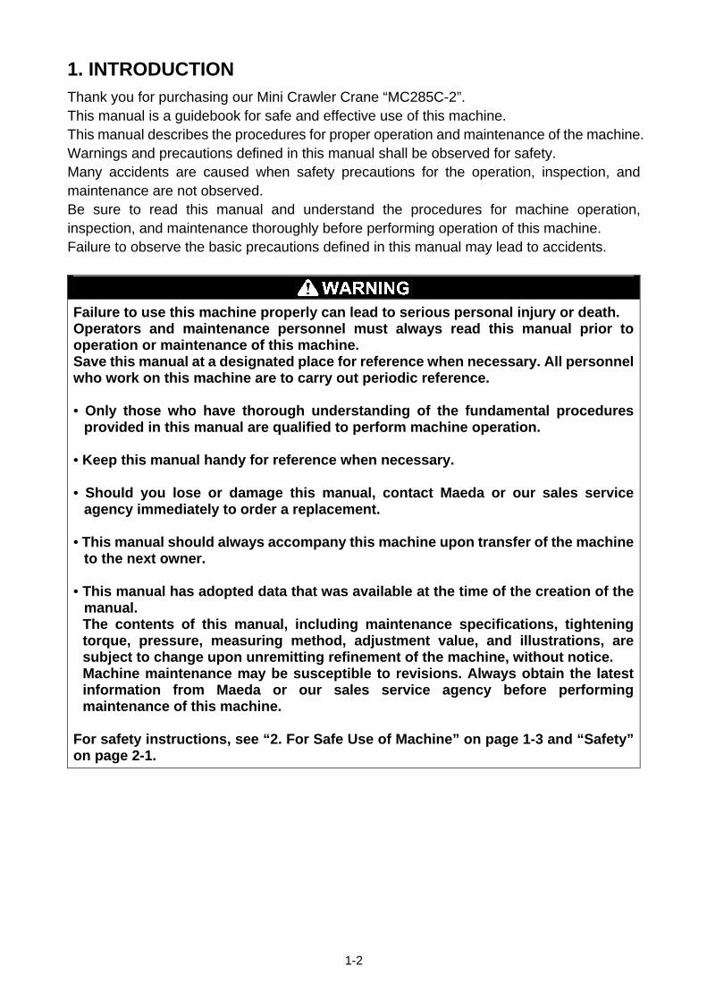
2. FOR SAFE USE OF MACHINE This manual classifies the risks into the following three categories to present the details of the safety
labels in an easy-to-understand manner.
This denotes that there is an imminent hazard which will cause serious
personal injury or death.
The method of hazard circumvention is stated.
This denotes that there is a hazard which can cause serious personal injury
or death.
The method of hazard circumvention is stated.
This denotes that there is a potential hazard which may cause minor or
moderate personal injury or serious damage to this machine.
The method of hazard circumvention is stated.
This manual also provides the following to indicate what must be observed for the sake of the machine
and what will be of help.
CAUTION This denotes that failure to handle the machine properly may damage the
machine or shorten its life.
1-3
This denotes helpful information.
NOTES
The operations, inspections, maintenance and safety precautions for this machine that are outlined in this
manual are relevant for specified tasks.
Every circumstance incidental to use of this machine is unforeseeable, and therefore, cautions given in
this manual and on this machine do not necessarily cover every safety-related issue.
Necessary safety actions should be taken under your responsibility, if operation, inspection, and
maintenance in a situation that is not described in this manual are performed.
Even in the above case, never attempt work and operations that this manual prohibits you to do.
3. MACHINE OVERVIEW
3.1 SPECIFIED OPERATIONS
This machine is to be used for operation listed below.
• Crane operation
This machine is a mobile crane with a rubber track travelling dolly (carrier) mounted with a boom crane.
This self-propelled crane is capable of moving (travelling) in the worksite and craning an object weighing
within the rated total load.
This is also a remote-controlled crane.
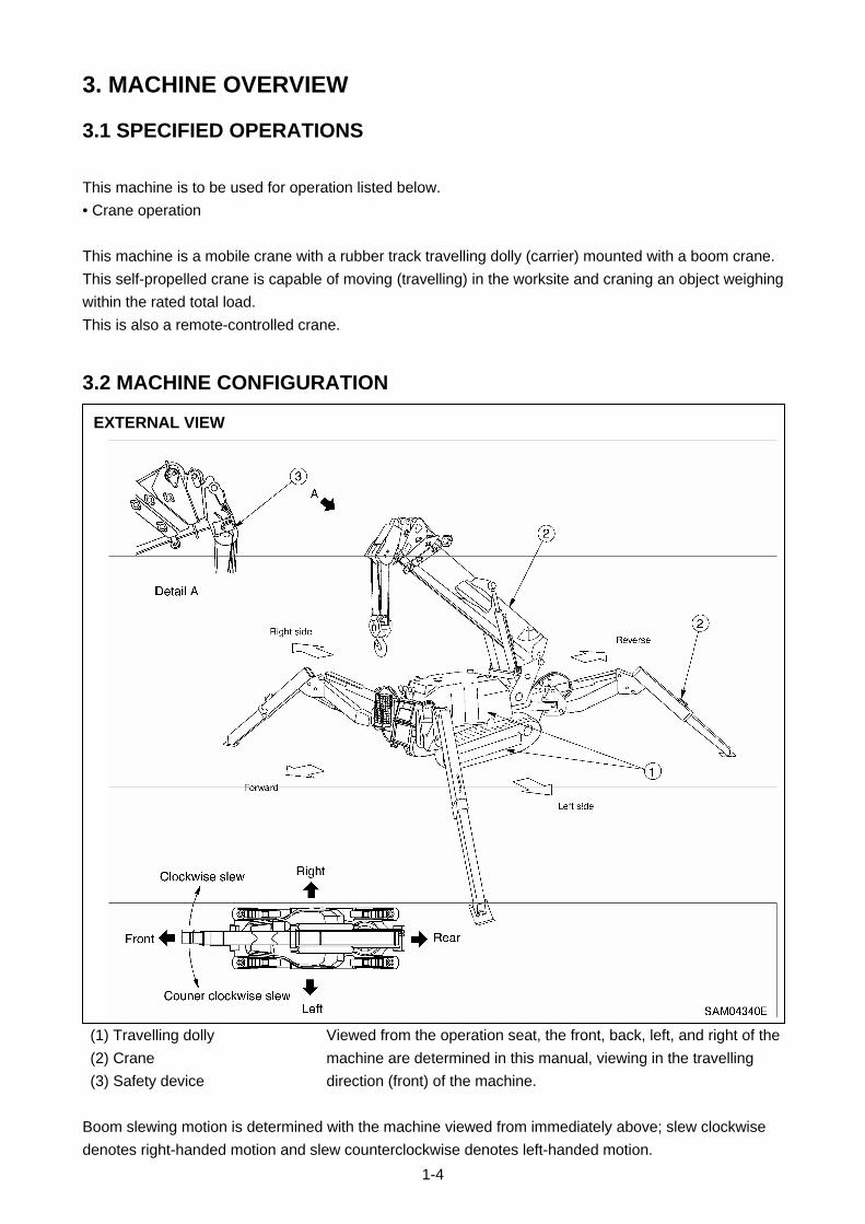
3.2 MACHINE CONFIGURATION
(1) Travelling dolly
(2) Crane
(3) Safety device
Viewed from the operation seat, the front, back, left, and right of the
machine are determined in this manual, viewing in the travelling
direction (front) of the machine.
EXTERNAL VIEW
Boom slewing motion is determined with the machine viewed from immediately above; slew clockwise
denotes right-handed motion and slew counterclockwise denotes left-handed motion.
1-4

This machine is composed of the units listed below.
[1] TRAVELLING DOLLY
This is composed of a travelling gear, engine, travelling operation unit, and crane operation unit.
[2] CRANE
This is composed of a telescoping system, derrick system, hook block, winch system, and outrigger
system.
[3] SAFETY DEVICE
This is composed of the following parts and devices: Over hoist detector / automatic stop device,
three-winding stop alarm / automatic stop device, load indicator, hydraulic safety valve, hydraulic
automatic locking device, slinging rope detachment protector, alarm buzzer, audio alarm, level, crane
tip-over alarm (an alarm issued in the event of the crane operation at 3-degree inclination and travelling at
15-degree inclination), travelling lever lock, travelling/crane/outrigger selector switch (designed to prevent
the machine from craning at travelling), outrigger safety device (outrigger interlock and crane interlock),
moment limiter (working envelope limited), working status lamp, outrigger non-installation warning lamp.
3.3 MACHINE FUNCTIONS
[1] TRAVELLING DOLLY
• This is a compact machine designed to keep the overall width between the crane and outrigger
minimized with them housed (in travelling position).
This compact design is ideal for work in confined areas.
• Two-travelling lever operation enables not only direction changes among forward, backward, right, and
left, but also pivot turn and spin turn.
[2] CRANE
• An automatic slide outrigger is embedded in the crane to permit outrigger extension and grounding from
the operation seat.
• Through the combined use of telescoping, derricking, and slewing besides winch system operation, the
crane is capable of raising or lowering the hook block and moving an object weighing within the rated
total load to a designated position within the confines of the working envelope.
• Remote-control units allow remote outrigger setting and remote crane operation.
1-5

4. QUALIFICATION FOR OPERATION
• A high incidence of occupational accidents in crane operation has been reported.
Be aware that experienced engineers are also no exception. • Warnings and precautions defined in this manual shall be observed for safety assurance
during operation of the machine.
4.1 QUALIFICATION FOR CRANE OPERATION
Only personnel that have obtained the license stipulated by laws and regulations applicable to the place of
use are qualified to operate this machine.
Contact the relevant government office or our sales service agency for further information.
1-6
5. TERMINOLOGY
5.1 DEFINITIONS OF TERMS
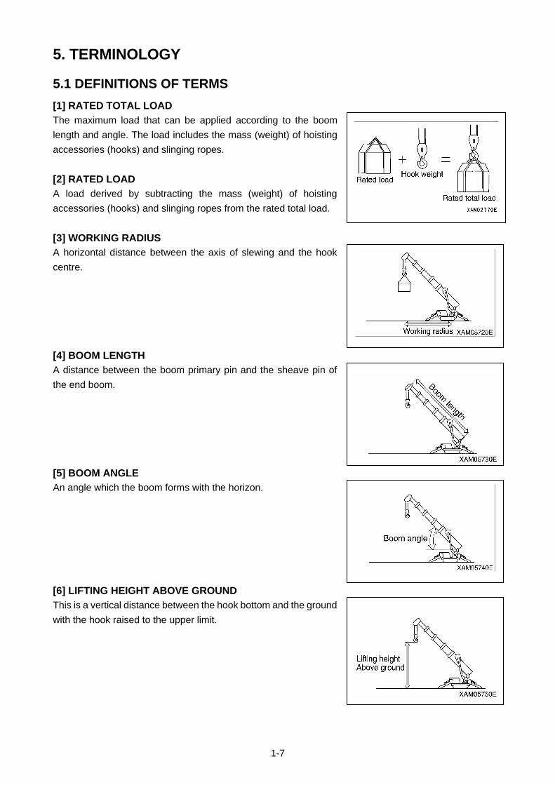
[1] RATED TOTAL LOAD
The maximum load that can be applied according to the boom
length and angle. The load includes the mass (weight) of hoisting
accessories (hooks) and slinging ropes.
[2] RATED LOAD
A load derived by subtracting the mass (weight) of hoisting
accessories (hooks) and slinging ropes from the rated total load.
[3] WORKING RADIUS
A horizontal distance between the axis of slewing and the hook
centre.
[4] BOOM LENGTH
A distance between the boom primary pin and the sheave pin of
the end boom.
[5] BOOM ANGLE
An angle which the boom forms with the horizon.
[6] LIFTING HEIGHT ABOVE GROUND
This is a vertical distance between the hook bottom and the ground
with the hook raised to the upper limit.
1-7
5.2 DIAGRAM OF WORKING RADIUS AND LIFTING HEIGHT
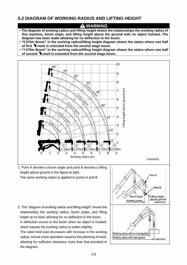
• The diagram of working radius and lifting height shows the relationships the working radius of
this machine, boom angle, and lifting height above the ground with no object hoisted. The diagram has been made allowing for no deflection in the boom.
• “5.575m Boom” in the working radius/lifting height diagram shows the status where one half of first
mark is extended from the second stage boom. • “7.075m Boom” in the working radius/lifting height diagram shows the status where one half
of second
mark is extended from the second stage boom.
1. Point A denotes a boom angle and point B denotes a lifting
height above ground in the figure at right.
The same working radius is applied to points A and B.
2. The “diagram of working radius and lifting height” shows the
relationships the working radius, boom angle, and lifting
height at no load, allowing for no deflection in the boom.
A deflection occurs in the boom when an object is hoisted,
which causes the working radius to widen slightly.
The rated total load decreases with increase in the working
radius. Actual crane operation requires the planning of work,
allowing for sufficient clearance more than that provided in
the diagram.
XAM09460E
1
0 1 2 3 4 5 6 7 8 9
1
2
3
4
5
6
7
8
9
1080˚
70˚
60˚
50˚
40˚
30˚
20˚
10˚
0˚
2.165m2
4.075m3
5.205m4
6.705m5
8.205m
2.535 m boom
4.075 m boom
5.575 m boom
7.075 m boom
8.575 m boom
Working radius (m)
Lifti
ng h
eigh
t abo
ve g
roun
d (m
)
1-8
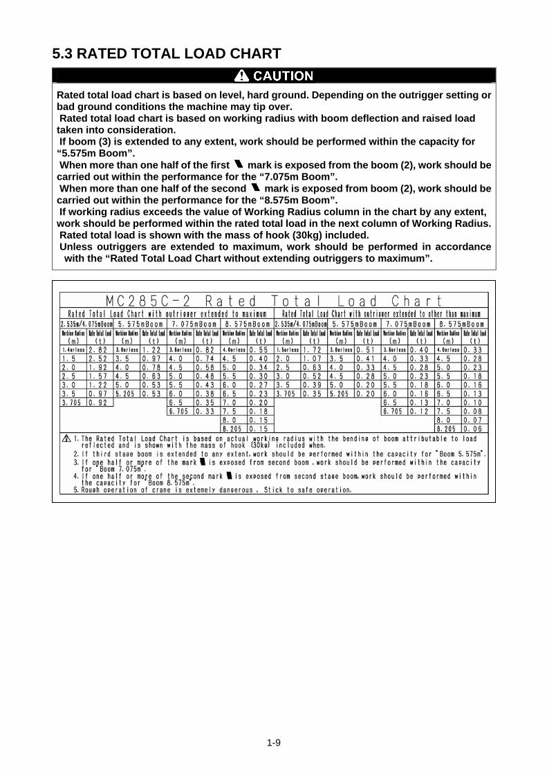
5.3 RATED TOTAL LOAD CHART
Rated total load chart is based on level, hard ground. Depending on the outrigger setting or bad ground conditions the machine may tip over. Rated total load chart is based on working radius with boom deflection and raised load taken into consideration. If boom (3) is extended to any extent, work should be performed within the capacity for “5.575m Boom”. When more than one half of the first
mark is exposed from the boom (2), work should be carried out within the performance for the “7.075m Boom”. When more than one half of the second
mark is exposed from boom (2), work should be carried out within the performance for the “8.575m Boom”. If working radius exceeds the value of Working Radius column in the chart by any extent, work should be performed within the rated total load in the next column of Working Radius. Rated total load is shown with the mass of hook (30kg) included. Unless outriggers are extended to maximum, work should be performed in accordance
with the “Rated Total Load Chart without extending outriggers to maximum”.
1-9

The rated total load chart provides the maximum loads that the crane is capable of hoisting objects in
parallel with the length of the boom. The loads are specified by working radius.
[1] BOOM LENGTH
“2.535m Boom”, “4.075m Boom”, “5.575m Boom”, “7.075m Boom” and “8.575m Boom” as shown on the
top horizontal column of the Rated Total Load Chart representing the following cases:
1. “2.535m Boom”: All the booms retracted.
XAM11140E
Boom 1 Boom 2 Boom 3
Boom 4
Boom 5
2. “4.075m Boom”: With boom (2) extended fully, remainder of booms are all retracted.
If boom (2) is extended to any extent, work should be carried out on the basis of performance for this
configuration.
XAM11150E
Boom 1 Boom 2 Boom 3 Boom 4
Boom 5
3. “5.575m Boom”: Boom extended to such extent that the first
mark of the boom (3) is exposed.
When the boom (3) is extended by any amount, however, work should be carried out according to the
performance shown in this column.
XAM11160E
Boom
First mark
1 Boom 2 Boom 3 Boom 4 Boom 5
1-10
4. “7.075m Boom”: Boom extended to such extent that the second
mark of the boom (3) is exposed.
When more than one-half of the first
mark of the boom (3) is exposed, your work should be carried
out in accordance with the performance of this column.
XAM11170E
Boom
Second mark First mark
1 Boom 2 Boom 3 Boom 4 Boom 5
5. “8.575m Boom”: All the booms extended fully.
When more than one-half of the second
mark of the boom (3) is exposed, your work should be carried
out in accordance with the performance of this column.
XAM11180E
Boom
Second mark First mark
1 Boom 2 Boom 3 Boom 4 Boom 5
1-11
[2] OUTRIGGER MAXIMUM EXTENSION
For crane work, be sure to extend all the outriggers. Never perform any crane work without setting up the outriggers. Otherwise the machine may tip over causing serious injury. Outriggers should be extended while watching levelling instrument so that the machine is set horizontally. Tilting the machine more than three degrees activates alarm buzzer. To stop buzzer, place the machine horizontally. For working without extending outriggers to maximum, see the values in “Rated Total Load Chart without extending outriggers to maximum” Working under improper value may cause the machine to tip over. If you have retracted any positioning pin of outrigger inner box or outrigger base by even one hole, your work should be performed in accordance with the value of “Rated Total Load with Outrigger Extended to other than Maximum” Swinging 360 degrees with a load lifted may expose the machine to an unstable position. Reduce the working radius and use sufficient care.
XAM09480E
4530
mm
3810
mm
4580mm
Swing center
45˚ 60˚
60˚45˚
The figure shown at right represents the condition “When the crane
is used with the outriggers extended to maximum” in the rated total
load chart.
NOTES
With the Outriggers extended to maximum" means that, with the outriggers set to the standard extension (60 degrees front and 45 degrees rear), inner boxes of all the outriggers pulled out fully and linkage bracket positioning pins set at the maximum position, the outriggers are placed on level ground.
XAM09490E
Positioning pin
Inner boxes
Any status other than that in the sketch to the right represents
“Outrigger Extended to other than Maximum”. See “OPERATION,
2.12 Setting up the outrigger” for proper placement.
NOTES
Even with all the outriggers extended to maximum, so long as the grounding surface of any one of them is not flush with bottom surface of track due to uneven terrain etc, the status will have to be defined as “Outriggers Extended to other than Maximum”.
1-12
5.4 ANGLE INDICATOR
• Use the Boom angle indicator to check the angle of the boom in operation when the crane is
operated from a distance; using a remote-controller, for instance. • Before hoisting a load, always see the Rated total load Chart to determine the correct boom length (i.e. number of boom sections used) and angle, then check the actual weight of the loadwith the applicable rated total load and ensure that weight of both of the load itself and sling etc, never exceeds the rated total load. The Boom angle indicator is helpful to confirm the boom angle.
The Boom angle indicators are attached to
both left and right sides of the No.1 Boom.
The indicator consists of a scale plate and a
pointer as shown in the figure on the right.
Use boom angle indicators as follows:
• Read the figure which the pointer indicates.
The figure shows the "Boom angle" of the
moment.
1-13


2-1
SAFETY
1. BASIC PRECAUTIONS 2- 2
2. DRIVING RELATED PRECAUTIONS 2- 7
3. TRANSPORT PRECAUTIONS 2-21
4. BATTERY HANDLING PRECAUTIONS 2-23
5. MAINTENANCE PRECAUTIONS 2-25
6. SAFETY LABEL LOCATIONS 2-32
All the safety precautions defined in this manual should always be read and observed. Failure to follow the safety precautions can cause serious personal injury or death.
2-2
1. BASIC PRECAUTIONS OBSERVE THE MANUAL AND SAFETY LABELS
• Read well and understand this manual as well as the safety labels labelled on various part of this Machine. Attempt to drive/operate without understanding fully may result in wrong operation that may cause personal or equipment accidents.
• Fully understand the proper use and inspection/maintenance procedures, and exercise safe works.
• Make sure this manual and the safety labels labelled on various part of this Machine are legible all the time. Whenever illegibility or loss occurs, order us or our sales service agency and put the safety label back to the original location.
DRIVING LICENSE
• Licenses are necessary to drive this Machine. Always obtain licenses before driving.
See “Introduction 4. Qualification for Operation” for details • The drivers are requested to receive educations and training of the handling methods and other subjects in the applicable office, and obtain sufficient driving operation skills before work.
WEAR PROTECTIVE EQUIPMENT AND CLOTHES SUITABLE FOR WORK • Always put on a helmet, safety shoes and safety belt. Make sure to wear, goggles, mask, gloves, hearing protectors, and safety belt suitable for the relevant working condition.
• Wear the necessary protective equipment suitable for the relevant working condition.
• Do not wear loose garments or accessory items that may catch an operation lever, starter switch, emergency stop switch or any protrusions that could cause unexpected movement of the Machine
COMMIT TO SAFE OPERATION
•Obey the instructions and signs given by the manager and work supervisor, and observe safety first during the work.
• Obey the crane work basics during work. • Always make sure to carry out inspections before using this machine. • Do not work under bad weather for instance strong wind, thunder or mist. • Do not drive under any condition when you are overtired, under the influence of alcohol or after taking a somnific drug.
• Obey all of the workplace rules, safety regulations and operation method sequences during driving operations and inspection/maintenance.
• Pay attention to surrounding conditions and pedestrians all the time when driving or working. Whenever pedestrian approaches unwarily, abort working once, and take a measure such as issuing a warning.
• When driving, be mentally prepared for unexpected situation and so that you can take measures immediately.
• Do not attempt any use out of the capabilities and purposes described in this manual under any circumstance.
• Observe the designated rated total load and work range when driving. • Do not attempt inattentive driving, harsh driving or awkward operation under any circumstance. • Pull out the key when leaving operation seat.
2-3
USE OF MACHINE THAT WAS RENTED OR PREVIOUSLY USED BY SOMEONE ELSE
Check the following subjects in writing before using any Machine that was rented or previously used by someone else. In addition, check the inspection record table for the maintenance conditions such as the periodic inspections. (1) Crane capacity (2) Crane maintenance condition (3) Behaviour and disadvantage unique to the crane (4) Other subjects that require attention when driving
(a) operating condition of the brakes, crutches and others (b) Presence/absence and lighting condition check-up of lightings and rotating lamps (c) Operation condition of hook, winches, boom, outriggers and related
PROVIDE SAFETY DEVICES FOR SURE
• Check that all guards and covers are attached properly. Repair immediately if damaged. • Understand how to use the safety devices well and use properly. • Do not detach any safety device under any circumstance. Keep control to achieve proper function all the time.
• Improper use of safety device may lead to serious accidents. • Do not rely too much on the safety devices whilst operating.
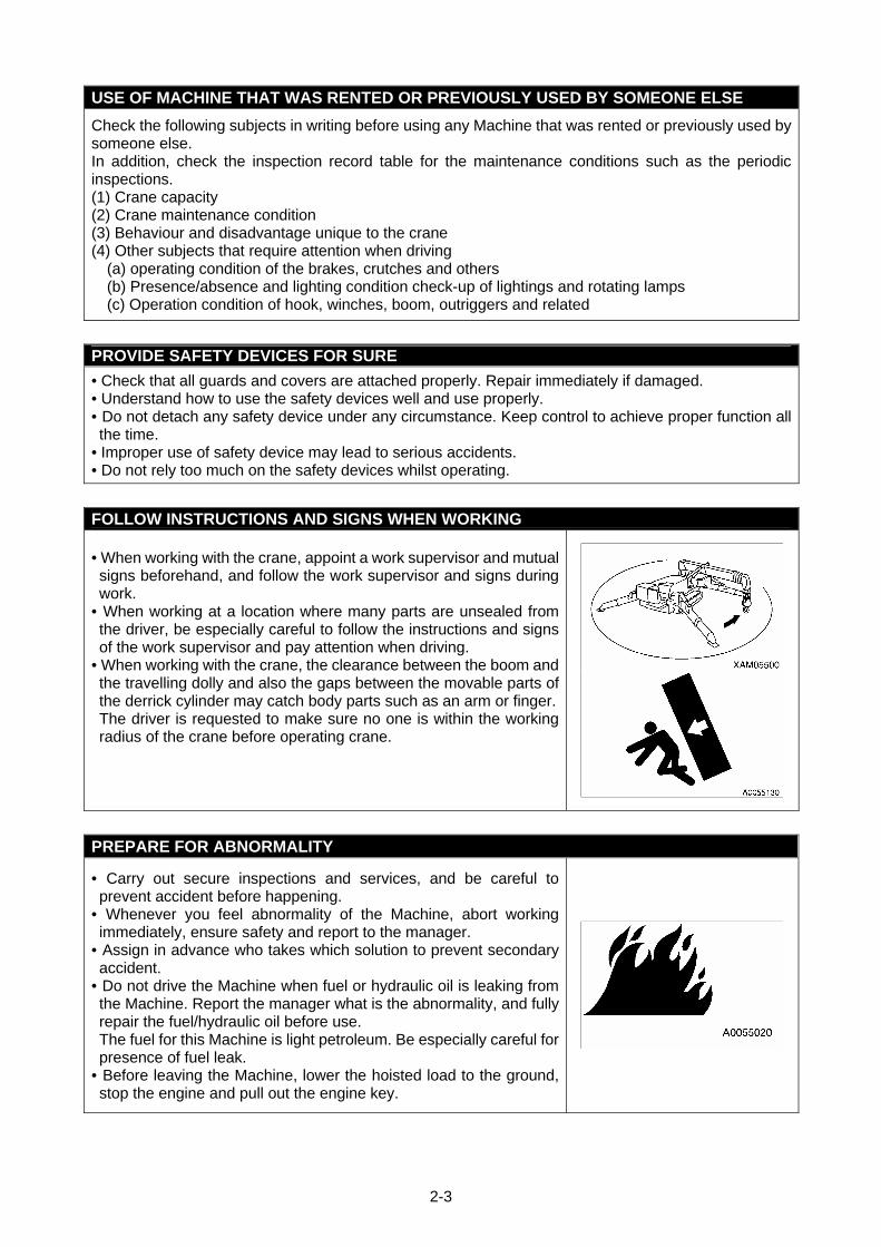
FOLLOW INSTRUCTIONS AND SIGNS WHEN WORKING • When working with the crane, appoint a work supervisor and mutual signs beforehand, and follow the work supervisor and signs during work.
• When working at a location where many parts are unsealed from the driver, be especially careful to follow the instructions and signs of the work supervisor and pay attention when driving.
• When working with the crane, the clearance between the boom and the travelling dolly and also the gaps between the movable parts of the derrick cylinder may catch body parts such as an arm or finger.The driver is requested to make sure no one is within the working radius of the crane before operating crane.
PREPARE FOR ABNORMALITY
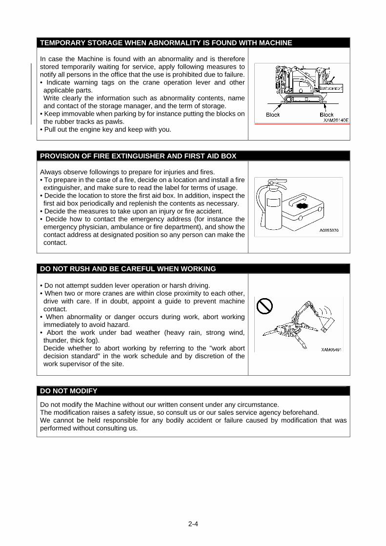
• Carry out secure inspections and services, and be careful to prevent accident before happening.
• Whenever you feel abnormality of the Machine, abort working immediately, ensure safety and report to the manager.
• Assign in advance who takes which solution to prevent secondary accident.
• Do not drive the Machine when fuel or hydraulic oil is leaking from the Machine. Report the manager what is the abnormality, and fully repair the fuel/hydraulic oil before use. The fuel for this Machine is light petroleum. Be especially careful for presence of fuel leak.
• Before leaving the Machine, lower the hoisted load to the ground, stop the engine and pull out the engine key.
2-4
TEMPORARY STORAGE WHEN ABNORMALITY IS FOUND WITH MACHINE
In case the Machine is found with an abnormality and is therefore stored temporarily waiting for service, apply following measures to notify all persons in the office that the use is prohibited due to failure.• Indicate warning tags on the crane operation lever and other applicable parts. Write clearly the information such as abnormality contents, name and contact of the storage manager, and the term of storage.
• Keep immovable when parking by for instance putting the blocks on the rubber tracks as pawls.
• Pull out the engine key and keep with you.
PROVISION OF FIRE EXTINGUISHER AND FIRST AID BOX
Always observe followings to prepare for injuries and fires. • To prepare in the case of a fire, decide on a location and install a fire extinguisher, and make sure to read the label for terms of usage.
• Decide the location to store the first aid box. In addition, inspect the first aid box periodically and replenish the contents as necessary.
• Decide the measures to take upon an injury or fire accident. • Decide how to contact the emergency address (for instance the emergency physician, ambulance or fire department), and show the contact address at designated position so any person can make the contact.
DO NOT RUSH AND BE CAREFUL WHEN WORKING
• Do not attempt sudden lever operation or harsh driving. • When two or more cranes are within close proximity to each other, drive with care. If in doubt, appoint a guide to prevent machine contact.
• When abnormality or danger occurs during work, abort working immediately to avoid hazard.
• Abort the work under bad weather (heavy rain, strong wind, thunder, thick fog). Decide whether to abort working by referring to the "work abort decision standard" in the work schedule and by discretion of the work supervisor of the site.
DO NOT MODIFY
Do not modify the Machine without our written consent under any circumstance. The modification raises a safety issue, so consult us or our sales service agency beforehand. We cannot be held responsible for any bodily accident or failure caused by modification that was performed without consulting us.
2-5
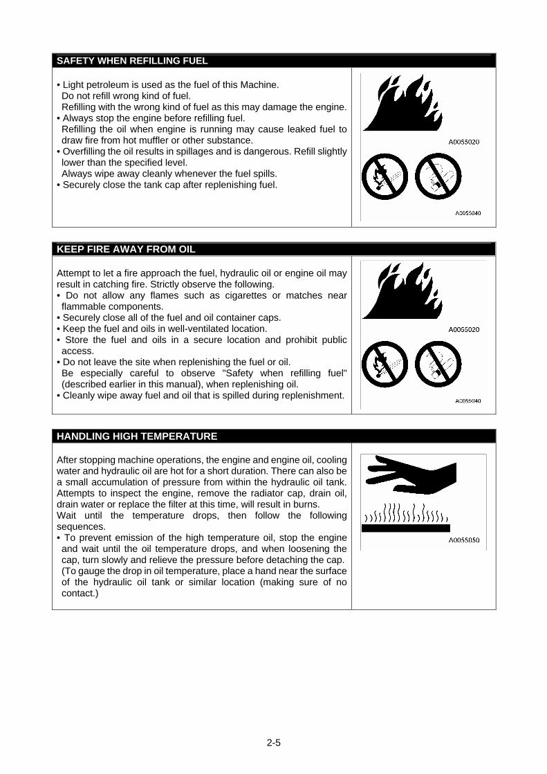
SAFETY WHEN REFILLING FUEL • Light petroleum is used as the fuel of this Machine. Do not refill wrong kind of fuel. Refilling with the wrong kind of fuel as this may damage the engine.
• Always stop the engine before refilling fuel. Refilling the oil when engine is running may cause leaked fuel to draw fire from hot muffler or other substance.
• Overfilling the oil results in spillages and is dangerous. Refill slightly lower than the specified level. Always wipe away cleanly whenever the fuel spills.
• Securely close the tank cap after replenishing fuel.
KEEP FIRE AWAY FROM OIL Attempt to let a fire approach the fuel, hydraulic oil or engine oil may result in catching fire. Strictly observe the following. • Do not allow any flames such as cigarettes or matches near flammable components.
• Securely close all of the fuel and oil container caps. • Keep the fuel and oils in well-ventilated location. • Store the fuel and oils in a secure location and prohibit public access.
• Do not leave the site when replenishing the fuel or oil. Be especially careful to observe "Safety when refilling fuel" (described earlier in this manual), when replenishing oil.
• Cleanly wipe away fuel and oil that is spilled during replenishment.
HANDLING HIGH TEMPERATURE
After stopping machine operations, the engine and engine oil, cooling water and hydraulic oil are hot for a short duration. There can also be a small accumulation of pressure from within the hydraulic oil tank. Attempts to inspect the engine, remove the radiator cap, drain oil, drain water or replace the filter at this time, will result in burns. Wait until the temperature drops, then follow the following sequences. • To prevent emission of the high temperature oil, stop the engine and wait until the oil temperature drops, and when loosening the cap, turn slowly and relieve the pressure before detaching the cap.(To gauge the drop in oil temperature, place a hand near the surface of the hydraulic oil tank or similar location (making sure of no contact.)
2-6
BEWARE OF ASBESTOS DUST
Inhalation of asbestos may result in lung cancer. This Machine does not contain asbestos, but asbestos may be found in the wall, ceiling or other construction locations within the worksite of this Machine. In addition, be careful of the followings when working with a material that may contain asbestos. • Put on designated dust free mask and/or other protection equipment where necessary.
• Do not use compressed air for cleaning. • Spray water when cleaning to prevent airborne asbestos dust. • Always work at windward location when driving the Machine at a site that may contain asbestos dusts.
• Strictly observe the assigned rules related to the working site and environmental standard.
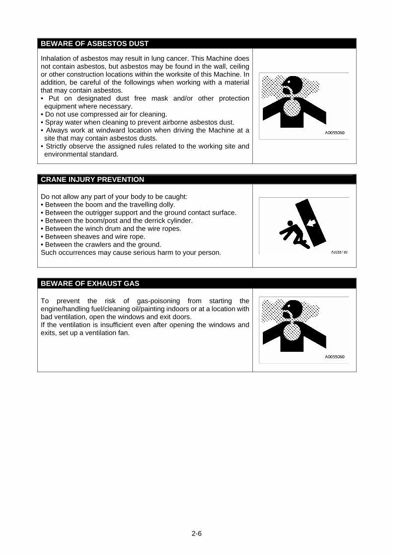
CRANE INJURY PREVENTION Do not allow any part of your body to be caught: • Between the boom and the travelling dolly. • Between the outrigger support and the ground contact surface. • Between the boom/post and the derrick cylinder. • Between the winch drum and the wire ropes. • Between sheaves and wire rope. • Between the crawlers and the ground. Such occurrences may cause serious harm to your person.
BEWARE OF EXHAUST GAS To prevent the risk of gas-poisoning from starting the engine/handling fuel/cleaning oil/painting indoors or at a location with bad ventilation, open the windows and exit doors. If the ventilation is insufficient even after opening the windows and exits, set up a ventilation fan.
2-7
2. DRIVING RELATED PRECAUTIONS
2.1 BEFORE STARTING ENGINE
ESTABLISH SAFETY OF WORKING SITE
• Confirm that no danger is present at the working site before starting work.
• Investigate the ground and road surface condition of the working site and decide the best working method.
• Flatten the inclination of the working site as much as possible before starting work. Also, if sands and gravels are excessive, spray water before work.
• When working over the roadway, enforce keep out by for instance placing guides or surrounding by barriers, and ensure the safety of the traffic vehicles and pedestrians.
• Enforce keep out to prevent people from entering the working site and apply measures to prevent people from approaching. Attempt to approach moving Machine may result in hard collision by contact or pinching, and may result in serious bodily accidents and deaths.
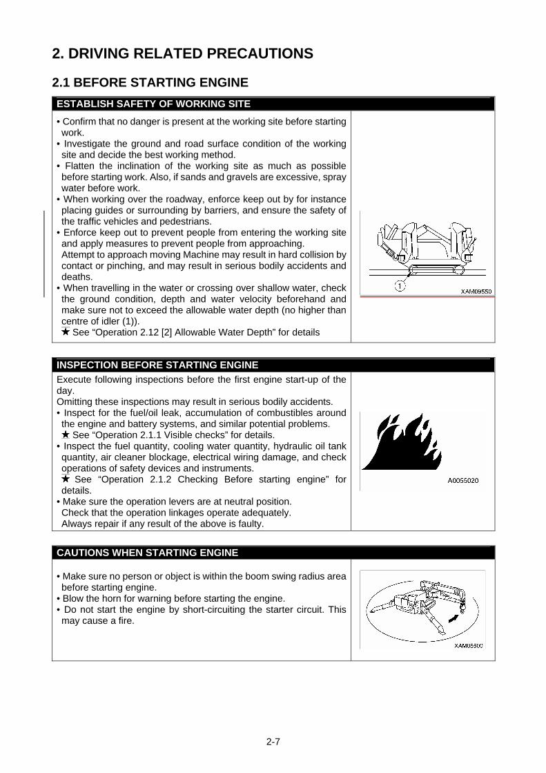
• When travelling in the water or crossing over shallow water, check the ground condition, depth and water velocity beforehand and make sure not to exceed the allowable water depth (no higher than centre of idler (1)).
See “Operation 2.12 [2] Allowable Water Depth” for details
INSPECTION BEFORE STARTING ENGINE
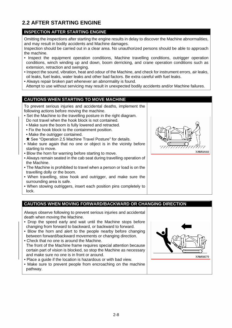
Execute following inspections before the first engine start-up of the day. Omitting these inspections may result in serious bodily accidents. • Inspect for the fuel/oil leak, accumulation of combustibles around the engine and battery systems, and similar potential problems.
See “Operation 2.1.1 Visible checks” for details. • Inspect the fuel quantity, cooling water quantity, hydraulic oil tank quantity, air cleaner blockage, electrical wiring damage, and check operations of safety devices and instruments.
See “Operation 2.1.2 Checking Before starting engine” for details.
• Make sure the operation levers are at neutral position. Check that the operation linkages operate adequately. Always repair if any result of the above is faulty.
CAUTIONS WHEN STARTING ENGINE • Make sure no person or object is within the boom swing radius area before starting engine.
• Blow the horn for warning before starting the engine. • Do not start the engine by short-circuiting the starter circuit. This may cause a fire.
2-8
2.2 AFTER STARTING ENGINE
INSPECTION AFTER STARTING ENGINE
Omitting the inspections after starting the engine results in delay to discover the Machine abnormalities, and may result in bodily accidents and Machine damages. Inspection should be carried out in a clear area. No unauthorized persons should be able to approach the machine. • Inspect the equipment operation conditions, Machine travelling conditions, outrigger operation conditions, winch winding up and down, boom derricking, and crane operation conditions such as extension, retraction and swinging.
• Inspect the sound, vibration, heat and odour of the Machine, and check for instrument errors, air leaks, oil leaks, fuel leaks, water leaks and other bad factors. Be extra careful with fuel leaks.
• Always repair broken part whenever an abnormality is found. Attempt to use without servicing may result in unexpected bodily accidents and/or Machine failures.
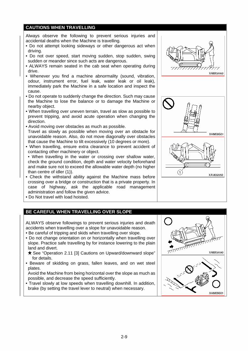
CAUTIONS WHEN STARTING TO MOVE MACHINE
To prevent serious injuries and accidental deaths, implement the following actions before moving the machine. • Set the Machine to the travelling posture in the right diagram. Do not travel when the hook block is not contained. • Make sure the boom is fully lowered and retracted. • Fix the hook block to the containment position. • Make the outrigger contained.
See “Operation 2.5 Machine Travel Posture” for details. • Make sure again that no one or object is in the vicinity before starting to move.
• Blow the horn for warning before starting to move. • Always remain seated in the cab seat during travelling operation of the Machine.
• The Machine is prohibited to travel when a person or load is on the travelling dolly or the boom.
• When travelling, stow hook and outrigger, and make sure the surrounding area is safe.
• When stowing outriggers, insert each position pins completely to lock.
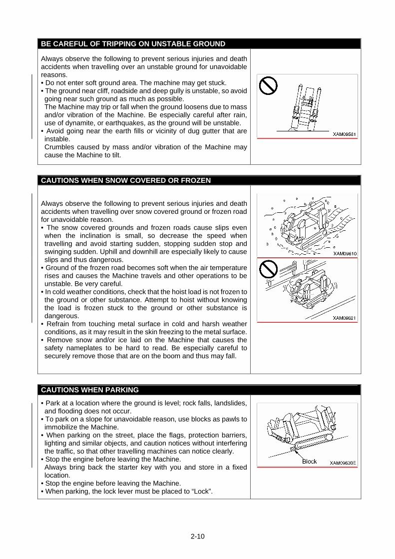
CAUTIONS WHEN MOVING FORWARD/BACKWARD OR CHANGING DIRECTION
Always observe following to prevent serious injuries and accidental death when moving the Machine. • Drop the speed early and wait until the Machine stops before changing from forward to backward, or backward to forward.
• Blow the horn and alert to the people nearby before changing between forward/backward movements or changing direction.
• Check that no one is around the Machine. The front of the Machine frame requires special attention because certain part of vision is blocked, so stop the Machine as necessary and make sure no one is in front or around.
• Place a guide if the location is hazardous or with bad view. • Make sure to prevent people from encroaching on the machine pathway.
2-9
CAUTIONS WHEN TRAVELLING
Always observe the following to prevent serious injuries and accidental deaths when the Machine is travelling. • Do not attempt looking sideways or other dangerous act when driving.
• Do not over speed, start moving sudden, stop sudden, swing sudden or meander since such acts are dangerous.
• ALWAYS remain seated in the cab seat when operating during drive.
• Whenever you find a machine abnormality (sound, vibration, odour, instrument error, fuel leak, water leak or oil leak), immediately park the Machine in a safe location and inspect the cause.
• Do not operate to suddenly change the direction. Such may cause the Machine to lose the balance or to damage the Machine or nearby object.
• When travelling over uneven terrain, travel as slow as possible to prevent tripping, and avoid acute operation when changing the direction.
• Avoid moving over obstacles as much as possible. Travel as slowly as possible when moving over an obstacle for unavoidable reason. Also, do not move diagonally over obstacles that cause the Machine to tilt excessively (10 degrees or more).
• When travelling, ensure extra clearance to prevent accident of contacting other machinery or object. • When travelling in the water or crossing over shallow water, check the ground condition, depth and water velocity beforehand and make sure not to exceed the allowable water depth (no higher than centre of idler (1)).
• Check the withstand ability against the Machine mass before crossing over a bridge or construction that is a private property. In case of highway, ask the applicable road management administration and follow the given advice.
• Do Not travel with load hoisted.
BE CAREFUL WHEN TRAVELLING OVER SLOPE
ALWAYS observe followings to prevent serious injuries and death accidents when travelling over a slope for unavoidable reason. • Be careful of tripping and skids when travelling over slope. • Do not change orientation on or horizontally when travelling over slope. Practice safe travelling by for instance lowering to the plain land and divert.
See “Operation 2.11 [3] Cautions on Upward/downward slope” for details.
• Beware of skidding on grass, fallen leaves, and on wet steel plates. Avoid the Machine from being horizontal over the slope as much as possible, and decrease the speed sufficiently.
• Travel slowly at low speeds when travelling downhill. In addition, brake (by setting the travel lever to neutral) when necessary.
2-10
BE CAREFUL OF TRIPPING ON UNSTABLE GROUND
Always observe the following to prevent serious injuries and death accidents when travelling over an unstable ground for unavoidable reasons. • Do not enter soft ground area. The machine may get stuck. • The ground near cliff, roadside and deep gully is unstable, so avoid going near such ground as much as possible. The Machine may trip or fall when the ground loosens due to mass and/or vibration of the Machine. Be especially careful after rain, use of dynamite, or earthquakes, as the ground will be unstable.
• Avoid going near the earth fills or vicinity of dug gutter that are instable. Crumbles caused by mass and/or vibration of the Machine may cause the Machine to tilt.
CAUTIONS WHEN SNOW COVERED OR FROZEN
Always observe the following to prevent serious injuries and death accidents when travelling over snow covered ground or frozen road for unavoidable reason. • The snow covered grounds and frozen roads cause slips even when the inclination is small, so decrease the speed when travelling and avoid starting sudden, stopping sudden stop and swinging sudden. Uphill and downhill are especially likely to cause slips and thus dangerous.
• Ground of the frozen road becomes soft when the air temperature rises and causes the Machine travels and other operations to be unstable. Be very careful.
• In cold weather conditions, check that the hoist load is not frozen to the ground or other substance. Attempt to hoist without knowing the load is frozen stuck to the ground or other substance is dangerous.
• Refrain from touching metal surface in cold and harsh weather conditions, as it may result in the skin freezing to the metal surface.
• Remove snow and/or ice laid on the Machine that causes the safety nameplates to be hard to read. Be especially careful to securely remove those that are on the boom and thus may fall.
CAUTIONS WHEN PARKING
• Park at a location where the ground is level; rock falls, landslides, and flooding does not occur.
• To park on a slope for unavoidable reason, use blocks as pawls to immobilize the Machine.
• When parking on the street, place the flags, protection barriers, lighting and similar objects, and caution notices without interfering the traffic, so that other travelling machines can notice clearly.
• Stop the engine before leaving the Machine. Always bring back the starter key with you and store in a fixed location.
• Stop the engine before leaving the Machine. • When parking, the lock lever must be placed to “Lock”.
2-11
CAUTIONS UNDER COLD WEATHER
• Remove snow and defrost the swing gear, boom and winch related parts, and check the movements before starting work.
• Warm up enough. Operating levers and switches with a cold engine causes the machine to be lethargic, and may result in unexpected accidents.
• Avoid sharp acceleration for a short time after initial engine ignition.• Increase the oil temperature of the hydraulic circuit by relieving the oil pressure (let the pneumatic oil to escape to the hydraulic oil tank by raising to above the hydraulic circuit set pressure) by using operation lever. Doing so improves the Machine reactions and prevents improper operations.
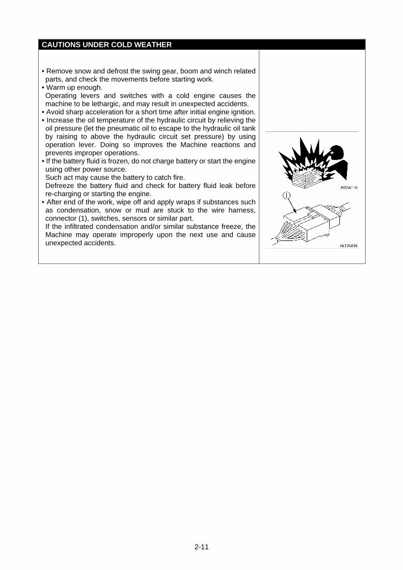
• If the battery fluid is frozen, do not charge battery or start the engine using other power source. Such act may cause the battery to catch fire. Defreeze the battery fluid and check for battery fluid leak before re-charging or starting the engine.
• After end of the work, wipe off and apply wraps if substances such as condensation, snow or mud are stuck to the wire harness, connector (1), switches, sensors or similar part. If the infiltrated condensation and/or similar substance freeze, the Machine may operate improperly upon the next use and cause unexpected accidents.
2-12
2.3 WORKING WITH CRANE
INSPECTION BEFORE STARTING WORK
Check that the safety devices and crane operate properly. • Operate each of the operation levers and switches under no load, and check that operations take place without abnormality. Repair immediately if any abnormality exists.
• Check that the safety devices such as the moment limiter, outrigger safety device, and over hoist detector / automatic stop device activate properly.
CAUTIONS WHEN HANDLING MOMENT LIMITER
• Use/store the moment limiter under the following ranges of ambient temperature. Temperature of use: 10 to 50 °C Storage temperature: -20 to 60 °C
• Avoid direct sunlight so that the temperature of the moment limiter body does not exceed the above range.
• Avoid locations with strong acid or alkaline atmosphere as much as possible. Otherwise, unexpected failures may occur.
• Do not apply impact to the moment limiter body for instance by colliding with an object. Such attempt may damage the case and may result in failures and improper operations.
• Do not push the panel sheet of the moment limiter body by a force more than necessary or push with sharp object such as a tip of a screwdriver. Such act may damage the panel sheet and may result in failures and improper operations.
• Do not remove the case cover or panel sheet from, or disassemble the moment limiter body. Such act may damage case and/or panel sheet and may result in failures and improper operations.
CAUTIONS WHEN SETTING UP MOMENT LIMITER • The moment limiter calculates the moments assuming the Machine is level. If you work with the crane when the Machine is not level, warnings and alarms are not issued even when the rated total load is near. Always set the outrigger horizontally to the ground while looking at the level gauge.
• Before using the crane, check that the boom angle display, boom length display and real load display of the moment limiter are displayed correctly following the crane movements. Attempt to use without correct display results in failure to obtain correct measurement result and may result in serious bodily accidents caused by reasons such as an improper operation and/or breakage of nearby equipment.
• Always make sure the wire strand setting of the moment limiter matches with the wire strand of the crane. If the wire strands do not match, always let the wire strands match by changing the wire strand setting of the moment limiter or by changing the wire strand of the crane. Attempt to use with unmatched wire strands results in failure to obtain correct measurement result and may result in serious bodily accidents caused by reasons such as an improper operation and/or breakage of nearby equipment.
• Do not carelessly change the setting when measuring with the moment limiter. Such attempt results in failure to obtain correct measurement result and may result in serious bodily accidents caused by reasons such as an improper operation and/or breakage of nearby equipment.
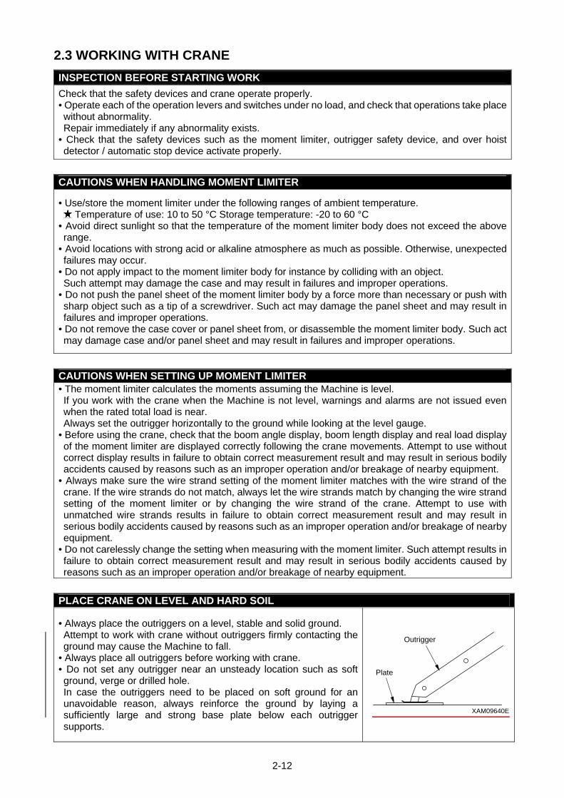
PLACE CRANE ON LEVEL AND HARD SOIL
• Always place the outriggers on a level, stable and solid ground. Attempt to work with crane without outriggers firmly contacting the ground may cause the Machine to fall.
• Always place all outriggers before working with crane. • Do not set any outrigger near an unsteady location such as soft ground, verge or drilled hole. In case the outriggers need to be placed on soft ground for an unavoidable reason, always reinforce the ground by laying a sufficiently large and strong base plate below each outrigger supports.
XAM09640E
Outrigger
Plate
2-13
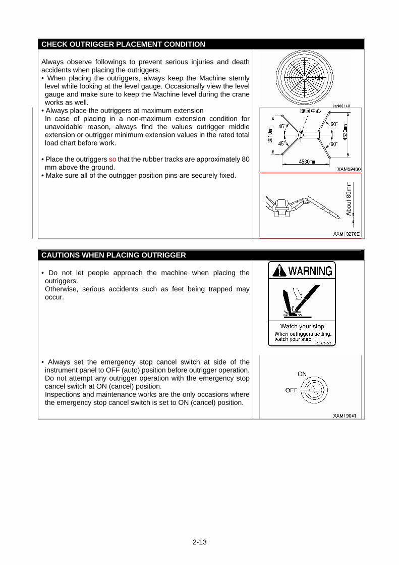
CHECK OUTRIGGER PLACEMENT CONDITION Always observe followings to prevent serious injuries and death accidents when placing the outriggers. • When placing the outriggers, always keep the Machine sternly level while looking at the level gauge. Occasionally view the level gauge and make sure to keep the Machine level during the crane works as well.
• Always place the outriggers at maximum extension In case of placing in a non-maximum extension condition for unavoidable reason, always find the values outrigger middle extension or outrigger minimum extension values in the rated total load chart before work.
• Place the outriggers so that the rubber tracks are approximately 80 mm above the ground.
• Make sure all of the outrigger position pins are securely fixed.
CAUTIONS WHEN PLACING OUTRIGGER • Do not let people approach the machine when placing the outriggers. Otherwise, serious accidents such as feet being trapped may occur.
• Always set the emergency stop cancel switch at side of the instrument panel to OFF (auto) position before outrigger operation.Do not attempt any outrigger operation with the emergency stop cancel switch at ON (cancel) position. Inspections and maintenance works are the only occasions where the emergency stop cancel switch is set to ON (cancel) position.
2-14
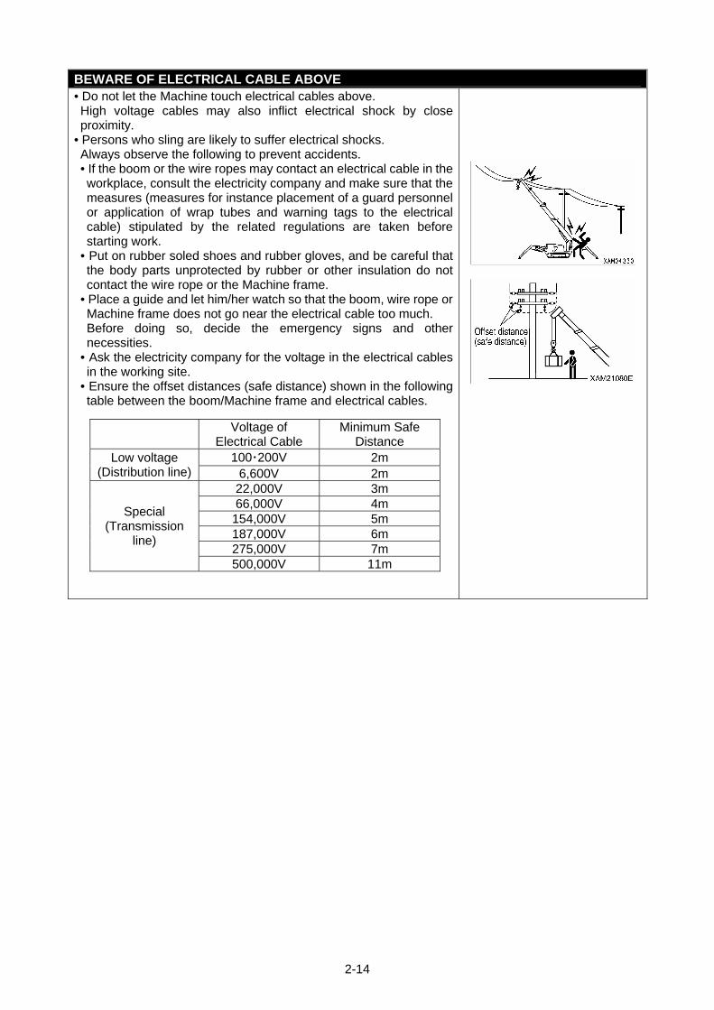
BEWARE OF ELECTRICAL CABLE ABOVE • Do not let the Machine touch electrical cables above. High voltage cables may also inflict electrical shock by close proximity.
• Persons who sling are likely to suffer electrical shocks. Always observe the following to prevent accidents. • If the boom or the wire ropes may contact an electrical cable in the workplace, consult the electricity company and make sure that the measures (measures for instance placement of a guard personnel or application of wrap tubes and warning tags to the electrical cable) stipulated by the related regulations are taken before starting work.
• Put on rubber soled shoes and rubber gloves, and be careful that the body parts unprotected by rubber or other insulation do not contact the wire rope or the Machine frame.
• Place a guide and let him/her watch so that the boom, wire rope or Machine frame does not go near the electrical cable too much. Before doing so, decide the emergency signs and other necessities.
• Ask the electricity company for the voltage in the electrical cables in the working site.
• Ensure the offset distances (safe distance) shown in the following table between the boom/Machine frame and electrical cables.
Voltage of
Electrical Cable Minimum Safe
Distance 100・200V 2m Low voltage
(Distribution line) 6,600V 2m 22,000V 3m 66,000V 4m
154,000V 5m 187,000V 6m 275,000V 7m
Special (Transmission
line)
500,000V 11m
2-15
MEASURES WHEN CHARGE ACCIDENT OCCURS
If an electric surge occurs, react calmly and apply these solutions in sequence. 1. Report
Immediately report to the electricity company or related management company, and receive instructions for the power transmission stop, emergency procedures and related.
2. Evacuation of related personnel from vicinity of Machine Remove all personnel, including workers, from the vicinity of the machine to prevent secondary disasters. Personnel who suffered electrical shock by holding a sling rope, guide rope or other conductor when the Machine was charged should evacuate by his/her own effort. Do not try to help personnel affected by electric shock. Otherwise, secondary electrical shock accident occurs.
3. Emergency procedure In the case of personnel receiving an electric shock due to the machine being electrically charged, do the following: (1) If the machine is operational, immediately move it to a safe location away from the cause of the
electrical charge. Take care not to break or disrupt the distribution power cable. (2) Move the machine to a safe location, after making sure the machine is not electrically charged,
and then carry any affected personnel to hospital. 4. Measure after accident
After accident, do not reuse as is. Such attempt may cause unexpected accidents and enhances failures. Ask us or our sales service agency for repair.
CAUTIONS WHEN WORKING WITH CRANE IN LOCATION WITH HIGH OUTPUT MICROWAVE EMISSION
Working with crane near high output microwave emission equipment such as a radar or TV/radio broadcast antenna causes the crane construction to be exposed to the microwave and generates induced current, therefore is very dangerous. In addition, the mechatronics may become haywire. Establish grounding between the Machine frame and the ground when working in such location. In addition, slingers are requested to wear rubber boots and rubber gloves since risk of electrical shock by contacting parts such as the hook or wire exists.
2-16
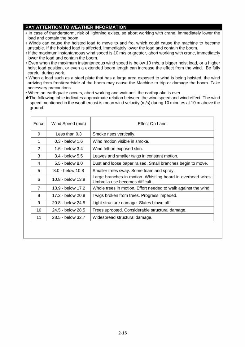
PAY ATTENTION TO WEATHER INFORMATION • In case of thunderstorm, risk of lightning exists, so abort working with crane, immediately lower the load and contain the boom.
• Winds can cause the hoisted load to move to and fro, which could cause the machine to become unstable. If the hoisted load is affected, immediately lower the load and contain the boom.
• If the maximum instantaneous wind speed is 10 m/s or greater, abort working with crane, immediately lower the load and contain the boom.
• Even when the maximum instantaneous wind speed is below 10 m/s, a bigger hoist load, or a higher hoist load position, or even a extended boom length can increase the effect from the wind. Be fully careful during work.
• When a load such as a steel plate that has a large area exposed to wind is being hoisted, the wind arriving from front/rear/side of the boom may cause the Machine to trip or damage the boom. Take necessary precautions.
• When an earthquake occurs, abort working and wait until the earthquake is over. The following table indicates approximate relation between the wind speed and wind effect. The wind speed mentioned in the weathercast is mean wind velocity (m/s) during 10 minutes at 10 m above the ground.
Force Wind Speed (m/s) Effect On Land
0 Less than 0.3 Smoke rises vertically.
1 0.3 - below 1.6 Wind motion visible in smoke.
2 1.6 - below 3.4 Wind felt on exposed skin.
3 3.4 - below 5.5 Leaves and smaller twigs in constant motion.
4 5.5 - below 8.0 Dust and loose paper raised. Small branches begin to move.
5 8.0 - below 10.8 Smaller trees sway. Some foam and spray.
6 10.8 - below 13.9 Large branches in motion. Whistling heard in overhead wires. Umbrella use becomes difficult.
7 13.9 - below 17.2 Whole trees in motion. Effort needed to walk against the wind.
8 17.2 - below 20.8 Twigs broken from trees. Progress impeded.
9 20.8 - below 24.5 Light structure damage. Slates blown off.
10 24.5 - below 28.5 Trees uprooted. Considerable structural damage.
11 28.5 - below 32.7 Widespread structural damage.
2-17
CAUTIONS WHEN SLINGING
• Check the following before hoisting a load. Attempt to hoist the load without checking may result in serious bodily accidents by a drop of the load or tripping. • Observe the values in the rated total load chart. • Hoist from the centre of gravity of the load. • Check that the wire ropes of the hook block are perpendicular to the ground. • When the load leaves the ground, stop winding up the load once and check whether the load is stable.
• Before hoisting a slung load, always check whether the sling wire rope "retainer device" of the hook block is hung correctly. If the "retainer device" is not hung, the wire rope may leave the hook block and cause the load to fall resulting in a serious accident.
• Larger wire rope angle when hoisting the load increases force that applies to the wire rope even when the load weight is unchanged, thus may cause the wire rope to snip. Pay enough consideration well when slinging to prevent excessive for from applying to the wire rope.
• Only hoist one load at a time. Attempts to hoist more than one load may cause the hoist bracket to hit and damage the other hoisted load, the loads to move and loose balance and cause trip, or other cause of serious accidents. Do not hoist more than one load even if the total combined weight is within the rated total load.
• Hoisting of lengthy load causes the load to lose balance and is dangerous. In case such load, hoist vertically by using a cramp, or achieve balance of the hoisted load by applying a rope to both ends of the load.
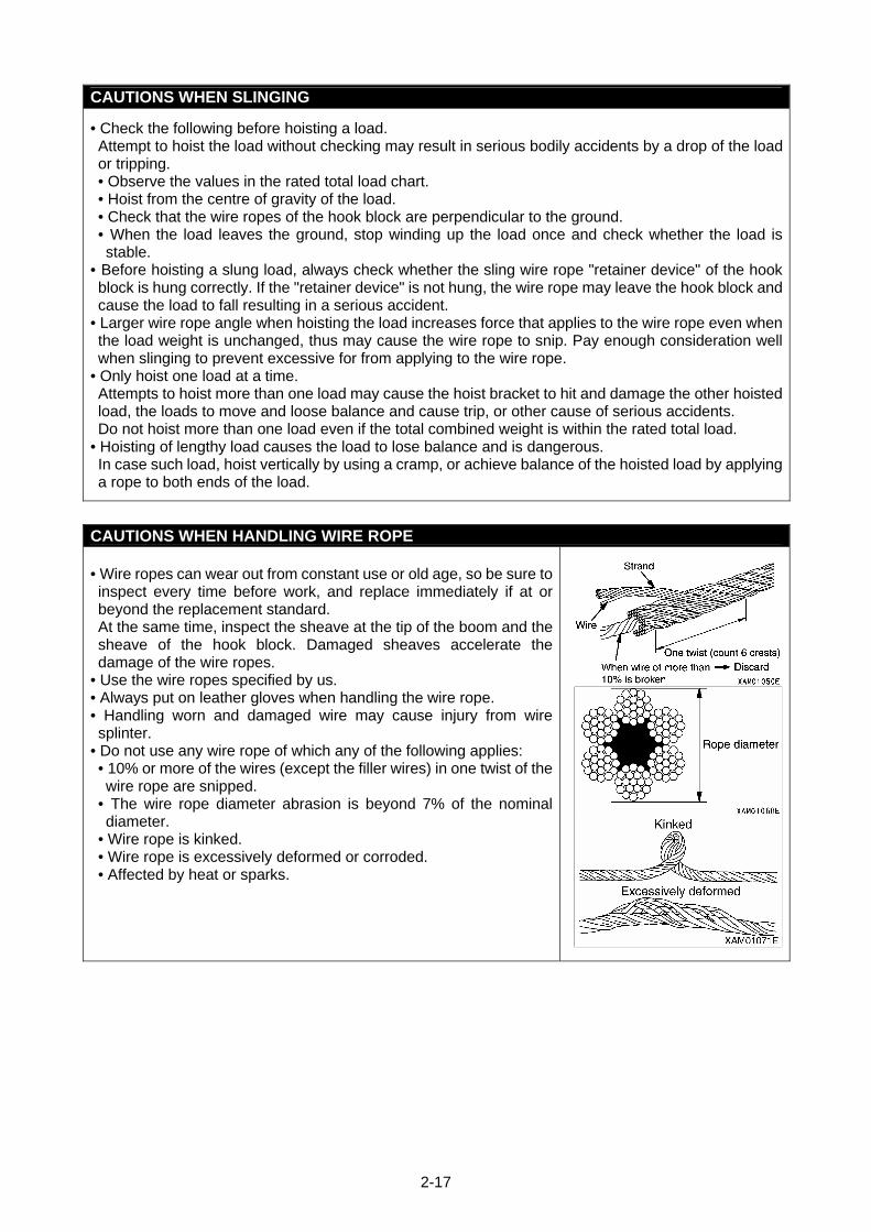
CAUTIONS WHEN HANDLING WIRE ROPE • Wire ropes can wear out from constant use or old age, so be sure to inspect every time before work, and replace immediately if at or beyond the replacement standard. At the same time, inspect the sheave at the tip of the boom and the sheave of the hook block. Damaged sheaves accelerate the damage of the wire ropes.
• Use the wire ropes specified by us. • Always put on leather gloves when handling the wire rope. • Handling worn and damaged wire may cause injury from wire splinter.
• Do not use any wire rope of which any of the following applies: • 10% or more of the wires (except the filler wires) in one twist of the wire rope are snipped.
• The wire rope diameter abrasion is beyond 7% of the nominal diameter.
• Wire rope is kinked. • Wire rope is excessively deformed or corroded. • Affected by heat or sparks.
2-18
CAUTIONS WHEN WORKING WITH CRANE
• Be sure to verify that the emergency stop cancel switch is at the OFF (auto) position before operating the crane. Do not attempt the crane operation when the emergency stop cancel switch is at the ON (cancel) position. The emergency stop cancel switch is permitted to be at the ON (cancel) position only during inspection or maintenance works.
• Crane works are not possible when the outriggers are placed in extension condition. Also, the crane work is halted when an outrigger support leaves the ground during the crane work. Securely place the crane in the extension condition, and avoid operations and works that may cause the machine to vibrate when working with the crane.
• Attempt to work beyond the capacity of the Machine may cause serious accidents and failures caused by for instance tripping or fluctuation. Observe the rated total load chart when working with the crane.
• Do not travel with a load being hoisted under any circumstances. This may cause the crane to fall over resulting in serious accidents.
• Be slow when operating the crane. Sudden lever or accelerator use may cause risks such as shaking, dropping of the load or collision with the surrounding. Be especially careful to be slow during the swing operations.
• Do not allow unauthorized personnel to approach the working area because of falling load risks which may cause serious accidents. Also consider that the working radius increases when the load is hoisted and the boom is deflected. • Bad weather can impair vision. Work lamps or other lighting devices should be used for crane safety in dark places. When the view is bad because of bad weather (rain, fog, snow), stop working and wait until the weather recovers.
• Do not use for purpose, for instance raising a person using a crane, other than the true purpose. • If the overwinding detector alarm buzzer is heard, immediately remove your hand from the winch lever. The hook block winding stops. Then, operate the winch lever to Down (push forward) to wind down the hook block. In addition, the hook block is wound up when the boom is extended, so be sure to ensure extra clearance between the boom and the hook block during work.
• When the boom extends, the hook block is wound up. Operate the winch lever to Down (push forward) to wind down the hook block while you extend the boom.
• Whenever an overload occurs during work, lower the load by winding down the winch by setting the winch lever to Down (push forward). Do not raise or lower the boom acutely. Such attempt may cause serious accidents by tripping.
• The volume of the hydraulic oil in each of the cylinders changes depending on the temperature. By leaving idle with a load being hoisted, as the time passes by the oil temperature drops and the hydraulic oil volume decreases, and changes such as the boom derrick angle decrease and boom length decrease may occur. In that case, execute boom derricking operations and boom extension operations appropriately to correct.
• Do not leave the driving operation position when a load is hoisted. Lower the load before leaving the Machine.
• Keep the hook block wound up when not in use. This is to prevent persons colliding with the unloaded hook block.
• Operator must not leave operation seat during operation.
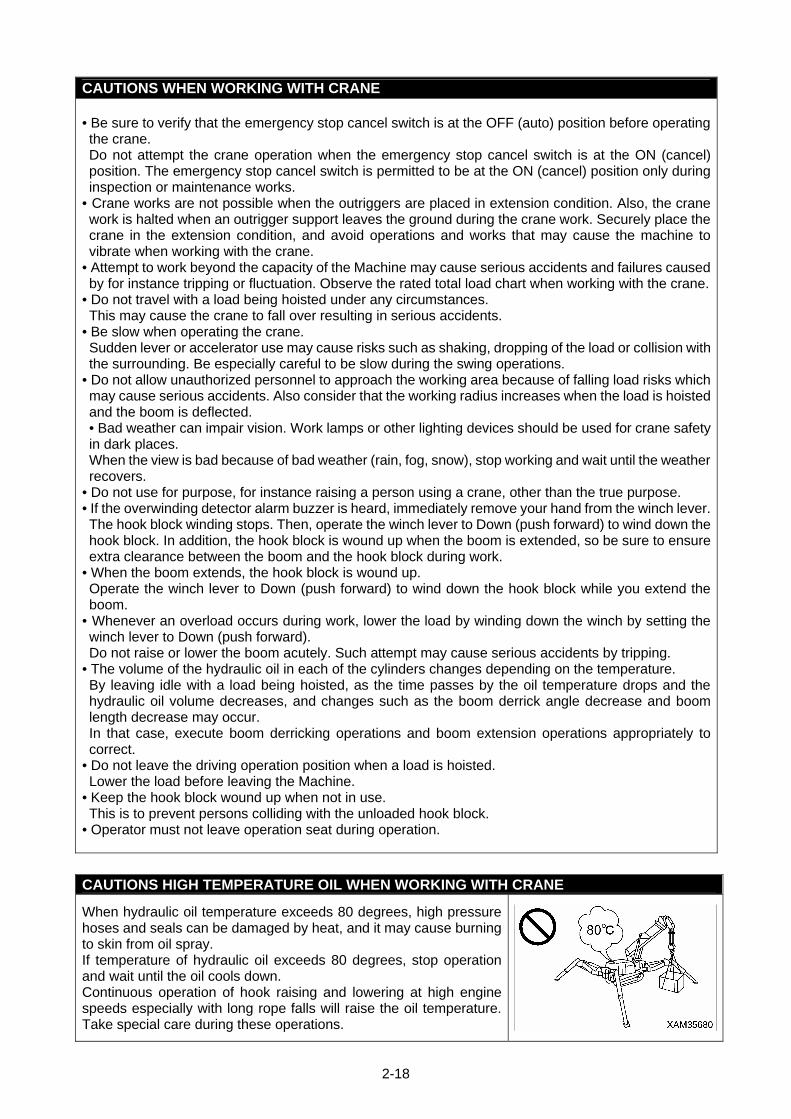
CAUTIONS HIGH TEMPERATURE OIL WHEN WORKING WITH CRANE
When hydraulic oil temperature exceeds 80 degrees, high pressure hoses and seals can be damaged by heat, and it may cause burning to skin from oil spray. If temperature of hydraulic oil exceeds 80 degrees, stop operation and wait until the oil cools down. Continuous operation of hook raising and lowering at high engine speeds especially with long rope falls will raise the oil temperature. Take special care during these operations.
2-19
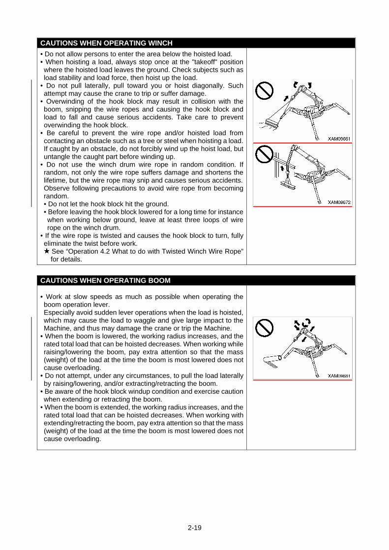
CAUTIONS WHEN OPERATING WINCH
• Do not allow persons to enter the area below the hoisted load. • When hoisting a load, always stop once at the "takeoff" position where the hoisted load leaves the ground. Check subjects such as load stability and load force, then hoist up the load.
• Do not pull laterally, pull toward you or hoist diagonally. Such attempt may cause the crane to trip or suffer damage.
• Overwinding of the hook block may result in collision with the boom, snipping the wire ropes and causing the hook block and load to fall and cause serious accidents. Take care to prevent overwinding the hook block.
• Be careful to prevent the wire rope and/or hoisted load from contacting an obstacle such as a tree or steel when hoisting a load.If caught by an obstacle, do not forcibly wind up the hoist load, but untangle the caught part before winding up.
• Do not use the winch drum wire rope in random condition. If random, not only the wire rope suffers damage and shortens the lifetime, but the wire rope may snip and causes serious accidents.Observe following precautions to avoid wire rope from becoming random. • Do not let the hook block hit the ground. • Before leaving the hook block lowered for a long time for instance when working below ground, leave at least three loops of wire rope on the winch drum.
• If the wire rope is twisted and causes the hook block to turn, fully eliminate the twist before work.
See “Operation 4.2 What to do with Twisted Winch Wire Rope” for details.
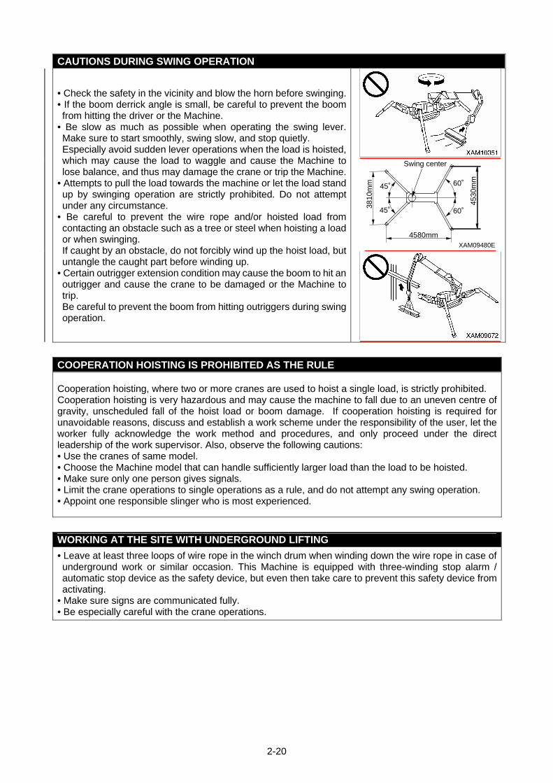
CAUTIONS WHEN OPERATING BOOM
• Work at slow speeds as much as possible when operating the boom operation lever. Especially avoid sudden lever operations when the load is hoisted, which may cause the load to waggle and give large impact to the Machine, and thus may damage the crane or trip the Machine.
• When the boom is lowered, the working radius increases, and the rated total load that can be hoisted decreases. When working while raising/lowering the boom, pay extra attention so that the mass (weight) of the load at the time the boom is most lowered does not cause overloading.
• Do not attempt, under any circumstances, to pull the load laterally by raising/lowering, and/or extracting/retracting the boom.
• Be aware of the hook block windup condition and exercise caution when extending or retracting the boom.
• When the boom is extended, the working radius increases, and the rated total load that can be hoisted decreases. When working with extending/retracting the boom, pay extra attention so that the mass (weight) of the load at the time the boom is most lowered does not cause overloading.
2-20
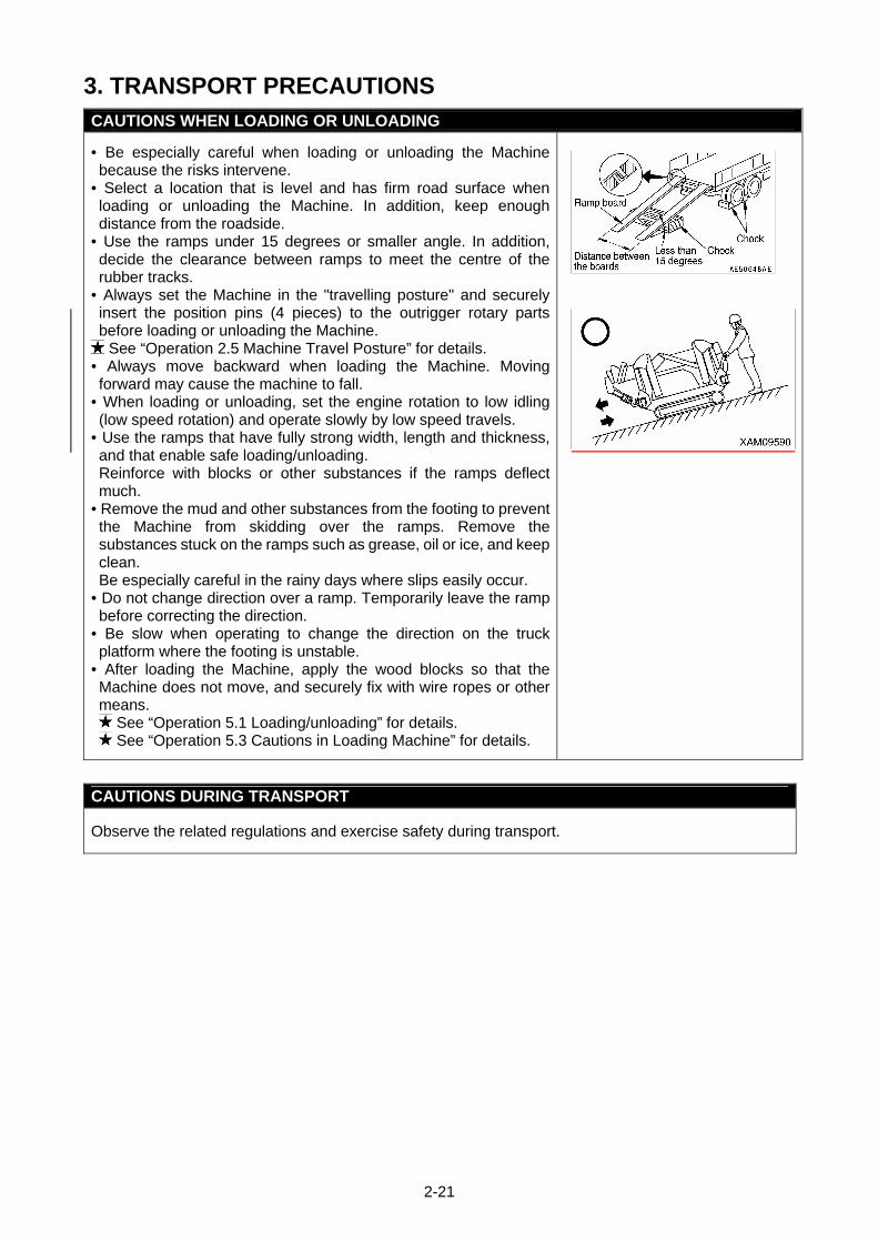
CAUTIONS DURING SWING OPERATION
• Check the safety in the vicinity and blow the horn before swinging.• If the boom derrick angle is small, be careful to prevent the boom from hitting the driver or the Machine.
• Be slow as much as possible when operating the swing lever. Make sure to start smoothly, swing slow, and stop quietly. Especially avoid sudden lever operations when the load is hoisted, which may cause the load to waggle and cause the Machine to lose balance, and thus may damage the crane or trip the Machine.
• Attempts to pull the load towards the machine or let the load stand up by swinging operation are strictly prohibited. Do not attempt under any circumstance.
• Be careful to prevent the wire rope and/or hoisted load from contacting an obstacle such as a tree or steel when hoisting a load or when swinging. If caught by an obstacle, do not forcibly wind up the hoist load, but untangle the caught part before winding up.
• Certain outrigger extension condition may cause the boom to hit an outrigger and cause the crane to be damaged or the Machine to trip. Be careful to prevent the boom from hitting outriggers during swing operation.
XAM09480E
4530
mm
3810
mm
4580mm
Swing center
45˚ 60˚
60˚45˚
COOPERATION HOISTING IS PROHIBITED AS THE RULE
Cooperation hoisting, where two or more cranes are used to hoist a single load, is strictly prohibited. Cooperation hoisting is very hazardous and may cause the machine to fall due to an uneven centre of gravity, unscheduled fall of the hoist load or boom damage. If cooperation hoisting is required for unavoidable reasons, discuss and establish a work scheme under the responsibility of the user, let the worker fully acknowledge the work method and procedures, and only proceed under the direct leadership of the work supervisor. Also, observe the following cautions: • Use the cranes of same model. • Choose the Machine model that can handle sufficiently larger load than the load to be hoisted. • Make sure only one person gives signals. • Limit the crane operations to single operations as a rule, and do not attempt any swing operation. • Appoint one responsible slinger who is most experienced.
WORKING AT THE SITE WITH UNDERGROUND LIFTING
• Leave at least three loops of wire rope in the winch drum when winding down the wire rope in case of underground work or similar occasion. This Machine is equipped with three-winding stop alarm / automatic stop device as the safety device, but even then take care to prevent this safety device from activating.
• Make sure signs are communicated fully. • Be especially careful with the crane operations.
2-21
3. TRANSPORT PRECAUTIONS CAUTIONS WHEN LOADING OR UNLOADING
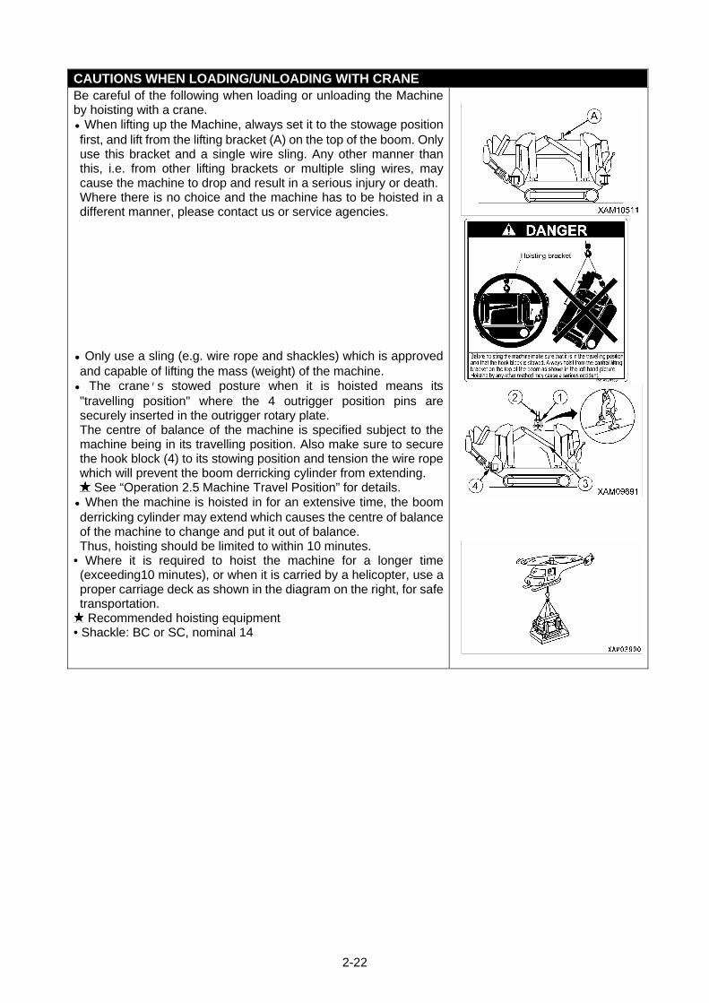
• Be especially careful when loading or unloading the Machine because the risks intervene.
• Select a location that is level and has firm road surface when loading or unloading the Machine. In addition, keep enough distance from the roadside.
• Use the ramps under 15 degrees or smaller angle. In addition, decide the clearance between ramps to meet the centre of the rubber tracks.
• Always set the Machine in the "travelling posture" and securely insert the position pins (4 pieces) to the outrigger rotary parts before loading or unloading the Machine. See “Operation 2.5 Machine Travel Posture” for details.
• Always move backward when loading the Machine. Moving forward may cause the machine to fall.
• When loading or unloading, set the engine rotation to low idling (low speed rotation) and operate slowly by low speed travels.
• Use the ramps that have fully strong width, length and thickness, and that enable safe loading/unloading. Reinforce with blocks or other substances if the ramps deflect much.
• Remove the mud and other substances from the footing to prevent the Machine from skidding over the ramps. Remove the substances stuck on the ramps such as grease, oil or ice, and keep clean. Be especially careful in the rainy days where slips easily occur.
• Do not change direction over a ramp. Temporarily leave the ramp before correcting the direction.
• Be slow when operating to change the direction on the truck platform where the footing is unstable.
• After loading the Machine, apply the wood blocks so that the Machine does not move, and securely fix with wire ropes or other means.
See “Operation 5.1 Loading/unloading” for details. See “Operation 5.3 Cautions in Loading Machine” for details.
CAUTIONS DURING TRANSPORT
Observe the related regulations and exercise safety during transport.
2-22
CAUTIONS WHEN LOADING/UNLOADING WITH CRANE Be careful of the following when loading or unloading the Machine by hoisting with a crane. • When lifting up the Machine, always set it to the stowage position first, and lift from the lifting bracket (A) on the top of the boom. Only use this bracket and a single wire sling. Any other manner than this, i.e. from other lifting brackets or multiple sling wires, may cause the machine to drop and result in a serious injury or death. Where there is no choice and the machine has to be hoisted in a different manner, please contact us or service agencies.
• Only use a sling (e.g. wire rope and shackles) which is approved and capable of lifting the mass (weight) of the machine.
• The crane’s stowed posture when it is hoisted means its "travelling position" where the 4 outrigger position pins are securely inserted in the outrigger rotary plate. The centre of balance of the machine is specified subject to the machine being in its travelling position. Also make sure to secure the hook block (4) to its stowing position and tension the wire rope which will prevent the boom derricking cylinder from extending.
See “Operation 2.5 Machine Travel Position” for details. • When the machine is hoisted in for an extensive time, the boom derricking cylinder may extend which causes the centre of balance of the machine to change and put it out of balance. Thus, hoisting should be limited to within 10 minutes.
• Where it is required to hoist the machine for a longer time (exceeding10 minutes), or when it is carried by a helicopter, use a proper carriage deck as shown in the diagram on the right, for safe transportation. Recommended hoisting equipment
• Shackle: BC or SC, nominal 14
2-23
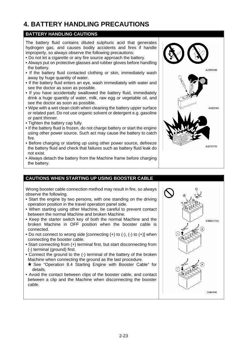
4. BATTERY HANDLING PRECAUTIONS BATTERY HANDLING CAUTIONS
The battery fluid contains diluted sulphuric acid that generates hydrogen gas, and causes bodily accidents and fires if handle improperly, so always observe the following precautions: • Do not let a cigarette or any fire source approach the battery. • Always put on protective glasses and rubber gloves before handling the battery.
• If the battery fluid contacted clothing or skin, immediately wash away by huge quantity of water.
• If the battery fluid enters an eye, wash immediately with water and see the doctor as soon as possible.
• If you have accidentally swallowed the battery fluid, immediately drink a huge quantity of water, milk, raw egg or vegetable oil, and see the doctor as soon as possible.
• Wipe with a wet clean cloth when cleaning the battery upper surface or related part. Do not use organic solvent or detergent e.g. gasoline or paint thinner.
• Tighten the battery cap fully. • If the battery fluid is frozen, do not charge battery or start the engine using other power source. Such act may cause the battery to catch fire.
• Before charging or starting up using other power source, defreeze the battery fluid and check that failures such as battery fluid leak do not exist.
• Always detach the battery from the Machine frame before charging the battery.
CAUTIONS WHEN STARTING UP USING BOOSTER CABLE Wrong booster cable connection method may result in fire, so always observe the following. • Start the engine by two persons, with one standing on the driving operation position in the travel operation panel side.
• When starting using other Machine, be careful to prevent contact between the normal Machine and broken Machine.
• Keep the starter switch key of both the normal Machine and the broken Machine in OFF position when the booster cable is connected.
• Do not connect to wrong side [connecting (+) to (-), (-) to (+)] when connecting the booster cable.
• Start connecting from (+) terminal first, but start disconnecting from (-) terminal (ground) first.
• Connect the ground to the (-) terminal of the battery of the broken Machine when connecting the ground as the last procedure.
See “Operation 8.4 Starting Engine with Booster Cable” for details.
• Avoid the contact between clips of the booster cable, and contact between a clip and the Machine when disconnecting the booster cable.
2-24
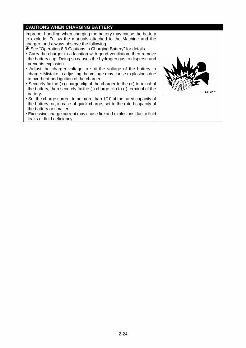
CAUTIONS WHEN CHARGING BATTERY
Improper handling when charging the battery may cause the battery to explode. Follow the manuals attached to the Machine and the charger, and always observe the following.
See “Operation 8.3 Cautions in Charging Battery” for details. • Carry the charger to a location with good ventilation, then remove the battery cap. Doing so causes the hydrogen gas to disperse and prevents explosion.
• Adjust the charger voltage to suit the voltage of the battery to charge. Mistake in adjusting the voltage may cause explosions due to overheat and ignition of the charger.
• Securely fix the (+) charge clip of the charger to the (+) terminal of the battery, then securely fix the (-) charge clip to (-) terminal of the battery.
• Set the charge current to no more than 1/10 of the rated capacity of the battery, or, in case of quick charge, set to the rated capacity of the battery or smaller.
• Excessive charge current may cause fire and explosions due to fluid leaks or fluid deficiency.
2-25
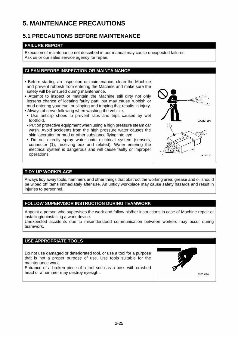
5. MAINTENANCE PRECAUTIONS
5.1 PRECAUTIONS BEFORE MAINTENANCE
FAILURE REPORT
Execution of maintenance not described in our manual may cause unexpected failures. Ask us or our sales service agency for repair.
CLEAN BEFORE INSPECTION OR MAINTAINANCE
• Before starting an inspection or maintenance, clean the Machine and prevent rubbish from entering the Machine and make sure the safety will be ensured during maintenance.
• Attempt to inspect or maintain the Machine still dirty not only lessens chance of locating faulty part, but may cause rubbish or mud entering your eye, or slipping and tripping that results in injury.
• Always observe following when washing the vehicle. • Use antislip shoes to prevent slips and trips caused by wet foothold.
• Put on protective equipment when using a high pressure steam car wash. Avoid accidents from the high pressure water causes the skin laceration or mud or other substance flying into eye.
• Do not directly spray water onto electrical system (sensors, connector (1), receiving box and related). Water entering the electrical system is dangerous and will cause faulty or improper operations.
TIDY UP WORKPLACE
Always tidy away tools, hammers and other things that obstruct the working area; grease and oil should be wiped off items immediately after use. An untidy workplace may cause safety hazards and result in injuries to personnel.
FOLLOW SUPERVISOR INSTRUCTION DURING TEAMWORK
Appoint a person who supervises the work and follow his/her instructions in case of Machine repair or installing/uninstalling a work device. Unexpected accidents due to misunderstood communication between workers may occur during teamwork.
USE APPROPRIATE TOOLS
Do not use damaged or deteriorated tool, or use a tool for a purpose that is not a proper purpose of use. Use tools suitable for the maintenance work. Entrance of a broken piece of a tool such as a boss with crashed head or a hammer may destroy eyesight.
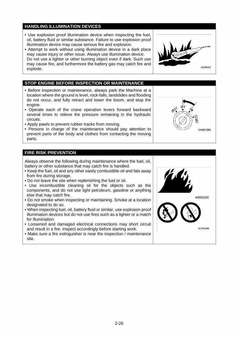
2-26
HANDLING ILLUMINATION DEVICES
• Use explosion proof illumination device when inspecting the fuel, oil, battery fluid or similar substance. Failure to use explosion proof illumination device may cause serious fire and explosion.
• Attempt to work without using illumination device in a dark place may cause injury or other issue. Always use illumination device. Do not use a lighter or other burning object even if dark. Such use may cause fire, and furthermore the battery gas may catch fire and explode.
STOP ENGINE BEFORE INSPECTION OR MAINTENANCE
• Before inspection or maintenance, always park the Machine at a location where the ground is level, rock-falls, landslides and flooding do not occur, and fully retract and lower the boom, and stop the engine.
• Operate each of the crane operation levers forward backward several times to relieve the pressure remaining in the hydraulic circuits.
• Apply pawls to prevent rubber tracks from moving. • Persons in charge of the maintenance should pay attention to prevent parts of the body and clothes from contacting the moving parts.
FIRE RISK PREVENTION
Always observe the following during maintenance where the fuel, oil, battery or other substance that may catch fire is handled. • Keep the fuel, oil and any other easily combustible oil and fats away from fire during storage.
• Do not leave the site when replenishing the fuel or oil. • Use incombustible cleaning oil for the objects such as the components, and do not use light petroleum, gasoline or anything else that may catch fire.
• Do not smoke when inspecting or maintaining. Smoke at a location designated to do so.
• When inspecting fuel, oil, battery fluid or similar, use explosion proof illumination devices but do not use fires such as a lighter or a match for illumination.
• Loosened and damaged electrical connections may short circuit and result in a fire. Inspect accordingly before starting work.
• Make sure a fire extinguisher is near the inspection / maintenance site.
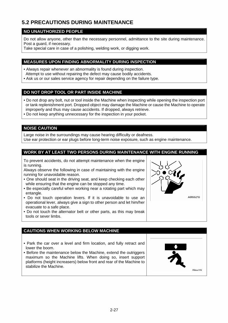
2-27
5.2 PRECAUTIONS DURING MAINTENANCE
NO UNAUTHORIZED PEOPLE
Do not allow anyone, other than the necessary personnel, admittance to the site during maintenance. Post a guard, if necessary. Take special care in case of a polishing, welding work, or digging work.
MEASURES UPON FINDING ABNORMALITY DURING INSPECTION
• Always repair whenever an abnormality is found during inspection. Attempt to use without repairing the defect may cause bodily accidents.
• Ask us or our sales service agency for repair depending on the failure type.
DO NOT DROP TOOL OR PART INSIDE MACHINE
• Do not drop any bolt, nut or tool inside the Machine when inspecting while opening the inspection port or tank replenishment port. Dropped object may damage the Machine or cause the Machine to operate improperly and thus may cause accidents. If dropped, always retrieve.
• Do not keep anything unnecessary for the inspection in your pocket.
NOISE CAUTION
Large noise in the surroundings may cause hearing difficulty or deafness. Use ear protection or ear plugs before long-term noise exposure, such as engine maintenance.
WORK BY AT LEAST TWO PERSONS DURING MAINTENANCE WITH ENGINE RUNNING
To prevent accidents, do not attempt maintenance when the engine is running. Always observe the following in case of maintaining with the engine running for unavoidable reason. • One should seat in the driving seat, and keep checking each other while ensuring that the engine can be stopped any time.
• Be especially careful when working near a rotating part which may entangle.
• Do not touch operation levers. If it is unavoidable to use an operational lever, always give a sign to other person and let him/her evacuate to a safe place.
• Do not touch the alternator belt or other parts, as this may break tools or sever limbs.
CAUTIONS WHEN WORKING BELOW MACHINE
• Park the car over a level and firm location, and fully retract and lower the boom.
• Before the maintenance below the Machine, extend the outriggers maximum so the Machine lifts. When doing so, insert support platforms (height increasers) below front and rear of the Machine to stabilize the Machine.
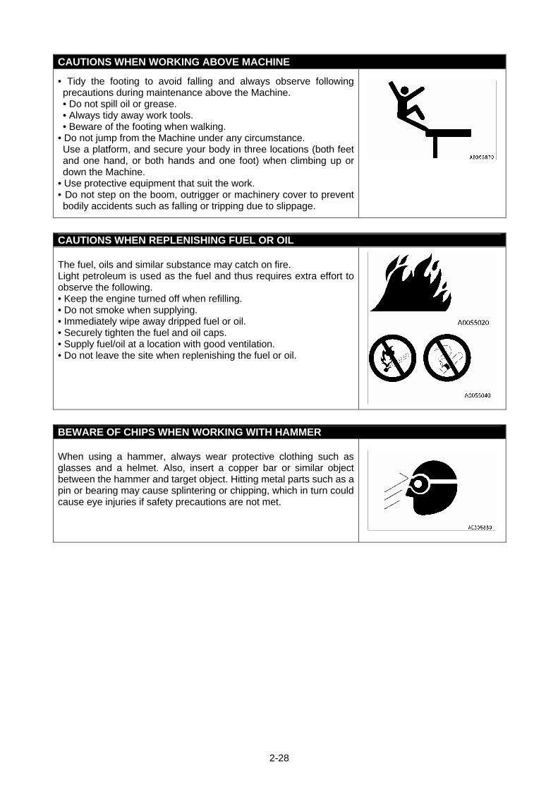
2-28
CAUTIONS WHEN WORKING ABOVE MACHINE
• Tidy the footing to avoid falling and always observe following precautions during maintenance above the Machine. • Do not spill oil or grease. • Always tidy away work tools. • Beware of the footing when walking.
• Do not jump from the Machine under any circumstance. Use a platform, and secure your body in three locations (both feet and one hand, or both hands and one foot) when climbing up or down the Machine.
• Use protective equipment that suit the work. • Do not step on the boom, outrigger or machinery cover to prevent bodily accidents such as falling or tripping due to slippage.
CAUTIONS WHEN REPLENISHING FUEL OR OIL The fuel, oils and similar substance may catch on fire. Light petroleum is used as the fuel and thus requires extra effort to observe the following. • Keep the engine turned off when refilling. • Do not smoke when supplying. • Immediately wipe away dripped fuel or oil. • Securely tighten the fuel and oil caps. • Supply fuel/oil at a location with good ventilation. • Do not leave the site when replenishing the fuel or oil.
BEWARE OF CHIPS WHEN WORKING WITH HAMMER When using a hammer, always wear protective clothing such as glasses and a helmet. Also, insert a copper bar or similar object between the hammer and target object. Hitting metal parts such as a pin or bearing may cause splintering or chipping, which in turn could cause eye injuries if safety precautions are not met.
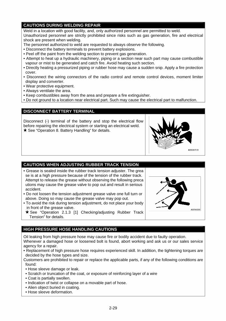
2-29
CAUTIONS DURING WELDING REPAIR Weld in a location with good facility, and, only authorized personnel are permitted to weld. Unauthorized personnel are strictly prohibited since risks such as gas generation, fire and electrical shock are present when welding. The personnel authorized to weld are requested to always observe the following. • Disconnect the battery terminals to prevent battery explosions. • Peel off the paint from the welding section to prevent gas generation. • Attempt to heat up a hydraulic machinery, piping or a section near such part may cause combustible vapour or mist to be generated and catch fire. Avoid heating such section.
• Directly heating a pressurized piping or rubber hose may cause a sudden snip. Apply a fire protection cover.
• Disconnect the wiring connectors of the radio control and remote control devices, moment limiter display and converter.
• Wear protective equipment. • Always ventilate the area. • Keep combustibles away from the area and prepare a fire extinguisher. • Do not ground to a location near electrical part. Such may cause the electrical part to malfunction.
DISCONNECT BATTERY TERMINAL Disconnect (-) terminal of the battery and stop the electrical flow before repairing the electrical system or starting an electrical weld.
See “Operation 8. Battery Handling” for details.
CAUTIONS WHEN ADJUSTING RUBBER TRACK TENSION
• Grease is sealed inside the rubber track tension adjuster. The grease is at a high pressure because of the tension of the rubber track. Attempt to release the grease without observing the following precautions may cause the grease valve to pop out and result in serious accident.
• Do not loosen the tension adjustment grease valve one full turn or above. Doing so may cause the grease valve may pop out.
• To avoid the risk during tension adjustment, do not place your body in front of the grease valve.
See “Operation 2.1.3 [1] Checking/adjusting Rubber Track Tension” for details.
HIGH PRESSURE HOSE HANDLING CAUTIONS
Oil leaking from high pressure hose may cause fire or bodily accident due to faulty operation. Whenever a damaged hose or loosened bolt is found, abort working and ask us or our sales service agency for a repair. • Replacement of high pressure hose requires experienced skill. In addition, the tightening torques are decided by the hose types and size.
Customers are prohibited to repair or replace the applicable parts, if any of the following conditions are found: • Hose sleeve damage or leak. • Scratch or truncation of the coat, or exposure of reinforcing layer of a wire • Coat is partially swollen. • Indication of twist or collapse on a movable part of hose. • Alien object buried in coating. • Hose sleeve deformation.
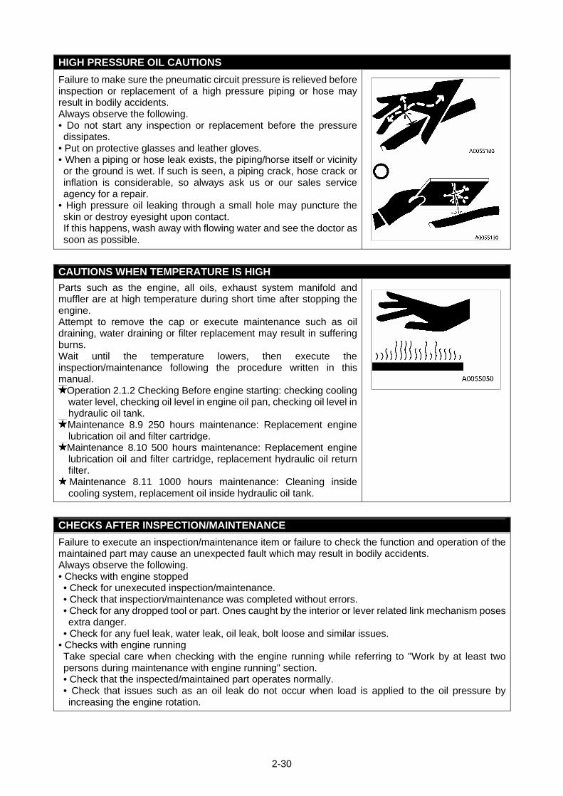
2-30
HIGH PRESSURE OIL CAUTIONS
Failure to make sure the pneumatic circuit pressure is relieved before inspection or replacement of a high pressure piping or hose may result in bodily accidents. Always observe the following. • Do not start any inspection or replacement before the pressure dissipates.
• Put on protective glasses and leather gloves. • When a piping or hose leak exists, the piping/horse itself or vicinity or the ground is wet. If such is seen, a piping crack, hose crack or inflation is considerable, so always ask us or our sales service agency for a repair.
• High pressure oil leaking through a small hole may puncture the skin or destroy eyesight upon contact. If this happens, wash away with flowing water and see the doctor as soon as possible.
CAUTIONS WHEN TEMPERATURE IS HIGH
Parts such as the engine, all oils, exhaust system manifold and muffler are at high temperature during short time after stopping the engine. Attempt to remove the cap or execute maintenance such as oil draining, water draining or filter replacement may result in suffering burns. Wait until the temperature lowers, then execute the inspection/maintenance following the procedure written in this manual.
Operation 2.1.2 Checking Before engine starting: checking cooling water level, checking oil level in engine oil pan, checking oil level in hydraulic oil tank. Maintenance 8.9 250 hours maintenance: Replacement engine lubrication oil and filter cartridge. Maintenance 8.10 500 hours maintenance: Replacement engine lubrication oil and filter cartridge, replacement hydraulic oil return filter. Maintenance 8.11 1000 hours maintenance: Cleaning inside cooling system, replacement oil inside hydraulic oil tank.
CHECKS AFTER INSPECTION/MAINTENANCE
Failure to execute an inspection/maintenance item or failure to check the function and operation of the maintained part may cause an unexpected fault which may result in bodily accidents. Always observe the following. • Checks with engine stopped • Check for unexecuted inspection/maintenance. • Check that inspection/maintenance was completed without errors. • Check for any dropped tool or part. Ones caught by the interior or lever related link mechanism poses extra danger.
• Check for any fuel leak, water leak, oil leak, bolt loose and similar issues. • Checks with engine running Take special care when checking with the engine running while referring to "Work by at least two persons during maintenance with engine running" section. • Check that the inspected/maintained part operates normally. • Check that issues such as an oil leak do not occur when load is applied to the oil pressure by increasing the engine rotation.

2-31
CAUTIONS WHEN TREATING WASTE
To prevent environmental pollution, observe the following: • Never allow waste oil to flow into water systems, such as river or sewage system.
• Always drain into a container when draining the oil from the Machine. Do not directly drain to the ground.
• Observe the applicable legal regulations and rules when disposing harmful substance such as the oil, fuel, solvent, filter or battery.
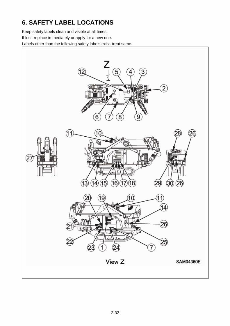
2-32
6. SAFETY LABEL LOCATIONS Keep safety labels clean and visible at all times.
If lost, replace immediately or apply for a new one.
Labels other than the following safety labels exist. treat same.
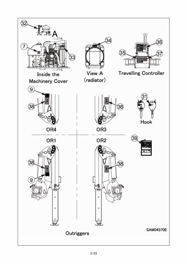
2-33
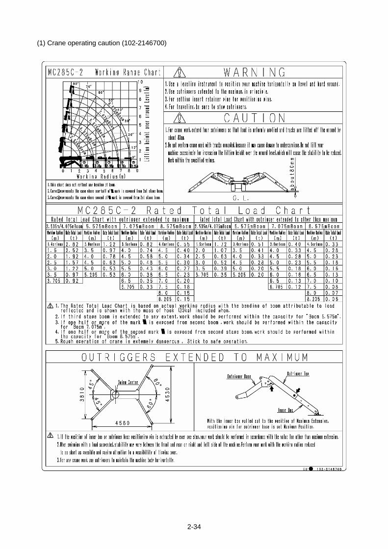
2-34
(1) Crane operating caution (102-2146700)
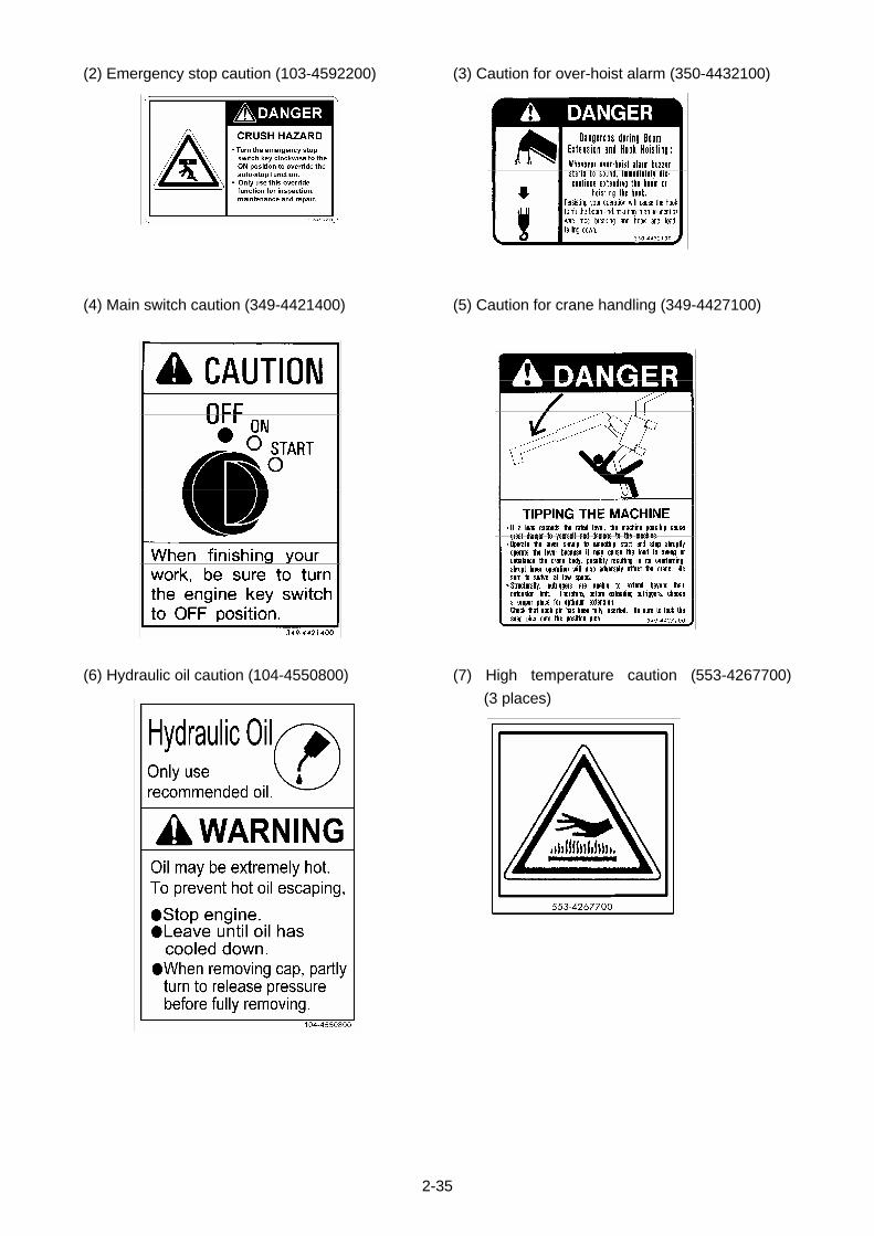
2-35
(2) Emergency stop caution (103-4592200)
(4) Main switch caution (349-4421400)
(6) Hydraulic oil caution (104-4550800)
(3) Caution for over-hoist alarm (350-4432100)
(5) Caution for crane handling (349-4427100)
(7) High temperature caution (553-4267700)
(3 places)
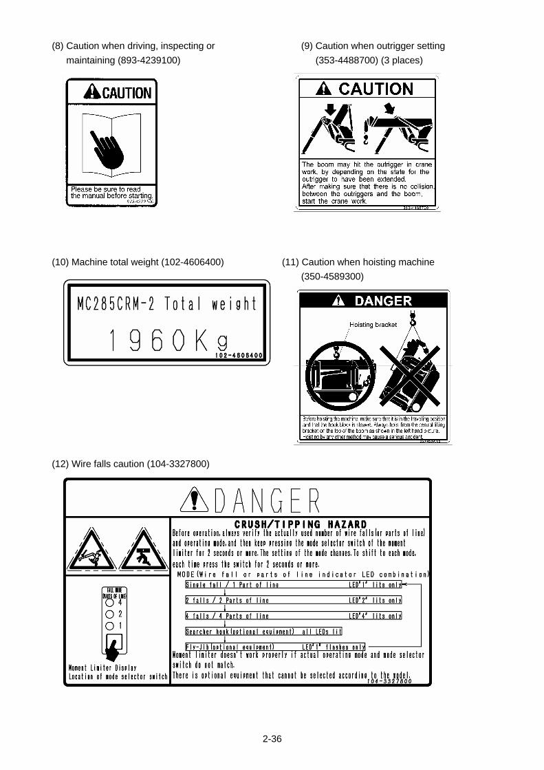
2-36
(8) Caution when driving, inspecting or
maintaining (893-4239100)
(10) Machine total weight (102-4606400)
(12) Wire falls caution (104-3327800)
(9) Caution when outrigger setting
(353-4488700) (3 places)
(11) Caution when hoisting machine
(350-4589300)

2-37
(13) Winch caution (553-4267500)
(15) Rotating fan caution (349-4526900)
(17) Warning (553-4268000)
(14) No access to crane (349-4422000)
(16) Electric shock caution (553-4267300)
(18) Pinch caution (553-4267600)
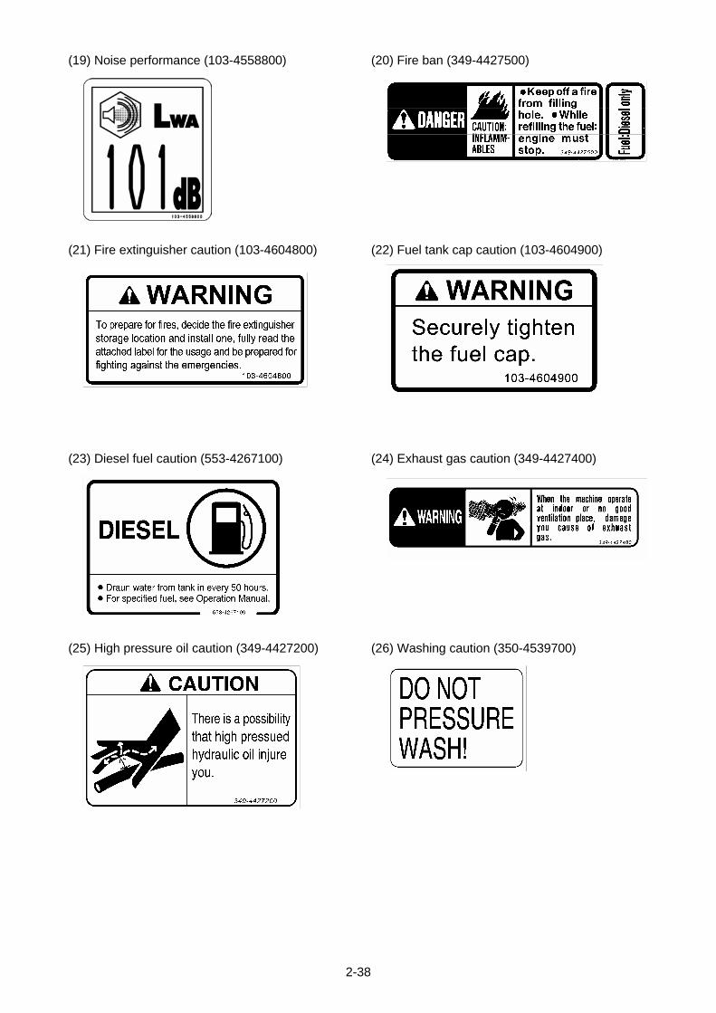
2-38
(19) Noise performance (103-4558800)
(21) Fire extinguisher caution (103-4604800)
(23) Diesel fuel caution (553-4267100)
(25) High pressure oil caution (349-4427200)
(20) Fire ban (349-4427500)
(22) Fuel tank cap caution (103-4604900)
(24) Exhaust gas caution (349-4427400)
(26) Washing caution (350-4539700)
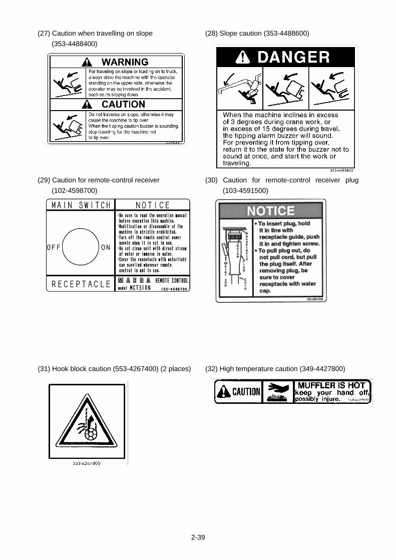
2-39
(27) Caution when travelling on slope
(353-4488400)
(29) Caution for remote-control receiver
(102-4598700)
(31) Hook block caution (553-4267400) (2 places)
(28) Slope caution (353-4488600)
(30) Caution for remote-control receiver plug
(103-4591500)
(32) High temperature caution (349-4427800)
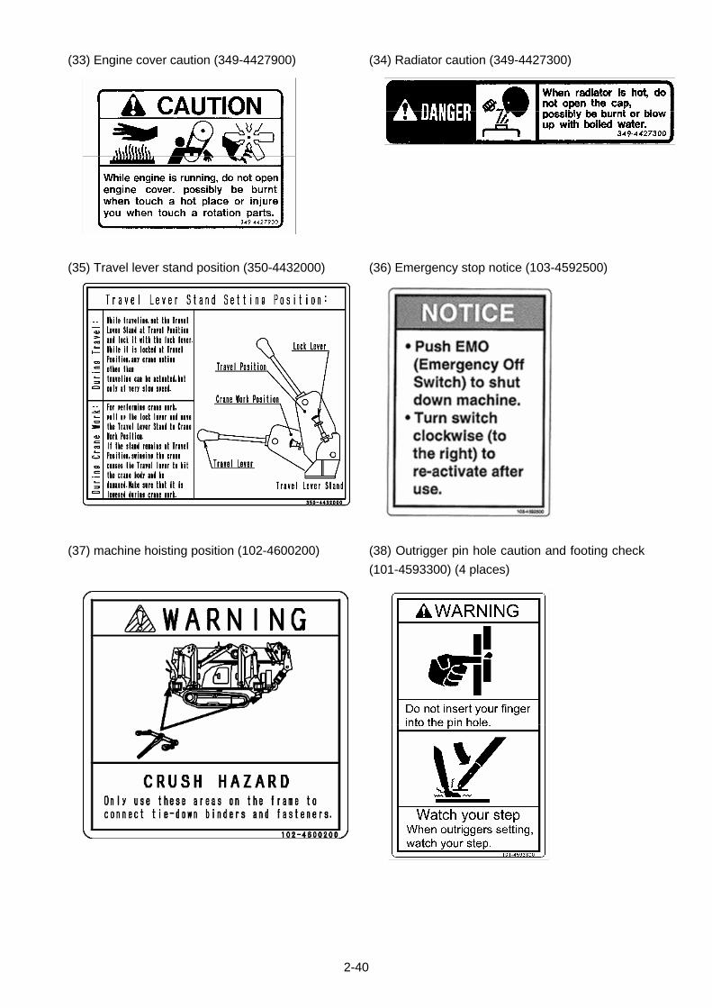
2-40
(33) Engine cover caution (349-4427900)
(35) Travel lever stand position (350-4432000)
(37) machine hoisting position (102-4600200)
(34) Radiator caution (349-4427300)
(36) Emergency stop notice (103-4592500)
(38) Outrigger pin hole caution and footing check
(101-4593300) (4 places)
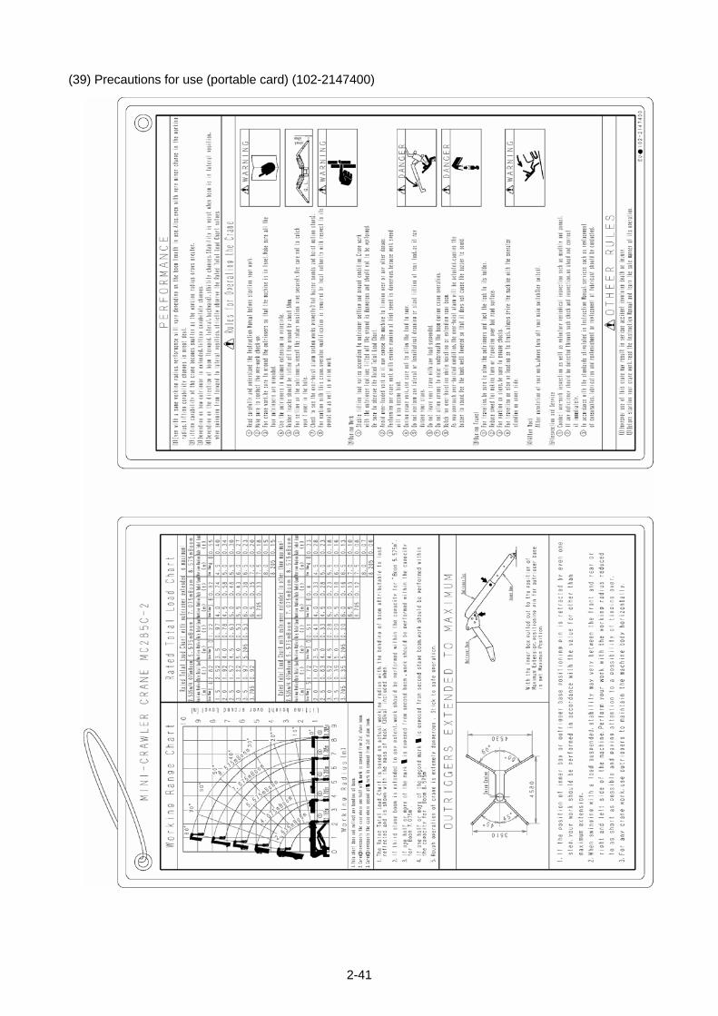
2-41
(39) Precautions for use (portable card) (102-2147400)

2-42

3-1
OPERATION
1. MACHINE EACH SECTION 3- 2
2. OPERATIONS 3-37
3. HANDLING RUBBER TRACKS 3-90
4. HANDLING WIRE ROPES 3-94
5. TRANSPORTATION 3-96
6. HANDLING IN COLD WEATHER 3-99
7. LONG-TERM STORAGE 3-101
8. HANDLING BATTERY 3-102
9. TROUBLESHOOTING 3-107
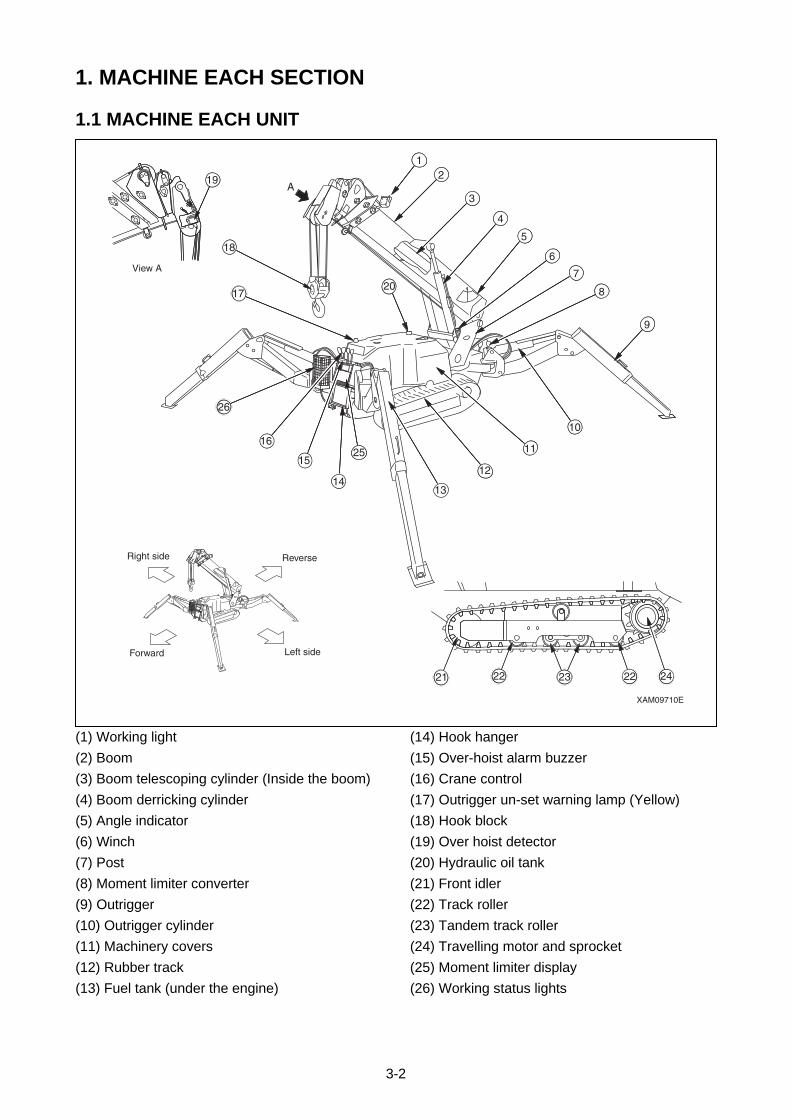
3-2
1. MACHINE EACH SECTION
1.1 MACHINE EACH UNIT
(1) Working light
(2) Boom
(3) Boom telescoping cylinder (Inside the boom)
(4) Boom derricking cylinder
(5) Angle indicator
(6) Winch
(7) Post
(8) Moment limiter converter
(9) Outrigger
(10) Outrigger cylinder
(11) Machinery covers
(12) Rubber track
(13) Fuel tank (under the engine)
(14) Hook hanger
(15) Over-hoist alarm buzzer
(16) Crane control
(17) Outrigger un-set warning lamp (Yellow)
(18) Hook block
(19) Over hoist detector
(20) Hydraulic oil tank
(21) Front idler
(22) Track roller
(23) Tandem track roller
(24) Travelling motor and sprocket
(25) Moment limiter display
(26) Working status lights
12
3
4
5
6
7
8
9
10
11
12
1314
2515
16
17
26
18
19
20
A
XAM09710E
Reverse
Left side
Right side
Forward
2422232221
View A
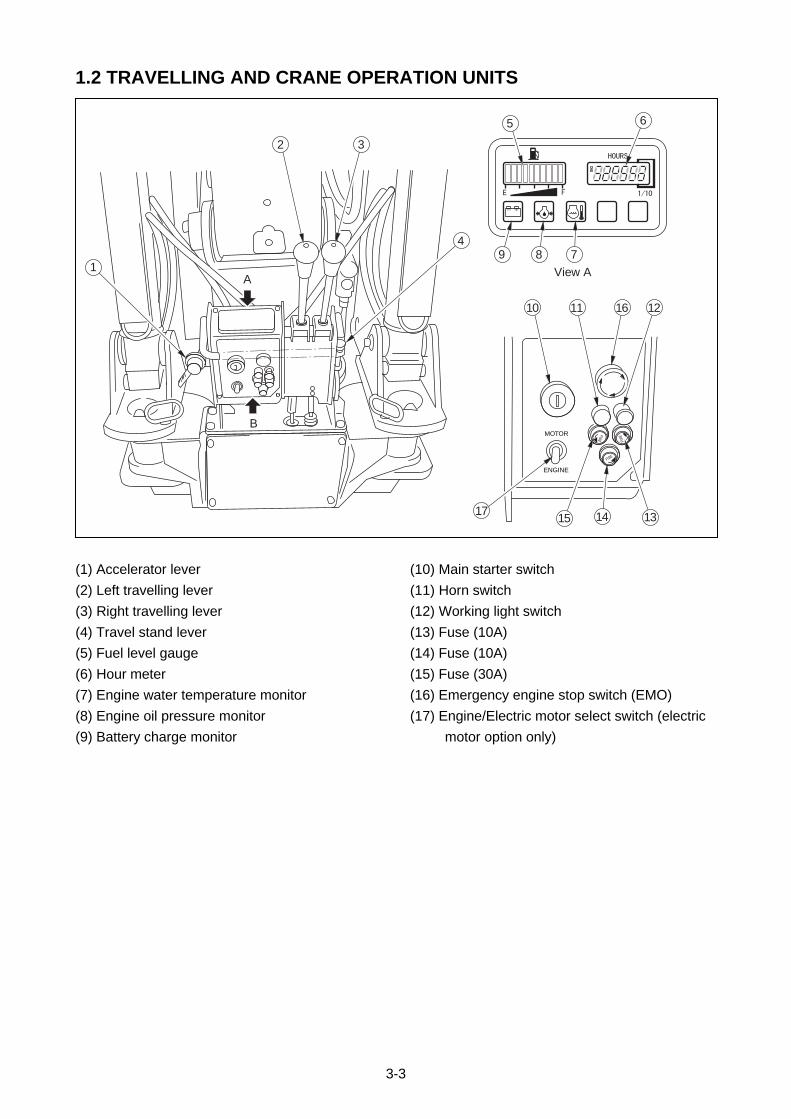
3-3
1.2 TRAVELLING AND CRANE OPERATION UNITS
(1) Accelerator lever
(2) Left travelling lever
(3) Right travelling lever
(4) Travel stand lever
(5) Fuel level gauge
(6) Hour meter
(7) Engine water temperature monitor
(8) Engine oil pressure monitor
(9) Battery charge monitor
(10) Main starter switch
(11) Horn switch
(12) Working light switch
(13) Fuse (10A)
(14) Fuse (10A)
(15) Fuse (30A)
(16) Emergency engine stop switch (EMO)
(17) Engine/Electric motor select switch (electric
motor option only)
A
B
1
2
5 6
78
3
49
10 11 1216
1517 14 13
View B
View A
MOTOR
ENGINE
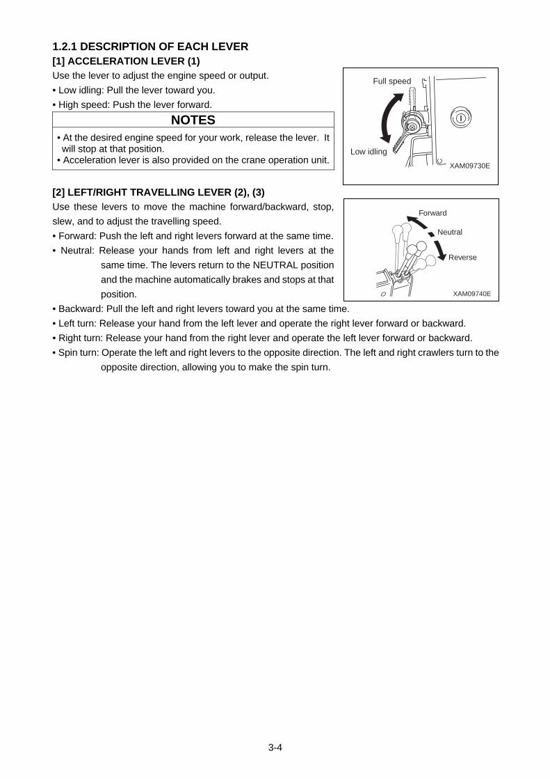
3-4
1.2.1 DESCRIPTION OF EACH LEVER [1] ACCELERATION LEVER (1)
Use the lever to adjust the engine speed or output.
• Low idling: Pull the lever toward you.
• High speed: Push the lever forward.
NOTES
• At the desired engine speed for your work, release the lever. It will stop at that position.
• Acceleration lever is also provided on the crane operation unit.
[2] LEFT/RIGHT TRAVELLING LEVER (2), (3)
Use these levers to move the machine forward/backward, stop,
slew, and to adjust the travelling speed.
• Forward: Push the left and right levers forward at the same time.
• Neutral: Release your hands from left and right levers at the
same time. The levers return to the NEUTRAL position
and the machine automatically brakes and stops at that
position.
• Backward: Pull the left and right levers toward you at the same time.
• Left turn: Release your hand from the left lever and operate the right lever forward or backward.
• Right turn: Release your hand from the right lever and operate the left lever forward or backward.
• Spin turn: Operate the left and right levers to the opposite direction. The left and right crawlers turn to the
opposite direction, allowing you to make the spin turn.
XAM09730E
Low idling
Full speed
XAM09740E
Reverse
Forward
Neutral
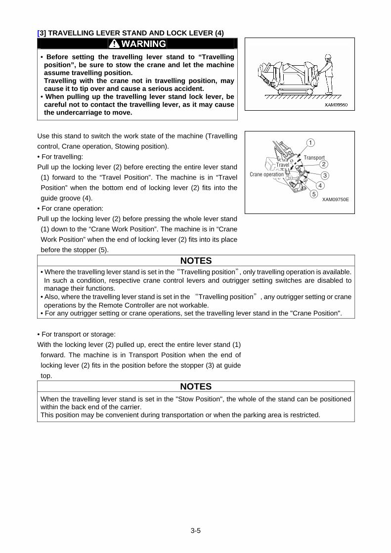
3-5
[3] TRAVELLING LEVER STAND AND LOCK LEVER (4)
• Before setting the travelling lever stand to “Travelling position”, be sure to stow the crane and let the machine assume travelling position. Travelling with the crane not in travelling position, may cause it to tip over and cause a serious accident.
• When pulling up the travelling lever stand lock lever, be careful not to contact the travelling lever, as it may cause the undercarriage to move.
Use this stand to switch the work state of the machine (Travelling
control, Crane operation, Stowing position).
• For travelling:
Pull up the locking lever (2) before erecting the entire lever stand
(1) forward to the “Travel Position”. The machine is in “Travel
Position” when the bottom end of locking lever (2) fits into the
guide groove (4).
• For crane operation:
Pull up the locking lever (2) before pressing the whole lever stand
(1) down to the “Crane Work Position”. The machine is in “Crane
Work Position” when the end of locking lever (2) fits into its place
before the stopper (5).
NOTES
• Where the travelling lever stand is set in the “Travelling position”, only travelling operation is available. In such a condition, respective crane control levers and outrigger setting switches are disabled to manage their functions.
• Also, where the travelling lever stand is set in the “Travelling position”, any outrigger setting or crane operations by the Remote Controller are not workable.
• For any outrigger setting or crane operations, set the travelling lever stand in the "Crane Position".
• For transport or storage:
With the locking lever (2) pulled up, erect the entire lever stand (1)
forward. The machine is in Transport Position when the end of
locking lever (2) fits in the position before the stopper (3) at guide
top.
NOTES
When the travelling lever stand is set in the "Stow Position", the whole of the stand can be positioned within the back end of the carrier. This position may be convenient during transportation or when the parking area is restricted.
XAM09750E
Transport
Crane operation
Travel
1
2
3
45
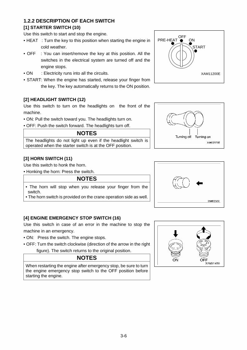
3-6
1.2.2 DESCRIPTION OF EACH SWITCH [1] STARTER SWITCH (10)
Use this switch to start and stop the engine.
• HEAT : Turn the key to this position when starting the engine in
cold weather.
• OFF : You can insert/remove the key at this position. All the
switches in the electrical system are turned off and the
engine stops.
• ON : Electricity runs into all the circuits.
• START: When the engine has started, release your finger from
the key. The key automatically returns to the ON position.
[2] HEADLIGHT SWITCH (12)
Use this switch to turn on the headlights on the front of the
machine.
• ON: Pull the switch toward you. The headlights turn on.
• OFF: Push the switch forward. The headlights turn off.
NOTES
The headlights do not light up even if the headlight switch is operated when the starter switch is at the OFF position.
[3] HORN SWITCH (11)
Use this switch to honk the horn.
• Honking the horn: Press the switch.
NOTES
• The horn will stop when you release your finger from the switch.
• The horn switch is provided on the crane operation side as well.
[4] ENGINE EMERGENCY STOP SWITCH (16)
Use this switch in case of an error in the machine to stop the
machine in an emergency.
• ON: Press the switch. The engine stops.
• OFF: Turn the switch clockwise (direction of the arrow in the right
figure). The switch returns to the original position.
NOTES
When restarting the engine after emergency stop, be sure to turn the engine emergency stop switch to the OFF position before starting the engine.
PRE-HEATOFF
ON
START
XAM11200E
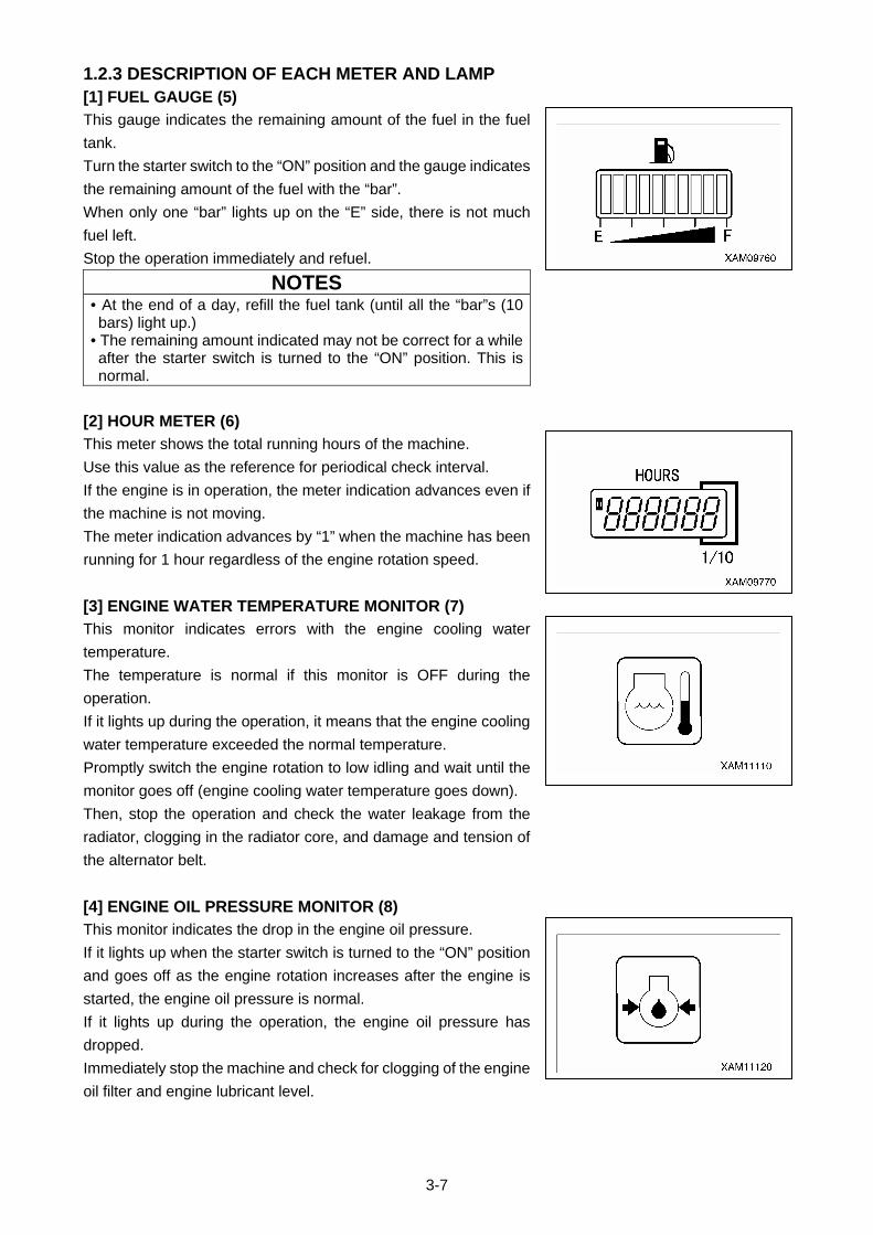
3-7
1.2.3 DESCRIPTION OF EACH METER AND LAMP [1] FUEL GAUGE (5)
This gauge indicates the remaining amount of the fuel in the fuel
tank.
Turn the starter switch to the “ON” position and the gauge indicates
the remaining amount of the fuel with the “bar”.
When only one “bar” lights up on the “E” side, there is not much
fuel left.
Stop the operation immediately and refuel.
NOTES • At the end of a day, refill the fuel tank (until all the “bar”s (10 bars) light up.)
• The remaining amount indicated may not be correct for a while after the starter switch is turned to the “ON” position. This is normal.
[2] HOUR METER (6)
This meter shows the total running hours of the machine.
Use this value as the reference for periodical check interval.
If the engine is in operation, the meter indication advances even if
the machine is not moving.
The meter indication advances by “1” when the machine has been
running for 1 hour regardless of the engine rotation speed.
[3] ENGINE WATER TEMPERATURE MONITOR (7)
This monitor indicates errors with the engine cooling water
temperature.
The temperature is normal if this monitor is OFF during the
operation.
If it lights up during the operation, it means that the engine cooling
water temperature exceeded the normal temperature.
Promptly switch the engine rotation to low idling and wait until the
monitor goes off (engine cooling water temperature goes down).
Then, stop the operation and check the water leakage from the
radiator, clogging in the radiator core, and damage and tension of
the alternator belt.
[4] ENGINE OIL PRESSURE MONITOR (8)
This monitor indicates the drop in the engine oil pressure.
If it lights up when the starter switch is turned to the “ON” position
and goes off as the engine rotation increases after the engine is
started, the engine oil pressure is normal.
If it lights up during the operation, the engine oil pressure has
dropped.
Immediately stop the machine and check for clogging of the engine
oil filter and engine lubricant level.
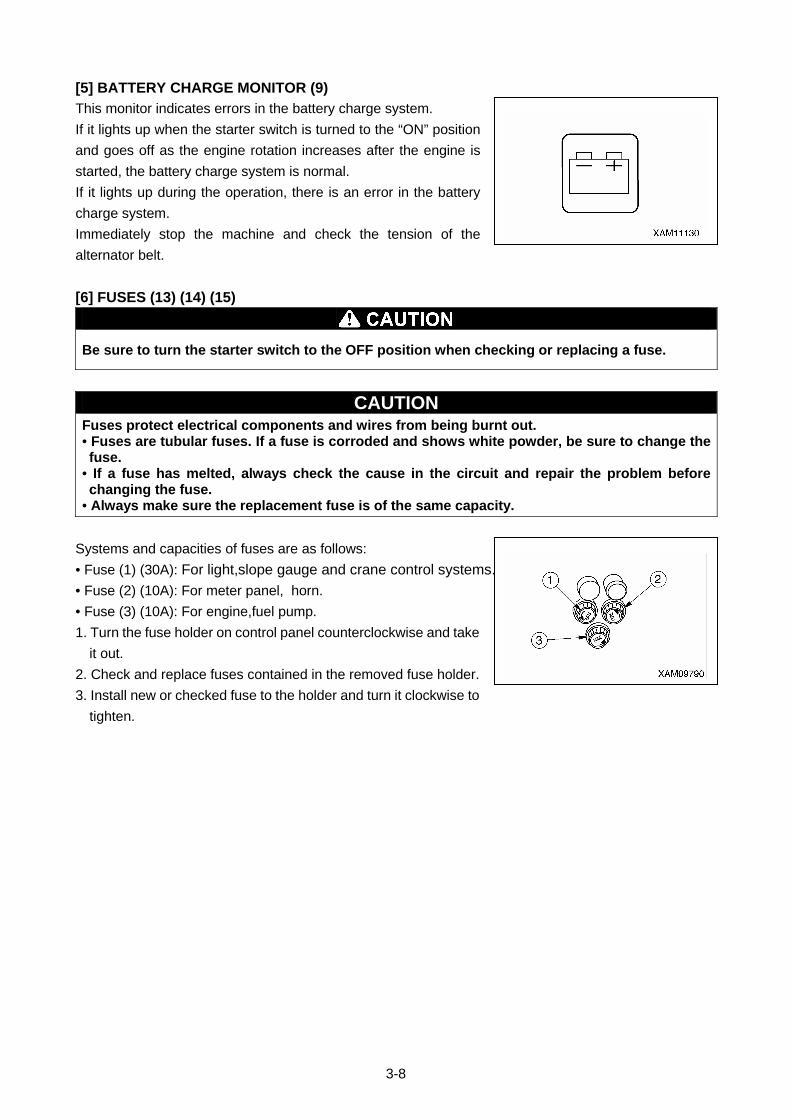
3-8
[5] BATTERY CHARGE MONITOR (9)
This monitor indicates errors in the battery charge system.
If it lights up when the starter switch is turned to the “ON” position
and goes off as the engine rotation increases after the engine is
started, the battery charge system is normal.
If it lights up during the operation, there is an error in the battery
charge system.
Immediately stop the machine and check the tension of the
alternator belt.
[6] FUSES (13) (14) (15)
Be sure to turn the starter switch to the OFF position when checking or replacing a fuse.
CAUTION Fuses protect electrical components and wires from being burnt out. • Fuses are tubular fuses. If a fuse is corroded and shows white powder, be sure to change the fuse.
• If a fuse has melted, always check the cause in the circuit and repair the problem before changing the fuse.
• Always make sure the replacement fuse is of the same capacity.
Systems and capacities of fuses are as follows:
• Fuse (1) (30A): For light,slope gauge and crane control systems.
• Fuse (2) (10A): For meter panel, horn.
• Fuse (3) (10A): For engine,fuel pump.
1. Turn the fuse holder on control panel counterclockwise and take
it out.
2. Check and replace fuses contained in the removed fuse holder.
3. Install new or checked fuse to the holder and turn it clockwise to
tighten.

3-9
1.3 CRANE OPERATION UNIT
(1) Accelerator lever
(2) Swing lever
(3) Boom telescope lever
(4) Outrigger un-set warning lamp
(5) Emergency engine stop switch (EMO)
(6) Level
(7) Winch lever
(8) Boom lift lever
(9) Emergency stop cancel switch
(10) Outrigger setting switch
(a) Outrigger (1) setting switch
(b) Outrigger (2) setting switch
(c) Outrigger (3) setting switch
(d) Outrigger (4) setting switch
(11) Horn switch
(12) Auxiliary starter switch
(13) Boom stowing switch
(14) Hook Stowing switch
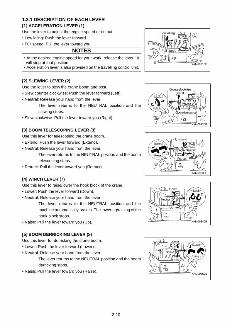
3-10
1.3.1 DESCRIPTION OF EACH LEVER [1] ACCELERATION LEVER (1)
Use the lever to adjust the engine speed or output.
• Low idling: Push the lever forward.
• Full speed: Pull the lever toward you.
NOTES
• At the desired engine speed for your work, release the lever. It will stop at that position.
• Acceleration lever is also provided on the travelling control unit.
[2] SLEWING LEVER (2)
Use the lever to slew the crane boom and post.
• Slew counter clockwise: Push the lever forward (Left).
• Neutral: Release your hand from the lever.
The lever returns to the NEUTRAL position and the
slewing stops.
• Slew clockwise: Pull the lever toward you (Right).
[3] BOOM TELESCOPING LEVER (3)
Use this lever for telescoping the crane boom.
• Extend: Push the lever forward (Extend).
• Neutral: Release your hand from the lever.
The lever returns to the NEUTRAL position and the boom
telescoping stops.
• Retract: Pull the lever toward you (Retract).
[4] WINCH LEVER (7)
Use this lever to raise/lower the hook block of the crane.
• Lower: Push the lever forward (Down).
• Neutral: Release your hand from the lever.
The lever returns to the NEUTRAL position and the
machine automatically brakes. The lowering/raising of the
hook block stops.
• Raise: Pull the lever toward you (Up).
[5] BOOM DERRICKING LEVER (8)
Use this lever for derricking the crane boom.
• Lower: Push the lever forward (Lower).
• Neutral: Release your hand from the lever.
The lever returns to the NEUTRAL position and the boom
derricking stops.
• Raise: Pull the lever toward you (Raise).
Lower
Hoist
Lower
Hoist
Neutral
XAM09850E
8
Down
Up
Down
Up
Neutral
XAM09840E
7
Extend
Retract
XAM09830E
Extend
Retract
Neutral
3
Left
Right
XAM09820E
Counterclockwiseswing
Clockwise swing
Neutral
2
XAM09810E
Full speed
Low idling1
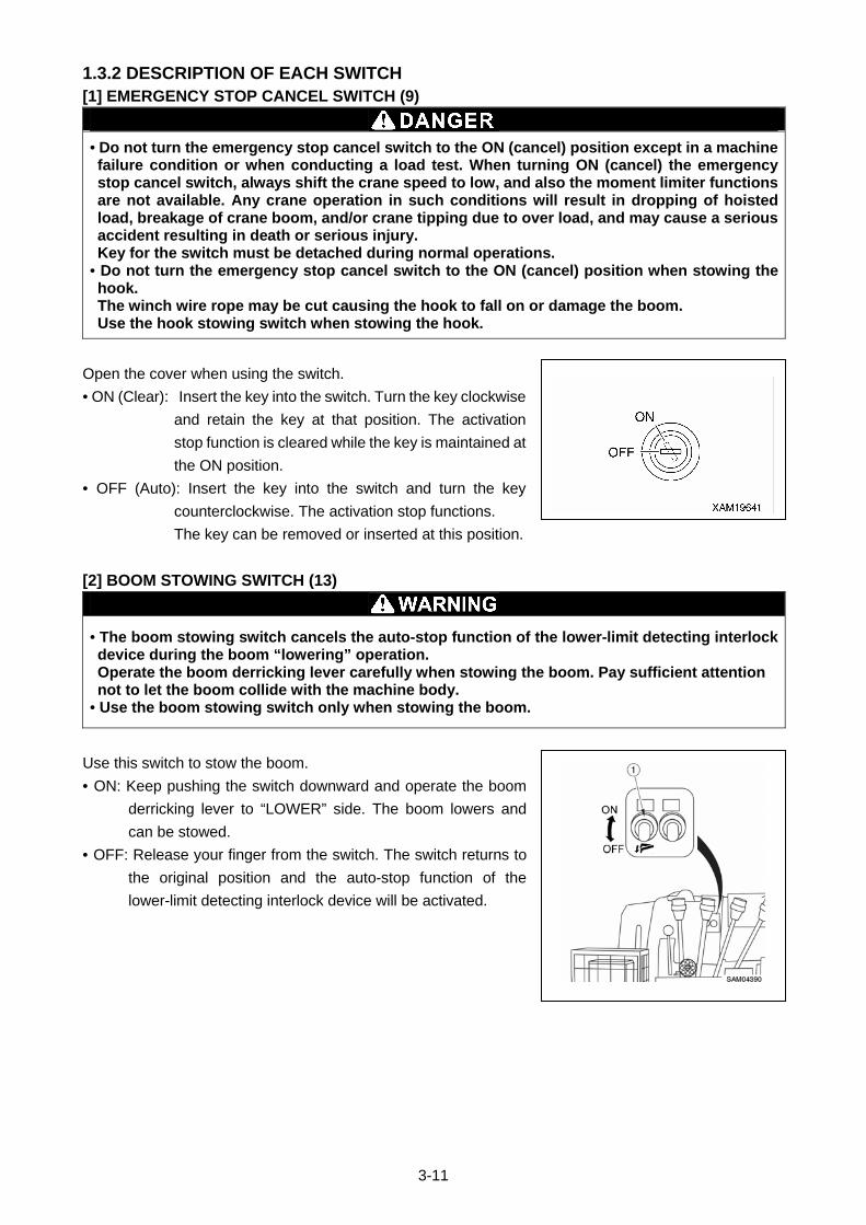
3-11
1.3.2 DESCRIPTION OF EACH SWITCH [1] EMERGENCY STOP CANCEL SWITCH (9)
• Do not turn the emergency stop cancel switch to the ON (cancel) position except in a machine failure condition or when conducting a load test. When turning ON (cancel) the emergency stop cancel switch, always shift the crane speed to low, and also the moment limiter functions are not available. Any crane operation in such conditions will result in dropping of hoisted load, breakage of crane boom, and/or crane tipping due to over load, and may cause a serious accident resulting in death or serious injury. Key for the switch must be detached during normal operations.
• Do not turn the emergency stop cancel switch to the ON (cancel) position when stowing the hook. The winch wire rope may be cut causing the hook to fall on or damage the boom. Use the hook stowing switch when stowing the hook.
Open the cover when using the switch.
• ON (Clear): Insert the key into the switch. Turn the key clockwise
and retain the key at that position. The activation
stop function is cleared while the key is maintained at
the ON position.
• OFF (Auto): Insert the key into the switch and turn the key
counterclockwise. The activation stop functions.
The key can be removed or inserted at this position.
[2] BOOM STOWING SWITCH (13)
• The boom stowing switch cancels the auto-stop function of the lower-limit detecting interlock device during the boom “lowering” operation. Operate the boom derricking lever carefully when stowing the boom. Pay sufficient attention not to let the boom collide with the machine body.
• Use the boom stowing switch only when stowing the boom.
Use this switch to stow the boom.
• ON: Keep pushing the switch downward and operate the boom
derricking lever to “LOWER” side. The boom lowers and
can be stowed.
• OFF: Release your finger from the switch. The switch returns to
the original position and the auto-stop function of the
lower-limit detecting interlock device will be activated.
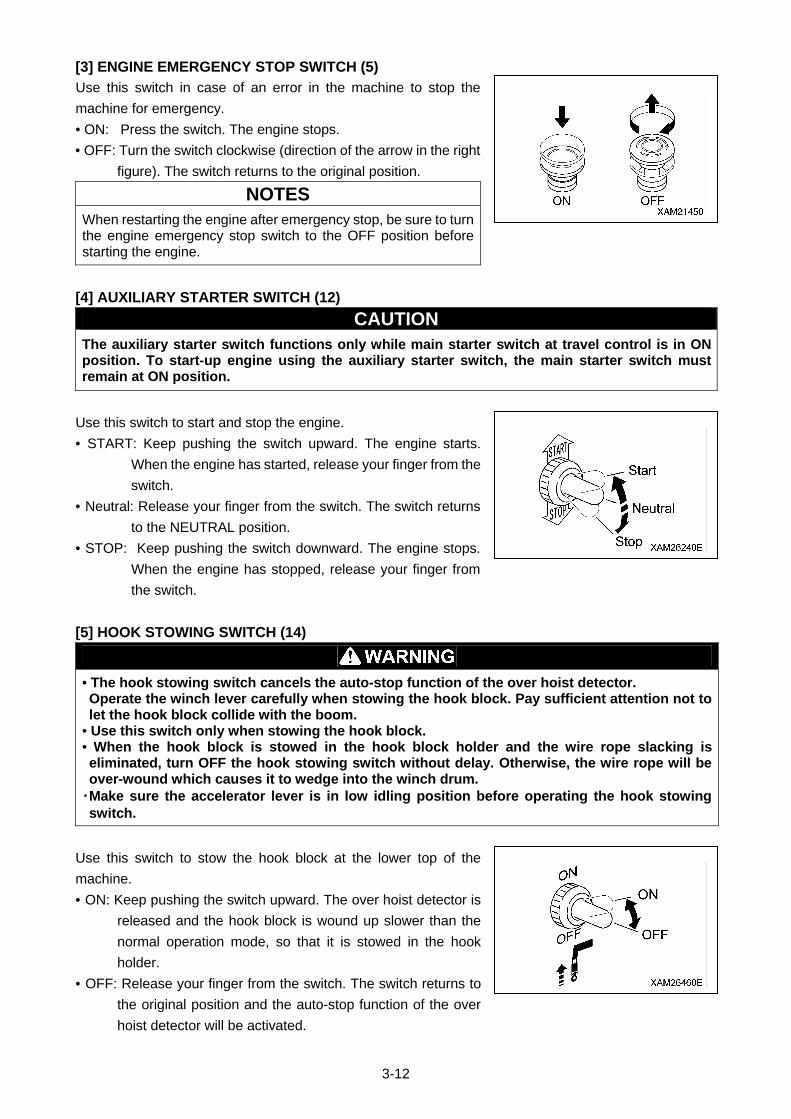
3-12
[3] ENGINE EMERGENCY STOP SWITCH (5)
Use this switch in case of an error in the machine to stop the
machine for emergency.
• ON: Press the switch. The engine stops.
• OFF: Turn the switch clockwise (direction of the arrow in the right
figure). The switch returns to the original position.
NOTES
When restarting the engine after emergency stop, be sure to turn the engine emergency stop switch to the OFF position before starting the engine.
[4] AUXILIARY STARTER SWITCH (12)
CAUTION The auxiliary starter switch functions only while main starter switch at travel control is in ON position. To start-up engine using the auxiliary starter switch, the main starter switch must remain at ON position.
Use this switch to start and stop the engine.
• START: Keep pushing the switch upward. The engine starts.
When the engine has started, release your finger from the
switch.
• Neutral: Release your finger from the switch. The switch returns
to the NEUTRAL position.
• STOP: Keep pushing the switch downward. The engine stops.
When the engine has stopped, release your finger from
the switch.
[5] HOOK STOWING SWITCH (14)
• The hook stowing switch cancels the auto-stop function of the over hoist detector. Operate the winch lever carefully when stowing the hook block. Pay sufficient attention not to let the hook block collide with the boom.
• Use this switch only when stowing the hook block. • When the hook block is stowed in the hook block holder and the wire rope slacking is eliminated, turn OFF the hook stowing switch without delay. Otherwise, the wire rope will be over-wound which causes it to wedge into the winch drum.
・Make sure the accelerator lever is in low idling position before operating the hook stowing switch.
Use this switch to stow the hook block at the lower top of the
machine.
• ON: Keep pushing the switch upward. The over hoist detector is
released and the hook block is wound up slower than the
normal operation mode, so that it is stowed in the hook
holder.
• OFF: Release your finger from the switch. The switch returns to
the original position and the auto-stop function of the over
hoist detector will be activated.
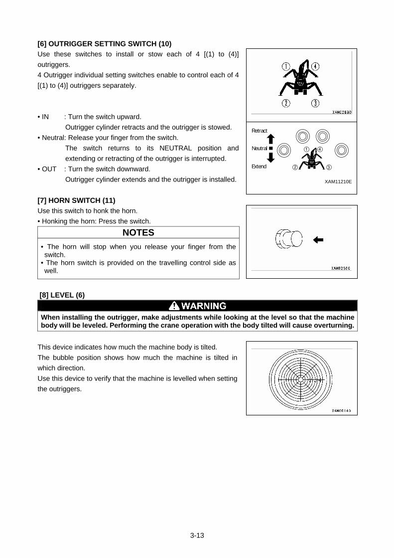
3-13
[6] OUTRIGGER SETTING SWITCH (10)
Use these switches to install or stow each of 4 [(1) to (4)]
outriggers.
4 Outrigger individual setting switches enable to control each of 4
[(1) to (4)] outriggers separately.
• IN : Turn the switch upward.
Outrigger cylinder retracts and the outrigger is stowed.
• Neutral: Release your finger from the switch.
The switch returns to its NEUTRAL position and
extending or retracting of the outrigger is interrupted.
• OUT : Turn the switch downward.
Outrigger cylinder extends and the outrigger is installed.
[7] HORN SWITCH (11)
Use this switch to honk the horn.
• Honking the horn: Press the switch.
NOTES
• The horn will stop when you release your finger from the switch.
• The horn switch is provided on the travelling control side as well.
[8] LEVEL (6)
When installing the outrigger, make adjustments while looking at the level so that the machine body will be leveled. Performing the crane operation with the body tilted will cause overturning.
This device indicates how much the machine body is tilted.
The bubble position shows how much the machine is tilted in
which direction.
Use this device to verify that the machine is levelled when setting
the outriggers.
XAM11210E
Neutral
Retract
Extend

3-14
1.4 OUTRIGGER SAFETY DEVICES
1.4.1 FUNCTIONS OF OUTRIGGER SAFETY DEVICES The outrigger safety devices have the interlock functions shown in the table below.
Interlock Function
Description of Interlock Function
1 Outrigger Interlock
Outriggers are not enable unless outrigger rotary is set to outward where position pin holes are aligned and ready for pin insertion with boom being stowed (boom lowered to maximum, slewed and stored).. • Whether the boom is lowered to the maximum is verified by the detection switch located to the post.
• Install a protrusion on the post at the boom slew and stow position and a detector switch on the travelling dolly in order to detect whether the boom has stopped at the slew and stow position.
2 Crane Interlock
The crane operation (telescoping, raising/lowering hook, derricking, and slewing) is enabled only when all four outriggers are extended and set (overhung and grounded). The outrigger extension status is detected as follows. •Install a detection switch at outrigger rotary section to detect proper positioning of rotary for setting outriggers.
• Install a detection switch inside the outrigger inner box to detect if the tray is seated properly through the detection pin installed between the tip of the inner box and the tray.
CAUTION
• Set the outriggers in the extension status and operate the work selector switch in the outrigger operation panel to the “CRANE” position to enable the crane operation. When the detection condition for setting one of the four outriggers (see the item 2 in the table above) is no more fulfilled, the working status lamp (red) rotates and lights up, and outrigger un-set warning lamp (red) flashes. If this state remains for 3 seconds or more, the crane interlock function is activated and the crane operation will be disabled.
• Stow the crane and operate the work selector switch on the outrigger operation panel to the “OUTRIGGER” position to enable the outrigger setting and extension operations.
• If the crane operation is not enabled after operating the work selector switch on the outrigger operation panel to the “CRANE” position even after the outrigger is being extended and set, there may be faulty adjustment or failure in the outrigger safety device. Please ask us or our sales service agency for repair.
• After rotating outriggers to outward, properly insert position pins for locking.
3-15
1.4.2 NAMES AND DESCRIPTIONS OF OUTRIGGER DISPLAY
(1) Outrigger setting lamp
(2) Outrigger angle setting lamp
(3) Boom stowing lamp
• Do not remove, disassemble, or repair detection switches. Do not move the detection switches from the original location to another.
• If you hit detection switches or find damage to the detection switches, be sure to check the ON/OFF operation of the lamps on the outrigger display and operation of the crane interlock function and outrigger interlock function. If you find any error, ask us or our sales service agency for repair.
[1] OUTRIGGER SETTING LAMPS (LED, CHANGES TO GREEN/RED)
This LED indicates that the outriggers are set by its illumination.
The LED lights up in green when the outrigger tray is set and the
LED blinks on and off in red when the tray floats (stow).
The conditions of the outrigger trays are detected by the base of the Outrigger cylinder.
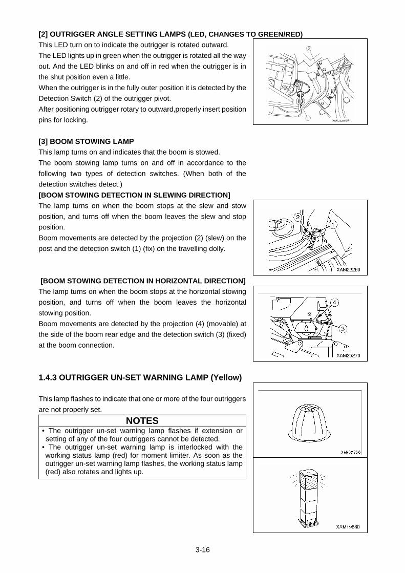
3-16
[2] OUTRIGGER ANGLE SETTING LAMPS (LED, CHANGES TO GREEN/RED)
This LED turn on to indicate the outrigger is rotated outward.
The LED lights up in green when the outrigger is rotated all the way
out. And the LED blinks on and off in red when the outrigger is in
the shut position even a little.
When the outrigger is in the fully outer position it is detected by the
Detection Switch (2) of the outrigger pivot.
After positioning outrigger rotary to outward,properly insert position
pins for locking.
[3] BOOM STOWING LAMP
This lamp turns on and indicates that the boom is stowed.
The boom stowing lamp turns on and off in accordance to the
following two types of detection switches. (When both of the
detection switches detect.)
[BOOM STOWING DETECTION IN SLEWING DIRECTION]
The lamp turns on when the boom stops at the slew and stow
position, and turns off when the boom leaves the slew and stop
position.
Boom movements are detected by the projection (2) (slew) on the
post and the detection switch (1) (fix) on the travelling dolly.
[BOOM STOWING DETECTION IN HORIZONTAL DIRECTION]
The lamp turns on when the boom stops at the horizontal stowing
position, and turns off when the boom leaves the horizontal
stowing position.
Boom movements are detected by the projection (4) (movable) at
the side of the boom rear edge and the detection switch (3) (fixed)
at the boom connection.
1.4.3 OUTRIGGER UN-SET WARNING LAMP (Yellow)
This lamp flashes to indicate that one or more of the four outriggers
are not properly set.
NOTES • The outrigger un-set warning lamp flashes if extension or setting of any of the four outriggers cannot be detected.
• The outrigger un-set warning lamp is interlocked with the working status lamp (red) for moment limiter. As soon as the outrigger un-set warning lamp flashes, the working status lamp (red) also rotates and lights up.
3-17
1.5 MOMENT LIMITER (OVERLOAD DETECTOR)
1.5.1 MOMENT LIMITER CONFIGURATION
(1) Moment limiter display unit
(2) Emergency stop cancel switch
(3) Moment limiter converter
(4) Working status lamp
(A) Red working status lamp (Warning lamp for
load factor of 100 % or more)
(B) Yellow working status lamp (Pre-warning
lamp for load factor of 90 to 100 %)
(C) Green working status lamp (Working lamp
for load factor of less than 90 %)
(5) Boom length gauge (inside boom)
(6) Boom angle gauge (side of boom rear edge)
(7) Pressure sensor (derrick cylinder) (two)
(8) Over hoist detector (side of boom tip)
(9) Outrigger position detection switch
XAM23301E-R1
8
7
2
9
9
3
9
4
1
ABC
65
3-18
1.5.2 FUNCTION OF MOMENT LIMITER
• Do not remove, disassemble, or repair detectors. Do not move the detectors to another location from original position.
• Should an object hit a detector or you find any damage on a detector, be sure to verify the actuation status of the auto stop. If you find any abnormality with the actuation of the auto stop, do not fail to fix it.
• Do not turn ON (cancel) the emergency stop cancel switch unless you find an error or check/perform maintenance on detectors. When turning ON (cancel) the emergency stop cancel switch, always shift the crane speed to low. Overloading can cause the hoisted load to fall, boom breakage, or overturning of this machine that can lead to serious accidents resulting in death or serious injury.
• The machine will not stop automatically even if the crane is overloaded during the crane slewing operation. Do not slew the crane when being overloaded.
• When the boom approaches the stop position during the operation, be sure to change the operation speed of the boom to low speed. With high-speed boom operation, the boom may overrun the specified stop position, causing serious accidents such as overturning of the machine resulting in death or serious injury.
The moment limiter is a device installed to prevent the hoisted load from falling, the boom from breaking,
or the machine from overturning due to overloading.
Always check the operation of the moment limiter before crane operation to verify no abnormality.
[1] MECHANISM OF MOMENT LIMITER
The moment limiter calculates current "rated total load" by knowing
the current boom posture by the boom angle gauge and the boom
length gauge, by knowing the outrigger extension condition by the
outrigger position switch, and by knowing the number of wire falls
(entered by the driver).
Then by actually hoisting a load, the "read load" (hoist load) is sent
from the pressure sensor of the derrick cylinder to the moment
limiter.
The moment limiter comparatively calculates between the "rated
total load" computed out of the current posture and the "real load"
(hoisted load), and issues alarm if the result indicates the real
load/rated total load=90 to 100%.
If the calculation result indicates the real load/rated total
load=above 100%, an alarm is issued and the causes the boom
operation to automatically stop.
[2] DISPLAY OF THE MOMENT LIMITER ERROR MESSAGES
The moment limiter performs self-diagnosis on the moment limiter display unit when an error is issued by
the boom angle gauge, boom length gauge, pressure sensor, or when a circuit is opened or a connector is
disconnected.
The result is displayed on the “Rated total load Display” of the moment limiter display unit by an error code
to notify the operator of the error.
Immediately stop the use of the crane when an error code is displayed.
See “Operation 1.5.9 Moment Limiter Error Causes and Actions to be taken”.
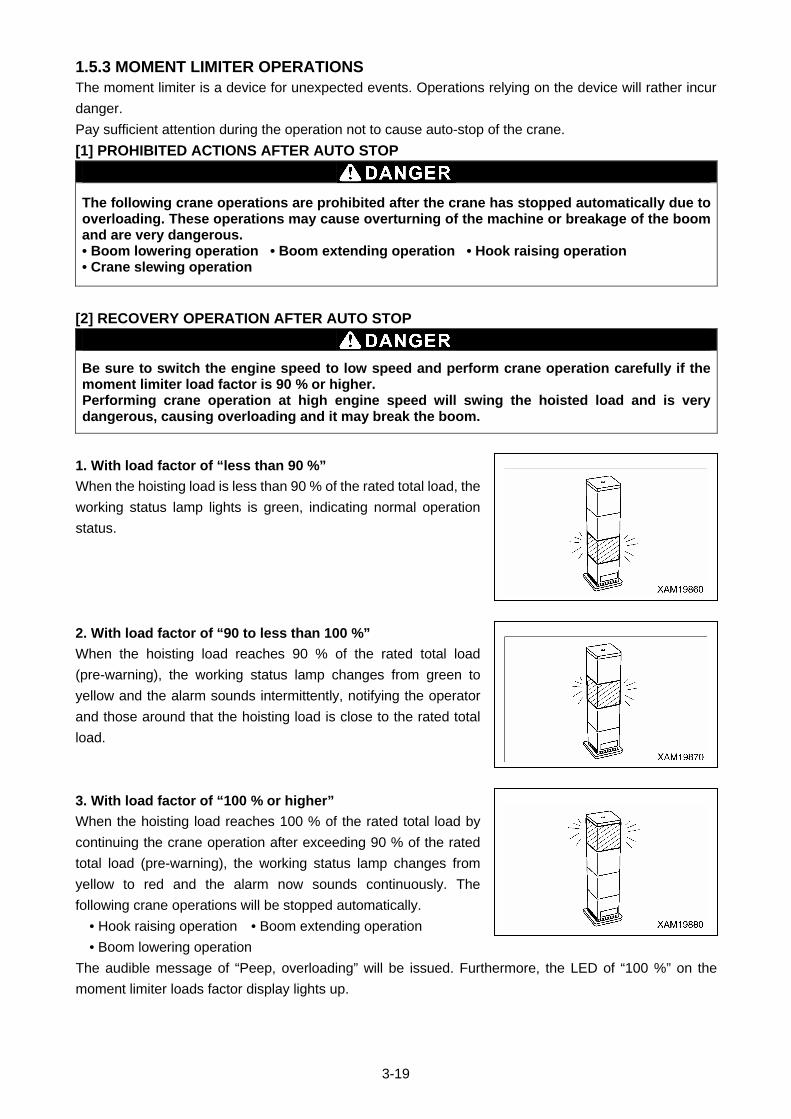
3-19
1.5.3 MOMENT LIMITER OPERATIONS The moment limiter is a device for unexpected events. Operations relying on the device will rather incur
danger.
Pay sufficient attention during the operation not to cause auto-stop of the crane.
[1] PROHIBITED ACTIONS AFTER AUTO STOP
The following crane operations are prohibited after the crane has stopped automatically due to overloading. These operations may cause overturning of the machine or breakage of the boom and are very dangerous. • Boom lowering operation • Boom extending operation • Hook raising operation • Crane slewing operation
[2] RECOVERY OPERATION AFTER AUTO STOP
Be sure to switch the engine speed to low speed and perform crane operation carefully if the moment limiter load factor is 90 % or higher. Performing crane operation at high engine speed will swing the hoisted load and is very dangerous, causing overloading and it may break the boom.
1. With load factor of “less than 90 %”
When the hoisting load is less than 90 % of the rated total load, the
working status lamp lights is green, indicating normal operation
status.
2. With load factor of “90 to less than 100 %”
When the hoisting load reaches 90 % of the rated total load
(pre-warning), the working status lamp changes from green to
yellow and the alarm sounds intermittently, notifying the operator
and those around that the hoisting load is close to the rated total
load.
3. With load factor of “100 % or higher”
When the hoisting load reaches 100 % of the rated total load by
continuing the crane operation after exceeding 90 % of the rated
total load (pre-warning), the working status lamp changes from
yellow to red and the alarm now sounds continuously. The
following crane operations will be stopped automatically.
• Hook raising operation • Boom extending operation
• Boom lowering operation
The audible message of “Peep, overloading” will be issued. Furthermore, the LED of “100 %” on the
moment limiter loads factor display lights up.
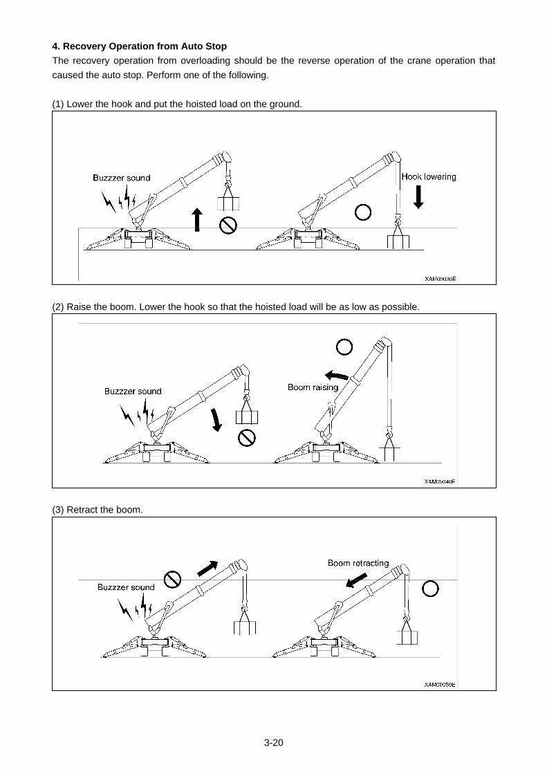
3-20
4. Recovery Operation from Auto Stop
The recovery operation from overloading should be the reverse operation of the crane operation that
caused the auto stop. Perform one of the following.
(1) Lower the hook and put the hoisted load on the ground.
(2) Raise the boom. Lower the hook so that the hoisted load will be as low as possible.
(3) Retract the boom.

3-21
1.5.4 NAMES OF MOMENT LIMITER DISPLAY UNIT
(1) Boom angle display
(2) Lifting height display
(3) Boom length display
(4) Boom lifting height upper limit LED
(Orange)
(5) Boom lifting height upper limit switch
(6) Boom angle lower limit LED (Orange)
(7) Boom angle lower limit switch
(8) Load factor LED
(Changes to green, yellow, and red)
(9) Over hoist detection LED (Red)
(10) Load capacity display (Yellow)
(11) Actual load display
(12) Rated total load display
(13) Working radius display
(14) Working radius upper limit switch
(15) Working radius upper limit LED (Orange)
(16) Over un-winding LED (Red)
(17) Boom angle upper limit switch
(18) Boom angle upper limit LED (Orange)
(19) Outrigger MIN. extension LED (Blue)
(20) Outrigger MAX. extension LED (Blue)
(21) Check switch
(22) Cancel switch
(23) Fall mode selector switch
(24) 1-fall fall LED (Blue)
(25) 2-falls fall LED (Blue)
(26) 4-falls fall LED (Blue)
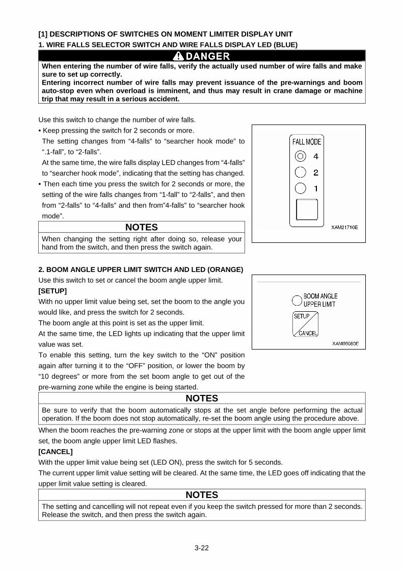
3-22
[1] DESCRIPTIONS OF SWITCHES ON MOMENT LIMITER DISPLAY UNIT
1. WIRE FALLS SELECTOR SWITCH AND WIRE FALLS DISPLAY LED (BLUE)
When entering the number of wire falls, verify the actually used number of wire falls and make sure to set up correctly. Entering incorrect number of wire falls may prevent issuance of the pre-warnings and boom auto-stop even when overload is imminent, and thus may result in crane damage or machine trip that may result in a serious accident.
Use this switch to change the number of wire falls.
• Keep pressing the switch for 2 seconds or more.
The setting changes from “4-falls” to “searcher hook mode” to
“.1-fall”, to “2-falls”.
At the same time, the wire falls display LED changes from “4-falls”
to “searcher hook mode”, indicating that the setting has changed.
• Then each time you press the switch for 2 seconds or more, the
setting of the wire falls changes from “1-fall” to “2-falls”, and then
from “2-falls” to “4-falls” and then from”4-falls” to “searcher hook
mode”.
NOTES
When changing the setting right after doing so, release your hand from the switch, and then press the switch again.
2. BOOM ANGLE UPPER LIMIT SWITCH AND LED (ORANGE)
Use this switch to set or cancel the boom angle upper limit.
[SETUP]
With no upper limit value being set, set the boom to the angle you
would like, and press the switch for 2 seconds.
The boom angle at this point is set as the upper limit.
At the same time, the LED lights up indicating that the upper limit
value was set.
To enable this setting, turn the key switch to the “ON” position
again after turning it to the “OFF” position, or lower the boom by
“10 degrees” or more from the set boom angle to get out of the
pre-warning zone while the engine is being started.
NOTES
Be sure to verify that the boom automatically stops at the set angle before performing the actual operation. If the boom does not stop automatically, re-set the boom angle using the procedure above.
When the boom reaches the pre-warning zone or stops at the upper limit with the boom angle upper limit
set, the boom angle upper limit LED flashes.
[CANCEL]
With the upper limit value being set (LED ON), press the switch for 5 seconds.
The current upper limit value setting will be cleared. At the same time, the LED goes off indicating that the
upper limit value setting is cleared.
NOTES
The setting and cancelling will not repeat even if you keep the switch pressed for more than 2 seconds. Release the switch, and then press the switch again.
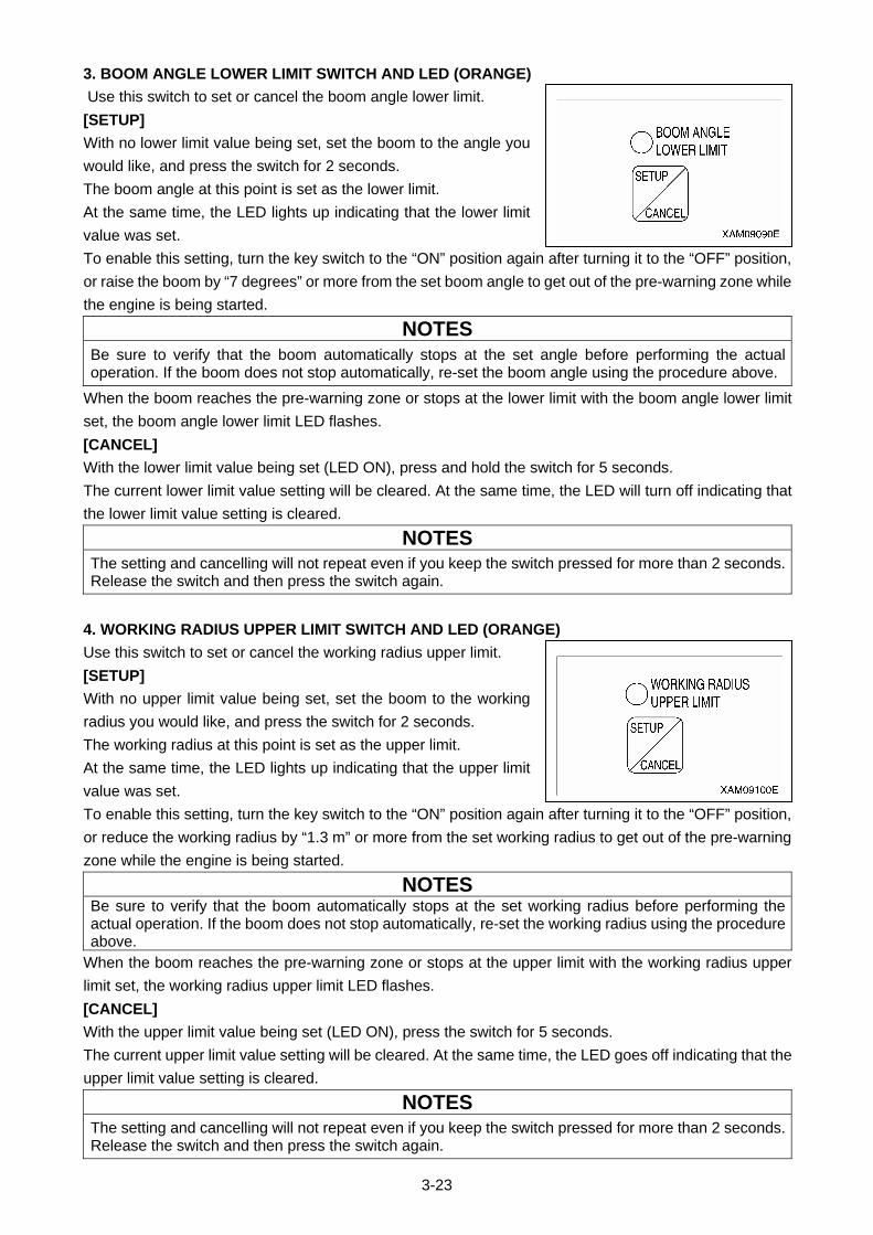
3-23
3. BOOM ANGLE LOWER LIMIT SWITCH AND LED (ORANGE)
Use this switch to set or cancel the boom angle lower limit.
[SETUP]
With no lower limit value being set, set the boom to the angle you
would like, and press the switch for 2 seconds.
The boom angle at this point is set as the lower limit.
At the same time, the LED lights up indicating that the lower limit
value was set.
To enable this setting, turn the key switch to the “ON” position again after turning it to the “OFF” position,
or raise the boom by “7 degrees” or more from the set boom angle to get out of the pre-warning zone while
the engine is being started.
NOTES
Be sure to verify that the boom automatically stops at the set angle before performing the actual operation. If the boom does not stop automatically, re-set the boom angle using the procedure above.
When the boom reaches the pre-warning zone or stops at the lower limit with the boom angle lower limit
set, the boom angle lower limit LED flashes.
[CANCEL]
With the lower limit value being set (LED ON), press and hold the switch for 5 seconds.
The current lower limit value setting will be cleared. At the same time, the LED will turn off indicating that
the lower limit value setting is cleared.
NOTES
The setting and cancelling will not repeat even if you keep the switch pressed for more than 2 seconds. Release the switch and then press the switch again.
4. WORKING RADIUS UPPER LIMIT SWITCH AND LED (ORANGE)
Use this switch to set or cancel the working radius upper limit.
[SETUP]
With no upper limit value being set, set the boom to the working
radius you would like, and press the switch for 2 seconds.
The working radius at this point is set as the upper limit.
At the same time, the LED lights up indicating that the upper limit
value was set.
To enable this setting, turn the key switch to the “ON” position again after turning it to the “OFF” position,
or reduce the working radius by “1.3 m” or more from the set working radius to get out of the pre-warning
zone while the engine is being started.
NOTES Be sure to verify that the boom automatically stops at the set working radius before performing the actual operation. If the boom does not stop automatically, re-set the working radius using the procedure above.
When the boom reaches the pre-warning zone or stops at the upper limit with the working radius upper
limit set, the working radius upper limit LED flashes.
[CANCEL]
With the upper limit value being set (LED ON), press the switch for 5 seconds.
The current upper limit value setting will be cleared. At the same time, the LED goes off indicating that the
upper limit value setting is cleared.
NOTES
The setting and cancelling will not repeat even if you keep the switch pressed for more than 2 seconds. Release the switch and then press the switch again.
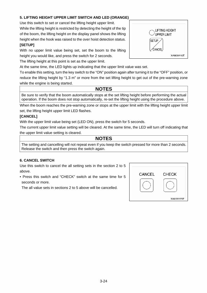
3-24
5. LIFTING HEIGHT UPPER LIMIT SWITCH AND LED (ORANGE)
Use this switch to set or cancel the lifting height upper limit.
While the lifting height is restricted by detecting the height of the tip
of the boom, the lifting height on the display panel shows the lifting
height when the hook was raised to the over hoist detection status.
[SETUP]
With no upper limit value being set, set the boom to the lifting
height you would like, and press the switch for 2 seconds.
The lifting height at this point is set as the upper limit.
At the same time, the LED lights up indicating that the upper limit value was set.
To enable this setting, turn the key switch to the “ON” position again after turning it to the “OFF” position, or
reduce the lifting height by “1.3 m” or more from the set lifting height to get out of the pre-warning zone
while the engine is being started.
NOTES
Be sure to verify that the boom automatically stops at the set lifting height before performing the actual operation. If the boom does not stop automatically, re-set the lifting height using the procedure above.
When the boom reaches the pre-warning zone or stops at the upper limit with the lifting height upper limit
set, the lifting height upper limit LED flashes.
[CANCEL]
With the upper limit value being set (LED ON), press the switch for 5 seconds.
The current upper limit value setting will be cleared. At the same time, the LED will turn off indicating that
the upper limit value setting is cleared.
NOTES
The setting and cancelling will not repeat even if you keep the switch pressed for more than 2 seconds. Release the switch and then press the switch again.
6. CANCEL SWITCH
Use this switch to cancel the all setting sets in the section 2 to 5
above.
• Press this switch and “CHECK” switch at the same time for 5
seconds or more.
The all value sets in sections 2 to 5 above will be cancelled.
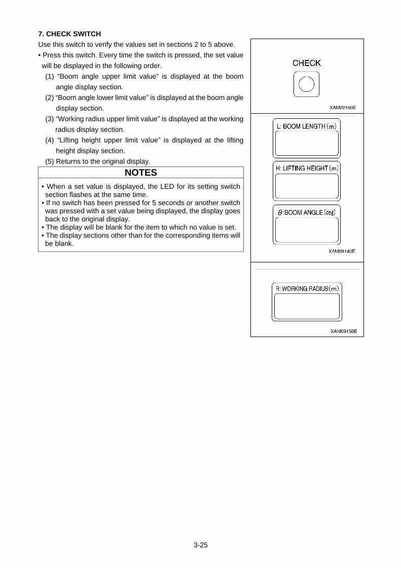
3-25
7. CHECK SWITCH
Use this switch to verify the values set in sections 2 to 5 above.
• Press this switch. Every time the switch is pressed, the set value
will be displayed in the following order.
(1) “Boom angle upper limit value” is displayed at the boom
angle display section.
(2) “Boom angle lower limit value” is displayed at the boom angle
display section.
(3) “Working radius upper limit value” is displayed at the working
radius display section.
(4) “Lifting height upper limit value” is displayed at the lifting
height display section.
(5) Returns to the original display.
NOTES
• When a set value is displayed, the LED for its setting switch section flashes at the same time.
• If no switch has been pressed for 5 seconds or another switch was pressed with a set value being displayed, the display goes back to the original display.
• The display will be blank for the item to which no value is set. • The display sections other than for the corresponding items will be blank.
3-26
[2] DESCRIPTIONS OF MOMENT LIMITER DISPLAY UNIT
For LEDs not described in this section, see “Operation 1.5.4 Names of moment limiter display unit”.
1. ACTUAL LOAD DISPLAY SECTION
This section constantly displays the actual load of the hoisted load
during the crane operation.
The actual load indicates the total weight of the hoisted load
including rigging and the hook block.
If “0.0” to “0.1” is displayed when nothing is being hoisted, the
system is normal.
If the value displayed is out of this range, contact us or our sales
service agency.
2. RATED TOTAL LOAD DISPLAY SECTION
This section displays the number of wire falls on the hook, working
radius, current hoistable rated total load (hook weight + rigging
weight + load to be hoisted) computed out of the conditions such
as the degree of outrigger extension.
3. WORKING RADIUS DISPLAY SECTION
This section constantly displays the current working radius during
the crane operation.
The working radius is the horizontal distance from the crane
slewing centre to the centre of the hook.
4. BOOM LENGTH DISPLAY SECTION
This section constantly displays the current boom length during the
crane operation.
The boom length is the distance from the boom foot pin to the
sheave pin at the end of the boom.
5. LIFTING HEIGHT DISPLAY SECTION
This section constantly displays the current lifting height during the
crane operation.
The lifting height is the vertical distance from the ground to the
bottom of the hook.
6. BOOM ANGLE DISPLAY SECTION
This section constantly displays the current boom angle during the
crane operation.
The boom angle is the angle formed between the boom and the
horizontal line.
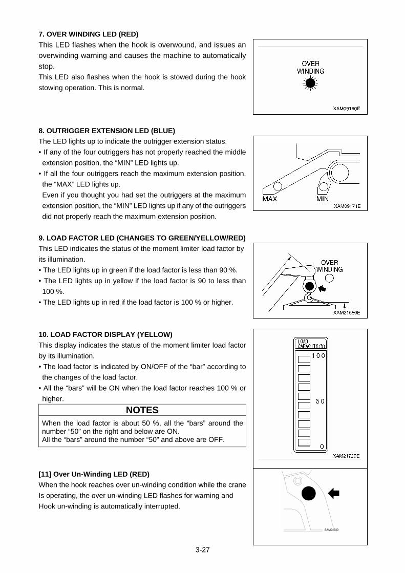
3-27
7. OVER WINDING LED (RED)
This LED flashes when the hook is overwound, and issues an
overwinding warning and causes the machine to automatically
stop.
This LED also flashes when the hook is stowed during the hook
stowing operation. This is normal.
8. OUTRIGGER EXTENSION LED (BLUE)
The LED lights up to indicate the outrigger extension status.
• If any of the four outriggers has not properly reached the middle
extension position, the “MIN” LED lights up.
• If all the four outriggers reach the maximum extension position,
the “MAX” LED lights up.
Even if you thought you had set the outriggers at the maximum
extension position, the “MIN” LED lights up if any of the outriggers
did not properly reach the maximum extension position.
9. LOAD FACTOR LED (CHANGES TO GREEN/YELLOW/RED)
This LED indicates the status of the moment limiter load factor by
its illumination.
• The LED lights up in green if the load factor is less than 90 %.
• The LED lights up in yellow if the load factor is 90 to less than
100 %.
• The LED lights up in red if the load factor is 100 % or higher.
10. LOAD FACTOR DISPLAY (YELLOW)
This display indicates the status of the moment limiter load factor
by its illumination.
• The load factor is indicated by ON/OFF of the “bar” according to
the changes of the load factor.
• All the “bars” will be ON when the load factor reaches 100 % or
higher.
NOTES
When the load factor is about 50 %, all the “bars” around the number “50” on the right and below are ON. All the “bars” around the number “50” and above are OFF.
[11] Over Un-Winding LED (RED)
When the hook reaches over un-winding condition while the crane
Is operating, the over un-winding LED flashes for warning and
Hook un-winding is automatically interrupted.
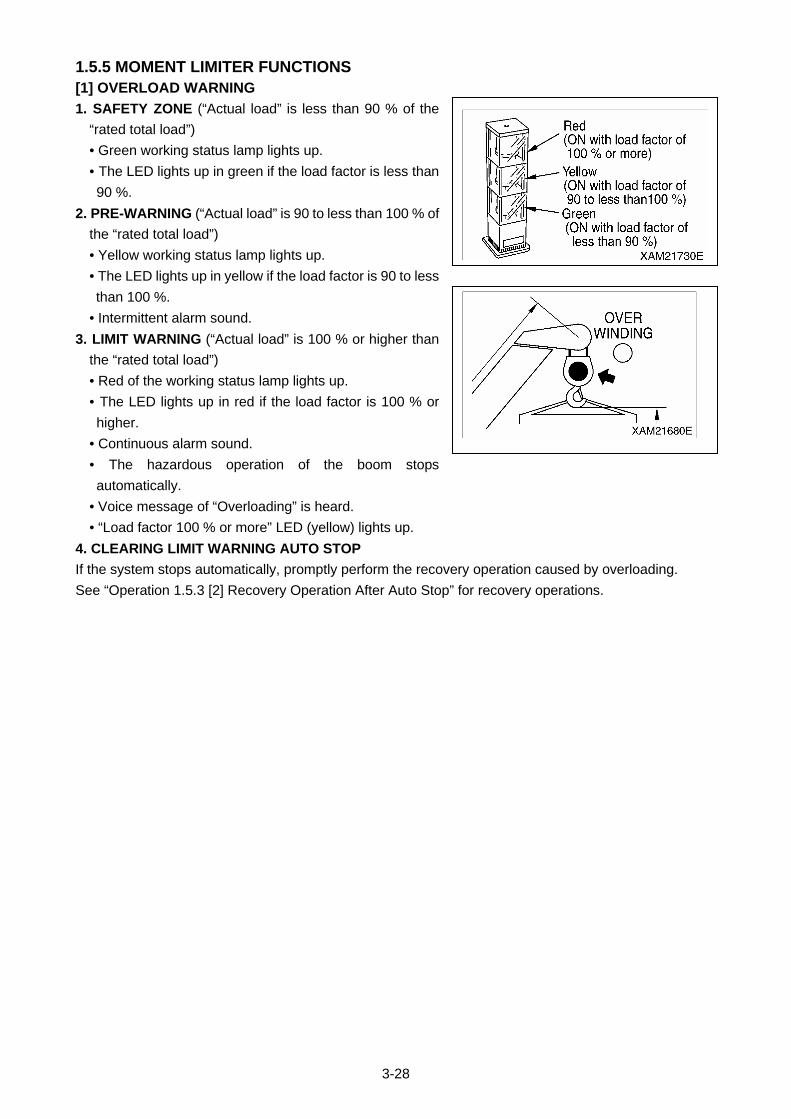
3-28
1.5.5 MOMENT LIMITER FUNCTIONS [1] OVERLOAD WARNING
1. SAFETY ZONE (“Actual load” is less than 90 % of the
“rated total load”)
• Green working status lamp lights up.
• The LED lights up in green if the load factor is less than
90 %.
2. PRE-WARNING (“Actual load” is 90 to less than 100 % of
the “rated total load”)
• Yellow working status lamp lights up.
• The LED lights up in yellow if the load factor is 90 to less
than 100 %.
• Intermittent alarm sound.
3. LIMIT WARNING (“Actual load” is 100 % or higher than
the “rated total load”)
• Red of the working status lamp lights up.
• The LED lights up in red if the load factor is 100 % or
higher.
• Continuous alarm sound.
• The hazardous operation of the boom stops
automatically.
• Voice message of “Overloading” is heard.
• “Load factor 100 % or more” LED (yellow) lights up.
4. CLEARING LIMIT WARNING AUTO STOP
If the system stops automatically, promptly perform the recovery operation caused by overloading.
See “Operation 1.5.3 [2] Recovery Operation After Auto Stop” for recovery operations.
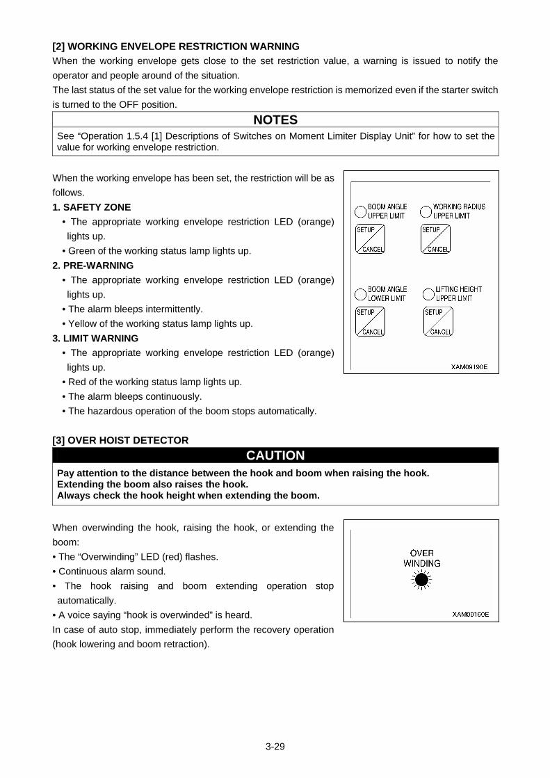
3-29
[2] WORKING ENVELOPE RESTRICTION WARNING
When the working envelope gets close to the set restriction value, a warning is issued to notify the
operator and people around of the situation.
The last status of the set value for the working envelope restriction is memorized even if the starter switch
is turned to the OFF position.
NOTES
See “Operation 1.5.4 [1] Descriptions of Switches on Moment Limiter Display Unit” for how to set the value for working envelope restriction.
When the working envelope has been set, the restriction will be as
follows.
1. SAFETY ZONE
• The appropriate working envelope restriction LED (orange)
lights up.
• Green of the working status lamp lights up.
2. PRE-WARNING
• The appropriate working envelope restriction LED (orange)
lights up.
• The alarm bleeps intermittently.
• Yellow of the working status lamp lights up.
3. LIMIT WARNING
• The appropriate working envelope restriction LED (orange)
lights up.
• Red of the working status lamp lights up.
• The alarm bleeps continuously.
• The hazardous operation of the boom stops automatically.
[3] OVER HOIST DETECTOR
CAUTION Pay attention to the distance between the hook and boom when raising the hook. Extending the boom also raises the hook. Always check the hook height when extending the boom.
When overwinding the hook, raising the hook, or extending the
boom:
• The “Overwinding” LED (red) flashes.
• Continuous alarm sound.
• The hook raising and boom extending operation stop
automatically.
• A voice saying “hook is overwinded” is heard.
In case of auto stop, immediately perform the recovery operation
(hook lowering and boom retraction).
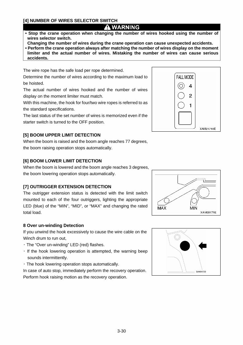
3-30
[4] NUMBER OF WIRES SELECTOR SWITCH
• Stop the crane operation when changing the number of wires hooked using the number of wires selector switch. Changing the number of wires during the crane operation can cause unexpected accidents.
• Perform the crane operation always after matching the number of wires display on the moment limiter and the actual number of wires. Mistaking the number of wires can cause serious accidents.
The wire rope has the safe load per rope determined.
Determine the number of wires according to the maximum load to
be hoisted.
The actual number of wires hooked and the number of wires
display on the moment limiter must match.
With this machine, the hook for four/two wire ropes is referred to as
the standard specifications.
The last status of the set number of wires is memorized even if the
starter switch is turned to the OFF position.
[5] BOOM UPPER LIMIT DETECTION
When the boom is raised and the boom angle reaches 77 degrees,
the boom raising operation stops automatically.
[6] BOOM LOWER LIMIT DETECTION
When the boom is lowered and the boom angle reaches 3 degrees,
the boom lowering operation stops automatically.
[7] OUTRIGGER EXTENSION DETECTION
The outrigger extension status is detected with the limit switch
mounted to each of the four outriggers, lighting the appropriate
LED (blue) of the “MIN”, “MID”, or “MAX” and changing the rated
total load.
8 Over un-winding Detection
If you unwind the hook excessively to cause the wire cable on the
Winch drum to run out,
・ The “Over un-winding” LED (red) flashes.
・ If the hook lowering operation is attempted, the warning beep
sounds intermittently.
・ The hook lowering operation stops automatically.
In case of auto stop, immediately perform the recovery operation.
Perform hook raising motion as the recovery operation.
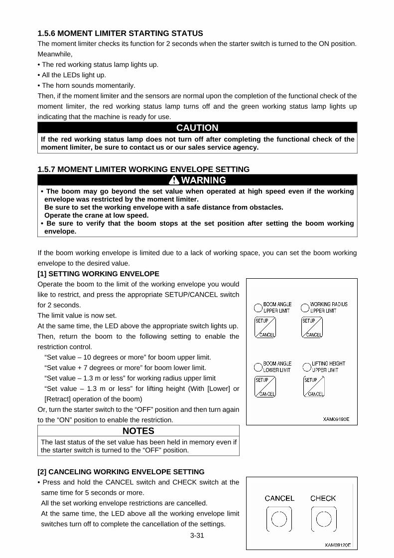
3-31
1.5.6 MOMENT LIMITER STARTING STATUS The moment limiter checks its function for 2 seconds when the starter switch is turned to the ON position.
Meanwhile,
• The red working status lamp lights up.
• All the LEDs light up.
• The horn sounds momentarily.
Then, if the moment limiter and the sensors are normal upon the completion of the functional check of the
moment limiter, the red working status lamp turns off and the green working status lamp lights up
indicating that the machine is ready for use.
CAUTION If the red working status lamp does not turn off after completing the functional check of the moment limiter, be sure to contact us or our sales service agency.
1.5.7 MOMENT LIMITER WORKING ENVELOPE SETTING
• The boom may go beyond the set value when operated at high speed even if the working envelope was restricted by the moment limiter. Be sure to set the working envelope with a safe distance from obstacles. Operate the crane at low speed.
• Be sure to verify that the boom stops at the set position after setting the boom working envelope.
If the boom working envelope is limited due to a lack of working space, you can set the boom working
envelope to the desired value.
[1] SETTING WORKING ENVELOPE
Operate the boom to the limit of the working envelope you would
like to restrict, and press the appropriate SETUP/CANCEL switch
for 2 seconds.
The limit value is now set.
At the same time, the LED above the appropriate switch lights up.
Then, return the boom to the following setting to enable the
restriction control.
“Set value – 10 degrees or more” for boom upper limit.
“Set value + 7 degrees or more” for boom lower limit.
“Set value – 1.3 m or less” for working radius upper limit
“Set value – 1.3 m or less” for lifting height (With [Lower] or
[Retract] operation of the boom)
Or, turn the starter switch to the “OFF” position and then turn again
to the “ON” position to enable the restriction.
NOTES
The last status of the set value has been held in memory even if the starter switch is turned to the “OFF” position.
[2] CANCELING WORKING ENVELOPE SETTING
• Press and hold the CANCEL switch and CHECK switch at the
same time for 5 seconds or more.
All the set working envelope restrictions are cancelled.
At the same time, the LED above all the working envelope limit
switches turn off to complete the cancellation of the settings.
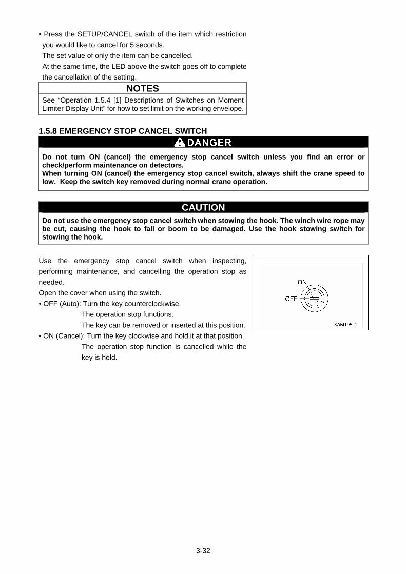
3-32
• Press the SETUP/CANCEL switch of the item which restriction
you would like to cancel for 5 seconds.
The set value of only the item can be cancelled.
At the same time, the LED above the switch goes off to complete
the cancellation of the setting.
NOTES
See “Operation 1.5.4 [1] Descriptions of Switches on Moment Limiter Display Unit” for how to set limit on the working envelope.
1.5.8 EMERGENCY STOP CANCEL SWITCH
Do not turn ON (cancel) the emergency stop cancel switch unless you find an error or check/perform maintenance on detectors. When turning ON (cancel) the emergency stop cancel switch, always shift the crane speed to low. Keep the switch key removed during normal crane operation.
CAUTION Do not use the emergency stop cancel switch when stowing the hook. The winch wire rope may be cut, causing the hook to fall or boom to be damaged. Use the hook stowing switch for stowing the hook.
Use the emergency stop cancel switch when inspecting,
performing maintenance, and cancelling the operation stop as
needed.
Open the cover when using the switch.
• OFF (Auto): Turn the key counterclockwise.
The operation stop functions.
The key can be removed or inserted at this position.
• ON (Cancel): Turn the key clockwise and hold it at that position.
The operation stop function is cancelled while the
key is held.

3-33
1.5.9 MOMENT LIMITER ERROR CAUSES AND ACTIONS TO BE TAKEN The moment limiter displays an error code at the “rated total load” display section on the display panel to
notify the error.
If an error code shown in the table below was displayed, contact us or our sales service agency.
Error Code Error Details Actions to Be Taken E1L
The input to pressure sensor 1 is lower than the specified value.
E1H
The input to pressure sensor 1 is higher than the specified value.
Check the installation of the pressure sensor 1.
E2L
The input to pressure sensor 2 is lower than the specified value.
E2H
The input to pressure sensor 2 is higher than the specified value.
Check the installation of the pressure sensor 2.
E3L
The input to angle detector is lower than the specified value.
E3H
The input to angle detector is higher than the specified value.
Check the installation of the angle detector.
E4L
The input to length detector is lower than the specified value.
E4H
The input to length detector is higher than the specified value.
Check the installation of the length detector.
EAD
The AD converter at the converter section is not functioning properly.
Turn the starter switch to the “OFF” position and then to the “ON” position again. If an error is displayed again, change the converter.
ERS
The communication between the converter section and the display unit is not carried out properly.
• Check the cable between the display unit and the converter. If the cable is normal, change the converter.
• Check the fuse built-in the converter.
E-E
Error with calibration memory. This error is also issued when calibration has not been done yet.
Turn the starter switch to the “OFF” position and then to the “ON” position again. If an error is displayed again, change the display unit.
No display --- Check the fuse built-in the display unit.
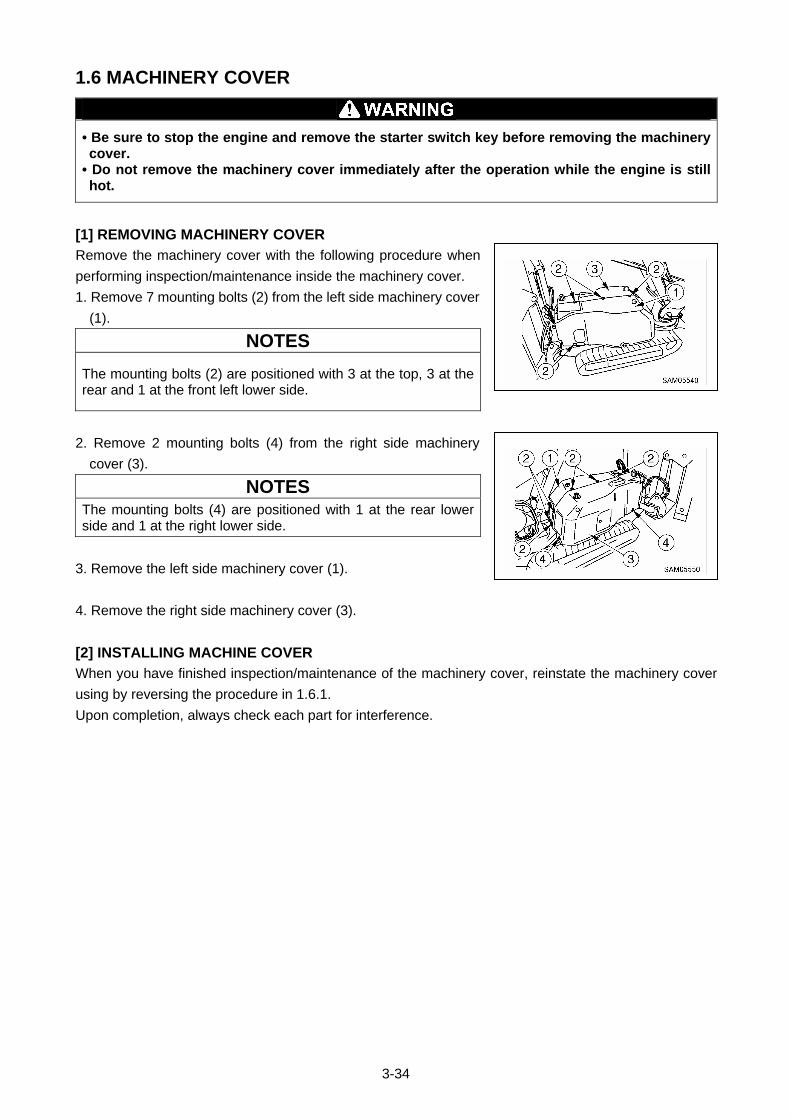
3-34
1.6 MACHINERY COVER
• Be sure to stop the engine and remove the starter switch key before removing the machinery cover.
• Do not remove the machinery cover immediately after the operation while the engine is still hot.
[1] REMOVING MACHINERY COVER
Remove the machinery cover with the following procedure when
performing inspection/maintenance inside the machinery cover.
1. Remove 7 mounting bolts (2) from the left side machinery cover
(1).
NOTES
The mounting bolts (2) are positioned with 3 at the top, 3 at the rear and 1 at the front left lower side.
2. Remove 2 mounting bolts (4) from the right side machinery
cover (3).
NOTES
The mounting bolts (4) are positioned with 1 at the rear lower side and 1 at the right lower side.
3. Remove the left side machinery cover (1).
4. Remove the right side machinery cover (3).
[2] INSTALLING MACHINE COVER
When you have finished inspection/maintenance of the machinery cover, reinstate the machinery cover
using by reversing the procedure in 1.6.1.
Upon completion, always check each part for interference.
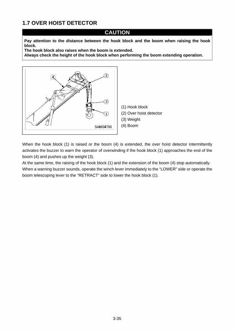
3-35
1.7 OVER HOIST DETECTOR
CAUTION
Pay attention to the distance between the hook block and the boom when raising the hook block. The hook block also raises when the boom is extended. Always check the height of the hook block when performing the boom extending operation.
(1) Hook block
(2) Over hoist detector
(3) Weight
(4) Boom
When the hook block (1) is raised or the boom (4) is extended, the over hoist detector intermittently
activates the buzzer to warn the operator of overwinding if the hook block (1) approaches the end of the
boom (4) and pushes up the weight (3).
At the same time, the raising of the hook block (1) and the extension of the boom (4) stop automatically.
When a warning buzzer sounds, operate the winch lever immediately to the “LOWER” side or operate the
boom telescoping lever to the “RETRACT” side to lower the hook block (1).
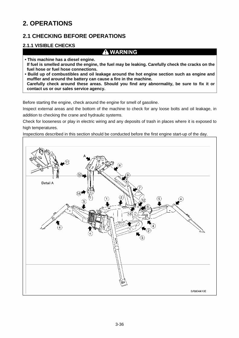
3-36
2. OPERATIONS
2.1 CHECKING BEFORE OPERATIONS
2.1.1 VISIBLE CHECKS
• This machine has a diesel engine. If fuel is smelled around the engine, the fuel may be leaking. Carefully check the cracks on the fuel hose or fuel hose connections.
• Build up of combustibles and oil leakage around the hot engine section such as engine and muffler and around the battery can cause a fire in the machine. Carefully check around these areas. Should you find any abnormality, be sure to fix it or contact us or our sales service agency.
Before starting the engine, check around the engine for smell of gasoline.
Inspect external areas and the bottom of the machine to check for any loose bolts and oil leakage, in
addition to checking the crane and hydraulic systems.
Check for looseness or play in electric wiring and any deposits of trash in places where it is exposed to
high temperatures.
Inspections described in this section should be conducted before the first engine start-up of the day.
3-37
[1] INSPECTION AROUND ENGINE
Check for and remove any accumulation or deposits of inflammable items including fallen leaves,
wastepaper, trash, oil or grease in high temperature areas such as engine and muffler.
Check for fuel or oil leakage from the engine and repair if necessary.
Check for slack wiring or loose connections. Also check for any trace of burning around the starter,
alternator or battery and repair any abnormality that may be found.
[2] INSPECTION OF HYDRAULIC SYSTEM OF UNDERCARRIAGE
(Travel motor, control valve, hydraulic oil tank, and hose joint)
Check for loose pipe connections or oil leakage and repair any abnormality.
[3] INSPECTION OF UNDERCARRIAGE (rubber track, track roller, sprocket and idler)
Check for damage, wear and loose track rollers. Repair any abnormality. Check for loose or missing
bolts and retighten as necessary. For details, see “OPERATION, 3. HANDLING OF RUBBER TRACK”.
[4] INSPECTION OF OUTRIGGER
Check for cracks and bent or damaged parts. Check wear of support pins etc, and repair as necessary.
[5] INSPECTION OF OUTRIGGER CYLINDER
Check for loose pipe connections, oil leakage, wear or damage of support pins etc, and repair as
necessary.
[6] INSPECTION OF POST
Check for cracks, and bent or damaged parts. Also check for loose post and slew ring mounting bolts,
loose swing system speed reducer mounting bolts, loose pipe connections or oil leakage. Repair any
abnormality detected.
[7] INSPECTION OF DERRICK CYLINDER
Check for loose pipe connections, oil leakage, wear or damage of support pins etc, and repair as
necessary.
[8] INSPECTION OF BOOM
Check for cracks, bent or damage sections in all areas, and check wear of support pins etc, and repair
as necessary.
Check for loose mounting bolts of the support pin lock plate portion and tighten it as necessary.
[9] INSPECTION OF TELESCOPE CYLINDER
Check for loose pipe connections or oil leakage and repair as necessary.
[10] INSPECTION OF WIRE ROPE
Check for damage, deformation, wear, twists, kinks and corrosion and replace where necessary. For
details, see “OPERATION, 4. HANDLING of WIRE ROPE”.

3-38
[11] INSPECTION OF OVER-HOIST PREVENTIVE DEVICE
Check the wire rope of over-hoist weight for damage etc, and replace it as necessary.
[12] INSPECTION OF WINCH MOTOR
Check for loose pipe connections, oil leakage or loose mounting bolts, and repair as necessary.
[13] INSPECTION OF WINCH DRUM
Check the drum for cracks, bending or damage and repair it as necessary. Check hoisting wire rope for
disorderly winding and repair it as necessary
[14] INSPECTION OF HOOK BLOCK
Check hook and sheaves for cracks, bending or damage and repair where necessary. Check hook and
sheaves for proper rotation and repair as necessary.
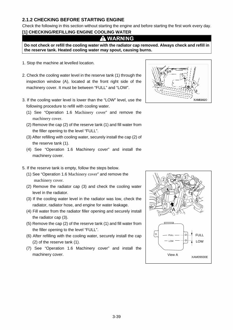
3-39
2.1.2 CHECKING BEFORE STARTING ENGINE Check the following in this section without starting the engine and before starting the first work every day.
[1] CHECKING/REFILLING ENGINE COOLING WATER
Do not check or refill the cooling water with the radiator cap removed. Always check and refill in the reserve tank. Heated cooling water may spout, causing burns.
1. Stop the machine at levelled location.
2. Check the cooling water level in the reserve tank (1) through the
inspection window (A), located at the front right side of the
machinery cover. It must be between “FULL” and “LOW”.
3. If the cooling water level is lower than the “LOW” level, use the
following procedure to refill with cooling water.
(1) See “Operation 1.6 Machinery cover” and remove the
machinery cover. (2) Remove the cap (2) of the reserve tank (1) and fill water from
the filler opening to the level “FULL”.
(3) After refilling with cooling water, securely install the cap (2) of
the reserve tank (1).
(4) See “Operation 1.6 Machinery cover” and install the
machinery cover.
5. If the reserve tank is empty, follow the steps below.
(1) See “Operation 1.6 Machinery cover” and remove the
machinery cover. (2) Remove the radiator cap (3) and check the cooling water
level in the radiator.
(3) If the cooling water level in the radiator was low, check the
radiator, radiator hose, and engine for water leakage.
(4) Fill water from the radiator filler opening and securely install
the radiator cap (3).
(5) Remove the cap (2) of the reserve tank (1) and fill water from
the filler opening to the level “FULL”.
(6) After refilling with the cooling water, securely install the cap
(2) of the reserve tank (1).
(7) See “Operation 1.6 Machinery cover” and install the
machinery cover.
1
32
FULLFULL
LOW
View A
LOW
XAM09930E
A
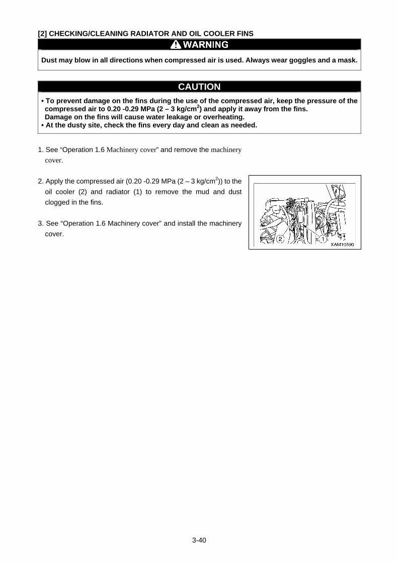
3-40
[2] CHECKING/CLEANING RADIATOR AND OIL COOLER FINS
Dust may blow in all directions when compressed air is used. Always wear goggles and a mask.
CAUTION
• To prevent damage on the fins during the use of the compressed air, keep the pressure of the compressed air to 0.20 -0.29 MPa (2 – 3 kg/cm2) and apply it away from the fins. Damage on the fins will cause water leakage or overheating.
• At the dusty site, check the fins every day and clean as needed.
1. See “Operation 1.6 Machinery cover” and remove the machinery cover.
2. Apply the compressed air (0.20 -0.29 MPa (2 – 3 kg/cm2)) to the
oil cooler (2) and radiator (1) to remove the mud and dust
clogged in the fins.
3. See “Operation 1.6 Machinery cover” and install the machinery
cover.
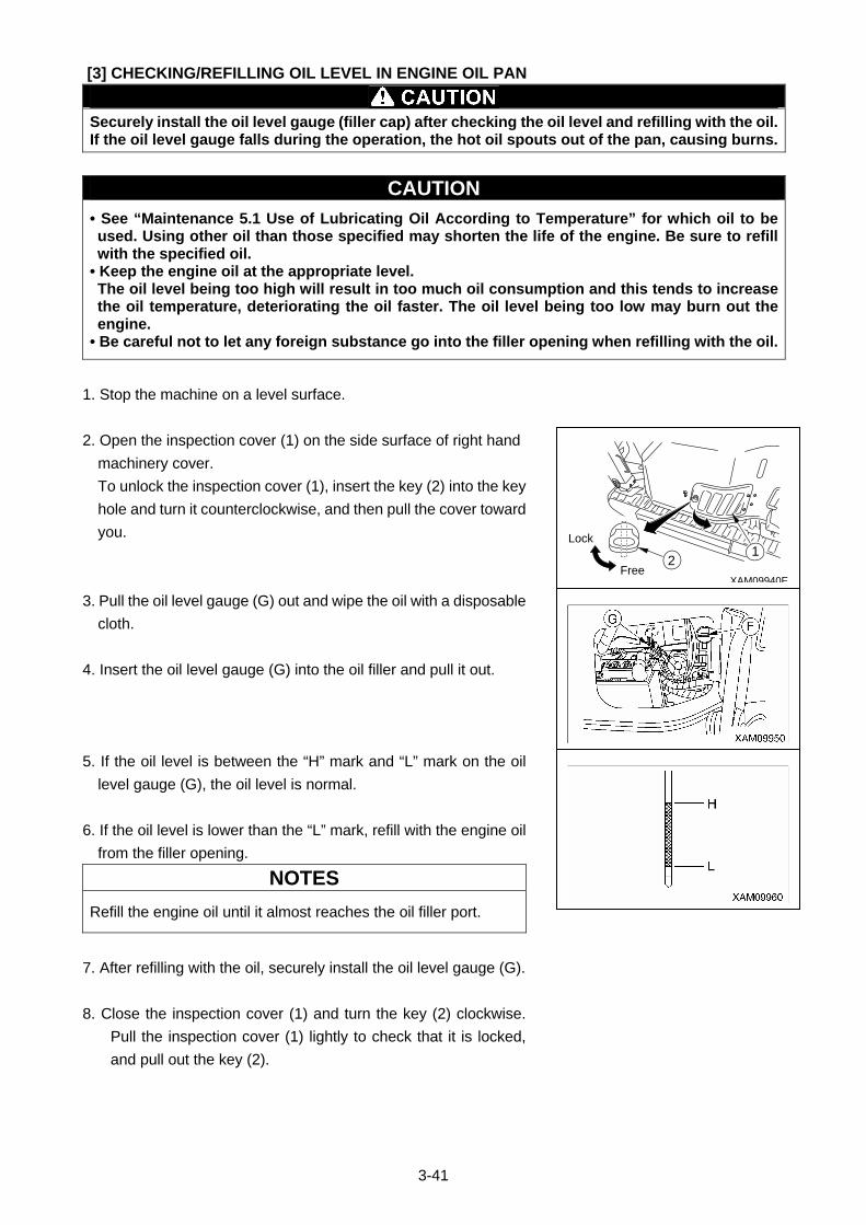
3-41
[3] CHECKING/REFILLING OIL LEVEL IN ENGINE OIL PAN
Securely install the oil level gauge (filler cap) after checking the oil level and refilling with the oil. If the oil level gauge falls during the operation, the hot oil spouts out of the pan, causing burns.
CAUTION
• See “Maintenance 5.1 Use of Lubricating Oil According to Temperature” for which oil to be used. Using other oil than those specified may shorten the life of the engine. Be sure to refill with the specified oil.
• Keep the engine oil at the appropriate level. The oil level being too high will result in too much oil consumption and this tends to increase the oil temperature, deteriorating the oil faster. The oil level being too low may burn out the engine.
• Be careful not to let any foreign substance go into the filler opening when refilling with the oil.
1. Stop the machine on a level surface.
2. Open the inspection cover (1) on the side surface of right hand
machinery cover.
To unlock the inspection cover (1), insert the key (2) into the key
hole and turn it counterclockwise, and then pull the cover toward
you.
3. Pull the oil level gauge (G) out and wipe the oil with a disposable
cloth.
4. Insert the oil level gauge (G) into the oil filler and pull it out.
5. If the oil level is between the “H” mark and “L” mark on the oil
level gauge (G), the oil level is normal.
6. If the oil level is lower than the “L” mark, refill with the engine oil
from the filler opening.
NOTES
Refill the engine oil until it almost reaches the oil filler port.
7. After refilling with the oil, securely install the oil level gauge (G).
8. Close the inspection cover (1) and turn the key (2) clockwise.
Pull the inspection cover (1) lightly to check that it is locked,
and pull out the key (2).
XAM09940EFree
Lock1
2
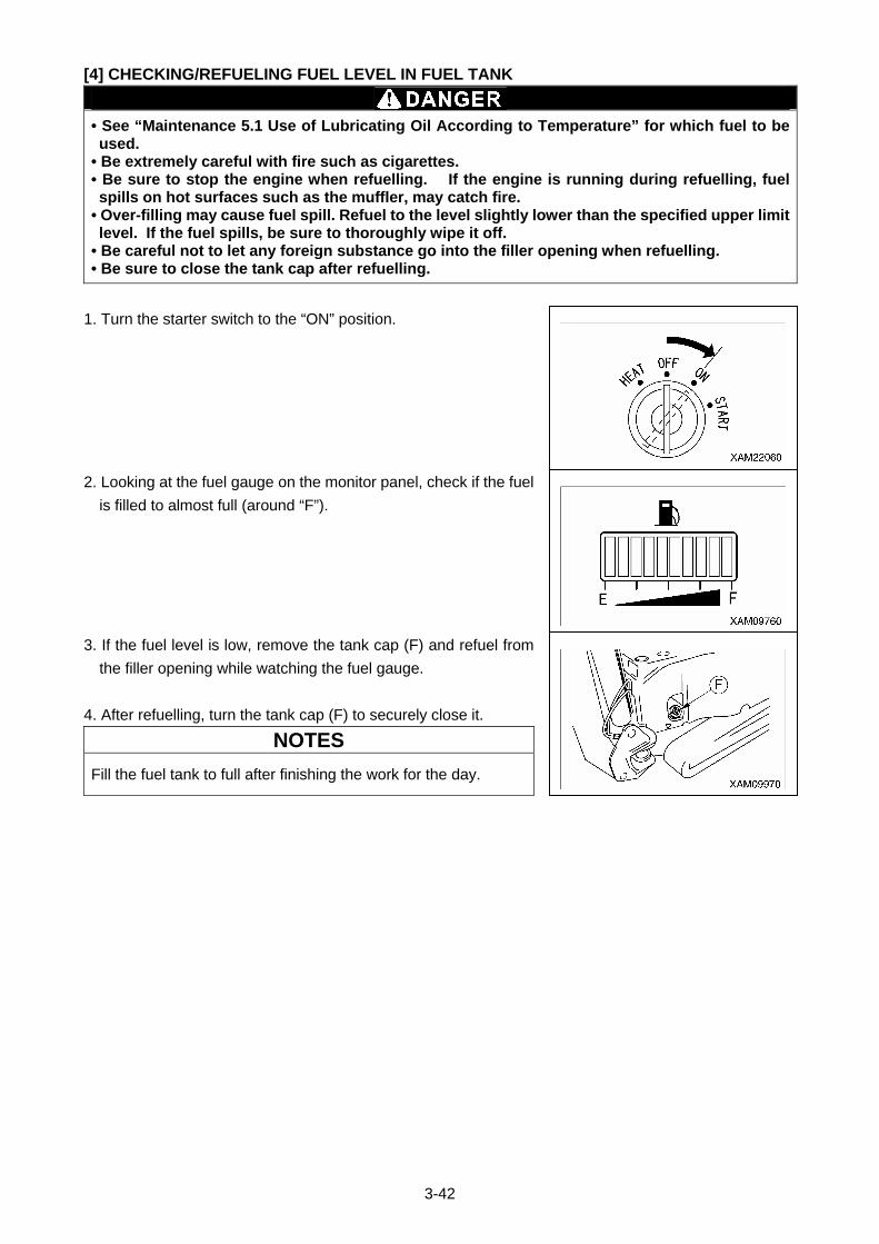
3-42
[4] CHECKING/REFUELING FUEL LEVEL IN FUEL TANK
• See “Maintenance 5.1 Use of Lubricating Oil According to Temperature” for which fuel to be used.
• Be extremely careful with fire such as cigarettes. • Be sure to stop the engine when refuelling. If the engine is running during refuelling, fuel spills on hot surfaces such as the muffler, may catch fire.
• Over-filling may cause fuel spill. Refuel to the level slightly lower than the specified upper limit level. If the fuel spills, be sure to thoroughly wipe it off.
• Be careful not to let any foreign substance go into the filler opening when refuelling. • Be sure to close the tank cap after refuelling.
1. Turn the starter switch to the “ON” position.
2. Looking at the fuel gauge on the monitor panel, check if the fuel
is filled to almost full (around “F”).
3. If the fuel level is low, remove the tank cap (F) and refuel from
the filler opening while watching the fuel gauge.
4. After refuelling, turn the tank cap (F) to securely close it.
NOTES
Fill the fuel tank to full after finishing the work for the day.
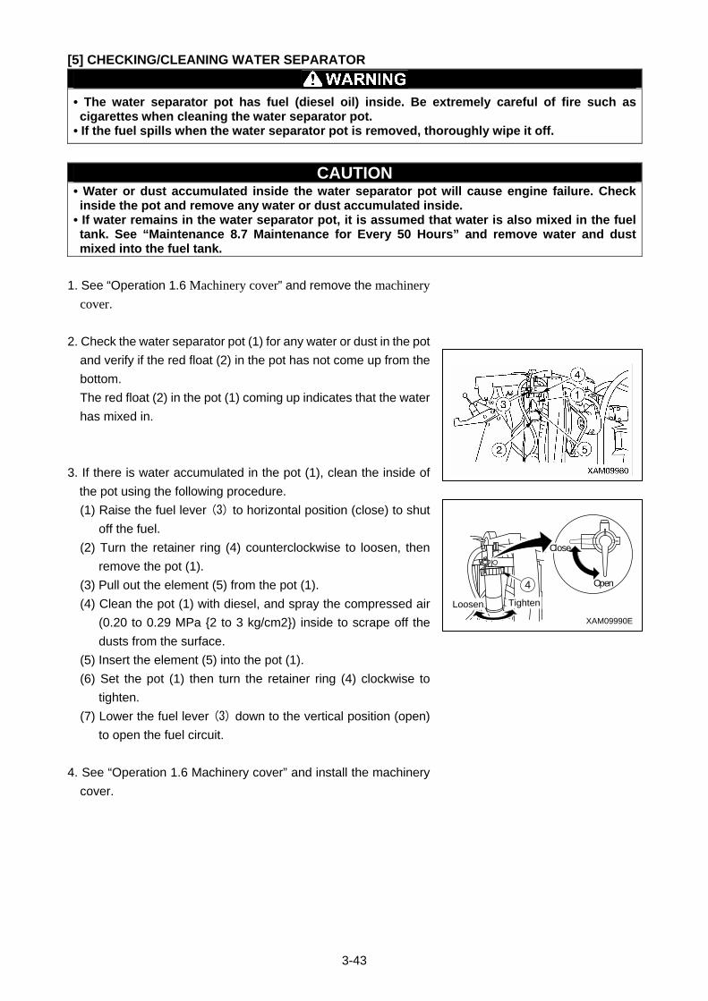
3-43
[5] CHECKING/CLEANING WATER SEPARATOR
• The water separator pot has fuel (diesel oil) inside. Be extremely careful of fire such as cigarettes when cleaning the water separator pot.
• If the fuel spills when the water separator pot is removed, thoroughly wipe it off.
CAUTION • Water or dust accumulated inside the water separator pot will cause engine failure. Check inside the pot and remove any water or dust accumulated inside.
• If water remains in the water separator pot, it is assumed that water is also mixed in the fuel tank. See “Maintenance 8.7 Maintenance for Every 50 Hours” and remove water and dust mixed into the fuel tank.
1. See “Operation 1.6 Machinery cover” and remove the machinery cover.
2. Check the water separator pot (1) for any water or dust in the pot
and verify if the red float (2) in the pot has not come up from the
bottom.
The red float (2) in the pot (1) coming up indicates that the water
has mixed in.
3. If there is water accumulated in the pot (1), clean the inside of
the pot using the following procedure.
(1) Raise the fuel lever (3) to horizontal position (close) to shut
off the fuel.
(2) Turn the retainer ring (4) counterclockwise to loosen, then
remove the pot (1).
(3) Pull out the element (5) from the pot (1).
(4) Clean the pot (1) with diesel, and spray the compressed air
(0.20 to 0.29 MPa {2 to 3 kg/cm2}) inside to scrape off the
dusts from the surface.
(5) Insert the element (5) into the pot (1).
(6) Set the pot (1) then turn the retainer ring (4) clockwise to
tighten.
(7) Lower the fuel lever (3) down to the vertical position (open)
to open the fuel circuit.
4. See “Operation 1.6 Machinery cover” and install the machinery
cover.
XAM09990E
4 Open
Loosen Tighten
Close
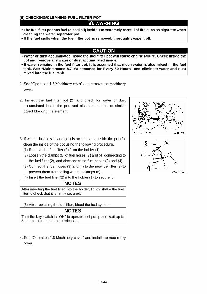
3-44
[6] CHECKING/CLEANING FUEL FILTER POT
• The fuel filter pot has fuel (diesel oil) inside. Be extremely careful of fire such as cigarette when cleaning the water separator pot.
• If the fuel spills when the fuel filter pot is removed, thoroughly wipe it off.
CAUTION • Water or dust accumulated inside the fuel filter pot will cause engine failure. Check inside the pot and remove any water or dust accumulated inside.
• If water remains in the fuel filter pot, it is assumed that much water is also mixed in the fuel tank. See “Maintenance 8.7 Maintenance for Every 50 Hours” and eliminate water and dust mixed into the fuel tank.
1. See “Operation 1.6 Machinery cover” and remove the machinery cover.
2. Inspect the fuel filter pot (2) and check for water or dust
accumulated inside the pot, and also for the dust or similar
object blocking the element.
3. If water, dust or similar object is accumulated inside the pot (2),
clean the inside of the pot using the following procedure.
(1) Remove the fuel filter (2) from the holder (1).
(2) Loosen the clamps (5) of fuel hoses (3) and (4) connecting to
the fuel filter (2), and disconnect the fuel hoses (3) and (4).
(3) Connect the fuel hoses (3) and (4) to the new fuel filter (2) to
prevent them from falling with the clamps (5).
(4) Insert the fuel filter (2) into the holder (1) to secure it.
NOTES
After inserting the fuel filter into the holder, lightly shake the fuel filter to check that it is firmly secured.
(5) After replacing the fuel filter, bleed the fuel system.
NOTES
Turn the key switch to “ON” to operate fuel pump and wait up to 5 minutes for the air to be released.
4. See “Operation 1.6 Machinery cover” and install the machinery
cover.
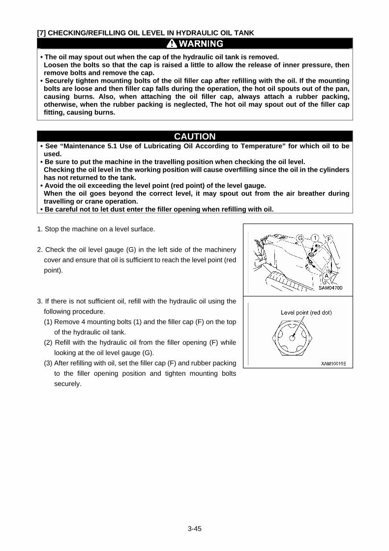
3-45
[7] CHECKING/REFILLING OIL LEVEL IN HYDRAULIC OIL TANK
• The oil may spout out when the cap of the hydraulic oil tank is removed. Loosen the bolts so that the cap is raised a little to allow the release of inner pressure, then remove bolts and remove the cap.
• Securely tighten mounting bolts of the oil filler cap after refilling with the oil. If the mounting bolts are loose and then filler cap falls during the operation, the hot oil spouts out of the pan, causing burns. Also, when attaching the oil filler cap, always attach a rubber packing, otherwise, when the rubber packing is neglected, The hot oil may spout out of the filler cap fitting, causing burns.
CAUTION • See “Maintenance 5.1 Use of Lubricating Oil According to Temperature” for which oil to be used.
• Be sure to put the machine in the travelling position when checking the oil level. Checking the oil level in the working position will cause overfilling since the oil in the cylinders has not returned to the tank.
• Avoid the oil exceeding the level point (red point) of the level gauge. When the oil goes beyond the correct level, it may spout out from the air breather during travelling or crane operation.
• Be careful not to let dust enter the filler opening when refilling with oil.
1. Stop the machine on a level surface.
2. Check the oil level gauge (G) in the left side of the machinery
cover and ensure that oil is sufficient to reach the level point (red
point).
3. If there is not sufficient oil, refill with the hydraulic oil using the
following procedure.
(1) Remove 4 mounting bolts (1) and the filler cap (F) on the top
of the hydraulic oil tank.
(2) Refill with the hydraulic oil from the filler opening (F) while
looking at the oil level gauge (G).
(3) After refilling with oil, set the filler cap (F) and rubber packing
to the filler opening position and tighten mounting bolts
securely.
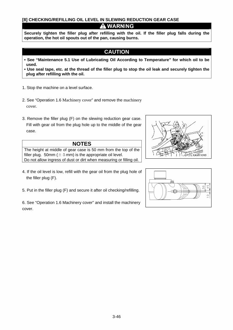
3-46
[8] CHECKING/REFILLING OIL LEVEL IN SLEWING REDUCTION GEAR CASE
Securely tighten the filler plug after refilling with the oil. If the filler plug falls during the operation, the hot oil spouts out of the pan, causing burns.
CAUTION • See “Maintenance 5.1 Use of Lubricating Oil According to Temperature” for which oil to be used.
• Use seal tape, etc. at the thread of the filler plug to stop the oil leak and securely tighten the plug after refilling with the oil.
1. Stop the machine on a level surface.
2. See “Operation 1.6 Machinery cover” and remove the machinery cover.
3. Remove the filler plug (F) on the slewing reduction gear case.
Fill with gear oil from the plug hole up to the middle of the gear
case.
NOTES The height at middle of gear case is 50 mm from the top of the filler plug. 50mm (±5mm) is the appropriate oil level. Do not allow ingress of dust or dirt when measuring or filling oil.
4. If the oil level is low, refill with the gear oil from the plug hole of
the filler plug (F).
5. Put in the filler plug (F) and secure it after oil checking/refilling.
6. See “Operation 1.6 Machinery cover” and install the machinery
cover.
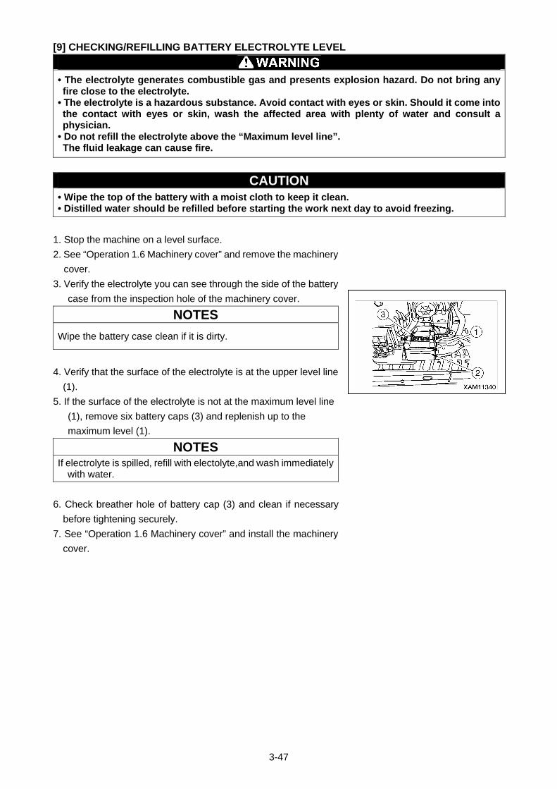
3-47
[9] CHECKING/REFILLING BATTERY ELECTROLYTE LEVEL
• The electrolyte generates combustible gas and presents explosion hazard. Do not bring any fire close to the electrolyte.
• The electrolyte is a hazardous substance. Avoid contact with eyes or skin. Should it come into the contact with eyes or skin, wash the affected area with plenty of water and consult a physician.
• Do not refill the electrolyte above the “Maximum level line”. The fluid leakage can cause fire.
CAUTION • Wipe the top of the battery with a moist cloth to keep it clean. • Distilled water should be refilled before starting the work next day to avoid freezing.
1. Stop the machine on a level surface.
2. See “Operation 1.6 Machinery cover” and remove the machinery
cover.
3. Verify the electrolyte you can see through the side of the battery
case from the inspection hole of the machinery cover.
NOTES
Wipe the battery case clean if it is dirty.
4. Verify that the surface of the electrolyte is at the upper level line
(1).
5. If the surface of the electrolyte is not at the maximum level line
(1), remove six battery caps (3) and replenish up to the
maximum level (1).
NOTES
If electrolyte is spilled, refill with electolyte,and wash immediately with water.
6. Check breather hole of battery cap (3) and clean if necessary
before tightening securely.
7. See “Operation 1.6 Machinery cover” and install the machinery
cover.
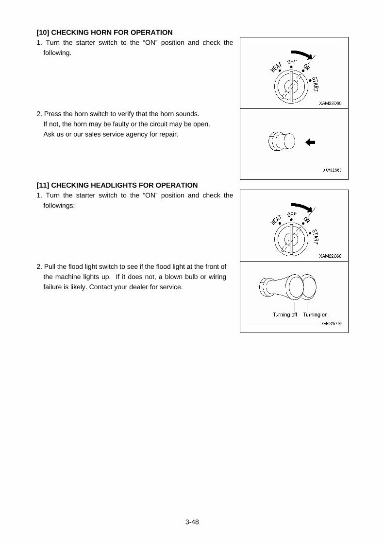
3-48
[10] CHECKING HORN FOR OPERATION
1. Turn the starter switch to the “ON” position and check the
following.
2. Press the horn switch to verify that the horn sounds.
If not, the horn may be faulty or the circuit may be open.
Ask us or our sales service agency for repair.
[11] CHECKING HEADLIGHTS FOR OPERATION
1. Turn the starter switch to the “ON” position and check the
followings:
2. Pull the flood light switch to see if the flood light at the front of
the machine lights up. If it does not, a blown bulb or wiring
failure is likely. Contact your dealer for service.
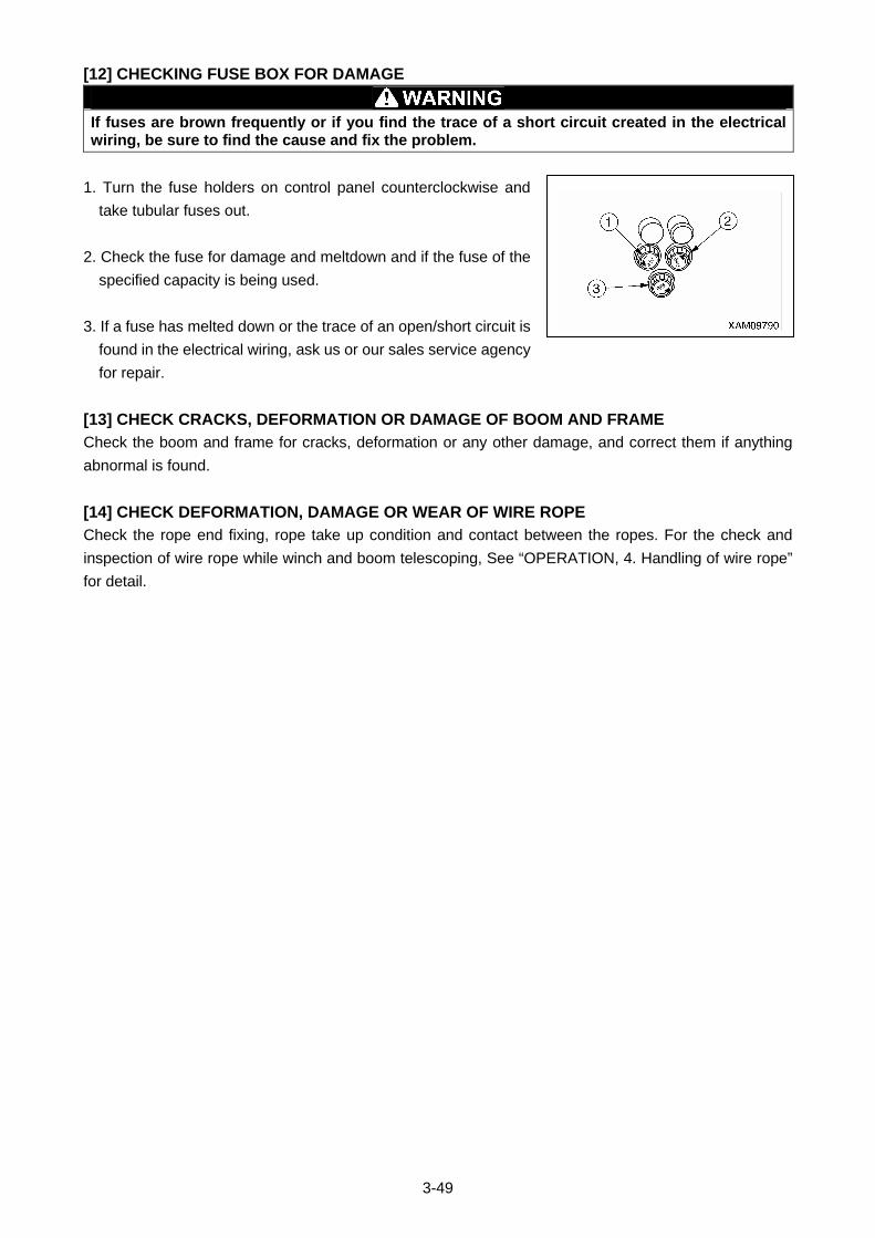
3-49
[12] CHECKING FUSE BOX FOR DAMAGE
If fuses are brown frequently or if you find the trace of a short circuit created in the electrical wiring, be sure to find the cause and fix the problem.
1. Turn the fuse holders on control panel counterclockwise and
take tubular fuses out.
2. Check the fuse for damage and meltdown and if the fuse of the
specified capacity is being used.
3. If a fuse has melted down or the trace of an open/short circuit is
found in the electrical wiring, ask us or our sales service agency
for repair.
[13] CHECK CRACKS, DEFORMATION OR DAMAGE OF BOOM AND FRAME
Check the boom and frame for cracks, deformation or any other damage, and correct them if anything
abnormal is found.
[14] CHECK DEFORMATION, DAMAGE OR WEAR OF WIRE ROPE
Check the rope end fixing, rope take up condition and contact between the ropes. For the check and
inspection of wire rope while winch and boom telescoping, See “OPERATION, 4. Handling of wire rope”
for detail.
3-50
2.1.3 CHECKING AFTER STARTING ENGINE Check the following in this section after starting the engine and before starting the first work every day.
CAUTION The checkups described in this section should be carried out after starting the machine. Refer to "Operation 2.2 Starting Engine" and later to execute the engine start up, travelling operations, outrigger operations and crane operations.
[1] CHECKING/ADJUSTING RUBBER TRACK TENSION
CAUTION • Set the outriggers and raise the rubber track for about 50 mm from the ground when checking/adjusting the tension of the rubber tracks.
• The standard tension of the rubber track is that the clearance between the wheels tread of the track roller at centre and the shoulder of the rubber track is 5 to 10 mm.
• If the tension is not sufficient even after injecting the grease, the rubber track or the sealing of the tension adjustment cylinder needs to be changed. Contact us or our sales service agency for the judgement of whether to replace, repair, or keep the rubber track.
The rubber tracks are worn out differently depending on the working conditions and soil quality. Regularly
check the wear and tension of the rubber tracks.
Especially, with the new machine or when a new part was installed, “initial slack” appears with 5 to 30
hours of driving after adjusting the tension to the specified value.
Adjust the tension frequently until the period of “initial slack” passes. This will prevent “rubber track from
coming off due to insufficient tension on the rubber track”.
[TENSION CHECK]
1. Move the left and right crawlers so that the junction of the rubber
track (indicated by M) comes to the top centre between the
axles.
2. See “Operation 2.12 Outrigger Setting Operation” to set the
outriggers and raise the crawlers for about 80mm from the
ground.
3. Measure the clearance between the wheel tread of the track
roller at centre and the shoulder of the rubber track.
NOTES
The clearance of 5 to 10 mm indicates the standard tension.
4. If the tension is out of the standard range, see the section of
tension adjustment on the next page to make adjustments.
3-51
[TENSION ADJUSTMENT]
If the “tension check” of the rubber track found the tension lower than standard tension of the rubber track,
make adjustments as described below.
Working with the loose rubber track (the tension of the rubber track at 15 mm or more) will cause run-off or
early wear of the core metal.
• LOOSE TENSION (INCREASE TENSION)
• Have a grease gun (pump) ready.
1. Remove the 2 bolts (2) and then remove inspection cover (1).
2. Inject the grease from the grease nipple (3) using the grease
gun.
3. Perform the following tasks to verify the proper tension.
(1) See “Operation 2.22 Outrigger Stowing Operation” to stow
the outriggers and lower the machine on the ground.
(2) Move the machine forward/backward.
(3) See “Operation 2.12 Outrigger Set Up Operation” to set the
outriggers and raise the crawlers again for about 80mm from
the ground.
4. Perform the “tension check” of the rubber track again.
If the tension is not appropriate, make another adjustment.
5. Install the inspection cover (1) to the original position and tighten
2 mounting bolts (2).
6. See “Operation 2.22 Outrigger Stowing Operation” to stow the
outriggers and lower the machine on the ground.
3-52
• TIGHT TENSION (DECREASE TENSION)
Inside the rubber track tension adjustment device, the grease is sealed. The grease is under high pressure due to the tension of the rubber track. Making adjustments without observing the following may cause the grease valve to fly away, resulting in serious accidents. • Do not loosen the grease valve for tension adjustment more than 1 turn. The grease valve may pop out.
• Do not place yourself right in front of the grease valve when adjusting the tension to avoid any danger.
1. Remove the 2 bolts (2) and then remove inspection cover (1).
2. Slowly loosen the grease valve (3) to drain the grease.
NOTES
When loosening the grease valve (3), do not loosen by more than one turn.
3. If the grease is not drained easily, perform the following to drain
the grease.
(1) See “Operation 2.22 Outrigger Stowing Operation” to stow
the outriggers and lower the machine on the ground.
(2) Move the machine forward/backward.
(3) See “Operation 2.12 Outrigger Set Up Operation” to set the
outriggers and raise the crawlers again for about 80mm from
the ground.
4. Tighten the grease valve (3).
5. Perform the “tension check” of the rubber track.
If the tension is not appropriate, make another adjustment.
6. Install the inspection cover (1) to the original position and tighten
2 mounting bolts (2).
7. See “Operation 2.22 Outrigger Stowing Operation” to stow the
outriggers and lower the machine on the ground.
3-53
[2] CHECKING RUBBER TRACKS FOR DAMAGE AND WEAR
CAUTION Contact us or our sales service agency for determining whether to replace, repair, or keep the rubber track.
The following condition requires the repair or replacement of the rubber track. Ask us or our sales service
agency for repair/replacement.
[LUG HEIGHT]
• When the lug height “a” decreases with wear, the traction force
drops.
Replace the rubber track when the lug height decreases to 5 mm
or lower with a new rubber track.
• When the lug is worn out and the steel cord inside the rubber
track is exposed for more than 2 links, replace the rubber track
with a new one.
[BROKEN STEEL CORD]
• If more than half of the steel cord layer is broken on one side,
replace the rubber track with a new one.
[FALLEN CORE METAL]
• If the core metal of the rubber track is fallen out at more than 1
location, change the rubber track with a new one.
[CRACKS]
•If there is a crack between rubber track lugs, change the rubber
track with a new one or repair the rubber track.
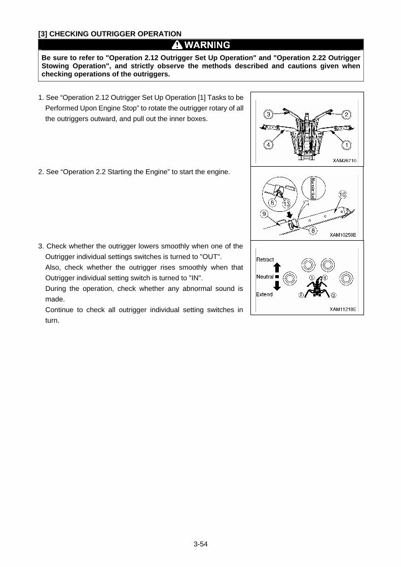
3-54
[3] CHECKING OUTRIGGER OPERATION
Be sure to refer to "Operation 2.12 Outrigger Set Up Operation" and "Operation 2.22 Outrigger Stowing Operation", and strictly observe the methods described and cautions given when checking operations of the outriggers.
1. See “Operation 2.12 Outrigger Set Up Operation [1] Tasks to be
Performed Upon Engine Stop” to rotate the outrigger rotary of all
the outriggers outward, and pull out the inner boxes.
2. See “Operation 2.2 Starting the Engine” to start the engine.
3. Check whether the outrigger lowers smoothly when one of the
Outrigger individual settings switches is turned to "OUT".
Also, check whether the outrigger rises smoothly when that
Outrigger individual setting switch is turned to "IN".
During the operation, check whether any abnormal sound is
made.
Continue to check all outrigger individual setting switches in
turn.
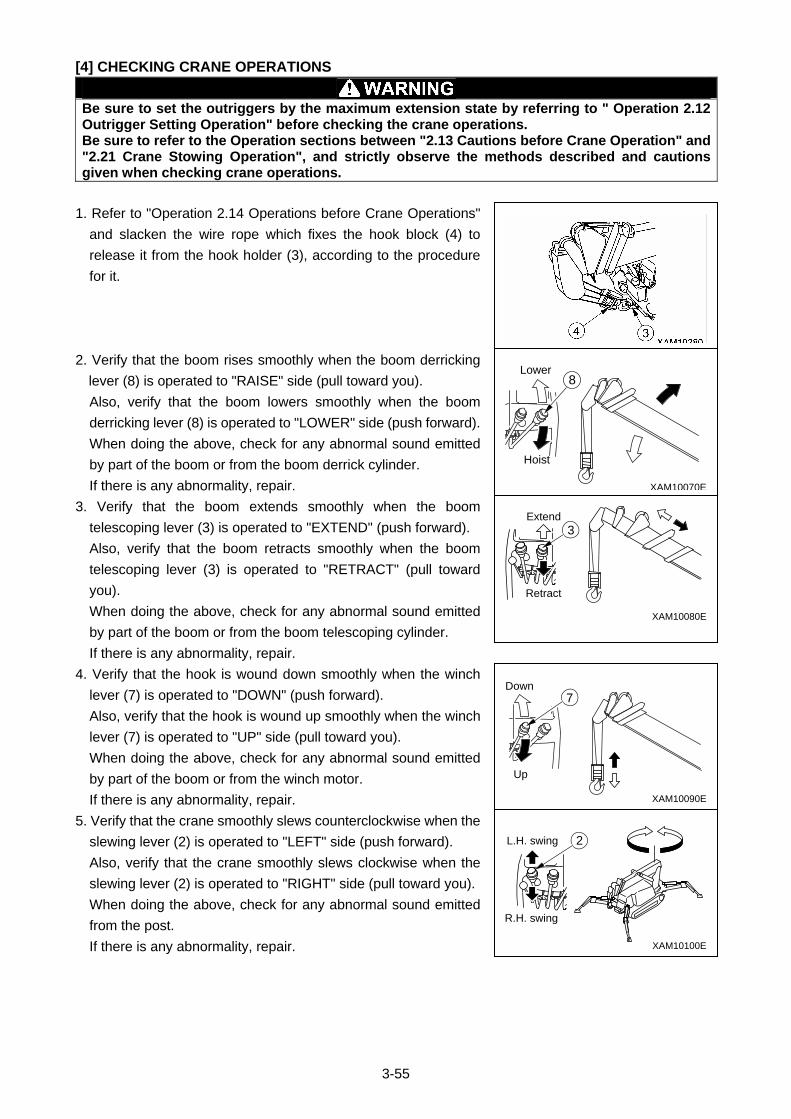
3-55
[4] CHECKING CRANE OPERATIONS
Be sure to set the outriggers by the maximum extension state by referring to " Operation 2.12 Outrigger Setting Operation" before checking the crane operations. Be sure to refer to the Operation sections between "2.13 Cautions before Crane Operation" and "2.21 Crane Stowing Operation", and strictly observe the methods described and cautions given when checking crane operations.
1. Refer to "Operation 2.14 Operations before Crane Operations"
and slacken the wire rope which fixes the hook block (4) to
release it from the hook holder (3), according to the procedure
for it.
2. Verify that the boom rises smoothly when the boom derricking
lever (8) is operated to "RAISE" side (pull toward you).
Also, verify that the boom lowers smoothly when the boom
derricking lever (8) is operated to "LOWER" side (push forward).
When doing the above, check for any abnormal sound emitted
by part of the boom or from the boom derrick cylinder.
If there is any abnormality, repair.
3. Verify that the boom extends smoothly when the boom
telescoping lever (3) is operated to "EXTEND" (push forward).
Also, verify that the boom retracts smoothly when the boom
telescoping lever (3) is operated to "RETRACT" (pull toward
you).
When doing the above, check for any abnormal sound emitted
by part of the boom or from the boom telescoping cylinder.
If there is any abnormality, repair.
4. Verify that the hook is wound down smoothly when the winch
lever (7) is operated to "DOWN" (push forward).
Also, verify that the hook is wound up smoothly when the winch
lever (7) is operated to "UP" side (pull toward you).
When doing the above, check for any abnormal sound emitted
by part of the boom or from the winch motor.
If there is any abnormality, repair.
5. Verify that the crane smoothly slews counterclockwise when the
slewing lever (2) is operated to "LEFT" side (push forward).
Also, verify that the crane smoothly slews clockwise when the
slewing lever (2) is operated to "RIGHT" side (pull toward you).
When doing the above, check for any abnormal sound emitted
from the post.
If there is any abnormality, repair.
L.H. swing
R.H. swing
2
XAM10100E
XAM10090E
Up
Down7
Extend
Retract
3
XAM10080E
XAM10070E
Hoist
Lower8
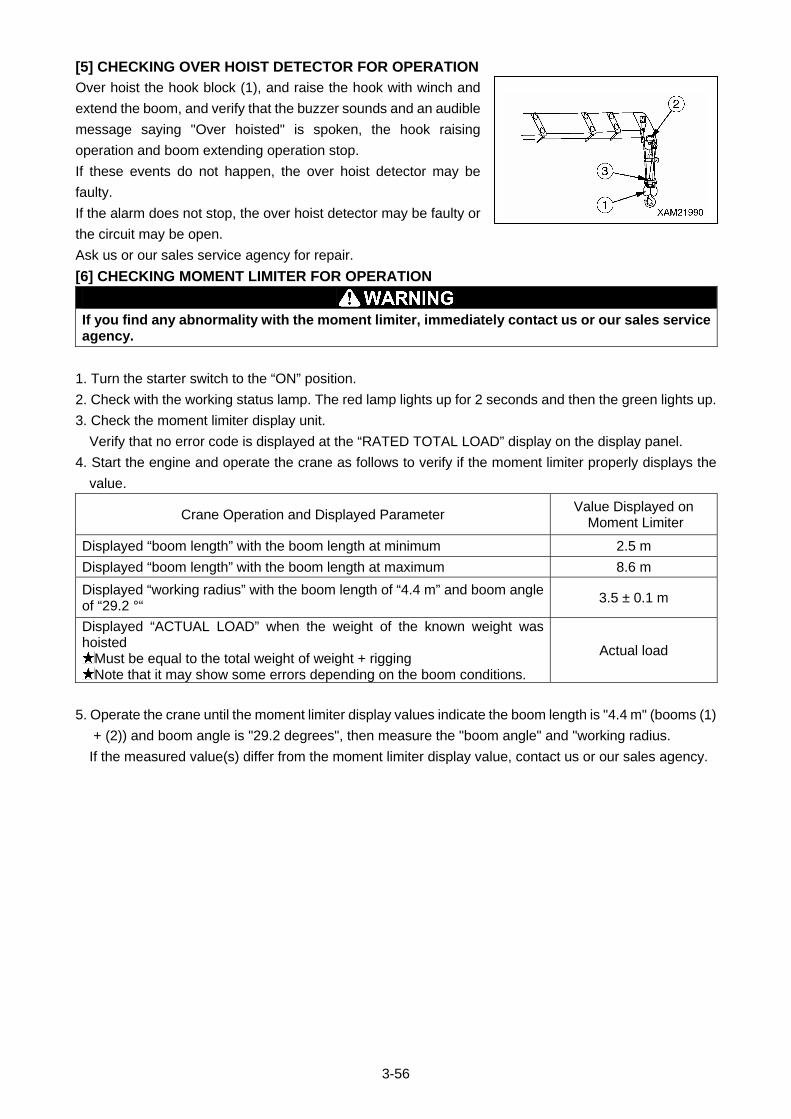
3-56
[5] CHECKING OVER HOIST DETECTOR FOR OPERATION
Over hoist the hook block (1), and raise the hook with winch and
extend the boom, and verify that the buzzer sounds and an audible
message saying "Over hoisted" is spoken, the hook raising
operation and boom extending operation stop.
If these events do not happen, the over hoist detector may be
faulty.
If the alarm does not stop, the over hoist detector may be faulty or
the circuit may be open.
Ask us or our sales service agency for repair.
[6] CHECKING MOMENT LIMITER FOR OPERATION
If you find any abnormality with the moment limiter, immediately contact us or our sales service agency.
1. Turn the starter switch to the “ON” position.
2. Check with the working status lamp. The red lamp lights up for 2 seconds and then the green lights up.
3. Check the moment limiter display unit.
Verify that no error code is displayed at the “RATED TOTAL LOAD” display on the display panel.
4. Start the engine and operate the crane as follows to verify if the moment limiter properly displays the
value.
Crane Operation and Displayed Parameter Value Displayed on
Moment Limiter
Displayed “boom length” with the boom length at minimum 2.5 m
Displayed “boom length” with the boom length at maximum 8.6 m
Displayed “working radius” with the boom length of “4.4 m” and boom angle of “29.2 °“
3.5 ± 0.1 m
Displayed “ACTUAL LOAD” when the weight of the known weight was hoisted
Must be equal to the total weight of weight + rigging Note that it may show some errors depending on the boom conditions.
Actual load
5. Operate the crane until the moment limiter display values indicate the boom length is "4.4 m" (booms (1)
+ (2)) and boom angle is "29.2 degrees", then measure the "boom angle" and "working radius.
If the measured value(s) differ from the moment limiter display value, contact us or our sales agency.
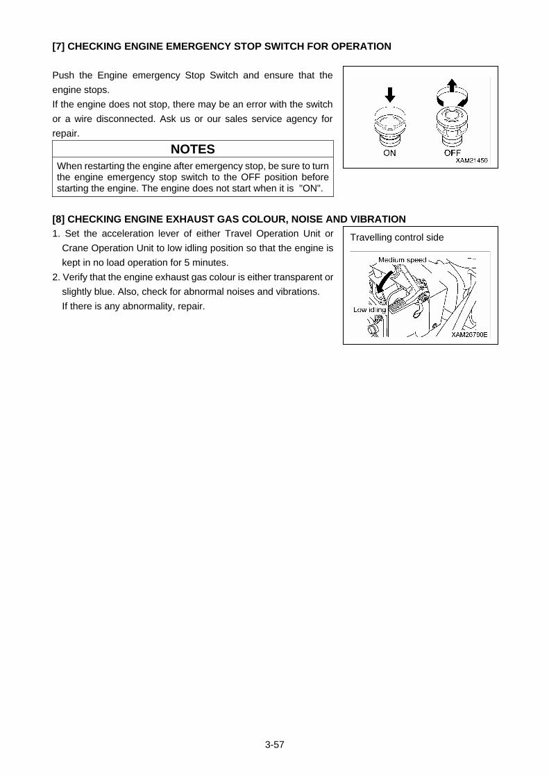
3-57
[7] CHECKING ENGINE EMERGENCY STOP SWITCH FOR OPERATION
Push the Engine emergency Stop Switch and ensure that the
engine stops.
If the engine does not stop, there may be an error with the switch
or a wire disconnected. Ask us or our sales service agency for
repair.
NOTES
When restarting the engine after emergency stop, be sure to turn the engine emergency stop switch to the OFF position before starting the engine. The engine does not start when it is "ON".
[8] CHECKING ENGINE EXHAUST GAS COLOUR, NOISE AND VIBRATION
1. Set the acceleration lever of either Travel Operation Unit or
Crane Operation Unit to low idling position so that the engine is
kept in no load operation for 5 minutes.
2. Verify that the engine exhaust gas colour is either transparent or
slightly blue. Also, check for abnormal noises and vibrations.
If there is any abnormality, repair.
Travelling control side
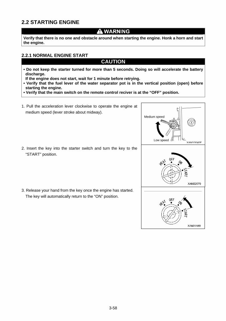
3-58
2.2 STARTING ENGINE
Verify that there is no one and obstacle around when starting the engine. Honk a horn and start the engine.
2.2.1 NORMAL ENGINE START
CAUTION • Do not keep the starter turned for more than 5 seconds. Doing so will accelerate the battery discharge. If the engine does not start, wait for 1 minute before retrying.
• Verify that the fuel lever of the water separator pot is in the vertical position (open) before starting the engine.
• Verify that the main switch on the remote control reciver is at the “OFF” position.
1. Pull the acceleration lever clockwise to operate the engine at
medium speed (lever stroke about midway).
2. Insert the key into the starter switch and turn the key to the
“START” position.
3. Release your hand from the key once the engine has started.
The key will automatically return to the “ON” position.
XAM10040ELow speed
Medium speed
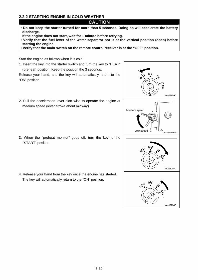
3-59
2.2.2 STARTING ENGINE IN COLD WEATHER
CAUTION • Do not keep the starter turned for more than 5 seconds. Doing so will accelerate the battery discharge. If the engine does not start, wait for 1 minute before retrying.
• Verify that the fuel lever of the water separator pot is at the vertical position (open) before starting the engine.
• Verify that the main switch on the remote control receiver is at the “OFF” position.
Start the engine as follows when it is cold.
1. Insert the key into the starter switch and turn the key to “HEAT”
(preheat) position. Keep the position the 3 seconds.
Release your hand, and the key will automatically return to the
“ON” position.
2. Pull the acceleration lever clockwise to operate the engine at
medium speed (lever stroke about midway).
3. When the “preheat monitor” goes off, turn the key to the
“START” position.
4. Release your hand from the key once the engine has started.
The key will automatically return to the “ON” position.
XAM10040ELow speed
Medium speed
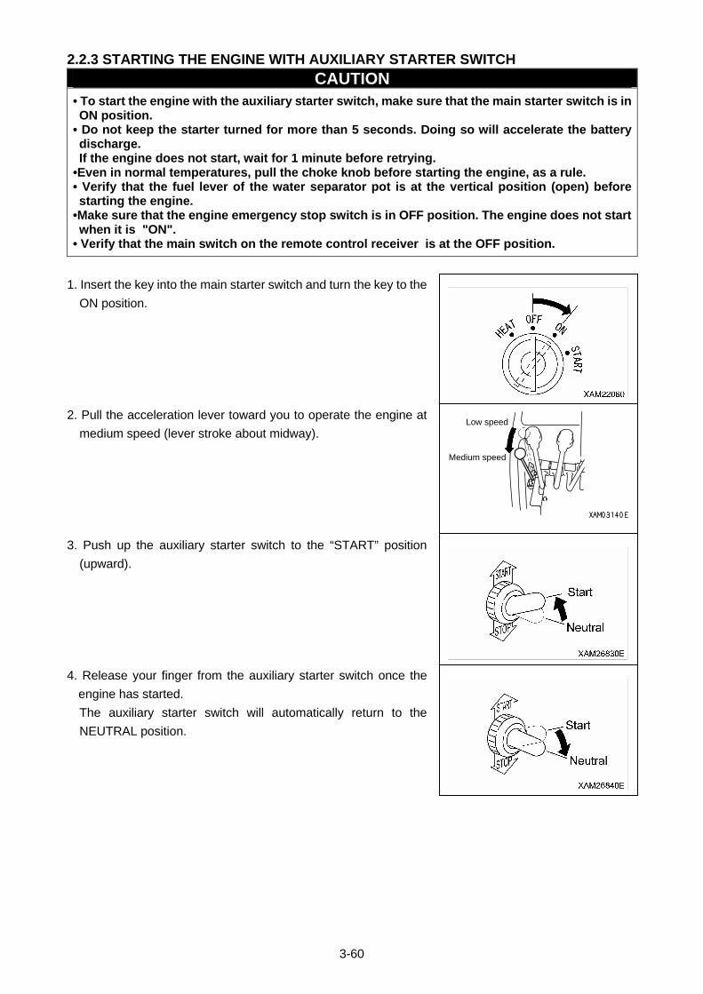
3-60
2.2.3 STARTING THE ENGINE WITH AUXILIARY STARTER SWITCH
CAUTION • To start the engine with the auxiliary starter switch, make sure that the main starter switch is in ON position.
• Do not keep the starter turned for more than 5 seconds. Doing so will accelerate the battery discharge. If the engine does not start, wait for 1 minute before retrying.
•Even in normal temperatures, pull the choke knob before starting the engine, as a rule. • Verify that the fuel lever of the water separator pot is at the vertical position (open) before starting the engine.
•Make sure that the engine emergency stop switch is in OFF position. The engine does not start when it is "ON".
• Verify that the main switch on the remote control receiver is at the OFF position.
1. Insert the key into the main starter switch and turn the key to the
ON position.
2. Pull the acceleration lever toward you to operate the engine at
medium speed (lever stroke about midway).
3. Push up the auxiliary starter switch to the “START” position
(upward).
4. Release your finger from the auxiliary starter switch once the
engine has started.
The auxiliary starter switch will automatically return to the
NEUTRAL position.
Low speed
Medium speed
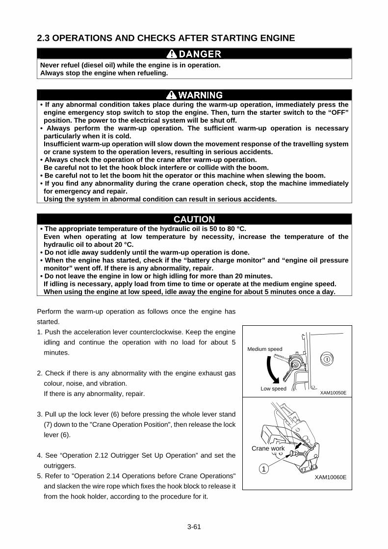
3-61
2.3 OPERATIONS AND CHECKS AFTER STARTING ENGINE
Never refuel (diesel oil) while the engine is in operation. Always stop the engine when refueling.
• If any abnormal condition takes place during the warm-up operation, immediately press the engine emergency stop switch to stop the engine. Then, turn the starter switch to the “OFF” position. The power to the electrical system will be shut off.
• Always perform the warm-up operation. The sufficient warm-up operation is necessary particularly when it is cold. Insufficient warm-up operation will slow down the movement response of the travelling system or crane system to the operation levers, resulting in serious accidents.
• Always check the operation of the crane after warm-up operation. Be careful not to let the hook block interfere or collide with the boom.
• Be careful not to let the boom hit the operator or this machine when slewing the boom. • If you find any abnormality during the crane operation check, stop the machine immediately for emergency and repair. Using the system in abnormal condition can result in serious accidents.
CAUTION • The appropriate temperature of the hydraulic oil is 50 to 80 °C. Even when operating at low temperature by necessity, increase the temperature of the hydraulic oil to about 20 °C.
• Do not idle away suddenly until the warm-up operation is done. • When the engine has started, check if the “battery charge monitor” and “engine oil pressure monitor” went off. If there is any abnormality, repair.
• Do not leave the engine in low or high idling for more than 20 minutes. If idling is necessary, apply load from time to time or operate at the medium engine speed. When using the engine at low speed, idle away the engine for about 5 minutes once a day.
Perform the warm-up operation as follows once the engine has
started.
1. Push the acceleration lever counterclockwise. Keep the engine
idling and continue the operation with no load for about 5
minutes.
2. Check if there is any abnormality with the engine exhaust gas
colour, noise, and vibration.
If there is any abnormality, repair.
3. Pull up the lock lever (6) before pressing the whole lever stand
(7) down to the "Crane Operation Position", then release the lock
lever (6).
4. See “Operation 2.12 Outrigger Set Up Operation” and set the
outriggers.
5. Refer to "Operation 2.14 Operations before Crane Operations"
and slacken the wire rope which fixes the hook block to release it
from the hook holder, according to the procedure for it.
XAM10050ELow speed
Medium speed
XAM10060E1
Crane work
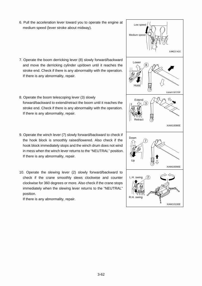
3-62
6. Pull the acceleration lever toward you to operate the engine at
medium speed (lever stroke about midway).
7. Operate the boom derricking lever (8) slowly forward/backward
and move the derricking cylinder up/down until it reaches the
stroke end. Check if there is any abnormality with the operation.
If there is any abnormality, repair.
8. Operate the boom telescoping lever (3) slowly
forward/backward to extend/retract the boom until it reaches the
stroke end. Check if there is any abnormality with the operation.
If there is any abnormality, repair.
9. Operate the winch lever (7) slowly forward/backward to check if
the hook block is smoothly raised/lowered. Also check if the
hook block immediately stops and the winch drum does not wind
in mess when the winch lever returns to the “NEUTRAL” position.
If there is any abnormality, repair.
10. Operate the slewing lever (2) slowly forward/backward to
check if the crane smoothly slews clockwise and counter
clockwise for 360 degrees or more. Also check if the crane stops
immediately when the slewing lever returns to the “NEUTRAL”
position.
If there is any abnormality, repair.
L.H. swing
R.H. swing
2
XAM10100E
XAM10090E
Up
Down7
Extend
Retract
3
XAM10080E
XAM10070E
Hoist
Lower8
Low speed
Medium speed
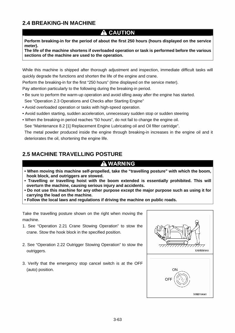
3-63
2.4 BREAKING-IN MACHINE
Perform breaking-in for the period of about the first 250 hours (hours displayed on the service meter). The life of the machine shortens if overloaded operation or task is performed before the various sections of the machine are used to the operation.
While this machine is shipped after thorough adjustment and inspection, immediate difficult tasks will
quickly degrade the functions and shorten the life of the engine and crane.
Perform the breaking-in for the first “250 hours” (time displayed on the service meter).
Pay attention particularly to the following during the breaking-in period.
• Be sure to perform the warm-up operation and avoid idling away after the engine has started.
See “Operation 2.3 Operations and Checks after Starting Engine”
• Avoid overloaded operation or tasks with high-speed operation.
• Avoid sudden starting, sudden acceleration, unnecessary sudden stop or sudden steering
• When the breaking-in period reaches “50 hours”, do not fail to change the engine oil.
See “Maintenance 8.2 [1] Replacement Engine Lubricating oil and Oil filter cartridge”.
The metal powder produced inside the engine through breaking-in increases in the engine oil and it
deteriorates the oil, shortening the engine life.
2.5 MACHINE TRAVELLING POSTURE
• When moving this machine self-propelled, take the “travelling posture” with which the boom, hook block, and outriggers are stowed.
• Travelling or travelling hoist with the boom extended is essentially prohibited. This will overturn the machine, causing serious injury and accidents.
• Do not use this machine for any other purpose except the major purpose such as using it for carrying the load on the machine.
• Follow the local laws and regulations if driving the machine on public roads.
Take the travelling posture shown on the right when moving the
machine.
1. See “Operation 2.21 Crane Stowing Operation” to stow the
crane. Stow the hook block in the specified position.
2. See “Operation 2.22 Outrigger Stowing Operation” to stow the
outriggers.
3. Verify that the emergency stop cancel switch is at the OFF
(auto) position.
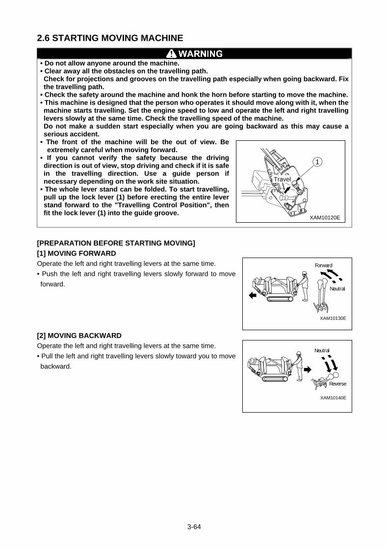
3-64
2.6 STARTING MOVING MACHINE
• Do not allow anyone around the machine. • Clear away all the obstacles on the travelling path. Check for projections and grooves on the travelling path especially when going backward. Fix the travelling path.
• Check the safety around the machine and honk the horn before starting to move the machine.• This machine is designed that the person who operates it should move along with it, when the machine starts travelling. Set the engine speed to low and operate the left and right travelling levers slowly at the same time. Check the travelling speed of the machine. Do not make a sudden start especially when you are going backward as this may cause a serious accident.
• The front of the machine will be the out of view. Be extremely careful when moving forward.
• If you cannot verify the safety because the driving direction is out of view, stop driving and check if it is safe in the travelling direction. Use a guide person if necessary depending on the work site situation.
• The whole lever stand can be folded. To start travelling, pull up the lock lever (1) before erecting the entire lever stand forward to the "Travelling Control Position", then fit the lock lever (1) into the guide groove.
[PREPARATION BEFORE STARTING MOVING]
[1] MOVING FORWARD
Operate the left and right travelling levers at the same time.
• Push the left and right travelling levers slowly forward to move
forward.
[2] MOVING BACKWARD
Operate the left and right travelling levers at the same time.
• Pull the left and right travelling levers slowly toward you to move
backward.
XAM10140E
Neutral
Reverse
XAM10130E
Forward
Neutral
XAM10120E
Travel
1
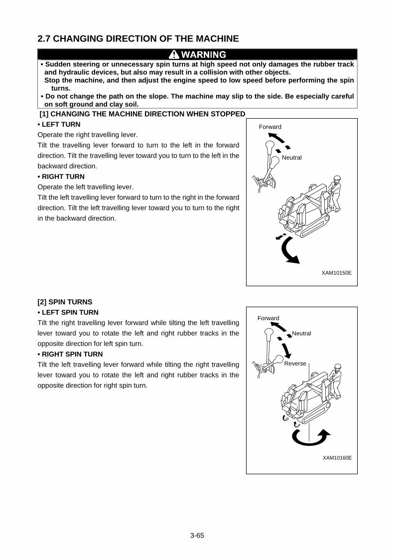
3-65
2.7 CHANGING DIRECTION OF THE MACHINE
• Sudden steering or unnecessary spin turns at high speed not only damages the rubber track and hydraulic devices, but also may result in a collision with other objects. Stop the machine, and then adjust the engine speed to low speed before performing the spin
turns. • Do not change the path on the slope. The machine may slip to the side. Be especially careful on soft ground and clay soil.
[1] CHANGING THE MACHINE DIRECTION WHEN STOPPED
• LEFT TURN
Operate the right travelling lever.
Tilt the travelling lever forward to turn to the left in the forward
direction. Tilt the travelling lever toward you to turn to the left in the
backward direction.
• RIGHT TURN
Operate the left travelling lever.
Tilt the left travelling lever forward to turn to the right in the forward
direction. Tilt the left travelling lever toward you to turn to the right
in the backward direction.
[2] SPIN TURNS
• LEFT SPIN TURN
Tilt the right travelling lever forward while tilting the left travelling
lever toward you to rotate the left and right rubber tracks in the
opposite direction for left spin turn.
• RIGHT SPIN TURN
Tilt the left travelling lever forward while tilting the right travelling
lever toward you to rotate the left and right rubber tracks in the
opposite direction for right spin turn.
XAM10150E
Forward
Neutral
XAM10160E
Forward
Reverse
Neutral
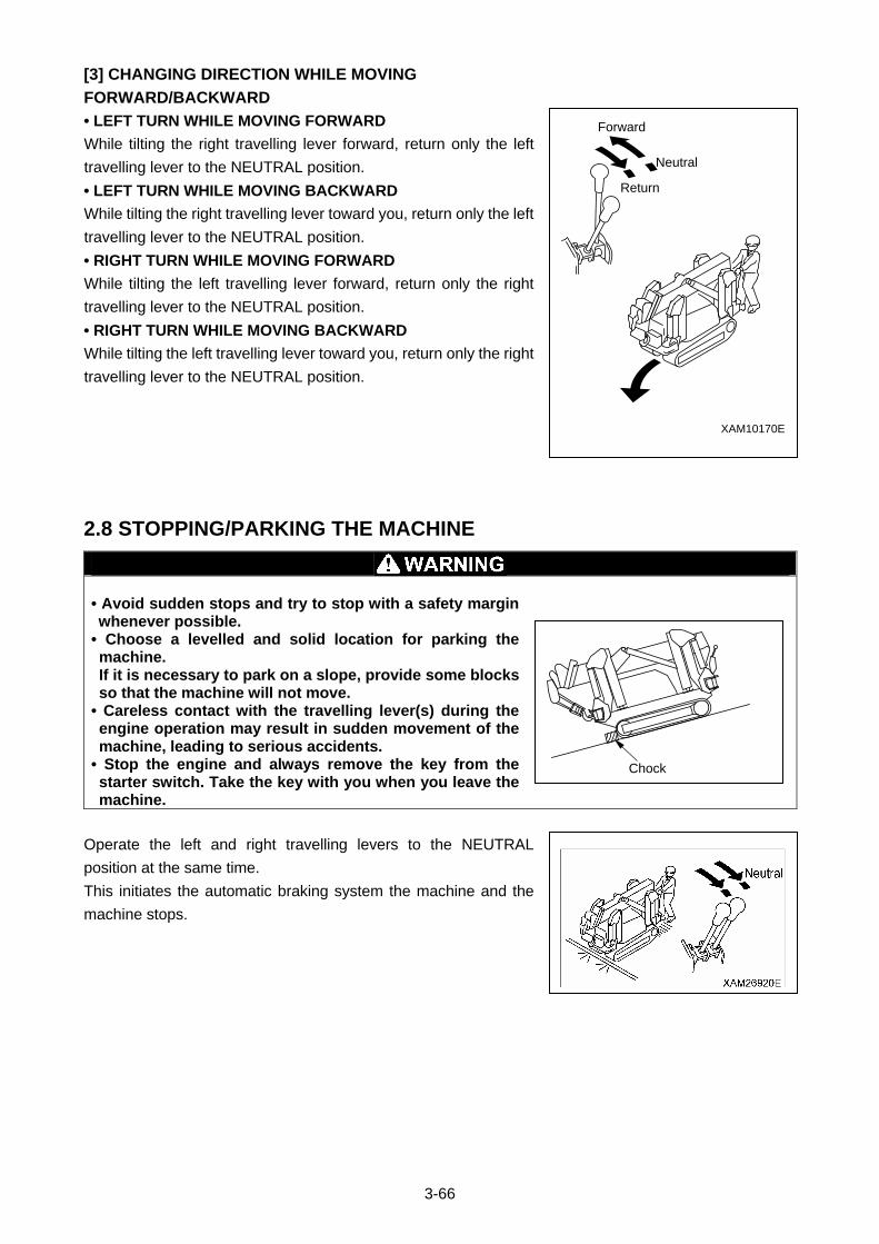
3-66
[3] CHANGING DIRECTION WHILE MOVING
FORWARD/BACKWARD
• LEFT TURN WHILE MOVING FORWARD
While tilting the right travelling lever forward, return only the left
travelling lever to the NEUTRAL position.
• LEFT TURN WHILE MOVING BACKWARD
While tilting the right travelling lever toward you, return only the left
travelling lever to the NEUTRAL position.
• RIGHT TURN WHILE MOVING FORWARD
While tilting the left travelling lever forward, return only the right
travelling lever to the NEUTRAL position.
• RIGHT TURN WHILE MOVING BACKWARD
While tilting the left travelling lever toward you, return only the right
travelling lever to the NEUTRAL position.
2.8 STOPPING/PARKING THE MACHINE
• Avoid sudden stops and try to stop with a safety margin whenever possible.
• Choose a levelled and solid location for parking the machine. If it is necessary to park on a slope, provide some blocks so that the machine will not move.
• Careless contact with the travelling lever(s) during the engine operation may result in sudden movement of the machine, leading to serious accidents.
• Stop the engine and always remove the key from the starter switch. Take the key with you when you leave the machine.
Operate the left and right travelling levers to the NEUTRAL
position at the same time.
This initiates the automatic braking system the machine and the
machine stops.
XAM10170E
Forward
Return
Neutral
XAM09630EChock
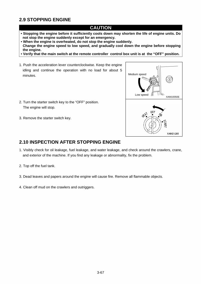
3-67
2.9 STOPPING ENGINE
CAUTION • Stopping the engine before it sufficiently cools down may shorten the life of engine units. Do not stop the engine suddenly except for an emergency.
• When the engine is overheated, do not stop the engine suddenly. Change the engine speed to low speed, and gradually cool down the engine before stopping the engine.
• Verify that the main switch at the remote controller control box unit is at the “OFF” position.
1. Push the acceleration lever counterclockwise. Keep the engine
idling and continue the operation with no load for about 5
minutes.
2. Turn the starter switch key to the “OFF” position.
The engine will stop.
3. Remove the starter switch key.
2.10 INSPECTION AFTER STOPPING ENGINE
1. Visibly check for oil leakage, fuel leakage, and water leakage, and check around the crawlers, crane,
and exterior of the machine. If you find any leakage or abnormality, fix the problem.
2. Top off the fuel tank.
3. Dead leaves and papers around the engine will cause fire. Remove all flammable objects.
4. Clean off mud on the crawlers and outriggers.
XAM10050ELow speed
Medium speed
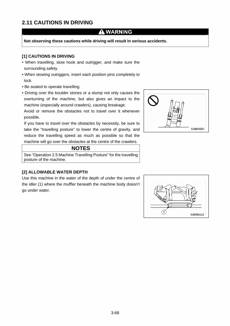
3-68
2.11 CAUTIONS IN DRIVING
Not observing these cautions while driving will result in serious accidents.
[1] CAUTIONS IN DRIVING
• When travelling, stow hook and outrigger, and make sure the
surrounding safety.
• When stowing outriggers, insert each position pins completely to
lock.
• Be seated to operate travelling.
• Driving over the boulder stones or a stump not only causes the
overturning of the machine, but also gives an impact to the
machine (especially around crawlers), causing breakage.
Avoid or remove the obstacles not to travel over it whenever
possible.
If you have to travel over the obstacles by necessity, be sure to
take the “travelling posture” to lower the centre of gravity, and
reduce the travelling speed as much as possible so that the
machine will go over the obstacles at the centre of the crawlers.
NOTES
See “Operation 2.5 Machine Travelling Posture” for the travelling posture of the machine.
[2] ALLOWABLE WATER DEPTH
Use this machine in the water of the depth of under the centre of
the idler (1) where the muffler beneath the machine body doesn’t
go under water.
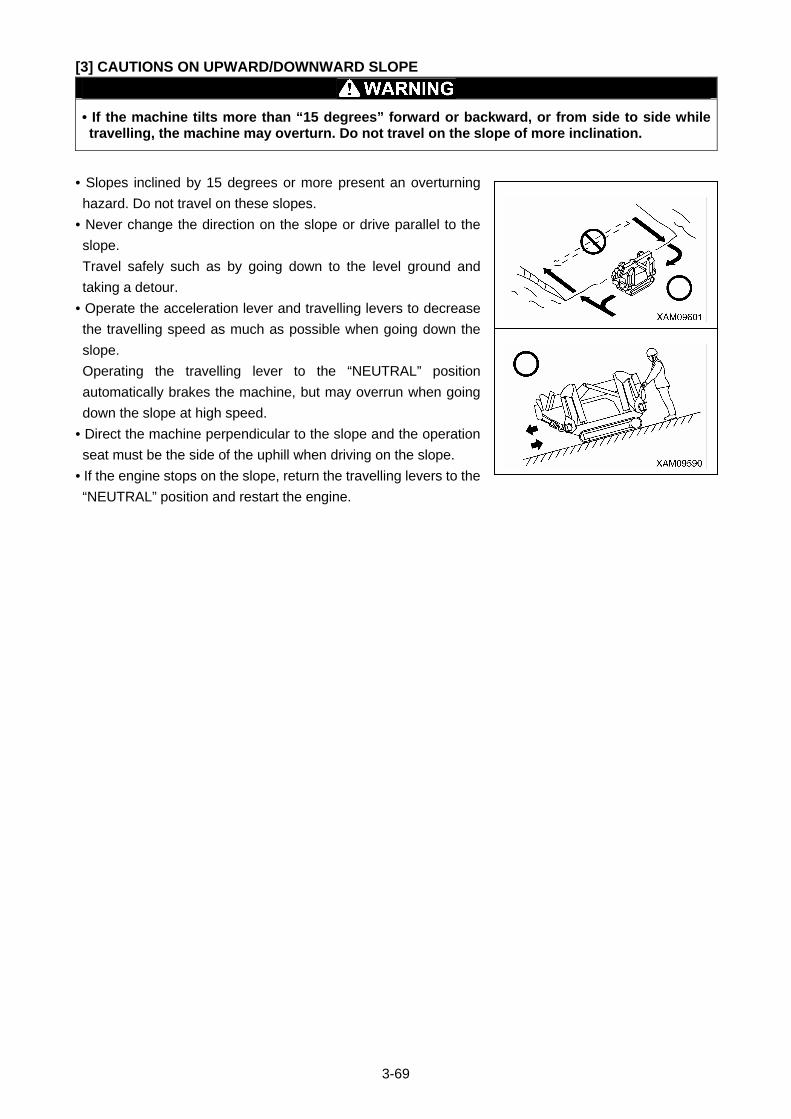
3-69
[3] CAUTIONS ON UPWARD/DOWNWARD SLOPE
• If the machine tilts more than “15 degrees” forward or backward, or from side to side while travelling, the machine may overturn. Do not travel on the slope of more inclination.
• Slopes inclined by 15 degrees or more present an overturning
hazard. Do not travel on these slopes.
• Never change the direction on the slope or drive parallel to the
slope.
Travel safely such as by going down to the level ground and
taking a detour.
• Operate the acceleration lever and travelling levers to decrease
the travelling speed as much as possible when going down the
slope.
Operating the travelling lever to the “NEUTRAL” position
automatically brakes the machine, but may overrun when going
down the slope at high speed.
• Direct the machine perpendicular to the slope and the operation
seat must be the side of the uphill when driving on the slope.
• If the engine stops on the slope, return the travelling levers to the
“NEUTRAL” position and restart the engine.

3-70
2.12 OUTRIGGER SETTING OPERATION
• GROUND FOR SETTING OUTRIGGERS Always set the outriggers on level, safe and solid ground. Performing the crane operation without setting the outriggers can contribute to the overturning of the machine.
• EXTENDING AND SETTING THE OUTRIGGERS • Keep people away from the machine when setting the outriggers. Close proximity to the machine may cause serious accidents such as getting caught between an outrigger and the machine main unit.
• Always monitor the level gauge when setting the outriggers. When the machine tilts to “3 degrees” or more, the overturning alarm buzzer sounds.
• Set the outriggers so that the rubber tracks are about 80 mm above the ground. After setting the outriggers, verify that all the four outriggers are securely set.
• The outriggers of this machine can be set flexibly according to the terrain. However, if the outriggers cannot be set in the “outrigger extended to maximum” state, perform the crane operation with the values given in the “Rated total load chart with outrigger extended to other than maximum” in the rated total load chart.
• When setting the outriggers, always maintain the outrigger rotary at the extension position, and insert the position pin into the end. Do not set the outriggers with the outrigger rotary stowed.
• When setting the outriggers, always extend the outrigger top. Avoid setting outriggers when the outrigger top is stowed.
• During outrigger switching operation, always keep the engine in middle or lower speed. When the engine is controlled to high speed, outriggers move too quickly which may result in serious accidents including tipping.
• To lift up the machine by control of the Outrigger individual setting switches, use the procedure as follows: • This machine has 4 outriggers. Be careful not to confuse the use of respective 4 Outrigger individual setting switch. Check both the outrigger numbers indicated in the control panel and number labels attached to each outrigger. A serious accident may occur if the outrigger numbers are confused.
• When you control 2 of the individual switches at one time, only 2 in the front (outriggers [(2)] and [(3)]) or only 2 in the rear (outriggers [(1)] and [(4)]) shall be operated at the same time. When 2 outriggers in either left or right side are controlled at the same time, these may extend very quickly to cause crane tipping.
• Use each of 4 Outrigger individual setting switches properly so that 4 outriggers extend evenly. Otherwise, when 2 outriggers in either left or right side extend very quickly, it may cause the machine to overturn.
• Any outrigger operations other than extending and retracting (e.g. inserting and extracting position pins) must be performed whilst engine is stopped. If any unauthorised person touches the outrigger setting switches, it may cause the outrigger cylinders to move suddenly, and result in a serious accident.
CAUTION For outrigger operations, set the travelling lever stand in the Travelling Operation Unit to the "Crane Operation Position". When the travelling lever stand is in "Travelling" position, any outrigger setting switches are not available for outrigger operations.
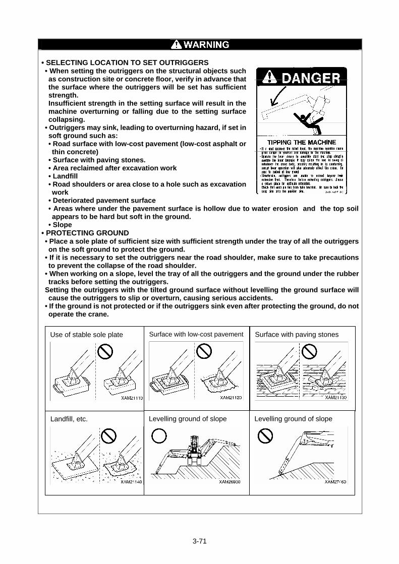
3-71
• SELECTING LOCATION TO SET OUTRIGGERS • When setting the outriggers on the structural objects such as construction site or concrete floor, verify in advance that the surface where the outriggers will be set has sufficient strength. Insufficient strength in the setting surface will result in the machine overturning or falling due to the setting surface collapsing.
• Outriggers may sink, leading to overturning hazard, if set in soft ground such as: • Road surface with low-cost pavement (low-cost asphalt or thin concrete)
• Surface with paving stones. • Area reclaimed after excavation work • Landfill • Road shoulders or area close to a hole such as excavation work
• Deteriorated pavement surface • Areas where under the pavement surface is hollow due to water erosion and the top soil appears to be hard but soft in the ground.
• Slope • PROTECTING GROUND • Place a sole plate of sufficient size with sufficient strength under the tray of all the outriggers on the soft ground to protect the ground.
• If it is necessary to set the outriggers near the road shoulder, make sure to take precautions to prevent the collapse of the road shoulder.
• When working on a slope, level the tray of all the outriggers and the ground under the rubber tracks before setting the outriggers.
Setting the outriggers with the tilted ground surface without levelling the ground surface will cause the outriggers to slip or overturn, causing serious accidents.
• If the ground is not protected or if the outriggers sink even after protecting the ground, do not operate the crane.
Levelling ground of slope
Use of stable sole plate Surface with low-cost pavement
Surface with paving stones
Landfill, etc.
Levelling ground of slope
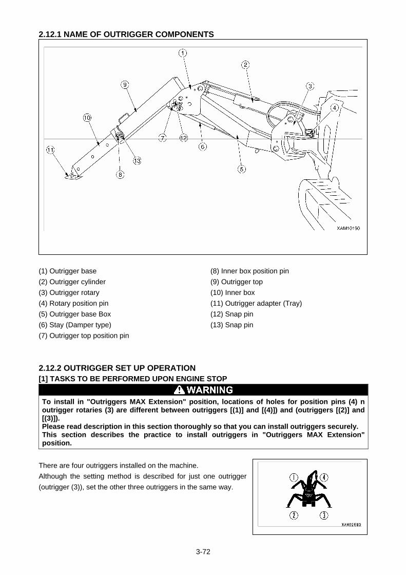
3-72
2.12.1 NAME OF OUTRIGGER COMPONENTS
(1) Outrigger base
(2) Outrigger cylinder
(3) Outrigger rotary
(4) Rotary position pin
(5) Outrigger base Box
(6) Stay (Damper type)
(7) Outrigger top position pin
(8) Inner box position pin
(9) Outrigger top
(10) Inner box
(11) Outrigger adapter (Tray)
(12) Snap pin
(13) Snap pin
2.12.2 OUTRIGGER SET UP OPERATION
[1] TASKS TO BE PERFORMED UPON ENGINE STOP
To install in "Outriggers MAX Extension" position, locations of holes for position pins (4) n outrigger rotaries (3) are different between outriggers [(1)] and [(4)]) and (outriggers [(2)] and [(3)]). Please read description in this section thoroughly so that you can install outriggers securely. This section describes the practice to install outriggers in "Outriggers MAX Extension" position.
There are four outriggers installed on the machine.
Although the setting method is described for just one outrigger
(outrigger (3)), set the other three outriggers in the same way.
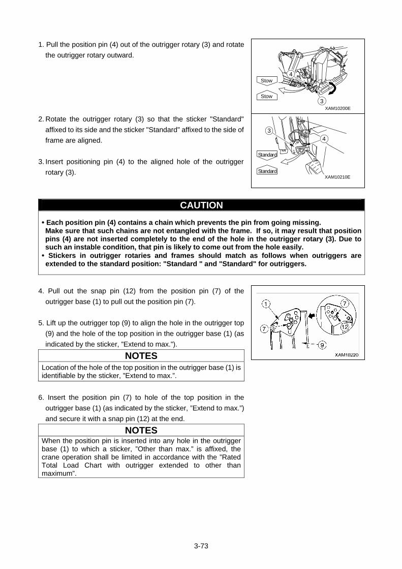
3-73
1. Pull the position pin (4) out of the outrigger rotary (3) and rotate
the outrigger rotary outward.
2. Rotate the outrigger rotary (3) so that the sticker "Standard"
affixed to its side and the sticker "Standard" affixed to the side of
frame are aligned.
3. Insert positioning pin (4) to the aligned hole of the outrigger
rotary (3).
CAUTION
• Each position pin (4) contains a chain which prevents the pin from going missing. Make sure that such chains are not entangled with the frame. If so, it may result that position pins (4) are not inserted completely to the end of the hole in the outrigger rotary (3). Due to such an instable condition, that pin is likely to come out from the hole easily.
• Stickers in outrigger rotaries and frames should match as follows when outriggers are extended to the standard position: "Standard " and "Standard" for outriggers.
4. Pull out the snap pin (12) from the position pin (7) of the
outrigger base (1) to pull out the position pin (7).
5. Lift up the outrigger top (9) to align the hole in the outrigger top
(9) and the hole of the top position in the outrigger base (1) (as
indicated by the sticker, ”Extend to max.”).
NOTES
Location of the hole of the top position in the outrigger base (1) is identifiable by the sticker, ”Extend to max.”.
6. Insert the position pin (7) to hole of the top position in the
outrigger base (1) (as indicated by the sticker, ”Extend to max.”)
and secure it with a snap pin (12) at the end.
NOTES When the position pin is inserted into any hole in the outrigger base (1) to which a sticker, ”Other than max.” is affixed, the crane operation shall be limited in accordance with the ”Rated Total Load Chart with outrigger extended to other than maximum”.
XAM10210E
43
Standard
Standard
XAM10200E
3
4
Stow
Stow
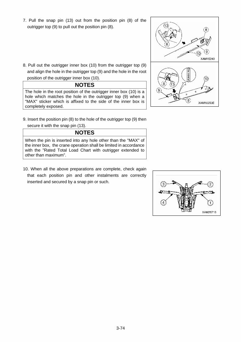
3-74
7. Pull the snap pin (13) out from the position pin (8) of the
outrigger top (9) to pull out the position pin (8).
8. Pull out the outrigger inner box (10) from the outrigger top (9)
and align the hole in the outrigger top (9) and the hole in the root
position of the outrigger inner box (10).
NOTES
The hole in the root position of the outrigger inner box (10) is a hole which matches the hole in the outrigger top (9) when a "MAX" sticker which is affixed to the side of the inner box is completely exposed.
9. Insert the position pin (8) to the hole of the outrigger top (9) then
secure it with the snap pin (13).
NOTES
When the pin is inserted into any hole other than the "MAX" of the inner box, the crane operation shall be limited in accordance with the ”Rated Total Load Chart with outrigger extended to other than maximum”.
10. When all the above preparations are complete, check again
that each position pin and other instalments are correctly
inserted and secured by a snap pin or such.
3-75
[2] TASKS TO BE PERFORMED AFTER STARTING THE ENGINE
• The overturning alarm buzzer sounds if the machine tilts by “3 degrees” or more when setting the outriggers. Operate the outrigger switches and adjust the machine to be leveled until the alarm buzzer stops.
1. See “Operation 2.2 Starting the Engine” to start the engine.
2. Pull up the lock lever (1) before pressing the whole lever stand
down to the "Crane Operation Position", then release the lock
lever (1).
3. Push the acceleration lever to forward and change the engine
speed to less than medium speed.
4. Check the number on the operation plate at the switch section
on the outrigger operation panel to determine which outrigger to
be operated.
5. Turn the Outrigger operation switches respectively or 2 switches
at the same time to the OUT position, so that all the 4 Outrigger
adapters (Trays) touch the surface of the ground consistently.
6. After all the 4 Outrigger adapters (Trays) touch the surface of the
ground consistently, turn the Outrigger operation switches to the
OUT position.
4 outrigger cylinders will begin to extend. When the crane body
has lifted to an approx. height of 80 mm, release the Outrigger
operation switches to the NEUTRAL position.
7. When the machine was raised to about 80 mm above the ground,
operate the outrigger operation switches while checking the
position of the bubble in the level to adjust the machine to be
levelled.
8. After setting the outriggers, operate all the outrigger operation
switches to the NEUTRAL position.
3-76
2.13 CAUTIONS BEFORE CRANE OPERATION
Not observing these cautions before operation may result in serious accidents.
• Verify that the emergency stop cancel switch, boom stowing
switch, and hook stowing switch are at the “OFF” position.
If these switches are at the “ON” position, the operations will not
stop.
• Over hoisting the hook block will activate the alarm buzzer of the
over hoist detector and the operation stops.
When the alarm buzzer sounds, release your hand immediately
from the winch lever (7) to the “NEUTRAL” position to stop raising
the hook.
Then, operate the winch lever (7) to “DOWN” (push forward) side
to lower the hook block.
• Extending the boom will hoist the hook block, activating the alarm
buzzer of the over hoist detector and the operation stops.
When the alarm buzzer sounds, release your hand immediately
from the boom telescoping lever (3) to the “NEUTRAL” position to
stop extending the boom.
Then, operate the boom telescoping lever (3) to “RETRACT” (pull
toward you) side to retract the boom.
• Raising the boom will hoist the hook block, activating the alarm
buzzer of the over hoist detector and the operation stops.
When the alarm buzzer sounds, release your hand immediately
from the boom derricking lever (8) to the NEUTRAL position to
stop raising the boom.
Then, operate the boom derricking lever (8) to “DOWN” (push
forward) side to lower the boom.
• Use the horn switch to honk the horn to notify the people around
of the danger during the crane operation.
• Verify that all the outriggers are extended and set.
If any of the four outrigger extension lamps (2) or four outrigger
setting lamps (3) is flashing red, the crane cannot be operated.
Lower
Hoist
Lower
Hoist
Neutral
XAM09850E
8
Extend
Retract
XAM09830E
Extend
Retract
Neutral
3
Down
Up
Down
Up
Neutral
XAM09840E
7
3-77
2.14 OPERATIONS BEFORE CRANE OPERATIONS
CAUTION • For manipulation of each crane operation levers and outrigger setting switches, set the travelling lever stand in the Travelling Operation Unit to the "Crane Operation Position". When the travelling lever stand is in "Travelling" position, each lever or outrigger setting switch is not available for its operation.
• When the hook block is released from its holder, be careful not to loosen the wire rope too much to let the hook lie on the ground. Such a condition may result in an irregular winding of the wire rope to the winch.
Perform the following operations before crane operation.
1. Pull up the lock lever (1) before pressing the whole lever stand
down to the "Crane Operation Position", then release the lock
lever (1).
2. Push the winch lever (7) forward to the "Lowering" position to
slacken the wire rope which fixes the hook block.
3. Remove the hook block (4) from the hook hanger (3).
Down
Up
Down
Up
Neutral
XAM09840E
7
XAM10060E1
Crane work
3-78
2.15 CRANE OPERATION POSTURE
Follow the procedure below to set the crane operation posture:
1. Operate the winch lever (7) to the “DOWN” (push forward) side
and lower the hook. Do not let the hook block touch the ground.
2. Operate the boom derricking lever (8) to the “RAISE” (pull
toward you) side and raise the boom to the angle where the hook
block is not over hoisted and not touching the ground.
Lower
Hoist
Lower
Hoist
Neutral
XAM09850E
8
Down
Up
Down
Up
Neutral
XAM09840E
7
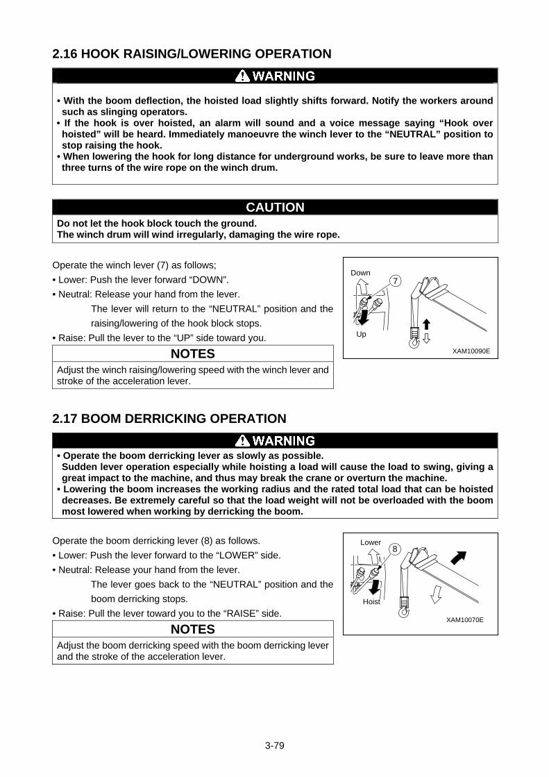
3-79
2.16 HOOK RAISING/LOWERING OPERATION
• With the boom deflection, the hoisted load slightly shifts forward. Notify the workers around such as slinging operators.
• If the hook is over hoisted, an alarm will sound and a voice message saying “Hook over hoisted” will be heard. Immediately manoeuvre the winch lever to the “NEUTRAL” position to stop raising the hook.
• When lowering the hook for long distance for underground works, be sure to leave more than three turns of the wire rope on the winch drum.
CAUTION Do not let the hook block touch the ground. The winch drum will wind irregularly, damaging the wire rope.
Operate the winch lever (7) as follows;
• Lower: Push the lever forward “DOWN”.
• Neutral: Release your hand from the lever.
The lever will return to the “NEUTRAL” position and the
raising/lowering of the hook block stops.
• Raise: Pull the lever to the “UP” side toward you.
NOTES
Adjust the winch raising/lowering speed with the winch lever and stroke of the acceleration lever.
2.17 BOOM DERRICKING OPERATION
• Operate the boom derricking lever as slowly as possible. Sudden lever operation especially while hoisting a load will cause the load to swing, giving a great impact to the machine, and thus may break the crane or overturn the machine.
• Lowering the boom increases the working radius and the rated total load that can be hoisted decreases. Be extremely careful so that the load weight will not be overloaded with the boom most lowered when working by derricking the boom.
Operate the boom derricking lever (8) as follows.
• Lower: Push the lever forward to the “LOWER” side.
• Neutral: Release your hand from the lever.
The lever goes back to the “NEUTRAL” position and the
boom derricking stops.
• Raise: Pull the lever toward you to the “RAISE” side.
NOTES
Adjust the boom derricking speed with the boom derricking lever and the stroke of the acceleration lever.
XAM10090E
Up
Down7
XAM10070E
Hoist
Lower8
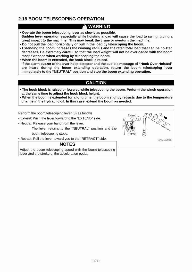
3-80
2.18 BOOM TELESCOPING OPERATION
• Operate the boom telescoping lever as slowly as possible. Sudden lever operation especially while hoisting a load will cause the load to swing, giving a great impact to the machine. This may break the crane or overturn the machine.
• Do not pull the load horizontally or pull in the load by telescoping the boom. • Extending the boom increases the working radius and the rated total load that can be hoisted decreases. Be extremely careful so that the load weight will not be overloaded with the boom most extended when working by telescoping the boom.
• When the boom is extended, the hook block is raised. If the alarm buzzer of the over hoist detector and the audible message of “Hook Over Hoisted” are heard during the boom extending operation, return the boom telecsoping lever immediately to the “NEUTRAL” position and stop the boom extending operation.
CAUTION
• The hook block is raised or lowered while telescoping the boom. Perform the winch operation at the same time to adjust the hook block height.
• When the boom is extended for a long time, the boom slightly retracts due to the temperature change in the hydraulic oil. In this case, extend the boom as needed.
Perform the boom telescoping lever (3) as follows.
• Extend: Push the lever forward to the “EXTEND” side.
• Neutral: Release your hand from the lever.
The lever returns to the “NEUTRAL” position and the
boom telescoping stops.
• Retract: Pull the lever toward you to the “RETRACT” side.
NOTES
Adjust the boom telescoping speed with the boom telescoping lever and the stroke of the acceleration pedal.
Extend
Retract
3
XAM10080E
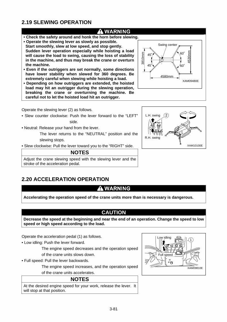
3-81
2.19 SLEWING OPERATION
• Check the safety around and honk the horn before slewing. • Operate the slewing lever as slowly as possible. Start smoothly, slew at low speed, and stop gently. Sudden lever operation especially while hoisting a load will cause the load to swing, causing the loss of stability in the machine, and thus may break the crane or overturn the machine.
• Even if the outriggers are set normally, some directions have lower stability when slewed for 360 degrees. Be extremely careful when slewing while hoisting a load.
• Depending on how outriggers are extended, the hoisted load may hit an outrigger during the slewing operation, breaking the crane or overturning the machine. Be careful not to let the hoisted load hit an outrigger.
Operate the slewing lever (2) as follows.
• Slew counter clockwise: Push the lever forward to the “LEFT”
side.
• Neutral: Release your hand from the lever.
The lever returns to the “NEUTRAL” position and the
slewing stops.
• Slew clockwise: Pull the lever toward you to the “RIGHT” side.
NOTES
Adjust the crane slewing speed with the slewing lever and the stroke of the acceleration pedal.
2.20 ACCELERATION OPERATION
Accelerating the operation speed of the crane units more than is necessary is dangerous.
CAUTION Decrease the speed at the beginning and near the end of an operation. Change the speed to low speed or high speed according to the load.
Operate the acceleration pedal (1) as follows.
• Low idling: Push the lever forward.
The engine speed decreases and the operation speed
of the crane units slows down.
• Full speed: Pull the lever backwards.
The engine speed increases, and the operation speed
of the crane units accelerates.
NOTES
At the desired engine speed for your work, release the lever. It will stop at that position.
L.H. swing
R.H. swing
2
XAM10100E
XAM09810E
Full speed
Low idling1
XAM09480E
4530
mm
3810
mm
4580mm
Swing center
45˚ 60˚
60˚45˚
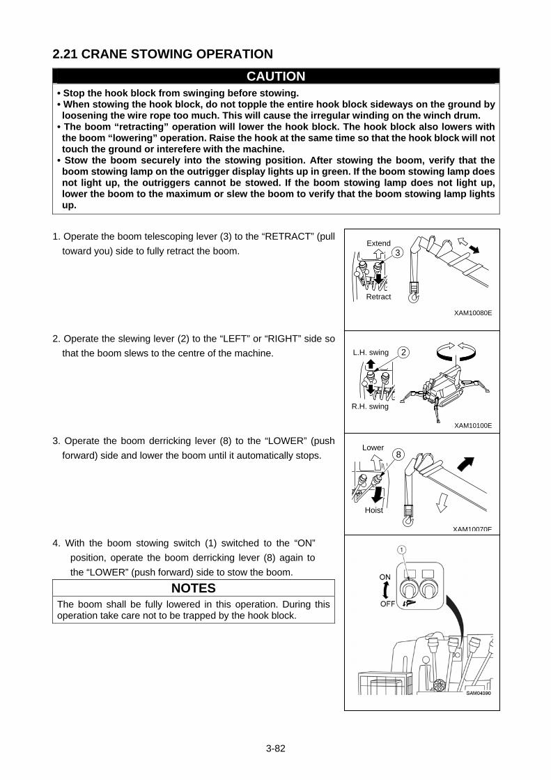
3-82
2.21 CRANE STOWING OPERATION
CAUTION • Stop the hook block from swinging before stowing. • When stowing the hook block, do not topple the entire hook block sideways on the ground by loosening the wire rope too much. This will cause the irregular winding on the winch drum.
• The boom “retracting” operation will lower the hook block. The hook block also lowers with the boom “lowering” operation. Raise the hook at the same time so that the hook block will not touch the ground or interefere with the machine.
• Stow the boom securely into the stowing position. After stowing the boom, verify that the boom stowing lamp on the outrigger display lights up in green. If the boom stowing lamp does not light up, the outriggers cannot be stowed. If the boom stowing lamp does not light up, lower the boom to the maximum or slew the boom to verify that the boom stowing lamp lights up.
1. Operate the boom telescoping lever (3) to the “RETRACT” (pull
toward you) side to fully retract the boom.
2. Operate the slewing lever (2) to the “LEFT” or “RIGHT” side so
that the boom slews to the centre of the machine.
3. Operate the boom derricking lever (8) to the “LOWER” (push
forward) side and lower the boom until it automatically stops.
4. With the boom stowing switch (1) switched to the “ON”
position, operate the boom derricking lever (8) again to
the “LOWER” (push forward) side to stow the boom.
NOTES
The boom shall be fully lowered in this operation. During this operation take care not to be trapped by the hook block.
Extend
Retract
3
XAM10080E
L.H. swing
R.H. swing
2
XAM10100E
XAM10070E
Hoist
Lower8
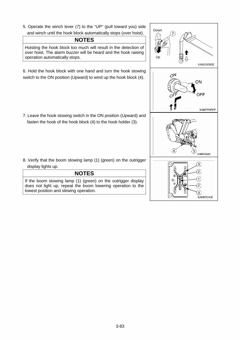
3-83
5. Operate the winch lever (7) to the “UP” (pull toward you) side
and winch until the hook block automatically stops (over hoist).
NOTES
Hoisting the hook block too much will result in the detection of over hoist. The alarm buzzer will be heard and the hook raising operation automatically stops.
6. Hold the hook block with one hand and turn the hook stowing
switch to the ON position (Upward) to wind up the hook block (4).
7. Leave the hook stowing switch in the ON position (Upward) and
fasten the hook of the hook block (4) to the hook holder (3).
8. Verify that the boom stowing lamp (1) (green) on the outrigger
display lights up.
NOTES
If the boom stowing lamp (1) (green) on the outrigger display does not light up, repeat the boom lowering operation to the lowest position and slewing operation.
XAM10090E
Up
Down7
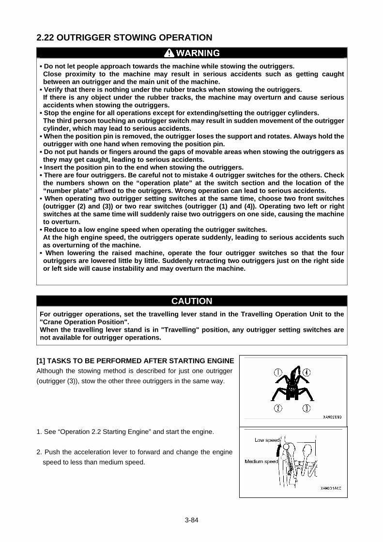
3-84
2.22 OUTRIGGER STOWING OPERATION
• Do not let people approach towards the machine while stowing the outriggers. Close proximity to the machine may result in serious accidents such as getting caught between an outrigger and the main unit of the machine.
• Verify that there is nothing under the rubber tracks when stowing the outriggers. If there is any object under the rubber tracks, the machine may overturn and cause serious accidents when stowing the outriggers.
• Stop the engine for all operations except for extending/setting the outrigger cylinders. The third person touching an outrigger switch may result in sudden movement of the outrigger cylinder, which may lead to serious accidents.
• When the position pin is removed, the outrigger loses the support and rotates. Always hold the outrigger with one hand when removing the position pin.
• Do not put hands or fingers around the gaps of movable areas when stowing the outriggers as they may get caught, leading to serious accidents.
• Insert the position pin to the end when stowing the outriggers. • There are four outriggers. Be careful not to mistake 4 outrigger switches for the others. Check the numbers shown on the “operation plate” at the switch section and the location of the “number plate” affixed to the outriggers. Wrong operation can lead to serious accidents.
• When operating two outrigger setting switches at the same time, choose two front switches (outrigger (2) and (3)) or two rear switches (outrigger (1) and (4)). Operating two left or right switches at the same time will suddenly raise two outriggers on one side, causing the machine to overturn.
• Reduce to a low engine speed when operating the outrigger switches. At the high engine speed, the outriggers operate suddenly, leading to serious accidents such as overturning of the machine.
• When lowering the raised machine, operate the four outrigger switches so that the four outriggers are lowered little by little. Suddenly retracting two outriggers just on the right side or left side will cause instability and may overturn the machine.
CAUTION For outrigger operations, set the travelling lever stand in the Travelling Operation Unit to the "Crane Operation Position". When the travelling lever stand is in "Travelling" position, any outrigger setting switches are not available for outrigger operations.
[1] TASKS TO BE PERFORMED AFTER STARTING ENGINE
Although the stowing method is described for just one outrigger
(outrigger (3)), stow the other three outriggers in the same way.
1. See “Operation 2.2 Starting Engine” and start the engine.
2. Push the acceleration lever to forward and change the engine
speed to less than medium speed.
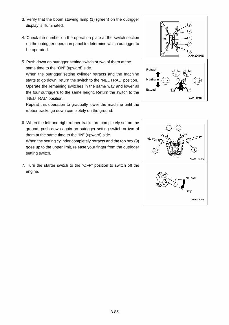
3-85
3. Verify that the boom stowing lamp (1) (green) on the outrigger
display is illuminated.
4. Check the number on the operation plate at the switch section
on the outrigger operation panel to determine which outrigger to
be operated.
5. Push down an outrigger setting switch or two of them at the
same time to the “ON” (upward) side.
When the outrigger setting cylinder retracts and the machine
starts to go down, return the switch to the “NEUTRAL” position.
Operate the remaining switches in the same way and lower all
the four outriggers to the same height. Return the switch to the
“NEUTRAL” position.
Repeat this operation to gradually lower the machine until the
rubber tracks go down completely on the ground.
6. When the left and right rubber tracks are completely set on the
ground, push down again an outrigger setting switch or two of
them at the same time to the “IN” (upward) side.
When the setting cylinder completely retracts and the top box (9)
goes up to the upper limit, release your finger from the outrigger
setting switch.
7. Turn the starter switch to the “OFF” position to switch off the
engine.
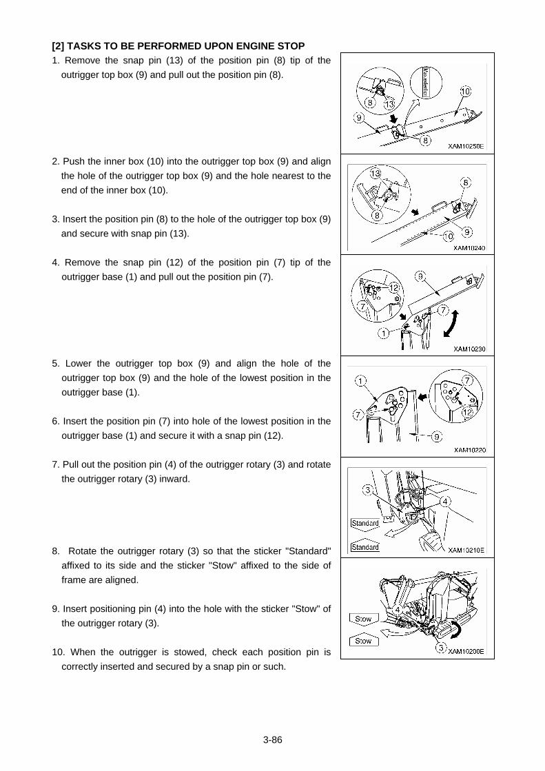
3-86
[2] TASKS TO BE PERFORMED UPON ENGINE STOP
1. Remove the snap pin (13) of the position pin (8) tip of the
outrigger top box (9) and pull out the position pin (8).
2. Push the inner box (10) into the outrigger top box (9) and align
the hole of the outrigger top box (9) and the hole nearest to the
end of the inner box (10).
3. Insert the position pin (8) to the hole of the outrigger top box (9)
and secure with snap pin (13).
4. Remove the snap pin (12) of the position pin (7) tip of the
outrigger base (1) and pull out the position pin (7).
5. Lower the outrigger top box (9) and align the hole of the
outrigger top box (9) and the hole of the lowest position in the
outrigger base (1).
6. Insert the position pin (7) into hole of the lowest position in the
outrigger base (1) and secure it with a snap pin (12).
7. Pull out the position pin (4) of the outrigger rotary (3) and rotate
the outrigger rotary (3) inward.
8. Rotate the outrigger rotary (3) so that the sticker "Standard"
affixed to its side and the sticker "Stow" affixed to the side of
frame are aligned.
9. Insert positioning pin (4) into the hole with the sticker "Stow" of
the outrigger rotary (3).
10. When the outrigger is stowed, check each position pin is
correctly inserted and secured by a snap pin or such.
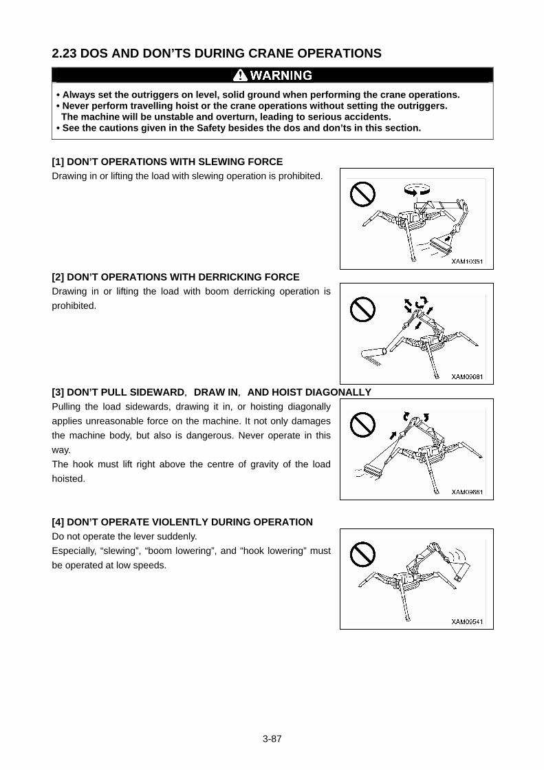
3-87
2.23 DOS AND DON’TS DURING CRANE OPERATIONS
• Always set the outriggers on level, solid ground when performing the crane operations. • Never perform travelling hoist or the crane operations without setting the outriggers. The machine will be unstable and overturn, leading to serious accidents.
• See the cautions given in the Safety besides the dos and don’ts in this section.
[1] DON’T OPERATIONS WITH SLEWING FORCE
Drawing in or lifting the load with slewing operation is prohibited.
[2] DON’T OPERATIONS WITH DERRICKING FORCE
Drawing in or lifting the load with boom derricking operation is
prohibited.
[3] DON’T PULL SIDEWARD, DRAW IN, AND HOIST DIAGONALLY
Pulling the load sidewards, drawing it in, or hoisting diagonally
applies unreasonable force on the machine. It not only damages
the machine body, but also is dangerous. Never operate in this
way.
The hook must lift right above the centre of gravity of the load
hoisted.
[4] DON’T OPERATE VIOLENTLY DURING OPERATION
Do not operate the lever suddenly.
Especially, “slewing”, “boom lowering”, and “hook lowering” must
be operated at low speeds.
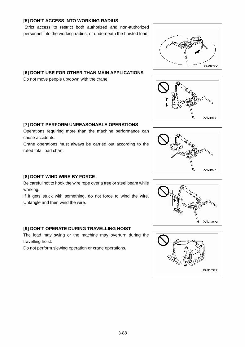
3-88
[5] DON’T ACCESS INTO WORKING RADIUS
Strict access to restrict both authorized and non-authorized
personnel into the working radius, or underneath the hoisted load.
[6] DON’T USE FOR OTHER THAN MAIN APPLICATIONS
Do not move people up/down with the crane.
[7] DON’T PERFORM UNREASONABLE OPERATIONS
Operations requiring more than the machine performance can
cause accidents.
Crane operations must always be carried out according to the
rated total load chart.
[8] DON’T WIND WIRE BY FORCE
Be careful not to hook the wire rope over a tree or steel beam while
working.
If it gets stuck with something, do not force to wind the wire.
Untangle and then wind the wire.
[9] DON’T OPERATE DURING TRAVELLING HOIST
The load may swing or the machine may overturn during the
travelling hoist.
Do not perform slewing operation or crane operations.
3-89
3. HANDLING RUBBER TRACKS
3.1 GOOD USE
While the rubber tracks demonstrate many advantages thanks to its performance characteristic to the
material, it has a weak point in strength.
Therefore, we would like you to sufficiently understand the characteristics of the rubber tracks and to
respect don’ts operations and observe the cautions on handling so that the life of the rubber tracks can be
extended and its advantages exercised.
Be sure to read “3.3 Dos and Don’ts with Rubber Tracks” and “3.4 Cautions in Using Rubber Tracks” in the
Operation before using the machine.
3.2 WARRANTY
Verification of proper tension of the rubber tracks, maintenance of rubber tracks, and damage caused by
the fault of customers such as not respecting don’ts operation or not observing cautions in working, for
example, “worked at the site where there were objects that may tear the rubber blocks, such as steel
plates, U-shaped gutters, corners of bricks, corners of sheer broken stones and rocks, reinforcing steels,
and iron scraps”, are not covered by warranty.
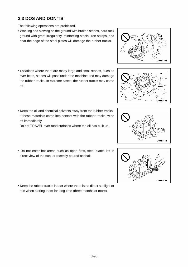
3-90
3.3 DOS AND DON’TS
The following operations are prohibited.
• Working and slewing on the ground with broken stones, hard rock
ground with great irregularity, reinforcing steels, iron scraps, and
near the edge of the steel plates will damage the rubber tracks.
• Locations where there are many large and small stones, such as
river beds, stones will pass under the machine and may damage
the rubber tracks. In extreme cases, the rubber tracks may come
off.
• Keep the oil and chemical solvents away from the rubber tracks.
If these materials come into contact with the rubber tracks, wipe
off immediately.
Do not TRAVEL over road surfaces where the oil has built up.
• Do not enter hot areas such as open fires, steel plates left in
direct view of the sun, or recently poured asphalt.
• Keep the rubber tracks indoor where there is no direct sunlight or
rain when storing them for long time (three months or more).
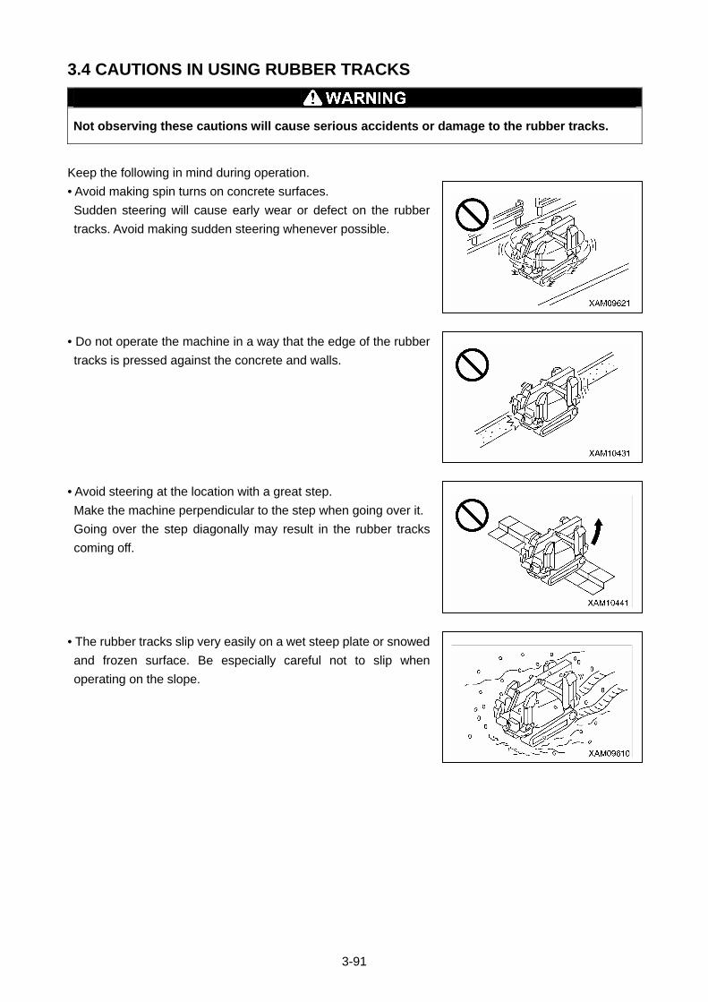
3-91
3.4 CAUTIONS IN USING RUBBER TRACKS
Not observing these cautions will cause serious accidents or damage to the rubber tracks.
Keep the following in mind during operation.
• Avoid making spin turns on concrete surfaces.
Sudden steering will cause early wear or defect on the rubber
tracks. Avoid making sudden steering whenever possible.
• Do not operate the machine in a way that the edge of the rubber
tracks is pressed against the concrete and walls.
• Avoid steering at the location with a great step.
Make the machine perpendicular to the step when going over it.
Going over the step diagonally may result in the rubber tracks
coming off.
• The rubber tracks slip very easily on a wet steep plate or snowed
and frozen surface. Be especially careful not to slip when
operating on the slope.
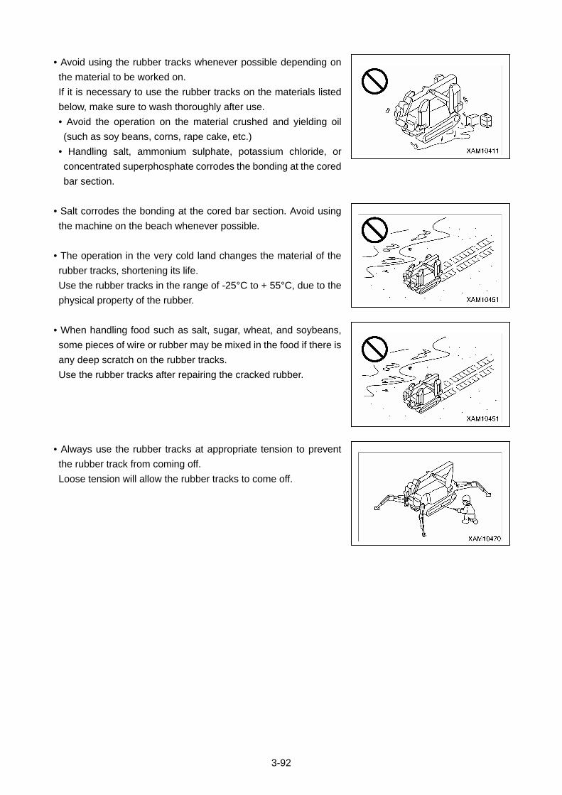
3-92
• Avoid using the rubber tracks whenever possible depending on
the material to be worked on.
If it is necessary to use the rubber tracks on the materials listed
below, make sure to wash thoroughly after use.
• Avoid the operation on the material crushed and yielding oil
(such as soy beans, corns, rape cake, etc.)
• Handling salt, ammonium sulphate, potassium chloride, or
concentrated superphosphate corrodes the bonding at the cored
bar section.
• Salt corrodes the bonding at the cored bar section. Avoid using
the machine on the beach whenever possible.
• The operation in the very cold land changes the material of the
rubber tracks, shortening its life.
Use the rubber tracks in the range of -25°C to + 55°C, due to the
physical property of the rubber.
• When handling food such as salt, sugar, wheat, and soybeans,
some pieces of wire or rubber may be mixed in the food if there is
any deep scratch on the rubber tracks.
Use the rubber tracks after repairing the cracked rubber.
• Always use the rubber tracks at appropriate tension to prevent
the rubber track from coming off.
Loose tension will allow the rubber tracks to come off.
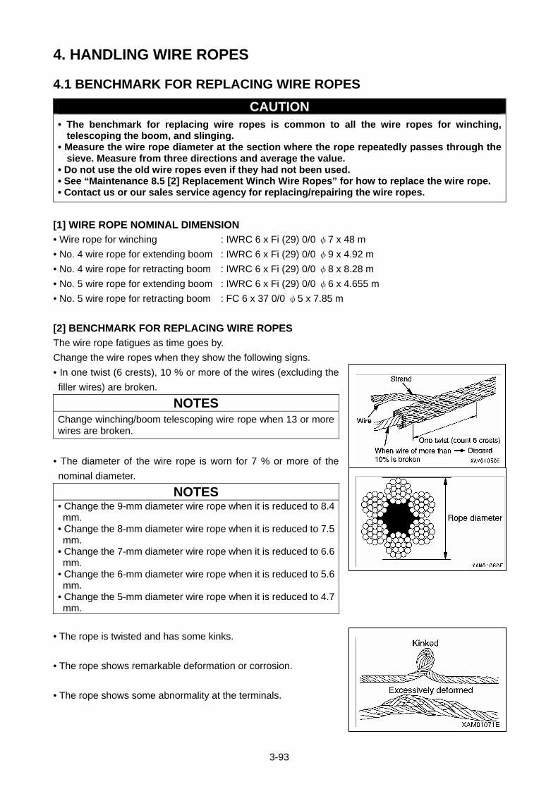
3-93
4. HANDLING WIRE ROPES
4.1 BENCHMARK FOR REPLACING WIRE ROPES
CAUTION • The benchmark for replacing wire ropes is common to all the wire ropes for winching,
telescoping the boom, and slinging. • Measure the wire rope diameter at the section where the rope repeatedly passes through the
sieve. Measure from three directions and average the value. • Do not use the old wire ropes even if they had not been used. • See “Maintenance 8.5 [2] Replacement Winch Wire Ropes” for how to replace the wire rope. • Contact us or our sales service agency for replacing/repairing the wire ropes.
[1] WIRE ROPE NOMINAL DIMENSION
• Wire rope for winching : IWRC 6 x Fi (29) 0/0 φ7 x 48 m
• No. 4 wire rope for extending boom : IWRC 6 x Fi (29) 0/0 φ9 x 4.92 m
• No. 4 wire rope for retracting boom : IWRC 6 x Fi (29) 0/0 φ8 x 8.28 m
• No. 5 wire rope for extending boom : IWRC 6 x Fi (29) 0/0 φ6 x 4.655 m
• No. 5 wire rope for retracting boom : FC 6 x 37 0/0 φ5 x 7.85 m
[2] BENCHMARK FOR REPLACING WIRE ROPES
The wire rope fatigues as time goes by.
Change the wire ropes when they show the following signs.
• In one twist (6 crests), 10 % or more of the wires (excluding the
filler wires) are broken.
NOTES
Change winching/boom telescoping wire rope when 13 or more wires are broken.
• The diameter of the wire rope is worn for 7 % or more of the
nominal diameter.
NOTES • Change the 9-mm diameter wire rope when it is reduced to 8.4 mm.
• Change the 8-mm diameter wire rope when it is reduced to 7.5 mm.
• Change the 7-mm diameter wire rope when it is reduced to 6.6 mm.
• Change the 6-mm diameter wire rope when it is reduced to 5.6 mm.
• Change the 5-mm diameter wire rope when it is reduced to 4.7 mm.
• The rope is twisted and has some kinks.
• The rope shows remarkable deformation or corrosion.
• The rope shows some abnormality at the terminals.
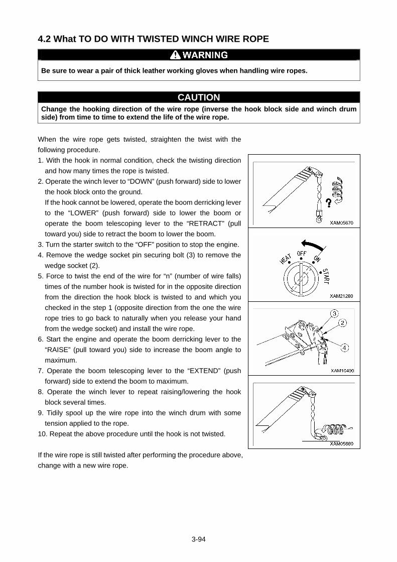
3-94
4.2 What TO DO WITH TWISTED WINCH WIRE ROPE
Be sure to wear a pair of thick leather working gloves when handling wire ropes.
CAUTION Change the hooking direction of the wire rope (inverse the hook block side and winch drum side) from time to time to extend the life of the wire rope.
When the wire rope gets twisted, straighten the twist with the
following procedure.
1. With the hook in normal condition, check the twisting direction
and how many times the rope is twisted.
2. Operate the winch lever to “DOWN” (push forward) side to lower
the hook block onto the ground.
If the hook cannot be lowered, operate the boom derricking lever
to the “LOWER” (push forward) side to lower the boom or
operate the boom telescoping lever to the “RETRACT” (pull
toward you) side to retract the boom to lower the boom.
3. Turn the starter switch to the “OFF” position to stop the engine.
4. Remove the wedge socket pin securing bolt (3) to remove the
wedge socket (2).
5. Force to twist the end of the wire for “n” (number of wire falls)
times of the number hook is twisted for in the opposite direction
from the direction the hook block is twisted to and which you
checked in the step 1 (opposite direction from the one the wire
rope tries to go back to naturally when you release your hand
from the wedge socket) and install the wire rope.
6. Start the engine and operate the boom derricking lever to the
“RAISE” (pull toward you) side to increase the boom angle to
maximum.
7. Operate the boom telescoping lever to the “EXTEND” (push
forward) side to extend the boom to maximum.
8. Operate the winch lever to repeat raising/lowering the hook
block several times.
9. Tidily spool up the wire rope into the winch drum with some
tension applied to the rope.
10. Repeat the above procedure until the hook is not twisted.
If the wire rope is still twisted after performing the procedure above,
change with a new wire rope.
3-95
5. TRANSPORTATION Observe the related laws and regulations and transport the machine safely.
5.1 LOADING/UNLOADING
• See "Specifications 1.1 Specification List” in the Dimension for the dimensions and mass of the machine.
• Select and use the ramp boards that satisfy the following conditions. • Has a length that when placed, the angle from the track is 15 degrees or less. • Has a width no narrower than the rubber tracks. • Has a thickness and strength that can fully withstand the mass of the machine.
• Be sure to place the ramp boards perpendicular to the truck box. Also, match the centre of the each of the rubber tracks with the centre of corresponding ramp board. Misguided ramp boards and unmatched rubber crawlers may cause the machine to slip out of the ramp boards and cause serious accidents.
• Use ramp boards with slope of 15 degrees or less. The space between boards shall be set to be appropriate to the centre of the rubber tracks.
• Always put the machine in the “travelling posture” when loading/unloading the machine. See “Operation 2.5 Machine Travelling Posture” for travelling posture.
• Always load the machine by moving backward. Moving forward involves overturning hazard. The operator must be on the back side of the truck.
• Always unload the machine by moving forward. Moving backward involves overturning hazard. The operator must be on the back side of the truck.
• Loading/Unloading the machine involves danger. Be extremely careful.
• Select flat and solid ground for loading/unloading the machine. Keep sufficient distance from the shoulders.
• Remove dirt around the crawlers to prevent side slip of the machine on the ramp boards. Remove any materials on the loading ramps such as ice, grease, and oil.
• Never change direction on the ramp boards. Go down from the ramp board, and then change the direction.
Always put the machine in the “travelling posture” when
loading/unloading the machine. Always use ramp boards or
forwarding blocks when loading/unloading the machine and use
the following procedure.
1. Brake the trailer securely. Place wheel blocks next to the wheels of the trailer to secure the trailer.
2. Ramp boards must be suitably aligned so that the machine rests
in the centre of the trailer.
NOTES
Verify that the two ramp boards are at the same height.
3. Operate the acceleration pedal and keep the engine at low speed.
4. TRAVEL slowly toward the ramp boards, and load/unload the machine in a way that the boom does not
hit the trailer. Move backward to load the machine, and forward to unload the machine.
5. Do not operate any other lever than travelling levers on the ramp boards.
6. Load the machine properly to the desired position on the trailer.
3-96
5.2 HOISTING MACHINE
• When lifting up the Machine, always set it to the stowage position first, and lift from the lifting bracket (A) on the top of the boom. Only use this bracket and only one sling wire. Any other manner than this, i.e. from other lifting brackets or multiple sling wires, may cause droppage of the machine and result in a serious injury or death. Where there is no choice but to hoist in a different manner, please contact us or service agencies.
• The hoisting attachments such as wire ropes and shackles used in hoisting should be sufficiently strong enough for the weight of this machine.
• Crane stowed position when it is hoisted means its “Travelling position” where 4 of outrigger position pins are securely inserted in the outrigger rotary. The centre of the balance of the machine is specified subject to the machine being in its travelling position. In addition, to set it into that position correctly, secure the hook block (4) to its stowing position, also tension the wire rope tight, this will prevent the boom derricking cylinder form extending. Refer to "Operation 2.5 Machine Travelling Position" for details of travelling position.
• Hoisting the machine for a long time will cause the boom derricking cylinder to extend, shifting the centre of gravity and the machine to lose balance. Hoisting should be limited to a max of 10 minutes.
• Where it is required to hoist the machine for a longer time (exceeding 10 minutes), or when it is carried by a helicopter, use a proper carriage deck as shown in the diagram on the right, for safe transportation.
CAUTION • When the local laws and regulations are applicable, the person who uses the crane to perform hoisting operation must be qualified to do so. If not, the operator must be well trained and skilled.
• See the Dimension or the nameplate attached to the machine for the weight of the machine.
• The dimensions are for standard specifications. The hoisting method varies depending on the attachments and options mounted. In that case, contact us or our sales service agency.
3-97
Hoist the machine on solid and flat ground using the following
procedure.
1. See “Operation 2.5 Machine Travelling Position” and put the
machine in the “Travelling position”.
2. Verify that the position pins (four) are securely inserted in the
outrigger rotary joint of the 4 outriggers.
3. Hang the hook (2) directly to the bracket (A) on the top of the
boom, or use a shackle (1) to hang the hook (2).
NOTES
Position (A) on the top of the boom is in the centre of gravity of the machine.
4. As soon as the machine leaves the ground, stop and wait until
the machine is stabilized. Then slowly hoist the machine.
5. Check the changes in the position due to the leakage from the
hydraulic circuit on the head side of the derricking cylinder (4)
when the machine is hoisted.
5.3 CAUTIONS IN LOADING MACHINE
Select flat and solid ground for loading/unloading the machine. Keep sufficient distance from the shoulders.
Load the machine to the specified position on the trailer and secure
the machine with the following procedure.
1. Stop the engine and remove the key of the starter switch.
2. Place a square piece of timber in the front and back of the
rubber tracks to prevent the machine from moving during
transportation. Secure the machine with chain or wire rope, and
do not let it move from side to side.
5.4 CAUTIONS DURING TRANSPORTATION
Take road width, height, and weight into consideration in determining the transportation route.
If there are applicable local laws and regulations, observe these laws and regulations for safe
transportation.
If not, contact us or our sales service agency.
3-98
6. HANDLING IN COLD WEATHER
6.1 PREPARING FOR LOW TEMPERATURE
In cold conditions, the machine starts to have some difficulty in starting. Take the following actions.
[1] LUBRICATION
Change the oil to the one with low viscosity. See “Maintenance 5.1 Use of Lubricating Oil According to
Temperature” for the specified viscosity.
[2] COOLING WATER
Antifreezing fluid is inflammable. Do not put the fluid close to fire and do not smoke while handling the fluid.
CAUTION
Never use antifreezing fluid with methanol, ethanol, and propanol.
See “Maintenance 8.11 Maintenance Every 1000 Hours [2] Cleaning Engine Cooling System” for the
cooling water replacement period and mixing rate of antifreezing fluid.
[3] BATTERY
• The battery produces combustible gas and can be explosive. Do not put fire close to the battery.
• The battery fluid is a harmful substance. Keep it away from your eyes and skin. Should it come into contact with your eye or skin, wash the affected area with plenty of water and consult a physician immediately.
The battery capacity drops when the temperature decreases.
In this condition, the battery fluid can freeze with low battery charging rate. Keep the charging rate as
close to as 100 %. Keep the battery warm in order to start the engine next morning.
NOTES
Measure the specific gravity of the battery fluid and convert it into the charging rate using the chart below.
Fluid Temperature (°C)
20 0 -10 -20
100 1.28 1.29 1.30 1.31
90 1.26 1.27 1.28 1.29
80 1.24 1.25 1.26 1.27 Charging Rate (%)
75 1.23 1.24 1.25 1.26
3-99
[4] CAUTIONS AFTER COMPLETING THE OPERATION
Observe the followings to prevent the machine from not being able to function the next morning because
of deposits such as dirt and water and materials around the feet frozen.
• Remove dirt and water on the machine.
Keep the hydraulic cylinder rod surface especially clean to prevent seal from being damaged with the dirt
coming into the seal together with the water drops.
• Park the machine on solid and dry ground.
If there is no such location to park, place a board on the ground to park the machine on the board.
This prevents the ground and around the feet of the machine from freezing and allows the machine to
start moving next morning.
• Remove the drain plug to drain the water in the fuel system to prevent the water from freezing.
• The battery ability remarkably drops at low temperature.
Cover the battery or remove the battery from the machine and keep it in a warm place to be installed next
morning.
• If the electrolyte level is low, refill with distilled water next morning before starting the operation.
Do not refill after the operation in order to prevent the water from freezing during the night.
• Remove any snow and ice on the machine. Particularly, remove snow and
ice on the boom completely, because they may fall during operation.
• Check that the load is not frozen to the ground. It is dangerous to lift a load
being stuck to the ground during night.
[5] AFTER THE COLD WEATHER IS GONE
When the season changed and it started to get warm, take the following action.
• See “Maintenance 5.1 Use of Lubricating Oil According to Temperature” to change the oil in the system
to the one with specified viscosity.
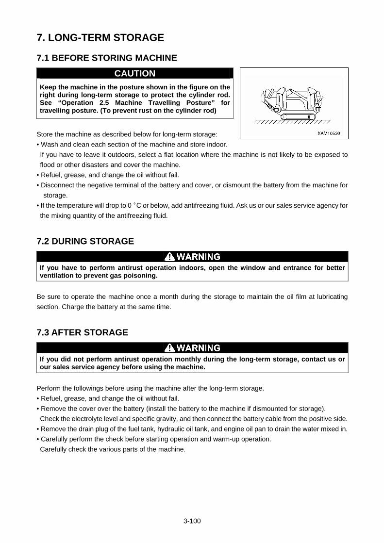
3-100
7. LONG-TERM STORAGE
7.1 BEFORE STORING MACHINE
CAUTION
Keep the machine in the posture shown in the figure on the right during long-term storage to protect the cylinder rod. See “Operation 2.5 Machine Travelling Posture” for travelling posture. (To prevent rust on the cylinder rod)
Store the machine as described below for long-term storage:
• Wash and clean each section of the machine and store indoor.
If you have to leave it outdoors, select a flat location where the machine is not likely to be exposed to
flood or other disasters and cover the machine.
• Refuel, grease, and change the oil without fail.
• Disconnect the negative terminal of the battery and cover, or dismount the battery from the machine for
storage.
• If the temperature will drop to 0 ºC or below, add antifreezing fluid. Ask us or our sales service agency for
the mixing quantity of the antifreezing fluid.
7.2 DURING STORAGE
If you have to perform antirust operation indoors, open the window and entrance for better ventilation to prevent gas poisoning.
Be sure to operate the machine once a month during the storage to maintain the oil film at lubricating
section. Charge the battery at the same time.
7.3 AFTER STORAGE
If you did not perform antirust operation monthly during the long-term storage, contact us or our sales service agency before using the machine.
Perform the followings before using the machine after the long-term storage.
• Refuel, grease, and change the oil without fail.
• Remove the cover over the battery (install the battery to the machine if dismounted for storage).
Check the electrolyte level and specific gravity, and then connect the battery cable from the positive side.
• Remove the drain plug of the fuel tank, hydraulic oil tank, and engine oil pan to drain the water mixed in.
• Carefully perform the check before starting operation and warm-up operation.
Carefully check the various parts of the machine.
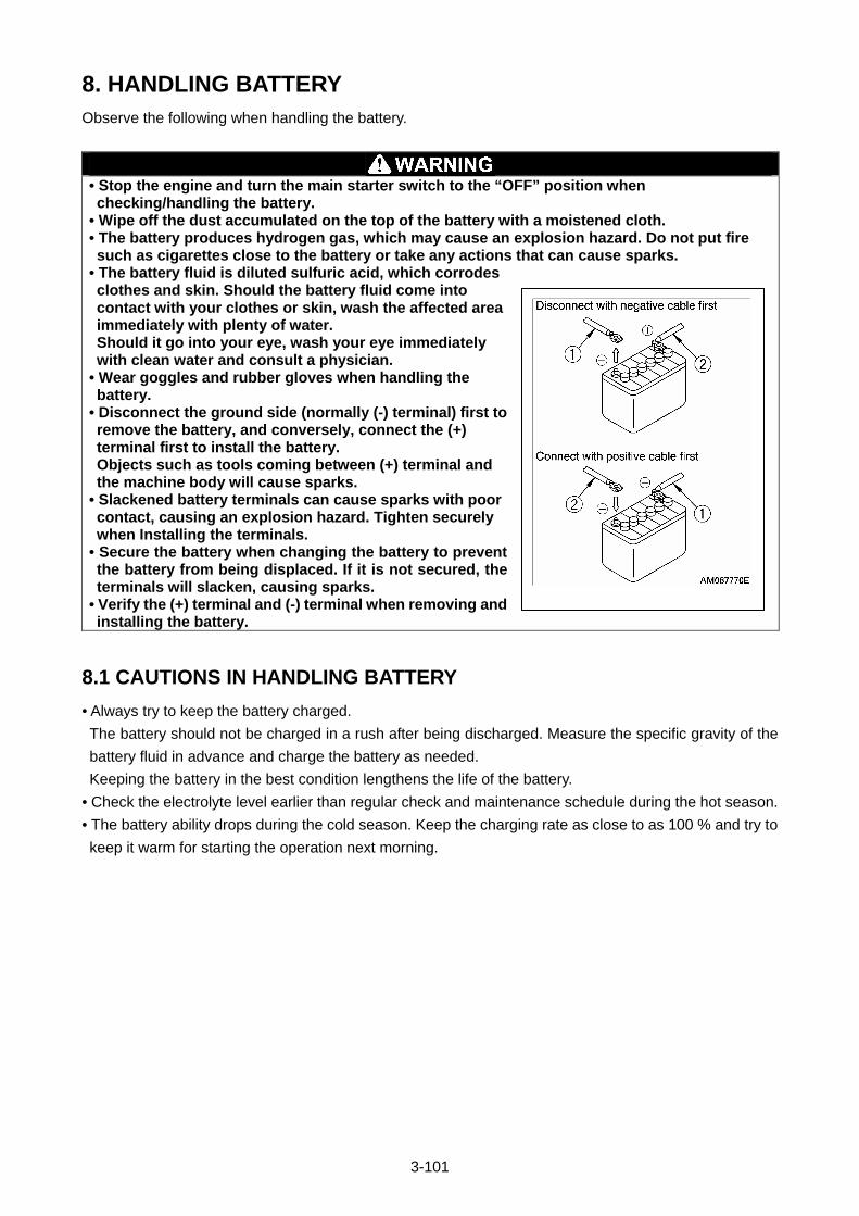
3-101
8. HANDLING BATTERY Observe the following when handling the battery.
• Stop the engine and turn the main starter switch to the “OFF” position when checking/handling the battery.
• Wipe off the dust accumulated on the top of the battery with a moistened cloth. • The battery produces hydrogen gas, which may cause an explosion hazard. Do not put fire such as cigarettes close to the battery or take any actions that can cause sparks.
• The battery fluid is diluted sulfuric acid, which corrodes clothes and skin. Should the battery fluid come into contact with your clothes or skin, wash the affected area immediately with plenty of water. Should it go into your eye, wash your eye immediately with clean water and consult a physician.
• Wear goggles and rubber gloves when handling the battery.
• Disconnect the ground side (normally (-) terminal) first to remove the battery, and conversely, connect the (+) terminal first to install the battery. Objects such as tools coming between (+) terminal and the machine body will cause sparks.
• Slackened battery terminals can cause sparks with poor contact, causing an explosion hazard. Tighten securely when Installing the terminals.
• Secure the battery when changing the battery to prevent the battery from being displaced. If it is not secured, the terminals will slacken, causing sparks.
• Verify the (+) terminal and (-) terminal when removing and installing the battery.
8.1 CAUTIONS IN HANDLING BATTERY
• Always try to keep the battery charged.
The battery should not be charged in a rush after being discharged. Measure the specific gravity of the
battery fluid in advance and charge the battery as needed.
Keeping the battery in the best condition lengthens the life of the battery.
• Check the electrolyte level earlier than regular check and maintenance schedule during the hot season.
• The battery ability drops during the cold season. Keep the charging rate as close to as 100 % and try to
keep it warm for starting the operation next morning.

3-102
8.2 REMOVING/INSTALLING BATTERY
CAUTION
Verify that the battery does not move after securing the battery. If it moves, secure it again.
[1] REMOVAL
1. See “Operation 1.6 Machinery cover” and remove the machinery cover.
2. Disconnect the (-) terminal (5) on the ground side first and then
the (+) terminal (6) to disconnect the battery cable.
3. Remove the wing nut (4), battery fixing brackets (3), and then
remove the battery (5).
[2] INSTALLATION
• Reverse the removal procedure to install the battery.
NOTES
Connect the (-) terminal (1) on the ground side last when connecting the battery.

3-103
8.3 CAUTIONS IN CHARGING BATTERY
When charging the battery mounted to the machine
• Abnormal voltage may be applied to the alternator, resulting in a breakage. Disconnect the battery
terminal wires before charging the battery.
• Remove all the fluid plugs to release the gas generated.
• Stop charging when the battery becomes overheated (fluid temperature exceeded 45 °C).
• Stop charging promptly once the charging is completed.
Charging even after the charging is completed will;
(1) overheat the battery
(2) reduce the electrolyte level
(3) cause failures in battery
• Never inverse the connection of [(+) terminal and (-) terminal]. Doing so can cause damage on alternator.
• Remove the battery cable when handling the battery other than for battery electrolyte level check and
specific gravity measurement.
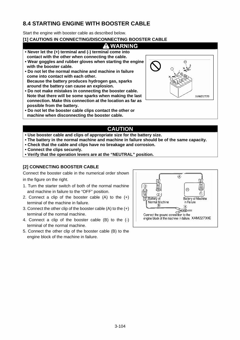
3-104
8.4 STARTING ENGINE WITH BOOSTER CABLE
Start the engine with booster cable as described below.
[1] CAUTIONS IN CONNECTING/DISCONNECTING BOOSTER CABLE
• Never let the (+) terminal and (-) terminal come into contact with the other when connecting the cable.
• Wear goggles and rubber gloves when starting the engine with the booster cable.
• Do not let the normal machine and machine in failure come into contact with each other. Because the battery produces hydrogen gas, sparks around the battery can cause an explosion.
• Do not make mistakes in connecting the booster cable. Note that there will be some sparks when making the last connection. Make this connection at the location as far as possible from the battery.
• Do not let the booster cable clips contact the other or machine when disconnecting the booster cable.
CAUTION • Use booster cable and clips of appropriate size for the battery size. • The battery in the normal machine and machine in failure should be of the same capacity. • Check that the cable and clips have no breakage and corrosion. • Connect the clips securely. • Verify that the operation levers are at the “NEUTRAL” position.
[2] CONNECTING BOOSTER CABLE
Connect the booster cable in the numerical order shown
in the figure on the right.
1. Turn the starter switch of both of the normal machine and machine in failure to the “OFF” position.
2. Connect a clip of the booster cable (A) to the (+) terminal of the machine in failure.
3. Connect the other clip of the booster cable (A) to the (+) terminal of the normal machine.
4. Connect a clip of the booster cable (B) to the (-) terminal of the normal machine.
5. Connect the other clip of the booster cable (B) to the engine block of the machine in failure.
3-105
[3] STARTING ENGINE
Verify that the operation levers are at the “NEUTRAL” position. If the safety lock lever is equipped, also verify that the safety lock lever is at the lock position.
1. Verify that the clips are securely connected to the battery terminals. 2. Start the engine of the normal machine and increase the engine speed to full speed (highest speed). 3. Turn the starter switch of the machine in failure to the “START” position to start the engine.
If the engine does not start, wait for more than 2 minutes before re-starting.
NOTES
See “Operation 2.2 Starting Engine” for how to start the engine.
[4] DISCONNECTING BOOSTER CABLE
When the engine started, disconnect the booster cable in
the reverse order of connecting the booster cable.
1. Disconnect the clip of the booster cable (B) connected to the engine block of the machine in failure.
2. Disconnect the clip of the booster cable (B) connected to the (-) terminal of the normal machine.
3. Disconnect the clip of the booster cable (A) connected to the (+) terminal of the normal machine.
4. Disconnect the clip of the booster cable (A) connected to the (+) terminal of the machine in failure.
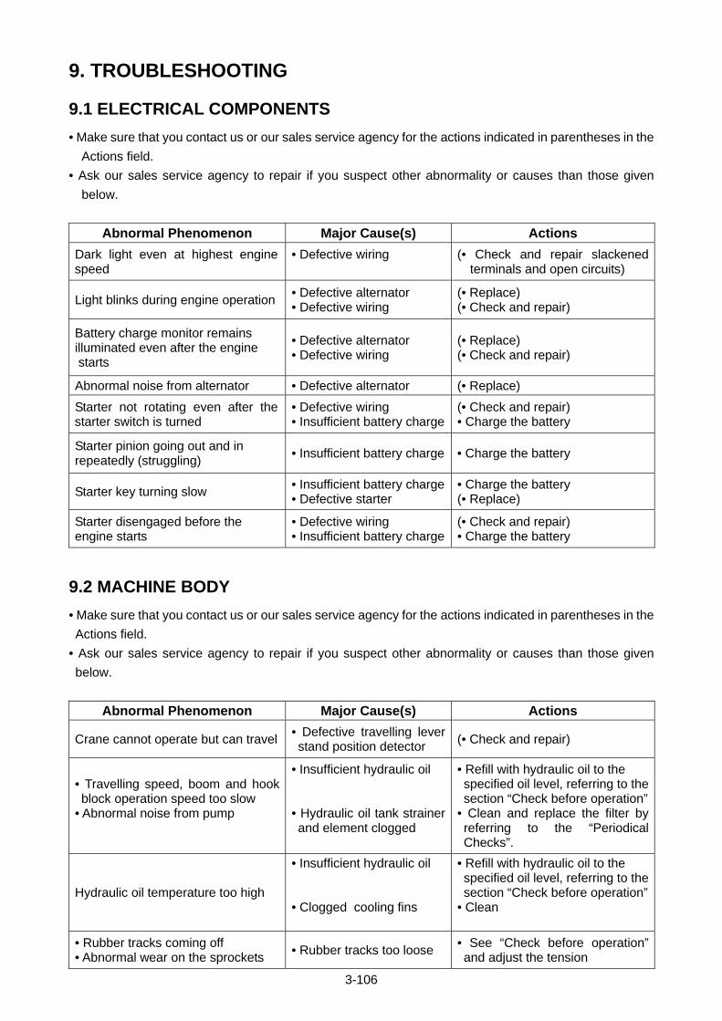
3-106
9. TROUBLESHOOTING
9.1 ELECTRICAL COMPONENTS
• Make sure that you contact us or our sales service agency for the actions indicated in parentheses in the
Actions field.
• Ask our sales service agency to repair if you suspect other abnormality or causes than those given
below.
Abnormal Phenomenon Major Cause(s) Actions
Dark light even at highest engine speed
• Defective wiring
(• Check and repair slackened terminals and open circuits)
Light blinks during engine operation • Defective alternator • Defective wiring
(• Replace) (• Check and repair)
Battery charge monitor remains illuminated even after the engine starts
• Defective alternator • Defective wiring
(• Replace) (• Check and repair)
Abnormal noise from alternator • Defective alternator (• Replace)
Starter not rotating even after the starter switch is turned
• Defective wiring • Insufficient battery charge
(• Check and repair) • Charge the battery
Starter pinion going out and in repeatedly (struggling)
• Insufficient battery charge • Charge the battery
Starter key turning slow • Insufficient battery charge• Defective starter
• Charge the battery (• Replace)
Starter disengaged before the engine starts
• Defective wiring • Insufficient battery charge
(• Check and repair) • Charge the battery
9.2 MACHINE BODY
• Make sure that you contact us or our sales service agency for the actions indicated in parentheses in the
Actions field.
• Ask our sales service agency to repair if you suspect other abnormality or causes than those given
below.
Abnormal Phenomenon Major Cause(s) Actions
Crane cannot operate but can travel • Defective travelling lever stand position detector
(• Check and repair)
• Travelling speed, boom and hook block operation speed too slow
• Abnormal noise from pump
• Insufficient hydraulic oil • Hydraulic oil tank strainer and element clogged
• Refill with hydraulic oil to the specified oil level, referring to the section “Check before operation”
• Clean and replace the filter by referring to the “Periodical Checks”.
Hydraulic oil temperature too high
• Insufficient hydraulic oil • Clogged cooling fins
• Refill with hydraulic oil to the specified oil level, referring to the section “Check before operation”
• Clean
• Rubber tracks coming off • Abnormal wear on the sprockets
• Rubber tracks too loose • See “Check before operation” and adjust the tension
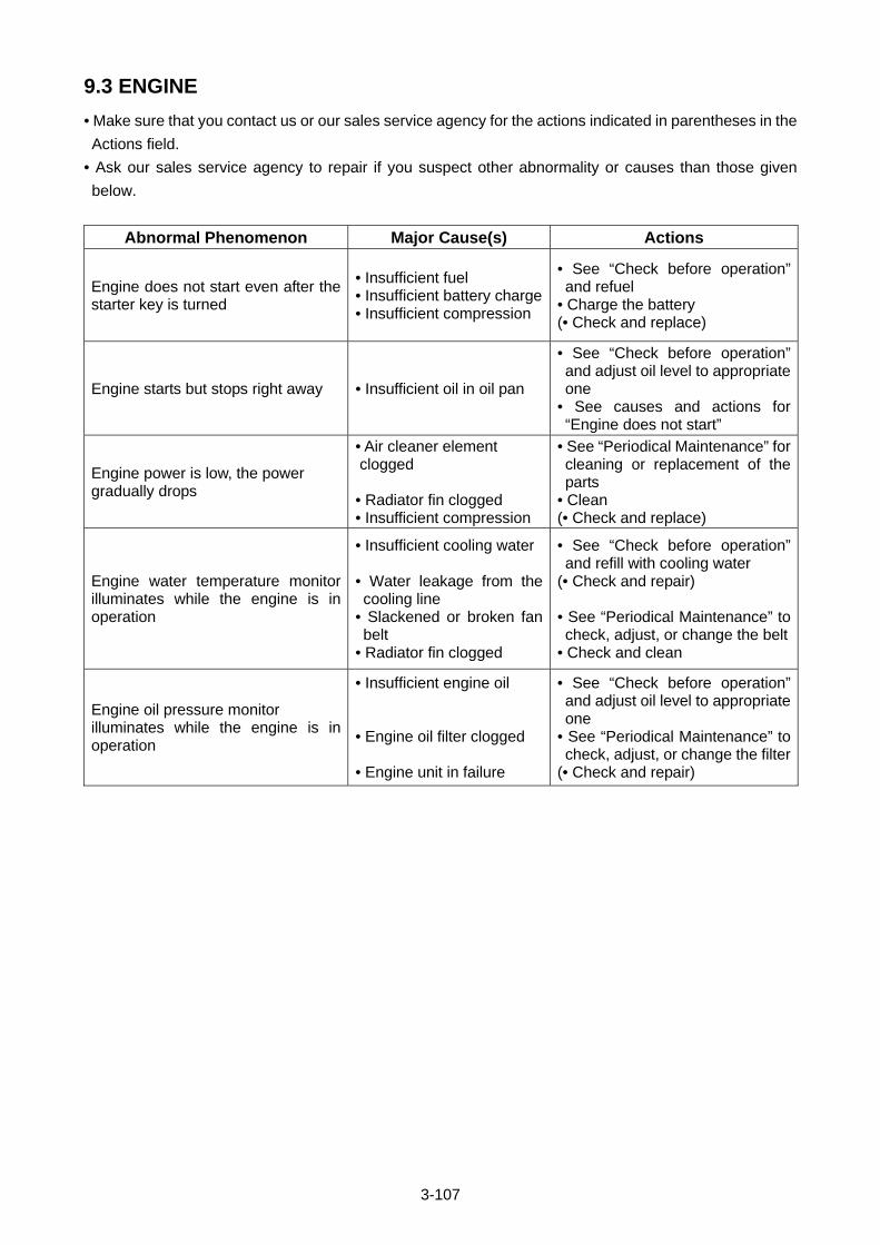
3-107
9.3 ENGINE
• Make sure that you contact us or our sales service agency for the actions indicated in parentheses in the
Actions field.
• Ask our sales service agency to repair if you suspect other abnormality or causes than those given
below.
Abnormal Phenomenon Major Cause(s) Actions
Engine does not start even after the starter key is turned
• Insufficient fuel • Insufficient battery charge • Insufficient compression
• See “Check before operation” and refuel
• Charge the battery (• Check and replace)
Engine starts but stops right away • Insufficient oil in oil pan
• See “Check before operation” and adjust oil level to appropriate one
• See causes and actions for “Engine does not start”
Engine power is low, the power gradually drops
• Air cleaner element clogged • Radiator fin clogged • Insufficient compression
• See “Periodical Maintenance” for cleaning or replacement of the parts
• Clean (• Check and replace)
Engine water temperature monitor illuminates while the engine is in operation
• Insufficient cooling water • Water leakage from the cooling line
• Slackened or broken fan belt
• Radiator fin clogged
• See “Check before operation” and refill with cooling water
(• Check and repair) • See “Periodical Maintenance” to check, adjust, or change the belt
• Check and clean
Engine oil pressure monitor illuminates while the engine is in operation
• Insufficient engine oil • Engine oil filter clogged • Engine unit in failure
• See “Check before operation” and adjust oil level to appropriate one
• See “Periodical Maintenance” to check, adjust, or change the filter
(• Check and repair)


4-1
INSPECTION AND MAINTENANCE
1. PRECAUTIONS FOR MAINTENANCE 4- 2
2. BASIC MAINTENANCE 4- 4
3. LEGAL INSPECTION 4- 6
4. CONSUMABLES 4- 6
5. LUBRICATING OIL 4- 7
6. ACCESSORY TOOLS AND STANDARD TIGHTENING TORQUE 4- 8
7. INSPECTION AND MAINTENANCE LIST 4-10
8. MAINTENANCE PROCEDURES 4-12
4-2
1. PRECAUTIONS FOR MAINTENANCE Thorough understanding of the inspection and maintenance items is required to perform efficient
inspection and maintenance that contributes to safe use of this machine.
• Do not perform any inspection or maintenance that is not described in this manual. Potential serious accident or machine failure may occur if it is performed at the discretion of the individual. In the event that a judgment on the severity of a failure or malfunction is unable to be made, contact us or our sales service agency to request repair.
• In the event that a failure or malfunction is encountered while the machine is in operation or found during an inspection, report it to your employer or supervisor immediately. Contact us or our sales service agency to request repair accordingly.
• Inspection and maintenance should be performed with the machine placed on a level and strong footing.
[1] CHECK THE SERVICE METERS
Read the service meters daily to check for any maintenance item that reached the obligatory maintenance
period.
[2] USE GENUINE PARTS FOR REPLACEMENT
Always use Maeda genuine parts as specified in the parts catalogue for part replacement.
[3] USE PURE GREASE
Always use Maeda pure grease. The viscosity of grease must conform to specifications according to
ambient temperature.
[4] USE CLEAN OIL AND GREASE
Always use clean oil or grease, and keep in a secure container to reduce contact with impurities.
[5] KEEP THE MACHINE CLEAN
Keep the machine clean to facilitate the detection of a malfunction. Especially keep the grease nipple,
breather, and oil level gauge (oil access door) clean to prevent impurities from entering the machine.
[6] HANDLE WATER AND OIL AT ADEQUATE TEMPERATURE
Drainage, drain oil, and exhaust filter will be at elevated temperatures immediately after the machine is
stopped. Only replace drainage, drain oil, and filter only after they drop in temperature for safety.
If the oil is cold, raise the temperature of the oil to approx. 20°C to 40°C.
[7] CHECK DRAIN OIL AND OIL FILTER
For replacement of oil and filter, check the drain oil and exhaust filter to make sure no a considerable
amount of metal powder or foreign objects is present.
[8] CAUTIONS FOR LUBRICATION
Do not remove the strainer to lubricate if it is attached to the lubrication opening.
[9] PROTECT OIL FROM IMPURITIES
Avoid dust when inspecting and replacing the oil to keep impurities out of the oil.
[10] ATTACH A WARNING TAG
When draining coolant and oil, always attach a warning tag to the travelling operation unit to prevent of
accidental engine ignition.
[11] FOLLOW SAFETY PRECAUTIONS
Safety precautions provided on the machine should always be followed when using the machine.
4-3
[12] CAUTIONS FOR WELD REPAIR
• Make sure the machine is turned off. (Turn OFF the start switch)
• Do not continuously apply 200V or greater.
• Ground the machine within 1 meter from the welding point.
• Be sure to disconnect the connectors of the remote controller, moment limiting indicator, and moment li
miting converter.
• Remove the negative terminal (-) of the battery.
• Make sure no sealing or bearing is present between the welding point and the grounding point.
Potential damage to sealing may occur due to sparks if disregarded.
• Do not ground around the boom pin or the hydraulic cylinder.
Potential damage to a plated section may occur due to sparks if disregarded.
[13] KEEP FROM FLAME
Always clean the parts with non-combustible cleaning agent or light oil.
Keep the machine away from flame when using light oil.
[14] KEEP THE ATTACHMENT SURFACE CLEAN
Be sure to clean the attachment surface after removing a part to which the O-ring and gasket sealing are
attached.
Replace the part with a new one with the O-ring and gasket reattached.
[15] Empty YOUR POCKETS
Always empty your pockets before performing inspection and maintenance of the machine in a downward
direction with the cover opened.
[16] ASSURE SAFE RUBBER TRACK
When performing crane operation in a rocky location, make sure of no damage to the rubber track and no
looseness, cracks or abrasion of bolts and nuts. Loosen the tension of the crawler tread more than usual.
[17] CAUTIONS FOR MACHINE WASH
• Do not direct a jet of steam to the electrical parts and connector.
• Keep the operation panel dry.
• Wash the machine with a clean cloth, rinsing off dirt and dust.
[18] PRE- AND POST-WORK INSPECTION
Before performing crane operation in muddy water, rain, snow or on the coast, always check for loose
fitting plugs and valves. Post-operation inspection requires checks to all units for cracks and superficial
damage; looseness of bolts and nuts, after the machine has been washed.
Carry out early greasing. Grease the operating pin that enters the muddy water on a daily basis.
[19] CAUTIONS FOR WORKING ON A DUSTY SITE
The following precautions should be observed when working on a dusty site.
• Occasionally check the air cleaner for clogging.
• Clean and replace the fuel filter in a timely manner.
• Be sure to clean the electrical parts, especially the starter and alternator, to protect them from dust.
[20] DO NOT MIX OIL
Never mix different types of oil under any circumstance.
Replace the oil entirely when replenishing a different type of oil.
Always use Maeda genuine parts for part replacement.
4-4
2. BASIC MAINTENANCE [1] OIL HANDLING
• Oil is used under extremely harsh conditions (high temperature, high pressure) in the engine and working
device, which causes the oil to undergo deterioration with operating time.
Always use oil that meets requirements such as grade and operating temperature defined in the operation
manual. Be sure to perform periodic replacement of oil irrespective of contamination in the oil.
• Oil is equivalent to human blood. Exercise due caution to handle oil, keeping impurities (such as water, metal
powder or dust) out of oil. Most of mechanical failures are attributed to intrusion of impurities.
Extra caution is required to prevent impurities entering during machine storage and lubrication.
• Do not mix oil with other oil of different grade or brand.
• Oil lubrication must conform to the designated quantity of oil.
Failure to lubricate at adequate quantity can lead to a machine failure.
• In the event that oil used in the working device turns cloudy, potential intrusion of moisture or air into the oil
may be considered. Contact us or our sales service agency.
• When replacing oil, always replace the relevant filter as well.
•”ISO VG32” is adopted for a hydraulic oil system as factory default.
Do not use any other hydraulic oil that is not recommended by us. Failure to follow the instruction may cause
the filters to get clogged. A small amount of oil remaining in piping and cylinders does not cause problems
even when mixed with other oil.
[2] FUEL HANDLING
• The fuel pump is precision equipment that becomes inoperative if fuel containing moisture or impurities is
used. Extra caution is required to prevent impurities from finding their way into the machine during storage and
lubrication.
• Do not remove the strainer when replenishing fuel.
• Always use fuel that meets requirements such as grade and operating temperature defined in the operation
manual.
• Ensure that the fuel tank is filled up after finishing daily work to prevent condensation of the humid air inside
the fuel tank that will result in intrusion of moisture.
• Drain deposits and water out of the fuel tank before starting the engine or approximately 10 minutes after fuel
replenishment.
• The air should be released from the circuit when the machine runs out of fuel or when the fuel filter is replaced.
• Clean the tank and fuel system if any foreign substances enter the fuel tank.
[3] STOCKING AND STORAGE OF OIL AND FUEL
• Store oil and fuel indoors to keep impurities such as moisture or dust out of them.
• When storing oil and fuel in drums for a long time, line the drums horizontally aligning the drum bungs
sideways (to store them away from moisture). Be sure to cover the drums with a waterproof sheet if storing
them outside.
• To prevent deterioration of oil and fuel resulted from long-term storage; employ the first-in first-out for using oil
and fuel.
[4] GREASE HANDLING
• Grease is designed to prevent the joints from rattling and making noise.
• A nipple that is not described in the Periodic Maintenance chapter is used for overhauls, which requires no
grease replenishment. Grease the nipple if a long-term use hinders its smoothness.
• Wipe off old grease squeezed out after greasing. Extra care is required to wipe a part that the adhesion of
sands and dust accelerates the wearing away of the rotating part.
4-5
[5] FILTER HANDLING
• A filter is an extremely important part that keeps major equipment free from impurities in oil, fuel, and the air
circuit, which prevents an associated failure. Periodic replacement of the filter is required in accordance with
the Operation Manual. The replacement period should be shortened in responses to harsh operating
environments or the amount of oil used.
• Do not reuse any washed filters (cartridge type one) under any circumstances.
• After replacing an oil filter, check the used filter for any metal powder.
If metal powder is found on the used filter, contact us or our sales service agency.
• Always unpack the replacement filter prior to its use.
• Always use Maeda genuine filters.
[6] COOLANT HANDLING
• The river water contains a large amount of calcium and impurities. Use of the river water results in
accumulation of water stain in the engine and radiator, which causes heat exchange error leading to overheat.
Do not use non-potable water.
• Always use antifreeze following precautions stated in the Operation Manual.
• Keep antifreeze from flame. Antifreeze is a flammable solution.
• The mixing proportion of antifreeze varies with outside air temperature. See “Maintenance 8.11 Every 1000
Hours [2] Cleaning engine cooling system” for the mixing proportions.
• In the event of overheating, replenish coolant with the engine cold.
• The machine low in coolant may cause overheating and corrosion attributed to aeration.
[7] ELECTRICAL PART HANDLING
• The electrical parts are susceptible to water damage and damaged coating. A current leakage is developed if
the electrical parts are wetted or have damaged coating, which causes the machine to go out of order and
malfunction. Exercise due caution when handling the electrical parts.
• Inspection and maintenance include the checking of belt tension, belt damage, and battery electrolyte level.
• Never remove and disassemble equipment (electrical parts) from the machine.
• Only optional electrical parts that accompany the machine can be installed.
• Keep the electrical parts away from water when the machine is washed and used in the rain.
• When using the machine on coastal areas, keep the electrical parts free of water and impurities to prevent
corrosion.
[8] HYDRAULIC EQUIPMENT HANDLING
• Hydraulic equipment will be at elevated temperatures during and immediately after operation. Hydraulic
equipment operates under high pressure. The following precautions should be observed when performing
inspection and maintenance of hydraulic equipment.
• Place the machine in travel position on a level surface to inhibit the application of pressure to the cylinder circuit.
• Be sure to stop the engine.
• Hydraulic oil and lubricating oil will be at elevated temperatures and high pressure immediately after equipment comes to
a stop. Perform inspection and maintenance only after the oil drop in temperature for safety. An internal pressure may be
exerted despite temperature drop. When removing the plugs, screws and hose joints, stand aside and provide gradual
loosening to decompress.
• Be sure to release the pressure by removing the air from the hydraulic oil tank before performing inspection and
maintenance of the hydraulic circuit.
• Inspection and maintenance include hydraulic oil level check and replacement of the filters and hydraulic oil.
• Check the O-ring for scratches when removing the high-pressure hose. If scratches are found, replace the
O-ring.
• Bleeding the air from the hydraulic circuit is required after the following tasks are performed: replacement and
cleaning of the hydraulic oil filter element and strainer, repair and replacement of hydraulic equipment, and
hydraulic piping replacement.
4-6
3. LEGAL INSPECTION If periodic inspection for machine safety assurance is stipulated by laws and regulations of your country,
perform inspection complying with the inspection items listed below.
1. Make sure no abnormal event is present in the safety devices.
2. Check the hoisting accessories including hook block for any abnormalities.
3. Check the winch wire rope end and wire clip for breakages.
4. Replace the wire rope promptly if it is damaged.
5. Check the hydraulic hose for oil leaks and friction flaws on the surface. Replace the hose if a surface
flaw is detected.
6. Check the structural parts including the boom for cracks and deformations.
7. Check for loose or missing mounting bolts and joints.
8. Check if the booms perform proper operation and stop in extending, retracting, raising, lowering, and
slewing.
If a malfunction is found, contact us or our sales service agency.
4. CONSUMABLES Consumables such as a filter element and wire rope are to be replaced upon periodic maintenance or prior
to the wear limit. Proper replacement of consumables delivers increased economy in machine use.
Always use Maeda genuine parts for part replacement.
See the parts catalogue for part numbers when ordering parts.
[LIST OF CONSUMABLES]
Part Replacement cycle
Hydraulic oil return filter Every 500 hrs
Cylinder gasket 3 yrs
Boom slide plate Every 3 yrs
Winch wire rope Every 3 yrs
Boom extending wire rope Every 3 yrs
Boom retracting wire rope Every 3 yrs
The cycles marked with a “ ” in Replacement cycle include a halt period.
Contact us or our sales service agency for part replacement.
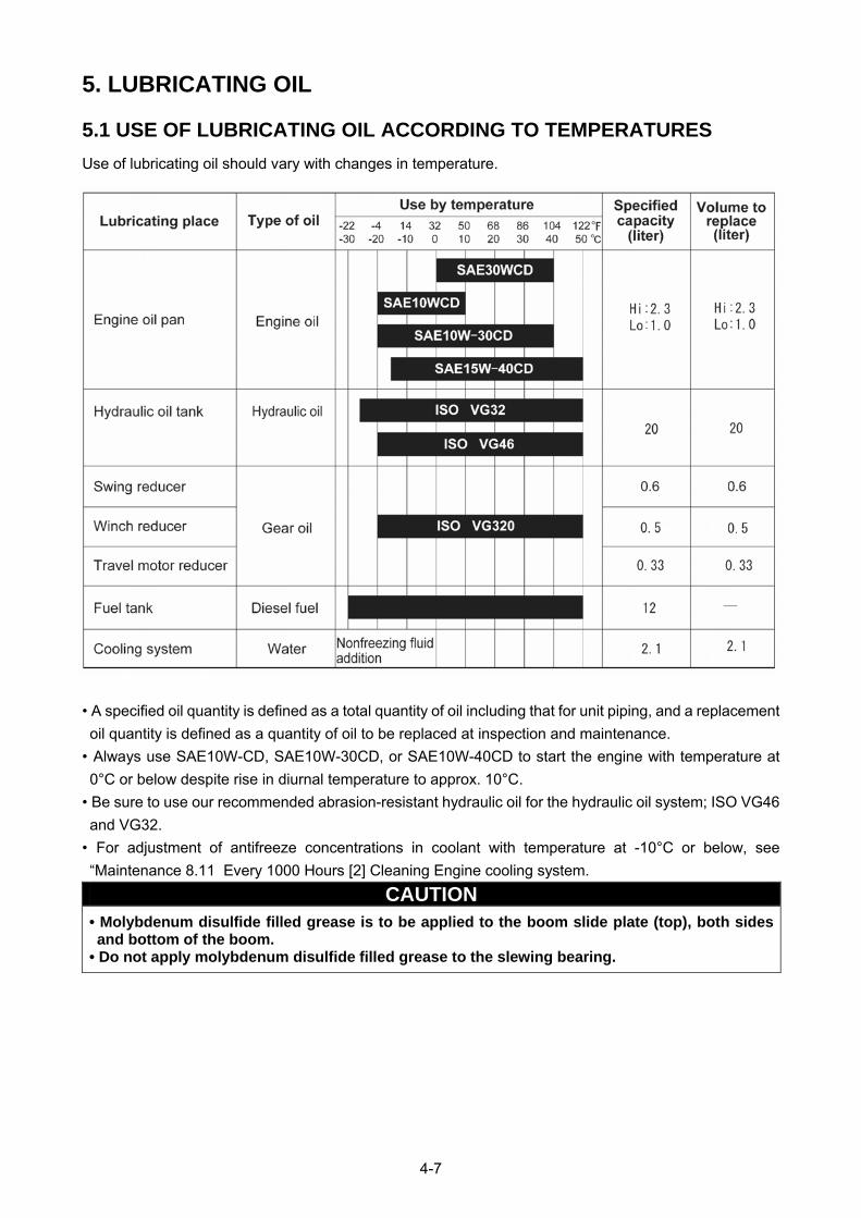
4-7
5. LUBRICATING OIL
5.1 USE OF LUBRICATING OIL ACCORDING TO TEMPERATURES
Use of lubricating oil should vary with changes in temperature.
• A specified oil quantity is defined as a total quantity of oil including that for unit piping, and a replacement
oil quantity is defined as a quantity of oil to be replaced at inspection and maintenance.
• Always use SAE10W-CD, SAE10W-30CD, or SAE10W-40CD to start the engine with temperature at
0°C or below despite rise in diurnal temperature to approx. 10°C.
• Be sure to use our recommended abrasion-resistant hydraulic oil for the hydraulic oil system; ISO VG46
and VG32.
• For adjustment of antifreeze concentrations in coolant with temperature at -10°C or below, see
“Maintenance 8.11 Every 1000 Hours [2] Cleaning Engine cooling system.
CAUTION • Molybdenum disulfide filled grease is to be applied to the boom slide plate (top), both sides and bottom of the boom.
• Do not apply molybdenum disulfide filled grease to the slewing bearing.

4-8
6. ACCESSORY TOOLS AND
STANDARD TIGHTENING TORQUE
6.1 ACCESSORY TOOLS
Contact us or our sales service agency to request a tool for inspection and maintenance, when necessary.
6.2 STANDARD TIGHTENING TORQUE LIST
Torque the metric bolts and nuts with no specific indication to the values
shown in this table.
Adequate tightening torque is determined with respect to a width across flat
(b) of a bolt or nut.
[Table 1]
[1] Bolt marked with “8.8” (strength classification) on its head
[2] Bolt marked with “10.9” (strength classification) on its head
Tightening torque {N▪m (kgf▪m)} Tightening torque {N▪m (kgf▪m)}
Nominal size
(a; mm)
Width across flat (b; mm)
Target value Tolerance Target value Tolerance
6 10 7.8 (0.80) 6.8-9.0 (0.70-0.92) 11.0 (1.1) 9.4-12.7 (0.93-1.26)
8 13 19.0 (1.95) 16.5-21.9 (1.70-2.24) 27.0 (2.7) 23.0-31.1 (2.3-3.10)
10 17 37.5 (3.85) 32.6-43.1 (3.35-4.43) 53.0 (5.4) 45.0-61.0 (4.6-6.21)
12 19 65.5 (6.70) 57.0-75.3 (5.85-7.70) 93.0 (9.5) 79.0-107 (8.10-10.9)
14 22 104 (10.6) 90.4-120 (9.2-12.2) 148 (15.1) 126-170 (12.8-17.4)
16 24 163 (16.6) 142-187 (14.4-19.1) 231 (23.5) 196-266 (20.0-27.0)
18 27 224 (22.8) 195-258 (19.8-26.2) 317 (32.3) 269-365 (27.5-37.1)
20 30 318 (32.4) 277-366 (28.2-37.3) 450 (45.9) 383-518 (39.0-52.8)
22 32 432 (44.0) 376-497 (38.3-50.6) 612 (62.4) 520-704 (53.0-71.8)
24 36 549 (56.0) 477-631 (48.7-64.4) 778 (79.3) 661-895 (67.4-91.2)
27 41 804 (81.9) 699-925 (71.2-94.2) 1130 (116) 961-1300 (98.6-133)
30 46 1090 (111) 948-1250 (96.5-128) 1540 (158) 1310-1770 (134-182)
33 50 1485 (151) 1290-1710 (131-174) 2100 (214) 1790-2410 (182-246)
36 55 1910 (194) 1660-2200 (167-223) 2700 (275) 2300-3100 (234-316)
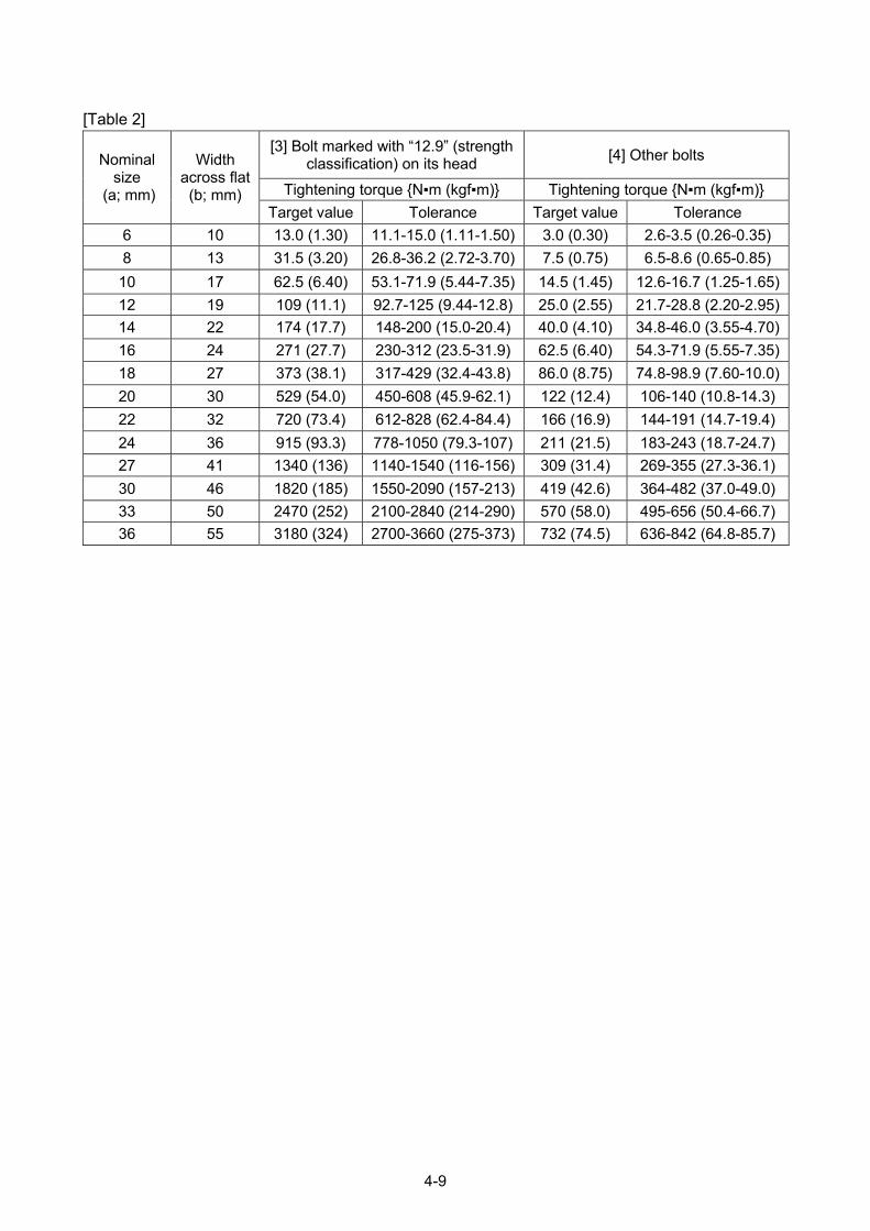
4-9
[Table 2]
[3] Bolt marked with “12.9” (strength classification) on its head
[4] Other bolts
Tightening torque {N▪m (kgf▪m)} Tightening torque {N▪m (kgf▪m)}
Nominal size
(a; mm)
Width across flat (b; mm)
Target value Tolerance Target value Tolerance
6 10 13.0 (1.30) 11.1-15.0 (1.11-1.50) 3.0 (0.30) 2.6-3.5 (0.26-0.35)
8 13 31.5 (3.20) 26.8-36.2 (2.72-3.70) 7.5 (0.75) 6.5-8.6 (0.65-0.85)
10 17 62.5 (6.40) 53.1-71.9 (5.44-7.35) 14.5 (1.45) 12.6-16.7 (1.25-1.65)
12 19 109 (11.1) 92.7-125 (9.44-12.8) 25.0 (2.55) 21.7-28.8 (2.20-2.95)
14 22 174 (17.7) 148-200 (15.0-20.4) 40.0 (4.10) 34.8-46.0 (3.55-4.70)
16 24 271 (27.7) 230-312 (23.5-31.9) 62.5 (6.40) 54.3-71.9 (5.55-7.35)
18 27 373 (38.1) 317-429 (32.4-43.8) 86.0 (8.75) 74.8-98.9 (7.60-10.0)
20 30 529 (54.0) 450-608 (45.9-62.1) 122 (12.4) 106-140 (10.8-14.3)
22 32 720 (73.4) 612-828 (62.4-84.4) 166 (16.9) 144-191 (14.7-19.4)
24 36 915 (93.3) 778-1050 (79.3-107) 211 (21.5) 183-243 (18.7-24.7)
27 41 1340 (136) 1140-1540 (116-156) 309 (31.4) 269-355 (27.3-36.1)
30 46 1820 (185) 1550-2090 (157-213) 419 (42.6) 364-482 (37.0-49.0)
33 50 2470 (252) 2100-2840 (214-290) 570 (58.0) 495-656 (50.4-66.7)
36 55 3180 (324) 2700-3660 (275-373) 732 (74.5) 636-842 (64.8-85.7)

4-10
7. INSPECTION AND MAINTENANCE LIST Inspection and maintenance items Page
8.1 INITIAL 10 HOUR MAINTENANCE (Only the first maintenance of a new machine) 4-12
[1] GREASING MACHINE UNITS 4-25
8.2 INITIAL 50 HOUR MAINTENANCE (Only the first maintenance of a new machine) 4-12
[1] REPLACEMENT ENGINE OIL AND REPLACE FILTER CARTRIDGE 4-30
[2] OIL REPLACEMENT IN HYDRAULIC OIL TANK 4-39
[3] REPLACEMENT HYDRAULIC OIL RETURN FILTER CARTRIDGE 4-33
[4] CHECKING / ADJUSTMENT ALTERNATOR BELT TENSION 4-28
8.3 INITIAL 250 HOUR MAINTENANCE (Only the first maintenance of a new machine) 4-12
[1] OIL REPLACEMENT IN SLEWING REDUCTION GEAR CASE 4-41
[2] OIL REPLACEMENT IN WINCH REDUCTION GEAR CASE 4-43
[3] OIL REPLACEMENT IN TRAVELLING MOTOR REDUCTION GEAR CASE 4-45
8.4 INSPECTION OF BEFORE OPERATION 4-12
2.1.1 VISIBLE CHECKS 3-36
[1] INSPECTION AROUND ENGINE 3-37
[2] INSPECTION OF HYDRAULIC SYSTEM OF UNDERCARRIAGE 3-37
[3] INSPECTION OF UNDERCARRIAGE 3-37
[4] INSPECTION OF OUTRIGGER 3-37
[5] INSPECTION OF OUTRIGGER CYLINDER 3-37
[6] INSPECTION OF POST 3-37
[7] INSPECTION OF DERRICK CYLINDER 3-37
[8] INSPECTION OF BOOM 3-37
[9] INSPECTION OF TELESCOPE CYLINDER 3-37
[10] INSPECTION OF WIRE ROPE 3-37
[11] INSPECTION OF OVER-HOIST PREVENTIVE DEVICE 3-38
[12] INSPECTION OF WINCH MOTOR 3-38
[13] INSPECTION OF WINCH DRUM 3-38
[14] INSPECTION OF HOOK BLOCK 3-38
2.1.2 CHECKING BEFORE STARTING ENGINE 3-39
[1] CHECKING / REFILLING ENGINE COOLING WATER 3-39
[2] CHECKING/CLEANING RADIATOR AND OIL COOLER FINS 3-40
[3] CHECKING/REFILLING OIL LEVEL IN ENGINE OIL PAN 3-41
[4] CHECKING/REFUELING FUEL LEVEL IN FUEL TANK 3-42
[5] CHECKING/CLEANING WATER SEPARATOR 3-43
[6] CHECKING/CLEANING FUEL FILTER POT 3-44
[7] CHECKING/REFILLING OIL LEVEL IN HYDRAULIC OIL TANK 3-45
[8] CHECKING/REFILLING OIL LEVEL IN SLEWING REDUCTION GEAR CASE 3-46
[9] CHECKING/REFILLING BATTERY ELECTROLYTE LEVEL 3-47
[10] CHECKING HORN FOR OPERATION 3-48
[11] CHECKING HEADLIGHTS FOR OPERATION 3-48
[12] CHECKING FUSE BOX FOR DAMAGE 3-49
[13] CHECK CRACK, DEFORMATION OR DAMAGE OF BOOM AND FRAME 3-49
[14] CHECK DEFORMATION, DAMAGE OR WEAR OF WIRE ROPE 3-49

4-11
Inspection and maintenance items Page
2.1.3 CHECKING AFTER STARTING ENGINE 3-50
[1] CHECKING / ADJUSTING RUBBER TRACK TENSION 3-50
[2] CHECKING RUBBER TRACKS FOR DAMAGE AND WEAR 3-53
[3] CHECKING OUTRIGGER OPERATION 3-54
[4] CHECKING CRANE OPERATIONS 3-55
[5] CHECKING OVER HOIST DETECTOR FOR OPERATION 3-56
[6] CHECKING MOMENT LIMITER FOR OPERATION 3-56
[7] CHECKING ENGINE EMERGENCY STOP SWITCH FOR OPERATION 3-57
[8] CHECKING ENGINE EXHAUST GAS COLOUR, NOISE AND VIBRATION 3-57
8.5 IRREGULAR MAINTENANCE 4-13
[1] REPLACEMENT RUBBER TRACK 4-13
[2] REPLACEMENT WINCH WIRE ROPE 4-15
[3] CHECKING/ADJUSTMENT BOOM TELESCOPING WIRE ROPE 4-19
8.6 MAINTENANCE EVERY 30 HOURS 4-22
[1] CHECKING / CLEANING / REPLACE AIR CLEANER ELEMENT 4-22
8.7 MAINTENANCE EVERY 50 HOURS 4-24
[1] DRAINING CONTAMINANT WATER/DEPOSITS IN FUEL TANK 4-24
[2] GREASING MACHINE UNITS 4-25
8.8 MAINTENANCE EVERY 100 HOURS 4-27
[1] CHECK OIL LEVEL IN WINCH REDUCTION GEAR CASE, AND ADD OIL 4-27
8.9 MAINTENANCE EVERY 250 HOURS 4-28
[1] CHECKING / ADJUSTMENT ALTERNATOR BELT TENSION 4-28
[2] CHECKING / REFILLING OIL IN TRAVELLING MOTOR REDUCTION GEAR CASE 4-29
8.10 MAINTENANCE EVERY 500 HOURS 4-30
[1] REPLACEMENT ENGINE OIL AND REPLACE FILTER CARTRIDGE 4-30
[2] REPLACEMENT FUEL FILTER CARTRIDGE 4-32
[3] REPLACEMENT HYDRAULIC OIL RETURN FILTER CARTRIDGE 4-33
8.11 MAINTENANCE EVERY 1000 HOURS 4-35
[1] REPLACEMENT AIR CLEANER ELEMENT 4-35
[2] CLEANING ENGINE COOLING SYSTEM 4-36
[3] OIL REPLACEMENT IN HYDRAULIC OIL TANK 4-39
[4] OIL REPLACEMENT IN SLEWING REDUCTION GEAR CASE 4-41
[5] OIL REPLACEMENT IN WINCH REDUCTION GEAR CASE 4-43
[6] OIL REPLACEMENT IN TRAVELLING MOTOR REDUCTION GEAR CASE 4-45
8.12 MAINTENANCE EVERY 2000 HOURS 4-46
[1] INSPECTION/ADJUSTMENT ENGINE VALVE CLEARANCE 4-46
[2] CHECKING ALTERNATOR AND STARTER 4-46
4-12
8. MAINTENANCE PROCEDURES
8.1 INITIAL 10 HOUR MAINTENANCE
The following maintenance should be performed after 10-hours of operation, limited to the first
maintenance of a new machine.
[1] GREASING MACHINE UNITS
See “Maintenance 8.7 Every 50 Hours” for maintenance items and procedure.
8.2 INITIAL 50 HOUR MAINTENANCE
The following maintenance should be performed after 50-hours of operation, limited to the first
maintenance of a new machine.
[1] REPLACEMENT ENGINE LUBRICATING OIL AND OIL FILTER CARTRIDGE
See “Maintenance 8.10 Every 500 Hours” for maintenance items and procedure.
[2] OIL REPLACEMENT IN HYDRAULIC OIL TANK
See “Maintenance 8.11 Every 1000 Hours” for maintenance items and procedure.
[3] REPLACEMENT HYDRAULIC OIL RETURN FILTER
See “Maintenance 8.10 Every 500 Hours” for maintenance items and procedure.
[4] CHECKING / ADJUSTMENT ALTERNATOR BELT TENSION
See “Maintenance 8.9 Every 250 Hours” for maintenance items and procedure.
8.3 INITIAL 250 HOUR MAINTENANCE
The following maintenance should be performed after 250-hours of operation, limited to the first
maintenance of a new machine.
[1] OIL REPLACEMENT SLEWING REDUCTION GEAR CASE
See “Maintenance 8.11 Every 1000 Hours” for maintenance items and procedure.
[2] OIL REPLACEMENT WINCH MOTOR REDUCTION GEAR CASE
See “Maintenance 8.11 Every 1000 Hours” for maintenance items and procedure.
[3] OIL REPLACEMENT TRAVELLING MOTOR REDUCTION GEAR CASE
See “Maintenance 8.11 Every 1000 Hours” for maintenance items and procedure.
8.4 CHECKING BEFORE OPERATION
Inspections specified in this section are required to be completed prior to starting an engine first of the da
y.
See “Maintenance 7. Inspection and Maintenance List” for the inspection and maintenance items
See “Operation 2.1 Checking Before Operation” for before operation inspection items and procedure.
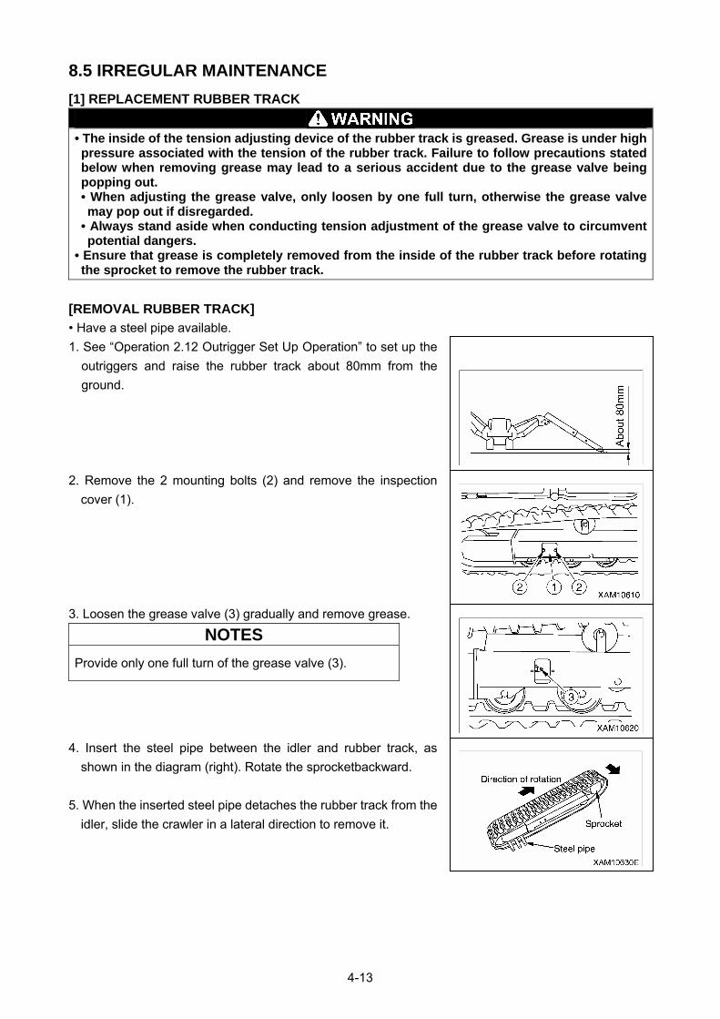
4-13
8.5 IRREGULAR MAINTENANCE
[1] REPLACEMENT RUBBER TRACK
• The inside of the tension adjusting device of the rubber track is greased. Grease is under high pressure associated with the tension of the rubber track. Failure to follow precautions stated below when removing grease may lead to a serious accident due to the grease valve being popping out. • When adjusting the grease valve, only loosen by one full turn, otherwise the grease valve may pop out if disregarded.
• Always stand aside when conducting tension adjustment of the grease valve to circumvent potential dangers.
• Ensure that grease is completely removed from the inside of the rubber track before rotating the sprocket to remove the rubber track.
[REMOVAL RUBBER TRACK]
• Have a steel pipe available.
1. See “Operation 2.12 Outrigger Set Up Operation” to set up the
outriggers and raise the rubber track about 80mm from the
ground.
2. Remove the 2 mounting bolts (2) and remove the inspection
cover (1).
3. Loosen the grease valve (3) gradually and remove grease.
NOTES
Provide only one full turn of the grease valve (3).
4. Insert the steel pipe between the idler and rubber track, as
shown in the diagram (right). Rotate the sprocketbackward.
5. When the inserted steel pipe detaches the rubber track from the
idler, slide the crawler in a lateral direction to remove it.
4-14
[INSTALLATION RUBBER TRACK]
• Have a grease gun available.
• Have a steel pipe available.
1. See “Operation 2.12 Outrigger Setting Operation” to set the
outriggers and raise the rubber track again about 80mm from the
ground.
2. With the rubber track engaged with the sprocket, put the crawler
on the idler.
3. With the sprocket rotating backward, push the rubber track in to
stop rotation.
4. Insert the steel pipe between the idler and rubber track again,
and re-rotate the sprocket to put the crawler on the idler properly.
5. Stop rotation, and ensure that the rubber track is on the sprocket
and idler properly.
6. Make a tension adjustment to the rubber track according to
“Operation 2.1.3 Checking after Starting Engine [1] Checking /
adjustment Rubber Track” in the Operation section of the
manual.
7. Ensure that adequate engagement and tension of the rubber
track, sprocket, and idler are obtained.
8. See “Operation 2.22 Outrigger Stowing Operation” to stow the
outriggers and lower the machine onto the ground.
4-15
[2] REPLACEMENT WINCH WIRE ROPE
Always wear leather work gloves when replacing the wire rope.
CAUTION • The diameter of the wire rope is measured at points where the wire repeatedly runs through the sheave. A mean value needs to be determined through three-way measurement. (A measurement should be performed at several points, spacing between the points.)
• Do not use old wire rope regardless of the frequency of use. • Always use Maeda genuine wire rope.
[CRITERIA FOR WINCH WIRE ROPE REPLACEMENT]
A wire rope undergoes wear and tear over time.
Prompt replacement is required if any of the following
appears in the wire rope.
• 10% or more of strands (except a filler wire) in a twist of
the wire rope (6 crests) are broken.
NOTES
Change winching/boom telescoping wire rope when 13 or more wires are broken.
• Wear equivalent to 7% or more of a nominal diameter occurs in
the wire rope diameter.
NOTES
• Change the 9-mm diameter wire rope when reduced to 8.4 mm.• Change the 8-mm diameter wire rope when reduced to 7.5 mm.• Change the 7-mm diameter wire rope when reduced to 6.6 mm.• Change the 6-mm diameter wire rope when reduced to 5.6 mm.• Change the 5-mm diameter wire rope when reduced to 4.7 mm.
• A kink is formed.
• Considerable deformation or corrosion is developed.
• A faulty end socket is used.
4-16
[REMOVAL WINCH WIRE ROPE]
Use the following procedure to remove the wire rope.
1. Place the machine on a level and firm surface.
2. Place the boom telescoping lever in the “Extend” position (push
it toward the front) to extend the boom slightly.
3. Place the winch lever in the “Down” position (push it toward the
front) to lower the hook block on the ground.
4. Undo the wedge socket fixing bolt (2) and remove the wedge
socket (3).
5. Remove the wire clip (4).
6. Pull the wire rope (5) out of the wedge socket (3), following the
procedure provided below.
(1) Bring a 4 to 6mm round bar (6) into contact with the rope
wedge (7).
(2) Remove the rope wedge (7), lightly tapping the round bar (6)
with a hammer in the direction indicated by the arrow (a).
7. Place the winch lever in the “Down” position (push it toward the
front) to wind up the wire rope (5) from the winch drum.
8. With the wire rope wound off from the winch drum; detach the
end of the wire rope (5) from the winch drum (8) by following the
procedure provided below.
(1) Bring a 4 to 6mm round bar (6) into contact with the rope
wedge (9).
(2) Remove the rope wedge (9), lightly tapping the round bar (6)
with a hammer in the direction indicated by the arrow (b).
9. Wind up the remaining wire rope (5) completely.
Removal of the winch wire rope is completed.
4-17
[INSTALATION WINCH WIRE ROPE]
Be sure to attach the rope wedge properly to secure the wire rope. Serious accidents may occur if the wire rope is detached during crane operations.
CAUTION • Avoid irregular winding of the wire rope on the winch drum. • Always hoist an object (2.9 to 4.9KN {300 to 500kg}) with the boom extended and raised fully immediately after attaching a new rope. Repeat raising and lowering the hook several times until the new rope conforms.
• The wire rope is coiled. Exercise caution not to form a kink in the rope when winding it up. Be sure to unravel by rotating the rope to pull it out of the winch drum.
Use the following procedure to attach the wire rope.
1. With the end of the wire rope held, draw the wire rope (5)
through the weight of the over hoist detector, the load sheave (1)
at the boom end, the wire guide (2) of No. 2 boom, the guide
sheave (3) of No.1 boom, and also the idler sheave (4) of No.1
boom.
2. Draw the wire rope (5) through the attachment hole of the winch
drum (8). Secure the wire rope (5) to the winch drum (8),
following the procedure provided below.
(1) Draw the slackened wire rope (5) through the winch drum (8).
(2) The rope wedge (9) should be in position (a). Pass the wire
rope (5) around the rope wedge and yank at the rope in the
direction indicated by the arrow.
Adjust the length of the wire rope (5) to keep the end of the
wire rope from protruding from the narrow hole in the winch
drum (8).
3. Place the winch lever in the “Up” position (pull toward you)
slowly to wind up the wire rope (5) on to the winch drum (8).
4. In response to the number of falls (4-falls), draw the wire rope (5)
through the load sheave at the boom end, the hook block sheave,
the guide sheave, and weight of the over hoist detector.
4-falls
2-falls 1-fall
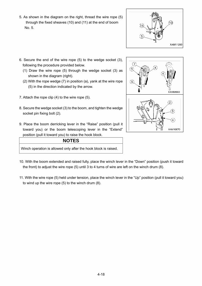
4-18
5. As shown in the diagram on the right, thread the wire rope (5)
through the fixed sheaves (10) and (11) at the end of boom
No. 5.
6. Secure the end of the wire rope (5) to the wedge socket (3),
following the procedure provided below.
(1) Draw the wire rope (5) through the wedge socket (3) as
shown in the diagram (right).
(2) With the rope wedge (7) in position (a), yank at the wire rope
(5) in the direction indicated by the arrow.
7. Attach the rope clip (4) to the wire rope (5).
8. Secure the wedge socket (3) to the boom, and tighten the wedge
socket pin fixing bolt (2).
9. Place the boom derricking lever in the “Raise” position (pull it
toward you) or the boom telescoping lever in the “Extend”
position (pull it toward you) to raise the hook block.
NOTES
Winch operation is allowed only after the hook block is raised.
10. With the boom extended and raised fully, place the winch lever in the “Down” position (push it toward
the front) to adjust the wire rope (5) until 3 to 4 turns of wire are left on the winch drum (8).
11. With the wire rope (5) held under tension, place the winch lever in the “Up” position (pull it toward you)
to wind up the wire rope (5) to the winch drum (8).
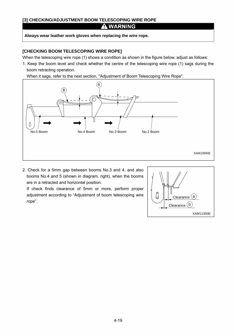
4-19
[3] CHECKING/ADJUSTMENT BOOM TELESCOPING WIRE ROPE
Always wear leather work gloves when replacing the wire rope.
[CHECKING BOOM TELESCOPING WIRE ROPE]
When the telescoping wire rope (1) shows a condition as shown in the figure below, adjust as follows:
1. Keep the boom level and check whether the centre of the telescoping wire rope (1) sags during the
boom retracting operation.
When it sags, refer to the next section, "Adjustment of Boom Telescoping Wire Rope".
2. Check for a 5mm gap between booms No.3 and 4, and also
booms No.4 and 5 (shown in diagram, right), when the booms
are in a retracted and horizontal position.
If check finds clearance of 5mm or more, perform proper
adjustment according to “Adjustment of boom telescoping wire
rope”.
XAM11350E
Clearance b
Clearance a
XAM10690E
No.4 BoomNo.5 Boom No.3 Boom No.2 Boom
86
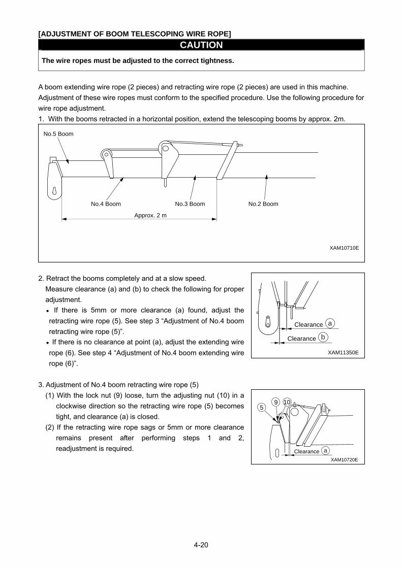
4-20
[ADJUSTMENT OF BOOM TELESCOPING WIRE ROPE]
CAUTION
The wire ropes must be adjusted to the correct tightness.
A boom extending wire rope (2 pieces) and retracting wire rope (2 pieces) are used in this machine.
Adjustment of these wire ropes must conform to the specified procedure. Use the following procedure for
wire rope adjustment.
1. With the booms retracted in a horizontal position, extend the telescoping booms by approx. 2m.
2. Retract the booms completely and at a slow speed.
Measure clearance (a) and (b) to check the following for proper
adjustment.
• If there is 5mm or more clearance (a) found, adjust the
retracting wire rope (5). See step 3 “Adjustment of No.4 boom
retracting wire rope (5)”.
• If there is no clearance at point (a), adjust the extending wire
rope (6). See step 4 “Adjustment of No.4 boom extending wire
rope (6)”.
3. Adjustment of No.4 boom retracting wire rope (5)
(1) With the lock nut (9) loose, turn the adjusting nut (10) in a
clockwise direction so the retracting wire rope (5) becomes
tight, and clearance (a) is closed.
(2) If the retracting wire rope sags or 5mm or more clearance
remains present after performing steps 1 and 2,
readjustment is required.
XAM11350E
Clearance b
Clearance a
XAM10710E
Approx. 2 m
No.5 Boom
No.4 Boom No.3 Boom No.2 Boom
XAM10720E
Clearance a
1095
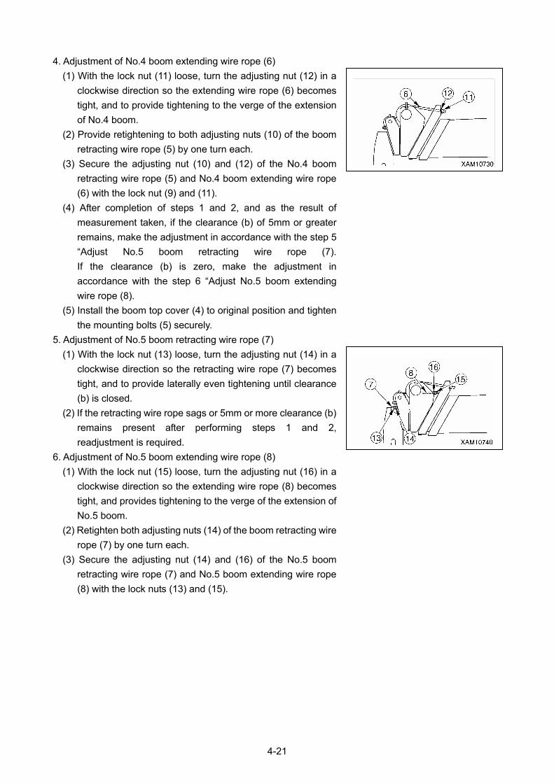
4-21
4. Adjustment of No.4 boom extending wire rope (6)
(1) With the lock nut (11) loose, turn the adjusting nut (12) in a
clockwise direction so the extending wire rope (6) becomes
tight, and to provide tightening to the verge of the extension
of No.4 boom.
(2) Provide retightening to both adjusting nuts (10) of the boom
retracting wire rope (5) by one turn each.
(3) Secure the adjusting nut (10) and (12) of the No.4 boom
retracting wire rope (5) and No.4 boom extending wire rope
(6) with the lock nut (9) and (11).
(4) After completion of steps 1 and 2, and as the result of
measurement taken, if the clearance (b) of 5mm or greater
remains, make the adjustment in accordance with the step 5
“Adjust No.5 boom retracting wire rope (7).
If the clearance (b) is zero, make the adjustment in
accordance with the step 6 “Adjust No.5 boom extending
wire rope (8).
(5) Install the boom top cover (4) to original position and tighten
the mounting bolts (5) securely.
5. Adjustment of No.5 boom retracting wire rope (7)
(1) With the lock nut (13) loose, turn the adjusting nut (14) in a
clockwise direction so the retracting wire rope (7) becomes
tight, and to provide laterally even tightening until clearance
(b) is closed.
(2) If the retracting wire rope sags or 5mm or more clearance (b)
remains present after performing steps 1 and 2,
readjustment is required.
6. Adjustment of No.5 boom extending wire rope (8)
(1) With the lock nut (15) loose, turn the adjusting nut (16) in a
clockwise direction so the extending wire rope (8) becomes
tight, and provides tightening to the verge of the extension of
No.5 boom.
(2) Retighten both adjusting nuts (14) of the boom retracting wire
rope (7) by one turn each.
(3) Secure the adjusting nut (14) and (16) of the No.5 boom
retracting wire rope (7) and No.5 boom extending wire rope
(8) with the lock nuts (13) and (15).
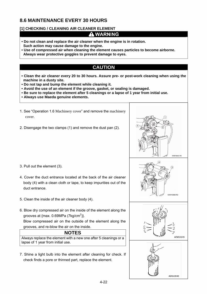
4-22
8.6 MAINTENANCE EVERY 30 HOURS
[1] CHECKING / CLEANING AIR CLEANER ELEMENT
• Do not clean and replace the air cleaner when the engine is in rotation. Such action may cause damage to the engine.
• Use of compressed air when cleaning the element causes particles to become airborne. Always wear protective goggles to prevent damage to eyes.
CAUTION
• Clean the air cleaner every 20 to 30 hours. Assure pre- or post-work cleaning when using the machine in a dusty site.
• Do not tap and bump the element while cleaning it. • Avoid the use of an element if the groove, gasket, or sealing is damaged. • Be sure to replace the element after 5 cleanings or a lapse of 1 year from initial use. • Always use Maeda genuine elements.
1. See “Operation 1.6 Machinery cover” and remove the machinery cover.
2. Disengage the two clamps (1) and remove the dust pan (2).
3. Pull out the element (3).
4. Cover the duct entrance located at the back of the air cleaner
body (4) with a clean cloth or tape, to keep impurities out of the
duct entrance.
5. Clean the inside of the air cleaner body (4).
6. Blow dry compressed air on the inside of the element along the
grooves at {max. 0.69MPa (7kg/cm2)}.
Blow compressed air on the outside of the element along the
grooves, and re-blow the air on the inside.
NOTES Always replace the element with a new one after 5 cleanings or a lapse of 1 year from initial use.
7. Shine a light bulb into the element after cleaning for check. If
check finds a pore or thinned part, replace the element.
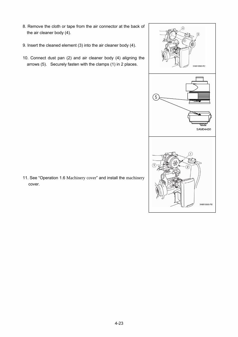
4-23
8. Remove the cloth or tape from the air connector at the back of
the air cleaner body (4).
9. Insert the cleaned element (3) into the air cleaner body (4).
10. Connect dust pan (2) and air cleaner body (4) aligning the
arrows (5). Securely fasten with the clamps (1) in 2 places.
11. See “Operation 1.6 Machinery cover” and install the machinery cover.
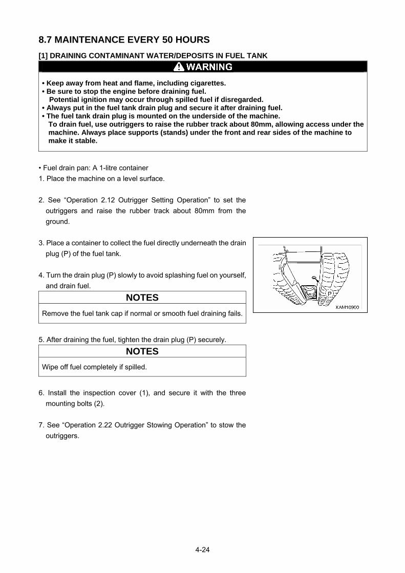
4-24
8.7 MAINTENANCE EVERY 50 HOURS
[1] DRAINING CONTAMINANT WATER/DEPOSITS IN FUEL TANK
• Keep away from heat and flame, including cigarettes. • Be sure to stop the engine before draining fuel.
Potential ignition may occur through spilled fuel if disregarded. • Always put in the fuel tank drain plug and secure it after draining fuel. • The fuel tank drain plug is mounted on the underside of the machine.
To drain fuel, use outriggers to raise the rubber track about 80mm, allowing access under the machine. Always place supports (stands) under the front and rear sides of the machine to make it stable.
• Fuel drain pan: A 1-litre container
1. Place the machine on a level surface.
2. See “Operation 2.12 Outrigger Setting Operation” to set the
outriggers and raise the rubber track about 80mm from the
ground.
3. Place a container to collect the fuel directly underneath the drain
plug (P) of the fuel tank.
4. Turn the drain plug (P) slowly to avoid splashing fuel on yourself,
and drain fuel.
NOTES
Remove the fuel tank cap if normal or smooth fuel draining fails.
5. After draining the fuel, tighten the drain plug (P) securely.
NOTES
Wipe off fuel completely if spilled.
6. Install the inspection cover (1), and secure it with the three
mounting bolts (2).
7. See “Operation 2.22 Outrigger Stowing Operation” to stow the
outriggers.

4-25
[2] GREASING MACHINE UNITS
CAUTION
• Grease type varies with greasing points. Failure to grease properly may cause the machine to shorten its useful life. See the following table for grease types.
• Greasing a new machine is required once every 10 hours until the machine attains the first 100 hours of operation that initial fit emerges.
• Use proper grease specified below according to the greasing points.
№ Greasing point Grease type
1 Greasing of the boom mounting pin 1 place
2 Greasing of the derricking cylinder bottom mounting pin 1 place
3 Greasing of the derricking cylinder rod mounting pin 1 place
4 Greasing of the outrigger rotary shaft 4 places
5 Greasing of the mounting pin of the outrigger grounding cylinder bottom
4 places
6 Greasing of the mounting pin of the outrigger grounding cylinder rod
4 places
7 Greasing of the slewing gear 2 places
Lithium grease
8 Greasing of the boom slide plate 8 places
9 Greasing of both sides and bottom of a boom Each boom Molybdenum grease
10 Greasing of the boom telescoping wire rope 4 pieces
11 Greasing of the winch wire rope 1 piece Rope oil
12 Greasing of the outrigger top box 4 piece Lithium grease
1. With the use of the grease gun, grease the greasing points (No.1 to 9) specified in the above table
through corresponding grease plugs. (See the following page)
2. Wipe off old grease squeezed out after greasing.
3. Place the outriggers when greasing the outrigger cylinders.
4. Place the boom derricking lever in the “Raise” position (pull it toward you) to raise the boom slightly for
greasing the derricking cylinder mounting pin and slide plate that is located on top of the boom.
5. Place the boom telescoping lever in the “Extend” position (push it toward the front) to extend the boom
for greasing both sides and bottom of the boom and wire rope.
6. Apply red rope grease to prevent wire rope abrasion and rust formation.
With the rope surface cleaned, grease the rope with a brush.
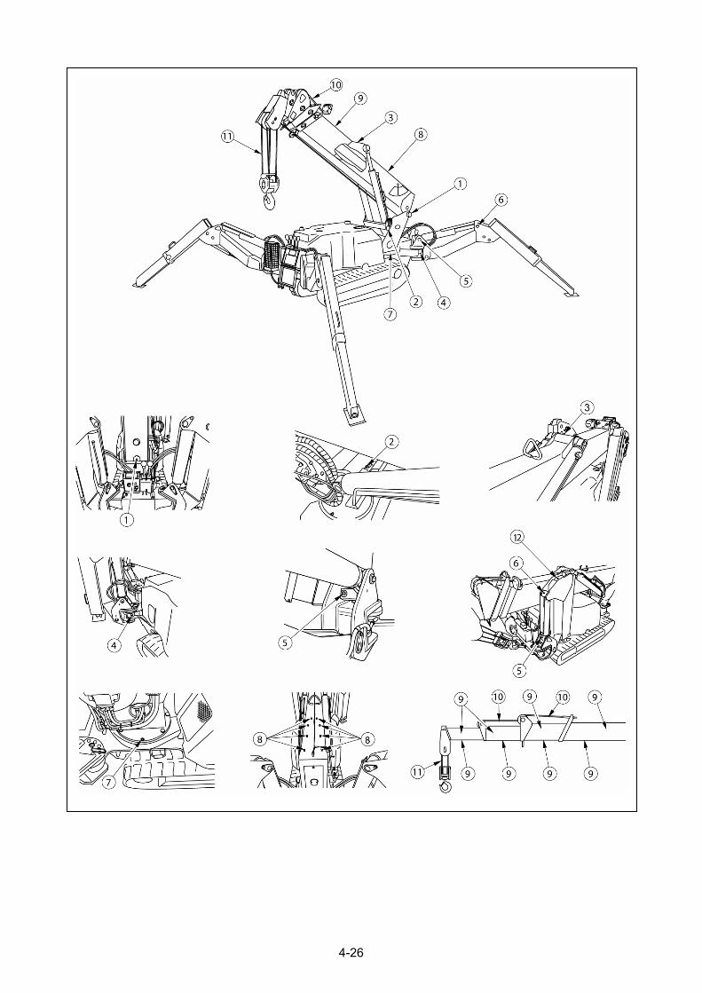
4-26
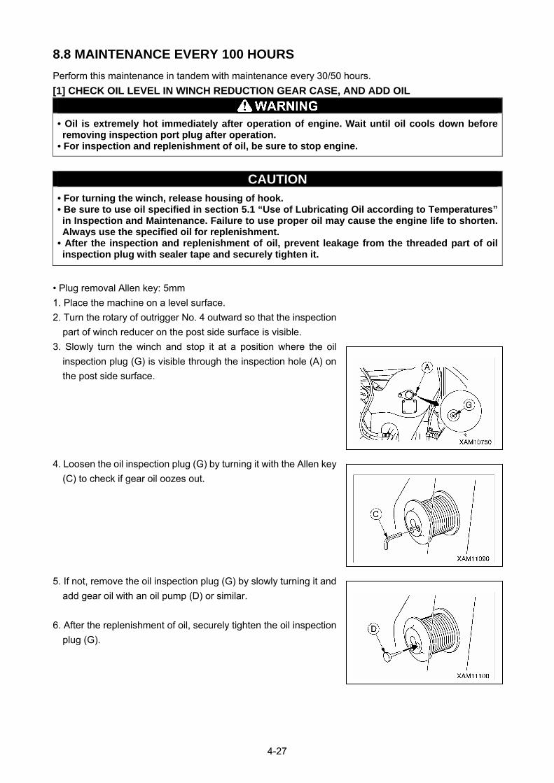
4-27
8.8 MAINTENANCE EVERY 100 HOURS
Perform this maintenance in tandem with maintenance every 30/50 hours.
[1] CHECK OIL LEVEL IN WINCH REDUCTION GEAR CASE, AND ADD OIL
• Oil is extremely hot immediately after operation of engine. Wait until oil cools down before removing inspection port plug after operation.
• For inspection and replenishment of oil, be sure to stop engine.
CAUTION • For turning the winch, release housing of hook. • Be sure to use oil specified in section 5.1 “Use of Lubricating Oil according to Temperatures” in Inspection and Maintenance. Failure to use proper oil may cause the engine life to shorten. Always use the specified oil for replenishment.
• After the inspection and replenishment of oil, prevent leakage from the threaded part of oil inspection plug with sealer tape and securely tighten it.
• Plug removal Allen key: 5mm
1. Place the machine on a level surface.
2. Turn the rotary of outrigger No. 4 outward so that the inspection
part of winch reducer on the post side surface is visible.
3. Slowly turn the winch and stop it at a position where the oil
inspection plug (G) is visible through the inspection hole (A) on
the post side surface.
4. Loosen the oil inspection plug (G) by turning it with the Allen key
(C) to check if gear oil oozes out.
5. If not, remove the oil inspection plug (G) by slowly turning it and
add gear oil with an oil pump (D) or similar.
6. After the replenishment of oil, securely tighten the oil inspection
plug (G).
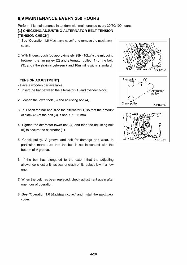
4-28
8.9 MAINTENANCE EVERY 250 HOURS
Perform this maintenance in tandem with maintenance every 30/50/100 hours.
[1] CHECKING/ADJUSTING ALTERNATOR BELT TENSION
[TENSION CHECK]
1. See “Operation 1.6 Machinery cover” and remove the machinery cover.
2. With fingers, push (by approximately 98N {10kgf}) the midpoint
between the fan pulley (2) and alternator pulley (1) of the belt
(3), and if the strain is between 7 and 10mm it is within standard.
[TENSION ADJUSTMENT]
• Have a wooden bar available.
1. Insert the bar between the alternator (1) and cylinder block.
2. Loosen the lower bolt (5) and adjusting bolt (4).
3. Pull back the bar and slide the alternator (1) so that the amount
of slack (A) of the belt (3) is about 7 – 10mm.
4. Tighten the alternator lower bolt (4) and then the adjusting bolt
(5) to secure the alternator (1).
5. Check pulley, V groove and belt for damage and wear. In
particular, make sure that the belt is not in contact with the
bottom of V groove.
6. If the belt has elongated to the extent that the adjusting
allowance is lost or it has scar or crack on it, replace it with a new
one.
7. When the belt has been replaced, check adjustment again after
one hour of operation.
8. See “Operation 1.6 Machinery cover” and install the machinery cover.
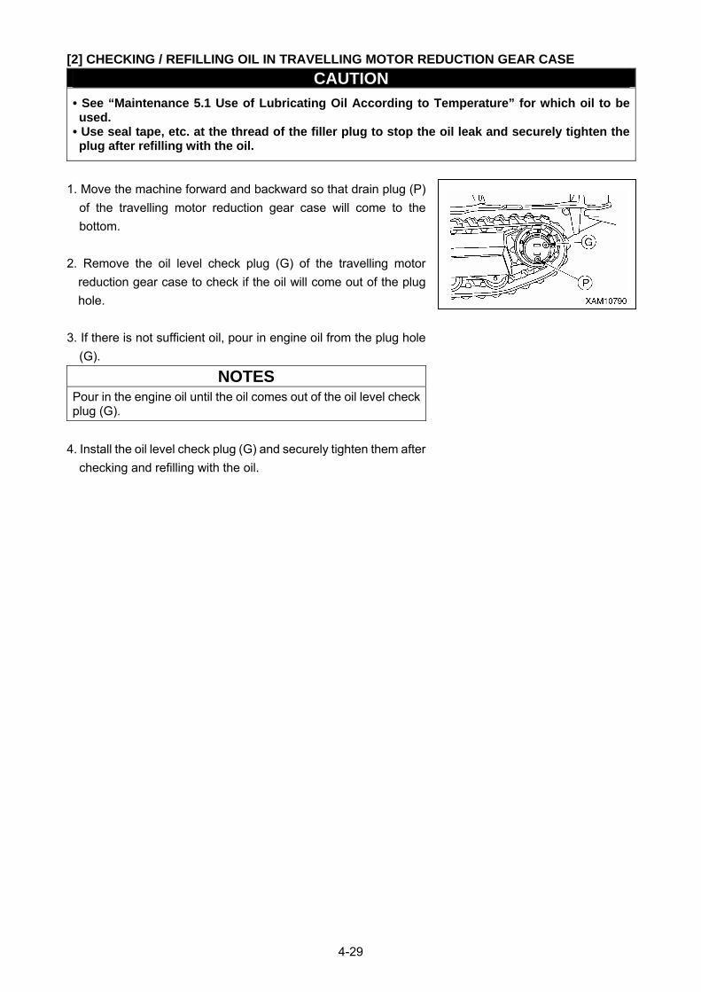
4-29
[2] CHECKING / REFILLING OIL IN TRAVELLING MOTOR REDUCTION GEAR CASE
CAUTION
• See “Maintenance 5.1 Use of Lubricating Oil According to Temperature” for which oil to be used.
• Use seal tape, etc. at the thread of the filler plug to stop the oil leak and securely tighten the plug after refilling with the oil.
1. Move the machine forward and backward so that drain plug (P)
of the travelling motor reduction gear case will come to the
bottom.
2. Remove the oil level check plug (G) of the travelling motor
reduction gear case to check if the oil will come out of the plug
hole.
3. If there is not sufficient oil, pour in engine oil from the plug hole
(G).
NOTES
Pour in the engine oil until the oil comes out of the oil level check plug (G).
4. Install the oil level check plug (G) and securely tighten them after
checking and refilling with the oil.
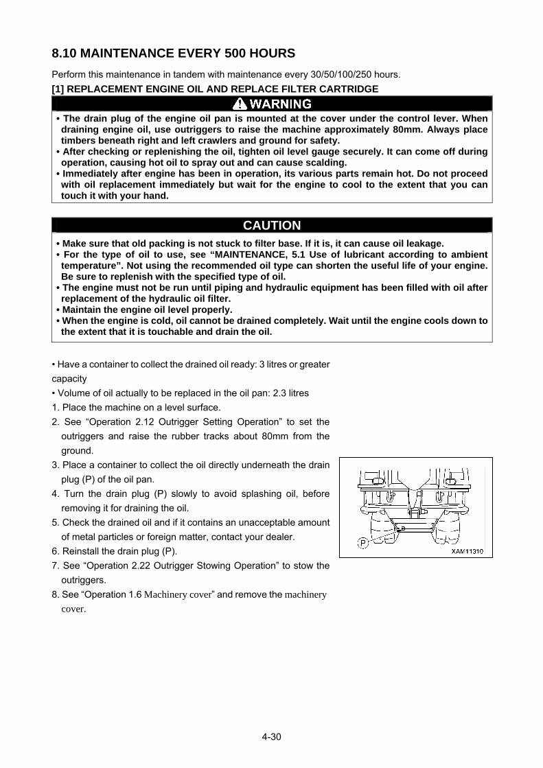
4-30
8.10 MAINTENANCE EVERY 500 HOURS
Perform this maintenance in tandem with maintenance every 30/50/100/250 hours.
[1] REPLACEMENT ENGINE OIL AND REPLACE FILTER CARTRIDGE
• The drain plug of the engine oil pan is mounted at the cover under the control lever. When draining engine oil, use outriggers to raise the machine approximately 80mm. Always place timbers beneath right and left crawlers and ground for safety.
• After checking or replenishing the oil, tighten oil level gauge securely. It can come off during operation, causing hot oil to spray out and can cause scalding.
• Immediately after engine has been in operation, its various parts remain hot. Do not proceed with oil replacement immediately but wait for the engine to cool to the extent that you can touch it with your hand.
CAUTION • Make sure that old packing is not stuck to filter base. If it is, it can cause oil leakage. • For the type of oil to use, see “MAINTENANCE, 5.1 Use of lubricant according to ambient temperature”. Not using the recommended oil type can shorten the useful life of your engine. Be sure to replenish with the specified type of oil.
• The engine must not be run until piping and hydraulic equipment has been filled with oil after replacement of the hydraulic oil filter.
• Maintain the engine oil level properly. • When the engine is cold, oil cannot be drained completely. Wait until the engine cools down to the extent that it is touchable and drain the oil.
• Have a container to collect the drained oil ready: 3 litres or greater
capacity
• Volume of oil actually to be replaced in the oil pan: 2.3 litres
1. Place the machine on a level surface.
2. See “Operation 2.12 Outrigger Setting Operation” to set the
outriggers and raise the rubber tracks about 80mm from the
ground.
3. Place a container to collect the oil directly underneath the drain
plug (P) of the oil pan.
4. Turn the drain plug (P) slowly to avoid splashing oil, before
removing it for draining the oil.
5. Check the drained oil and if it contains an unacceptable amount
of metal particles or foreign matter, contact your dealer. 6. Reinstall the drain plug (P).
7. See “Operation 2.22 Outrigger Stowing Operation” to stow the
outriggers.
8. See “Operation 1.6 Machinery cover” and remove the machinery cover.
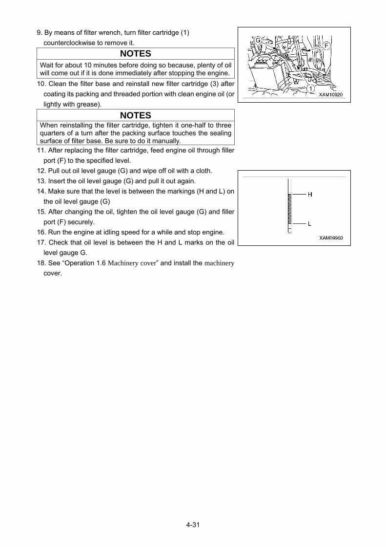
4-31
9. By means of filter wrench, turn filter cartridge (1)
counterclockwise to remove it.
NOTES
Wait for about 10 minutes before doing so because, plenty of oil will come out if it is done immediately after stopping the engine.
10. Clean the filter base and reinstall new filter cartridge (3) after
coating its packing and threaded portion with clean engine oil (or
lightly with grease).
NOTES When reinstalling the filter cartridge, tighten it one-half to three quarters of a turn after the packing surface touches the sealing surface of filter base. Be sure to do it manually.
11. After replacing the filter cartridge, feed engine oil through filler
port (F) to the specified level.
12. Pull out oil level gauge (G) and wipe off oil with a cloth.
13. Insert the oil level gauge (G) and pull it out again.
14. Make sure that the level is between the markings (H and L) on
the oil level gauge (G)
15. After changing the oil, tighten the oil level gauge (G) and filler
port (F) securely.
16. Run the engine at idling speed for a while and stop engine.
17. Check that oil level is between the H and L marks on the oil
level gauge G.
18. See “Operation 1.6 Machinery cover” and install the machinery cover.
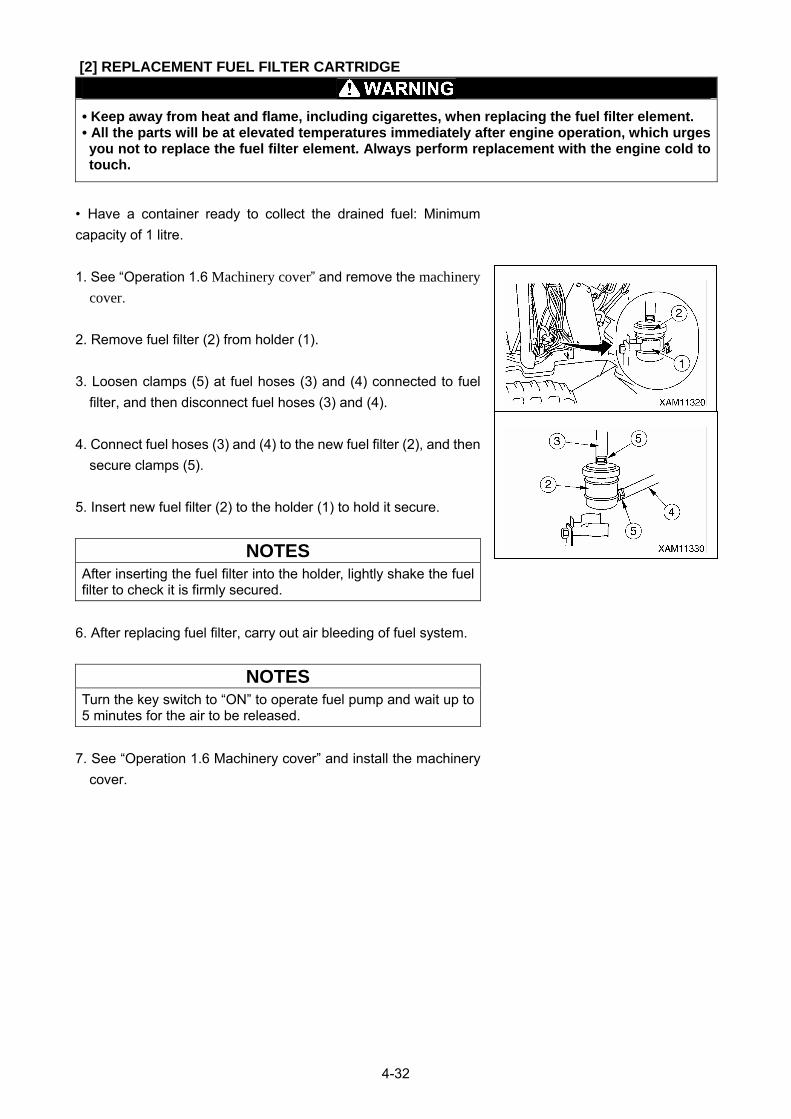
4-32
[2] REPLACEMENT FUEL FILTER CARTRIDGE
• Keep away from heat and flame, including cigarettes, when replacing the fuel filter element. • All the parts will be at elevated temperatures immediately after engine operation, which urges you not to replace the fuel filter element. Always perform replacement with the engine cold to touch.
• Have a container ready to collect the drained fuel: Minimum
capacity of 1 litre.
1. See “Operation 1.6 Machinery cover” and remove the machinery cover.
2. Remove fuel filter (2) from holder (1).
3. Loosen clamps (5) at fuel hoses (3) and (4) connected to fuel
filter, and then disconnect fuel hoses (3) and (4).
4. Connect fuel hoses (3) and (4) to the new fuel filter (2), and then
secure clamps (5).
5. Insert new fuel filter (2) to the holder (1) to hold it secure.
NOTES
After inserting the fuel filter into the holder, lightly shake the fuel filter to check it is firmly secured.
6. After replacing fuel filter, carry out air bleeding of fuel system.
NOTES
Turn the key switch to “ON” to operate fuel pump and wait up to 5 minutes for the air to be released.
7. See “Operation 1.6 Machinery cover” and install the machinery
cover.
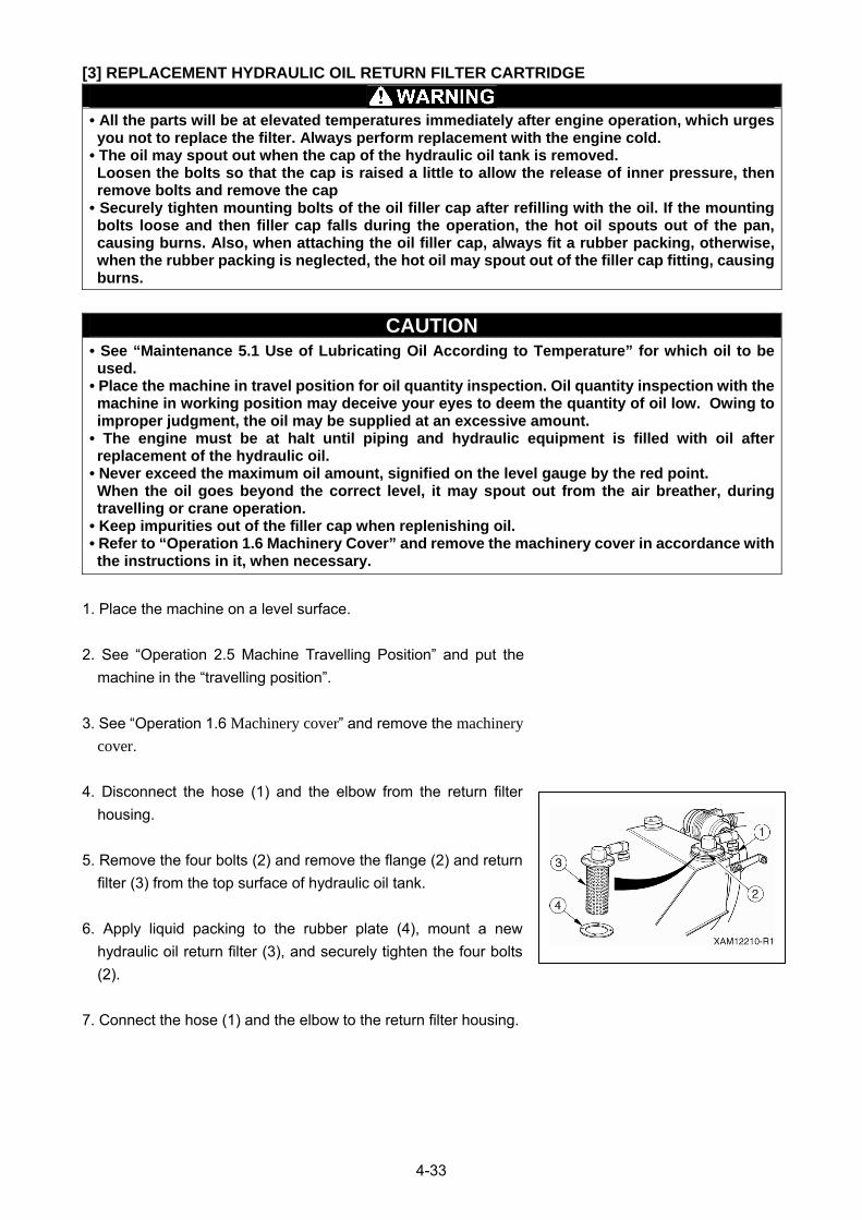
4-33
[3] REPLACEMENT HYDRAULIC OIL RETURN FILTER CARTRIDGE
• All the parts will be at elevated temperatures immediately after engine operation, which urges you not to replace the filter. Always perform replacement with the engine cold.
• The oil may spout out when the cap of the hydraulic oil tank is removed. Loosen the bolts so that the cap is raised a little to allow the release of inner pressure, then remove bolts and remove the cap
• Securely tighten mounting bolts of the oil filler cap after refilling with the oil. If the mounting bolts loose and then filler cap falls during the operation, the hot oil spouts out of the pan, causing burns. Also, when attaching the oil filler cap, always fit a rubber packing, otherwise, when the rubber packing is neglected, the hot oil may spout out of the filler cap fitting, causing burns.
CAUTION • See “Maintenance 5.1 Use of Lubricating Oil According to Temperature” for which oil to be used.
• Place the machine in travel position for oil quantity inspection. Oil quantity inspection with the machine in working position may deceive your eyes to deem the quantity of oil low. Owing to improper judgment, the oil may be supplied at an excessive amount.
• The engine must be at halt until piping and hydraulic equipment is filled with oil after replacement of the hydraulic oil.
• Never exceed the maximum oil amount, signified on the level gauge by the red point. When the oil goes beyond the correct level, it may spout out from the air breather, during travelling or crane operation.
• Keep impurities out of the filler cap when replenishing oil. • Refer to “Operation 1.6 Machinery Cover” and remove the machinery cover in accordance with the instructions in it, when necessary.
1. Place the machine on a level surface.
2. See “Operation 2.5 Machine Travelling Position” and put the
machine in the “travelling position”.
3. See “Operation 1.6 Machinery cover” and remove the machinery cover.
4. Disconnect the hose (1) and the elbow from the return filter
housing.
5. Remove the four bolts (2) and remove the flange (2) and return
filter (3) from the top surface of hydraulic oil tank.
6. Apply liquid packing to the rubber plate (4), mount a new
hydraulic oil return filter (3), and securely tighten the four bolts
(2).
7. Connect the hose (1) and the elbow to the return filter housing.
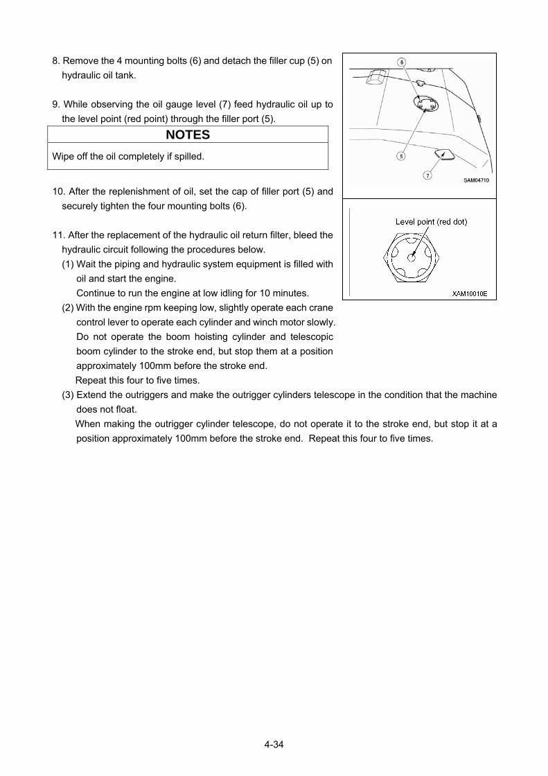
4-34
8. Remove the 4 mounting bolts (6) and detach the filler cup (5) on
hydraulic oil tank.
9. While observing the oil gauge level (7) feed hydraulic oil up to
the level point (red point) through the filler port (5).
10. After the replenishment of oil, set the cap of filler port (5) and
securely tighten the four mounting bolts (6).
11. After the replacement of the hydraulic oil return filter, bleed the
hydraulic circuit following the procedures below.
(1) Wait the piping and hydraulic system equipment is filled with
oil and start the engine.
Continue to run the engine at low idling for 10 minutes.
(2) With the engine rpm keeping low, slightly operate each crane
control lever to operate each cylinder and winch motor slowly.
Do not operate the boom hoisting cylinder and telescopic
boom cylinder to the stroke end, but stop them at a position
approximately 100mm before the stroke end.
Repeat this four to five times.
(3) Extend the outriggers and make the outrigger cylinders telescope in the condition that the machine
does not float.
When making the outrigger cylinder telescope, do not operate it to the stroke end, but stop it at a
position approximately 100mm before the stroke end. Repeat this four to five times.
NOTES
Wipe off the oil completely if spilled.
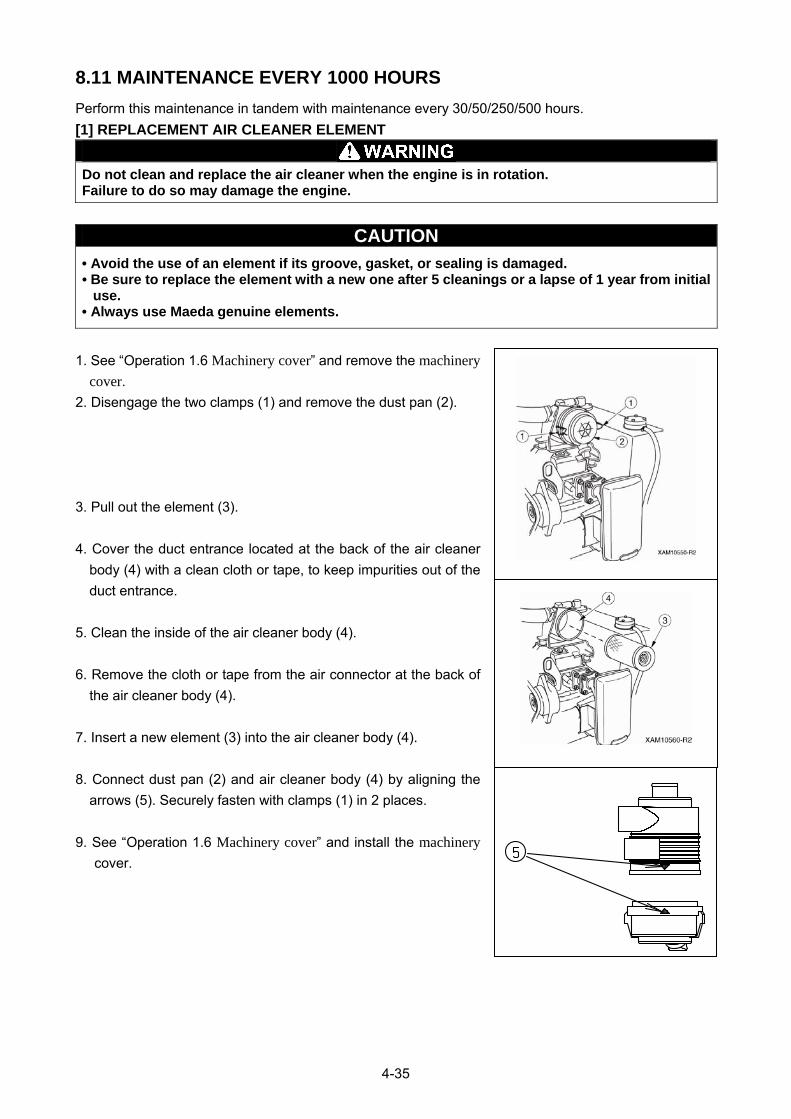
4-35
8.11 MAINTENANCE EVERY 1000 HOURS
Perform this maintenance in tandem with maintenance every 30/50/250/500 hours.
[1] REPLACEMENT AIR CLEANER ELEMENT
Do not clean and replace the air cleaner when the engine is in rotation. Failure to do so may damage the engine.
CAUTION
• Avoid the use of an element if its groove, gasket, or sealing is damaged. • Be sure to replace the element with a new one after 5 cleanings or a lapse of 1 year from initial use.
• Always use Maeda genuine elements.
1. See “Operation 1.6 Machinery cover” and remove the machinery cover.
2. Disengage the two clamps (1) and remove the dust pan (2).
3. Pull out the element (3).
4. Cover the duct entrance located at the back of the air cleaner
body (4) with a clean cloth or tape, to keep impurities out of the
duct entrance.
5. Clean the inside of the air cleaner body (4).
6. Remove the cloth or tape from the air connector at the back of
the air cleaner body (4).
7. Insert a new element (3) into the air cleaner body (4).
8. Connect dust pan (2) and air cleaner body (4) by aligning the
arrows (5). Securely fasten with clamps (1) in 2 places.
9. See “Operation 1.6 Machinery cover” and install the machinery cover.
4-36
[2] CLEANING ENGINE COOLING SYSTEM
• Coolant will be at elevated temperatures immediately after engine operation, which urges you not to drain coolant. Always perform coolant draining with the engine cold.
• Do not remove the radiator cap if radiator coolant is hot. Potential gush of boiling water may occur if disregarded. Cap removal is allowed when the water drops in temperature. Be sure to relieve internal pressure by slowly rotating the filler cap before cap removal.
• Do not stand in front of and behind the machine when starting the engine for cooling system cleaning. Failure to stand aside of the machine may pose a danger in the event of a sudden movement of the machine.
• Keep antifreeze away from flame. Antifreeze is a flammable solution. Do not smoke when handling antifreeze.
CAUTION
• Always use tap water for coolant. Contact us or our sales service agency if river water, well water, or water through the small water-supply system is necessarily substituted for tap water.
• A mixing ratio of antifreeze is to be controlled by the concentration meter.
Cooling system cleaning and antifreeze replacement should conform to the cycles specified in the
following table.
Antifreeze type Cooling system cleaning and antifreeze replacement
Anti-corrosive all-season type Every other year (in fall) or every 4000 hours, whichever falls first
All-season type Every year (in fall) or 2000 hours, whichever comes first
One winter season type Biannually (spring and fall).
Perform cooling system cleaning and antifreeze replacement with the machine in a horizontal position.
A mixing ratio of antifreeze varies with temperature. Antifreeze as a volume ratio is min. 30% to yield
anticorrosive effect.
The mixing ratio between water and antifreeze is to be determined with respect to past minimum
temperatures, in accordance with “Mixing ratio between water and antifreeze” shown below. For actual
mixing, set temperature 10 degrees lower than minimum temperature.
[MIXING RATIO BETWEEN WATER AND ANTIFREEZE:YANMAR COOLANT] Min. temperature (°C)
Mixed quantity (L)
Min. -15 -20 -24 -29
Antifreeze 0.6 0.7 0.8 0.9
Water 1.5 1.4 1.3 1.2
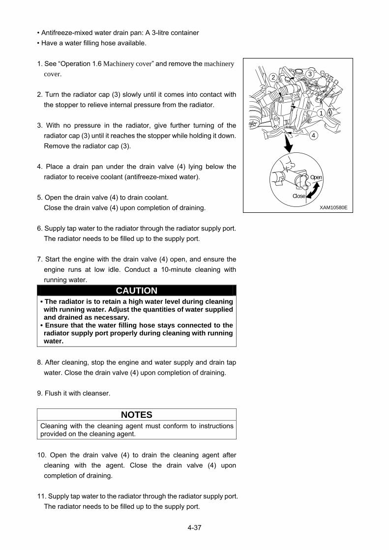
4-37
• Antifreeze-mixed water drain pan: A 3-litre container
• Have a water filling hose available.
1. See “Operation 1.6 Machinery cover” and remove the machinery cover.
2. Turn the radiator cap (3) slowly until it comes into contact with
the stopper to relieve internal pressure from the radiator.
3. With no pressure in the radiator, give further turning of the
radiator cap (3) until it reaches the stopper while holding it down.
Remove the radiator cap (3).
4. Place a drain pan under the drain valve (4) lying below the
radiator to receive coolant (antifreeze-mixed water).
5. Open the drain valve (4) to drain coolant.
Close the drain valve (4) upon completion of draining.
6. Supply tap water to the radiator through the radiator supply port.
The radiator needs to be filled up to the supply port.
7. Start the engine with the drain valve (4) open, and ensure the
engine runs at low idle. Conduct a 10-minute cleaning with
running water.
CAUTION • The radiator is to retain a high water level during cleaning with running water. Adjust the quantities of water supplied and drained as necessary.
• Ensure that the water filling hose stays connected to the radiator supply port properly during cleaning with running water.
8. After cleaning, stop the engine and water supply and drain tap
water. Close the drain valve (4) upon completion of draining.
9. Flush it with cleanser.
NOTES
Cleaning with the cleaning agent must conform to instructions provided on the cleaning agent.
10. Open the drain valve (4) to drain the cleaning agent after
cleaning with the agent. Close the drain valve (4) upon
completion of draining.
11. Supply tap water to the radiator through the radiator supply port.
The radiator needs to be filled up to the supply port.
1
32
4
XAM10580E
Close
Open
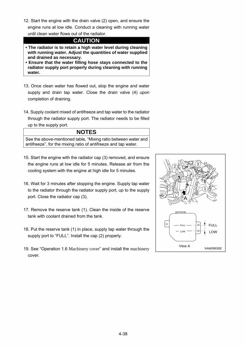
4-38
12. Start the engine with the drain valve (2) open, and ensure the
engine runs at low idle. Conduct a cleaning with running water
until clean water flows out of the radiator.
CAUTION • The radiator is to retain a high water level during cleaning with running water. Adjust the quantities of water supplied and drained as necessary.
• Ensure that the water filling hose stays connected to the radiator supply port properly during cleaning with running water.
13. Once clean water has flowed out, stop the engine and water
supply and drain tap water. Close the drain valve (4) upon
completion of draining.
14. Supply coolant mixed of antifreeze and tap water to the radiator
through the radiator supply port. The radiator needs to be filled
up to the supply port.
NOTES
See the above-mentioned table, “Mixing ratio between water and antifreeze”, for the mixing ratio of antifreeze and tap water.
15. Start the engine with the radiator cap (3) removed, and ensure
the engine runs at low idle for 5 minutes. Release air from the
cooling system with the engine at high idle for 5 minutes.
16. Wait for 3 minutes after stopping the engine. Supply tap water
to the radiator through the radiator supply port, up to the supply
port. Close the radiator cap (3).
17. Remove the reserve tank (1). Clean the inside of the reserve
tank with coolant drained from the tank.
18. Put the reserve tank (1) in place, supply tap water through the
supply port to “FULL”. Install the cap (2) properly.
19. See “Operation 1.6 Machinery cover” and install the machinery cover.
1
32
FULLFULL
LOW
View A
LOW
XAM09930E
A
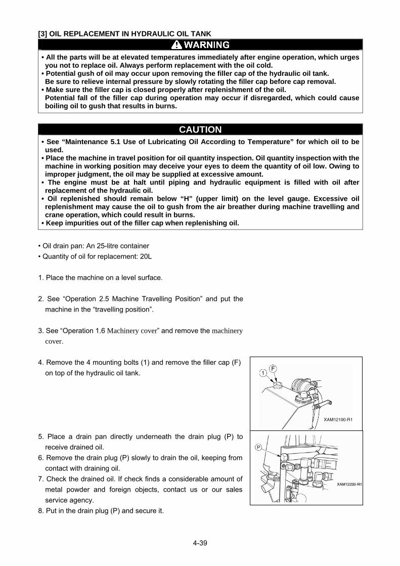
4-39
[3] OIL REPLACEMENT IN HYDRAULIC OIL TANK
• All the parts will be at elevated temperatures immediately after engine operation, which urges you not to replace oil. Always perform replacement with the oil cold.
• Potential gush of oil may occur upon removing the filler cap of the hydraulic oil tank. Be sure to relieve internal pressure by slowly rotating the filler cap before cap removal.
• Make sure the filler cap is closed properly after replenishment of the oil. Potential fall of the filler cap during operation may occur if disregarded, which could cause boiling oil to gush that results in burns.
CAUTION • See “Maintenance 5.1 Use of Lubricating Oil According to Temperature” for which oil to be used.
• Place the machine in travel position for oil quantity inspection. Oil quantity inspection with the machine in working position may deceive your eyes to deem the quantity of oil low. Owing to improper judgment, the oil may be supplied at excessive amount.
• The engine must be at halt until piping and hydraulic equipment is filled with oil after replacement of the hydraulic oil.
• Oil replenished should remain below “H” (upper limit) on the level gauge. Excessive oil replenishment may cause the oil to gush from the air breather during machine travelling and crane operation, which could result in burns.
• Keep impurities out of the filler cap when replenishing oil.
• Oil drain pan: An 25-litre container
• Quantity of oil for replacement: 20L
1. Place the machine on a level surface.
2. See “Operation 2.5 Machine Travelling Position” and put the
machine in the “travelling position”.
3. See “Operation 1.6 Machinery cover” and remove the machinery cover.
4. Remove the 4 mounting bolts (1) and remove the filler cap (F)
on top of the hydraulic oil tank.
5. Place a drain pan directly underneath the drain plug (P) to
receive drained oil.
6. Remove the drain plug (P) slowly to drain the oil, keeping from
contact with draining oil.
7. Check the drained oil. If check finds a considerable amount of
metal powder and foreign objects, contact us or our sales
service agency.
8. Put in the drain plug (P) and secure it.
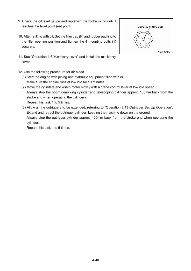
4-40
9. Check the oil level gauge and replenish the hydraulic oil until it
reaches the level point (red point).
10. After refilling with oil, Set the filler cap (F) and rubber packing to
the filler opening position and tighten the 4 mounting bolts (1)
securely.
11. See “Operation 1.6 Machinery cover” and install the machinery cover.
12. Use the following procedure for air bleed.
(1) Start the engine with piping and hydraulic equipment filled with oil.
Make sure the engine runs at low idle for 10 minutes.
(2) Move the cylinders and winch motor slowly with a crane control lever at low idle speed.
Always stop the boom derricking cylinder and telescoping cylinder approx. 100mm back from the
stroke end when operating the cylinders.
Repeat this task 4 to 5 times.
(3) Allow all the outriggers to be extended, referring to “Operation 2.13 Outrigger Set Up Operation”.
Extend and retract the outrigger cylinder, keeping the machine down on the ground.
Always stop the outrigger cylinder approx. 100mm back from the stroke end when operating the
cylinder.
Repeat this task 4 to 5 times.
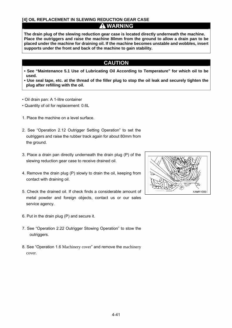
4-41
[4] OIL REPLACEMENT IN SLEWING REDUCTION GEAR CASE
The drain plug of the slewing reduction gear case is located directly underneath the machine. Place the outriggers and raise the machine 80mm from the ground to allow a drain pan to be placed under the machine for draining oil. If the machine becomes unstable and wobbles, insert supports under the front and back of the machine to gain stability.
CAUTION
• See “Maintenance 5.1 Use of Lubricating Oil According to Temperature” for which oil to be used.
• Use seal tape, etc. at the thread of the filler plug to stop the oil leak and securely tighten the plug after refilling with the oil.
• Oil drain pan: A 1-litre container
• Quantity of oil for replacement: 0.6L
1. Place the machine on a level surface.
2. See “Operation 2.12 Outrigger Setting Operation” to set the
outriggers and raise the rubber track again for about 80mm from
the ground.
3. Place a drain pan directly underneath the drain plug (P) of the
slewing reduction gear case to receive drained oil.
4. Remove the drain plug (P) slowly to drain the oil, keeping from
contact with draining oil.
5. Check the drained oil. If check finds a considerable amount of
metal powder and foreign objects, contact us or our sales
service agency.
6. Put in the drain plug (P) and secure it.
7. See “Operation 2.22 Outrigger Stowing Operation” to stow the
outriggers.
8. See “Operation 1.6 Machinery cover” and remove the machinery cover.

4-42
9. Remove the filler plug (F) at slewing reduction gear case. Fill w
ith gear oil from the plug hole up to the middle of the gear case.
NOTES The height at middle of gear case is 50 mm from the top of the filler plug. 50mm (±5mm) is the appropriate oil level. Do not allow ingress of dust or dirt when measuring or filling oil.
10. Put in the filler plug (F) and secure it after oil replacement.
11. See “Operation 1.6 Machinery cover” and install the machinery cover.
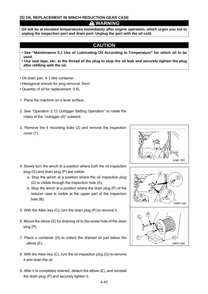
4-43
[5] OIL REPLACEMENT IN WINCH REDUCTION GEAR CASE
Oil will be at elevated temperatures immediately after engine operation, which urges you not to unplug the inspection port and drain port. Unplug the port with the oil cold.
CAUTION
• See “Maintenance 5.1 Use of Lubricating Oil According to Temperature” for which oil to be used.
• Use seal tape, etc. at the thread of the plug to stop the oil leak and securely tighten the plug after refilling with the oil.
• Oil drain pan: A 1-litre container
• Hexagonal wrench for plug removal: 5mm
• Quantity of oil for replacement: 0.5L
1. Place the machine on a level surface.
2. See “Operation 2.12 Outrigger Setting Operation” to rotate the
rotary of the “outrigger (4)” outward.
3. Remove the 4 mounting bolts (2) and remove the inspection
cover (1).
4. Slowly turn the winch to a position where both the oil inspection
plug (G) and drain plug (P) are visible.
a. Stop the winch at a position where the oil inspection plug
(G) is visible through the inspection hole (A).
b. Stop the winch at a position where the drain plug (P) of the
reducer case is visible at the upper part of the inspection
hole (B).
5. With the Allen key (C); turn the drain plug (P) to remove it.
6. Mount the elbow (E) for draining oil to the screw hole of the drain
plug (P).
7. Place a container (H) to collect the drained oil just below the
elbow (E).
8. With the Allen key (C), turn the oil inspection plug (G) to remove
it and drain the oil.
9. After it is completely drained, detach the elbow (E), and reinstall
the drain plug (P) and securely tighten it.
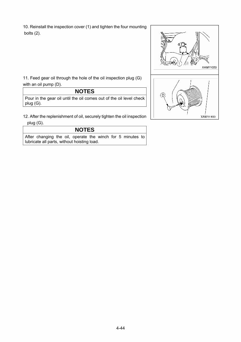
4-44
10. Reinstall the inspection cover (1) and tighten the four mounting
bolts (2).
11. Feed gear oil through the hole of the oil inspection plug (G)
with an oil pump (D).
NOTES
Pour in the gear oil until the oil comes out of the oil level check plug (G).
12. After the replenishment of oil, securely tighten the oil inspection
plug (G).
NOTES
After changing the oil, operate the winch for 5 minutes to lubricate all parts, without hoisting load.
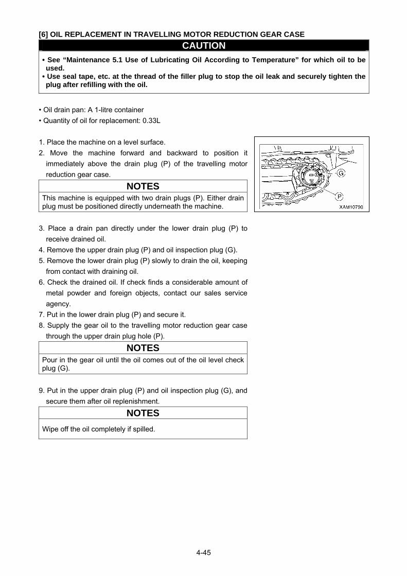
4-45
[6] OIL REPLACEMENT IN TRAVELLING MOTOR REDUCTION GEAR CASE
CAUTION
• See “Maintenance 5.1 Use of Lubricating Oil According to Temperature” for which oil to be used.
• Use seal tape, etc. at the thread of the filler plug to stop the oil leak and securely tighten the plug after refilling with the oil.
• Oil drain pan: A 1-litre container
• Quantity of oil for replacement: 0.33L
1. Place the machine on a level surface.
2. Move the machine forward and backward to position it
immediately above the drain plug (P) of the travelling motor
reduction gear case.
NOTES
This machine is equipped with two drain plugs (P). Either drain plug must be positioned directly underneath the machine.
3. Place a drain pan directly under the lower drain plug (P) to
receive drained oil.
4. Remove the upper drain plug (P) and oil inspection plug (G).
5. Remove the lower drain plug (P) slowly to drain the oil, keeping
from contact with draining oil.
6. Check the drained oil. If check finds a considerable amount of
metal powder and foreign objects, contact our sales service
agency.
7. Put in the lower drain plug (P) and secure it.
8. Supply the gear oil to the travelling motor reduction gear case
through the upper drain plug hole (P).
NOTES
Pour in the gear oil until the oil comes out of the oil level check plug (G).
9. Put in the upper drain plug (P) and oil inspection plug (G), and
secure them after oil replenishment.
NOTES
Wipe off the oil completely if spilled.

4-46
8.12 MAINTENANCE EVERY 2000 HOURS
Perform this maintenance in tandem with maintenance every 30/50/250/500/1000 hours.
[1] INSPECTION/ADJUSTMENT ENGINE VALVE CLEARANCE
Inspection and adjustment of valve clearance require special tools.
Contact us or our sales service agency to request inspection and repair.
[2] CHECKING ALTERNATOR AND STARTER
CAUTION
Inspection every 1000 hours is recommended in case of frequent engine starting.
There may be a wearing down of the brush and insufficient grease.
Contact us or our sales service agency to request inspection and repair.

SPECIFICATIONS
1. SPECIFICATIONS 5-2
2. SPECIFICATION DIMENSIONAL DRAWING 5-3
3. DIMENSIONAL DRAWING OF OUTRIGGER WIDTH 5-4
4. RATED TOTAL LOAD CHART 5-5
5. WORKING RANGE AND LIFTING HEIGHT 5-8
5-1

1. SPECIFICATIONS
MC285C-2
Machine weight 1960kg Overall length width height
2750mm x 750mm x 1470mm
Distance between center idler and sprocket
975mm
Track gauge 550mm
Weight and dimensions
Width of crawler 200mm Crane capacity 2.82t x 1.4m Maximum working radius 8.2m Performanc
e Maximum lifting height above ground
8.7m
Type Hydraulic motor driven with brake, differential planetary gear type, with counter balance valve(within drum type)
Hook hoist speed 9.3 m/min (4 layers, 4 parts of line) Winch system
Hoist wire rope IWRC 6 x Fi (29) 7 mm x 48 m
Type Sequential hydraulic cylinders × 2 + wire rope telescoping systems × 2
Type of boom Fully automatic 5-section pentagonal telescopic
(3 to 5 stage: simultaneous telescoping) Boom length 2.535m – 4.075m – 5.575m – 7.075m – 8.575m
Telescoping system
Boom telescoping stroke/ time
6.04 m/22 sec
Type Hydraulic double acting cylinder,direct acting type × 2 Boom hoist system Derricking angle/ time 0 to 80° /14 sec
Type Swing bearing support, hydraulic motor drive, worm and spur gears, worm self-lock
Slewing system
Slewing angle/ speed 360° (continuous)/60 sec (1.0 RPM)
Type 1st stage with flexible stay damper, 2nd stage manual pullout, hydraulic cylinder direct acting type Outrigger
system Max extended width (Front) 3810mm x (Right/left) 4580mm x (Rear) 4530mm
Type Hydraulic motor driven, Step-less speed changer
Travel speed Forward/backward: 0 – 2.2 km/h Grade ability 20°
Travel system
Ground pressure 49.3 kPa(0.497kgf/c㎡)
Hydraulic pump variable piston pump
Rated pressure 20.6MPa (210kgf/cm2) Hydraulic system
Hydraulic oil tank capacity 20L Model Yanmar 2TNV70-NMBA Type In-line 2-cylinder, water cooled, 4-cycle diesel Displacement 0.569L (569cc) Rated output (continuous) 7.4kW/2500min-1 (10.1PS/2500rpm)
Engine
Fuel tank capacity Diesel 12L Battery Model 55B24R (DC12V x 1 piece)
Safety device
Over hoist detector, over un-winding detector, angle indicator, hydraulic safety valve, wire rope latch, level, machine body inclination alarm, EMO Switch, crane outrigger interlock device, moment limiter, outrigger setting light, working status light
5-2
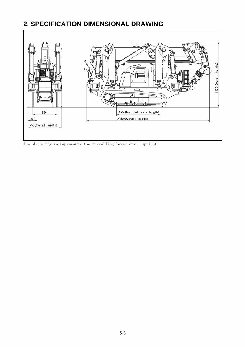
2. SPECIFICATION DIMENSIONAL DRAWING
The above figure represents the travelling lever stand upright.
5-3
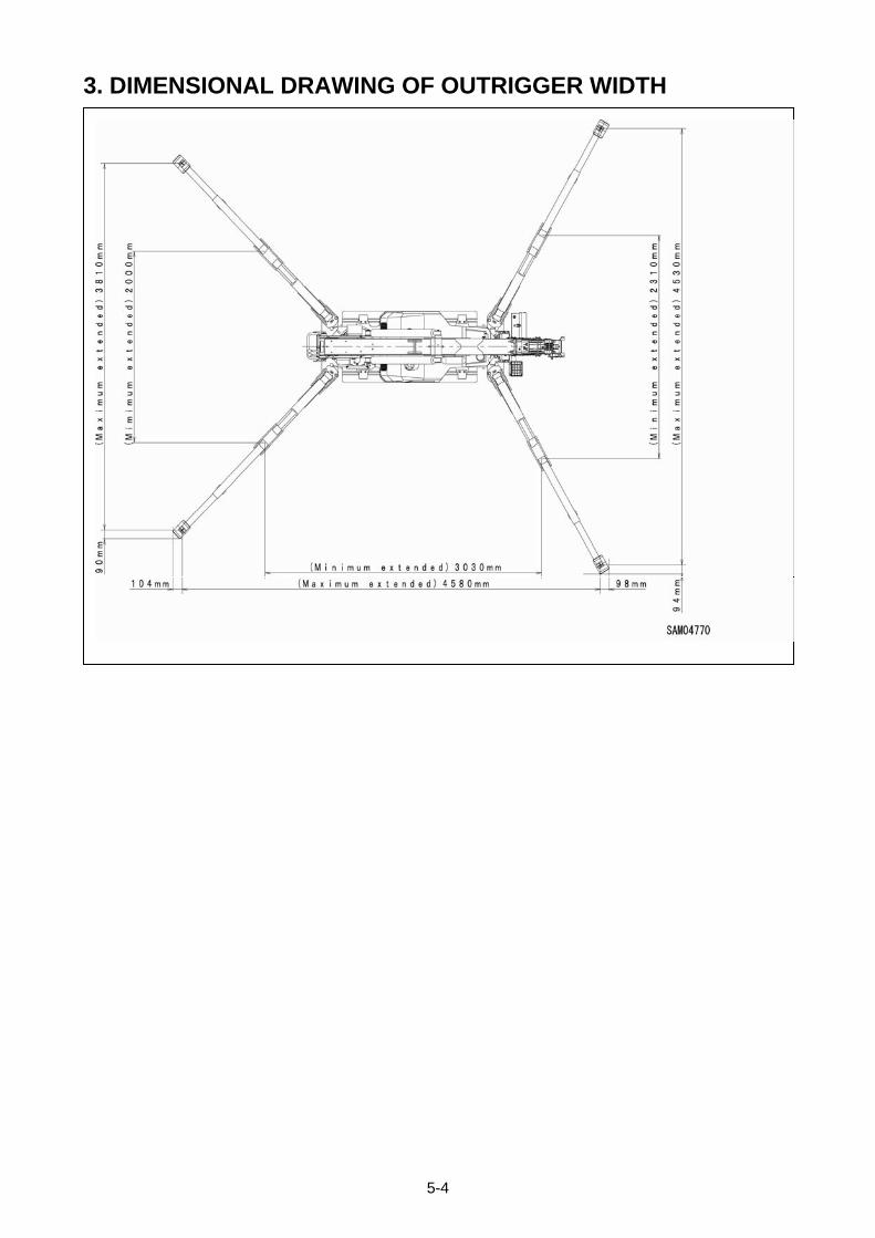
3. DIMENSIONAL DRAWING OF OUTRIGGER WIDTH
5-4
4. RATED TOTAL LOAD CHART The Rated total load Chart is based on actual working radius with the bending of boom attributable to
load reflected and is shown with the mass of hook block (30kg) included.
4.1 RATED TOTAL LOAD CHART FOR 4 FALLS
OUTRIGGER EXTENDED TO MAXIMUM
2.535m/4.075m BOOM 5.575m BOOM 7.075m BOOM 8.575m BOOM
Working radius (m)
Rated total load (kg)
Working radius (m)
Rated total load (kg)
Working radius (m)
Rated total load (kg)
Working radius (m)
Rated total load (kg)
1.4 or less 2820 3.0 or less 1220 3.6 or less 820 4.0 or less 550
1.50 2520 3.50 970 4.00 740 4.50 400
2.00 1920 4.00 780 4.50 580 5.00 340
2.50 1570 4.50 630 5.00 480 5.50 300
3.00 1220 5.00 530 5.50 430 6.00 270
3.50 970 5.205 530 6.00 380 6.50 230
3.705 920 -- -- 6.50 350 7.00 200
-- -- -- -- 6.705 330 7.50 180
-- -- -- -- -- -- 8.00 150
-- -- -- -- -- -- 8.205 150
OUTRIGGER EXTENDED TO OTHER THAN MAXIMUM
2.535m/4.075m BOOM 5.575m BOOM 7.075m BOOM 8.575m BOOM
Working radius (m)
Rated total load (kg)
Working radius (m)
Rated total load (kg)
Working radius (m)
Rated total load (kg)
Working radius (m)
Rated total load (kg)
1.5 or less 1720 3.0 or less 510 3.6 or less 400 4.0 or less 330
2.00 1070 3.50 410 4.00 330 4.50 280
2.50 630 4.00 330 4.50 280 5.00 230
3.00 520 4.50 280 5.00 230 5.50 180
3.50 390 5.00 200 5.50 180 6.00 160
3.705 350 5.205 200 6.00 160 6.50 130
-- -- -- -- 6.50 130 7.00 100
-- -- -- -- 6.705 120 7.50 80
-- -- -- -- -- -- 8.00 70
-- -- -- -- -- -- 8.205 60
The Rated total load Chart is based on actual working radius with the bending of boom attributable to
load reflected and is shown with the mass of hook block (30kg) included.
5-5
4.2 RATED TOTAL LOAD CHART FOR 2 FALLS
OUTRIGGER EXTENDED TO MAXIMUM
2.535m/4.075m BOOM 5.575m BOOM 7.075m BOOM 8.575m BOOM
Working radius (m)
Rated total load (kg)
Working radius (m)
Rated total load (kg)
Working radius (m)
Rated total load (kg)
Working radius (m)
Rated total load (kg)
1.4 or less 1410 3.0 or less 1220 3.6 or less 820 4.0 or less 550
1.50 1410 3.50 970 4.00 740 4.50 400
2.00 1410 4.00 780 4.50 580 5.00 340
2.50 1410 4.50 630 5.00 480 5.50 300
3.00 1220 5.00 530 5.50 430 6.00 270
3.50 970 5.205 530 6.00 380 6.50 230
3.705 920 -- -- 6.50 350 7.00 200
-- -- -- -- 6.705 330 7.50 180
-- -- -- -- -- -- 8.00 150
-- -- -- -- -- -- 8.205 150
OUTRIGGER EXTENDED TO OTHER THAN MAXIMUM
2.535m/4.075m BOOM 5.575m BOOM 7.075m BOOM 8.575m BOOM
Working radius (m)
Rated total load (kg)
Working radius (m)
Rated total load (kg)
Working radius (m)
Rated total load (kg)
Working radius (m)
Rated total load (kg)
1.5 or less 1410 3.0 or less 510 3.6 or less 400 4.0 or less 330
2.00 1070 3.50 410 4.00 330 4.50 280
2.50 630 4.00 330 4.50 280 5.00 230
3.00 520 4.50 280 5.00 230 5.50 180
3.50 390 5.00 200 5.50 180 6.00 160
3.705 350 5.205 200 6.00 160 6.50 130
-- -- -- -- 6.50 130 7.00 100
-- -- -- -- 6.705 120 7.50 80
-- -- -- -- -- -- 8.00 70
-- -- -- -- -- -- 8.205 60
The Rated total load Chart is based on actual working radius with the bending of boom attributable to
load reflected and is shown with the mass of hook block (30kg) included.
5-6
4.3 RATED TOTAL LOAD CHART FOR SINGLE FALL
OUTRIGGER EXTENDED TO MAXIMUM
2.535m/4.075m BOOM 5.575m BOOM 7.075m BOOM 8.575m BOOM
Working radius (m)
Rated total load (kg)
Working radius (m)
Rated total load (kg)
Working radius (m)
Rated total load (kg)
Working radius (m)
Rated total load (kg)
1.4 or less 710 3.0 or less 710 3.6 or less 710 4.0 or less 550
1.50 710 3.50 710 4.00 710 4.50 400
2.00 710 4.00 710 4.50 580 5.00 340
2.50 710 4.50 630 5.00 480 5.50 300
3.00 710 5.00 530 5.50 430 6.00 270
3.50 710 5.205 530 6.00 380 6.50 230
3.705 710 -- -- 6.50 350 7.00 200
-- -- -- -- 6.705 330 7.50 180
-- -- -- -- -- -- 8.00 150
-- -- -- -- -- -- 8.205 150
OUTRIGGER EXTENDED TO OTHER THAN MAXIMUM
2.535m/4.075m BOOM 5.575m BOOM 7.075m BOOM 8.575m BOOM
Working radius (m)
Rated total load (kg)
Working radius (m)
Rated total load (kg)
Working radius (m)
Rated total load (kg)
Working radius (m)
Rated total load (kg)
1.5 or less 710 3.0 or less 510 3.6 or less 400 4.0 or less 330
2.00 710 3.50 410 4.00 330 4.50 280
2.50 630 4.00 330 4.50 280 5.00 230
3.00 520 4.50 280 5.00 230 5.50 180
3.50 390 5.00 200 5.50 180 6.00 160
3.705 350 5.205 200 6.00 160 6.50 130
-- -- -- -- 6.50 130 7.00 100
-- -- -- -- 6.705 120 7.50 80
-- -- -- -- -- -- 8.00 70
-- -- -- -- -- -- 8.205 60
The Rated total load Chart is based on actual working radius with the bending of boom attributable to
load reflected and is shown with the mass of hook block (10kg) included.
5-7
5. WORKING RADIUS AND LIFTING HEIGHT
5-8

REMOTE CONTROL
1. OUTLINE OF REMOTE CONTROLLER 6- 2
2. SAFETY PRECAUTIONS 6- 4
3. LOCATIONS OF SAFETY LABELS 6- 8
4. COMPONENTS OF THE TRANSMITTER 6-10
5. COMPONENTS OF THE RECEIVER 6-15
6. MODE SETTING OF THE TRANSMITTER 6-19
7. CHECKING BEFORE OPERATION 6-27
8. OPERATION 6-38
9. TROUBLE SHOOTING 6-49
10.SYSTEM SPECIFICATIONS 6-52
6-1
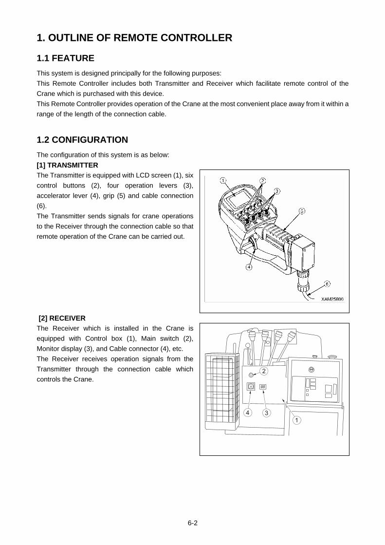
1. OUTLINE OF REMOTE CONTROLLER
1.1 FEATURE
This system is designed principally for the following purposes:
This Remote Controller includes both Transmitter and Receiver which facilitate remote control of the
Crane which is purchased with this device.
This Remote Controller provides operation of the Crane at the most convenient place away from it within a
range of the length of the connection cable.
1.2 CONFIGURATION
The configuration of this system is as below:
[1] TRANSMITTER
The Transmitter is equipped with LCD screen (1), six
control buttons (2), four operation levers (3),
accelerator lever (4), grip (5) and cable connection
(6).
The Transmitter sends signals for crane operations
to the Receiver through the connection cable so that
remote operation of the Crane can be carried out.
[2] RECEIVER
The Receiver which is installed in the Crane is
equipped with Control box (1), Main switch (2),
Monitor display (3), and Cable connector (4), etc.
The Receiver receives operation signals from the
Transmitter through the connection cable which
controls the Crane.
6-2

1.3 FUNCTIONS OF REMOTE CONTROL SYSTEM
• The Transmitter may be operated by one hand, enabling the operator to hold or sling the load with the
other hand at the same time.
• The Accelerator lever controls the Crane operation speed from stand-by, up to maximum speed.
• The LCD screen of the Transmitter indicates operation status, such as “Crane operating”, “Speed
control”, “Outrigger setting” and so on, to provide easy confirmation.
If there is a failure with the Transmitter, the LCD screen will show an error message for easier detection
and correction of the fault.
Furthermore, the voice messages will notify the Transmitter conditions or warning alerts.
• In addition to handling the crane by remote control transmitter, manual operation of the console on the
crane is advised, depending on the type of operation required.
• The connection via the cable between the Transmitter and Receiver allows secure communication
between both.
6-3
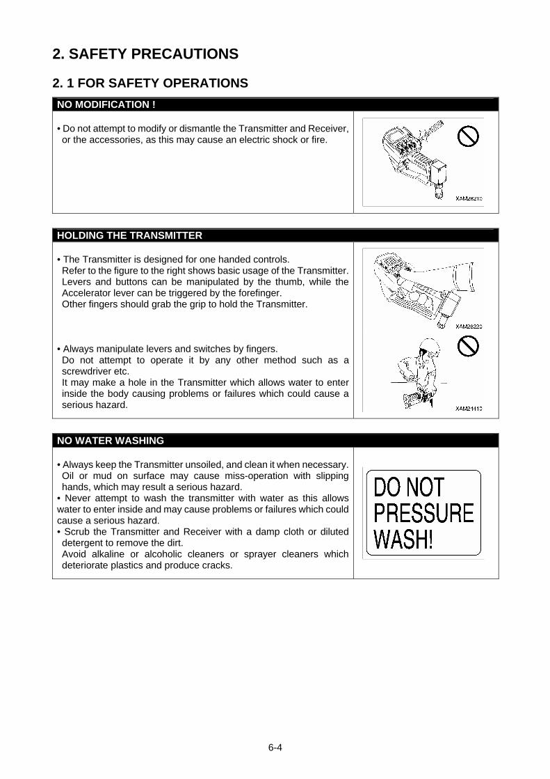
2. SAFETY PRECAUTIONS
2. 1 FOR SAFETY OPERATIONS
NO MODIFICATION ! • Do not attempt to modify or dismantle the Transmitter and Receiver, or the accessories, as this may cause an electric shock or fire.
HOLDING THE TRANSMITTER • The Transmitter is designed for one handed controls. Refer to the figure to the right shows basic usage of the Transmitter. Levers and buttons can be manipulated by the thumb, while the Accelerator lever can be triggered by the forefinger. Other fingers should grab the grip to hold the Transmitter.
• Always manipulate levers and switches by fingers. Do not attempt to operate it by any other method such as a screwdriver etc. It may make a hole in the Transmitter which allows water to enter inside the body causing problems or failures which could cause a serious hazard.
NO WATER WASHING • Always keep the Transmitter unsoiled, and clean it when necessary. Oil or mud on surface may cause miss-operation with slipping hands, which may result a serious hazard.
• Never attempt to wash the transmitter with water as this allows water to enter inside and may cause problems or failures which could cause a serious hazard. • Scrub the Transmitter and Receiver with a damp cloth or diluted detergent to remove the dirt. Avoid alkaline or alcoholic cleaners or sprayer cleaners which deteriorate plastics and produce cracks.
6-4
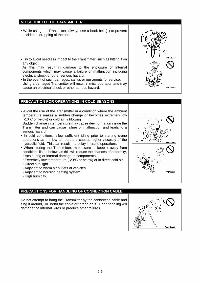
NO SHOCK TO THE TRANSMITTER • While using the Transmitter, always use a hook belt (1) to prevent accidental dropping of the unit.
• Try to avoid needless impact to the Transmitter, such as hitting it on any object. As this may result in damage to the enclosure or internal components which may cause a failure or malfunction including electrical shock or other serious hazard.
• In the event of such damages, call us or our agents for service. Using a damaged Transmitter will result in miss-operation and may cause an electrical shock or other serious hazard.
PRECAUTION FOR OPERATIONS IN COLD SEASONS
• Avoid the use of the Transmitter in a condition where the ambient temperature makes a sudden change or becomes extremely low (-10°C or below) or cold air is blowing Sudden change in temperature may cause dew formation inside the Transmitter and can cause failure or malfunction and leads to a serious hazard.
• In cold conditions, allow sufficient idling prior to starting crane operations as the low temperature causes higher viscosity of the hydraulic fluid. This can result in a delay in crane operations.
• When storing the Transmitter, make sure to keep it away from conditions listed below, as this will reduce the chances of deformity, discolouring or internal damage to components: • Extremely low temperature (-20°C or below) or in direct cold air. • Direct sun light. • Adjacent to warm air outlets of vehicles. • Adjacent to housing heating system. • High humidity.
PRECAUTIONS FOR HANDLING OF CONNECTION CABLE Do not attempt to hang the Transmitter by the connection cable and fling it around, or bend the cable or thread on it. Poor handling will damage the internal wires or produce other failures.
6-5
2.2 PRECAUTIONS FOR CRANE OPERATION
As to matters to be taken care of during operation, refer to the section of “SAFETY”, in addition to the following clauses.
2.2.1 PRIOR TO STARTING ENGINE INSPECTION PRIOR TO STARTING ENGINE
Prior to starting the machine, perform the opening inspection as specified for this machine. Failure to inspect the machine may result in serious injury or death. Any failure detected in the inspection must be properly corrected.
SAFETY MEASURES FOR STARTING ENGINE • Ensure that no unauthorized personnel or obstacles are in the vicinity of the Crane prior to starting the
engine. • Sound the horn before turning the ignition key. • Never attempt to short circuit the starter for the purpose of starting the engine as this may cause fire.
INSPECTION PRIOR TO TURN ON THE TRANSMITTER • Check for any dirt, damage or cracks in the enclosure, control levers, operation buttons, or LCD screen.
• Ensure that the Transmitter’s control levers, operation buttons and the Accelerator lever move smoothly and properly.
• Check the connection cable for damage or crack when the Remote Control Transmitter is in use.
INSPECTION AFTER TURNING ON THE TRANSMITTER
Ensure that LCD screen of the Transmitter provides correct indications. • Switch to each operation mode, i.e. CRANE MODE and OUTRIGGER MODE, then check that LCD screen displays proper indications when each lever and button is manipulated. Furthermore, verify that each applicable value of load in the Transmitter is identical to that of the Moment limiter display.
INSPECTION PRIOR TO TURNING ON THE RECEIVER
• Check for any dirt, damage or cracks in the Receiver’s Control box, Main switch and Monitor display etc.
• Ensure that the Receiver’s Main switch moves smoothly and properly.
6-6

2.2.2 SUBSEQUENT TO STARTING ENGINE
FUNCTION CHECK OF OUTRIGGER MODE BY THE TRANSMITTER, AND NOTICES FOR OPERATION
• Switch the operation mode to the “OUTRIGGER MODE” and confirm that the mode is switched correctly.
• Activate “Start/Reset” button to assure that the engine starts correctly. • Activate “Stop/EMO” button to assure the engine stops correctly. • Operate the outrigger control switches to assure that the corresponding outrigger works correctly. • Check that the position pins for outriggers and retainers are securely fixed.
FUNCTION CHECK OF CRANE MODE BY THE TRANSMITTER AND NOTICES FOR OPERATION
• Before switching the operation mode to “CRANE MODE” make sure all the outriggers are extended and securely placed on the ground.
• Switch the operation mode to the “CRANE MODE” and confirm that the mode is switched correctly. • Activate levers for crane operations and assure that the Crane functions correctly. • Always refer to the portable rated total load chart and avoid over-loaded operations. • Activate the control levers and Accelerator lever of the Transmitter slowly at all times.
2.2.3 TERMINATING THE OPERATION PRECAUTIONS FOR TERMINATING THE OPERATION BY THE TRANSMITTER
• Before stowing the boom, switch the operation mode to “CRANE MODE” and confirm that the mode is switched correctly.
• Before stowing the outriggers, ensure that the boom and the hook is stowed in the correct positions. • Before stowing the outriggers, switch the operation mode to “OUTRIGGER MODE” and confirm that the mode is switched correctly.
• When all the operation of the Transmitter is complete, always turn OFF the power of both the Transmitter and Receiver.
• Under no condition will the Transmitter be ON unless the Crane is in operation, otherwise, unexpected touching or contact of operation levers or buttons of the Transmitter by any other object, may cause un-desired motion of the Crane and a serious accident such as tipping or collision may occur.
• Inspection may require the Transmitter to be turned ON, but as a precaution make sure to stop the engine and turn the Receiver OFF.
6-7
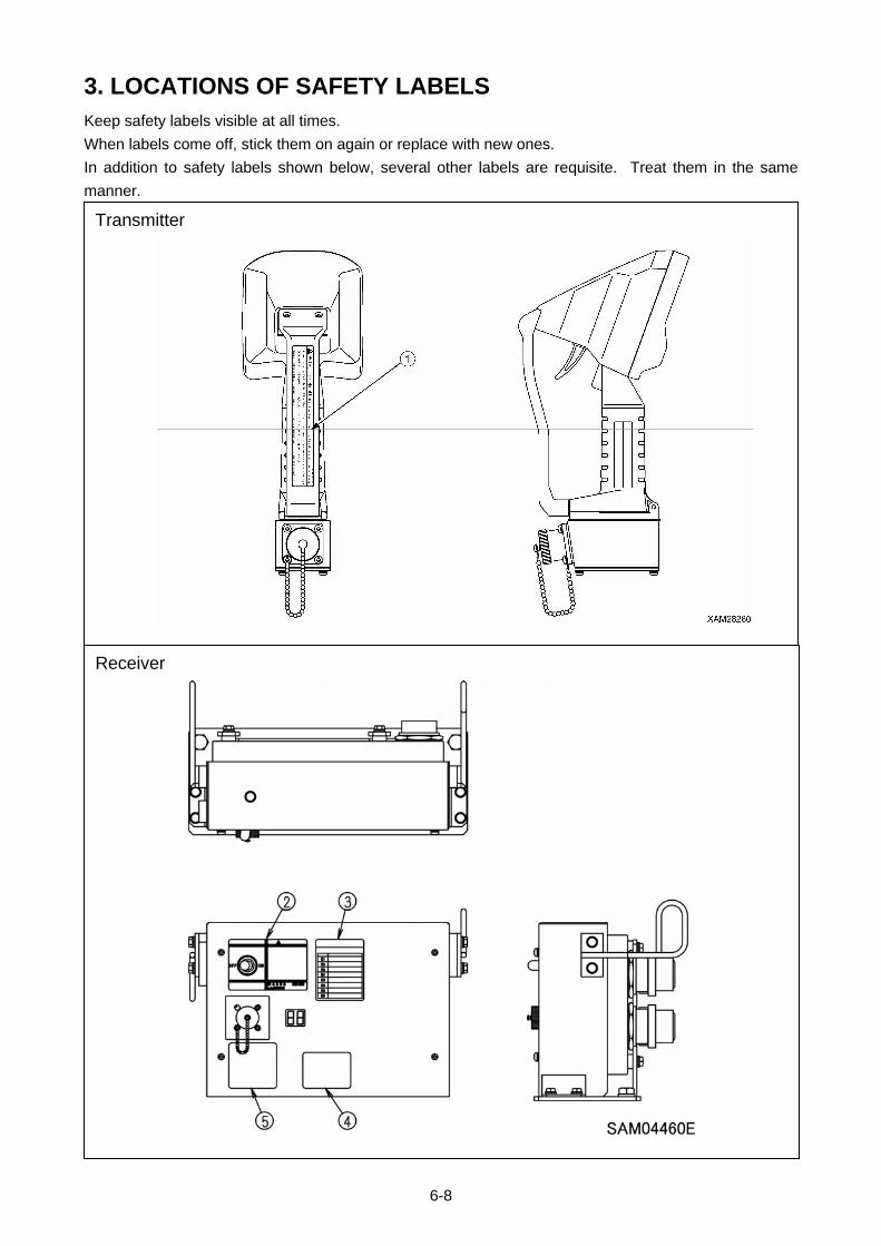
3. LOCATIONS OF SAFETY LABELS Keep safety labels visible at all times.
When labels come off, stick them on again or replace with new ones.
In addition to safety labels shown below, several other labels are requisite. Treat them in the same
manner.
Receiver
Transmitter
6-8
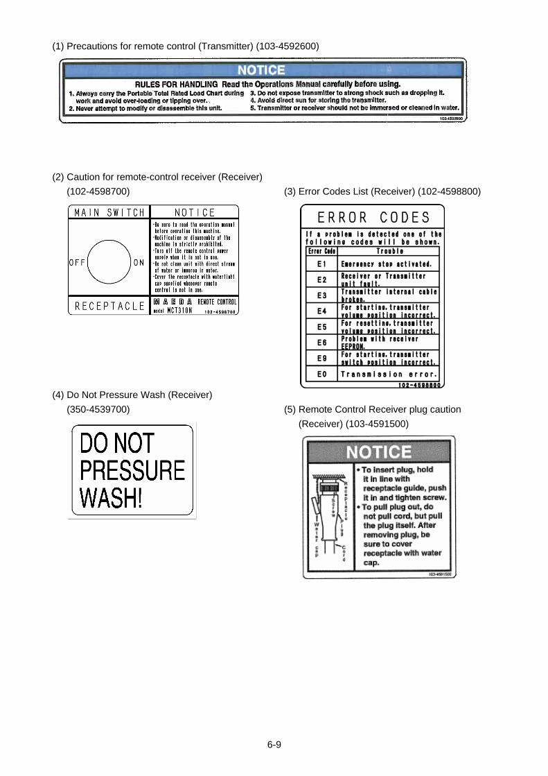
(1) Precautions for remote control (Transmitter) (103-4592600)
(2) Caution for remote-control receiver (Receiver)
(102-4598700)
(3) Error Codes List (Receiver) (102-4598800)
(4) Do Not Pressure Wash (Receiver)
(350-4539700)
(5) Remote Control Receiver plug caution
(Receiver) (103-4591500)
6-9
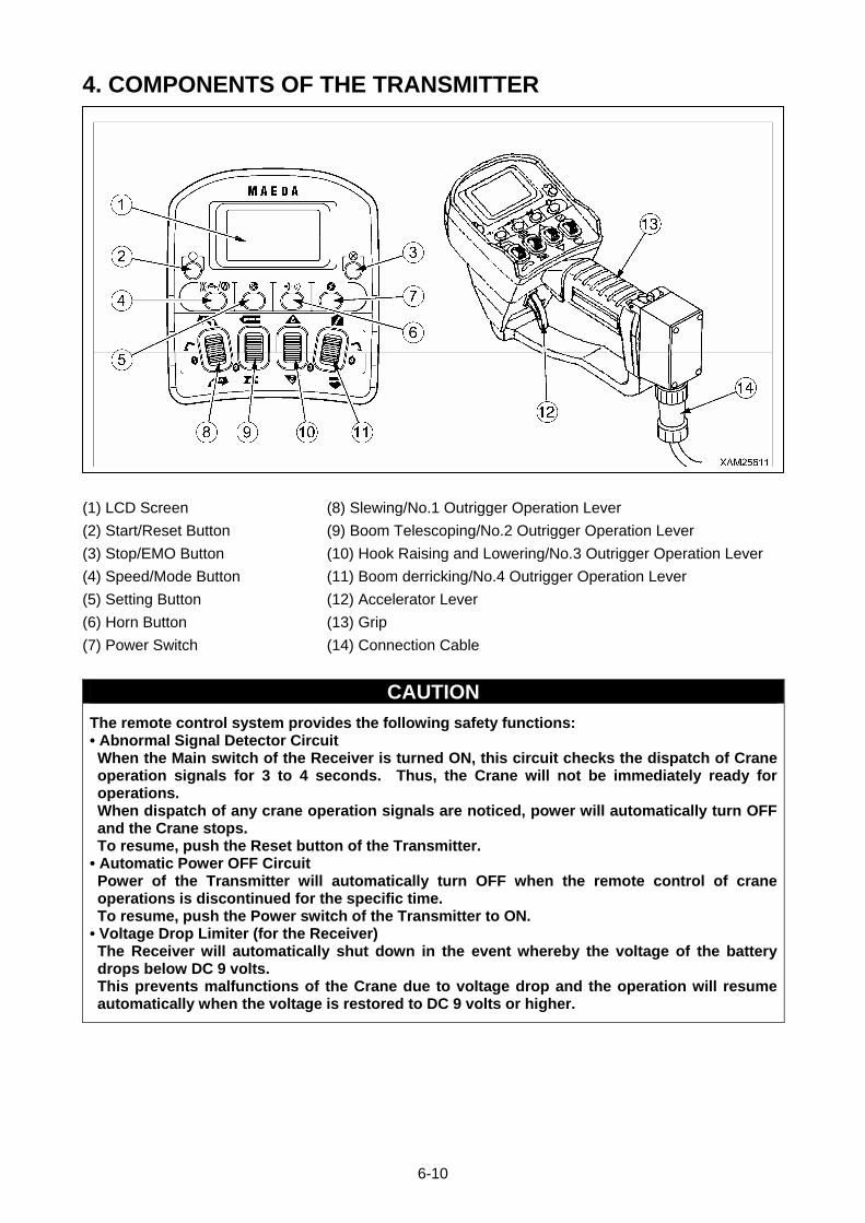
4. COMPONENTS OF THE TRANSMITTER
(1) LCD Screen (8) Slewing/No.1 Outrigger Operation Lever
(2) Start/Reset Button (9) Boom Telescoping/No.2 Outrigger Operation Lever
(3) Stop/EMO Button (10) Hook Raising and Lowering/No.3 Outrigger Operation Lever
(4) Speed/Mode Button (11) Boom derricking/No.4 Outrigger Operation Lever
(5) Setting Button (12) Accelerator Lever
(6) Horn Button (13) Grip
(7) Power Switch (14) Connection Cable
CAUTION
The remote control system provides the following safety functions: • Abnormal Signal Detector Circuit When the Main switch of the Receiver is turned ON, this circuit checks the dispatch of Crane operation signals for 3 to 4 seconds. Thus, the Crane will not be immediately ready for operations. When dispatch of any crane operation signals are noticed, power will automatically turn OFF and the Crane stops. To resume, push the Reset button of the Transmitter.
• Automatic Power OFF Circuit Power of the Transmitter will automatically turn OFF when the remote control of crane operations is discontinued for the specific time. To resume, push the Power switch of the Transmitter to ON.
• Voltage Drop Limiter (for the Receiver) The Receiver will automatically shut down in the event whereby the voltage of the battery drops below DC 9 volts. This prevents malfunctions of the Crane due to voltage drop and the operation will resume automatically when the voltage is restored to DC 9 volts or higher.
6-10
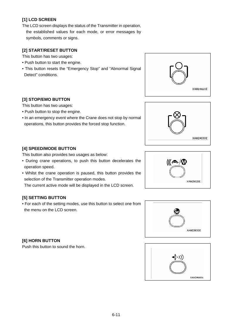
[1] LCD SCREEN
The LCD screen displays the status of the Transmitter in operation,
the established values for each mode, or error messages by
symbols, comments or signs.
[2] START/RESET BUTTON
This button has two usages:
• Push button to start the engine.
• This button resets the “Emergency Stop” and “Abnormal Signal
Detect” conditions.
[3] STOP/EMO BUTTON
This button has two usages:
• Push button to stop the engine.
• In an emergency event where the Crane does not stop by normal
operations, this button provides the forced stop function.
[4] SPEED/MODE BUTTON
This button also provides two usages as below:
• During crane operations, to push this button decelerates the
operation speed.
• Whilst the crane operation is paused, this button provides the
selection of the Transmitter operation modes.
The current active mode will be displayed in the LCD screen.
[5] SETTING BUTTON
• For each of the setting modes, use this button to select one from
the menu on the LCD screen.
[6] HORN BUTTON
Push this button to sound the horn.
6-11
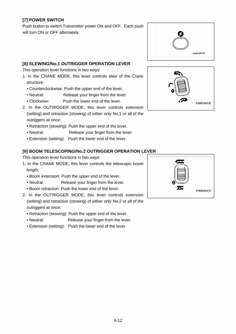
[7] POWER SWITCH
Push button to switch Transmitter power ON and OFF. Each push
will turn ON or OFF alternately.
[8] SLEWING/No.1 OUTRIGGER OPERATION LEVER
This operation lever functions in two ways:
1. In the CRANE MODE, this lever controls slew of the Crane
structure:
• Counterclockwise: Push the upper end of the lever.
• Neutral: Release your finger from the lever.
• Clockwise: Push the lower end of the lever.
2. In the OUTRIGGER MODE, this lever controls extension
(setting) and retraction (stowing) of either only No.1 or all of the
outriggers at once:
• Retraction (stowing): Push the upper end of the lever.
• Neutral: Release your finger from the lever.
• Extension (setting): Push the lower end of the lever.
[9] BOOM TELESCOPING/No.2 OUTRIGGER OPERATION LEVER
This operation lever functions in two ways:
1. In the CRANE MODE, this lever controls the telescopic boom
length:
• Boom extension: Push the upper end of the lever.
• Neutral: Release your finger from the lever.
• Boom retraction: Push the lower end of the lever.
2. In the OUTRIGGER MODE, this lever controls extension
(setting) and retraction (stowing) of either only No.2 or all of the
outriggers at once:
• Retraction (stowing): Push the upper end of the lever.
• Neutral: Release your finger from the lever.
• Extension (setting): Push the lower end of the lever.
6-12
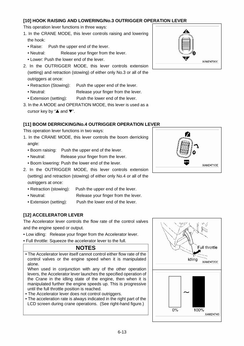
[10] HOOK RAISING AND LOWERING/No.3 OUTRIGGER OPERATION LEVER
This operation lever functions in three ways:
1. In the CRANE MODE, this lever controls raising and lowering
the hook:
• Raise: Push the upper end of the lever.
• Neutral: Release your finger from the lever.
• Lower: Push the lower end of the lever.
2. In the OUTRIGGER MODE, this lever controls extension
(setting) and retraction (stowing) of either only No.3 or all of the
outriggers at once:
• Retraction (Stowing): Push the upper end of the lever.
• Neutral: Release your finger from the lever.
• Extension (setting): Push the lower end of the lever.
3. In the A MODE and OPERATION MODE, this lever is used as a
cursor key by “ and ”.
[11] BOOM DERRICKING/No.4 OUTRIGGER OPERATION LEVER
This operation lever functions in two ways:
1. In the CRANE MODE, this lever controls the boom derricking
angle:
• Boom raising: Push the upper end of the lever.
• Neutral: Release your finger from the lever.
• Boom lowering: Push the lower end of the lever.
2. In the OUTRIGGER MODE, this lever controls extension
(setting) and retraction (stowing) of either only No.4 or all of the
outriggers at once:
• Retraction (stowing): Push the upper end of the lever.
• Neutral: Release your finger from the lever.
• Extension (setting): Push the lower end of the lever.
[12] ACCELERATOR LEVER
The Accelerator lever controls the flow rate of the control valves
and the engine speed or output.
• Low idling: Release your finger from the Accelerator lever.
• Full throttle: Squeeze the accelerator lever to the full.
NOTES • The Accelerator lever itself cannot control either flow rate of the control valves or the engine speed when it is manipulated alone. When used in conjunction with any of the other operation levers, the Accelerator lever launches the specified operation of the Crane in the idling state of the engine, then when it is manipulated further the engine speeds up. This is progressive until the full throttle position is reached.
• The Accelerator lever does not control outriggers. • The acceleration rate is always indicated in the right part of the LCD screen during crane operations. (See right-hand figure.)
6-13
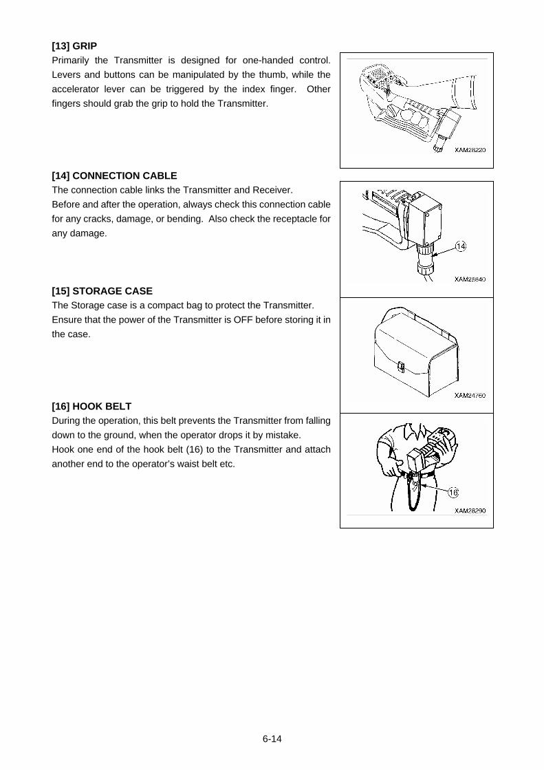
[13] GRIP
Primarily the Transmitter is designed for one-handed control.
Levers and buttons can be manipulated by the thumb, while the
accelerator lever can be triggered by the index finger. Other
fingers should grab the grip to hold the Transmitter.
[14] CONNECTION CABLE
The connection cable links the Transmitter and Receiver.
Before and after the operation, always check this connection cable
for any cracks, damage, or bending. Also check the receptacle for
any damage.
[15] STORAGE CASE
The Storage case is a compact bag to protect the Transmitter.
Ensure that the power of the Transmitter is OFF before storing it in
the case.
[16] HOOK BELT
During the operation, this belt prevents the Transmitter from falling
down to the ground, when the operator drops it by mistake.
Hook one end of the hook belt (16) to the Transmitter and attach
another end to the operator’s waist belt etc.
6-14
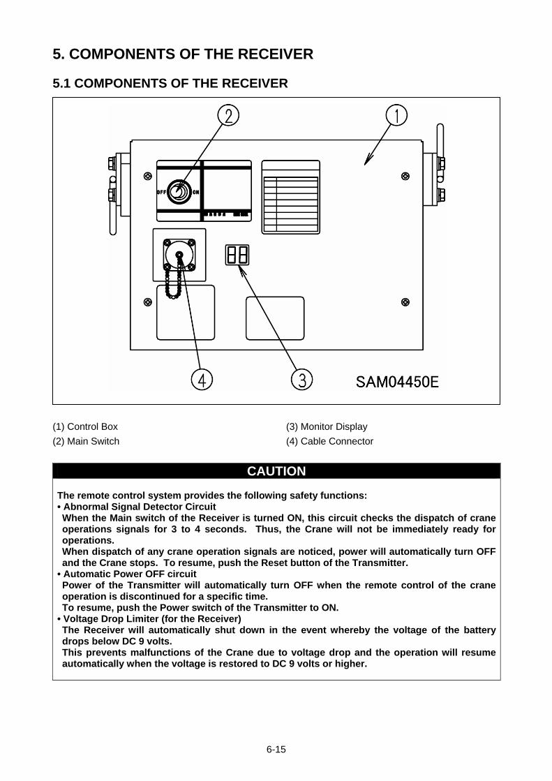
5. COMPONENTS OF THE RECEIVER
5.1 COMPONENTS OF THE RECEIVER
(1) Control Box (3) Monitor Display
(2) Main Switch (4) Cable Connector
CAUTION
The remote control system provides the following safety functions: • Abnormal Signal Detector Circuit When the Main switch of the Receiver is turned ON, this circuit checks the dispatch of crane operations signals for 3 to 4 seconds. Thus, the Crane will not be immediately ready for operations. When dispatch of any crane operation signals are noticed, power will automatically turn OFF and the Crane stops. To resume, push the Reset button of the Transmitter.
• Automatic Power OFF circuit Power of the Transmitter will automatically turn OFF when the remote control of the crane operation is discontinued for a specific time. To resume, push the Power switch of the Transmitter to ON.
• Voltage Drop Limiter (for the Receiver) The Receiver will automatically shut down in the event whereby the voltage of the battery drops below DC 9 volts. This prevents malfunctions of the Crane due to voltage drop and the operation will resume automatically when the voltage is restored to DC 9 volts or higher.
6-15
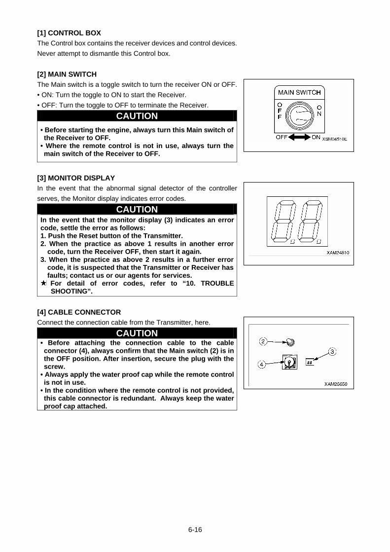
[1] CONTROL BOX
The Control box contains the receiver devices and control devices.
Never attempt to dismantle this Control box.
[2] MAIN SWITCH
The Main switch is a toggle switch to turn the receiver ON or OFF.
• ON: Turn the toggle to ON to start the Receiver.
• OFF: Turn the toggle to OFF to terminate the Receiver.
CAUTION
• Before starting the engine, always turn this Main switch of the Receiver to OFF.
• Where the remote control is not in use, always turn the main switch of the Receiver to OFF.
[3] MONITOR DISPLAY
In the event that the abnormal signal detector of the controller
serves, the Monitor display indicates error codes.
CAUTION In the event that the monitor display (3) indicates an error code, settle the error as follows: 1. Push the Reset button of the Transmitter. 2. When the practice as above 1 results in another error
code, turn the Receiver OFF, then start it again. 3. When the practice as above 2 results in a further error
code, it is suspected that the Transmitter or Receiver has faults; contact us or our agents for services. For detail of error codes, refer to “10. TROUBLE SHOOTING”.
[4] CABLE CONNECTOR
Connect the connection cable from the Transmitter, here.
CAUTION • Before attaching the connection cable to the cable connector (4), always confirm that the Main switch (2) is in the OFF position. After insertion, secure the plug with the screw.
• Always apply the water proof cap while the remote control is not in use.
• In the condition where the remote control is not provided, this cable connector is redundant. Always keep the water proof cap attached.
6-16
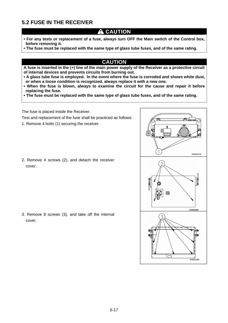
5.2 FUSE IN THE RECEIVER
• For any tests or replacement of a fuse, always turn OFF the Main switch of the Control box, before removing it.
• The fuse must be replaced with the same type of glass tube fuses, and of the same rating.
CAUTION A fuse is inserted in the (+) line of the main power supply of the Receiver as a protective circuit of internal devices and prevents circuits from burning out. • A glass tube fuse is employed. In the event where the fuse is corroded and shows white dust, or when a loose condition is recognized, always replace it with a new one.
• When the fuse is blown, always to examine the circuit for the cause and repair it before replacing the fuse.
• The fuse must be replaced with the same type of glass tube fuses, and of the same rating.
The fuse is placed inside the Receiver.
Test and replacement of the fuse shall be practiced as follows:
1. Remove 4 bolts (1) securing the receiver.
2. Remove 4 screws (2), and detach the receiver
cover.
3. Remove 8 screws (3), and take off the internal
cover.
6-17
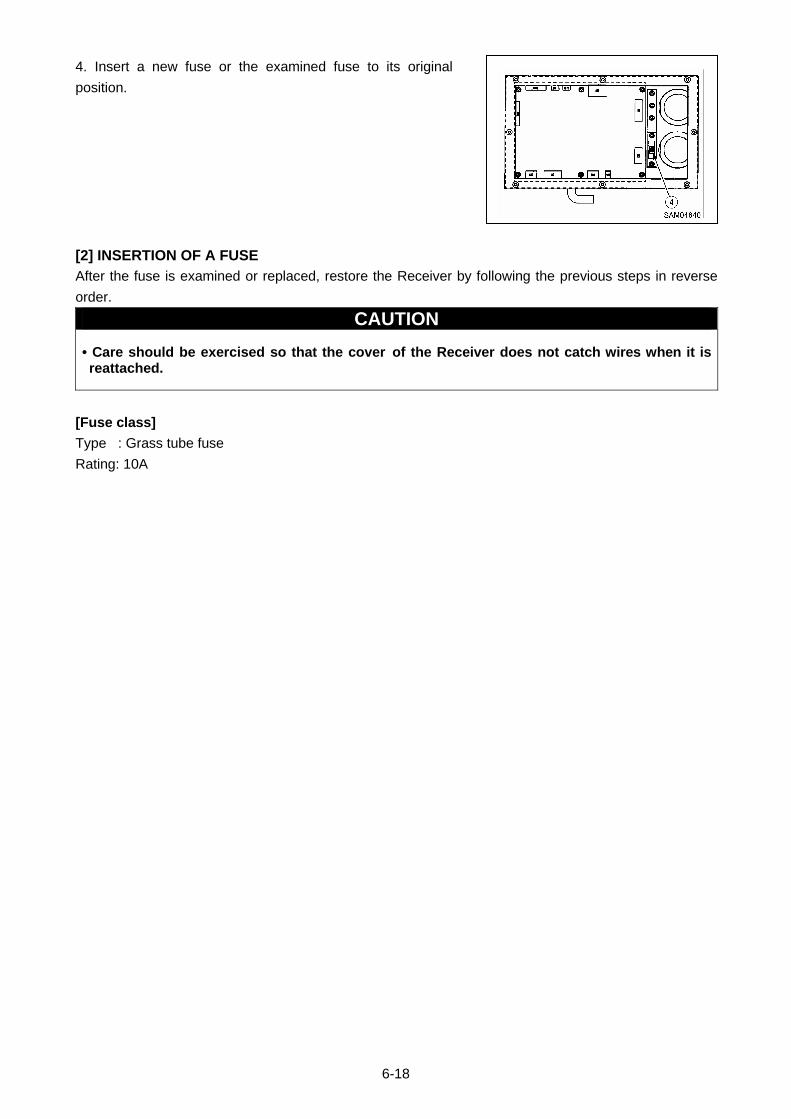
4. Insert a new fuse or the examined fuse to its original
position.
[2] INSERTION OF A FUSE
After the fuse is examined or replaced, restore the Receiver by following the previous steps in reverse
order.
CAUTION
• Care should be exercised so that the cover of the Receiver does not catch wires when it is reattached.
[Fuse class]
Type : Grass tube fuse
Rating: 10A
6-18
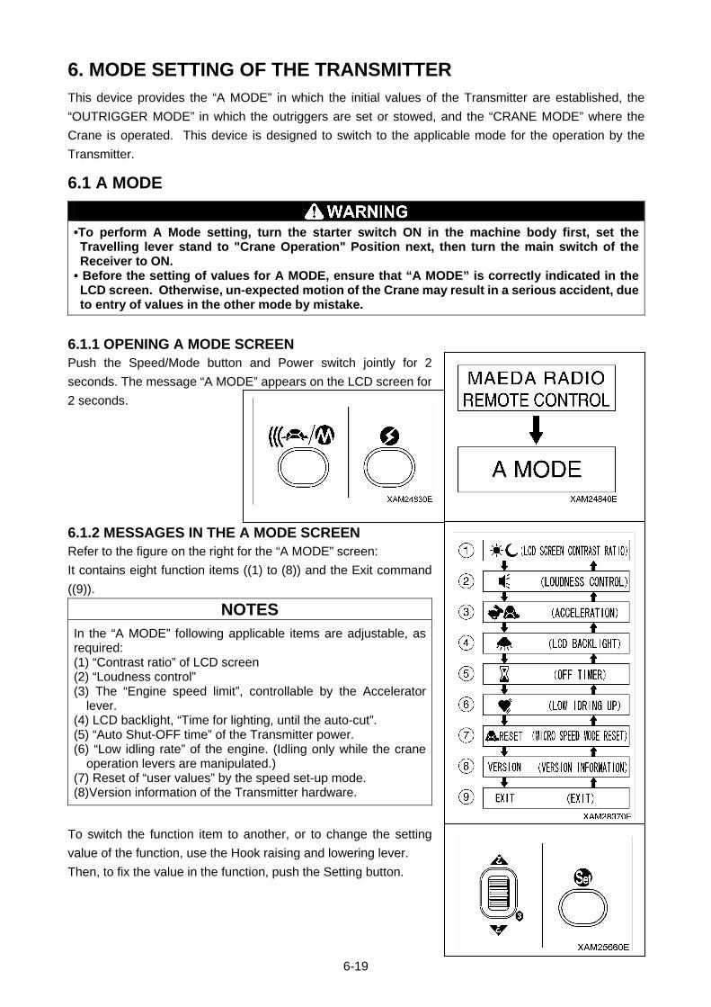
6. MODE SETTING OF THE TRANSMITTER This device provides the “A MODE” in which the initial values of the Transmitter are established, the
“OUTRIGGER MODE” in which the outriggers are set or stowed, and the “CRANE MODE” where the
Crane is operated. This device is designed to switch to the applicable mode for the operation by the
Transmitter.
6.1 A MODE
•To perform A Mode setting, turn the starter switch ON in the machine body first, set the Travelling lever stand to "Crane Operation" Position next, then turn the main switch of the Receiver to ON.
• Before the setting of values for A MODE, ensure that “A MODE” is correctly indicated in the LCD screen. Otherwise, un-expected motion of the Crane may result in a serious accident, due to entry of values in the other mode by mistake.
6.1.1 OPENING A MODE SCREEN Push the Speed/Mode button and Power switch jointly for 2
seconds. The message “A MODE” appears on the LCD screen for
2 seconds.
6.1.2 MESSAGES IN THE A MODE SCREEN
Refer to the figure on the right for the “A MODE” screen:
It contains eight function items ((1) to (8)) and the Exit command
((9)).
NOTES
In the “A MODE” following applicable items are adjustable, as required: (1) “Contrast ratio” of LCD screen (2) “Loudness control” (3) The “Engine speed limit”, controllable by the Accelerator
lever. (4) LCD backlight, “Time for lighting, until the auto-cut”. (5) “Auto Shut-OFF time” of the Transmitter power. (6) “Low idling rate” of the engine. (Idling only while the crane
operation levers are manipulated.) (7) Reset of “user values” by the speed set-up mode. (8)Version information of the Transmitter hardware.
To switch the function item to another, or to change the setting
value of the function, use the Hook raising and lowering lever.
Then, to fix the value in the function, push the Setting button.
6-19
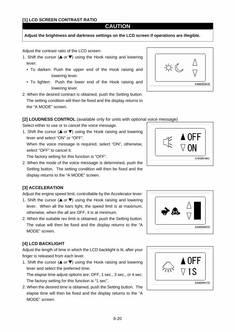
[1] LCD SCREEN CONTRAST RATIO
CAUTION
Adjust the brightness and darkness settings on the LCD screen if operations are illegible.
Adjust the contrast ratio of the LCD screen:
1. Shift the cursor ( or ) using the Hook raising and lowering
lever.
• To darken: Push the upper end of the Hook raising and
lowering lever.
• To lighten: Push the lower end of the Hook raising and
lowering lever.
2. When the desired contract is obtained, push the Setting button.
The setting condition will then be fixed and the display returns to
the “A MODE” screen.
[2] LOUDNESS CONTROL (available only for units with optional voice message)
Select either to use or to cancel the voice message.
1. Shift the cursor ( or ) using the Hook raising and lowering
lever and select “ON” or “OFF”.
When the voice message is required, select "ON", otherwise,
select "OFF" to cancel it.
The factory setting for this function is “OFF”.
2. When the mode of the voice message is determined, push the
Setting button. The setting condition will then be fixed and the
display returns to the “A MODE” screen.
[3] ACCELERATION
Adjust the engine speed limit, controllable by the Accelerator lever:
1. Shift the cursor ( or ) using the Hook raising and lowering
lever. When all the bars light, the speed limit is at maximum,
otherwise, when the all are OFF, it is at minimum.
2. When the suitable rev limit is obtained, push the Setting button.
The value will then be fixed and the display returns to the “A
MODE” screen.
[4] LCD BACKLIGHT
Adjust the length of time in which the LCD backlight is lit, after your
finger is released from each lever.
1. Shift the cursor ( or ) using the Hook raising and lowering
lever and select the preferred time.
The elapse time adjust options are: OFF, 1 sec., 3 sec., or 4 sec.
The factory setting for this function is “1 sec”.
2. When the desired time is obtained, push the Setting button. The
elapse time will then be fixed and the display returns to the “A
MODE” screen.
6-20
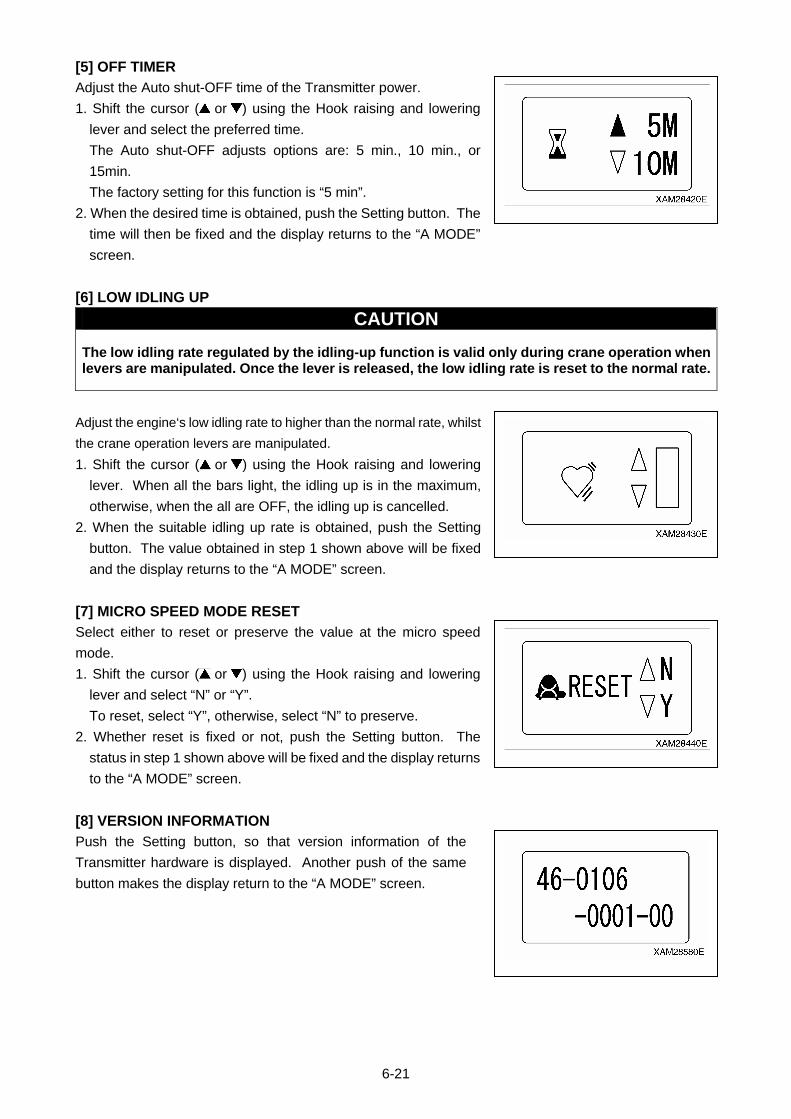
[5] OFF TIMER
Adjust the Auto shut-OFF time of the Transmitter power.
1. Shift the cursor ( or ) using the Hook raising and lowering
lever and select the preferred time.
The Auto shut-OFF adjusts options are: 5 min., 10 min., or
15min.
The factory setting for this function is “5 min”.
2. When the desired time is obtained, push the Setting button. The
time will then be fixed and the display returns to the “A MODE”
screen.
[6] LOW IDLING UP
CAUTION
The low idling rate regulated by the idling-up function is valid only during crane operation when levers are manipulated. Once the lever is released, the low idling rate is reset to the normal rate.
Adjust the engine‘s low idling rate to higher than the normal rate, whilst
the crane operation levers are manipulated.
1. Shift the cursor ( or ) using the Hook raising and lowering
lever. When all the bars light, the idling up is in the maximum,
otherwise, when the all are OFF, the idling up is cancelled.
2. When the suitable idling up rate is obtained, push the Setting
button. The value obtained in step 1 shown above will be fixed
and the display returns to the “A MODE” screen.
[7] MICRO SPEED MODE RESET
Select either to reset or preserve the value at the micro speed
mode.
1. Shift the cursor ( or ) using the Hook raising and lowering
lever and select “N” or “Y”.
To reset, select “Y”, otherwise, select “N” to preserve.
2. Whether reset is fixed or not, push the Setting button. The
status in step 1 shown above will be fixed and the display returns
to the “A MODE” screen.
[8] VERSION INFORMATION
Push the Setting button, so that version information of the
Transmitter hardware is displayed. Another push of the same
button makes the display return to the “A MODE” screen.
6-21

[9] EXIT
CAUTION Once setting-up the desired function items are completed, do not forget to practice the termination procedure, outlined below. Otherwise, when this process is not correctly terminated, the latest setting will not become valid.
1. Once setting-up the desired function items are completed,
ensure that the display has returned to the “A MODE” screen.
2. Shift the cursor ( or ) using the Hook raising and lowering
lever and select “EXIT”.
3. Push the Setting button, which will terminate the “A MODE” and
turn the mode to the “CRANE MODE”.
6-22
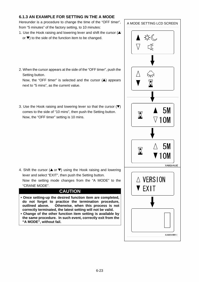
6.1.3 AN EXAMPLE FOR SETTING IN THE A MODE
A MODE SETTING LCD SCREENHereunder is a procedure to change the time of the “OFF timer”,
from “5 minutes” of the factory setting, to 10 minutes:
1. Use the Hook raising and lowering lever and shift the cursor (
or ) to the side of the function item to be changed.
2. When the cursor appears at the side of the “OFF timer”, push the
Setting button.
Now, the “OFF timer” is selected and the cursor ( ) appears
next to ”5 mins”, as the current value.
3. Use the Hook raising and lowering lever so that the cursor ( )
comes to the side of “10 mins”, then push the Setting button.
Now, the “OFF timer” setting is 10 mins.
4. Shift the cursor ( or ) using the Hook raising and lowering
lever and select “EXIT”, then push the Setting button.
Now the setting mode changes from the “A MODE” to the
“CRANE MODE”.
CAUTION • Once setting-up the desired function item are completed, do not forget to practice the termination procedure, outlined above. Otherwise, when this process is not correctly terminated, the latest setting will not be valid.
• Change of the other function item setting is available by the same procedure. In such event, correctly exit from the “A MODE”, without fail.
6-23

6.2 PROCEDURE IN THE OPERATION MODE
CAUTION
When the Main switch of the Receiver is turned ON, its abnormal signal detector automatically starts. Do not use levers, buttons or the Accelerator lever for 3 – 4 seconds.
NOTES
• For changes between the modes, always turn OFF the power, once, then push the Power button again to power ON.
• While using a mode other than the “CRANE MODE”, when you turn OFF the power by the Power switch and turn it ON, again (i.e., you keep waiting for 2 seconds or more), the mode is automatically set to “CRANE MODE”. When you want to continue the operation in the previous mode, call the appropriate mode, again.
6.2.1 CALL OUT CRANE MODE
1. Push the Power button to turn ON the Transmitter.
The “Crane mark” is displayed in the LCD screen for about 2
seconds.
NOTES
In case the power is already ON, turn OFF once, and then push the Power button ON again.
2. When the “Crane mark” in the LCD screen disappears in 2
seconds, the “CRANE MODE” is automatically called out.
6-24
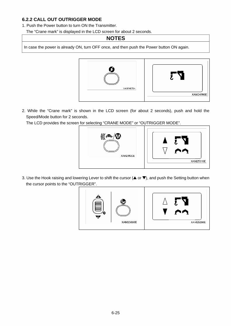
6.2.2 CALL OUT OUTRIGGER MODE
1. Push the Power button to turn ON the Transmitter.
The “Crane mark” is displayed in the LCD screen for about 2 seconds.
NOTES
In case the power is already ON, turn OFF once, and then push the Power button ON again.
2. While the “Crane mark” is shown in the LCD screen (for about 2 seconds), push and hold the
Speed/Mode button for 2 seconds.
The LCD provides the screen for selecting “CRANE MODE” or “OUTRIGGER MODE”.
3. Use the Hook raising and lowering Lever to shift the cursor ( or ), and push the Setting button when
the cursor points to the “OUTRIGGER”.
6-25

4. The operation mode is already switched to the “OUTRIGGER MODE”, thus the “Outrigger mark” is
exhibited.
Soon after, it enters into “Outrigger setting mode”, then the mark turns to “Outrigger setting mode “.
6-26
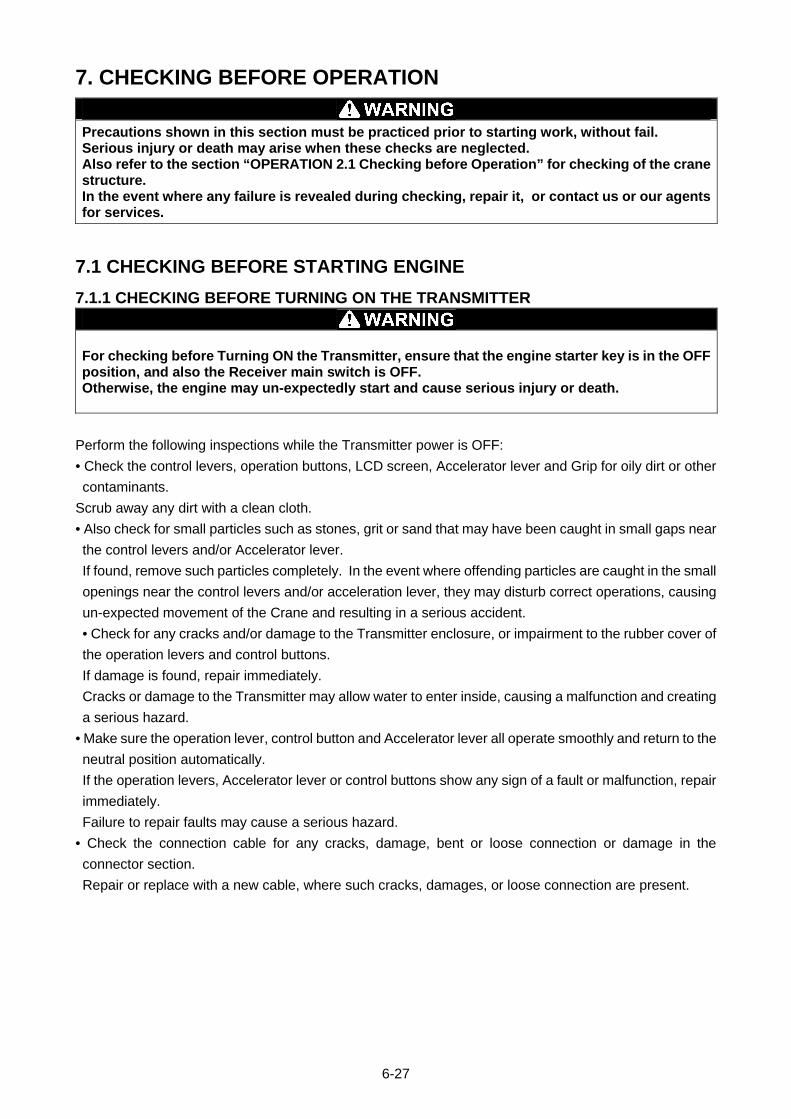
7. CHECKING BEFORE OPERATION
Precautions shown in this section must be practiced prior to starting work, without fail. Serious injury or death may arise when these checks are neglected. Also refer to the section “OPERATION 2.1 Checking before Operation” for checking of the crane structure. In the event where any failure is revealed during checking, repair it, or contact us or our agents for services.
7.1 CHECKING BEFORE STARTING ENGINE
7.1.1 CHECKING BEFORE TURNING ON THE TRANSMITTER
For checking before Turning ON the Transmitter, ensure that the engine starter key is in the OFF position, and also the Receiver main switch is OFF. Otherwise, the engine may un-expectedly start and cause serious injury or death.
Perform the following inspections while the Transmitter power is OFF:
• Check the control levers, operation buttons, LCD screen, Accelerator lever and Grip for oily dirt or other
contaminants.
Scrub away any dirt with a clean cloth.
• Also check for small particles such as stones, grit or sand that may have been caught in small gaps near
the control levers and/or Accelerator lever.
If found, remove such particles completely. In the event where offending particles are caught in the small
openings near the control levers and/or acceleration lever, they may disturb correct operations, causing
un-expected movement of the Crane and resulting in a serious accident.
• Check for any cracks and/or damage to the Transmitter enclosure, or impairment to the rubber cover of
the operation levers and control buttons.
If damage is found, repair immediately.
Cracks or damage to the Transmitter may allow water to enter inside, causing a malfunction and creating
a serious hazard.
• Make sure the operation lever, control button and Accelerator lever all operate smoothly and return to the
neutral position automatically.
If the operation levers, Accelerator lever or control buttons show any sign of a fault or malfunction, repair
immediately.
Failure to repair faults may cause a serious hazard.
• Check the connection cable for any cracks, damage, bent or loose connection or damage in the
connector section.
Repair or replace with a new cable, where such cracks, damages, or loose connection are present.
6-27
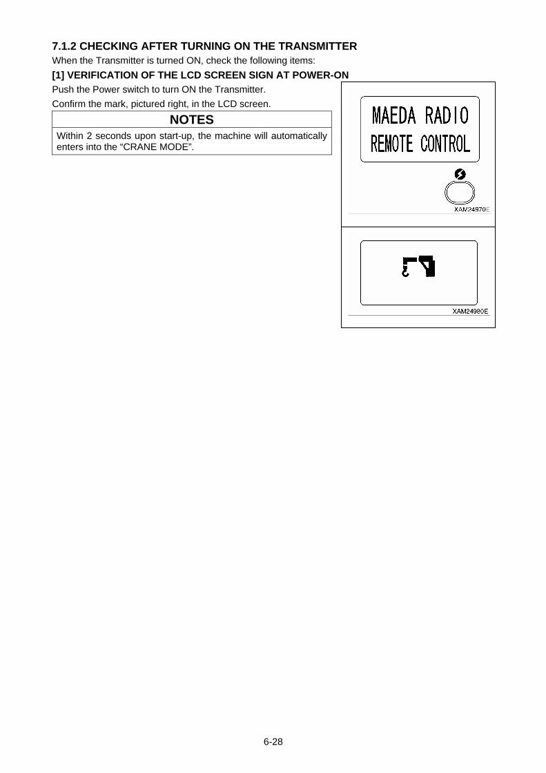
7.1.2 CHECKING AFTER TURNING ON THE TRANSMITTER When the Transmitter is turned ON, check the following items:
[1] VERIFICATION OF THE LCD SCREEN SIGN AT POWER-ON
Push the Power switch to turn ON the Transmitter.
Confirm the mark, pictured right, in the LCD screen.
NOTES
Within 2 seconds upon start-up, the machine will automatically enters into the “CRANE MODE”.
6-28

[2] VERIFICATION OF THE LCD SCREEN SIGN AT THE “CRANE MODE”
1. Check Accelerator lever corresponds to LCD screen by pulling
lever to full throttle and checking for all bars to be present.
2. Slowly decrease the pressure on the Accelerator lever and
check the bars also decrease on the LCD screen.
3. Release all pressure on the Accelerator lever to check idling,
where all bars on the LCD screen are absent.
4. Manipulate each operation lever and verify that each indication
on the LCD screen is correct.
5. Manipulate each operation button and verify that each indication
on the LCD screen is correct.
6. Verify that “START” is correctly displayed on the LCD screen
when the Start/Reset button is pushed.
7. Also, verify that “STOP” is correctly displayed on the LCD screen
when the Stop/EMO button is pushed.
6-29
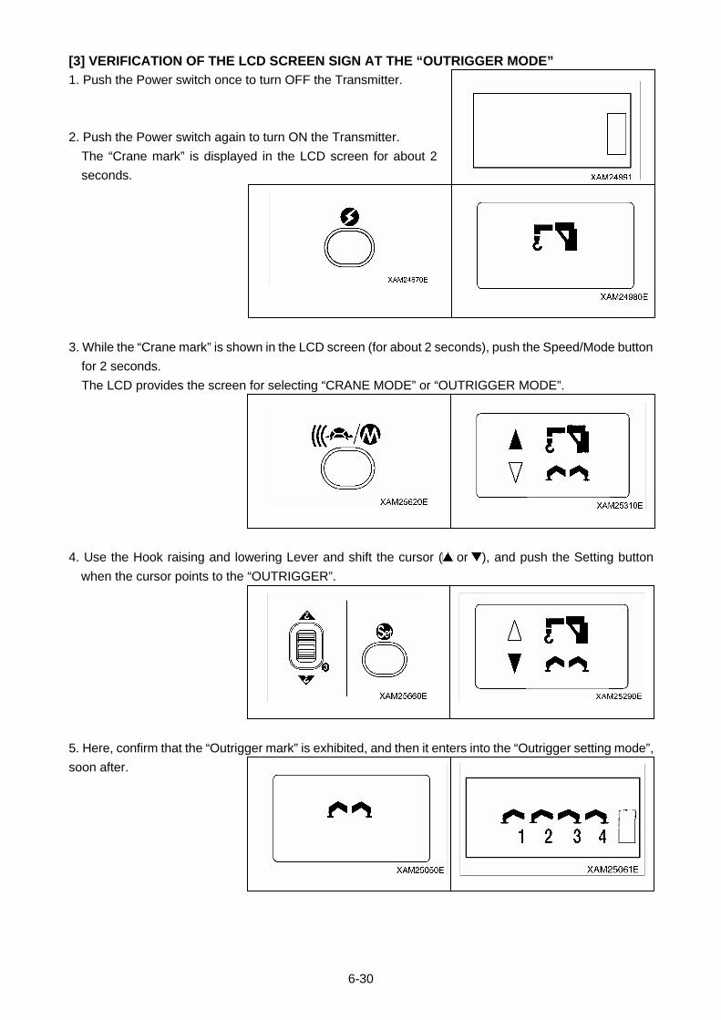
[3] VERIFICATION OF THE LCD SCREEN SIGN AT THE “OUTRIGGER MODE”
1. Push the Power switch once to turn OFF the Transmitter.
2. Push the Power switch again to turn ON the Transmitter.
The “Crane mark” is displayed in the LCD screen for about 2
seconds.
3. While the “Crane mark” is shown in the LCD screen (for about 2 seconds), push the Speed/Mode button
for 2 seconds.
The LCD provides the screen for selecting “CRANE MODE” or “OUTRIGGER MODE”.
4. Use the Hook raising and lowering Lever and shift the cursor ( or ), and push the Setting button
when the cursor points to the “OUTRIGGER”.
5. Here, confirm that the “Outrigger mark” is exhibited, and then it enters into the “Outrigger setting mode”,
soon after.
6-30

6. Manipulate each operation lever and verify that each indication in the LCD screen is correct.
6-31
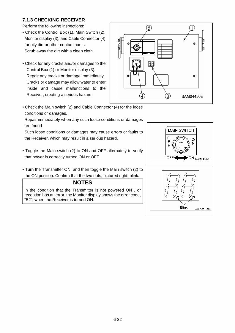
7.1.3 CHECKING RECEIVER Perform the following inspections:
• Check the Control Box (1), Main Switch (2),
Monitor display (3), and Cable Connector (4)
for oily dirt or other contaminants.
Scrub away the dirt with a clean cloth.
• Check for any cracks and/or damages to the
Control Box (1) or Monitor display (3).
Repair any cracks or damage immediately.
Cracks or damage may allow water to enter
inside and cause malfunctions to the
Receiver, creating a serious hazard.
• Check the Main switch (2) and Cable Connector (4) for the loose
conditions or damages.
Repair immediately when any such loose conditions or damages
are found.
Such loose conditions or damages may cause errors or faults to
the Receiver, which may result in a serious hazard.
• Toggle the Main switch (2) to ON and OFF alternately to verify
that power is correctly turned ON or OFF.
• Turn the Transmitter ON, and then toggle the Main switch (2) to
the ON position. Confirm that the two dots, pictured right, blink.
NOTES
In the condition that the Transmitter is not powered ON , or reception has an error, the Monitor display shows the error code, “E2”, when the Receiver is turned ON.
6-32
7.2 CHECKING AFTER STARTING ENGINE
Precautions shown in this section must be practiced prior to starting work, without fail. Serious injury or death may arise when these inspections are neglected. Refer to the section “OPERATION 2.1 Checking before Operation” for checking of the crane structure. Whenever any failures are revealed during such inspections, repair them, or contact us or our agents for services.
7.2.1 VERIFICATION FOR THE ENGINE START AND STOP
• Ensure that the boom and outriggers are all stowed in the correct positions. If they are not in the correct positions, use the applicable levers to stow them correctly. Otherwise, the Transmitter operation may cause damage to the Crane or tipping that results in serious injury or death.
• If the Transmitter LCD screen shows an error message or the Receiver Monitor display shows an error code, the crane will not operate. Examine the cause of the error and perform appropriate service when any fault is identified, or contact us or our agents for services.
[1] CHECKING ENGINE START OPERATION
1. Position the Starter Switch of the Crane to ON.
2. Set the travelling stand of the Crane to CRANE position.
3. Turn ON the main switch of the Receiver.
4. Push the Power switch of the Transmitter, to ON.
5. Then push the Horn button and confirm the horn sound.
6. Use the Start/Reset button to check that the engine starts
properly.
7. Check whether the indication “START” appears on the LCD
screen.
CAUTION
Prior to starting the engine, perform the following: 1. Set the Acceleration Lever to the medium speed (nealy
middle in its stroke). 2. Pull out the choke knob. 3. Return the choke knob to its initial position, when the
engine starts.
[2] CHECKING ENGINE EMERGENCY STOP OPERATION
1. When the engine is started as outlined above [1], try the
Stop/EMO button to confirm that the engine absolutely stops
instantly.
2. Then check whether the indication “STOP” appears on the LCD
screen.
Also confirm that the Monitor display in the Receiver shows the
error code, “E1”.
6-33
7.2.2 CHECKING “OUTRIGGER MODE” OPERATION
If the Transmitter LCD screen shows an error message or the Receiver Monitor display shows an error code, the crane will not operate. Examine the cause of the error and perform appropriate service when any fault is identified,or contact us or our agents for services.
1. Position the Starter switch of the Crane to ON.
2. Set the travelling stand of the Crane to CRANE position.
3. Turn ON the Main switch of the Receiver.
4. Push the Power switch of the Transmitter, to ON.
5. Switch the operation mode to the “OUTRIGGER MODE” and confirm that “OUTRIGGER MODE” is
indicated on the LCD screen.
6. Push the Start/Reset button and start the engine.
CAUTION
Prior to starting the engine, perform the following: 1. Set the Acceleration Lever to the medium speed (nearly
middle in its stroke). 2. Pull out the choke knob. 3. Return the choke knob to its initial position, when the
engine starts.
7. Use the Slewing/No.1 Outrigger operation lever, to both the “Extend (lower)” and “Retract (upper)” area,
and check that the No. 1 outrigger follows the lever operation.
6-34

8. Try the other outrigger operation levers with the same
manipulation and confirm that the outriggers correctly respond to
the lever control.
CAUTION To change from "OUTRIGGER MODE" to “CRANE MODE”, turn OFF the power using the Power switch and turn it ON again. Then the mode is automatically set to “CRANE MODE”.
6-35
7.2.3 CHECKING “CRANE MODE” OPERATION
• Ensure that all the outriggers are securely settled, before starting crane operations. Any crane operations where outriggers are improperly used may cause the crane to tip over or other serious accidents.
• If the Transmitter LCD screen shows an error message or the Receiver Monitor display shows an error code, the crane will not operate. Examine the cause of the error and perform appropriate service when any fault is identified, or contact us or our agents for services.
1. Start the engine by the Starter switch of the Crane.
2. Refer to the contents of “OPERATION 2.14 Operations before
Crane Operations” and “OPERATION 2.15 Crane Operation
Position” and configure the Crane as shown in the figure, right.
3. Then turn ON the Main switch of the Receiver.
4. Push the Power switch of the Transmitter to ON.
5. Enter into “CRANE MODE”; confirm that the indication as
“CRANE MODE” is displayed on the LCD screen.
6. Use the Boom derricking lever to the both “Raise (upper)” and
“Lower (lower)” area, pull the Accelerator lever and check that
the boom follows the lever operation.
7. Raise the boom to a sufficient angle (approximately 60 degree)
using the Boom derricking lever, pushing to the “Raise (upper)”
area.
8. During the Hook raising and lowering lever manipulation, of the
“Raise (upper)” and “Lower (lower)” area respectively, pull the
Accelerator lever and check that the hook follows the lever
operation.
6-36
9. Using the Hook raising and lowering lever to the “Lower (lower)”
area, lower the hook as much as possible.
10. During the Boom telescoping lever manipulation, to the “Extend
(upper)” and “Retract (lower)” area respectively, pull the
Accelerator lever and check that the boom follows the lever
operation.
11. Using the Hook raising and lowering lever to the “Raise
(upper)” area, hoist the hook.
12. During the Slewing lever manipulation, to the “Counter
clockwise (upper)” and “Clockwise (lower)” area respectively,
pull the Accelerator lever and check that the Crane follows the
lever operation.
In addition, practice a slew around 360 degrees or more to check
for any abnormal conditions
13. During each control lever manipulation of stages (6). through to
(12), listed above, slowly pull and release the Accelerator lever
and confirm that the speed of each action follows the
acceleration ratio.
14. During each control lever manipulation of step 6 through step
12, above, push the Speed/Mode button, then try both “Micro
speed command” and “Enhanced speed command” and confirm
the speed of each operation corresponds to respective controls
of “Micro speed command” and “Enhanced speed command”.
6-37
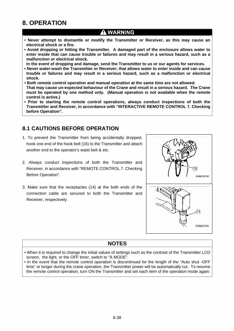
8. OPERATION
• Never attempt to dismantle or modify the Transmitter or Receiver, as this may cause an electrical shock or a fire.
• Avoid dropping or hitting the Transmitter. A damaged part of the enclosure allows water to enter inside that can cause trouble or failures and may result in a serious hazard, such as a malfunction or electrical shock. In the event of dropping and damage, send the Transmitter to us or our agents for services.
• Never water-wash the Transmitter or Receiver; that allows water to enter inside and can cause trouble or failures and may result in a serious hazard, such as a malfunction or electrical shock.
• Both remote control operation and manual operation at the same time are not allowed. That may cause un-expected behaviour of the Crane and result in a serious hazard. The Crane must be operated by one method only. (Manual operation is not available when the remote control is active.)
• Prior to starting the remote control operations, always conduct inspections of both the Transmitter and Receiver, in accordance with “INTERACTIVE REMOTE CONTROL 7. Checking before Operation”.
8.1 CAUTIONS BEFORE OPERATION
1. To prevent the Transmitter from being accidentally dropped,
hook one end of the hook belt (16) to the Transmitter and attach
another end to the operator’s waist belt & etc.
2. Always conduct inspections of both the Transmitter and
Receiver, in accordance with “REMOTE CONTROL 7. Checking
Before Operation”.
3. Make sure that the receptacles (14) at the both ends of the
connection cable are secured to both the Transmitter and
Receiver, respectively.
NOTES
• When it is required to change the initial values of settings such as the contrast of the Transmitter LCD screen, the light, or the OFF timer, switch to “A MODE”.
• In the event that the remote control operation is discontinued for the length of the “Auto shut -OFF time” or longer during the crane operation, the Transmitter power will be automatically cut. To resume the remote control operation, turn ON the Transmitter and set each item of the operation mode again.
6-38
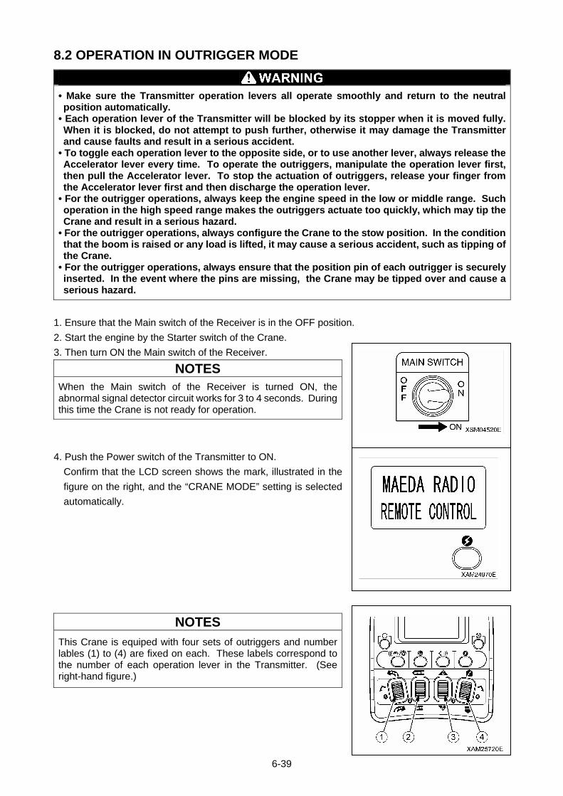
8.2 OPERATION IN OUTRIGGER MODE
• Make sure the Transmitter operation levers all operate smoothly and return to the neutral position automatically.
• Each operation lever of the Transmitter will be blocked by its stopper when it is moved fully. When it is blocked, do not attempt to push further, otherwise it may damage the Transmitter and cause faults and result in a serious accident.
• To toggle each operation lever to the opposite side, or to use another lever, always release the Accelerator lever every time. To operate the outriggers, manipulate the operation lever first, then pull the Accelerator lever. To stop the actuation of outriggers, release your finger from the Accelerator lever first and then discharge the operation lever.
• For the outrigger operations, always keep the engine speed in the low or middle range. Such operation in the high speed range makes the outriggers actuate too quickly, which may tip the Crane and result in a serious hazard.
• For the outrigger operations, always configure the Crane to the stow position. In the condition that the boom is raised or any load is lifted, it may cause a serious accident, such as tipping of the Crane.
• For the outrigger operations, always ensure that the position pin of each outrigger is securely inserted. In the event where the pins are missing, the Crane may be tipped over and cause a serious hazard.
1. Ensure that the Main switch of the Receiver is in the OFF position.
2. Start the engine by the Starter switch of the Crane.
3. Then turn ON the Main switch of the Receiver.
NOTES
When the Main switch of the Receiver is turned ON, the abnormal signal detector circuit works for 3 to 4 seconds. During this time the Crane is not ready for operation.
4. Push the Power switch of the Transmitter to ON.
Confirm that the LCD screen shows the mark, illustrated in the
figure on the right, and the “CRANE MODE” setting is selected
automatically.
NOTES
This Crane is equiped with four sets of outriggers and number lables (1) to (4) are fixed on each. These labels correspond to the number of each operation lever in the Transmitter. (See right-hand figure.)
6-39
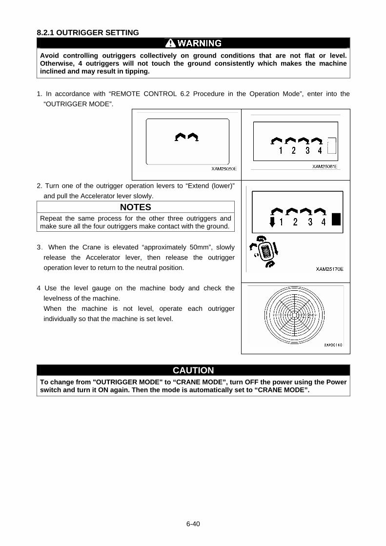
8.2.1 OUTRIGGER SETTING
Avoid controlling outriggers collectively on ground conditions that are not flat or level. Otherwise, 4 outriggers will not touch the ground consistently which makes the machine inclined and may result in tipping.
1. In accordance with “REMOTE CONTROL 6.2 Procedure in the Operation Mode”, enter into the
“OUTRIGGER MODE”.
2. Turn one of the outrigger operation levers to “Extend (lower)”
and pull the Accelerator lever slowly.
NOTES
Repeat the same process for the other three outriggers and make sure all the four outriggers make contact with the ground.
3.When the Crane is elevated “approximately 50mm”, slowly
release the Accelerator lever, then release the outrigger
operation lever to return to the neutral position.
4 Use the level gauge on the machine body and check the
levelness of the machine.
When the machine is not level, operate each outrigger
individually so that the machine is set level.
CAUTION To change from "OUTRIGGER MODE" to “CRANE MODE”, turn OFF the power using the Power switch and turn it ON again. Then the mode is automatically set to “CRANE MODE”.
6-40
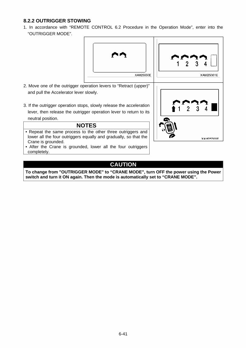
8.2.2 OUTRIGGER STOWING 1. In accordance with “REMOTE CONTROL 6.2 Procedure in the Operation Mode”, enter into the
“OUTRIGGER MODE”.
2. Move one of the outrigger operation levers to “Retract (upper)”
and pull the Accelerator lever slowly.
3. If the outrigger operation stops, slowly release the acceleration
lever, then release the outrigger operation lever to return to its
neutral position.
NOTES • Repeat the same process to the other three outriggers and lower all the four outriggers equally and gradually, so that the Crane is grounded.
• After the Crane is grounded, lower all the four outriggers completely.
CAUTION To change from "OUTRIGGER MODE" to “CRANE MODE”, turn OFF the power using the Power switch and turn it ON again. Then the mode is automatically set to “CRANE MODE”.
6-41
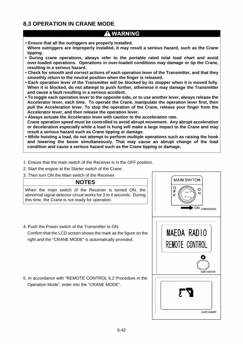
8.3 OPERATION IN CRANE MODE
• Ensure that all the outriggers are properly installed. Where outriggers are improperly installed, it may result a serious hazard, such as the Crane tipping.
• During crane operations, always refer to the portable rated total load chart and avoid over-loaded operations. Operations in over-loaded conditions may damage or tip the Crane, resulting in a serious hazard.
• Check for smooth and correct actions of each operation lever of the Transmitter, and that they smoothly return to the neutral position when the finger is released.
• Each operation lever of the Transmitter will be blocked by its stopper when it is moved fully. When it is blocked, do not attempt to push further, otherwise it may damage the Transmitter and cause a fault resulting in a serious accident.
• To toggle each operation lever to the opposite side, or to use another lever, always release the Accelerator lever, each time. To operate the Crane, manipulate the operation lever first, then pull the Acceleration lever. To stop the operation of the Crane, release your finger from the Accelerator lever, and then release the operation lever.
• Always actuate the Accelerator lever with caution to the acceleration rate. Crane operation speed must be controlled to avoid abrupt movement. Any abrupt acceleration or deceleration especially while a load is hung will make a large impact to the Crane and may result a serious hazard such as Crane tipping or damage.
• While hoisting a load, do not attempt to perform multiple operations such as raising the hook and lowering the boom simultaneously. That may cause an abrupt change of the load condition and cause a serious hazard such as the Crane tipping or damage.
1. Ensure that the main switch of the Receiver is in the OFF position.
2. Start the engine at the Starter switch of the Crane.
3. Then turn ON the Main switch of the Receiver.
NOTES
When the main switch of the Receiver is turned ON, the abnormal signal detector circuit works for 3 to 4 seconds. During this time, the Crane is not ready for operation.
4. Push the Power switch of the Transmitter to ON.
Confirm that the LCD screen shows the mark as the figure on the
right and the “CRANE MODE” is automatically provided.
5. In accordance with “REMOTE CONTROL 6.2 Procedure in the
Operation Mode”, enter into the “CRANE MODE”.
6-42
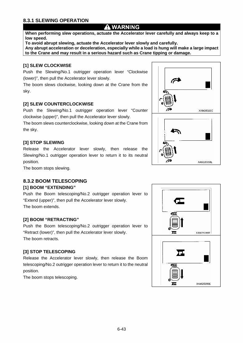
8.3.1 SLEWING OPERATION
When performing slew operations, actuate the Accelerator lever carefully and always keep to a low speed. To avoid abrupt slewing, actuate the Accelerator lever slowly and carefully. Any abrupt acceleration or deceleration, especially while a load is hung will make a large impact to the Crane and may result in a serious hazard such as Crane tipping or damage.
[1] SLEW CLOCKWISE
Push the Slewing/No.1 outrigger operation lever “Clockwise
(lower)”, then pull the Accelerator lever slowly.
The boom slews clockwise, looking down at the Crane from the
sky.
[2] SLEW COUNTERCLOCKWISE
Push the Slewing/No.1 outrigger operation lever “Counter
clockwise (upper)”, then pull the Accelerator lever slowly.
The boom slews counterclockwise, looking down at the Crane from
the sky.
[3] STOP SLEWING
Release the Accelerator lever slowly, then release the
Slewing/No.1 outrigger operation lever to return it to its neutral
position.
The boom stops slewing.
8.3.2 BOOM TELESCOPING [1] BOOM “EXTENDING”
Push the Boom telescoping/No.2 outrigger operation lever to
“Extend (upper)”, then pull the Accelerator lever slowly.
The boom extends.
[2] BOOM “RETRACTING”
Push the Boom telescoping/No.2 outrigger operation lever to
“Retract (lower)”, then pull the Accelerator lever slowly.
The boom retracts.
[3] STOP TELESCOPING
Release the Accelerator lever slowly, then release the Boom
telescoping/No.2 outrigger operation lever to return it to the neutral
position.
The boom stops telescoping.
6-43
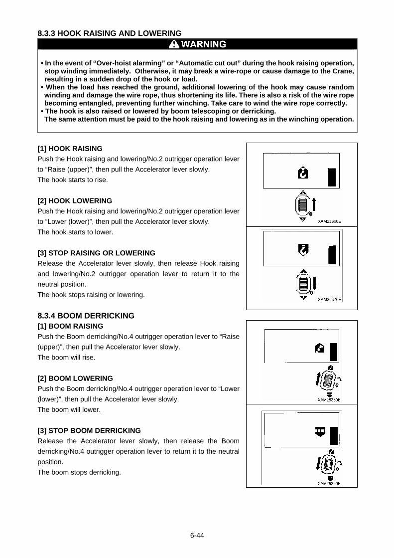
8.3.3 HOOK RAISING AND LOWERING
• In the event of “Over-hoist alarming” or “Automatic cut out” during the hook raising operation, stop winding immediately. Otherwise, it may break a wire-rope or cause damage to the Crane, resulting in a sudden drop of the hook or load.
• When the load has reached the ground, additional lowering of the hook may cause random winding and damage the wire rope, thus shortening its life. There is also a risk of the wire rope becoming entangled, preventing further winching. Take care to wind the wire rope correctly.
• The hook is also raised or lowered by boom telescoping or derricking. The same attention must be paid to the hook raising and lowering as in the winching operation.
[1] HOOK RAISING
Push the Hook raising and lowering/No.2 outrigger operation lever
to “Raise (upper)”, then pull the Accelerator lever slowly.
The hook starts to rise.
[2] HOOK LOWERING
Push the Hook raising and lowering/No.2 outrigger operation lever
to “Lower (lower)”, then pull the Accelerator lever slowly.
The hook starts to lower.
[3] STOP RAISING OR LOWERING
Release the Accelerator lever slowly, then release Hook raising
and lowering/No.2 outrigger operation lever to return it to the
neutral position.
The hook stops raising or lowering.
8.3.4 BOOM DERRICKING [1] BOOM RAISING
Push the Boom derricking/No.4 outrigger operation lever to “Raise
(upper)”, then pull the Accelerator lever slowly.
The boom will rise.
[2] BOOM LOWERING
Push the Boom derricking/No.4 outrigger operation lever to “Lower
(lower)”, then pull the Accelerator lever slowly.
The boom will lower.
[3] STOP BOOM DERRICKING
Release the Accelerator lever slowly, then release the Boom
derricking/No.4 outrigger operation lever to return it to the neutral
position.
The boom stops derricking.
6-44
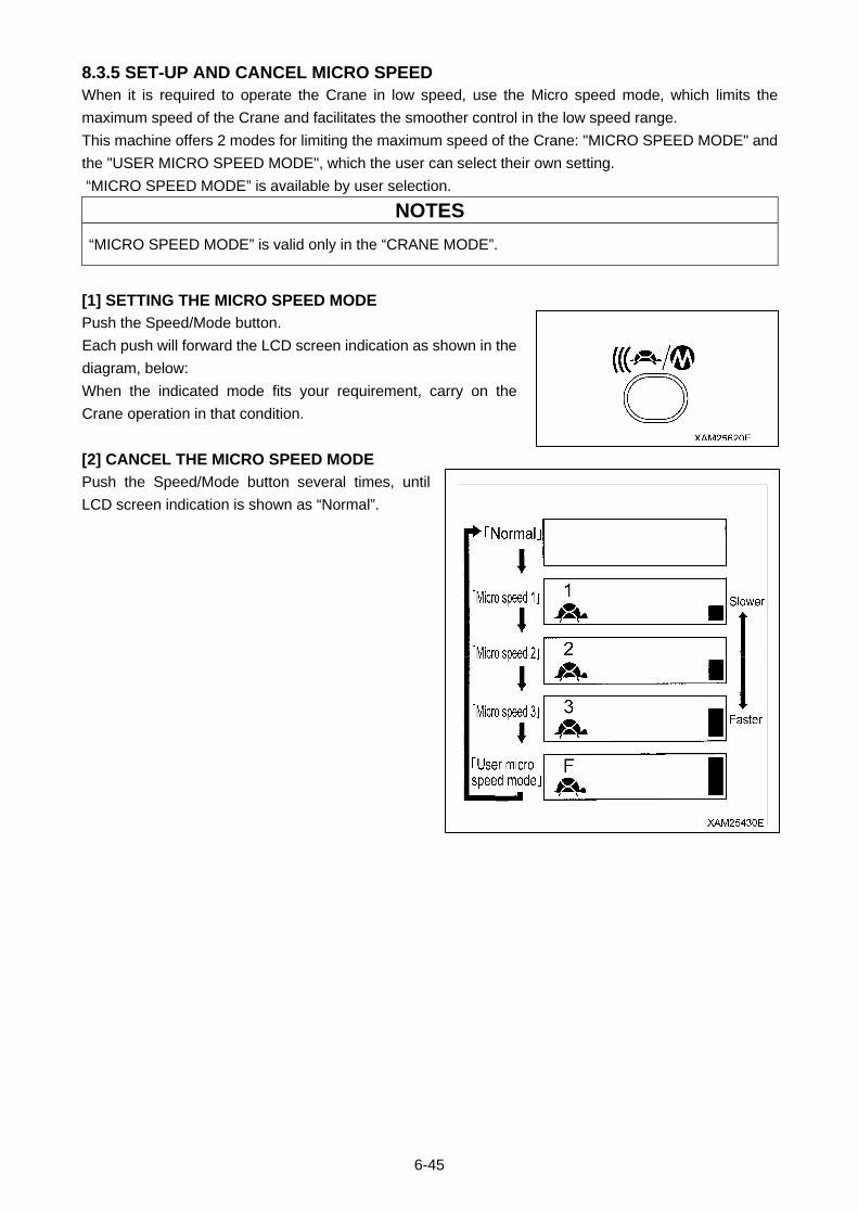
8.3.5 SET-UP AND CANCEL MICRO SPEED When it is required to operate the Crane in low speed, use the Micro speed mode, which limits the
maximum speed of the Crane and facilitates the smoother control in the low speed range.
This machine offers 2 modes for limiting the maximum speed of the Crane: "MICRO SPEED MODE" and
the "USER MICRO SPEED MODE", which the user can select their own setting.
“MICRO SPEED MODE” is available by user selection.
NOTES
“MICRO SPEED MODE” is valid only in the “CRANE MODE”.
[1] SETTING THE MICRO SPEED MODE
Push the Speed/Mode button.
Each push will forward the LCD screen indication as shown in the
diagram, below:
When the indicated mode fits your requirement, carry on the
Crane operation in that condition.
[2] CANCEL THE MICRO SPEED MODE
Push the Speed/Mode button several times, until
LCD screen indication is shown as “Normal”.
6-45
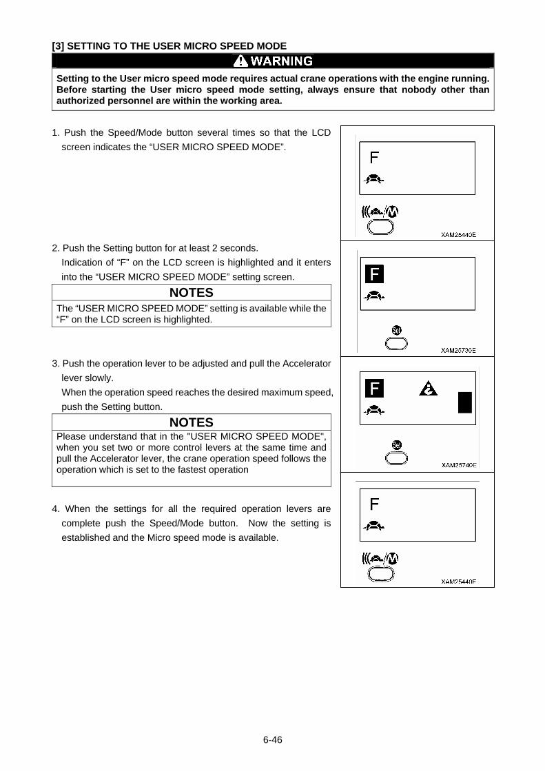
[3] SETTING TO THE USER MICRO SPEED MODE
Setting to the User micro speed mode requires actual crane operations with the engine running. Before starting the User micro speed mode setting, always ensure that nobody other than authorized personnel are within the working area.
1. Push the Speed/Mode button several times so that the LCD
screen indicates the “USER MICRO SPEED MODE”.
2. Push the Setting button for at least 2 seconds.
Indication of “F” on the LCD screen is highlighted and it enters
into the “USER MICRO SPEED MODE” setting screen.
NOTES
The “USER MICRO SPEED MODE” setting is available while the “F” on the LCD screen is highlighted.
3. Push the operation lever to be adjusted and pull the Accelerator
lever slowly.
When the operation speed reaches the desired maximum speed,
push the Setting button.
NOTES Please understand that in the "USER MICRO SPEED MODE", when you set two or more control levers at the same time and pull the Accelerator lever, the crane operation speed follows the operation which is set to the fastest operation
4. When the settings for all the required operation levers are
complete push the Speed/Mode button. Now the setting is
established and the Micro speed mode is available.
6-46
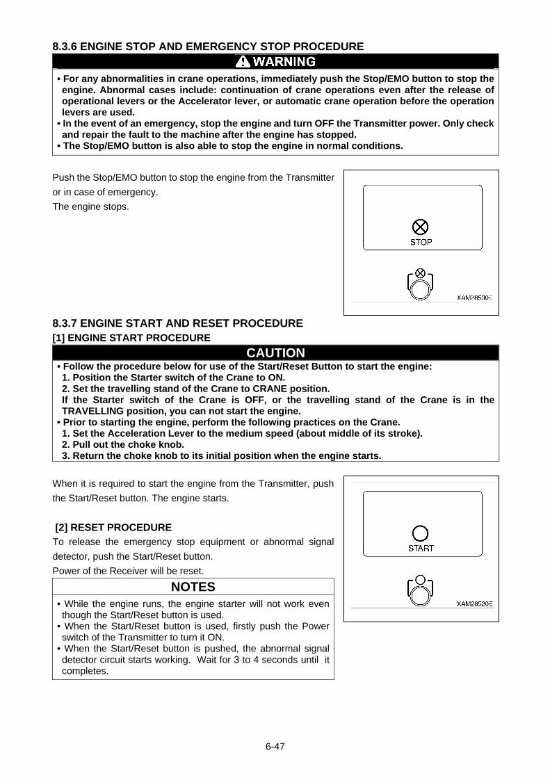
8.3.6 ENGINE STOP AND EMERGENCY STOP PROCEDURE
• For any abnormalities in crane operations, immediately push the Stop/EMO button to stop the engine. Abnormal cases include: continuation of crane operations even after the release of operational levers or the Accelerator lever, or automatic crane operation before the operation levers are used.
• In the event of an emergency, stop the engine and turn OFF the Transmitter power. Only check and repair the fault to the machine after the engine has stopped.
• The Stop/EMO button is also able to stop the engine in normal conditions.
Push the Stop/EMO button to stop the engine from the Transmitter
or in case of emergency.
The engine stops.
8.3.7 ENGINE START AND RESET PROCEDURE [1] ENGINE START PROCEDURE
CAUTION • Follow the procedure below for use of the Start/Reset Button to start the engine: 1. Position the Starter switch of the Crane to ON. 2. Set the travelling stand of the Crane to CRANE position. If the Starter switch of the Crane is OFF, or the travelling stand of the Crane is in the TRAVELLING position, you can not start the engine.
• Prior to starting the engine, perform the following practices on the Crane. 1. Set the Acceleration Lever to the medium speed (about middle of its stroke). 2. Pull out the choke knob. 3. Return the choke knob to its initial position when the engine starts.
When it is required to start the engine from the Transmitter, push
the Start/Reset button. The engine starts.
[2] RESET PROCEDURE
To release the emergency stop equipment or abnormal signal
detector, push the Start/Reset button.
Power of the Receiver will be reset.
NOTES
• While the engine runs, the engine starter will not work even though the Start/Reset button is used.
• When the Start/Reset button is used, firstly push the Power switch of the Transmitter to turn it ON.
• When the Start/Reset button is pushed, the abnormal signal detector circuit starts working. Wait for 3 to 4 seconds until it completes.
6-47
8.4 CHECKING AFTER CRANE OPERATION
• When the operation of the Crane is finished, always turn OFF the Transmitter and Receiver power.
• On no occasion except for Crane operations, must the power of the Transmitter be turned ON. This could cause unexpected movement of the Crane resulting in a serious hazard, such that the Crane hitting someone or an object, or the Crane could tip.
• When it is required to turn ON the Transmitter for the purpose of inspection or such, ensure first that the engne is not running, then shut down the Receiver by turning OFF its main switch.
1. Enter into the “CRANE MODE” of the Transmitter operation mode.
2. Use the operation levers and retract the boom to its shortest condition and lower it to the base position.
NOTES
Stowing the hook block is available only by using the control lever and switch on the crane.
3. Enter into the “OUTRIGGER MODE” of the Transmitter operation mode.
4. Use the operation levers and stow all the outriggers so that the Crane is configured to the travelling
position.
5. Stop the engine and turn OFF the Transmitter power.
6. Shut down the power of the Receiver by turning its Main switch to the OFF position.
7. Maintain the Transmitter and Receiver as follows:
(1) Check operation levers and the Accelerator lever for any faults.
(2) Remove oil or dirt with a clean cloth.
(3) Repair all cracks or damages without fail.
8. Put the transmitter into the accessory storage case and keep it in the dry and cool place where the wind
and rain or direct sun light is sheltered.
6-48

9. TROUBLE SHOOTING
9.1 BEFORE TROUBLE SHOOTING
“While the Crane operates perfectly under manual control, part or whole functions are inoperable from the
remote control.”
In the event of failure as above, perform the DIAGNOSIS shown in the following pages.
CAUTION First, check in accordance with the table below before you start the diagnosis, based on the following pages. Such an error may be occasionally fixed by simple practice, such as applying another operation procedure. If the fault persists, contact us or our agents for services.
Check Points Cause and Action
The Crane is operable under the manual control from the Crane.
When the Crane operates, this remote control device has a failure. Otherwise, if the Crane does not operate, perform diagnosis of the Crane.
Power of the Transmitter and Receiver is ON. If not, turn ON the power.
The fuse in the Receiver is blown. Check whether the fuse is blown or not; check the cause when blown, then replace with a new one.
The Transmitter enclosure is deformed or damaged.
Where the Transmitter enclosure is deformed or damaged, repair or replace it.
Each operation lever of the Transmitter is in its neutral position. The Accelerator lever is completely returned.
In any event of operation levers or control button failure, repair or replace.
Manipulation began just after the Power switch of the Transmitter is turned ON.
Allow 3 to 4 seconds after the Transmitter power is turned ON, with no operations.
The LCD screen in the Transmitter or the Monitor display in the Receiver shows error massages or error codes.
In the event where the error massages or error codes are indicated, first power OFF the Transmitter and turn it ON again.
6-49

9.2 ERRORS IN THE REMOTE CONTROL DEVICES.
• When diagnosing the error, always verify on the monitor display of the Receiver and the LCD screen on
the Transmitter. Then, match the error with a suitable description from the table below.
• First, perform the “Remedy 1” in the table, then continue to “Remedy 2” if the error persists.
• Remedies marked with - You must contact us or our service agents.
• When any other causes are suspected, other than listed below, contact us or our service agents.
Error display Remedy
Transmitter Receiver Main cause
Remedy 1 Remedy 2 Receiver printed circuit board (PCB) input voltage dropped. • Relay PCB defective. • Power line wire harness defective between relay PCB and Receiver PCB.
Maintenance/replace for Receiver printed circuit board (PCB) or internal wiring
―――
――
Receiver PCB defective Maintenance/replace
for Receiver printed circuit board (PCB)
―――
Disconnection of the cable. • Communication data from Moment limiter is not received by receiver.
• Turn off main switch once, and turn it on again.
Maintenance/replace for the cable between the Moment limiter display unit and the Receiver.
STOP
The Transmitter is in emergency stop
• Use the Reset button to release the emerge- ncy stop.
Maintenance/replace for Receiver and Transmitter
The Transmitter defective • The Transmitter power is not ON.
• The Transmitter PCB defect- ive.
• Wire cut in the Connection cable.
• Power ON again the
Transmitter Maintenance/replace
for Transmitter Maintenance/replace
for Transmitter
Maintenance/replace for Transmitter
―――
The Receiver defective. • The Receiver PCB defective. • Wiring problem in the Receiver
Maintenance/replace for Transmitter
E3
The Transmitter defective • Wire cut within accelerator section in the Transmitter, or potentiometer failure.
Maintenance/replace for Transmitter
―――
The Transmitter defective • The potentiometer for accele- rator lever in the transmitter failed during receiving signal.
• A control lever switch in the transmitter failed during recei- ving signal.
• Release the Control Lever or Accelerator Lever, and push Power Switch.
Maintenance/replace for Transmitter
―――
The Receiver PCB defective • Data error in the memory.
• Power on the Receiver, again.
Maintenance/replace for Receiver
E6
The Transmitter defective • Data error in the memory.
• Power on the Transmitter, again.
Maintenance/replace for Transmitter
E4
The Receiver defective • Accelerator Lever of the Trans- mitter was pulled when the power is turned ON.
• Release the Accele- rator Lever and push Power Switch.
Maintenance/replace for Transmitter
E9
The Transmitter defective • Any control lever in the Trans- mitter was not return to neutral position when the power is turned ON.
• Release the Control Lever, and push Power Switch.
Maintenance/replace for Transmitter
6-50
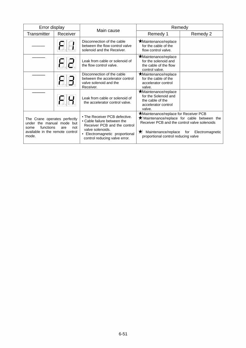
Error display Remedy
Transmitter Receiver Main cause
Remedy 1 Remedy 2
―――
Disconnection of the cable between the flow control valve solenoid and the Receiver.
Maintenance/replace for the cable of the flow control valve.
―――
Leak from cable or solenoid of the flow control valve.
Maintenance/replace for the solenoid and the cable of the flow control valve.
―――
Disconnection of the cable between the accelerator control valve solenoid and the Receiver.
Maintenance/replace for the cable of the accelerator control valve.
―――
Leak from cable or solenoid of the accelerator control valve.
Maintenance/replace for the Solenoid and the cable of the accelerator control valve.
The Crane operates perfectly under the manual mode but some functions are not available in the remote control mode.
• The Receiver PCB defective. • Cable failure between the
Receiver PCB and the control valve solenoids.
• Electromagnetic proportional control reducing valve error.
Maintenance/replace for Receiver PCB Maintenance/replace for cable between the
Receiver PCB and the control valve solenoids
Maintenance/replace for Electromagnetic proportional control reducing valve
6-51

6-52
10. SYSTEM SPCIFICATIONS Items MCT300N
Waterproof protection IP65
System configuration Manual and Remote control, both-way
Operation monitor LCD monitor panel • Operation status monitor • Message • Error code
Emergency stop equipment
Abnormal signal detector unit at the engine start
Automatic power cut unit (Automatic Power-OFF)
Voltage drop limiter
Safety devices
Warning switch
Receiver unit voltage Power for the Crane (DC 12V)
Receiver unit power consumption Approximately 70 watts (maximum, per single function)
Operating ambient temperature -10°C to +60°C
Storage ambient temperature -20°C to +70°C
Transmitter weight 600g
Boom raise/lower Raising and lowering
Hook raise/lower Raising and lowering
Boom telescoping Extending and retracting Lever switches
Slewing Counterclockwise/clockwise
Power ON/OFF
Horn Warning signal
Setting Mode setting
Speed/Mode Speed control/Mode selection
Start/Reset Engine start/Reset
Push button switches
Stop/EMO Engine stop/Emergency stop
Transm
itter functions
Trigger type accelerator Hydraulic control + Engine control

ENGINE AND ELECTRIC MOTOR SPECIFICATIONS
1. PRECAUTIONS (FOR ENGINE AND ELECTRIC MOTOR SPECIFICATION) 7- 2
2. SAFETY LABEL LOCATIONS 7- 3
3. MACHINE EACH SECTION 7- 5
4. OPERATION 7-12
5. LONG-TERM STORAGE 7-19
6. ELECTRIC MOTOR TROUBLESHOOTING 7-20
7. PRINCIPLE SPECIFICATION LIST 7-21
8. SPECIFICATION DIMENSINAL DRAWING 7-22
9. DIMENSIONAL DRAWING OF OUTRIGGER WIDTH 7-23
7-1
1. PRECAUTIONS (FOR ENGINE AND ELECTRIC MOTOR SPECIFICATION)
The following precautions should always be observed when using this machine. If these, or the engine and electric motor specifications are disregarded, a serious accident may occur. • Installation of this machine must comply with laws and regulations of your country. Contact us or our sales service agency if no laws and regulations are applied.
• Only personnel qualified according to laws and regulations of your country are allowed to establish power connection of the power supply equipment or inspect and repair the electric system. Contact us or our sales service agency if no laws and regulations are applied.
• Operation and storage of this machine must satisfy the requirements listed below: • Operating temperature: -10 to 40°C (no frost) • Storage temperature: -20 to 60°C • Operating humidity: Max. 90%RH (no condensation) • Atmosphere: Outdoor environment free from explosive, flammable, and corrosive gases, moisture, and excessive dust particles
• Altitude: Max. 1000m • Vibration: Max. 0.5G • Turn OFF the power supply equipment breaker promptly in the event of anything abnormal on the machine during operation. The potential of fire or an electric shock may occur if disregarded.
• Turn OFF the power supply equipment breaker promptly in the event of a power failure during operation, otherwise the machine may inadvertantly operate upon energization.
• Always turn OFF the power supply equipment breaker before performing inspection and maintenance of the electric system. The potential of a electric shock may occur during work if disregarded. Before inspection and maintenance, inform all personnel to alert them of your action. Be sure to attach a warning tag, “Do Not Touch”, to the power supply equipment breaker for the prevention of accidental breaker operation conducted by other personnel.
• Always turn OFF the power supply equipment breaker and wait for at least 10 minutes before performing inspection and maintenance of the electric system. Ensure that no voltage is applied to the power supply box with a tester.
• All the parts will be at elevated temperatures immediately after machine operation. For safety only perform inspection and maintenance of the electric system according to the procedure provided in this manual and only after the parts drop in temperature. Potential burns may occur if disregarded.
• Keep the power supply box and inverter board away from water. The machine may malfunction if the electric system is wet. Exercise due caution when handling the electric system.
• Contact us or our sales service agency to request repair of the inside of the inverter board, when necessary.
CAUTION See “Safety” for safety precautions that are not provided in this section. The weight (mass) of a machine varies with machine types between a standard specification machine and a machine fitted with both engine and electric motor specifications. See the following figure for the weight (mass) of the machine described in “Safety 2.3 WORKING WITH CRANE”.
7-2
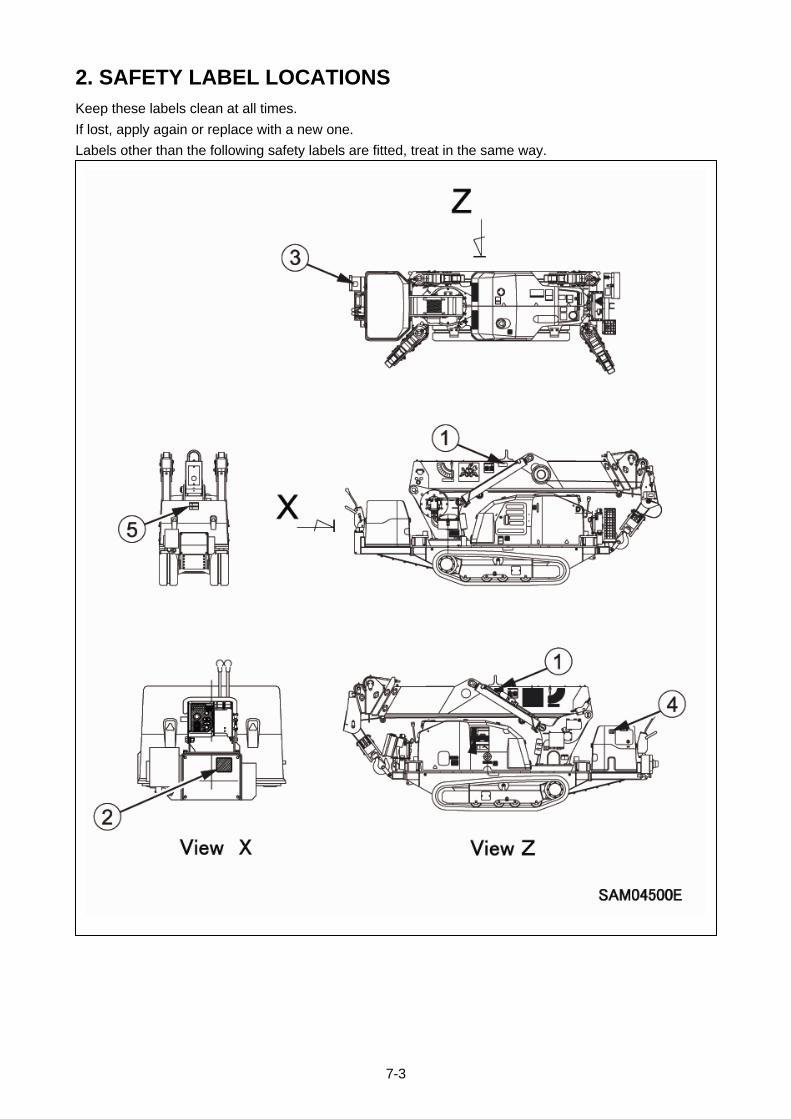
2. SAFETY LABEL LOCATIONS Keep these labels clean at all times.
If lost, apply again or replace with a new one.
Labels other than the following safety labels are fitted, treat in the same way.
7-3
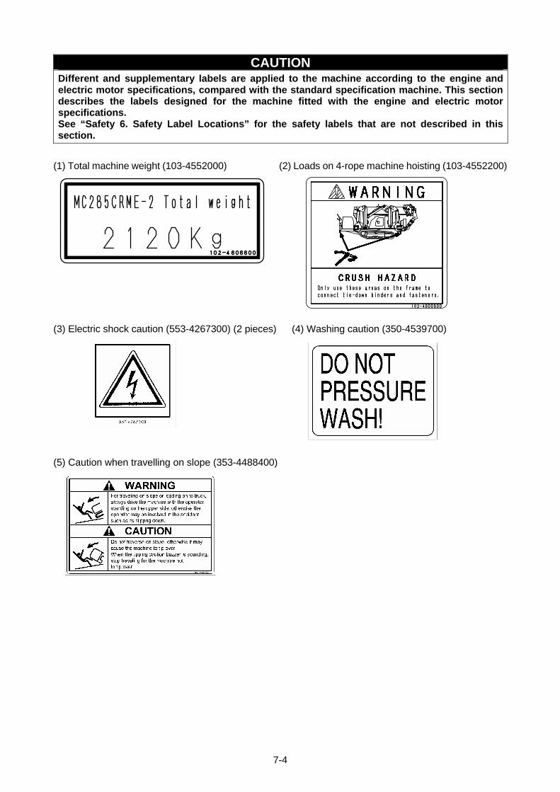
CAUTION Different and supplementary labels are applied to the machine according to the engine and electric motor specifications, compared with the standard specification machine. This section describes the labels designed for the machine fitted with the engine and electric motor specifications. See “Safety 6. Safety Label Locations” for the safety labels that are not described in this section.
(1) Total machine weight (103-4552000) (2) Loads on 4-rope machine hoisting (103-4552200)
(3) Electric shock caution (553-4267300) (2 pieces) (4) Washing caution (350-4539700)
(5) Caution when travelling on slope (353-4488400)
7-4
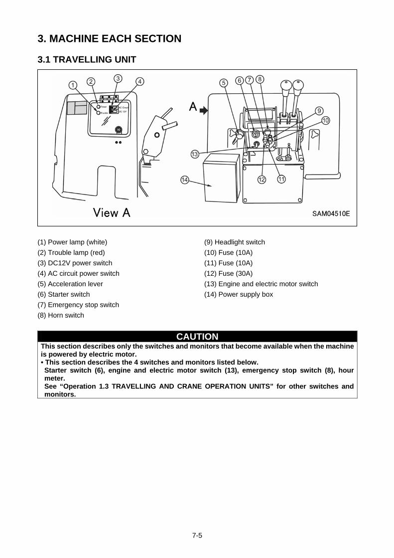
3. MACHINE EACH SECTION
3.1 TRAVELLING UNIT
(1) Power lamp (white) (9) Headlight switch
(2) Trouble lamp (red) (10) Fuse (10A)
(3) DC12V power switch (11) Fuse (10A)
(4) AC circuit power switch (12) Fuse (30A)
(5) Acceleration lever (13) Engine and electric motor switch
(6) Starter switch (14) Power supply box
(7) Emergency stop switch
(8) Horn switch
CAUTION This section describes only the switches and monitors that become available when the machine is powered by electric motor. • This section describes the 4 switches and monitors listed below. Starter switch (6), engine and electric motor switch (13), emergency stop switch (8), hour meter. See “Operation 1.3 TRAVELLING AND CRANE OPERATION UNITS” for other switches and monitors.
7-5
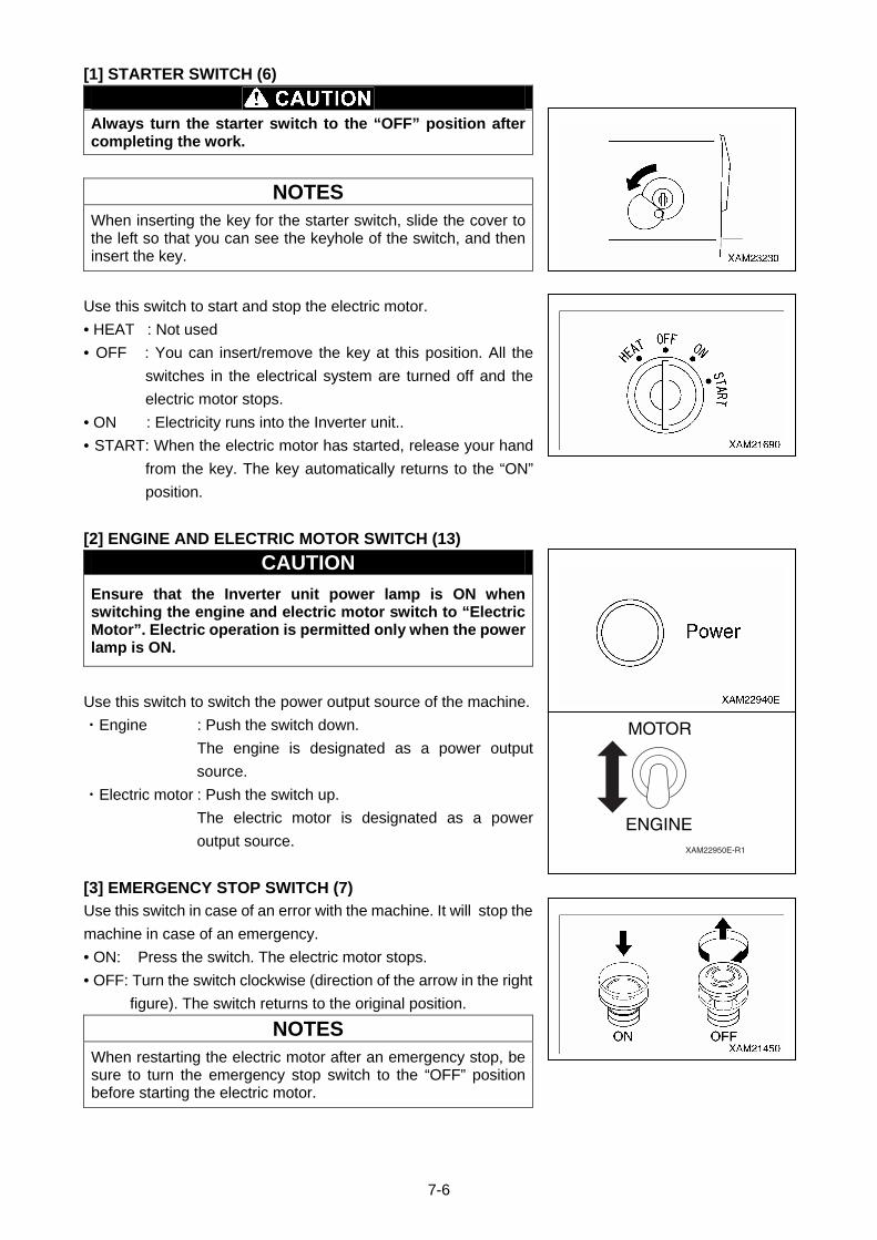
[1] STARTER SWITCH (6)
Always turn the starter switch to the “OFF” position after completing the work.
NOTES
When inserting the key for the starter switch, slide the cover to the left so that you can see the keyhole of the switch, and then insert the key.
Use this switch to start and stop the electric motor.
• HEAT : Not used
• OFF : You can insert/remove the key at this position. All the
switches in the electrical system are turned off and the
electric motor stops.
• ON : Electricity runs into the Inverter unit..
• START: When the electric motor has started, release your hand
from the key. The key automatically returns to the “ON”
position.
[2] ENGINE AND ELECTRIC MOTOR SWITCH (13)
CAUTION
Ensure that the Inverter unit power lamp is ON when switching the engine and electric motor switch to “Electric Motor”. Electric operation is permitted only when the power lamp is ON.
Use this switch to switch the power output source of the machine.
・Engine : Push the switch down.
The engine is designated as a power output
source.
・Electric motor : Push the switch up.
The electric motor is designated as a power
output source.
[3] EMERGENCY STOP SWITCH (7)
Use this switch in case of an error with the machine. It will stop the
machine in case of an emergency.
• ON: Press the switch. The electric motor stops.
• OFF: Turn the switch clockwise (direction of the arrow in the right
figure). The switch returns to the original position.
NOTES
When restarting the electric motor after an emergency stop, be sure to turn the emergency stop switch to the “OFF” position before starting the electric motor.
MOTOR
ENGINEXAM22950E-R1
7-6

[4] HOUR METER
This meter shows the total running hours of the machine.
Use this value as the reference for periodical check intervals.
With the power lamp of the Inverter unit ON, the meter gives
continuous readings upon switching the engine and electric motor
switch to “Electric Motor” and turning the starter switch to the ON
position, even if the electric motor and machine are at a halt.
The meter indication advances “1” when the machine has been
running for 1 hour regardless of the engine rotation speed.
7-7
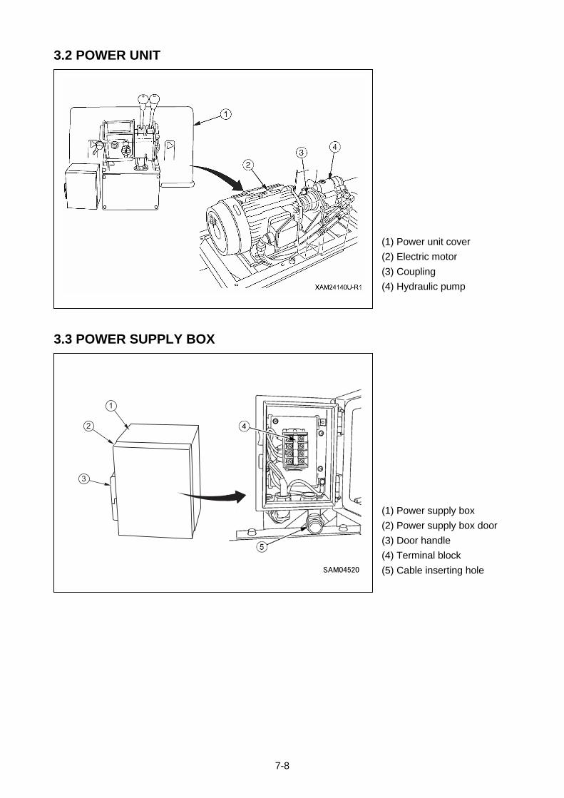
3.2 POWER UNIT
(1) Power unit cover
(2) Electric motor
(3) Coupling
(4) Hydraulic pump
3.3 POWER SUPPLY BOX
(1) Power supply box
(2) Power supply box door
(3) Door handle
(4) Terminal block
(5) Cable inserting hole
7-8
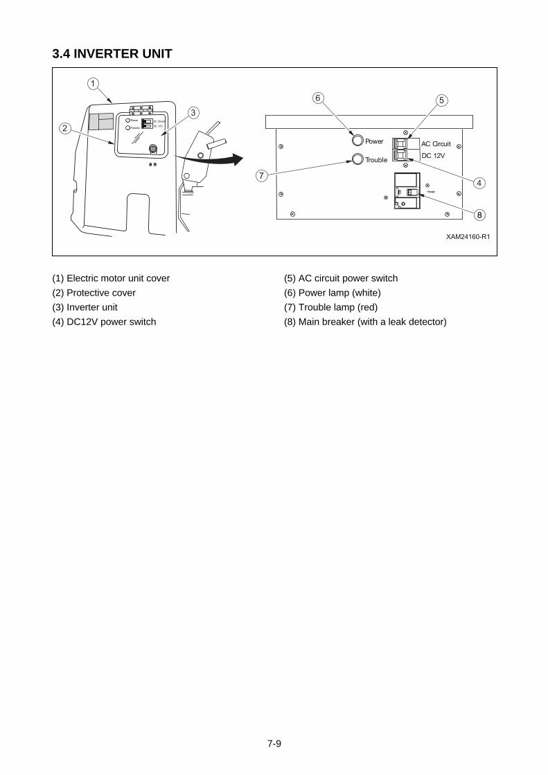
3.4 INVERTER UNIT
(1) Electric motor unit cover (5) AC circuit power switch
(2) Protective cover (6) Power lamp (white)
(3) Inverter unit (7) Trouble lamp (red)
(4) DC12V power switch (8) Main breaker (with a leak detector)
7-9
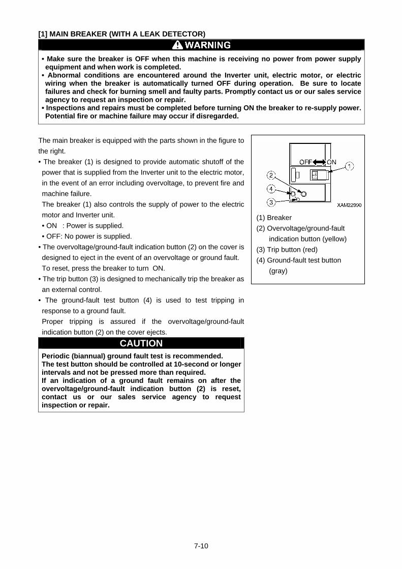
[1] MAIN BREAKER (WITH A LEAK DETECTOR)
• Make sure the breaker is OFF when this machine is receiving no power from power supply equipment and when work is completed.
• Abnormal conditions are encountered around the Inverter unit, electric motor, or electric wiring when the breaker is automatically turned OFF during operation. Be sure to locate failures and check for burning smell and faulty parts. Promptly contact us or our sales service agency to request an inspection or repair.
• Inspections and repairs must be completed before turning ON the breaker to re-supply power.Potential fire or machine failure may occur if disregarded.
The main breaker is equipped with the parts shown in the figure to
the right.
• The breaker (1) is designed to provide automatic shutoff of the
power that is supplied from the Inverter unit to the electric motor,
in the event of an error including overvoltage, to prevent fire and
machine failure.
The breaker (1) also controls the supply of power to the electric
motor and Inverter unit. (1) Breaker
(2) Overvoltage/ground-fault
indication button (yellow)
(3) Trip button (red)
(4) Ground-fault test button
(gray)
• ON : Power is supplied.
• OFF: No power is supplied.
• The overvoltage/ground-fault indication button (2) on the cover is
designed to eject in the event of an overvoltage or ground fault.
To reset, press the breaker to turn ON.
• The trip button (3) is designed to mechanically trip the breaker as
an external control.
• The ground-fault test button (4) is used to test tripping in
response to a ground fault.
Proper tripping is assured if the overvoltage/ground-fault
indication button (2) on the cover ejects.
CAUTION Periodic (biannual) ground fault test is recommended. The test button should be controlled at 10-second or longer intervals and not be pressed more than required. If an indication of a ground fault remains on after the overvoltage/ground-fault indication button (2) is reset, contact us or our sales service agency to request inspection or repair.
7-10

[2] DC12V POWER SWITCH
The DC12V power switch is used to switch the DC power output
source for the crane operation system.
• ON: Power is supplied to the crane operation system.
• OFF: No power is supplied to the crane operation system.
[3] AC CIRCUIT POWER SWITCH
The AC circuit power switch is used to switch the AC power output
source for the Inverter unit and inverter cooling fan.
• ON: Power is supplied to the Inverter unit and inverter cooling
fan.
• OFF: No power is supplied to the Inverter unit and inverter cooling
fan.
NOTES • No safety hazard is posed even if the DC12V power switch and AC circuit power switch remain on.
• The AC circuit power switch is illustrated in the upper figure to the right, and the DC12V power switch is illustrated in the lower figure.
[4] POWER LAMP (WHITE)
The power lamp is designed to indicate the presence of
energization to this machine from power supply equipment.
• ON: This machine is receiving power from power supply
equipment.
• OFF: This machine is not receiving power from power supply
equipment.
NOTES
If the power lamp remains off despite the power supply equipment breaker being turned ON with power supply assured between power supply equipment and this machine, check the power supply on power supply equipment.
[5] TROUBLE LAMP (RED)
The Trouble lamp (Red) will turn ON when An error occurs in the Inverter unit. Contact us or our sales service agency to request inspection or repair in this event.
The trouble lamp is designed to indicate the presence of an error in
the Inverter unit.
• ON: An error is detected in the Inverter unit.
• OFF: The Inverter unit is in normal operation.
7-11
4. OPERATION
4.1 CHECKING BEFORE OPERATION
4.1.1 CHECKING BEFORE STARTING ELECTRIC MOTOR (VISIBLE CHECKS)
For details of checking before starting engine (visible checks), see “Operation 2.1.1 visible checks”. As to the machine conforming to engine and electric motor specifications, potential fire in the machine may occur if flammable materials and oil leaks are present around the hot sections such as the Inverter unit, power supply box, and power unit. Carefully check around these areas. If there is any abnormality, be sure to fix it or contact us or our sales service agency.
4.1.2 CHECKING BEFORE STARTING ELECTRIC MOTOR
CAUTION For details of checking before starting electric motor, see “Operation 2.1.2 Checking Before Starting Engine”.
4.1.3 CHECKING AFTER STARTING ELECTRIC MOTOR
CAUTION For details of checking after starting electric motor, see “Operation 2.1.3 Checking After Starting Engine”.
7-12
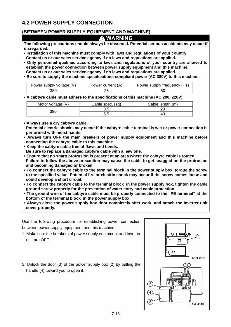
4.2 POWER SUPPLY CONNECTION
(BETWEEN POWER SUPPLY EQUIPMENT AND MACHINE)
The following precautions should always be observed. Potential serious accidents may occur if disregarded. • Installation of this machine must comply with laws and regulations of your country. Contact us or our sales service agency if no laws and regulations are applied.
• Only personnel qualified according to laws and regulations of your country are allowed to establish the power connection between power supply equipment and this machine. Contact us or our sales service agency if no laws and regulations are applied.
• Be sure to supply the machine specifications-compliant power (AC 380V) to this machine.
• A cabtyre cable must adhere to the specifications of this machine (AC 200, 220V).
• Always use a dry cabtyre cable. Potential electric shocks may occur if the cabtyre cable terminal is wet or power connection is performed with moist hands.
• Always turn OFF the main breakers of power supply equipment and this machine before connecting the cabtyre cable to this machine.
• Keep the cabtyre cable free of flaws and bends. Be sure to replace a damaged cabtyre cable with a new one.
• Ensure that no sharp protrusion is present at an area where the cabtyre cable is routed. Failure to follow the above precaution may cause the cable to get snagged on the protrusion and becoming damaged or broken.
• To connect the cabtyre cable to the terminal block in the power supply box, torque the screw to the specified value. Potential fire or electric shock may occur if the screw comes loose and could develop a short circuit.
• To connect the cabtyre cable to the terminal block in the power supply box, tighten the cable ground screw properly for the prevention of water entry and cable protection.
• The ground wire of the cabtyre cable must be properly connected to the “PE terminal” at the bottom of the terminal block in the power supply box.
• Always close the power supply box door completely after work, and attach the Inverter unit cover properly.
Use the following procedure for establishing power connection
between power supply equipment and this machine.
1. Make sure the breakers of power supply equipment and Inverter
unit are OFF.
2. Unlock the door (3) of the power supply box (2) by pulling the
handle (4) toward you to open it.
Power supply voltage (V) Power current (A) Power supply frequency (Hz) 380 25 50
Motor voltage (V) Cable spec. (sq) Cable length (m) 3.5 20
380 5.5 40
7-13
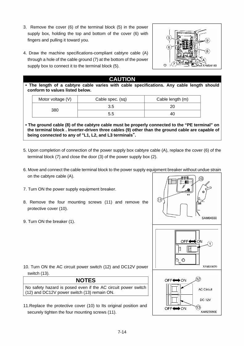
3. Remove the cover (6) of the terminal block (5) in the power
supply box, holding the top and bottom of the cover (6) with
fingers and pulling it toward you.
4. Draw the machine specifications-compliant cabtyre cable (A)
through a hole of the cable ground (7) at the bottom of the power
supply box to connect it to the terminal block (5).
CAUTION • The length of a cabtyre cable varies with cable specifications. Any cable length should conform to values listed below.
• The ground cable (8) of the cabtyre cable must be properly connected to the “PE terminal” on the terminal block . Inverter-driven three cables (9) other than the ground cable are capable of being connected to any of "L1, L2, and L3 terminals”.
Motor voltage (V) Cable spec. (sq) Cable length (m)
3.5 20 380
5.5 40
5. Upon completion of connection of the power supply box cabtyre cable (A), replace the cover (6) of the
terminal block (7) and close the door (3) of the power supply box (2).
6. Move and connect the cable terminal block to the power supply equipment breaker without undue strain
on the cabtyre cable (A).
7. Turn ON the power supply equipment breaker.
8. Remove the four mounting screws (11) and remove the
protective cover (10).
9. Turn ON the breaker (1).
10. Turn ON the AC circuit power switch (12) and DC12V power
switch (13).
NOTES
No safety hazard is posed even if the AC circuit power switch (12) and DC12V power switch (13) remain ON.
11.Replace the protective cover (10) to Its original position and
securely tighten the four mounting screws (11).
7-14
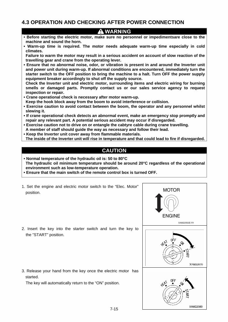
4.3 OPERATION AND CHECKING AFTER POWER CONNECTION
• Before starting the electric motor, make sure no personnel or impedimentsare close to the machine and sound the horn.
• Warm-up time is required. The motor needs adequate warm-up time especially in cold climates. Failure to warm the motor may result in a serious accident on account of slow reaction of the travelling gear and crane from the operating lever.
• Ensure that no abnormal noise, odor, or vibration is present in and around the Inverter unit and power unit during warm-up. If abnormal conditions are encountered, immediately turn the starter switch to the OFF position to bring the machine to a halt. Turn OFF the power supply equipment breaker accordingly to shut off the supply source. Check the Inverter unit and electric motor, surrounding items and electric wiring for burning smells or damaged parts. Promptly contact us or our sales service agency to request inspection or repair.
• Crane operational check is necessary after motor warm-up. Keep the hook block away from the boom to avoid interference or collision.
• Exercise caution to avoid contact between the boom, the operator and any personnel whilst slewing it.
• If crane operational check detects an abnormal event, make an emergency stop promptly and repair any relevant part. A potential serious accident may occur if disregarded.
• Exercise caution not to drive on or entangle the cabtyre cable during crane travelling. A member of staff should guide the way as necessary and follow their lead.
• Keep the Inverter unit cover away from flammable materials. The inside of the Inverter unit will rise in temperature and that could lead to fire if disregarded.
CAUTION
• Normal temperature of the hydraulic oil is: 50 to 80°C The hydraulic oil minimum temperature should be around 20°C regardless of the operational environment such as low-temperature operation.
• Ensure that the main switch of the remote control box is turned OFF.
1. Set the engine and electric motor switch to the “Elec. Motor”
position. MOTOR
ENGINEXAM22950E-R1
2. Insert the key into the starter switch and turn the key to
the ”START” position.
3. Release your hand from the key once the electric motor has
started.
The key will automatically return to the “ON” position.
7-15
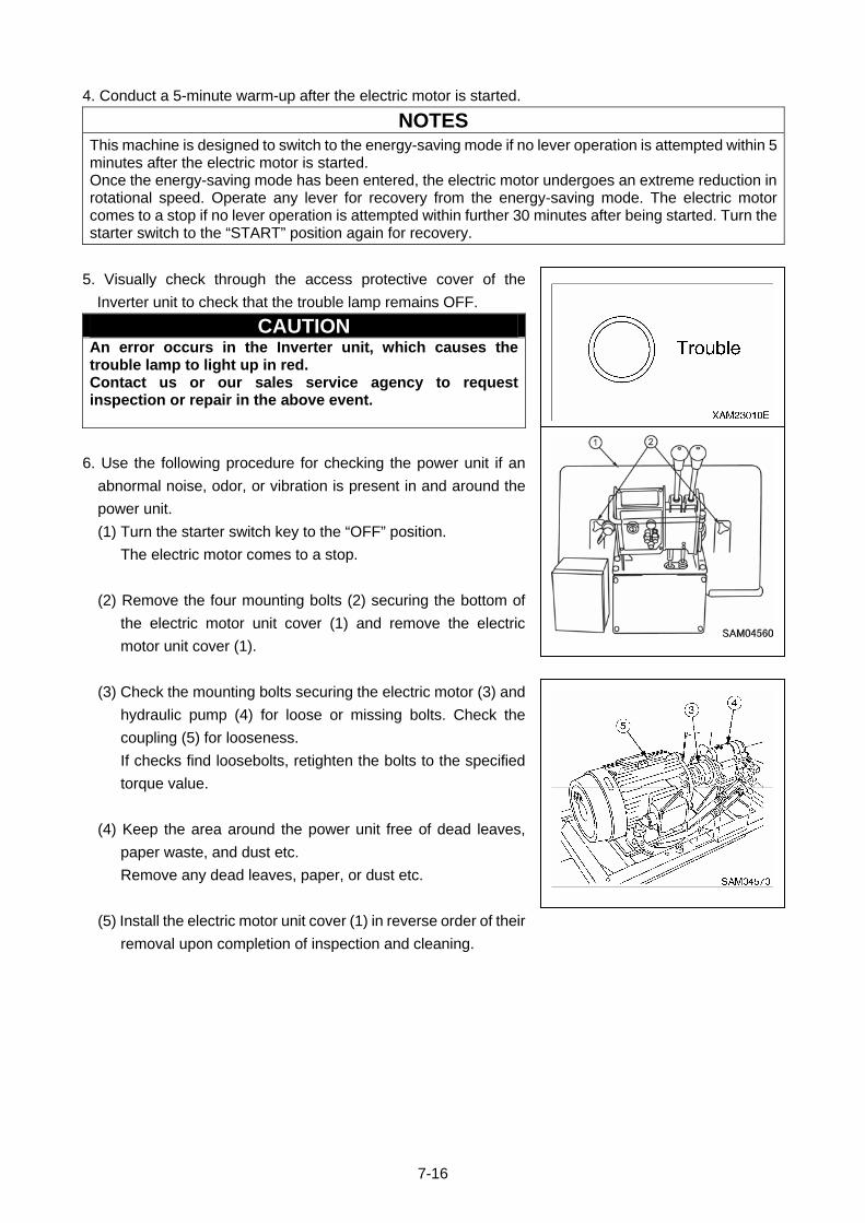
4. Conduct a 5-minute warm-up after the electric motor is started.
NOTES
This machine is designed to switch to the energy-saving mode if no lever operation is attempted within 5 minutes after the electric motor is started. Once the energy-saving mode has been entered, the electric motor undergoes an extreme reduction in rotational speed. Operate any lever for recovery from the energy-saving mode. The electric motor comes to a stop if no lever operation is attempted within further 30 minutes after being started. Turn the starter switch to the “START” position again for recovery.
5. Visually check through the access protective cover of the
Inverter unit to check that the trouble lamp remains OFF.
CAUTION An error occurs in the Inverter unit, which causes the trouble lamp to light up in red. Contact us or our sales service agency to request inspection or repair in the above event.
6. Use the following procedure for checking the power unit if an
abnormal noise, odor, or vibration is present in and around the
power unit.
(1) Turn the starter switch key to the “OFF” position.
The electric motor comes to a stop.
(2) Remove the four mounting bolts (2) securing the bottom of
the electric motor unit cover (1) and remove the electric
motor unit cover (1).
(3) Check the mounting bolts securing the electric motor (3) and
hydraulic pump (4) for loose or missing bolts. Check the
coupling (5) for looseness.
If checks find loosebolts, retighten the bolts to the specified
torque value.
(4) Keep the area around the power unit free of dead leaves,
paper waste, and dust etc.
Remove any dead leaves, paper, or dust etc.
(5) Install the electric motor unit cover (1) in reverse order of their
removal upon completion of inspection and cleaning.
7-16
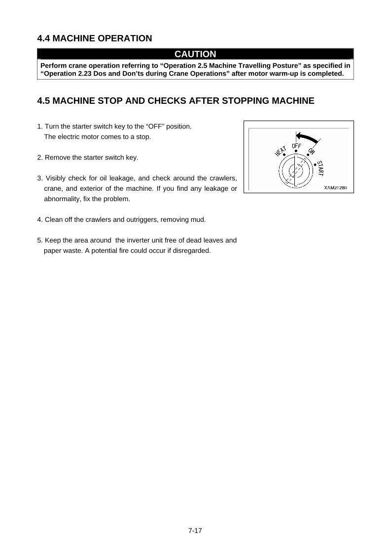
4.4 MACHINE OPERATION
CAUTION Perform crane operation referring to “Operation 2.5 Machine Travelling Posture” as specified in “Operation 2.23 Dos and Don’ts during Crane Operations” after motor warm-up is completed.
4.5 MACHINE STOP AND CHECKS AFTER STOPPING MACHINE
1. Turn the starter switch key to the “OFF” position.
The electric motor comes to a stop.
2. Remove the starter switch key.
3. Visibly check for oil leakage, and check around the crawlers,
crane, and exterior of the machine. If you find any leakage or
abnormality, fix the problem.
4. Clean off the crawlers and outriggers, removing mud.
5. Keep the area around the inverter unit free of dead leaves and
paper waste. A potential fire could occur if disregarded.
7-17
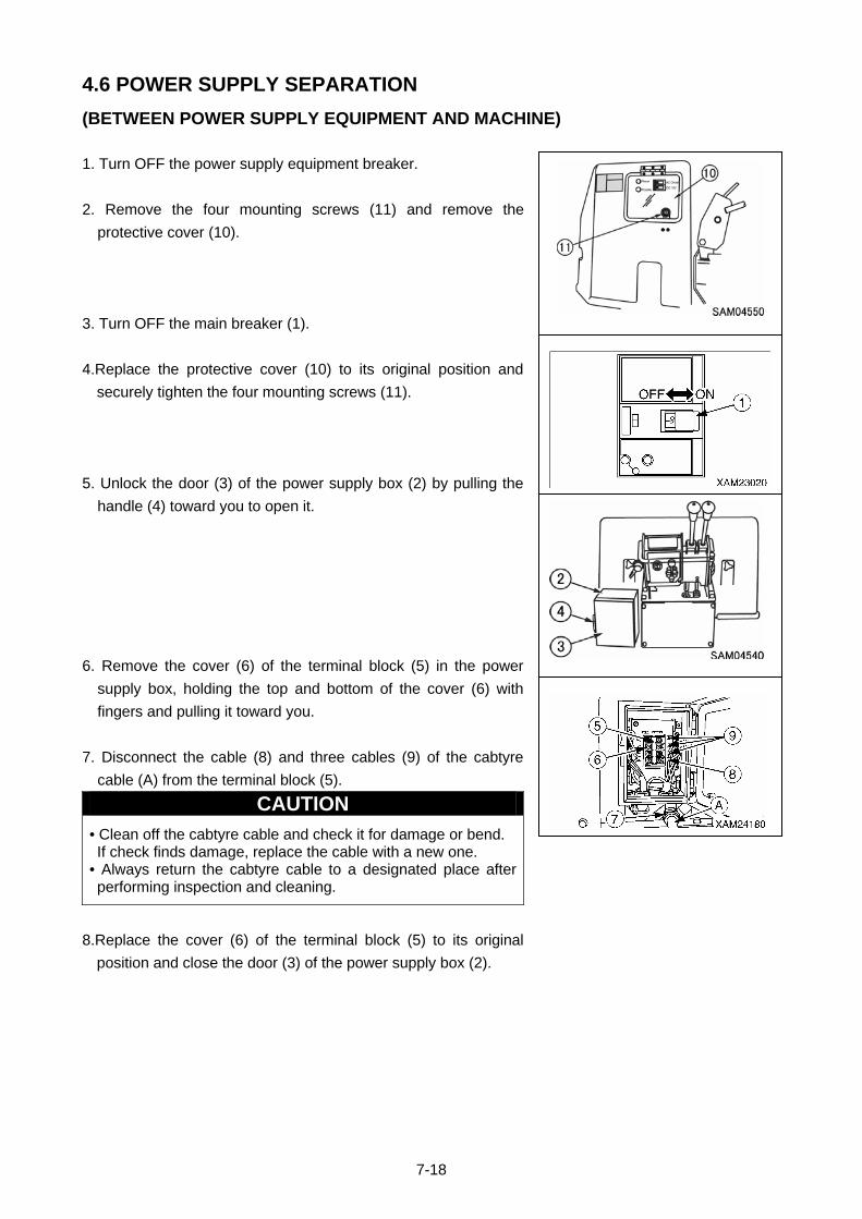
4.6 POWER SUPPLY SEPARATION
(BETWEEN POWER SUPPLY EQUIPMENT AND MACHINE)
1. Turn OFF the power supply equipment breaker.
2. Remove the four mounting screws (11) and remove the
protective cover (10).
3. Turn OFF the main breaker (1).
4.Replace the protective cover (10) to its original position and
securely tighten the four mounting screws (11).
5. Unlock the door (3) of the power supply box (2) by pulling the
handle (4) toward you to open it.
6. Remove the cover (6) of the terminal block (5) in the power
supply box, holding the top and bottom of the cover (6) with
fingers and pulling it toward you.
7. Disconnect the cable (8) and three cables (9) of the cabtyre
cable (A) from the terminal block (5).
CAUTION
• Clean off the cabtyre cable and check it for damage or bend. If check finds damage, replace the cable with a new one.
• Always return the cabtyre cable to a designated place after performing inspection and cleaning.
8.Replace the cover (6) of the terminal block (5) to its original
position and close the door (3) of the power supply box (2).
7-18

5. LONG-TERM STORAGE
CAUTION • See “Operation 7. Long-Term Storage” for long-term storage. • This section describes only the long-term storage method that is not defined in standard specifications.
Use the following procedure for storing the machine for 6 months or longer (3 months or longer if stored in
hot and humid surroundings).
• Cover the electric motor and hydraulic pump of the power unit with a plastic sheet. Keep the machine dry
with a dehumidifying agent in the covered sheet.
• Conduct 5-minute idling of engine quarterly during long-term storage.
CAUTION • Quarterly, insulation resistance test of the electric motor wiring is required during long-term storage. Contact us or our sales service agency to request inspection in the above event.
• Insulation resistance test of the electric motor wiring is required before resuming use of the machine after long-term storage. Contact us or our sales service agency to request inspection in the above event.
7-19
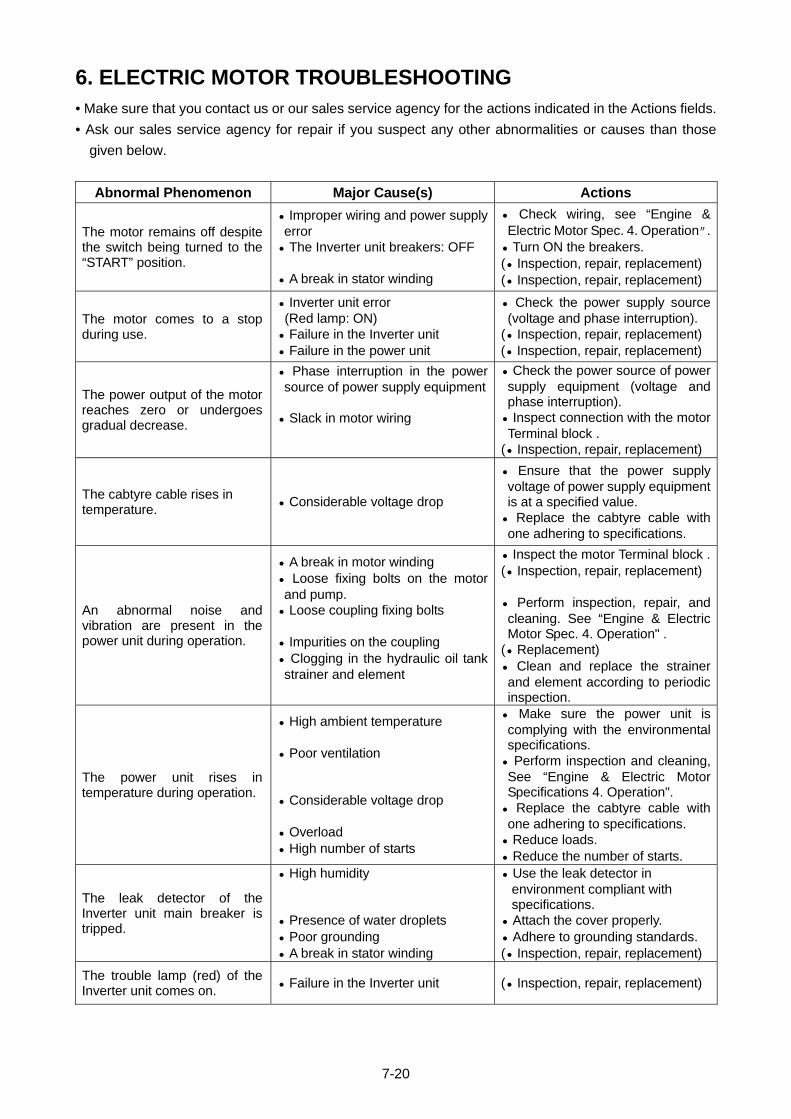
6. ELECTRIC MOTOR TROUBLESHOOTING • Make sure that you contact us or our sales service agency for the actions indicated in the Actions fields.
• Ask our sales service agency for repair if you suspect any other abnormalities or causes than those
given below.
Abnormal Phenomenon Major Cause(s) Actions
• Check wiring, see “Engine & Electric Motor Spec. 4. Operation”.
• Improper wiring and power supply error The motor remains off despite
the switch being turned to the “START” position.
• Turn ON the breakers. • The Inverter unit breakers: OFF (• Inspection, repair, replacement) • A break in stator winding (• Inspection, repair, replacement)
• Check the power supply source (voltage and phase interruption).
• Inverter unit error (Red lamp: ON) The motor comes to a stop
during use. (• Inspection, repair, replacement) • Failure in the Inverter unit • Failure in the power unit (• Inspection, repair, replacement)
The power output of the motor reaches zero or undergoes gradual decrease.
• Phase interruption in the power source of power supply equipment
• Check the power source of power supply equipment (voltage and phase interruption).
• Inspect connection with the motor Terminal block .
• Slack in motor wiring
(• Inspection, repair, replacement)
The cabtyre cable rises in temperature.
• Considerable voltage drop
• Ensure that the power supply voltage of power supply equipment is at a specified value.
• Replace the cabtyre cable with one adhering to specifications.
An abnormal noise and vibration are present in the power unit during operation.
• A break in motor winding • Loose fixing bolts on the motor and pump.
• Loose coupling fixing bolts • Impurities on the coupling • Clogging in the hydraulic oil tank strainer and element
• Inspect the motor Terminal block .(• Inspection, repair, replacement) • Perform inspection, repair, and cleaning. See “Engine & Electric Motor Spec. 4. Operation" .
(• Replacement) • Clean and replace the strainer and element according to periodic inspection.
• Make sure the power unit is complying with the environmental specifications.
The power unit rises in temperature during operation.
• High ambient temperature • Poor ventilation • Considerable voltage drop • Overload • High number of starts
• Perform inspection and cleaning, See “Engine & Electric Motor Specifications 4. Operation".
• Replace the cabtyre cable with one adhering to specifications.
• Reduce loads. • Reduce the number of starts.
The leak detector of the Inverter unit main breaker is tripped.
• High humidity • Presence of water droplets • Poor grounding • A break in stator winding
• Use the leak detector in environment compliant with specifications.
• Attach the cover properly. • Adhere to grounding standards. (• Inspection, repair, replacement)
The trouble lamp (red) of the Inverter unit comes on.
• Failure in the Inverter unit (• Inspection, repair, replacement)
7-20

7. PRINCIPLE SPECIFICATION LIST System / Item MC285C-2E (Engine and Electric Motor Specifications) Machine weight 2120kg Overall length width height
3320mm x 750mm x 1470mm
Distance between center idler and sprocket
975mm
Track gauge 550mm
Weight and dimensions
Width of crawler 200mm Crane capacity 2.82t x 1.4m Maximum working radius 8.2m Performanc
e Maximum lifting height above ground
8.7m
Type Hydraulic motor driven with brake, differential planetary gear type, with counter balance valve(within drum type)
Hook hoist speed Engine: 9.3 m/min (4 layers, 4 parts of line) Winch system
Hoist wire rope IWRC 6 x Fi (29) 7 mm x 48 m
Type Sequential hydraulic cylinders × 2 + wire rope telescoping systems × 2
Type of boom Fully automatic 5-section pentagonal telescopic
(3 to 5 stage: simultaneous telescoping) Boom length 2.535m – 4.075m – 5.575m – 7.075m – 8.575m
Telescoping system
Boom telescoping stroke/ time
Engine: 6.04 m/22 sec
Type Hydraulic double acting cylinder,direct acting type × 2 Boom hoist system Derrick angle/ time Engine: 0 to 80° /14 sec
Type Swing bearing support, hydraulic motor drive, worm and spur gears, worm self-lock
Slewing system
Slewing angle/ speed Engine: 360° (continuous)/60 sec (1.0 RPM)
Type 1st stage with flexible stay damper, 2nd stage manual pullout, hydraulic cylinder direct acting type Outrigger
system Max extended width (Front) 3810mm x (Right/left) 4580mm x (Rear) 4530mm
Type Hydraulic motor driven, Step-less speed changer
Travel speed Forward/backward: 0 – 2.2 km/h Grade ability 20°.
Travelling system
Ground pressure 53.3 kPa(0.537kgf/c㎡)
Hydraulic pump Engine: Double-throw variable piston pump Electric: Double-throw variable piston pump
Rated pressure 20.6MPa (210kgf/cm2) Hydraulic system
Hydraulic oil tank capacity 20L Model Yanmar 2TNV70-NMBA Type In-line 2-cylinder, water cooled, 4-cycle diesel Displacement 0.569L (569cc) Rated output (continuous) 7.4kW/2500min-1 (10.1PS/2500rpm)
Engine
Fuel tank capacity Diesel 12L Battery Model 55B24R (DC12V x 1 piece)
Motor specifications Three-phase induction motor: 5.5kW 4P 380V 50Hz Electric motor Starting method Inverter-controlled (30 to 60Hz)
Safety device
Over hoist detector, over un-winding detector, angle indicator, hydraulic safety valve, wire rope latch, level, machine body inclination alarm, EMO Switch, crane outrigger interlock device, moment limiter, outrigger setting light, working status light
7-21
8. SPECIFICATION DIMENSINAL DRAWING
7-22
9. DIMENSIONAL DRAWING OF OUTRIGGER WIDTH
7-23

7-24

SEARCHER HOOK
1. SAFETY DECAL LOCATIONS 8- 2
2. SEARCHER HOOK EACH SECTION 8- 4
3. NAMES OF MOMENT LIMITER DISPLAY UNIT 8- 6
4. OPERATION 8- 8
5. INSPECTION AND MAINTENANCE 8-10
6. WORKING RANGE AND RATED TOTAL LOAD 8-13
8-2
1. SAFETY DECAL LOCATIONS
8-3
① 102-4608500
② 101-4608700
③ 102-2150000
④ 102-4608000
⑤ 103-4607100
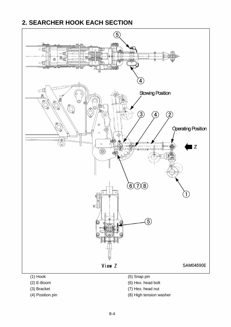
8-4
2. SEARCHER HOOK EACH SECTION
(1) Hook
(2) E-Boom
(3) Bracket
(4) Position pin
(5) Snap pin
(6) Hex. head bolt
(7) Hex. head nut
(8) High tension washer

8-5
3. MOMENT LIMITER DISPLAY UNIT
(1) Boom angle display
(2) Lifting height display
(3) Boom length display
(4) Boom lifting height upper limit LED (Orange)
(5) Boom lifting height upper limit switch
(6) Boom angle lower limit LED (Orange)
(7) Boom angle lower limit switch
(8) Load factor LED
(Changes to green, yellow, and red)
(9) Two Block LED (Red)
(10) Load capacity display (Yellow)
(11) Actual load display
(12) Rated total load display
(13) Working radius display
(14) Working radius upper limit switch
(15) Working radius upper limit LED (Red)
(16) Over un-winding LED (Red)
(17) Boom angle upper limit switch
(18) Boom angle upper limit LED (Orange)
(19) Outrigger MIN. extension LED (Blue)
(20) Outrigger MAX. extension LED (Blue)
(21) Check switch
(22) Cancel switch
(23) Fall mode selector switch
(24) 1-fall LED (Blue)
(25) 2-fall LED (Blue)
(26) 4-fall LED (Blue)
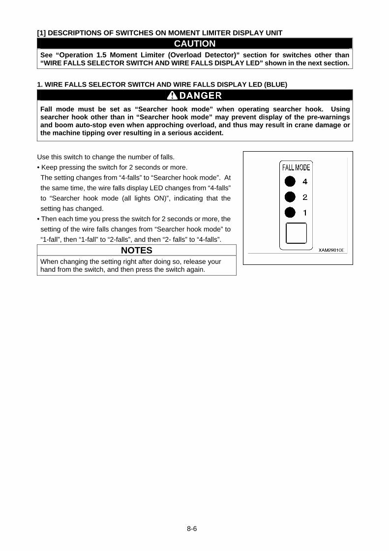
8-6
[1] DESCRIPTIONS OF SWITCHES ON MOMENT LIMITER DISPLAY UNIT
CAUTION See “Operation 1.5 Moment Limiter (Overload Detector)” section for switches other than “WIRE FALLS SELECTOR SWITCH AND WIRE FALLS DISPLAY LED” shown in the next section.
1. WIRE FALLS SELECTOR SWITCH AND WIRE FALLS DISPLAY LED (BLUE)
Fall mode must be set as “Searcher hook mode” when operating searcher hook. Using searcher hook other than in “Searcher hook mode” may prevent display of the pre-warnings and boom auto-stop even when approching overload, and thus may result in crane damage or the machine tipping over resulting in a serious accident.
Use this switch to change the number of falls.
• Keep pressing the switch for 2 seconds or more.
The setting changes from “4-falls” to “Searcher hook mode”. At
the same time, the wire falls display LED changes from “4-falls”
to “Searcher hook mode (all lights ON)”, indicating that the
setting has changed.
• Then each time you press the switch for 2 seconds or more, the
setting of the wire falls changes from “Searcher hook mode” to
“1-fall”, then “1-fall” to “2-falls”, and then “2- falls” to “4-falls”.
NOTES
When changing the setting right after doing so, release your hand from the switch, and then press the switch again.
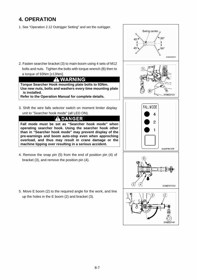
8-7
4. OPERATION 1. See “Operation 2.12 Outrigger Setting” and set the outrigger.
2. Fasten searcher bracket (3) to main-boom using 4 sets of M12
bolts and nuts. Tighten the bolts with torque wrench (B) then to
a torque of 93Nm [±13Nm].
Torque Searcher Hook mounting plate bolts to 93Nm. Use new nuts, bolts and washers every time mounting plate
is installed. Refer to the Operation Manual for complete details.
3. Shift the wire falls selector switch on moment limiter display
unit to ”Searcher hook mode” (all LED ON).
Fall mode must be set as “Searcher hook mode” when operating searcher hook. Using the searcher hook other than in “Searcher hook mode” may prevent display of the pre-warnings and boom auto-stop even when approching overload, and thus may result in crane damage or the machine tipping over resulting in a serious accident.
4. Remove the snap pin (5) from the end of position pin (4) of
bracket (3), and remove the position pin (4).
5. Move E boom (2) to the required angle for the work, and line
up the holes in the E boom (2) and bracket (3).
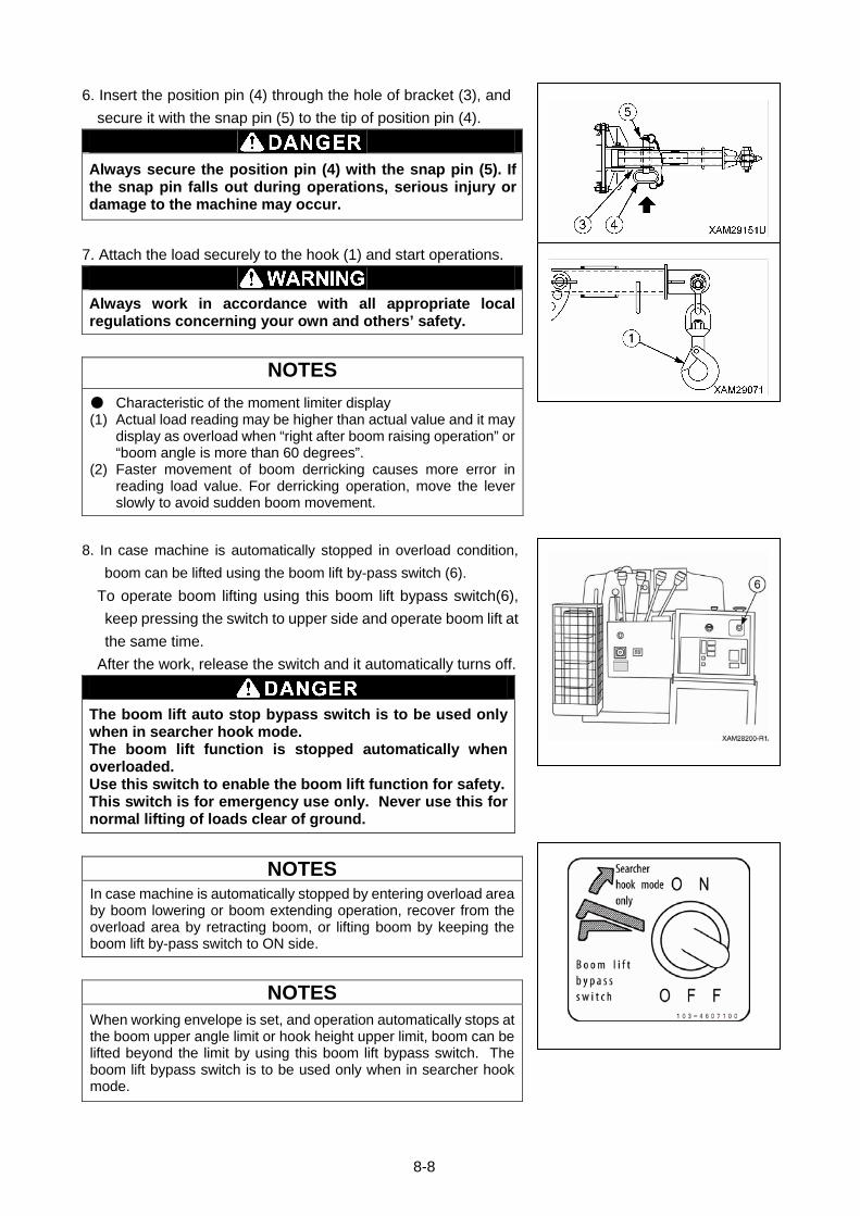
8-8
6. Insert the position pin (4) through the hole of bracket (3), and
secure it with the snap pin (5) to the tip of position pin (4).
Always secure the position pin (4) with the snap pin (5). If the snap pin falls out during operations, serious injury or damage to the machine may occur.
7. Attach the load securely to the hook (1) and start operations.
Always work in accordance with all appropriate local regulations concerning your own and others’ safety.
NOTES
● Characteristic of the moment limiter display (1) Actual load reading may be higher than actual value and it may
display as overload when “right after boom raising operation” or “boom angle is more than 60 degrees”.
(2) Faster movement of boom derricking causes more error in reading load value. For derricking operation, move the lever slowly to avoid sudden boom movement.
8. In case machine is automatically stopped in overload condition,
boom can be lifted using the boom lift by-pass switch (6).
To operate boom lifting using this boom lift bypass switch(6),
keep pressing the switch to upper side and operate boom lift at
the same time.
After the work, release the switch and it automatically turns off.
The boom lift auto stop bypass switch is to be used only when in searcher hook mode. The boom lift function is stopped automatically when overloaded. Use this switch to enable the boom lift function for safety.This switch is for emergency use only. Never use this for normal lifting of loads clear of ground.
NOTES
In case machine is automatically stopped by entering overload area by boom lowering or boom extending operation, recover from the overload area by retracting boom, or lifting boom by keeping the boom lift by-pass switch to ON side.
NOTES
When working envelope is set, and operation automatically stops at the boom upper angle limit or hook height upper limit, boom can be lifted beyond the limit by using this boom lift bypass switch. The boom lift bypass switch is to be used only when in searcher hook mode.
XAM29050 新規
8-9
5. INSPECTION AND MAINTENANCE
5.1 LEGAL INSPECTION
If a periodic safety inspection is required by the laws and regulations of your country, perform that
inspection in addition to the inspection items listed below.
1. Verify that all safety devices are operating properly.
2. Check the hoist accessories, including the hook block, for problems or damage.
3. Check the structural parts of the machine, including the frame and boom, for cracks, deformation and
damage.
4. Check for loose or missing mounting bolts and joints.
5. Verify that the boom operates properly by stopping, extending, retracting, raising, lowering and
swinging the boom.
Contact Maeda or a Maeda sales service agency to request inspection and repair service as needed.
5.2 CONSUMABLES
Parts for mounting searcher hook are consumption articles. Replace it at periodic inspection or before it
reaches abrasion limits. Replace consumption articles regularly, which shall produce economical use of
this machine. Always replace with a Maeda genuine item. Check parts catalog for correct part number
for parts request.
[CONSUMABLES LIST]
Part Replacement cycle
Searcher hook fix bolt M12x35L (4pcs) Every 6 months or when damage, crack, or squash is found
Searcher hook fix nut M12x1grade (4pcs)
Every 6 months or when damage, crack, or squash is found
Searcher hook fix washer M12x3.2t (high tension)(8pcs)
Every 6 months or when damage, crack, or squash is found
Items include a halt period. Contact Maeda or a Maeda sales service agency for part replacement
information.
5.3 INSPECTION AND MAINTENANCE LIST
This document only covers searcher hook kit. For crane body, please refer to “Inspection and
Maintenance” and follow its precautions.
Inspection and maintenance items Page
5.4.1 INSPECTION OF BEFORE OPERATION 8-10
[CHECKING BEFORE STARTING ENGINE] 8-10
[1] CHECKING BOOM AND BRACKET 8-10
[2] CHECKING SEARCHER HOOK FIX BOLTS 8-10
[3] CHECKING ELECTRICAL WIRING FOR DAMAGE 8-10
[CHECKING AFTER STARTING ENGINE] 8-11
[1] CHECKING FUNCTIONS OF BOOM 8-11
[2] CHECKING MOMENT LIMITER FOR OPERATION (SEARCHER HOOK MODE) 8-11
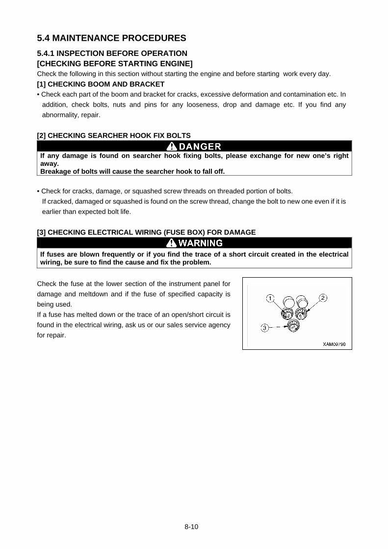
8-10
5.4 MAINTENANCE PROCEDURES
5.4.1 INSPECTION BEFORE OPERATION [CHECKING BEFORE STARTING ENGINE] Check the following in this section without starting the engine and before starting work every day.
[1] CHECKING BOOM AND BRACKET
• Check each part of the boom and bracket for cracks, excessive deformation and contamination etc. In
addition, check bolts, nuts and pins for any looseness, drop and damage etc. If you find any
abnormality, repair.
[2] CHECKING SEARCHER HOOK FIX BOLTS
If any damage is found on searcher hook fixing bolts, please exchange for new one’s right away. Breakage of bolts will cause the searcher hook to fall off.
• Check for cracks, damage, or squashed screw threads on threaded portion of bolts.
If cracked, damaged or squashed is found on the screw thread, change the bolt to new one even if it is
earlier than expected bolt life.
[3] CHECKING ELECTRICAL WIRING (FUSE BOX) FOR DAMAGE
If fuses are blown frequently or if you find the trace of a short circuit created in the electrical wiring, be sure to find the cause and fix the problem.
Check the fuse at the lower section of the instrument panel for
damage and meltdown and if the fuse of specified capacity is
being used.
If a fuse has melted down or the trace of an open/short circuit is
found in the electrical wiring, ask us or our sales service agency
for repair.
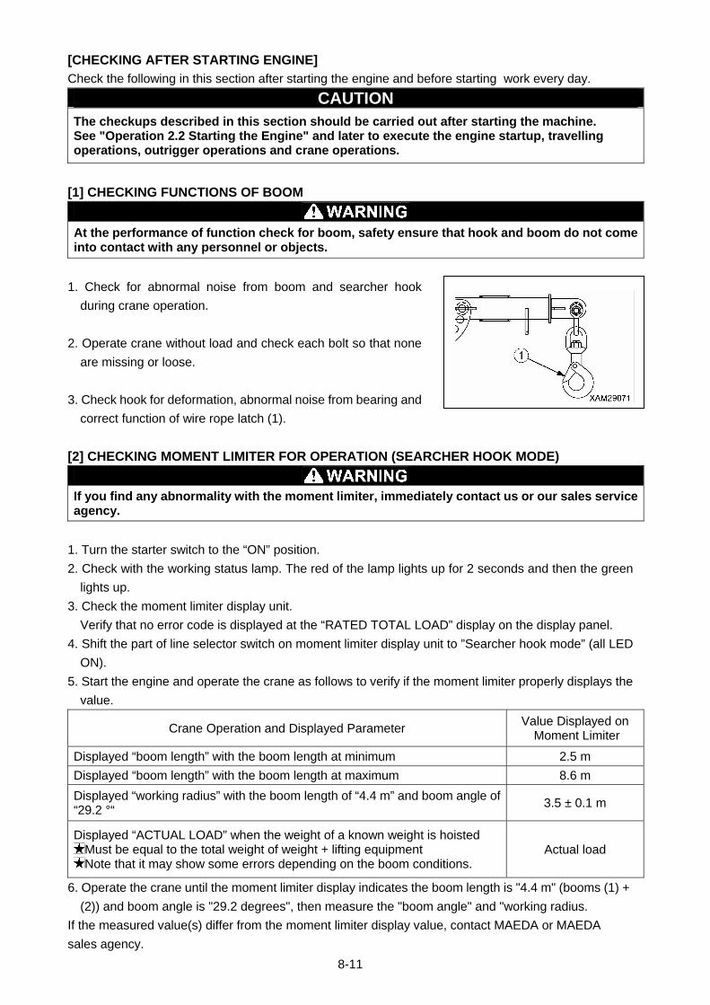
8-11
[CHECKING AFTER STARTING ENGINE]
Check the following in this section after starting the engine and before starting work every day.
CAUTION The checkups described in this section should be carried out after starting the machine. See "Operation 2.2 Starting the Engine" and later to execute the engine startup, travelling operations, outrigger operations and crane operations.
[1] CHECKING FUNCTIONS OF BOOM
At the performance of function check for boom, safety ensure that hook and boom do not come into contact with any personnel or objects.
1. Check for abnormal noise from boom and searcher hook
during crane operation.
2. Operate crane without load and check each bolt so that none
are missing or loose.
3. Check hook for deformation, abnormal noise from bearing and
correct function of wire rope latch (1).
[2] CHECKING MOMENT LIMITER FOR OPERATION (SEARCHER HOOK MODE)
If you find any abnormality with the moment limiter, immediately contact us or our sales service agency.
1. Turn the starter switch to the “ON” position.
2. Check with the working status lamp. The red of the lamp lights up for 2 seconds and then the green
lights up.
3. Check the moment limiter display unit.
Verify that no error code is displayed at the “RATED TOTAL LOAD” display on the display panel.
4. Shift the part of line selector switch on moment limiter display unit to ”Searcher hook mode” (all LED
ON).
5. Start the engine and operate the crane as follows to verify if the moment limiter properly displays the
value.
Crane Operation and Displayed Parameter Value Displayed on
Moment Limiter
Displayed “boom length” with the boom length at minimum 2.5 m
Displayed “boom length” with the boom length at maximum 8.6 m
Displayed “working radius” with the boom length of “4.4 m” and boom angle of “29.2 °“
3.5 ± 0.1 m
Displayed “ACTUAL LOAD” when the weight of a known weight is hoisted Must be equal to the total weight of weight + lifting equipment Note that it may show some errors depending on the boom conditions.
Actual load
6. Operate the crane until the moment limiter display indicates the boom length is "4.4 m" (booms (1) +
(2)) and boom angle is "29.2 degrees", then measure the "boom angle" and "working radius.
If the measured value(s) differ from the moment limiter display value, contact MAEDA or MAEDA
sales agency.
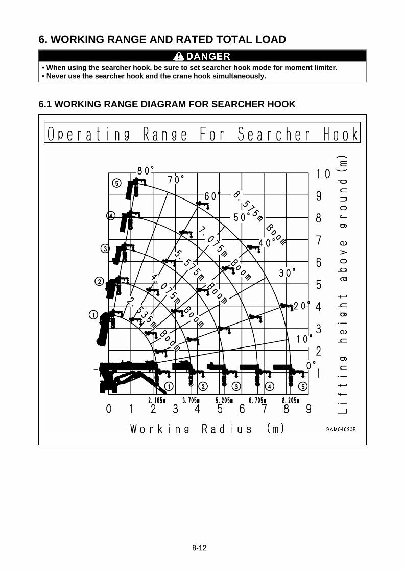
8-12
6. WORKING RANGE AND RATED TOTAL LOAD
• When using the searcher hook, be sure to set searcher hook mode for moment limiter. • Never use the searcher hook and the crane hook simultaneously.
6.1 WORKING RANGE DIAGRAM FOR SEARCHER HOOK
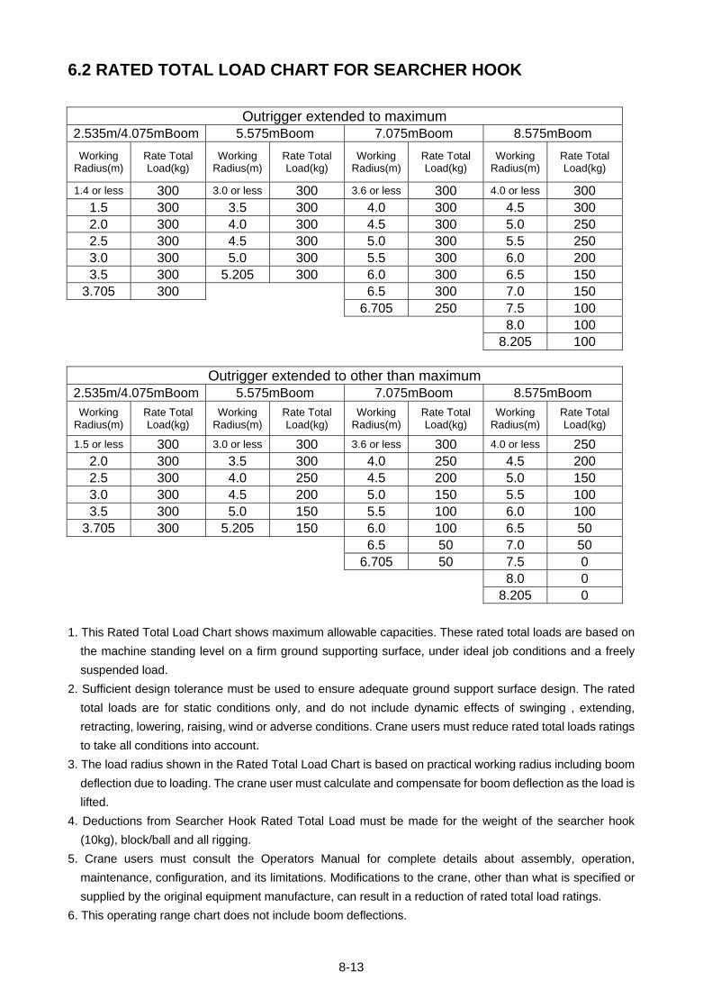
8-13
6.2 RATED TOTAL LOAD CHART FOR SEARCHER HOOK
Outrigger extended to maximum 2.535m/4.075mBoom 5.575mBoom 7.075mBoom 8.575mBoom
Working Radius(m)
Rate Total Load(kg)
Working Radius(m)
Rate Total Load(kg)
Working Radius(m)
Rate Total Load(kg)
Working Radius(m)
Rate Total Load(kg)
1.4 or less 300 3.0 or less 300 3.6 or less 300 4.0 or less 300 1.5 300 3.5 300 4.0 300 4.5 300 2.0 300 4.0 300 4.5 300 5.0 250 2.5 300 4.5 300 5.0 300 5.5 250 3.0 300 5.0 300 5.5 300 6.0 200 3.5 300 5.205 300 6.0 300 6.5 150
3.705 300 6.5 300 7.0 150 6.705 250 7.5 100 8.0 100 8.205 100
Outrigger extended to other than maximum 2.535m/4.075mBoom 5.575mBoom 7.075mBoom 8.575mBoom
Working Radius(m)
Rate Total Load(kg)
Working Radius(m)
Rate Total Load(kg)
Working Radius(m)
Rate Total Load(kg)
Working Radius(m)
Rate Total Load(kg)
1.5 or less 300 3.0 or less 300 3.6 or less 300 4.0 or less 250 2.0 300 3.5 300 4.0 250 4.5 200 2.5 300 4.0 250 4.5 200 5.0 150 3.0 300 4.5 200 5.0 150 5.5 100 3.5 300 5.0 150 5.5 100 6.0 100
3.705 300 5.205 150 6.0 100 6.5 50 6.5 50 7.0 50 6.705 50 7.5 0 8.0 0 8.205 0
1. This Rated Total Load Chart shows maximum allowable capacities. These rated total loads are based on
the machine standing level on a firm ground supporting surface, under ideal job conditions and a freely
suspended load.
2. Sufficient design tolerance must be used to ensure adequate ground support surface design. The rated
total loads are for static conditions only, and do not include dynamic effects of swinging , extending,
retracting, lowering, raising, wind or adverse conditions. Crane users must reduce rated total loads ratings
to take all conditions into account.
3. The load radius shown in the Rated Total Load Chart is based on practical working radius including boom
deflection due to loading. The crane user must calculate and compensate for boom deflection as the load is
lifted.
4. Deductions from Searcher Hook Rated Total Load must be made for the weight of the searcher hook
(10kg), block/ball and all rigging.
5. Crane users must consult the Operators Manual for complete details about assembly, operation,
maintenance, configuration, and its limitations. Modifications to the crane, other than what is specified or
supplied by the original equipment manufacture, can result in a reduction of rated total load ratings.
6. This operating range chart does not include boom deflections.

MAEDA MINI-CRAWLER CRANE MC285C-2 OPERATION MANUAL
Document No: 102E-OM1109-01
Second edition: September 22, 2011
Issued by Maeda Seisakusho Co., Ltd.
1095 Onbegawa, Shinonoi
Nagano, Nagano 388-8522,
Japan
http://www.maesei.co.jp/english/info/index.html
No part of this manual can be reproduced in any from without permission