Embed Size (px)
Citation preview

Patented Technology
PLASMA CUTTING SYSTEM
102CUTMASTER™
Rev. AC Date: April 25, 2012 Manual # 0-5012Operating Features:
Operating Manual

Patented Technology
WE APPRECIATE YOUR BUSINESS!Congratulations on your new Radnor/Thermal Dynamics product. We are proud to have you as our customer and will strive to provide you with the best service and reliability in the industry. This product is backed by our extensive warranty and world-wide service network. To locate your nearest distributor or service agency call 1-800-426-1888, or visit us on the web at www.thermal-dynamics.com.
This Operating Manual has been designed to instruct you on the correct use and operation of your Radnor/Thermal Dynamics product. Your satisfaction with this product and its safe operation is our ultimate concern. Therefore please take the time to read the entire manual, especially the Safety Precautions. They will help you to avoid potential hazards that may exist when working with this product.
YOU ARE IN GOOD COMPANY!The Brand of Choice for Contractors and Fabricators Worldwide.Thermal Dynamics is a Global Brand of manual and automation Plasma Cutting Products for Thermadyne Industries Inc.
We distinguish ourselves from our competition through market-leading, dependable products that have stood the test of time. We pride ourselves on technical innovation, competitive prices, excellent delivery, superior customer service and technical support, together with excellence in sales and marketing expertise.
Above all, we are committed to developing technologically advanced products to achieve a safer working environment within the plasma and welding industry.
! WARNINGS
Read and understand this entire Manual and your employer’s safety practices before installing, operat-ing, or servicing the equipment.
While the information contained in this Manual represents the Manufacturer's best judgement, the Manufacturer assumes no liability for its use.
Plasma Cutting Power SupplyCutMaster™ 102MC100 1Torch™Operating Manual Number 0-5012
Published by:Thermal Dynamics Corporation82 Benning StreetWest Lebanon, New Hampshire, USA 03784(603) 298-5711
www.thermal-dynamics.com
Copyright 2008, 2012 byThermadyne Corporation
All rights reserved.
Reproduction of this work, in whole or in part, without written permission of the publisher is prohibited.
The publisher does not assume and hereby disclaims any liability to any party for any loss or damage caused by any error or omission in this Manual, whether such error results from negligence, accident, or any other cause.
Original Publication Date: July 21, 2008Revision Date: April 25, 2012
Record the following information for Warranty purposes:
Where Purchased:_______________________________ ________________
Purchase Date:__________________________________ ________________
Power Supply Serial #:___________________________ ________________
Torch Serial #:___________________________________ ________________
i
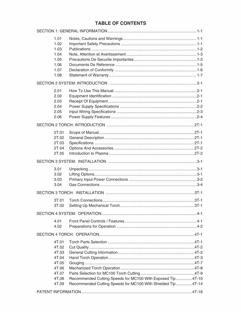
TABLE OF CONTENTS
SECTION 1: GENERAL INFORMATION .................................................................................1-1
1.01 Notes, Cautions and Warnings ...................................................................1-11.02 Important Safety Precautions .....................................................................1-11.03 Publications ................................................................................................1-21.04 Note, Attention et Avertissement ................................................................1-31.05 Precautions De Securite Importantes .........................................................1-31.06 Documents De Reference ..........................................................................1-51.07 Declaration of Conformity ...........................................................................1-61.08 Statement of Warranty ................................................................................1-7
SECTION 2 SYSTEM: INTRODUCTION ................................................................................2-1
2.01 How To Use This Manual ...........................................................................2-12.02 Equipment Identification .............................................................................2-12.03 Receipt Of Equipment .................................................................................2-12.04 Power Supply Specifications ......................................................................2-22.05 Input Wiring Specifications .........................................................................2-32.06 Power Supply Features ..............................................................................2-4
SECTION 2 TORCH: INTRODUCTION ................................................................................2T-1
2T.01 Scope of Manual .......................................................................................2T-12T.02 General Description ..................................................................................2T-12T.03 Specifications ...........................................................................................2T-12T.04 Options And Accessories ..........................................................................2T-22T.05 Introduction to Plasma ..............................................................................2T-2
SECTION 3 SYSTEM: INSTALLATION .................................................................................3-1
3.01 Unpacking ...................................................................................................3-13.02 Lifting Options .............................................................................................3-13.03 Primary Input Power Connections ..............................................................3-23.04 Gas Connections ........................................................................................3-4
SECTION 3 TORCH: INSTALLATION .................................................................................3T-1
3T.01 Torch Connections ....................................................................................3T-13T.02 Setting Up Mechanical Torch ....................................................................3T-1
SECTION 4 SYSTEM: OPERATION .......................................................................................4-1
4.01 Front Panel Controls / Features ..................................................................4-14.02 Preparations for Operation .........................................................................4-2
SECTION 4 TORCH: OPERATION .......................................................................................4T-1
4T.01 Torch Parts Selection ...............................................................................4T-14T.02 Cut Quality ................................................................................................4T-24T.03 General Cutting Information ......................................................................4T-24T.04 Hand Torch Operation ..............................................................................4T-34T.05 Gouging ....................................................................................................4T-74T.06 Mechanized Torch Operation ...................................................................4T-84T.07 Parts Selection for MC100 Torch Cutting .................................................4T-94T.08 Recommended Cutting Speeds for MC100 With Exposed Tip ...............4T-104T.09 Recommended Cutting Speeds for MC100 With Shielded Tip ...............4T-14
PATENT INFORMATION .....................................................................................................4T-18

TABLE OF CONTENTSSECTION 5 SYSTEM: SERVICE .............................................................................................5-1
5.01 General Maintenance .................................................................................5-15.02 Maintenance Schedule ...............................................................................5-25.03 Common Faults ..........................................................................................5-25.04 Fault Indicator .............................................................................................5-35.05 Basic Troubleshooting Guide ......................................................................5-45.06 Power Supply Basic Parts Replacement ....................................................5-6
SECTION 5 TORCH: SERVICE .............................................................................................5T-1
5T.01 General Maintenance ...............................................................................5T-15T.02 Inspection and Replacement of Consumable Torch Parts .......................5T-2
SECTION 6: PARTS LISTS......................................................................................................6-1
6.01 Introduction .................................................................................................6-16.02 Ordering Information ...................................................................................6-16.03 Power Supply Replacement .......................................................................6-16.04 Replacement Power Supply Parts ..............................................................6-26.05 Options and Accessories ............................................................................6-26.06 Replacement Parts for Hand Torch ...........................................................6-36.07 Replacement Parts - for Machine Torches with Unshielded Leads ............6-46.08 Torch Consumable Parts (MC100) .............................................................6-6
APPENDIX 1: SEQUENCE OF OPERATION (BLOCK DIAGRAM) ....................................... A-1
APPENDIX 2: DATA TAG INFORMATION ............................................................................ A-2
APPENDIX 3: TORCH PIN - OUT DIAGRAMS ...................................................................... A-3
APPENDIX 4: TORCH CONNECTION DIAGRAMS .............................................................. A-4
APPENDIX 5: SYSTEM SCHEMATIC, 208/460V UNITS ...................................................... A-6
APPENDIX 6: Publication History........................................................................................... A-8
GLOBAL CUSTOMER SERVICE CONTACT INFORMATION ........................ Inside Rear Cover

This Page Intentionally Blank
CUTMASTER 102
Manual 0-5012 1-1 GENERAL INFORMATION
SECTION 1: GENERAL INFORMATION
1.01 Notes, Cautions and Warnings
Throughout this manual, notes, cautions, and warnings are used to highlight important information. These highlights are categorized as follows:
NOTE
An operation, procedure, or background information which requires additional emphasis or is helpful in ef-ficient operation of the system.
CAUTION
A procedure which, if not properly followed, may cause damage to the equipment.
!WARNING
A procedure which, if not properly followed, may cause injury to the operator or others in the operating area.
1.02 Important Safety Precautions
WARNINGS
OPERATION AND MAINTENANCE OF PLASMA ARC EQUIPMENT CAN BE DANGEROUS AND HAZARDOUS TO YOUR HEALTH.
Plasma arc cutting produces intense electric and magnetic emissions that may interfere with the proper function of cardiac pacemakers, hearing aids, or other electronic health equipment. Persons who work near plasma arc cutting applications should consult their medical health professional and the manufacturer of the health equipment to determine whether a hazard exists.
To prevent possible injury, read, understand and follow all warnings, safety precautions and instructions before using the equipment. Call 1-603-298-5711 or your local distributor if you have any questions.
GASES AND FUMES
Gases and fumes produced during the plasma cutting process can be dangerous and hazardous to your health.
• Keepallfumesandgasesfromthebreathingarea.Keepyourhead out of the welding fume plume.
• Useanair-suppliedrespiratorifventilationisnotadequatetoremove all fumes and gases.
• Thekindsoffumesandgasesfromtheplasmaarcdependonthe kind of metal being used, coatings on the metal, and the different processes. You must be very careful when cutting or welding any metals which may contain one or more of the following:
Antimony Chromium Mercury Arsenic Cobalt Nickel Barium Copper Selenium Beryllium Lead Silver Cadmium Manganese Vanadium
• AlwaysreadtheMaterialSafetyDataSheets(MSDS)thatshouldbe supplied with the material you are using. These MSDSs will give you the information regarding the kind and amount of fumes and gases that may be dangerous to your health.
• For informationonhowtotestforfumesandgases inyourworkplace, refer to item 1 in Subsection 1.03, Publications in this manual.
• Usespecialequipment,suchaswaterordowndraftcuttingtables, to capture fumes and gases.
• Donotusetheplasmatorchinanareawherecombustibleorexplosive gases or materials are located.
• Phosgene,atoxicgas,isgeneratedfromthevaporsofchlo-rinated solvents and cleansers. Remove all sources of these vapors.
• This product,when used forwelding or cutting, producesfumes or gases which contain chemicals known to the State of California to cause birth defects and, in some cases, cancer. (CaliforniaHealth&SafetyCodeSec.25249.5etseq.)
ELECTRIC SHOCK
Electric Shock can injure or kill. The plasma arc process uses and produces high voltage electrical energy. This electric energy can cause severe or fatal shock to the operator or others in the workplace.
• Nevertouchanypartsthatareelectrically“live”or“hot.”
• Weardryglovesandclothing.Insulateyourselffromtheworkpiece or other parts of the welding circuit.
• Repairorreplaceallwornordamagedparts.
• Extra caremust be takenwhen theworkplace ismoist ordamp.
• InstallandmaintainequipmentaccordingtoNECcode,refertoitem9inSubsection1.03,Publications.
• Disconnect power source before performing any service orrepairs.
• ReadandfollowalltheinstructionsintheOperatingManual.
FIRE AND EXPLOSION
Fireandexplosioncanbecausedbyhotslag,sparks,ortheplasmaarc.
• Besurethereisnocombustibleorflammablematerialintheworkplace. Any material that cannot be removed must be protected.
• Ventilate all flammable or explosive vapors from thework-place.
CUTMASTER 102
GENERAL INFORMATION 1-2 Manual 0-5012
• Donotcutorweldoncontainersthatmayhaveheldcombus-tibles.
• Provideafirewatchwhenworkinginanareawherefirehazardsmay exist.
• Hydrogengasmaybe formedand trappedunderaluminumworkpieces when they are cut underwater or while using a water table. DO NOT cut aluminum alloys underwater or on a water table unless the hydrogen gas can be eliminated or dissipated. Trapped hydrogen gas that is ignited will cause an explosion.
NOISE
Noise can cause permanent hearing loss. Plasma arc processes can cause noise levels to exceed safe limits. You must protect your ears from loud noise to prevent permanent loss of hearing.
• Toprotectyourhearingfromloudnoise,wearprotectiveearplugs and/or ear muffs. Protect others in the workplace.
• Noiselevelsshouldbemeasuredtobesurethedecibels(sound)do not exceed safe levels.
• Forinformationonhowtotestfornoise,seeitem1inSubsec-tion 1.03, Publications, in this manual.
PLASMA ARC RAYS
Plasma Arc Rays can injure your eyes and burn your skin. The plasma arc process produces very bright ultra violet and infra red light. These arc rays will damage your eyes and burn your skin if you are not properly protected.
• Toprotectyoureyes,alwayswearaweldinghelmetorshield.Also always wear safety glasses with side shields, goggles or other protective eye wear.
• Wearweldingglovesandsuitableclothingtoprotectyourskinfrom the arc rays and sparks.
• Keephelmetandsafetyglasses ingoodcondition. Replacelenses when cracked, chipped or dirty.
• Protectothersintheworkareafromthearcrays.Useprotectivebooths, screens or shields.
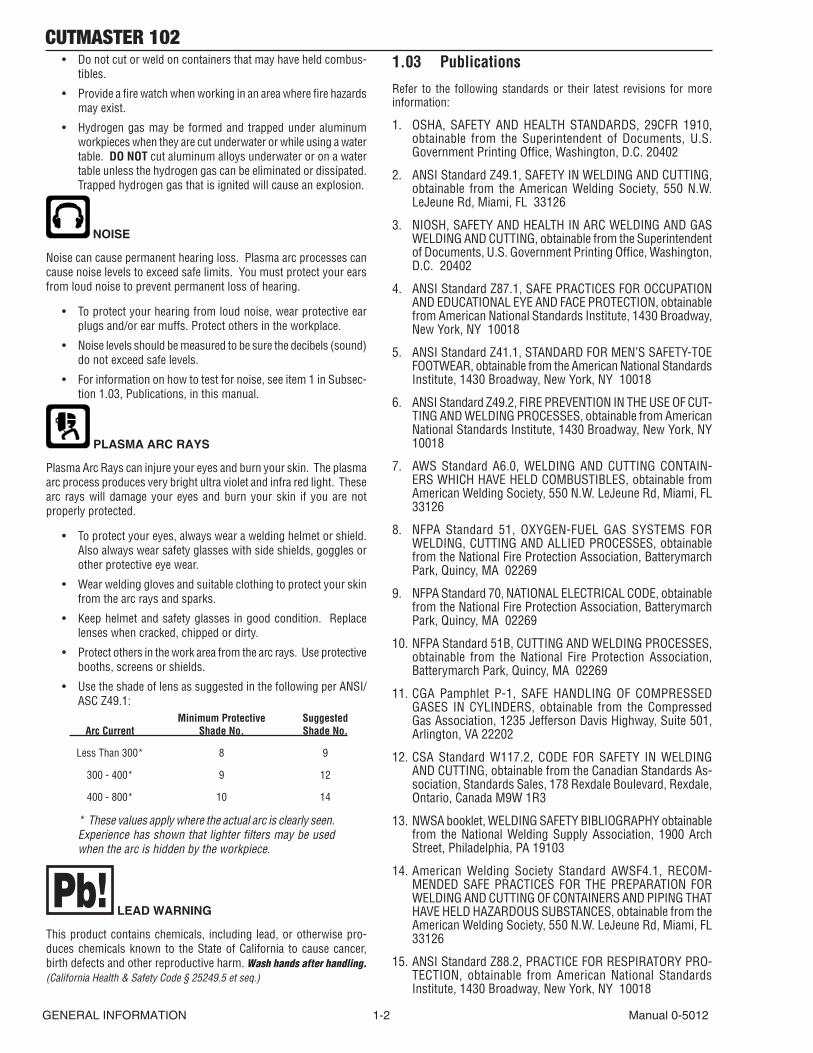
• UsetheshadeoflensassuggestedinthefollowingperANSI/ASCZ49.1:
Minimum Protective Suggested Arc Current Shade No. Shade No.
LessThan300* 8 9
300-400* 9 12
400 - 800* 10 14
* These values apply where the actual arc is clearly seen. Experience has shown that lighter filters may be used when the arc is hidden by the workpiece.
LEAD WARNING
This product contains chemicals, including lead, or otherwise pro-duces chemicals known to the State of California to cause cancer, birth defects and other reproductive harm. Wash hands after handling. (California Health & Safety Code § 25249.5 et seq.)
1.03 Publications
Refer to the following standards or their latest revisions for more information:
1. OSHA, SAFETY AND HEALTH STANDARDS, 29CFR 1910, obtainable from the Superintendent of Documents, U.S.GovernmentPrintingOffice,Washington,D.C.20402
2. ANSIStandardZ49.1,SAFETYINWELDINGANDCUTTING,obtainable from the American Welding Society, 550 N.W. LeJeuneRd,Miami,FL33126
3. NIOSH,SAFETYANDHEALTHINARCWELDINGANDGASWELDINGANDCUTTING,obtainablefromtheSuperintendentofDocuments,U.S.GovernmentPrintingOffice,Washington,D.C. 20402
4. ANSIStandardZ87.1,SAFEPRACTICESFOROCCUPATIONANDEDUCATIONALEYEANDFACEPROTECTION,obtainablefrom American National Standards Institute, 1430 Broadway, New York, NY 10018
5. ANSIStandardZ41.1,STANDARDFORMEN’SSAFETY-TOEFOOTWEAR,obtainablefromtheAmericanNationalStandardsInstitute, 1430 Broadway, New York, NY 10018
6. ANSIStandardZ49.2,FIRE PREVENTION IN THE USE OF CUT-TING AND WELDING PROCESSES, obtainable from American National Standards Institute, 1430 Broadway, New York, NY 10018
7. AWS Standard A6.0, WELDING AND CUTTING CONTAIN-ERS WHICH HAVE HELD COMBUSTIBLES, obtainable from AmericanWeldingSociety,550N.W.LeJeuneRd,Miami,FL33126
8. NFPA Standard 51, OXYGEN-FUELGAS SYSTEMS FORWELDING,CUTTINGANDALLIEDPROCESSES, obtainable fromtheNationalFireProtectionAssociation,BatterymarchPark,Quincy,MA02269
9. NFPAStandard70,NATIONALELECTRICALCODE,obtainablefromtheNationalFireProtectionAssociation,BatterymarchPark,Quincy,MA02269
10.NFPAStandard51B,CUTTINGANDWELDINGPROCESSES,obtainable from theNational Fire ProtectionAssociation,BatterymarchPark,Quincy,MA02269
11.CGA Pamphlet P-1, SAFEHANDLINGOF COMPRESSEDGASES IN CYLINDERS, obtainable from the Compressed GasAssociation,1235JeffersonDavisHighway,Suite501,Arlington, VA 22202
12.CSAStandardW117.2, CODE FORSAFETY INWELDINGANDCUTTING,obtainablefromtheCanadianStandardsAs-sociation, Standards Sales, 178 Rexdale Boulevard, Rexdale, Ontario,CanadaM9W1R3
13.NWSAbooklet,WELDINGSAFETYBIBLIOGRAPHYobtainablefrom theNationalWeldingSupplyAssociation, 1900ArchStreet,Philadelphia,PA19103
14.AmericanWelding Society Standard AWSF4.1, RECOM-MENDEDSAFEPRACTICES FORTHEPREPARATIONFORWELDINGANDCUTTINGOFCONTAINERSANDPIPINGTHATHAVEHELDHAZARDOUSSUBSTANCES,obtainablefromtheAmericanWeldingSociety,550N.W.LeJeuneRd,Miami,FL33126
15.ANSIStandardZ88.2,PRACTICEFORRESPIRATORYPRO-TECTION, obtainable from American National Standards Institute, 1430 Broadway, New York, NY 10018
CUTMASTER 102
Manual 0-5012 1-3 GENERAL INFORMATION
1.04 Note, Attention et Avertissement
Danscemanuel,lesmots“note,”“attention,”et“avertissement”sontutilisés pour mettre en relief des informations à caractère important. Cesmisesenreliefsontclassifiéescommesuit:
NOTE
Toute opération, procédure ou renseignement général sur lequel il importe d’insister davantage ou qui contribue à l’efficacité de fonctionnement du système.
ATTENTION
Toute procédure pouvant résulter l’endommagement du matériel en cas de non-respect de la procédure en question.
!AVERTISSEMENT
Toute procédure pouvant provoquer des blessures de l’opérateur ou des autres personnes se trouvant dans la zone de travail en cas de non-respect de la procédure en question.
1.05 Precautions De Securite Importantes
AVERTISSEMENTS
L’OPÉRATION ET LA MAINTENANCE DU MATÉRIEL DE SOUDAGE À L’ARC AU JET DE PLASMA PEUVENT PRÉ-SENTER DES RISQUES ET DES DANGERS DE SANTÉ.
Coupant à l’arc au jet de plasma produit de l’énergie électrique haute tension et des émissions magnétique qui peuvent interférer la fonction propre d’un “pacemaker” cardiaque, les appareils auditif, ou autre matériel de santé electronique. Ceux qui travail près d’une application à l’arc au jet de plasma devrait consulter leur membre pro-fessionel de médication et le manufacturier de matériel de santé pour déterminer s’il existe des risques de santé.
Il faut communiquer aux opérateurs et au personnel TOUS les dangers possibles. Afin d’éviter les blessures possibles, lisez, comprenez et suivez tous les avertis-sements, toutes les précautions de sécurité et toutes les consignes avant d’utiliser le matériel. Composez le + 603-298-5711 ou votre distributeur local si vous avez des questions.
FUMÉE et GAZ
La fumée et les gaz produits par le procédé de jet de plasma peuvent présenterdesrisquesetdesdangersdesanté.
• Eloigneztoutefuméeetgazdevotrezonederespiration.Gardezvotre tête hors de la plume de fumée provenant du chalumeau.
• Utilisezunappareilrespiratoireàalimentationenairsil’aérationfournienepermetpasd’éliminerlafuméeetlesgaz.
• Lessortesdegazetdefuméeprovenantdel’arcdeplasmadépen-dent du genre de métal utilisé, des revêtements se trouvant sur le métaletdesdifférentsprocédés.Vousdevezprendresoinlorsquevous coupez ou soudez tout métal pouvant contenir un ou plusieurs des éléments suivants:
antimoine cadmium mercure argent chrome nickel arsenic cobalt plomb baryum cuivre sélénium béryllium manganèse vanadium
• Liseztoujourslesfichesdedonnéessurlasécuritédesmatières(sigleaméricain“MSDS”);celles-cidevraientêtre fourniesaveclematérielquevousutilisez.LesMSDScontiennentdesrensei-gnementsquantàlaquantitéetlanaturedelafuméeetdesgazpouvant poser des dangers de santé.
• Pourdesinformationssurlamanièredetesterlafuméeetlesgazdevotrelieudetravail,consultezl’article1etlesdocumentscitésà la page 5.
• Utilisezunéquipementspécialtelquedestablesdecoupeàdébitd’eauouàcourantdescendantpourcapterlafuméeetlesgaz.
• N’utilisezpaslechalumeauaujetdeplasmadansunezoneoùsetrouvent des matières ou des gaz combustibles ou explosifs.
• Lephosgène,ungaztoxique,estgénéréparlafuméeprovenantdes solvants et des produits de nettoyage chlorés. Eliminez toute source de telle fumée.
• Ceproduit,dansleprocéderdesoudageetdecoupe,produitdela fumée ou des gaz pouvant contenir des éléments reconnu dans L’étatdelaCalifornie,quipeuventcauserdesdéfautsdenaissanceetlecancer.(LasécuritédesantéenCalifornieetlacodesécuritéSec.25249.5etseq.)
CHOC ELECTRIQUE
Leschocsélectriquespeuventblesseroumêmetuer.Leprocédéaujetdeplasmarequiertetproduitdel’énergieélectriquehautetension.Cetteénergieélectriquepeutproduiredeschocsgraves,voiremortels,pourl’opérateuretlesautrespersonnessurlelieudetravail.
• Netouchezjamaisunepièce“soustension”ou“vive”;portezdesgants et des vêtements secs. Isolez-vous de la pièce de travail ou des autres parties du circuit de soudage.
• Réparezouremplaceztoutepièceuséeouendommagée.
• Prenezdessoinsparticulierslorsquelazonedetravailesthumideou moite.
• MontezetmaintenezlematérielconformémentauCodeélectriquenationaldesEtats-Unis.(Voirlapage5, article9.)
• Débranchezl’alimentationélectriqueavanttouttravaild’entretienou de réparation.
• LisezetrespecteztouteslesconsignesduManueldeconsignes.
INCENDIE ET EXPLOSION
Les incendies et les explosions peuvent résulter des scories chaudes, desétincellesoude l’arcdeplasma. Leprocédéà l’arcdeplasma

CUTMASTER 102
GENERAL INFORMATION 1-4 Manual 0-5012
produit du métal, des étincelles, des scories chaudes pouvant mettre lefeuauxmatièrescombustiblesouprovoquerl’explosiondefuméesinflammables.
• Soyezcertainqu’aucunematièrecombustibleouinflammablenesetrouvesurlelieudetravail.Protégeztoutetellematièrequ’ilest impossible de retirer de la zone de travail.
• Procurezunebonneaérationdetouteslesfuméesinflammablesou explosives.
• Necoupezpasetnesoudezpaslesconteneursayantpurenfermerdes matières combustibles.
• Prévoyezuneveilled’incendielorsdetouttravaildansunezoneprésentantdesdangersd’incendie.
• Legashydrogènepeutseformerous’accumulersouslespiècesdetravailenaluminiumlorsqu’ellessontcoupéessousl’eauousurunetabled’eau.NEPAScouperlesalliagesenaluminiumsousl’eauousurunetabled’eauàmoinsquelegashydrogènepeuts’échapperousedissiper.Legashydrogèneaccumuléexploserasienflammé.
RAYONS D’ARC DE PLASMA
Lesrayonsprovenantdel’arcdeplasmapeuventblesservosyeuxetbrûlervotrepeau.Leprocédéàl’arcdeplasmaproduitunelumièreinfra-rougeetdes rayonsultra-violets très forts. Ces rayonsd’arcnuiront à vos yeux et brûleront votre peau si vous ne vous protégez pas correctement.
• Pourprotégervosyeux,porteztoujoursuncasqueouunécrande soudeur. Portez toujours des lunettes de sécurité munies de parois latérales ou des lunettes de protection ou une autre sorte de protection oculaire.
• Portezdesgantsdesoudeuretunvêtementprotecteurappropriépourprotégervotrepeaucontrelesétincellesetlesrayonsdel’arc.
• Maintenezvotrecasqueetvoslunettesdeprotectionenbonétat.Remplaceztoutelentillesaleoucomportantfissureourognure.
• Protégezlesautrespersonnessetrouvantsurlazonedetravailcontrelesrayonsdel’arcenfournissantdescabinesoudesécransde protection.
• Utilisezlanuancedelentillequiestsuggèréedanslerecommen-dationquisuiventANSI/ASCZ49.1:
Nuance Minimum Nuance Suggerée Courant Arc Protective Numéro Numéro
Moinsde300* 8 9
300-400* 9 12
400 - 800* 10 14
* Ces valeurs s’appliquent ou l’arc actuel est observé clairement. L’experience a démontrer que les filtres moins foncés peuvent être utilisés quand l’arc est caché par moiceau de travail.
BRUIT
Lebruitpeutprovoquerunepertepermanentedel’ouïe.Lesprocédésdesoudageàl’arcdeplasmapeuventprovoquerdesniveauxsonoressupérieurs aux limites normalement acceptables. Vous dú4ez vous protéger les oreilles contre les bruits forts afin d’éviter une pertepermanentedel’ouïe.
• Pourprotégervotreouïecontrelesbruitsforts,portezdestamponsprotecteurs et/ou des protections auriculaires. Protégez également les autres personnes se trouvant sur le lieu de travail.
• Ilfautmesurerlesniveauxsonoresafind’assurerquelesdécibels(lebruit)nedépassentpaslesniveauxsûrs.
• Pourdesrenseignementssurlamanièredetesterlebruit,consultezl’article1,page5.
PLOMB AVERTISSEMENT
Ce produit contient des produits chimiques, comme le plomb,ou engendre des produits chimiques, reconnus par l’état deCalifornie comme pouvant être à l’origine de cancer, demal-formations fœtales ou d’autres problèmes de reproduction. I l faut se laver les mains après toute manipulation. (CodedeCalifornie de la sécurité et santé, paragraphe25249.5 etsuivants)
CUTMASTER 102
Manual 0-5012 1-5 GENERAL INFORMATION
1.06 Documents De Reference
Consultez les normes suivantes ou les révisions les plus récentes ayant été faites à celles-ci pour de plus amples renseignements :
1. OSHA,NORMESDESÉCURITÉDUTRAVAILETDEPROTECTIONDELASANTÉ,29CFR1910,disponibleauprèsduSuperintendentofDocuments,U.S.GovernmentPrintingOffice,Washington,D.C.20402
2. NormeANSIZ49.1,LASÉCURITÉDESOPÉRATIONSDECOUPEETDESOUDAGE,disponibleauprèsdelaSociétéAméricainedeSoudage (AmericanWeldingSociety), 550N.W. LeJeuneRd.,Miami,FL33126
3. NIOSH,LASÉCURITÉETLASANTÉLORSDESOPÉRATIONSDECOUPEETDESOUDAGEÀL’ARCETAUGAZ,disponibleauprèsduSuperintendentofDocuments,U.S.GovernmentPrintingOffice,Washington, D.C. 20402
4. NormeANSIZ87.1,PRATIQUESSURESPOURLAPROTECTIONDESYEUXETDUVISAGEAUTRAVAILETDANSLESECOLES,disponibledel’InstitutAméricaindesNormesNationales(AmericanNationalStandardsInstitute),1430Broadway,NewYork,NY10018
5. NormeANSI Z41.1,NORMESPOURLESCHAUSSURESPRO-TECTRICES,disponibleauprèsdel’AmericanNationalStandardsInstitute, 1430 Broadway, New York, NY 10018
6. Norme ANSI Z49.2, PRÉVENTIONDES INCENDIES LORSDEL’EMPLOIDEPROCÉDÉSDECOUPEETDESOUDAGE,disponibleauprèsdel’AmericanNationalStandardsInstitute,1430Broadway,New York, NY 10018
7. NormeA6.0del’AssociationAméricaineduSoudage(AWS),LESOUDAGEETLACOUPEDECONTENEURSAYANTRENFERMÉDESPRODUITSCOMBUSTIBLES,disponibleauprèsdelaAmericanWeldingSociety,550N.W.LeJeuneRd.,Miami,FL33126
8. Norme51del’AssociationAméricainepourlaProtectioncontrelesIncendies(NFPA),LESSYSTEMESÀGAZAVECALIMENTATIONENOXYGENEPOURLESOUDAGE,LACOUPEETLESPROCÉDÉSASSOCIÉS,disponibleauprèsdelaNationalFireProtectionAsso-ciation,BatterymarchPark,Quincy,MA02269
9. Norme70delaNFPA,CODEELECTRIQUENATIONAL,disponibleauprèsde laNational FireProtectionAssociation,BatterymarchPark,Quincy,MA02269
10. Norme51BdelaNFPA,LESPROCÉDÉSDECOUPEETDESOU-DAGE,disponibleauprèsdelaNationalFireProtectionAssociation,BatterymarchPark,Quincy,MA02269
11. BrochureGCAP-1,LAMANIPULATIONSANSRISQUEDESGAZCOMPRIMÉSENCYLINDRES,disponibleauprèsdel’AssociationdesGazComprimés(CompressedGasAssociation),1235JeffersonDavisHighway,Suite501,Arlington,VA22202
12. NormeCSAW117.2,CODEDESÉCURITÉPOURLESOUDAGEET LACOUPE, disponible auprès de l’Association desNormesCanadiennes, Standards Sales, 178 Rexdale Boulevard, Rexdale, Ontario,Canada,M9W1R3
13. LivretNWSA,BIBLIOGRAPHIESURLASÉCURITÉDUSOUDAGE,disponible auprès de l’AssociationNationale de Fournitures deSoudage(NationalWeldingSupplyAssociation),1900ArchStreet,Philadelphia,PA19103
14. NormeAWSF4.1del’AssociationAméricainedeSoudage,RECOM-MANDATIONSDEPRATIQUESSURESPOURLAPRÉPARATIONÀLACOUPEETAUSOUDAGEDECONTENEURSETTUYAUXAYANTRENFERMÉDESPRODUITSDANGEREUX,disponibleauprèsdelaAmericanWeldingSociety,550N.W.LeJeuneRd.,Miami,FL33126
15. NormeANSIZ88.2,PRATIQUESDEPROTECTIONRESPIRATOIRE,disponibleauprèsdel’AmericanNationalStandardsInstitute,1430Broadway, New York, NY 10018

CUTMASTER 102
GENERAL INFORMATION 1-6 Manual 0-5012
1.07 Declaration of ConformityManufacturer: Thermal Dynamics CorporationAddress: 82 Benning Street WestLebanon,NewHampshire03784 USA
ageDirective’(EuropeanCouncilDirective73/23/EECasamendedbyCouncilDirective93/68/EEC)andtotheNationallegislationfortheenforcementof this Directive.
Theequipmentdescribedinthismanualconformstoallapplicableaspectsandregulationsofthe"EMCDirective"(EuropeanCouncilDirective89/336/EEC)andtotheNationallegislationfortheenforcementofthisDirective.
Serialnumbersareuniquewitheachindividualpieceofequipmentanddetailsdescription,partsusedtomanufactureaunitanddateofmanufacture.
National Standard and Technical Specifications
Theproductisdesignedandmanufacturedtoanumberofstandardsandtechnicalrequirements.Amongthemare:
*UL(UnderwritersLaboratory)rating94VOflammabilitytestingforallprinted-circuitboardsused.
*Forenvironmentswith increasedhazardofelectricalshock,PowerSuppliesbearingthe "S"markconformtoEN50192whenused inconjunctionwithhandtorcheswithexposedcuttingtips,ifequippedwithproperlyinstalledstandoffguides.
*Extensiveproductdesignverificationisconductedatthemanufacturingfacilityaspartoftheroutinedesignandmanufacturingprocess.This is to ensure the product is safe, when used according to instructions in this manual and related industry standards, and performs asspecified.Rigoroustestingisincorporatedintothemanufacturingprocesstoensurethemanufacturedproductmeetsorexceedsalldesignspecifications.
Thermal Dynamics has been manufacturing products for more than 30 years, and will continue to achieve excellence in our area of manufacture.
Manufacturers responsible representative: Steve Ward Operations Director Thermadyne Europe Europa Building Chorley N Industrial Park Chorley, Lancashire, England PR6 7BX

CUTMASTER 102
Manual 0-5012 1-7 GENERAL INFORMATION
1.08 Statement of Warranty
LIMITED WARRANTY: Subject to the terms and conditions established below, Thermal Dynamics® Corporation warrants to the original retail purchaser thatnewThermalDynamicsCUTMASTER™plasmacuttingsystemssoldaftertheeffectivedateofthiswarrantyarefreeofdefectsinmaterialandworkmanship. Should any failure to conform to this warranty appear within the applicable period stated below, Thermal Dynamics Corporation shall, upon notificationthereofandsubstantiationthattheproducthasbeenstoredoperatedandmaintainedinaccordancewithThermalDynamics’specifications,instructions, recommendations and recognized industry practice, correct such defects by suitable repair or replacement.
This warranty is exclusive and in lieu of any warranty of merchantability or fitness for a particular purpose.
Thermal Dynamics will repair or replace, at its discretion, any warranted parts or components that fail due to defects in material or workmanship within the timeperiodssetoutbelow.ThermalDynamicsCorporationmustbenotifiedwithin30daysofanyfailure,atwhichtimeThermalDynamicsCorporationwill provide instructions on the warranty procedures to be implemented.
Thermal Dynamics Corporation will honor warranty claims submitted within the warranty periods listed below. All warranty periods begin on the date of sale of the product to the original retail customer or 1 year after sale to an authorized Thermal Dynamics Distributor.
LIMITED WARRANTY PERIOD
Product Power Supply Components (Parts and Labor)
Torch and Leads (Parts and Labor)
CUTMASTER™ 39 4 Years 1 YearCUTMASTER™ 52 4 Years 1 YearCUTMASTER™ 82 4 Years 1 YearCUTMASTER™ 102 4 Years 1 YearCUTMASTER™ 152 4 Years 1 Year
This warranty does not apply to:
1. ConsumableParts,suchastips,electrodes,shieldcups,O-Rings,startercartridges,gasdistributors,fuses,filters.
2. Equipmentthathasbeenmodifiedbyanunauthorizedparty,improperlyinstalled,improperlyoperatedormisusedbaseduponindustry standards.
In the event of a claim under this warranty, the remedies shall be, at the discretion of Thermal Dynamics Corporation:
1. Repair of the defective product.
2. Replacement of the defective product.
3. Reimbursement of reasonable costs of repair when authorized in advance by Thermal Dynamics.
4. Payment of credit up to the purchase price less reasonable depreciation based on actual use.
TheseremediesmaybeauthorizedbyThermalDynamicsandareFOBWestLebanon,NHoranauthorizedThermadyneservicestation.Productreturnedforserviceisattheowner’sexpenseandnoreimbursementoftravelortransportationisauthorized.
LIMITATION OF LIABILITY: ThermalDynamicsCorporationshallnotunderanycircumstancesbeliableforspecialorconsequentialdamagessuchas,butnotlimitedto,damageorlossofpurchasedorreplacementgoodsorclaimsofcustomerofdistributors(hereinafter“Purchaser”)forserviceinterruption. The remedies of the Purchaser set forth herein are exclusive and the liability of Thermal Dynamics with respect to any contract, or anything done in connection therewith such as the performance or breach thereof, or from the manufacture, sale, delivery, resale, or use of the goods covered by or furnished by Thermal Dynamics whether arising out of contract, negligence, strict tort, or under any warranty, or otherwise, shall not, except as expressly provided herein, exceed the price of the goods upon which liability is based.
This warranty becomes invalid if replacement parts or accessories are used which may impair the safety or performance of any Thermal Dynamics product.
This warranty is invalid if the Thermal Dynamics product is sold by non - authorized persons.
Effective September 4, 2007

CUTMASTER 102
GENERAL INFORMATION 1-8 Manual 0-5012
This Page Intentionally Blank
CUTMASTER 102
Manual 0-5012 2-1 INTRODUCTION
SECTION 2 SYSTEM: INTRODUCTION
2.01 How To Use This ManualThis Owner’s Manual applies to just specification or part numbers listed on page i. To ensure safe operation, read the entire manual, including the chapter on safety instructions and warnings.Throughout this manual, the words WARNING, CAUTION, and NOTE may appear. Pay particular attention to the information provided under these headings. These special annotations are easily recognized as follows:
! WARNING
A WARNING gives information regarding possible personal injury.
CAUTION
A CAUTION refers to possible equipment dam-age.
NOTE
A NOTE offers helpful information concerning certain operating procedures.
Additional copies of this manual may be purchased by contacting Thermadyne at the address and phone number in your area listed in the inside back cover of this manual. Include the Owner’s Manual number and equipment identification numbers.Electronic copies of this manual can also be downloaded at no charge in Acrobat PDF format by going to the Thermal Dynamics web site listed below and clicking on Thermal Dynamics and then on the Literature link:http://www.thermal-dynamics.com
2.02 Equipment IdentificationThe unit’s identification number (specification or part number), model, and serial number usually appear on a data tag attached to the rear panel. Equipment which does not have a data tag such as torch and cable assemblies are identified only by the specification or part number printed on loosely attached card or the shipping container. Record these numbers on the bottom of page 1 for future reference.
2.03 Receipt Of EquipmentWhen you receive the equipment, check it against the invoice to make sure it is complete and in-spect the equipment for possible damage due to shipping. If there is any damage, notify the car-rier immediately to file a claim. Furnish complete information concerning damage claims or ship-ping errors to the location in your area listed in the inside back cover of this manual.Include all equipment identification numbers as described above along with a full description of the parts in error.Move the equipment to the installation site before un-crating the unit. Use care to avoid damaging the equipment when using bars, hammers, etc., to un-crate the unit.
CUTMASTER 102
INTRODUCTION 2-2 Manual 0-5012
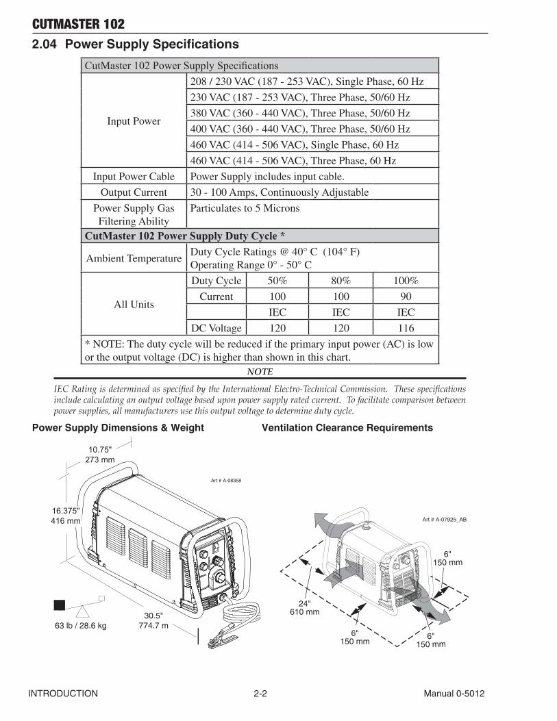
2.04 Power Supply Specifications
CutMaster 102 Power Supply Specifications
Input Power
208 / 230 VAC (187 - 253 VAC), Single Phase, 60 Hz
230 VAC (187 - 253 VAC), Three Phase, 50/60 Hz
380 VAC (360 - 440 VAC), Three Phase, 50/60 Hz
400 VAC (360 - 440 VAC), Three Phase, 50/60 Hz
460 VAC (414 - 506 VAC), Single Phase, 60 Hz
460 VAC (414 - 506 VAC), Three Phase, 60 Hz
Input Power Cable Power Supply includes input cable.
Output Current 30 - 100 Amps, Continuously Adjustable
Power Supply Gas Filtering Ability
Particulates to 5 Microns
CutMaster 102 Power Supply Duty Cycle *
Ambient TemperatureDuty Cycle Ratings @ 40° C (104° F) Operating Range 0° - 50° C
All Units
Duty Cycle 50% 80% 100%
Current 100 100 90
IEC IEC IEC
DC Voltage 120 120 116
* NOTE: The duty cycle will be reduced if the primary input power (AC) is low or the output voltage (DC) is higher than shown in this chart.
NOTE
IEC Rating is determined as specified by the International Electro-Technical Commission. These specifications include calculating an output voltage based upon power supply rated current. To facilitate comparison between power supplies, all manufacturers use this output voltage to determine duty cycle.
Power Supply Dimensions & Weight Ventilation Clearance Requirements
30.5"774.7 m63 lb / 28.6 kg
10.75"273 mm
16.375"416 mm
Art # A-08358
6"
150 mm
24"610 mm
6"150 mm
6"150 mm
Art # A-07925_AB
CUTMASTER 102
Manual 0-5012 2-3 INTRODUCTION
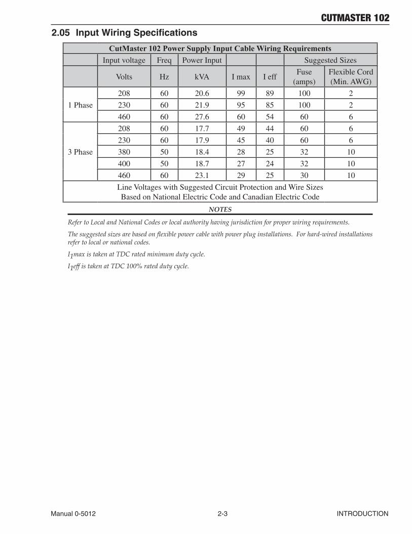
2.05 Input Wiring Specifications
CutMaster 102 Power Supply Input Cable Wiring RequirementsInput voltage Freq Power Input Suggested Sizes
Volts Hz kVA I max I effFuse
(amps)Flexible Cord (Min. AWG)
1 Phase
208 60 20.6 99 89 100 2
230 60 21.9 95 85 100 2
460 60 27.6 60 54 60 6
3 Phase
208 60 17.7 49 44 60 6
230 60 17.9 45 40 60 6
380 50 18.4 28 25 32 10
400 50 18.7 27 24 32 10
460 60 23.1 29 25 30 10
Line Voltages with Suggested Circuit Protection and Wire Sizes Based on National Electric Code and Canadian Electric Code
NOTES
Refer to Local and National Codes or local authority having jurisdiction for proper wiring requirements.
The suggested sizes are based on flexible power cable with power plug installations. For hard-wired installations refer to local or national codes.
I1max is taken at TDC rated minimum duty cycle.
I1eff is taken at TDC 100% rated duty cycle.
CUTMASTER 102
INTRODUCTION 2-4 Manual 0-5012
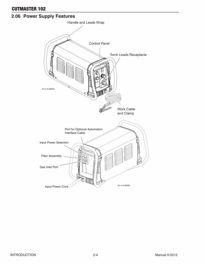
2.06 Power Supply FeaturesHandle and Leads Wrap
Torch Leads Receptacle
Control Panel
Art # A-08359
Work Cableand Clamp
Art # A-08360Input Power Cord
Port for Optional Automation Interface Cable
Gas Inlet Port
Filter Assembly
Input Power Selection
CUTMASTER 102
Manual 0-5012 2T-1 INTRODUCTION
SECTION 2 TORCH: INTRODUCTION
2T.01 Scope of ManualThis manual contains descriptions, operating instructions and maintenance procedures for the 1Torch Models MC100/Manual and MC100/Mechanized Plasma Cutting Torches. Service of this equipment is restricted to properly trained personnel; unqualified personnel are strictly cau-tioned against attempting repairs or adjustments not covered in this manual, at the risk of voiding the Warranty.Read this manual thoroughly. A complete under-standing of the characteristics and capabilities of this equipment will assure the dependable opera-tion for which it was designed.
2T.02 General DescriptionPlasma torches are similar in design to the auto-motive spark plug. They consist of negative and positive sections separated by a center insulator. Inside the torch, the pilot arc starts in the gap between the negatively charged electrode and the positively charged tip. Once the pilot arc has ionized the plasma gas, the superheated column of gas flows through the small orifice in the torch tip, which is focused on the metal to be cut.A single torch lead provides gas from a single source to be used as both the plasma and second-ary gas. The air flow is divided inside the torch head. Single - gas operation provides a smaller sized torch and inexpensive operation.
NOTE
Refer to Section 2T.05, Introduction To Plasma, for a more detailed description of plasma torch operation.
Refer to the Appendix Pages for additional specifi-cations as related to the Power Supply used.
2T.03 Specifications
A. Torch Configurations
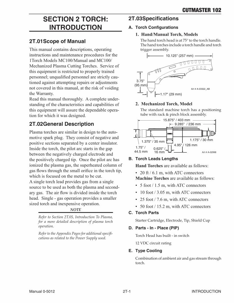
1. Hand/Manual Torch, ModelsThe hand torch head is at 75° to the torch handle. The hand torches include a torch handle and torch trigger assembly.
10.125" (257 mm)
3.75" (95 mm)
1.17" (29 mm)
Art # A-03322_AB
2. Mechanized Torch, ModelThe standard machine torch has a positioning tube with rack & pinch block assembly.
Art # A-02998
1.75" / 44.5 mm
1.375" / 35 mm
15.875" / 403 mm
0.625" /16 mm
4.95" / 126 mm
1.175" / 30 mm
9.285" / 236 mm
B. Torch Leads Lengths
Hand Torches are available as follows:• 20 ft / 6.1 m, with ATC connectorsMachine Torches are available as follows:• 5 foot / 1.5 m, with ATC connectors• 10 foot / 3.05 m, with ATC connectors• 25 foot / 7.6 m, with ATC connectors• 50 foot / 15.2 m, with ATC connectors
C. Torch Parts
Starter Cartridge, Electrode, Tip, Shield Cup
D. Parts - In - Place (PIP)
Torch Head has built - in switch
12 VDC circuit rating
E. Type Cooling
Combination of ambient air and gas stream through torch.
CUTMASTER 102
INTRODUCTION 2T-2 Manual 0-5012
F. Torch Ratings
Manual Torch Ratings
Ambient Temperature
104° F 40° C
Duty Cycle 100% @ 100 Amps @ 400 scfh
Maximum Current 120 Amps
Voltage (Vpeak) 500V
Arc Striking Voltage 7kV
Mechanized Torch Ratings
Ambient Temperature
104° F 40° C
Duty Cycle 100% @ 100 Amps @ 400 scfh
Maximum Current 120 Amps
Voltage (Vpeak) 500V
Arc Striking Voltage 7kV
G. Gas Requirements
Manual and Mechanized Torch Gas Specifications
Gas (Plasma and Secondary) Compressed Air
Operating Pressure Refer to NOTE
60 - 95 psi 4.1 - 6.5 bar
Maximum Input Pressure 125 psi / 8.6 bar
Gas Flow (Cutting and Gouging) 300 - 500 scfh 142 - 235 lpm
! WARNING
This torch is not to be used with oxygen (O2).
NOTE
Operating pressure varies with torch model, op-erating amperage, and torch leads length. Refer to gas pressure settings charts for each model.
H. Direct Contact Hazard
For standoff tip the recommended standoff is 3/16 inches / 4.7 mm.
2T.04 Options And AccessoriesFor options and accessories, see section 6.
2T.05 Introduction to Plasma
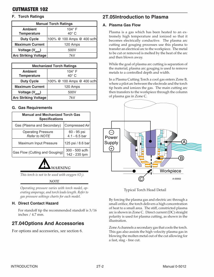
A. Plasma Gas Flow
Plasma is a gas which has been heated to an ex-tremely high temperature and ionized so that it becomes electrically conductive. The plasma arc cutting and gouging processes use this plasma to transfer an electrical arc to the workpiece. The metal to be cut or removed is melted by the heat of the arc and then blown away.
While the goal of plasma arc cutting is separation of the material, plasma arc gouging is used to remove metals to a controlled depth and width.
In a Plasma Cutting Torch a cool gas enters Zone B, where a pilot arc between the electrode and the torch tip heats and ionizes the gas. The main cutting arc then transfers to the workpiece through the column of plasma gas in Zone C.
A-00002
Workpiece
PowerSupply
+
_
C
B
A
Typical Torch Head Detail
By forcing the plasma gas and electric arc through a small orifice, the torch delivers a high concentration of heat to a small area. The stiff, constricted plasma arc is shown in Zone C. Direct current (DC) straight polarity is used for plasma cutting, as shown in the illustration.
Zone A channels a secondary gas that cools the torch. This gas also assists the high velocity plasma gas in blowing the molten metal out of the cut allowing for a fast, slag - free cut.
CUTMASTER 102
Manual 0-5012 2T-3 INTRODUCTION
B. Gas Distribution
The single gas used is internally split into plasma and secondary gases.
The plasma gas flows into the torch through the negative lead, through the starter cartridge, around the electrode, and out through the tip orifice.
The secondary gas flows down around the outside of the torch starter cartridge, and out between the tip and shield cup around the plasma arc.
C. Pilot Arc
When the torch is started a pilot arc is established between the electrode and cutting tip. This pilot arc creates a path for the main arc to transfer to the work.
D. Main Cutting Arc
DC power is also used for the main cutting arc. The negative output is connected to the torch electrode through the torch lead. The positive output is con-nected to the workpiece via the work cable and to the torch through a pilot wire.
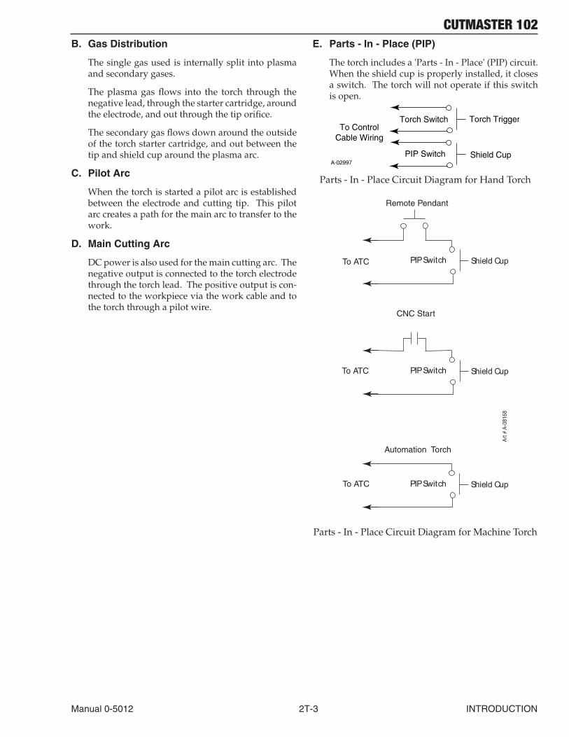
E. Parts - In - Place (PIP)
The torch includes a 'Parts - In - Place' (PIP) circuit. When the shield cup is properly installed, it closes a switch. The torch will not operate if this switch is open.
A-02997
Torch Trigger
PIP Switch Shield Cup
To ControlCable Wiring
Torch Switch
Parts - In - Place Circuit Diagram for Hand Torch
PIP Switch Shield CupTo ATC
CNC Start
PIP Switch Shield Cup
PIP Switch Shield Cup
Remote Pendant
Automation Torch
To ATC
To ATC
Art #
A-0
8168
Parts - In - Place Circuit Diagram for Machine Torch

CUTMASTER 102
INTRODUCTION 2T-4 Manual 0-5012
This Page Intentionally Blank
CUTMASTER 102
Manual 0-5012 3-1 INSTALLATION
SECTION 3 SYSTEM: INSTALLATION
3.01 Unpacking1. Use the packing lists to identify and account for each item.2. Inspect each item for possible shipping damage. If damage is evident, contact your distributor
and / or shipping company before proceeding with the installation.3. Record Power Supply and Torch model and serial numbers, purchase date and vendor name, in
the information block at the front of this manual.
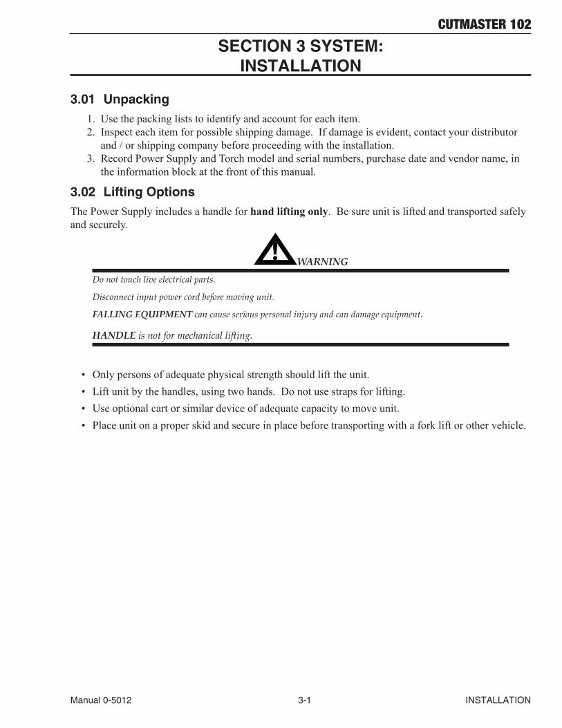
3.02 Lifting OptionsThe Power Supply includes a handle for hand lifting only. Be sure unit is lifted and transported safely and securely.
! WARNING
Do not touch live electrical parts.
Disconnect input power cord before moving unit.
FALLING EQUIPMENT can cause serious personal injury and can damage equipment.
HANDLE is not for mechanical lifting.
• Only persons of adequate physical strength should lift the unit.• Lift unit by the handles, using two hands. Do not use straps for lifting.• Use optional cart or similar device of adequate capacity to move unit.• Place unit on a proper skid and secure in place before transporting with a fork lift or other vehicle.
CUTMASTER 102
INSTALLATION 3-2 Manual 0-5012
3.03 Primary Input Power Connections
CAUTION
Check your power source for correct voltage before plugging in or connecting the unit. Check the Voltage Selector at the rear of the unit for correct setting before plugging in or connecting the unit. The primary power source, fuse, and any extension cords used must conform to local electrical code and the recommended circuit protection and wiring requirements as specified in Section 2.
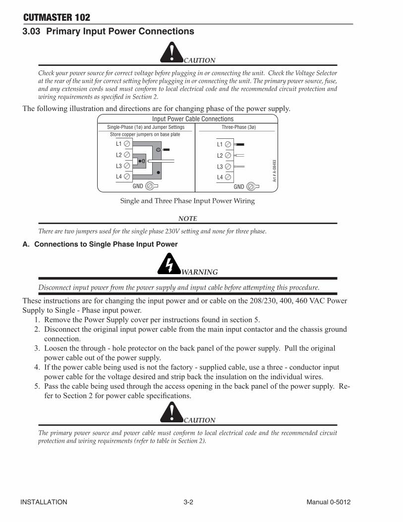
The following illustration and directions are for changing phase of the power supply.
Art #
A-0
8493
Input Power Cable ConnectionsThree-Phase (3ø)
Store copper jumpers on base plateSingle-Phase (1ø) and Jumper Settings
GND
L1
L2
L3
L4
GND
L1
L2
L3
L4
Single and Three Phase Input Power Wiring
NOTE
There are two jumpers used for the single phase 230V setting and none for three phase.
A. Connections to Single Phase Input Power
WARNING
Disconnect input power from the power supply and input cable before attempting this procedure.
These instructions are for changing the input power and or cable on the 208/230, 400, 460 VAC Power Supply to Single - Phase input power.
1. Remove the Power Supply cover per instructions found in section 5.2. Disconnect the original input power cable from the main input contactor and the chassis ground
connection.3. Loosen the through - hole protector on the back panel of the power supply. Pull the original
power cable out of the power supply.4. If the power cable being used is not the factory - supplied cable, use a three - conductor input
power cable for the voltage desired and strip back the insulation on the individual wires. 5. Pass the cable being used through the access opening in the back panel of the power supply. Re-
fer to Section 2 for power cable specifications.
CAUTION
The primary power source and power cable must conform to local electrical code and the recommended circuit protection and wiring requirements (refer to table in Section 2).
CUTMASTER 102
Manual 0-5012 3-3 INSTALLATION
6. Connect the wires as follows.• Connect Bus Bar Jumpers on the contactor as shown in prior illustration and on label in the
power supply.• Green / Yellow wire to Ground.
7. With a little slack in the wires, tighten the through - hole protector to secure the power cable.8. Reinstall the Power Supply cover.9. Connect the opposite end of individual wires to a customer supplied plug or main disconnect.10. Connect the input power cable (or close the main disconnect switch) to supply power.
B. Connections to Three Phase Input Power
WARNING
Disconnect input power from the power supply and input cable before attempting this procedure.
These instructions are for changing the input power and or cable on the 208/230, 400, 460 VAC Power Supply to Three - Phase input power.
1. Remove the Power Supply cover per instructions found in section 5.2. Disconnect the original input power cable from the main input contactor and the chassis ground
connection.3. Loosen the through - hole protector on the back panel of the power supply. Pull the original
power cable out of the power supply.4. Using a customer supplied four - conductor input power cable for the voltage desired, strip back
the insulation on the individual wires. 5. Pass the cable being used through the access opening in the back panel of the power supply. Re-
fer to Section 2 for power cable specifications.
CAUTION
The primary power source and power cable must conform to local electrical code and the recommended circuit protection and wiring requirements (refer to table in Section 2).
6. Connect the wires as follows.• Wires to L1, L2 and L3 input. It does not matter what order these wires are attached. See
previous illustration and on label in the power supply.• Green / Yellow wire to Ground.
7. With a little slack in the wires, tighten the through - hole protector to secure the power cable.8. Reinstall the Power Supply cover.9. Connect the opposite end of individual wires to a customer supplied plug or main disconnect.10. Connect the input power cable (or close the main disconnect switch) to supply power.
CUTMASTER 102
INSTALLATION 3-4 Manual 0-5012
3.04 Gas Connections
Connecting Gas Supply to Unit
The connection is the same for compressed air or high pressure cylinders. Refer to the following two subsections if an optional air line filter is to be installed.
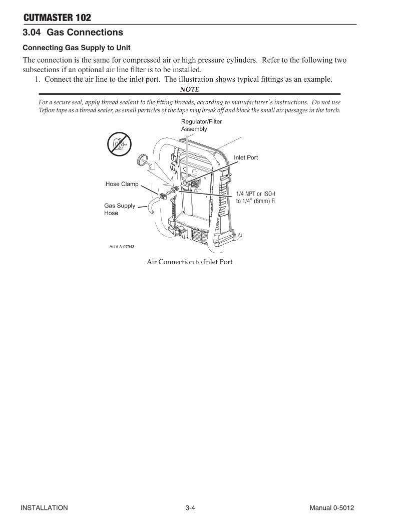
1. Connect the air line to the inlet port. The illustration shows typical fittings as an example. NOTE
For a secure seal, apply thread sealant to the fitting threads, according to manufacturer's instructions. Do not use Teflon tape as a thread sealer, as small particles of the tape may break off and block the small air passages in the torch.
Art # A-07943
Hose Clamp
Regulator/FilterAssembly
Inlet Port
Gas SupplyHose
1/4 NPT or ISO-Rto 1/4” (6mm) Fitting
Air Connection to Inlet Port
CUTMASTER 102
Manual 0-5012 3-5 INSTALLATION
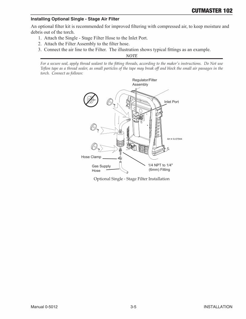
Installing Optional Single - Stage Air Filter
An optional filter kit is recommended for improved filtering with compressed air, to keep moisture and debris out of the torch.
1. Attach the Single - Stage Filter Hose to the Inlet Port.2. Attach the Filter Assembly to the filter hose.3. Connect the air line to the Filter. The illustration shows typical fittings as an example.
NOTE
For a secure seal, apply thread sealant to the fitting threads, according to the maker's instructions. Do Not use Teflon tape as a thread sealer, as small particles of the tape may break off and block the small air passages in the torch. Connect as follows:
Art # A-07944
Hose Clamp
1/4 NPT to 1/4"(6mm) Fitting
Regulator/FilterAssembly
Inlet Port
Gas SupplyHose
Optional Single - Stage Filter Installation
CUTMASTER 102
INSTALLATION 3-6 Manual 0-5012
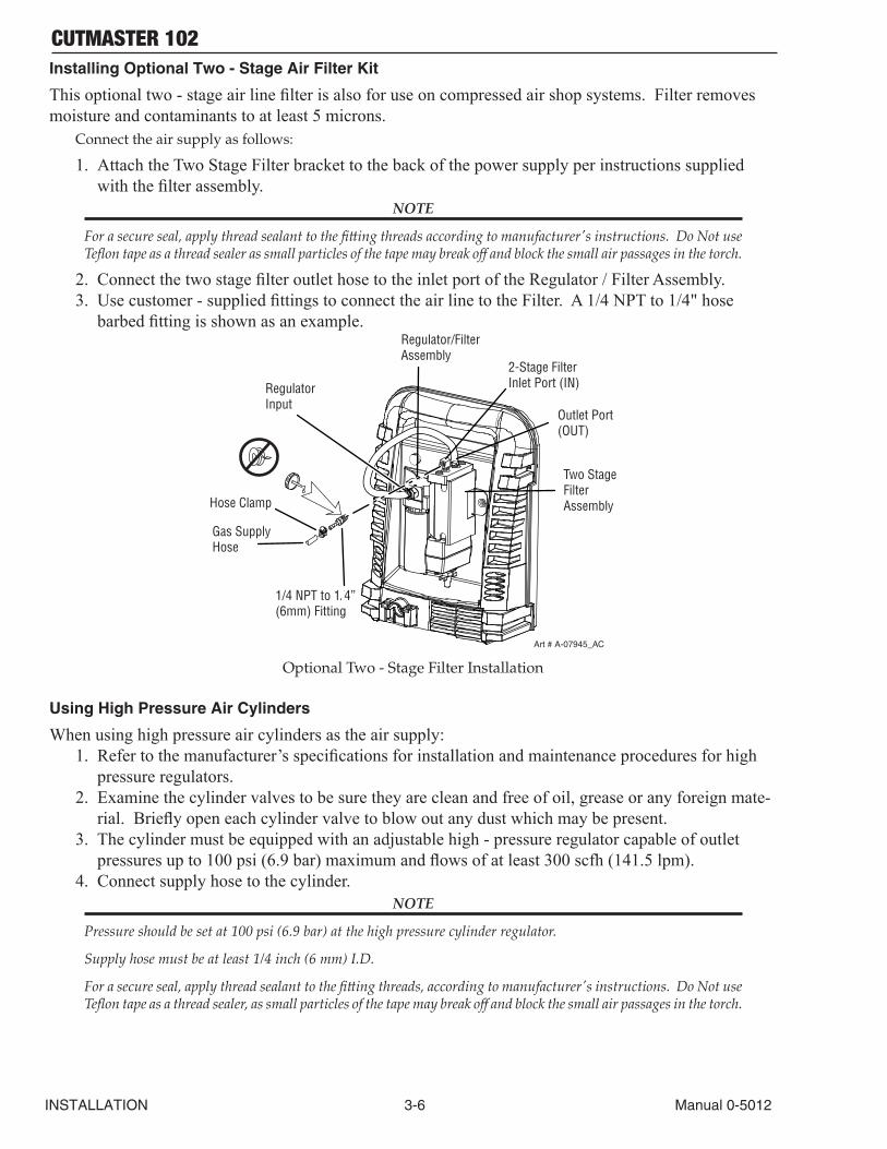
Installing Optional Two - Stage Air Filter Kit
This optional two - stage air line filter is also for use on compressed air shop systems. Filter removes moisture and contaminants to at least 5 microns.
Connect the air supply as follows:
1. Attach the Two Stage Filter bracket to the back of the power supply per instructions supplied with the filter assembly.
NOTE
For a secure seal, apply thread sealant to the fitting threads according to manufacturer's instructions. Do Not use Teflon tape as a thread sealer as small particles of the tape may break off and block the small air passages in the torch.
2. Connect the two stage filter outlet hose to the inlet port of the Regulator / Filter Assembly.3. Use customer - supplied fittings to connect the air line to the Filter. A 1/4 NPT to 1/4" hose
barbed fitting is shown as an example.
Regulator Input
Gas Supply Hose
1/4 NPT to 1/4”(6mm) Fitting
Regulator/FilterAssembly
2-Stage FilterInlet Port (IN)
Outlet Port(OUT)
Two StageFilterAssembly
Art # A-07945_AC
Hose Clamp
Optional Two - Stage Filter Installation
Using High Pressure Air Cylinders
When using high pressure air cylinders as the air supply:1. Refer to the manufacturer’s specifications for installation and maintenance procedures for high
pressure regulators.2. Examine the cylinder valves to be sure they are clean and free of oil, grease or any foreign mate-
rial. Briefly open each cylinder valve to blow out any dust which may be present.3. The cylinder must be equipped with an adjustable high - pressure regulator capable of outlet
pressures up to 100 psi (6.9 bar) maximum and flows of at least 300 scfh (141.5 lpm).4. Connect supply hose to the cylinder.
NOTE
Pressure should be set at 100 psi (6.9 bar) at the high pressure cylinder regulator.
Supply hose must be at least 1/4 inch (6 mm) I.D.
For a secure seal, apply thread sealant to the fitting threads, according to manufacturer's instructions. Do Not use Teflon tape as a thread sealer, as small particles of the tape may break off and block the small air passages in the torch.
CUTMASTER 102
Manual 0-5012 3T-1 INSTALLATION
SECTION 3 TORCH: INSTALLATION
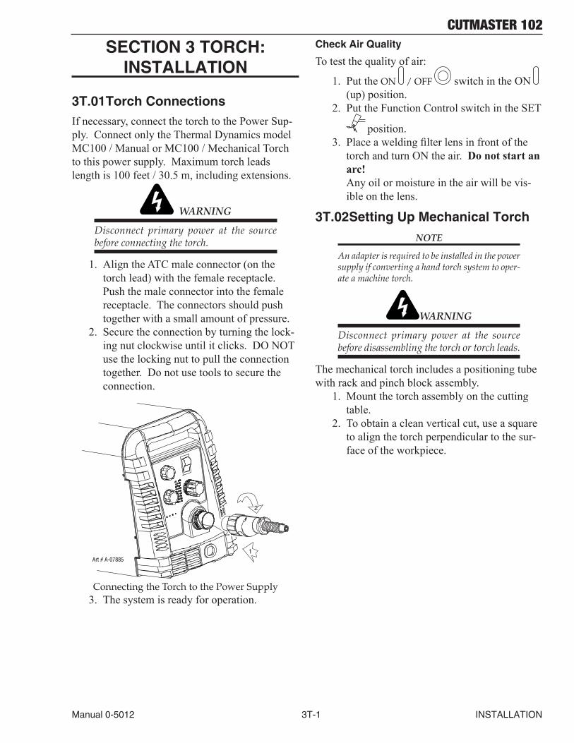
3T.01 Torch ConnectionsIf necessary, connect the torch to the Power Sup-ply. Connect only the Thermal Dynamics model MC100 / Manual or MC100 / Mechanical Torch to this power supply. Maximum torch leads length is 100 feet / 30.5 m, including extensions.
WARNING
Disconnect primary power at the source before connecting the torch.
1. Align the ATC male connector (on the torch lead) with the female receptacle. Push the male connector into the female receptacle. The connectors should push together with a small amount of pressure.
2. Secure the connection by turning the lock-ing nut clockwise until it clicks. DO NOT use the locking nut to pull the connection together. Do not use tools to secure the connection.
1
2
Art # A-07885
Connecting the Torch to the Power Supply3. The system is ready for operation.
Check Air Quality
To test the quality of air:
1. Put the ON / OFF switch in the ON (up) position.
2. Put the Function Control switch in the SET
position.3. Place a welding filter lens in front of the
torch and turn ON the air. Do not start an arc!
Any oil or moisture in the air will be vis-ible on the lens.
3T.02 Setting Up Mechanical Torch
NOTE
An adapter is required to be installed in the power supply if converting a hand torch system to oper-ate a machine torch.
WARNING
Disconnect primary power at the source before disassembling the torch or torch leads.
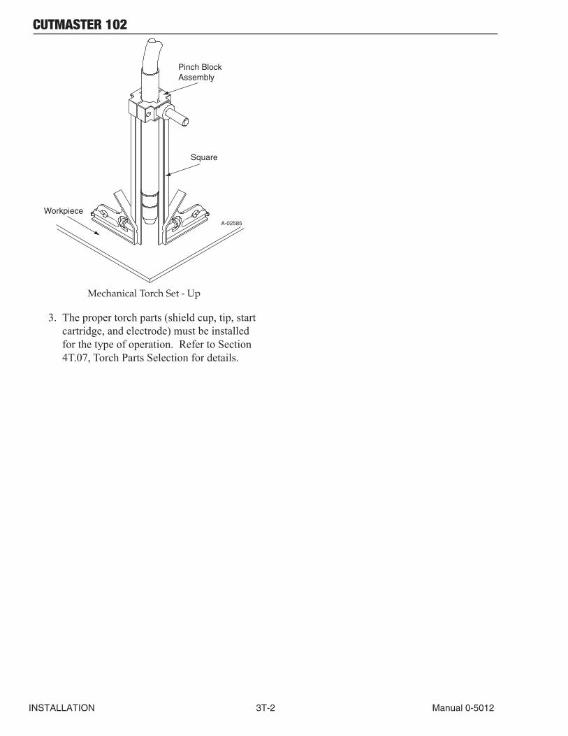
The mechanical torch includes a positioning tube with rack and pinch block assembly.
1. Mount the torch assembly on the cutting table.
2. To obtain a clean vertical cut, use a square to align the torch perpendicular to the sur-face of the workpiece.
CUTMASTER 102
INSTALLATION 3T-2 Manual 0-5012
A-02585
Workpiece
Square
Pinch BlockAssembly
Mechanical Torch Set - Up
3. The proper torch parts (shield cup, tip, start cartridge, and electrode) must be installed for the type of operation. Refer to Section 4T.07, Torch Parts Selection for details.
CUTMASTER 102
Manual 0-5012 4-1 OPERATION
SECTION 4 SYSTEM: OPERATION
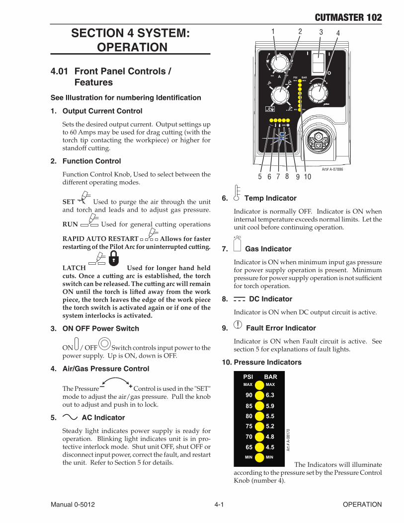
4.01 Front Panel Controls / Features
See Illustration for numbering Identification
1. Output Current Control
Sets the desired output current. Output settings up to 60 Amps may be used for drag cutting (with the torch tip contacting the workpiece) or higher for standoff cutting.
2. Function Control
Function Control Knob, Used to select between the different operating modes.
SET Used to purge the air through the unit and torch and leads and to adjust gas pressure.
RUN Used for general cutting operations
RAPID AUTO RESTART Allows for faster restarting of the Pilot Arc for uninterrupted cutting.
LATCH Used for longer hand held cuts. Once a cutting arc is established, the torch switch can be released. The cutting arc will remain ON until the torch is lifted away from the work piece, the torch leaves the edge of the work piece the torch switch is activated again or if one of the system interlocks is activated.
3. ON OFF Power Switch
ON / OFF Switch controls input power to the power supply. Up is ON, down is OFF.
4. Air/Gas Pressure Control
The Pressure + Control is used in the "SET" mode to adjust the air/gas pressure. Pull the knob out to adjust and push in to lock.
5. AC Indicator
Steady light indicates power supply is ready for operation. Blinking light indicates unit is in pro-tective interlock mode. Shut unit OFF, shut OFF or disconnect input power, correct the fault, and restart the unit. Refer to Section 5 for details.
A+
PSI BARMAX MAX
MIN MIN
!
1 2 3 4
5 6 7 8 9Art# A-07886
MIN MAX
10
6. Temp Indicator
Indicator is normally OFF. Indicator is ON when internal temperature exceeds normal limits. Let the unit cool before continuing operation.
7. Gas Indicator
Indicator is ON when minimum input gas pressure for power supply operation is present. Minimum pressure for power supply operation is not sufficient for torch operation.
8. DC Indicator
Indicator is ON when DC output circuit is active.
9. ! Fault Error Indicator
Indicator is ON when Fault circuit is active. See section 5 for explanations of fault lights.
10. Pressure Indicators
PSI BARMAX MAX
MIN MIN
8075
70
65
5.585 5.9
90 6.3
5.2
4.8
4.5 Art #
A-0
8170
The Indicators will illuminate according to the pressure set by the Pressure Control Knob (number 4).
CUTMASTER 102
OPERATION 4-2 Manual 0-5012
4.02 Preparations for OperationAt the start of each operating session:
WARNING
Disconnect primary power at the source be-fore assembling or disassembling power sup-ply, torch parts, or torch and leads assemblies.
Torch Parts Selection
Check the torch for proper assembly and appropriate torch parts. The torch parts must correspond with the type of operation, and with the amperage output of this Power Supply (100 amps maximum). Refer to Section 4T.07 and following for torch parts selection.
Torch Connection
Check that the torch is properly connected. Only Thermal Dynamics model MC100 / Manual or MC100 / Mechanical Torches may be connected to this Power Supply. See Section 3T of this manual.
Check Primary Input Power Source
1. Check the power source for proper input voltage. Make sure the input power source meets the power requirements for the unit per Section 2, Specifications.
2. Connect the input power cable (or close the main disconnect switch) to supply power to the system.
Air Source
Ensure source meets requirements (refer to Section 2). Check connections and turn air supply ON.
Connect Work Cable
Clamp the work cable to the workpiece or cutting table. The area must be free from oil, paint and rust. Connect only to the main part of the workpiece; do not connect to the part to be cut off.
Art # A-04509
Power ON
Place the Power Supply ON / OFF switch to the ON (up) position. AC indicator turns ON.
Gas indicator turns ON if there is sufficient gas pressure for power supply operation and the cool-ing fans turn ON.
NOTE
Minimum pressure for power supply operation is lower than minimum for torch operation.
The cooling fans will turn ON as soon as the unit is turned ON. After the unit is idle for ten (10) minutes the fans will turn OFF. The fans will come back ON as soon as the torch switch (Start Signal) is activated or if the unit is turned OFF, then turned ON again. If an over temperature condition occurs, the fans will continue to run while the condition exists and for a ten (10) min-ute period once the condition is cleared.
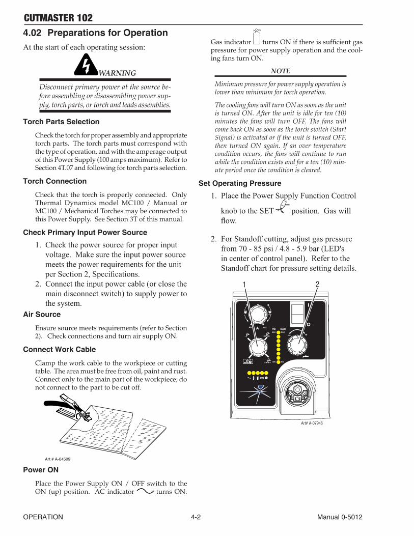
Set Operating Pressure
1. Place the Power Supply Function Control
knob to the SET position. Gas will flow.
2. For Standoff cutting, adjust gas pressure from 70 - 85 psi / 4.8 - 5.9 bar (LED's in center of control panel). Refer to the Standoff chart for pressure setting details.
A+
PSI BARMAX MAX
MIN MIN
!
1 2
Art# A-07946
MIN MAX
CUTMASTER 102
Manual 0-5012 4-3 OPERATION
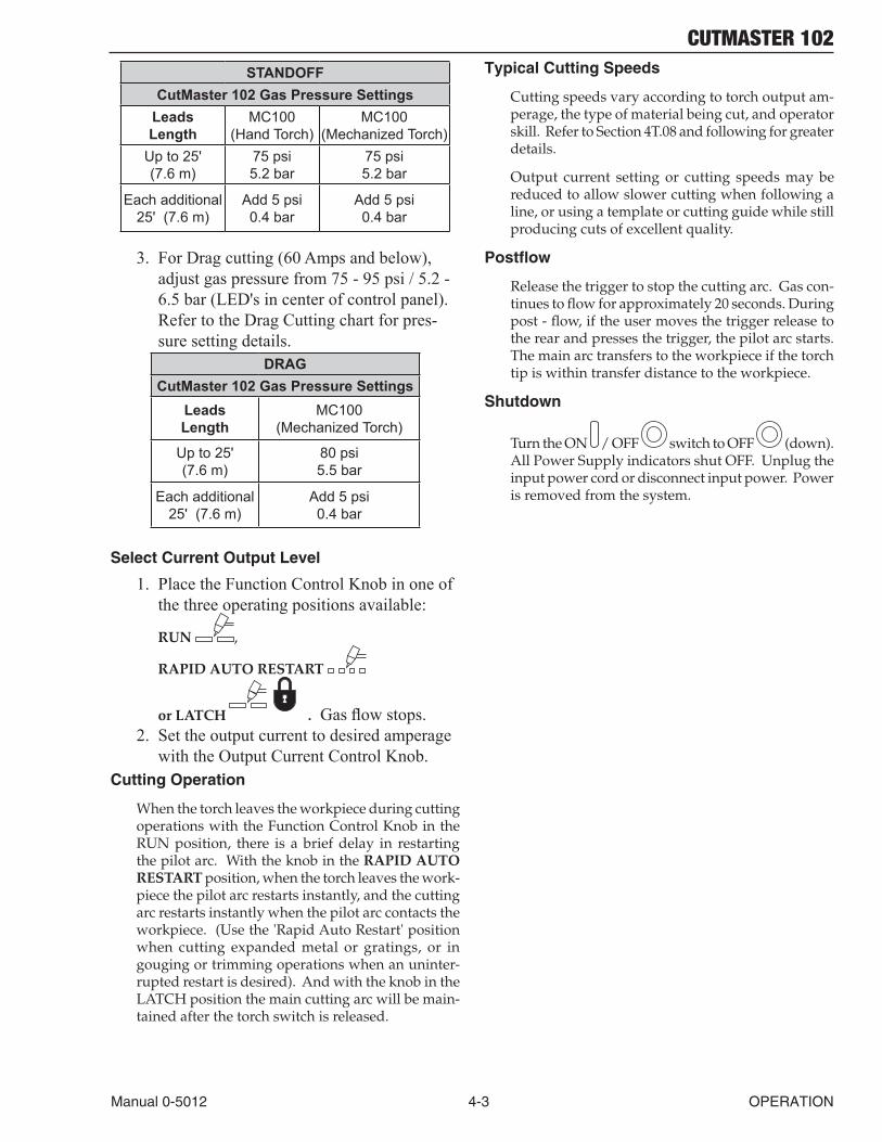
STANDOFFCutMaster 102 Gas Pressure Settings
Leads Length
MC100 (Hand Torch)
MC100 (Mechanized Torch)
Up to 25' (7.6 m)
75 psi 5.2 bar
75 psi 5.2 bar
Each additional 25' (7.6 m)
Add 5 psi 0.4 bar
Add 5 psi 0.4 bar
3. For Drag cutting (60 Amps and below), adjust gas pressure from 75 - 95 psi / 5.2 - 6.5 bar (LED's in center of control panel). Refer to the Drag Cutting chart for pres-sure setting details.
DRAGCutMaster 102 Gas Pressure Settings
Leads Length
MC100 (Mechanized Torch)
Up to 25' (7.6 m)
80 psi 5.5 bar
Each additional 25' (7.6 m)
Add 5 psi 0.4 bar
Select Current Output Level
1. Place the Function Control Knob in one of the three operating positions available:
RUN ,
RAPID AUTO RESTART
or LATCH . Gas flow stops.2. Set the output current to desired amperage
with the Output Current Control Knob.Cutting Operation
When the torch leaves the workpiece during cutting operations with the Function Control Knob in the RUN position, there is a brief delay in restarting the pilot arc. With the knob in the RAPID AUTO RESTART position, when the torch leaves the work-piece the pilot arc restarts instantly, and the cutting arc restarts instantly when the pilot arc contacts the workpiece. (Use the 'Rapid Auto Restart' position when cutting expanded metal or gratings, or in gouging or trimming operations when an uninter-rupted restart is desired). And with the knob in the LATCH position the main cutting arc will be main-tained after the torch switch is released.
Typical Cutting Speeds
Cutting speeds vary according to torch output am-perage, the type of material being cut, and operator skill. Refer to Section 4T.08 and following for greater details.
Output current setting or cutting speeds may be reduced to allow slower cutting when following a line, or using a template or cutting guide while still producing cuts of excellent quality.
Postflow
Release the trigger to stop the cutting arc. Gas con-tinues to flow for approximately 20 seconds. During post - flow, if the user moves the trigger release to the rear and presses the trigger, the pilot arc starts. The main arc transfers to the workpiece if the torch tip is within transfer distance to the workpiece.
Shutdown
Turn the ON / OFF switch to OFF (down). All Power Supply indicators shut OFF. Unplug the input power cord or disconnect input power. Power is removed from the system.

CUTMASTER 102
OPERATION 4-4 Manual 0-5012
This Page Intentionally Blank
CUTMASTER 102
Manual 0-5012 4T-1 OPERATION
SECTION 4 TORCH: OPERATION
4T.01 Torch Parts SelectionDepending on the type of operation to be done determines the torch parts to be used.
Type of operation:Drag cutting, standoff cutting or gouging
Torch parts:Shield Cup, Cutting Tip, Electrode and Starter Cartridge
NOTE
Refer to Section 4T.07 and following for additional information on torch parts.
Change the torch parts for a different operation as follows:
WARNING
Disconnect primary power at the source be-fore assembling or disassembling torch parts, or torch and leads assemblies.
NOTE
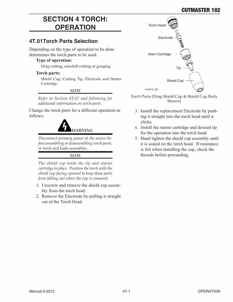
The shield cup holds the tip and starter cartridge in place. Position the torch with the shield cup facing upward to keep these parts from falling out when the cup is removed.
1. Unscrew and remove the shield cup assem-bly from the torch head.
2. Remove the Electrode by pulling it straight out of the Torch Head.
A-03510_AB
Electrode
Start Cartridge
Tip
Shield Cup
Torch Head
Torch Parts (Drag Shield Cap & Shield Cup Body Shown)
3. Install the replacement Electrode by push-ing it straight into the torch head until it clicks.
4. Install the starter cartridge and desired tip for the operation into the torch head.
5. Hand tighten the shield cup assembly until it is seated on the torch head. If resistance is felt when installing the cup, check the threads before proceeding.
CUTMASTER 102
OPERATION 4T-2 Manual 0-5012
4T.02 Cut Quality
NOTES
Cut quality depends heavily on setup and parameters such as torch standoff, alignment with the workpiece, cutting speed, gas pressures, and operator ability.
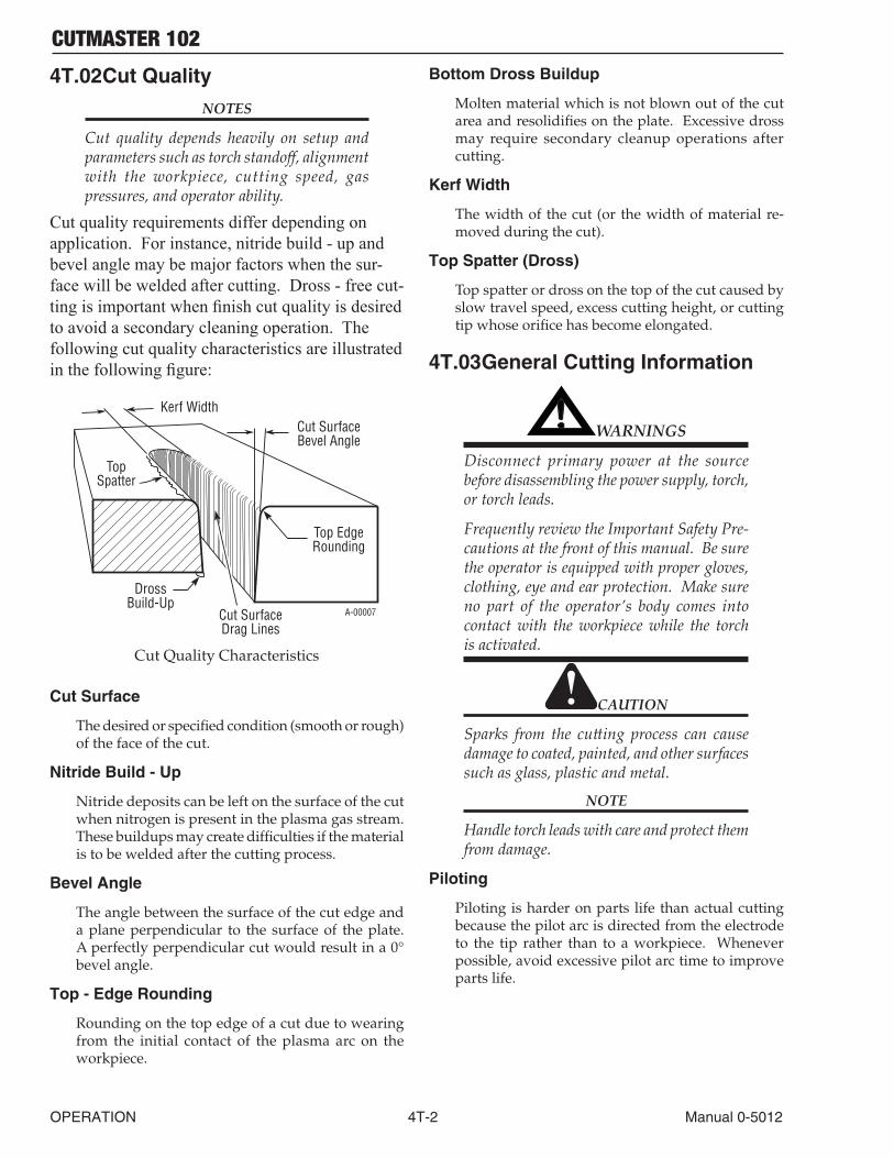
Cut quality requirements differ depending on application. For instance, nitride build - up and bevel angle may be major factors when the sur-face will be welded after cutting. Dross - free cut-ting is important when finish cut quality is desired to avoid a secondary cleaning operation. The following cut quality characteristics are illustrated in the following figure:
Kerf WidthCut SurfaceBevel Angle
Top EdgeRounding
Cut SurfaceDrag Lines
DrossBuild-Up
TopSpatter
A-00007
Cut Quality Characteristics
Cut Surface
The desired or specified condition (smooth or rough) of the face of the cut.
Nitride Build - Up
Nitride deposits can be left on the surface of the cut when nitrogen is present in the plasma gas stream. These buildups may create difficulties if the material is to be welded after the cutting process.
Bevel Angle
The angle between the surface of the cut edge and a plane perpendicular to the surface of the plate. A perfectly perpendicular cut would result in a 0° bevel angle.
Top - Edge Rounding
Rounding on the top edge of a cut due to wearing from the initial contact of the plasma arc on the workpiece.
Bottom Dross Buildup
Molten material which is not blown out of the cut area and resolidifies on the plate. Excessive dross may require secondary cleanup operations after cutting.
Kerf Width
The width of the cut (or the width of material re-moved during the cut).
Top Spatter (Dross)
Top spatter or dross on the top of the cut caused by slow travel speed, excess cutting height, or cutting tip whose orifice has become elongated.
4T.03 General Cutting Information
! WARNINGS
Disconnect primary power at the source before disassembling the power supply, torch, or torch leads.
Frequently review the Important Safety Pre-cautions at the front of this manual. Be sure the operator is equipped with proper gloves, clothing, eye and ear protection. Make sure no part of the operator’s body comes into contact with the workpiece while the torch is activated.
CAUTION
Sparks from the cutting process can cause damage to coated, painted, and other surfaces such as glass, plastic and metal.
NOTE
Handle torch leads with care and protect them from damage.
Piloting
Piloting is harder on parts life than actual cutting because the pilot arc is directed from the electrode to the tip rather than to a workpiece. Whenever possible, avoid excessive pilot arc time to improve parts life.
CUTMASTER 102
Manual 0-5012 4T-3 OPERATION
Torch Standoff
Improper standoff (the distance between the torch tip and workpiece) can adversely affect tip life as well as shield cup life. Standoff may also signifi-cantly affect the bevel angle. Reducing standoff will generally result in a more square cut.
Edge Starting
For edge starts, hold the torch perpendicular to the workpiece with the front of the tip near (not touch-ing) the edge of the workpiece at the point where the cut is to start. When starting at the edge of the plate, do not pause at the edge and force the arc to "reach" for the edge of the metal. Establish the cut-ting arc as quickly as possible.
Direction of Cut
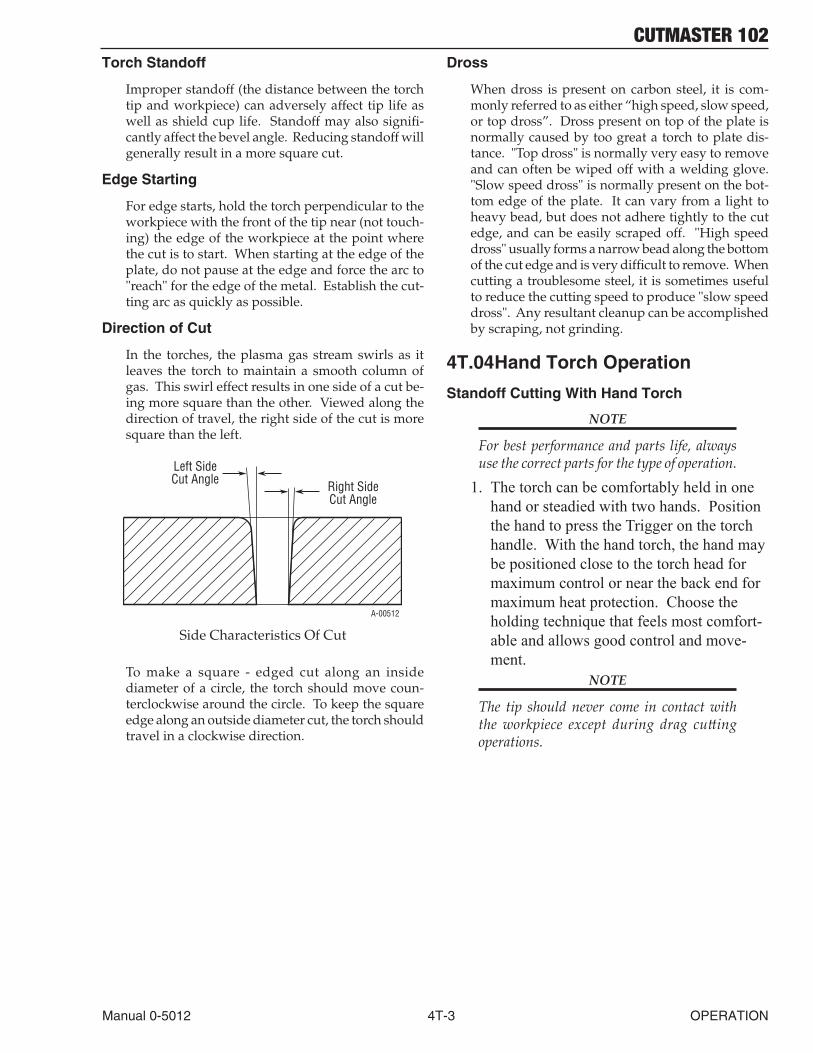
In the torches, the plasma gas stream swirls as it leaves the torch to maintain a smooth column of gas. This swirl effect results in one side of a cut be-ing more square than the other. Viewed along the direction of travel, the right side of the cut is more square than the left.
Right SideCut Angle
Left SideCut Angle
A-00512
Side Characteristics Of Cut
To make a square - edged cut along an inside diameter of a circle, the torch should move coun-terclockwise around the circle. To keep the square edge along an outside diameter cut, the torch should travel in a clockwise direction.
Dross
When dross is present on carbon steel, it is com-monly referred to as either “high speed, slow speed, or top dross”. Dross present on top of the plate is normally caused by too great a torch to plate dis-tance. "Top dross" is normally very easy to remove and can often be wiped off with a welding glove. "Slow speed dross" is normally present on the bot-tom edge of the plate. It can vary from a light to heavy bead, but does not adhere tightly to the cut edge, and can be easily scraped off. "High speed dross" usually forms a narrow bead along the bottom of the cut edge and is very difficult to remove. When cutting a troublesome steel, it is sometimes useful to reduce the cutting speed to produce "slow speed dross". Any resultant cleanup can be accomplished by scraping, not grinding.
4T.04 Hand Torch Operation
Standoff Cutting With Hand Torch
NOTE
For best performance and parts life, always use the correct parts for the type of operation.
1. The torch can be comfortably held in one hand or steadied with two hands. Position the hand to press the Trigger on the torch handle. With the hand torch, the hand may be positioned close to the torch head for maximum control or near the back end for maximum heat protection. Choose the holding technique that feels most comfort-able and allows good control and move-ment.
NOTE
The tip should never come in contact with the workpiece except during drag cutting operations.

CUTMASTER 102
OPERATION 4T-4 Manual 0-5012
2. Depending on the cutting operation, do one of the following:a. For edge starts, hold the torch perpen-
dicular to the workpiece with the front of the tip on the edge of the workpiece at the point where the cut is to start.
b. For standoff cutting, hold the torch 1/8 - 3/8 in (3-9 mm) from the workpiece as shown below.
A-00024_AB
Shield Cup
Torch
Standoff Distance1/8" - 3/8" (3 - 9mm)
Standoff Distance
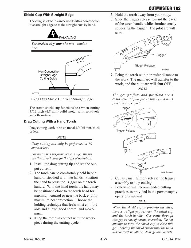
3. Hold the torch away from your body.4. Slide the trigger release toward the back
of the torch handle while simultaneously squeezing the trigger. The pilot arc will start.
A-02986
Trigger
Trigger Release
5. Bring the torch within transfer distance to the work. The main arc will transfer to the work, and the pilot arc will shut OFF.
NOTE
The gas preflow and postflow are a characteristic of the power supply and not a function of the torch.
3
4
Art # A-03383
Trigger
21
Trigger Release
6. Cut as usual. Simply release the trigger assembly to stop cutting.
7. Follow normal recommended cutting practices as provided in the power supply operator's manual.
NOTE
When the shield cup is properly installed, there is a slight gap between the shield cup and the torch handle. Gas vents through this gap as part of normal operation. Do not attempt to force the shield cup to close this gap. Forcing the shield cup against the torch head or torch handle can damage components.
8. For a consistent standoff height from the workpiece, install the standoff guide by sliding it onto the torch shield cup. Install the guide with the legs at the sides of the shield cup body to maintain good visibility of the cutting arc. During operation, posi-tion the legs of the standoff guide against the workpiece.
Shield Cup
Workpiece
Standoff Guide
Art # A-04034
Torch Tip
CUTMASTER 102
Manual 0-5012 4T-5 OPERATION
Shield Cup With Straight Edge
The drag shield cup can be used with a non conduc-tive straight edge to make straight cuts by hand.
WARNING
The straight edge must be non - conduc-tive.
A-03539
Non-ConductiveStraight EdgeCutting Guide
Using Drag Shield Cup With Straight Edge
The crown shield cup functions best when cutting 3/16 inch (4.7 mm) solid metal with relatively smooth surface.
Drag Cutting With a Hand Torch
Drag cutting works best on metal 1/4" (6 mm) thick or less.
NOTE
Drag cutting can only be performed at 60 amps or less.
For best parts performance and life, always use the correct parts for the type of operation.
1. Install the drag cutting tip and set the out-put current.
2. The torch can be comfortably held in one hand or steadied with two hands. Position the hand to press the Trigger on the torch handle. With the hand torch, the hand may be positioned close to the torch head for maximum control or near the back end for maximum heat protection. Choose the holding technique that feels most comfort-able and allows good control and move-ment.
4. Keep the torch in contact with the work-piece during the cutting cycle.
5. Hold the torch away from your body.6. Slide the trigger release toward the back
of the torch handle while simultaneously squeezing the trigger. The pilot arc will start.
A-02986
Trigger
Trigger Release
7. Bring the torch within transfer distance to the work. The main arc will transfer to the work, and the pilot arc will shut OFF.
NOTE
The gas preflow and postflow are a characteristic of the power supply and not a function of the torch.
3
4
Art # A-03383
Trigger
21
Trigger Release
8. Cut as usual. Simply release the trigger assembly to stop cutting.
9. Follow normal recommended cutting practices as provided in the power supply operator's manual.
NOTE
When the shield cup is properly installed, there is a slight gap between the shield cup and the torch handle. Gas vents through this gap as part of normal operation. Do not attempt to force the shield cup to close this gap. Forcing the shield cup against the torch head or torch handle can damage components.

CUTMASTER 102
OPERATION 4T-6 Manual 0-5012
Piercing With Hand Torch
1. The torch can be comfortably held in one hand or steadied with two hands. Position the hand to press the Trigger on the torch handle. With the hand torch, the hand may be positioned close to the torch head for maximum control or near the back end for maximum heat protection. Choose the technique that feels most comfortable and allows good control and movement.
NOTE
The tip should never come in contact with the workpiece except during drag cutting operations.
2. Angle the torch slightly to direct blowback particles away from the torch tip (and op-erator) rather than directly back into it until the pierce is complete.
3. In a portion of the unwanted metal start the pierce off the cutting line and then continue the cut onto the line. Hold the torch per-pendicular to the workpiece after the pierce is complete.
4. Hold the torch away from your body.5. Slide the trigger release toward the back
of the torch handle while simultaneously squeezing the trigger. The pilot arc will start.
A-02986
Trigger
Trigger Release
6. Bring the torch within transfer distance to the work. The main arc will transfer to the work, and the pilot arc will shut OFF.
NOTES
The gas preflow and postflow are a characteristic of the power supply and not a function of the torch.
When the shield cup is properly installed, there is a slight gap between the shield cup and the torch handle. Gas vents through this gap as part of normal operation. Do not attempt to force the shield cup to close this gap. Forcing the shield cup against the torch head or torch handle can damage components.
7. Clean spatter and scale from the shield cup and the tip as soon as possible. Spraying the shield cup in anti - spatter compound will minimize the amount of scale which adheres to it.
Cutting speed depends on material, thickness, and the operator’s ability to accurately follow the desired cut line. The following factors may have an impact on system performance:
• Torch parts wear• Air quality• Line voltage fluctuations• Torch standoff height• Proper work cable connection
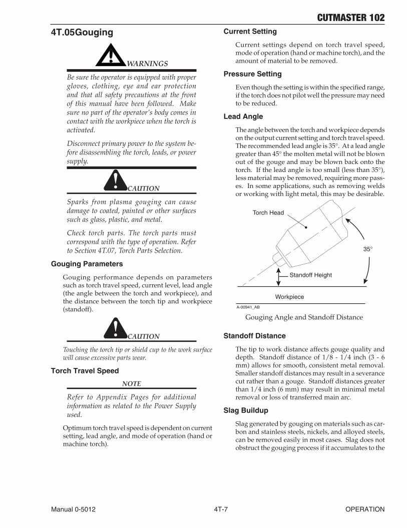
CUTMASTER 102
Manual 0-5012 4T-7 OPERATION
4T.05 Gouging
! WARNINGS
Be sure the operator is equipped with proper gloves, clothing, eye and ear protection and that all safety precautions at the front of this manual have been followed. Make sure no part of the operator’s body comes in contact with the workpiece when the torch is activated.
Disconnect primary power to the system be-fore disassembling the torch, leads, or power supply.
CAUTION
Sparks from plasma gouging can cause damage to coated, painted or other surfaces such as glass, plastic, and metal.
Check torch parts. The torch parts must correspond with the type of operation. Refer to Section 4T.07, Torch Parts Selection.
Gouging Parameters
Gouging performance depends on parameters such as torch travel speed, current level, lead angle (the angle between the torch and workpiece), and the distance between the torch tip and workpiece (standoff).
CAUTION
Touching the torch tip or shield cup to the work surface will cause excessive parts wear.
Torch Travel Speed
NOTE
Refer to Appendix Pages for additional information as related to the Power Supply used.
Optimum torch travel speed is dependent on current setting, lead angle, and mode of operation (hand or machine torch).
Current Setting
Current settings depend on torch travel speed, mode of operation (hand or machine torch), and the amount of material to be removed.
Pressure Setting
Even though the setting is within the specified range, if the torch does not pilot well the pressure may need to be reduced.
Lead Angle
The angle between the torch and workpiece depends on the output current setting and torch travel speed. The recommended lead angle is 35°. At a lead angle greater than 45° the molten metal will not be blown out of the gouge and may be blown back onto the torch. If the lead angle is too small (less than 35°), less material may be removed, requiring more pass-es. In some applications, such as removing welds or working with light metal, this may be desirable.
35°
Workpiece
Torch Head
Standoff Height
A-00941_AB
Gouging Angle and Standoff Distance
Standoff Distance
The tip to work distance affects gouge quality and depth. Standoff distance of 1/8 - 1/4 inch (3 - 6 mm) allows for smooth, consistent metal removal. Smaller standoff distances may result in a severance cut rather than a gouge. Standoff distances greater than 1/4 inch (6 mm) may result in minimal metal removal or loss of transferred main arc.
Slag Buildup
Slag generated by gouging on materials such as car-bon and stainless steels, nickels, and alloyed steels, can be removed easily in most cases. Slag does not obstruct the gouging process if it accumulates to the
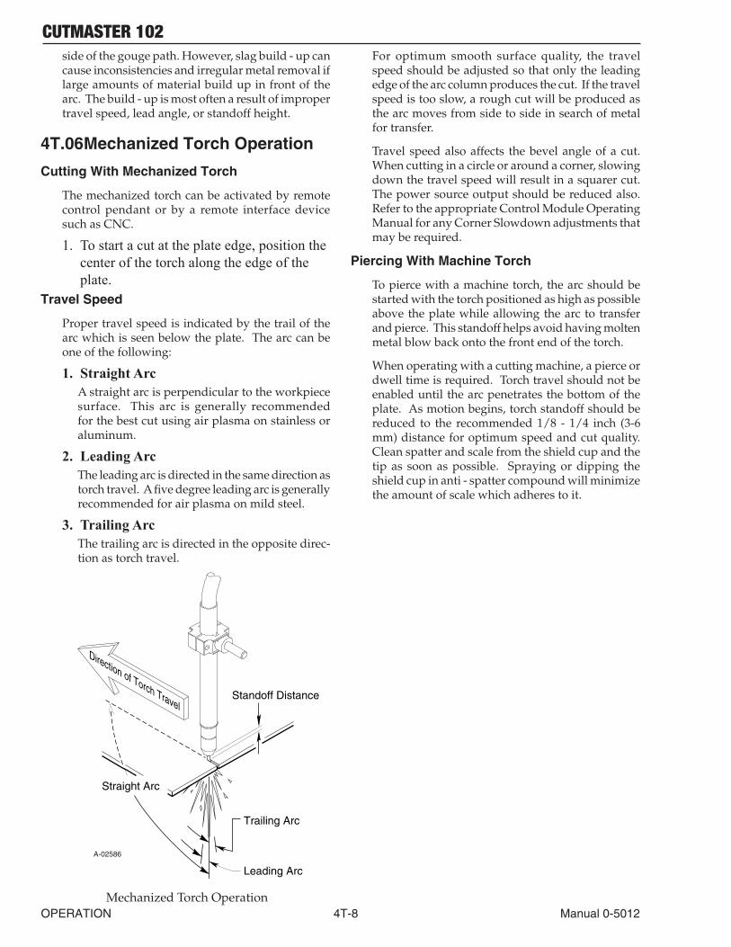
CUTMASTER 102
OPERATION 4T-8 Manual 0-5012
side of the gouge path. However, slag build - up can cause inconsistencies and irregular metal removal if large amounts of material build up in front of the arc. The build - up is most often a result of improper travel speed, lead angle, or standoff height.
4T.06 Mechanized Torch Operation
Cutting With Mechanized Torch
The mechanized torch can be activated by remote control pendant or by a remote interface device such as CNC.
1. To start a cut at the plate edge, position the center of the torch along the edge of the plate.
Travel Speed
Proper travel speed is indicated by the trail of the arc which is seen below the plate. The arc can be one of the following:
1. Straight ArcA straight arc is perpendicular to the workpiece surface. This arc is generally recommended for the best cut using air plasma on stainless or aluminum.
2. Leading ArcThe leading arc is directed in the same direction as torch travel. A five degree leading arc is generally recommended for air plasma on mild steel.
3. Trailing ArcThe trailing arc is directed in the opposite direc-tion as torch travel.
Standoff Distance
Straight Arc
Trailing Arc
Leading Arc
Direction of Torch Travel
A-02586
Mechanized Torch Operation
For optimum smooth surface quality, the travel speed should be adjusted so that only the leading edge of the arc column produces the cut. If the travel speed is too slow, a rough cut will be produced as the arc moves from side to side in search of metal for transfer.
Travel speed also affects the bevel angle of a cut. When cutting in a circle or around a corner, slowing down the travel speed will result in a squarer cut. The power source output should be reduced also. Refer to the appropriate Control Module Operating Manual for any Corner Slowdown adjustments that may be required.
Piercing With Machine Torch
To pierce with a machine torch, the arc should be started with the torch positioned as high as possible above the plate while allowing the arc to transfer and pierce. This standoff helps avoid having molten metal blow back onto the front end of the torch.
When operating with a cutting machine, a pierce or dwell time is required. Torch travel should not be enabled until the arc penetrates the bottom of the plate. As motion begins, torch standoff should be reduced to the recommended 1/8 - 1/4 inch (3-6 mm) distance for optimum speed and cut quality. Clean spatter and scale from the shield cup and the tip as soon as possible. Spraying or dipping the shield cup in anti - spatter compound will minimize the amount of scale which adheres to it.

CUTMASTER 102
Manual 0-5012 4T-9 OPERATION
4T.07 Parts Selection for MC100 Torch Cutting
StartCartridge64006513
Electrode64006514
Tips:
30A 64006506 40A 64006507 60A 64006526
Shield Cap, Gouging 64006524
40A 64006508
60A 64006510
Shield Cap, Drag50-60A 64006521
Shield Cup Body,64006523
60A
40A
Shield Cap, Deflector64006525
Shield Cup Body,64006523
Shield Cup 64006515
Tip:
Tips:
Tips:
DRAG TIP CUTTING
60-100AGOUGING
CUTTING
CUTTING
Art # A-08130
Shield Cap, Deflector64006525
Shield Cup Body,64006523
Shield Cup 64006515
O-Ring No. 8-3488
Standoff Guide 64006528
STANDOFF CUTTING
DRAG SHIELD CUTTING
DRAG SHIELD CUTTING
STANDOFF CUTTING
Shield Cap, Deflector64006525
Shield Cup Body,64006523
Shield Cup 64006515
Standoff Guide64006528
Part # Output Range Depth WidthTip A 64006516 40 Amps Max. Shallow NarrowTip B 64006517 60-100 Amps Deep NarrowTip C 64006518 60-100 Amps Moderate ModerateTip D 64006519 60-100 Amps Shallow Wide
Gouging Profiles
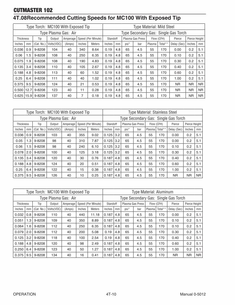
CUTMASTER 102
OPERATION 4T-10 Manual 0-5012
4T.08 Recommended Cutting Speeds for MC100 With Exposed Tip
Type Torch: MC100 With Exposed Tip Type Material: Mild SteelType Plasma Gas: Air Type Secondary Gas: Single Gas Torch
Thickness Tip Output Amperage Speed(PerMinute) Standoff Plasma Gas Press Flow(CFH) Pierce PierceHeight
Inches mm (Cat.No.) Volts(VDC) (Amps) Inches Meters Inches mm psi* bar Plasma Total** Delay(Sec) Inches mm
0.036 0.9 9-8208 104 40 340 8.64 0.19 4.8 65 4.5 55 170 0.00 0.2 5.1
0.06 1.5 9-8208 108 40 250 6.35 0.19 4.8 65 4.5 55 170 0.10 0.2 5.1
0.075 1.9 9-8208 108 40 190 4.83 0.19 4.8 65 4.5 55 170 0.30 0.2 5.1
0.135 3.4 9-8208 110 40 105 2.67 0.19 4.8 65 4.5 55 170 0.40 0.2 5.1
0.188 4.8 9-8208 113 40 60 1.52 0.19 4.8 65 4.5 55 170 0.60 0.2 5.1
0.25 6.4 9-8208 111 40 40 1.02 0.19 4.8 65 4.5 55 170 1.00 0.2 5.1
0.375 9.5 9-8208 124 40 21 0.53 0.19 4.8 65 4.5 55 170 NR NR NR
0.500 12.7 9-8208 123 40 11 0.28 0.19 4.8 65 4.5 55 170 NR NR NR
0.625 15.9 9-8208 137 40 7 0.18 0.19 4.8 65 4.5 55 170 NR NR NR
Type Torch: MC100 With Exposed Tip Type Material: Stainless SteelType Plasma Gas: Air Type Secondary Gas: Single Gas Torch
Thickness Tip Output Amperage Speed(PerMinute) Standoff Plasma Gas Press Flow(CFH) Pierce PierceHeight
Inches mm (Cat.No.) Volts(VDC) (Amps) Inches Meters Inches mm psi* bar Plasma Total** Delay(Sec) Inches mm
0.036 0.9 9-8208 103 40 355 9.02 0.125 3.2 65 4.5 55 170 0.00 0.2 5.1
0.05 1.3 9-8208 98 40 310 7.87 0.125 3.2 65 4.5 55 170 0.00 0.2 5.1
0.06 1.5 9-8208 98 40 240 6.10 0.125 3.2 65 4.5 55 170 0.10 0.2 5.1
0.078 2.0 9-8208 100 40 125 3.18 0.125 3.2 65 4.5 55 170 0.30 0.2 5.1
0.135 3.4 9-8208 120 40 30 0.76 0.187 4.8 65 4.5 55 170 0.40 0.2 5.1
0.188 4.8 9-8208 124 40 20 0.51 0.187 4.8 65 4.5 55 170 0.60 0.2 5.1
0.25 6.4 9-8208 122 40 15 0.38 0.187 4.8 65 4.5 55 170 1.00 0.2 5.1
0.375 9.5 9-8208 126 40 10 0.25 0.187 4.8 65 4.5 55 170 NR NR NR
Type Torch: MC100 With Exposed Tip Type Material: AluminumType Plasma Gas: Air Type Secondary Gas: Single Gas Torch
Thickness Tip Output Amperage Speed(PerMinute) Standoff Plasma Gas Press Flow(CFH) Pierce PierceHeight
Inches mm (Cat.No.) Volts(VDC) (Amps) Inches Meters Inches mm psi* bar Plasma Total** Delay(Sec) Inches mm
0.032 0.8 9-8208 110 40 440 11.18 0.187 4.8 65 4.5 55 170 0.00 0.2 5.1
0.051 1.3 9-8208 109 40 350 8.89 0.187 4.8 65 4.5 55 170 0.10 0.2 5.1
0.064 1.6 9-8208 112 40 250 6.35 0.187 4.8 65 4.5 55 170 0.10 0.2 5.1
0.079 2.0 9-8208 112 40 200 5.08 0.19 4.8 65 4.5 55 170 0.30 0.2 5.1
0.125 3.2 9-8208 118 40 100 2.54 0.19 4.8 65 4.5 55 170 0.40 0.2 5.1
0.188 4.8 9-8208 120 40 98 2.49 0.187 4.8 65 4.5 55 170 0.60 0.2 5.1
0.250 6.4 9-8208 123 40 50 1.27 0.187 4.8 65 4.5 55 170 1.00 0.2 5.1
0.375 9.5 9-8208 134 40 16 0.41 0.187 4.8 65 4.5 55 170 NR NR NR

CUTMASTER 102
Manual 0-5012 4T-11 OPERATION
Type Torch: MC100 With Exposed Tip Type Material: Mild SteelType Plasma Gas: Air Type Secondary Gas: Single Gas Torch
Thickness Tip Output Amperage Speed(PerMinute) Standoff Plasma Gas Press Flow(CFH) Pierce PierceHeight
Inches mm (Cat.No.) Volts(VDC) (Amps) Inches Meters Inches mm psi* bar Plasma Total** Delay(Sec) Inches mm
0.060 1.5 9-8210 110 60 290 7.37 0.19 4.8 70 4.8 90 245 0.00 0.19 4.8
0.075 1.9 9-8210 120 60 285 7.24 0.19 4.8 70 4.8 90 245 0.10 0.19 4.8
0.120 3.0 9-8210 120 60 180 4.57 0.19 4.8 70 4.8 90 245 0.10 0.19 4.8
0.135 3.4 9-8210 119 60 170 4.32 0.19 4.8 70 4.8 90 245 0.10 0.19 4.8
0.188 4.8 9-8210 121 60 100 2.54 0.19 4.8 70 4.8 90 245 0.20 0.19 4.8
0.250 6.4 9-8210 119 60 80 2.03 0.19 4.8 70 4.8 90 245 0.30 0.19 4.8
0.375 9.5 9-8210 124 60 50 1.27 0.19 4.8 70 4.8 90 245 0.50 0.19 4.8
0.500 12.7 9-8210 126 60 26 0.66 0.19 4.8 70 4.8 90 245 0.75 0.19 4.8
0.625 15.9 9-8210 127 60 19 0.48 0.19 4.8 70 4.8 90 245 NR NR NR
0.750 19.1 9-8210 134 60 14 0.36 0.19 4.8 70 4.8 90 245 NR NR NR
1.000 25.4 9-8210 140 60 6 0.15 0.19 4.8 70 4.8 90 245 NR NR NR
Type Torch: MC100 With Exposed Tip Type Material: Stainless SteelType Plasma Gas: Air Type Secondary Gas: Single Gas Torch
Thickness Tip Output Amperage Speed(PerMinute) Standoff Plasma Gas Press Flow(CFH) Pierce PierceHeight
Inches mm (Cat.No.) Volts(VDC) (Amps) Inches Meters Inches mm psi* bar Plasma Total** Delay(Sec) Inches mm
0.06 1.5 9-8210 119 60 350 8.91 0.19 4.8 70 4.8 90 245 0.00 0.20 5.1
0.075 1.9 9-8210 116 60 300 7.64 0.19 4.8 70 4.8 90 245 0.10 0.20 5.1
0.120 3.0 9-8210 123 60 150 3.82 0.19 4.8 70 4.8 90 245 0.10 0.20 5.1
0.135 3.4 9-8210 118 60 125 3.18 0.19 4.8 70 4.8 90 245 0.10 0.20 5.1
0.188 4.8 9-8210 122 60 90 2.29 0.19 4.8 70 4.8 90 245 0.20 0.20 5.1
0.250 6.4 9-8210 120 60 65 1.65 0.19 4.8 70 4.8 90 245 0.30 0.20 5.1
0.375 9.5 9-8210 130 60 30 0.76 0.19 4.8 70 4.8 90 245 0.50 0.20 5.1
0.500 12.7 9-8210 132 60 21 0.53 0.19 4.8 70 4.8 90 245 0.75 0.20 5.1
0.625 15.9 9-8210 130 60 15 0.38 0.19 4.8 70 4.8 90 245 NR NR NR
0.750 19.1 9-8210 142 60 12 0.31 0.25 6.4 70 4.8 90 245 NR NR NR
Type Torch: MC100 With Exposed Tip Type Material: AluminumType Plasma Gas: Air Type Secondary Gas: Single Gas Torch
Thickness Tip Output Amperage Speed(PerMinute) Standoff Plasma Gas Press Flow(CFH) Pierce PierceHeight
Inches mm (Cat.No.) Volts(VDC) (Amps) Inches Meters Inches mm psi* bar Plasma Total** Delay(Sec) Inches mm
0.060 1.5 9-8210 110 60 440 11.18 0.25 6.4 70 4.8 90 245 0.00 0.25 6.4
0.075 1.9 9-8210 110 60 440 11.18 0.25 6.4 70 4.8 90 245 0.10 0.25 6.4
0.120 3.0 9-8210 116 60 250 6.35 0.25 6.4 70 4.8 90 245 0.10 0.25 6.4
0.188 3.4 9-8210 116 60 170 4.32 0.25 6.4 70 4.8 90 245 0.20 0.25 6.4
0.250 6.4 9-8210 132 60 85 2.16 0.25 6.4 70 4.8 90 245 0.30 0.25 6.4
0.375 9.5 9-8210 140 60 45 1.14 0.25 6.4 70 4.8 90 245 0.50 0.25 6.4
0.500 12.7 9-8210 143 60 30 0.76 0.25 6.4 70 4.8 90 245 0.80 0.25 6.4
0.625 15.9 9-8210 145 60 20 0.51 0.25 6.4 70 4.8 90 245 NR NR NR
0.750 19.1 9-8210 145 60 18 0.46 0.25 6.4 70 4.8 90 245 NR NR NR
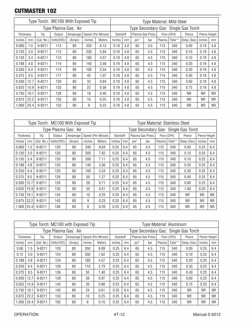
CUTMASTER 102
OPERATION 4T-12 Manual 0-5012
Type Torch: MC100 With Exposed Tip Type Material: Mild SteelType Plasma Gas: Air Type Secondary Gas: Single Gas Torch
Thickness Tip Output Amperage Speed(PerMinute) Standoff Plasma Gas Press Flow(CFH) Pierce PierceHeight
Inches mm (Cat.No.) Volts(VDC) (Amps) Inches Meters Inches mm psi* bar Plasma Total** Delay(Sec) Inches mm
0.060 1.5 9-8211 113 80 320 8.13 0.19 4.8 65 4.5 115 340 0.00 0.19 4.8
0.120 3.0 9-8211 113 80 230 5.84 0.19 4.8 65 4.5 115 340 0.10 0.19 4.8
0.135 3.4 9-8211 115 80 180 4.57 0.19 4.8 65 4.5 115 340 0.10 0.19 4.8
0.188 4.8 9-8211 114 80 140 3.56 0.19 4.8 65 4.5 115 340 0.20 0.19 4.8
0.250 6.4 9-8211 114 80 100 2.54 0.19 4.8 65 4.5 115 340 0.30 0.19 4.8
0.375 9.5 9-8211 117 80 42 1.07 0.19 4.8 65 4.5 115 340 0.40 0.19 4.8
0.500 12.7 9-8211 120 80 33 0.84 0.19 4.8 65 4.5 115 340 0.60 0.19 4.8
0.625 15.9 9-8211 133 80 22 0.56 0.19 4.8 65 4.5 115 340 0.75 0.19 4.8
0.750 19.1 9-8211 128 80 18 0.46 0.19 4.8 65 4.5 115 340 NR NR NR
0.875 22.2 9-8211 133 80 10 0.25 0.19 4.8 65 4.5 115 340 NR NR NR
1.000 25.4 9-8211 132 80 9 0.23 0.19 4.8 65 4.5 115 340 NR NR NR
Type Torch: MC100 With Exposed Tip Type Material: Stainless SteelType Plasma Gas: Air Type Secondary Gas: Single Gas Torch
Thickness Tip Output Amperage Speed(PerMinute) Standoff Plasma Gas Press Flow(CFH) Pierce PierceHeight
Inches mm (Cat.No.) Volts(VDC) (Amps) Inches Meters Inches mm psi* bar Plasma Total** Delay(Sec) Inches mm
0.060 1.5 9-8211 120 80 340 8.64 0.25 6.4 65 4.5 115 340 0.00 0.25 6.4
0.120 3.0 9-8211 120 80 300 7.62 0.25 6.4 65 4.5 115 340 0.10 0.25 6.4
0.135 3.4 9-8211 120 80 280 7.11 0.25 6.4 65 4.5 115 340 0.10 0.25 6.4
0.188 4.8 9-8211 120 80 140 3.56 0.25 6.4 65 4.5 115 340 0.20 0.25 6.4
0.250 6.4 9-8211 120 80 100 2.54 0.25 6.4 65 4.5 115 340 0.30 0.25 6.4
0.375 9.5 9-8211 126 80 50 1.27 0.25 6.4 65 4.5 115 340 0.40 0.25 6.4
0.500 12.7 9-8211 129 80 28 0.71 0.25 6.4 65 4.5 115 340 0.80 0.25 6.4
0.625 15.9 9-8211 135 80 20 0.51 0.25 6.4 65 4.5 115 340 1.00 0.25 6.4
0.750 19.1 9-8211 143 80 10 0.25 0.25 6.4 65 4.5 115 340 NR NR NR
0.875 22.2 9-8211 143 80 9 0.23 0.25 6.4 65 4.5 115 340 NR NR NR
1.000 25.4 9-8211 146 80 8 0.20 0.25 6.4 65 4.5 115 340 NR NR NR
Type Torch: MC100 with Exposed Tip Type Material: AluminumType Plasma Gas: Air Type Secondary Gas: Single Gas Torch
Thickness Tip Output Amperage Speed(PerMinute) Standoff Plasma Gas Press Flow(CFH) Pierce PierceHeight
Inches mm (Cat.No.) Volts(VDC) (Amps) Inches Meters Inches mm psi* bar Plasma Total** Delay(Sec) Inches mm
0.06 1.5 9-8211 120 80 350 8.89 0.25 6.4 65 4.5 115 340 0.00 0.25 6.4
0.12 3.0 9-8211 124 80 300 7.62 0.25 6.4 65 4.5 115 340 0.10 0.25 6.4
0.188 4.8 9-8211 124 80 180 4.57 0.25 6.4 65 4.5 115 340 0.20 0.25 6.4
0.250 6.4 9-8211 128 80 110 2.79 0.25 6.4 65 4.5 115 340 0.30 0.25 6.4
0.375 9.5 9-8211 136 80 55 1.40 0.25 6.4 65 4.5 115 340 0.40 0.25 6.4
0.500 12.7 9-8211 139 80 38 0.97 0.25 6.4 65 4.5 115 340 0.60 0.25 6.4
0.625 15.9 9-8211 142 80 26 0.66 0.25 6.4 65 4.5 115 340 0.75 0.25 6.4
0.750 19.1 9-8211 145 80 24 0.61 0.25 6.4 65 4.5 115 340 NR NR NR
0.875 22.2 9-8211 153 80 10 0.25 0.25 6.4 65 4.5 115 340 NR NR NR
1.000 25.4 9-8211 162 80 6 0.15 0.25 6.4 65 4.5 115 340 NR NR NR

CUTMASTER 102
Manual 0-5012 4T-13 OPERATION
Type Torch: MC100 With Exposed Tip Type Material: Mild SteelType Plasma Gas: Air Type Secondary Gas: Single Gas Torch
Thickness Tip Output Amperage Speed(PerMinute) Standoff Plasma Gas Press Flow(CFH) Pierce PierceHeight
Inches mm (Cat.No.) Volts(VDC) (Amps) Inches Meters Inches mm psi* bar Plasma Total** Delay(Sec) Inches mm
0.250 6.4 9-8212 110 100 105 2.65 0.190 4.8 75 5.2 130 390 0.4 0.200 5.1
0.375 9.5 9-8212 117 100 70 1.75 0.190 4.8 75 5.2 130 390 0.5 0.200 5.1
0.500 12.7 9-8212 120 100 50 1.25 0.190 4.8 75 5.2 130 390 0.6 0.200 5.1
0.625 15.9 9-8212 125 100 35 0.90 0.190 4.8 75 5.2 130 390 1.0 0.200 5.1
0.750 19.0 9-8212 131 100 18 0.45 0.190 4.8 75 5.2 130 390 2.0 0.250 6.4
1.000 25.4 9-8212 135 100 10 0.25 0.190 4.8 75 5.2 130 390 NR NR NR
Type Torch: MC100 With Exposed Tip Type Material: Stainless SteelType Plasma Gas: Air Type Secondary Gas: Single Gas Torch
Thickness Tip Output Amperage Speed(PerMinute) Standoff Plasma Gas Press Flow(CFH) Pierce PierceHeight
Inches mm (Cat.No.) Volts(VDC) (Amps) Inches Meters Inches mm psi* bar Plasma Total** Delay(Sec) Inches mm
0.250 6.4 9-8212 118 100 90 2.30 0.190 4.8 75 5.2 130 390 0.5 0.250 6.4
0.375 9.5 9-8212 122 100 55 1.40 0.190 4.8 75 5.2 130 390 0.8 0.250 6.4
0.500 12.7 9-8212 126 100 30 0.75 0.190 4.8 75 5.2 130 390 1.0 0.250 6.4
0.625 15.9 9-8212 133 100 20 0.50 0.190 4.8 75 5.2 130 390 1.5 0.250 6.4
0.750 19.0 9-8212 138 100 15 0.40 0.190 4.8 75 5.2 130 390 NR NR NR
1.000 25.4 9-8212 139 100 10 0.25 0.190 4.8 75 5.2 130 390 NR NR NR
Type Torch: MC100 with Exposed Tip Type Material: AluminumType Plasma Gas: Air Type Secondary Gas: Single Gas Torch
Thickness Tip Output Amperage Speed(PerMinute) Standoff Plasma Gas Press Flow(CFH) Pierce PierceHeight
Inches mm (Cat.No.) Volts(VDC) (Amps) Inches Meters Inches mm psi* bar Plasma Total** Delay(Sec) Inches mm
0.250 6.4 9-8212 108 100 120 3.05 0.190 4.8 65 4.5 120 360 0.2 0.225 5.7
0.375 9.5 9-8212 117 100 65 1.65 0.190 4.8 65 4.5 120 360 0.4 0.225 5.7
0.500 12.7 9-8212 120 100 45 1.15 0.190 4.8 65 4.5 120 360 0.5 0.225 5.7
0.625 15.9 9-8212 125 100 30 0.75 0.190 4.8 65 4.5 120 360 0.8 0.225 5.7
0.750 19.0 9-8212 131 100 25 0.65 0.190 4.8 65 4.5 120 360 1.0 0.225 5.7
1.000 25.4 9-8212 140 100 10 0.25 0.190 4.8 65 4.5 120 360 NR NR NR
NOTES
* Gas pressure shown is for torches with leads up to 25’ / 7.6 m long. For 50’ / 15.2 m leads, set gas pressure to 70 psi / 4.8 bar. ** Total flow rate includes plasma and secondary gas flow.
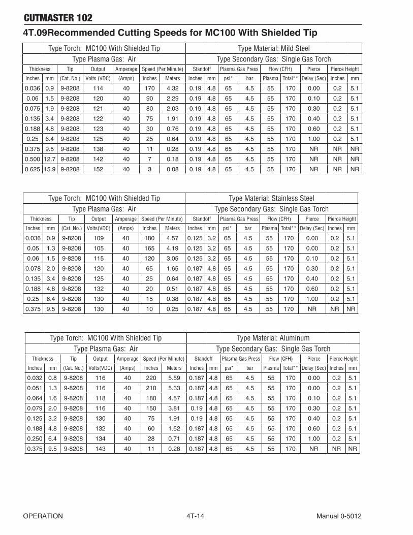
CUTMASTER 102
OPERATION 4T-14 Manual 0-5012
4T.09 Recommended Cutting Speeds for MC100 With Shielded Tip
Type Torch: MC100 With Shielded Tip Type Material: Mild SteelType Plasma Gas: Air Type Secondary Gas: Single Gas Torch
Thickness Tip Output Amperage Speed(PerMinute) Standoff Plasma Gas Press Flow(CFH) Pierce PierceHeight
Inches mm (Cat.No.) Volts(VDC) (Amps) Inches Meters Inches mm psi* bar Plasma Total** Delay(Sec) Inches mm
0.036 0.9 9-8208 114 40 170 4.32 0.19 4.8 65 4.5 55 170 0.00 0.2 5.1
0.06 1.5 9-8208 120 40 90 2.29 0.19 4.8 65 4.5 55 170 0.10 0.2 5.1
0.075 1.9 9-8208 121 40 80 2.03 0.19 4.8 65 4.5 55 170 0.30 0.2 5.1
0.135 3.4 9-8208 122 40 75 1.91 0.19 4.8 65 4.5 55 170 0.40 0.2 5.1
0.188 4.8 9-8208 123 40 30 0.76 0.19 4.8 65 4.5 55 170 0.60 0.2 5.1
0.25 6.4 9-8208 125 40 25 0.64 0.19 4.8 65 4.5 55 170 1.00 0.2 5.1
0.375 9.5 9-8208 138 40 11 0.28 0.19 4.8 65 4.5 55 170 NR NR NR
0.500 12.7 9-8208 142 40 7 0.18 0.19 4.8 65 4.5 55 170 NR NR NR
0.625 15.9 9-8208 152 40 3 0.08 0.19 4.8 65 4.5 55 170 NR NR NR
Type Torch: MC100 With Shielded Tip Type Material: Stainless SteelType Plasma Gas: Air Type Secondary Gas: Single Gas Torch
Thickness Tip Output Amperage Speed(PerMinute) Standoff Plasma Gas Press Flow(CFH) Pierce PierceHeight
Inches mm (Cat.No.) Volts(VDC) (Amps) Inches Meters Inches mm psi* bar Plasma Total** Delay(Sec) Inches mm
0.036 0.9 9-8208 109 40 180 4.57 0.125 3.2 65 4.5 55 170 0.00 0.2 5.1
0.05 1.3 9-8208 105 40 165 4.19 0.125 3.2 65 4.5 55 170 0.00 0.2 5.1
0.06 1.5 9-8208 115 40 120 3.05 0.125 3.2 65 4.5 55 170 0.10 0.2 5.1
0.078 2.0 9-8208 120 40 65 1.65 0.187 4.8 65 4.5 55 170 0.30 0.2 5.1
0.135 3.4 9-8208 125 40 25 0.64 0.187 4.8 65 4.5 55 170 0.40 0.2 5.1
0.188 4.8 9-8208 132 40 20 0.51 0.187 4.8 65 4.5 55 170 0.60 0.2 5.1
0.25 6.4 9-8208 130 40 15 0.38 0.187 4.8 65 4.5 55 170 1.00 0.2 5.1
0.375 9.5 9-8208 130 40 10 0.25 0.187 4.8 65 4.5 55 170 NR NR NR
Type Torch: MC100 With Shielded Tip Type Material: AluminumType Plasma Gas: Air Type Secondary Gas: Single Gas Torch
Thickness Tip Output Amperage Speed(PerMinute) Standoff Plasma Gas Press Flow(CFH) Pierce PierceHeight
Inches mm (Cat.No.) Volts(VDC) (Amps) Inches Meters Inches mm psi* bar Plasma Total** Delay(Sec) Inches mm
0.032 0.8 9-8208 116 40 220 5.59 0.187 4.8 65 4.5 55 170 0.00 0.2 5.1
0.051 1.3 9-8208 116 40 210 5.33 0.187 4.8 65 4.5 55 170 0.00 0.2 5.1
0.064 1.6 9-8208 118 40 180 4.57 0.187 4.8 65 4.5 55 170 0.10 0.2 5.1
0.079 2.0 9-8208 116 40 150 3.81 0.19 4.8 65 4.5 55 170 0.30 0.2 5.1
0.125 3.2 9-8208 130 40 75 1.91 0.19 4.8 65 4.5 55 170 0.40 0.2 5.1
0.188 4.8 9-8208 132 40 60 1.52 0.187 4.8 65 4.5 55 170 0.60 0.2 5.1
0.250 6.4 9-8208 134 40 28 0.71 0.187 4.8 65 4.5 55 170 1.00 0.2 5.1
0.375 9.5 9-8208 143 40 11 0.28 0.187 4.8 65 4.5 55 170 NR NR NR

CUTMASTER 102
Manual 0-5012 4T-15 OPERATION
Type Torch: MC100 With Shielded Tip Type Material: Mild SteelType Plasma Gas: Air Type Secondary Gas: Single Gas Torch
Thickness Tip Output Amperage Speed(PerMinute) Standoff Plasma Gas Press Flow(CFH) Pierce PierceHeight
Inches mm (Cat.No.) Volts(VDC) (Amps) Inches Meters Inches mm psi* bar Plasma Total** Delay(Sec) Inches mm
0.060 1.5 9-8210 124 60 250 6.35 0.19 4.8 70 4.8 90 245 0.00 0.2 5.1
0.075 1.9 9-8210 126 60 237 6.02 0.19 4.8 70 4.8 90 245 0.10 0.2 5.1
0.120 3.0 9-8210 126 60 230 5.84 0.19 4.8 70 4.8 90 245 0.10 0.2 5.1
0.135 3.4 9-8210 128 60 142 3.61 0.19 4.8 70 4.8 90 245 0.10 0.2 5.1
0.188 4.8 9-8210 128 60 125 3.18 0.19 4.8 70 4.8 90 245 0.20 0.2 5.1
0.250 6.4 9-8210 123 60 80 2.03 0.19 4.8 70 4.8 90 245 0.30 0.2 5.1
0.375 9.5 9-8210 132 60 34 0.86 0.19 4.8 70 4.8 90 245 0.50 0.2 5.1
0.500 12.7 9-8210 137 60 23 0.58 0.19 4.8 70 4.8 90 245 0.75 0.2 5.1
0.625 15.9 9-8210 139 60 14 0.36 0.19 4.8 70 4.8 90 245 NR NR NR
0.750 19.1 9-8210 145 60 14 0.36 0.19 4.8 70 4.8 90 245 NR NR NR
1.000 25.4 9-8210 156 60 4 0.10 0.19 4.8 70 4.8 90 245 NR NR NR
Type Torch: MC100 With Shielded Tip Type Material: Stainless SteelType Plasma Gas: Air Type Secondary Gas: Single Gas Torch
Thickness Tip Output Amperage Speed(PerMinute) Standoff Plasma Gas Press Flow(CFH) Pierce PierceHeight
Inches mm (Cat.No.) Volts(VDC) (Amps) Inches Meters Inches mm psi* bar Plasma Total** Delay(Sec) Inches mm
0.06 1.5 9-8210 110 60 165 4.19 0.13 3.2 70 4.8 90 245 0.00 0.20 5.1
0.075 1.9 9-8210 116 60 155 3.94 0.13 3.2 70 4.8 90 245 0.10 0.20 5.1
0.120 3.0 9-8210 115 60 125 3.18 0.13 3.2 70 4.8 90 245 0.10 0.20 5.1
0.135 3.4 9-8210 118 60 80 2.03 0.13 3.2 70 4.8 90 245 0.10 0.20 5.1
0.188 4.8 9-8210 120 60 75 1.91 0.13 3.2 70 4.8 90 245 0.20 0.20 5.1
0.250 6.4 9-8210 121 60 60 1.52 0.13 3.2 70 4.8 90 245 0.30 0.20 5.1
0.375 9.5 9-8210 129 60 28 0.71 0.13 3.2 70 4.8 90 245 0.50 0.20 5.1
0.500 12.7 9-8210 135 60 17 0.43 0.19 4.8 70 4.8 90 245 0.75 0.20 5.1
0.625 15.9 9-8210 135 60 14 0.36 0.19 4.8 70 4.8 90 245 NR NR NR
0.750 19.1 9-8210 142 60 10 0.25 0.19 4.8 70 4.8 90 245 NR NR NR
Type Torch: MC100 With Shielded Tip Type Material: AluminumType Plasma Gas: Air Type Secondary Gas: Single Gas Torch
Thickness Tip Output Amperage Speed(PerMinute) Standoff Plasma Gas Press Flow(CFH) Pierce PierceHeight
Inches mm (Cat.No.) Volts(VDC) (Amps) Inches Meters Inches mm psi* bar Plasma Total** Delay(Sec) Inches mm
0.060 1.5 9-8210 105 60 350 8.89 0.13 3.2 70 4.8 90 245 0.00 0.20 5.1
0.075 1.9 9-8210 110 60 350 8.89 0.13 3.2 70 4.8 90 245 0.10 0.20 5.1
0.120 3.0 9-8210 110 60 275 6.99 0.13 3.2 70 4.8 90 245 0.10 0.20 5.1
0.188 3.4 9-8210 122 60 140 3.56 0.13 3.2 70 4.8 90 245 0.20 0.20 5.1
0.250 6.4 9-8210 134 60 80 2.03 0.19 4.8 70 4.8 90 245 0.30 0.20 5.1
0.375 9.5 9-8210 140 60 45 1.14 0.19 4.8 70 4.8 90 245 0.50 0.20 5.1
0.500 12.7 9-8210 144 60 26 0.66 0.19 4.8 70 4.8 90 245 0.80 0.20 5.1
0.625 15.9 9-8210 145 60 19 0.48 0.19 4.8 70 4.8 90 245 NR NR NR
0.750 19.1 9-8210 150 60 15 0.38 0.19 4.8 70 4.8 90 245 NR NR NR

CUTMASTER 102
OPERATION 4T-16 Manual 0-5012
Type Torch: MC100 With Shielded Tip Type Material: Mild SteelType Plasma Gas: Air Type Secondary Gas: Single Gas Torch
Thickness Tip Output Amperage Speed(PerMinute) Standoff Plasma Gas Press Flow(CFH) Pierce PierceHeight
Inches mm (Cat.No.) Volts(VDC) (Amps) Inches Meters Inches mm psi* bar Plasma Total** Delay(Sec) Inches mm
0.060 1.5 9-8211 128 80 280 7.11 0.19 4.8 65 4.5 115 340 0.00 0.2 5.1
0.120 3.0 9-8211 126 80 203 5.16 0.19 4.8 65 4.5 115 340 0.10 0.2 5.1
0.135 3.4 9-8211 128 80 182 4.62 0.19 4.8 65 4.5 115 340 0.10 0.2 5.1
0.188 4.8 9-8211 128 80 137 3.48 0.19 4.8 65 4.5 115 340 0.20 0.2 5.1
0.250 6.4 9-8211 131 80 100 2.54 0.19 4.8 65 4.5 115 340 0.30 0.2 5.1
0.375 9.5 9-8211 134 80 40 1.02 0.19 4.8 65 4.5 115 340 0.50 0.2 5.1
0.500 12.7 9-8211 136 80 36 0.91 0.19 4.8 65 4.5 115 340 0.60 0.2 5.1
0.625 15.9 9-8211 145 80 21 0.53 0.19 4.8 65 4.5 115 340 0.75 0.2 5.1
0.750 19.1 9-8211 144 80 14 0.36 0.19 4.8 65 4.5 115 340 NR NR NR
0.875 22.2 9-8211 149 80 11 0.28 0.19 4.8 65 4.5 115 340 NR NR NR
1.000 25.4 9-8211 162 80 8 0.20 0.19 4.8 65 4.5 115 340 NR NR NR
Type Torch: MC100 With Shielded Tip Type Material: Stainless SteelType Plasma Gas: Air Type Secondary Gas: Single Gas Torch
Thickness Tip Output Amperage Speed(PerMinute) Standoff Plasma Gas Press Flow(CFH) Pierce PierceHeight
Inches mm (Cat.No.) Volts(VDC) (Amps) Inches Meters Inches mm psi* bar Plasma Total** Delay(Sec) Inches mm
0.060 1.5 9-8211 110 80 340 8.50 0.125 3.2 65 4.5 115 340 0.00 0.2 5.1
0.120 3.0 9-8211 115 80 260 6.50 0.125 3.2 65 4.5 115 340 0.10 0.2 5.1
0.135 3.4 9-8211 113 80 250 6.25 0.125 3.2 65 4.5 115 340 0.10 0.2 5.1
0.188 4.8 9-8211 114 80 170 4.25 0.125 3.2 65 4.5 115 340 0.20 0.2 5.1
0.250 6.4 9-8211 116 80 85 2.13 0.125 3.2 65 4.5 115 340 0.30 0.2 5.1
0.375 9.5 9-8211 123 80 45 1.13 0.125 3.2 65 4.5 115 340 0.40 0.25 6.4
0.500 12.7 9-8211 133 80 18 0.45 0.125 3.2 65 4.5 115 340 0.75 0.25 6.4
0.625 15.9 9-8211 135 80 16 0.40 0.125 3.2 65 4.5 115 340 1.00 0.25 6.4
0.750 19.1 9-8211 144 80 8 0.20 0.125 3.2 65 4.5 115 340 NR NR NR
0.875 22.2 9-8211 137 80 8 0.20 0.125 3.2 65 4.5 115 340 NR NR NR
1.000 25.4 9-8211 140 80 8 0.20 0.125 3.2 65 4.5 115 340 NR NR NR
Type Torch: MC100 With Shielded Tip Type Material: AluminumType Plasma Gas: Air Type Secondary Gas: Single Gas Torch
Thickness Tip Output Amperage Speed(PerMinute) Standoff Plasma Gas Press Flow(CFH) Pierce PierceHeight
Inches mm (Cat.No.) Volts(VDC) (Amps) Inches Meters Inches mm psi* bar Plasma Total** Delay(Sec) Inches mm
0.06 1.5 9-8211 115 80 320 8.13 0.13 3.2 65 4.5 115 340 0.00 0.25 6.4
0.12 3.0 9-8211 120 80 240 6.10 0.13 3.2 65 4.5 115 340 0.10 0.25 6.4
0.188 4.8 9-8211 120 80 165 4.19 0.13 3.2 65 4.5 115 340 0.20 0.25 6.4
0.250 6.4 9-8211 124 80 100 2.54 0.13 3.2 65 4.5 115 340 0.30 0.25 6.4
0.375 9.5 9-8211 138 80 60 1.52 0.19 4.8 65 4.5 115 340 0.40 0.25 6.4
0.500 12.7 9-8211 141 80 36 0.91 0.19 4.8 65 4.5 115 340 0.60 0.25 6.4
0.625 15.9 9-8211 142 80 26 0.66 0.19 4.8 65 4.5 115 340 0.75 0.25 6.4
0.750 19.1 9-8211 150 80 18 0.46 0.19 4.8 65 4.5 115 340 NR NR NR
0.875 22.2 9-8211 156 80 8 0.20 0.19 4.8 65 4.5 115 340 NR NR NR
1.000 25.4 9-8211 164 80 6 0.15 0.19 4.8 65 4.5 115 340 NR NR NR
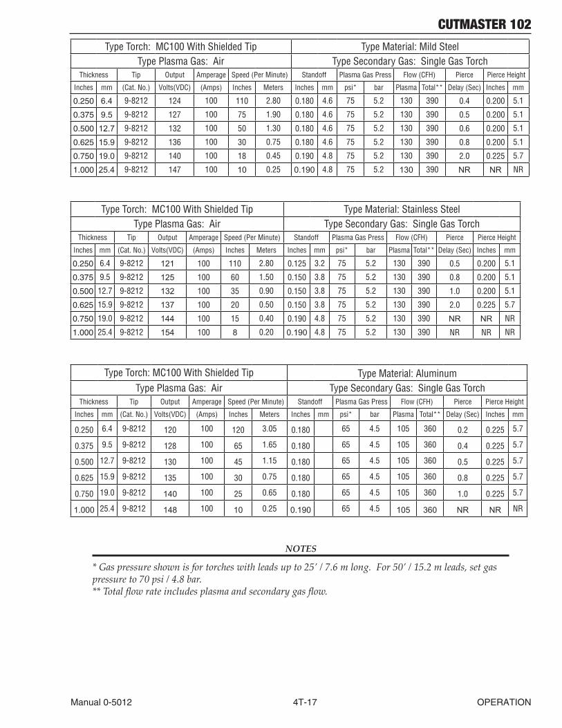
CUTMASTER 102
Manual 0-5012 4T-17 OPERATION
Type Torch: MC100 With Shielded Tip Type Material: Mild SteelType Plasma Gas: Air Type Secondary Gas: Single Gas Torch
Thickness Tip Output Amperage Speed(PerMinute) Standoff Plasma Gas Press Flow(CFH) Pierce PierceHeight
Inches mm (Cat.No.) Volts(VDC) (Amps) Inches Meters Inches mm psi* bar Plasma Total** Delay(Sec) Inches mm
0.250 6.4 9-8212 124 100 110 2.80 0.180 4.6 75 5.2 130 390 0.4 0.200 5.1
0.375 9.5 9-8212 127 100 75 1.90 0.180 4.6 75 5.2 130 390 0.5 0.200 5.1
0.500 12.7 9-8212 132 100 50 1.30 0.180 4.6 75 5.2 130 390 0.6 0.200 5.1
0.625 15.9 9-8212 136 100 30 0.75 0.180 4.6 75 5.2 130 390 0.8 0.200 5.1
0.750 19.0 9-8212 140 100 18 0.45 0.190 4.8 75 5.2 130 390 2.0 0.225 5.7
1.000 25.4 9-8212 147 100 10 0.25 0.190 4.8 75 5.2 130 390 NR NR NR
Type Torch: MC100 With Shielded Tip Type Material: Stainless SteelType Plasma Gas: Air Type Secondary Gas: Single Gas Torch
Thickness Tip Output Amperage Speed(PerMinute) Standoff Plasma Gas Press Flow(CFH) Pierce PierceHeight
Inches mm (Cat.No.) Volts(VDC) (Amps) Inches Meters Inches mm psi* bar Plasma Total** Delay(Sec) Inches mm
0.250 6.4 9-8212 121 100 110 2.80 0.125 3.2 75 5.2 130 390 0.5 0.200 5.1
0.375 9.5 9-8212 125 100 60 1.50 0.150 3.8 75 5.2 130 390 0.8 0.200 5.1
0.500 12.7 9-8212 132 100 35 0.90 0.150 3.8 75 5.2 130 390 1.0 0.200 5.1
0.625 15.9 9-8212 137 100 20 0.50 0.150 3.8 75 5.2 130 390 2.0 0.225 5.7
0.750 19.0 9-8212 144 100 15 0.40 0.190 4.8 75 5.2 130 390 NR NR NR
1.000 25.4 9-8212 154 100 8 0.20 0.190 4.8 75 5.2 130 390 NR NR NR
Type Torch: MC100 With Shielded Tip Type Material: AluminumType Plasma Gas: Air Type Secondary Gas: Single Gas Torch
Thickness Tip Output Amperage Speed(PerMinute) Standoff Plasma Gas Press Flow(CFH) Pierce PierceHeight
Inches mm (Cat.No.) Volts(VDC) (Amps) Inches Meters Inches mm psi* bar Plasma Total** Delay(Sec) Inches mm
0.250 6.4 9-8212 120 100 120 3.05 0.180 65 4.5 105 360 0.2 0.225 5.7
0.375 9.5 9-8212 128 100 65 1.65 0.180 65 4.5 105 360 0.4 0.225 5.7
0.500 12.7 9-8212 130 100 45 1.15 0.180 65 4.5 105 360 0.5 0.225 5.7
0.625 15.9 9-8212 135 100 30 0.75 0.180 65 4.5 105 360 0.8 0.225 5.7
0.750 19.0 9-8212 140 100 25 0.65 0.180 65 4.5 105 360 1.0 0.225 5.7
1.000 25.4 9-8212 148 100 10 0.25 0.190 65 4.5 105 360 NR NR NR
NOTES
* Gas pressure shown is for torches with leads up to 25’ / 7.6 m long. For 50’ / 15.2 m leads, set gas pressure to 70 psi / 4.8 bar. ** Total flow rate includes plasma and secondary gas flow.
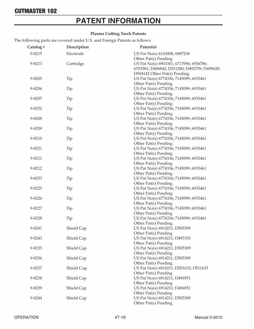
CUTMASTER 102
OPERATION 4T-18 Manual 0-5012
PATENT INFORMATION
Plasma Cutting Torch PatentsThe following parts are covered under U.S. and Foreign Patents as follows:
Catalog # Description Patent(s) 9-8215 Electrode US Pat No(s) 6163008; 6987238 Other Pat(s) Pending 9-8213 Cartridge US Pat No(s) 6903301; 6717096; 6936786; 6703581; D496842; D511280; D492709; D499620; D504142 Other Pat(s) Pending 9-8205 Tip US Pat No(s) 6774336; 7145099; 6933461 Other Pat(s) Pending 9-8206 Tip US Pat No(s) 6774336; 7145099; 6933461 Other Pat(s) Pending 9-8207 Tip US Pat No(s) 6774336; 7145099; 6933461 Other Pat(s) Pending 9-8252 Tip US Pat No(s) 6774336; 7145099; 6933461 Other Pat(s) Pending 9-8208 Tip US Pat No(s) 6774336; 7145099; 6933461 Other Pat(s) Pending 9-8209 Tip US Pat No(s) 6774336; 7145099; 6933461 Other Pat(s) Pending 9-8210 Tip US Pat No(s) 6774336; 7145099; 6933461 Other Pat(s) Pending 9-8231 Tip US Pat No(s) 6774336; 7145099; 6933461 Other Pat(s) Pending 9-8211 Tip US Pat No(s) 6774336; 7145099; 6933461 Other Pat(s) Pending 9-8212 Tip US Pat No(s) 6774336; 7145099; 6933461 Other Pat(s) Pending 9-8253 Tip US Pat No(s) 6774336; 7145099; 6933461 Other Pat(s) Pending 9-8225 Tip US Pat No(s) 6774336; 7145099; 6933461 Other Pat(s) Pending 9-8226 Tip US Pat No(s) 6774336; 7145099; 6933461 Other Pat(s) Pending 9-8227 Tip US Pat No(s) 6774336; 7145099; 6933461 Other Pat(s) Pending 9-8228 Tip US Pat No(s) 6774336; 7145099; 6933461 Other Pat(s) Pending 9-8241 Shield Cap US Pat No(s) 6914211; D505309 Other Pat(s) Pending 9-8243 Shield Cap US Pat No(s) 6914211; D493183 Other Pat(s) Pending 9-8235 Shield Cap US Pat No(s) 6914211; D505309 Other Pat(s) Pending 9-8236 Shield Cap US Pat No(s) 6914211; D505309 Other Pat(s) Pending 9-8237 Shield Cup US Pat No(s) 6914211; D501632; D511633 Other Pat(s) Pending 9-8238 Shield Cap US Pat No(s) 6914211; D496951 Other Pat(s) Pending 9-8239 Shield Cap US Pat No(s) 6914211; D496951 Other Pat(s) Pending 9-8244 Shield Cap US Pat No(s) 6914211; D505309 Other Pat(s) Pending

CUTMASTER 102
Manual 0-5012 4T-19 OPERATION
Catalog # Description Patent(s) 9-8245 Shield Cap US Pat No(s) 6914211; D496951 Other Pat(s) Pending
The following parts are also licensed under U.S. Patent No. 5,120,930 and 5,132,512:
Catalog # Description9-8235 Shield Cap9-8236 Shield Cap9-8237 Shield Cup9-8238 Shield Cap9-8239 Shield Cap9-8244 Shield Cap9-8245 Shield Cap

CUTMASTER 102
OPERATION 4T-20 Manual 0-5012
This Page Intentionally Blank

CUTMASTER 102
Manual 0-5012 5-1 SERVICE
SECTION 5 SYSTEM: SERVICE
5.01 General Maintenance
Warning!Disconnect input power before maintaining.
Each Use
Visual check oftorch tip and electrode
Weekly
Visually inspect the torch body tip, electrode, start cartridge and shield cup
Visually inspect thecables and leads.Replace as needed
3 Months
Cleanexteriorof power supply
6 Months
Replace all broken parts
Visually check and Carefully clean the interior
Maintain more oftenif used under severeconditions
Art # A-07938_AB
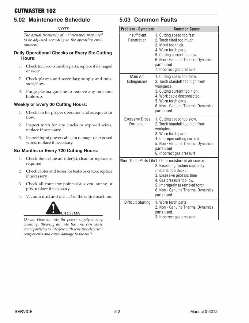
CUTMASTER 102
SERVICE 5-2 Manual 0-5012
5.02 Maintenance Schedule
NOTEThe actual frequency of maintenance may need to be adjusted according to the operating envi-ronment.
Daily Operational Checks or Every Six Cutting Hours:
1. Check torch consumable parts, replace if damaged or worn.
2. Check plasma and secondary supply and pres-sure/flow.
3. Purge plasma gas line to remove any moisture build-up.
Weekly or Every 30 Cutting Hours:
1. Check fan for proper operation and adequate air flow.
2. Inspect torch for any cracks or exposed wires, replace if necessary.
3. Inspect input power cable for damage or exposed wires, replace if necessary.
Six Months or Every 720 Cutting Hours:
1. Check the in-line air filter(s), clean or replace as required
2. Check cables and hoses for leaks or cracks, replace if necessary.
3. Check all contactor points for severe arcing or pits, replace if necessary.
4. Vacuum dust and dirt out of the entire machine.
CAUTIONDo not blow air into the power supply during cleaning. Blowing air into the unit can cause metal particles to interfere with sensitive electrical components and cause damage to the unit.
5.03 Common Faults
Problem - Symptom Common CauseInsufficientPenetration
1. Cutting speed too fast. 2. Torch tilted too much. 3. Metal too thick. 4. Worn torch parts 5. Cutting current too low. 6. Non - Genuine Thermal Dynamics parts used 7. Incorrect gas pressure
Main Arc Extinguishes
1. Cutting speed too slow. 2. Torch standoff too high from workpiece. 3. Cutting current too high. 4. Work cable disconnected. 5. Worn torch parts. 6. Non - Genuine Thermal Dynamics parts used
Excessive Dross Formation
1. Cutting speed too slow. 2. Torch standoff too high from workpiece. 3. Worn torch parts. 4. Improper cutting current. 5. Non - Genuine Thermal Dynamics parts used 6. Incorrect gas pressure
Short Torch Parts Life1. Oil or moisture in air source. 2. Exceeding system capability (materialtoothick). 3. Excessive pilot arc time 4. Gas pressure too low. 5. Improperly assembled torch. 6. Non - Genuine Thermal Dynamics parts used
DifficultStarting 1. Worn torch parts. 2. Non - Genuine Thermal Dynamics parts used. 3. Incorrect gas pressure.
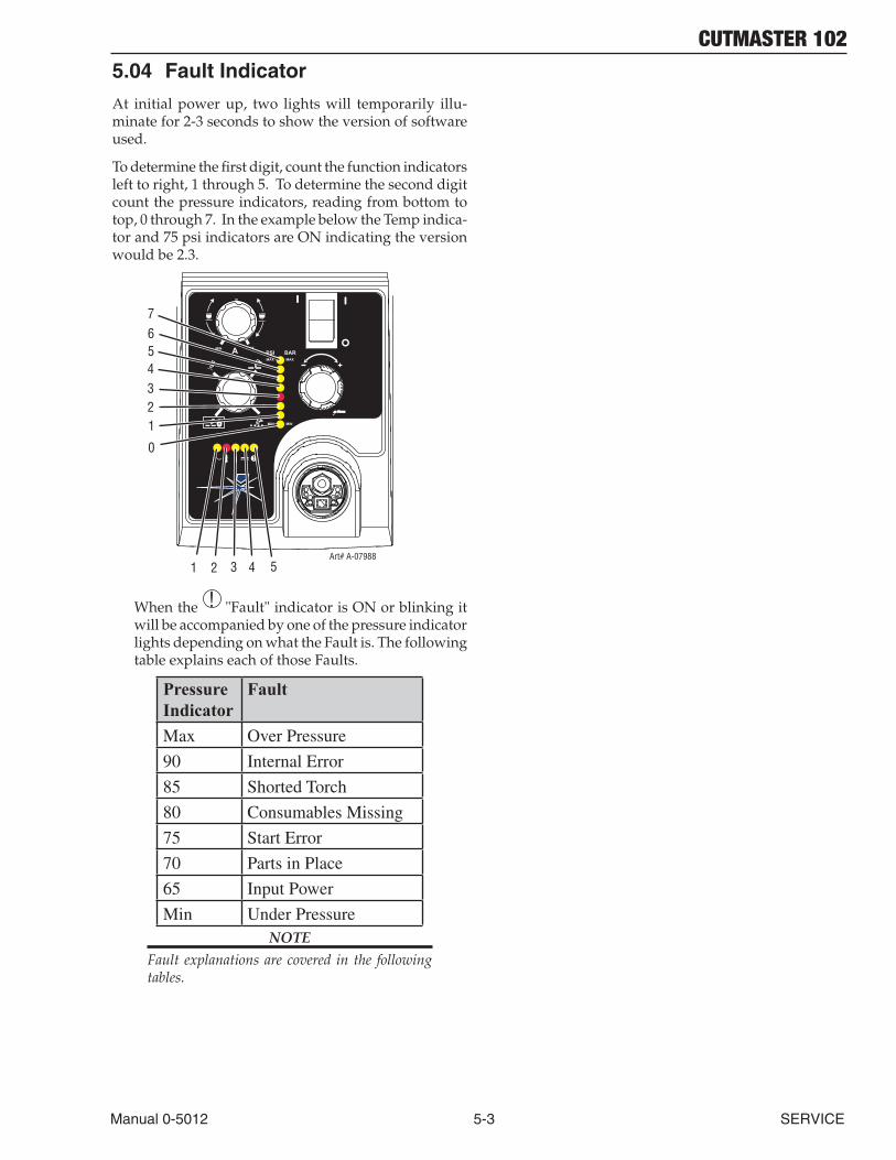
CUTMASTER 102
Manual 0-5012 5-3 SERVICE
5.04 Fault Indicator
At initial power up, two lights will temporarily illu-minate for 2-3 seconds to show the version of software used.
To determine the first digit, count the function indicators left to right, 1 through 5. To determine the second digit count the pressure indicators, reading from bottom to top, 0 through 7. In the example below the Temp indica-tor and 75 psi indicators are ON indicating the version would be 2.3.
A+
PSI BARMAX MAX
MIN MIN
!
1 2 3 4Art# A-07988
MIN MAX
0
1234567
5
When the ! "Fault" indicator is ON or blinking it will be accompanied by one of the pressure indicator lights depending on what the Fault is. The following table explains each of those Faults.
Pressure Indicator
Fault
Max Over Pressure
90 Internal Error
85 Shorted Torch
80 Consumables Missing
75 Start Error
70 Parts in Place
65 Input Power
Min Under PressureNOTE
Fault explanations are covered in the following tables.

CUTMASTER 102
SERVICE 5-4 Manual 0-5012
5.05 Basic Troubleshooting Guide
WARNING
There are extremely dangerous voltage and power levels present inside this unit. Do not attempt to diagnose or repair unless you have had training in power electronics measurement and troubleshooting techniques.
Problem - Symptom Possible Cause Recommended ActionON/OFFSwitchis ON but the A/C Indicator does not light
1. Primary power disconnect is in OFFposition.2. Primary fuses / breakers are blown or tripped.3.Unitsinternalfuseblown.
4.Faultycomponentsinunit.
1. Turn primary power disconnect switch to ON position.
2.a)Havequalifiedpersoncheckprimaryfuses/breakers. b)Connectunittoknowngoodprimarypowerreceptacle3.a)Replacefuse. b)Iffuseblowsagain,returntoauthorizedservicecenterforrepair or replacement.4. Return to authorized service center for repair or replacement.
Faultindicatorflashing,65PSIindicatorflashing
1.INPUTVOLTAGESELECTIONSWITCHsetforincorrectvoltage.2. Primary input voltage problem.
3.Faultycomponentsinunit.
1.SetINPUTVOLTAGESELECTIONSWITCHtomatchprimaryinput voltage.2.Havequalifiedpersoncheckprimaryvoltagetoinsureitmeetsunitrequirementsseesection2.05.3. Return to authorized service center for repair or replacement.
TEMPERATUREindicatorON.FAULTindicatorflashing.
1.Airflowthroughoraroundtheunit is obstructed.2. Duty cycle of the unit has been exceeded 3.Failedcomponentsinunit
1. Refer to clearance information – section 2.04
2. Allow unit to cool.
3. Return to authorized service center for repair or replacement.
GASLEDOFF,FAULTand MIN pressure indicatorsflashing.
1. Gas supply not connected to unit.2. Gas supply not turned ON. 3. Gas supply pressure too low.4.AIRPRESSURECONTROLregulator set too low. 5.Failedcomponentsinunit.
1. Connect gas supply to unit.
2. Turn gas supply ON.3. Set air supply inlet pressure to unit to 120 psi. 4. Adjust regulator to set air pressure - see section 4.02.
5. Return to authorized service center for repair or replacement.
FAULTand70PSIindicatorsflashing.
1. Shield Cup loose. 2. Torch not properly connected to power supply. 3. Problem in torch and leads PIP circuit.4.Failedcomponentsinunit.
1.Handtightentheshieldcupuntilitissnug.2. Insure torch ATC is securely fastened to unit.
3. Replace torch and leads or return to authorized service center for repair or replacement. 4. Return to authorized service center for repair or replacement.
FAULTand75PSIindicatorsflashing.
1. Start signal is active when ON/OFFSWITCHisturnedtoONposition.
2. Problem in the torch and leads switch circuit. 3.Failedcomponentsinunit.
1. Start can be active for one of the following: •Handtorchswitchheldclosed •Handpendantswitchheldclosed •CNCSTARTsignalisactivelow Release the START signal source 2. Replace torch and leads or return to authorized service center for repair or replacement. 3. Return to authorized service center for repair or replacement.
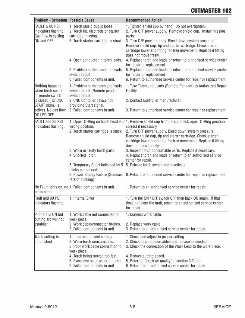
CUTMASTER 102
Manual 0-5012 5-5 SERVICE
Problem - Symptom Possible Cause Recommended ActionFAULT&80PSIindicatorsflashing.GasflowiscyclingONandOFF.
1. Torch shield cup is loose.2. Torch tip, electrode or starter cartridge missing. 3. Torch starter cartridge is stuck.
4. Open conductor in torch leads.
5. Problem in the torch and leads switch circuit. 6.Failedcomponentsinunit.
1. Tighten shield cup by hand. Do not overtighten. 2.TurnOFFpowersupply.Removeshieldcup.Installmissingparts.3.TurnOFFpowersupply.Bleeddownsystempressure.Remove shield cup, tip and starter cartridge. Check starter cartridgelowerendfittingforfreemovement.Replaceiffittingdoes not move freely.4. Replace torch and leads or return to authorized service center for repair or replacement. 5. Replace torch and leads or return to authorized service center for repair or replacement. 6. Return to authorized service center for repair or replacement.
Nothing happens when torch switch or remote switch isclosed(OrCNCSTART signal is active)Nogasflow,DCLEDOFF.
1. Problem in the torch and leads switchcircuit(Remotependantswitchcircuit).2. CNC Contoller device not providing Start signal.3.Failedcomponentsinunit.
1.TakeTorchandLeads(RemotePendant)toAuthorizedRepairFacility.
2. Contact Controller manufacturer.
3. Return to authorized service center for repair or replacement.
FAULTand85PSIindicatorsflashing.
1.UpperO-Ringontorchheadisinwrong position. 2. Torch starter cartridge is stuck. 3. Worn or faulty torch parts. 4. Shorted Torch. 5. Temporary Short indicated by 5 blinks per second. 6.PowerSupplyFailure(Standardrateofblinking)
1.Removeshieldcupfromtorch;checkupperO-Ringposition;correct if necessary. 2.TurnOFFpowersupply.Bleeddownsystempressure.Remove shield cup, tip and starter cartridge. Check starter cartridgelowerendfittingforfreemovement.Replaceiffittingdoes not move freely. 3. Inspect torch consumable parts. Replace if necessary. 4. Replace torch and leads or return to an authorized service center for repair. 5. Release torch switch and reactivate. 6. Return to authorized service center for repair or replacement.
NoFaultlightson,noarc in torch.
1.Failedcomponentsinunit. 1. Return to an authorized service center for repair.
Faultand90PSIindicatorsflashing
1. Internal Error 1.TurntheON/OFFswitchOFFthenbackONagain.Ifthatdoes not clear the fault, return to an authorized service center for repair.
Pilot arc is ON but cutting arc will not establish
1. Work cable not connected to work piece.2. Work cable/connector broken. 3.Failedcomponentsinunit.
1. Connect work cable.
2. Replace work cable.3. Return to an authorized service center for repair.
Torch cutting is diminished
1. Incorrect current setting. 2. Worn torch consumables.3. Poor work cable connection to work piece. 4. Torch being moved too fast.5. Excessive oil or water in torch. 6.Failedcomponentsinunit.
1. Check and adjust to proper setting.2. Check torch consumables and replace as needed. 3. Check the connection of the Work Lead to the work piece.
4. Reduce cutting speed. 5.Referto"Checkairquality"insection3Torch.6. Return to an authorized service center for repair.
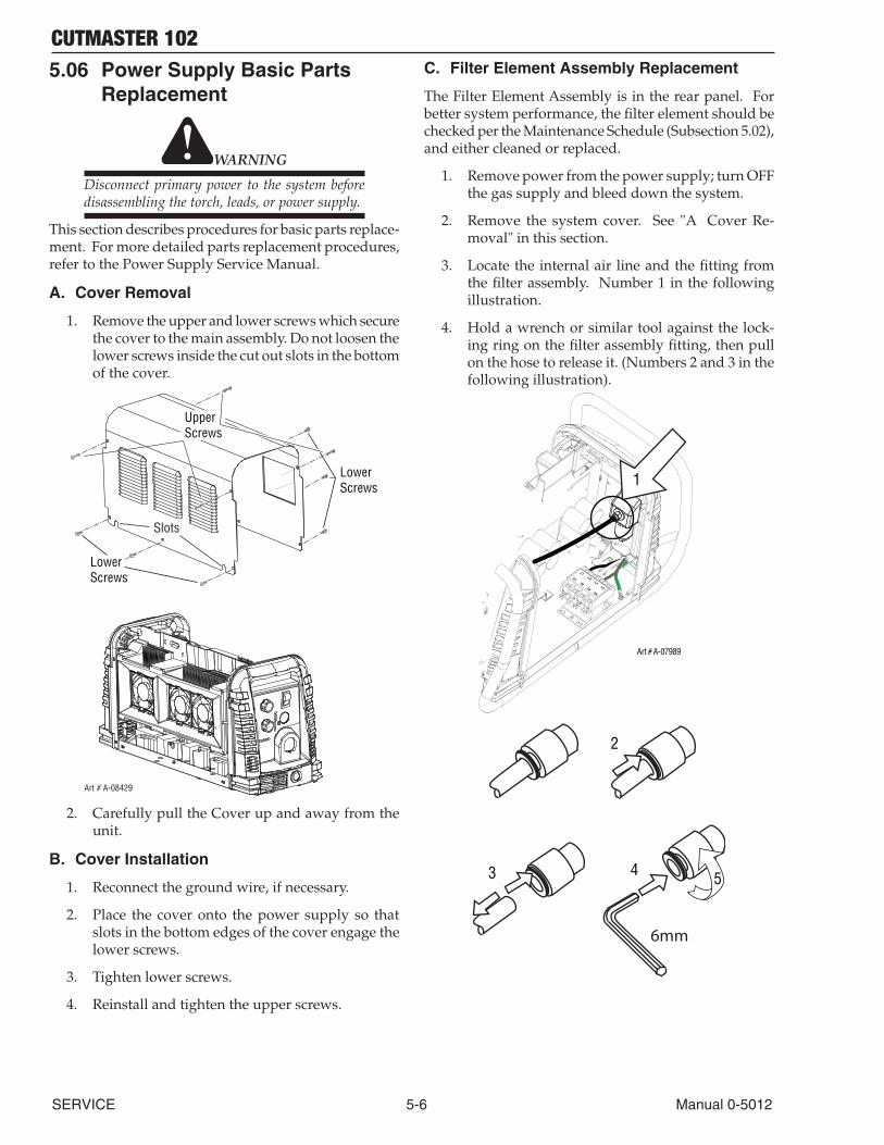
CUTMASTER 102
SERVICE 5-6 Manual 0-5012
5.06 Power Supply Basic Parts Replacement
WARNING
Disconnect primary power to the system before disassembling the torch, leads, or power supply.
This section describes procedures for basic parts replace-ment. For more detailed parts replacement procedures, refer to the Power Supply Service Manual.
A. Cover Removal
1. Remove the upper and lower screws which secure the cover to the main assembly. Do not loosen the lower screws inside the cut out slots in the bottom of the cover.
Art # A-08429
Lower Screws
Lower Screws
Slots
UpperScrews
2. Carefully pull the Cover up and away from the unit.
B. Cover Installation
1. Reconnect the ground wire, if necessary.
2. Place the cover onto the power supply so that slots in the bottom edges of the cover engage the lower screws.
3. Tighten lower screws.
4. Reinstall and tighten the upper screws.
C. Filter Element Assembly Replacement
The Filter Element Assembly is in the rear panel. For better system performance, the filter element should be checked per the Maintenance Schedule (Subsection 5.02), and either cleaned or replaced.
1. Remove power from the power supply; turn OFF the gas supply and bleed down the system.
2. Remove the system cover. See "A Cover Re-moval" in this section.
3. Locate the internal air line and the fitting from the filter assembly. Number 1 in the following illustration.
4. Hold a wrench or similar tool against the lock-ing ring on the filter assembly fitting, then pull on the hose to release it. (Numbers 2 and 3 in the following illustration).
Art # A-07989
1
2
3 4 5
6mm
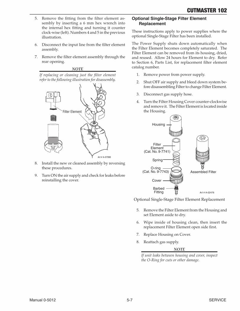
CUTMASTER 102
Manual 0-5012 5-7 SERVICE
5. Remove the fitting from the filter element as-sembly by inserting a 6 mm hex wrench into the internal hex fitting and turning it counter clock-wise (left). Numbers 4 and 5 in the previous illustration.
6. Disconnect the input line from the filter element assembly.
7. Remove the filter element assembly through the rear opening.
NOTEIf replacing or cleaning just the filter element refer to the following illustration for disassembly.
Art # A-07990
Filter Element
8. Install the new or cleaned assembly by reversing these procedures.
9. Turn ON the air supply and check for leaks before reinstalling the cover.
Optional Single-Stage Filter Element Replacement
These instructions apply to power supplies where the optional Single-Stage Filter has been installed.
The Power Supply shuts down automatically when the Filter Element becomes completely saturated. The Filter Element can be removed from its housing, dried, and reused. Allow 24 hours for Element to dry. Refer to Section 6, Parts List, for replacement filter element catalog number.
1. Remove power from power supply.
2. Shut OFF air supply and bleed down system be-fore disassembling Filter to change Filter Element.
3. Disconnect gas supply hose.
4. Turn the Filter Housing Cover counter-clockwise and remove it. The Filter Element is located inside the Housing.
Art # A-02476
FilterElement
(Cat. No. 9-7741)
Housing
Cover
BarbedFitting
Spring
Assembled FilterO-ring
(Cat. No. 9-7743)
Optional Single-Stage Filter Element Replacement
5. Remove the Filter Element from the Housing and set Element aside to dry.
6. Wipe inside of housing clean, then insert the replacement Filter Element open side first.
7. Replace Housing on Cover.
8. Reattach gas supply.
NOTEIf unit leaks between housing and cover, inspect the O-Ring for cuts or other damage.
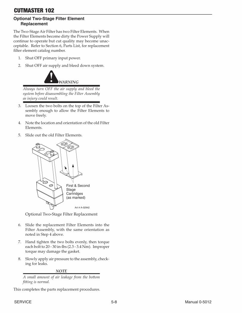
CUTMASTER 102
SERVICE 5-8 Manual 0-5012
Optional Two-Stage Filter Element Replacement
The Two-Stage Air Filter has two Filter Elements. When the Filter Elements become dirty the Power Supply will continue to operate but cut quality may become unac-ceptable. Refer to Section 6, Parts List, for replacement filter element catalog number.
1. Shut OFF primary input power.
2. Shut OFF air supply and bleed down system.
WARNING
Always turn OFF the air supply and bleed the system before disassembling the Filter Assembly as injury could result.
3. Loosen the two bolts on the top of the Filter As-sembly enough to allow the Filter Elements to move freely.
4. Note the location and orientation of the old Filter Elements.
5. Slide out the old Filter Elements.
First & Second StageCartridges (as marked)
Art # A-02942
Optional Two-Stage Filter Replacement
6. Slide the replacement Filter Elements into the Filter Assembly, with the same orientation as noted in Step 4 above.
7. Hand tighten the two bolts evenly, then torque each bolt to 20 - 30 in-lbs (2.3 - 3.4 Nm). Improper torque may damage the gasket.
8. Slowly apply air pressure to the assembly, check-ing for leaks.
NOTEA small amount of air leakage from the bottom fitting is normal.
This completes the parts replacement procedures.
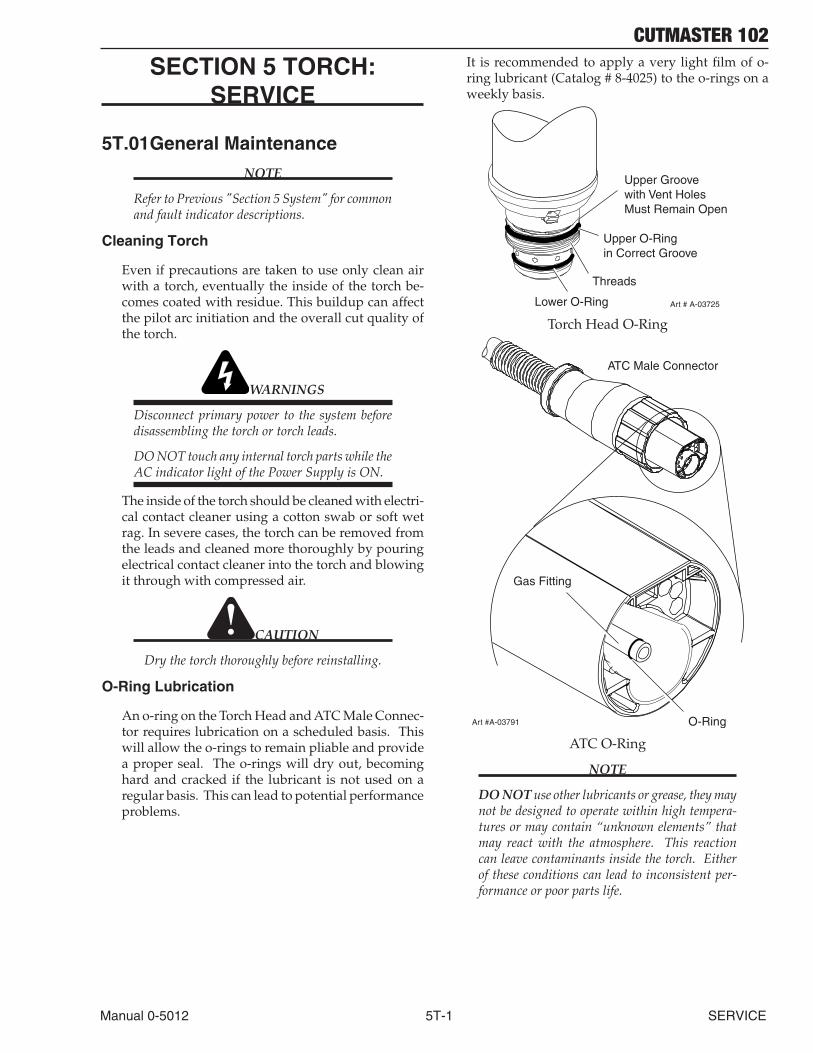
CUTMASTER 102
Manual 0-5012 5T-1 SERVICE
SECTION 5 TORCH: SERVICE
5T.01 General Maintenance
NOTE
Refer to Previous "Section 5 System" for common and fault indicator descriptions.
Cleaning Torch
Even if precautions are taken to use only clean air with a torch, eventually the inside of the torch be-comes coated with residue. This buildup can affect the pilot arc initiation and the overall cut quality of the torch.
WARNINGS
Disconnect primary power to the system before disassembling the torch or torch leads.
DO NOT touch any internal torch parts while the AC indicator light of the Power Supply is ON.
The inside of the torch should be cleaned with electri-cal contact cleaner using a cotton swab or soft wet rag. In severe cases, the torch can be removed from the leads and cleaned more thoroughly by pouring electrical contact cleaner into the torch and blowing it through with compressed air.
CAUTION
Dry the torch thoroughly before reinstalling.
O-Ring Lubrication
An o-ring on the Torch Head and ATC Male Connec-tor requires lubrication on a scheduled basis. This will allow the o-rings to remain pliable and provide a proper seal. The o-rings will dry out, becoming hard and cracked if the lubricant is not used on a regular basis. This can lead to potential performance problems.
It is recommended to apply a very light film of o-ring lubricant (Catalog # 8-4025) to the o-rings on a weekly basis.
Upper Groovewith Vent HolesMust Remain Open
Threads
Upper O-Ringin Correct Groove
Lower O-Ring Art # A-03725
Torch Head O-Ring
ATC Male Connector
Art #A-03791
Gas Fitting
O-Ring
ATC O-Ring
NOTE
DO NOT use other lubricants or grease, they may not be designed to operate within high tempera-tures or may contain “unknown elements” that may react with the atmosphere. This reaction can leave contaminants inside the torch. Either of these conditions can lead to inconsistent per-formance or poor parts life.
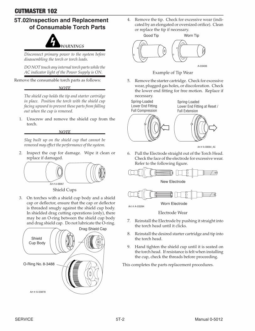
CUTMASTER 102
SERVICE 5T-2 Manual 0-5012
5T.02 Inspection and Replacement of Consumable Torch Parts
WARNINGS
Disconnect primary power to the system before disassembling the torch or torch leads.
DO NOT touch any internal torch parts while the AC indicator light of the Power Supply is ON.
Remove the consumable torch parts as follows:
NOTE
The shield cup holds the tip and starter cartridge in place. Position the torch with the shield cup facing upward to prevent these parts from falling out when the cup is removed.
1. Unscrew and remove the shield cup from the torch.
NOTE
Slag built up on the shield cup that cannot be removed may effect the performance of the system.
2. Inspect the cup for damage. Wipe it clean or replace if damaged.
Art # A-08067
Shield Cups
3. On torches with a shield cup body and a shield cap or deflector, ensure that the cap or deflector is threaded snugly against the shield cup body. In shielded drag cutting operations (only), there may be an O-ring between the shield cup body and drag shield cap. Do not lubricate the O-ring.
Drag Shield Cap
Shield Cup Body
O-Ring No. 8-3488
Art # A-03878
4. Remove the tip. Check for excessive wear (indi-cated by an elongated or oversized orifice). Clean or replace the tip if necessary.
Good Tip Worn Tip
A-03406
Example of Tip Wear
5. Remove the starter cartridge. Check for excessive wear, plugged gas holes, or discoloration. Check the lower end fitting for free motion. Replace if necessary.
Art # A-08064_AC
Spring-Loaded Lower End FittingFull Compression
Spring-Loaded Lower End Fitting at Reset /Full Extension
6. Pull the Electrode straight out of the Torch Head. Check the face of the electrode for excessive wear. Refer to the following figure.
Worn Electrode
New Electrode
Art # A-03284
Electrode Wear
7. Reinstall the Electrode by pushing it straight into the torch head until it clicks.
8. Reinstall the desired starter cartridge and tip into the torch head.
9. Hand tighten the shield cup until it is seated on the torch head. If resistance is felt when installing the cup, check the threads before proceeding.
This completes the parts replacement procedures.
CUTMASTER 102
Manual 0-5012 6-1 PARTS LIST
SECTION 6: PARTS LISTS
6.01 Introduction
A. Parts List Breakdown
The parts list provide a breakdown of all replaceable components. The parts lists are arranged as follows:
Section "6.03 Power Supply Replacement"
Section "6.04 Replacement Power Supply Parts"
Section "6.05 Options and Accessories"
Section "6.06 Replacement Parts for Hand Torch"
Section "6.07 Replacement Parts - for Machine Torches with Unshielded Leads"
Section "6.08 Torch Consumable Parts (MC100)"
NOTE
Parts listed without item numbers are not shown, but may be ordered by the catalog number shown.
B. Returns
If a product must be returned for service, contact your distributor. Materials returned without proper authorization will not be accepted.
6.02 Ordering Information
Order replacement parts by catalog number and complete description of the part or assembly, as listed in the parts list for each type item. Also include the model and serial number of the power supply. Address all inquiries to your authorized distributor.
6.03 Power Supply Replacement
The following items are included with the replacement power supply: work cable & clamp, input power cable, gas pressure regulator / filter, and operating manual.
Qty Description Catalog # 1 CutMaster 102 Power Supply 208/230 - 460VAC, Single or 3 Phase, 60Hz, with 208/230V single phase input power cable and plug 3-1330-1 with 460V single phase input power cable 3-1330-2

CUTMASTER 102
PARTS LIST 6-2 Manual 0-5012
6.04 Replacement Power Supply Parts
Qty Description Catalog # 1 Regulator 9-0115 1 Filter Assembly Replacement Element 9-0116 1 Input Power Cord for 208 / 230 V Power Supply 9-8596 1 Input Power Cord for 400 V Power Supply 9-8562 1 Input Power Cord for 460 V Power Supply 9-8563
6.05 Options and Accessories
Qty Description Catalog # 1 Single - Stage Filter Kit (includes Filter & Hose) 7-7507 1 Replacement Filter Body 9-7740 1 Replacement Filter Hose (not shown) 9-7742 2 Replacement Filter Element 9-7741 1 Extended Work Cable ( 50 ft / 15.2 m ) with Clamp 9-8529 1 Multi - Purpose Cart 7-8888 1 Automation Interface Kit 9-8310 1 25' / 7.6 m CNC Cable for Automation Interface Kit 9-8312 1 50' /15.2 m CNC Cable for Automation Interface Kit 9-8313 1 Nylon Dust Cover 9-7071
Art # A-02476
FilterElement
(Cat. No. 9-7741)
Housing
Cover
BarbedFitting
Spring
Assembled FilterO-ring
(Cat. No. 9-7743)
Optional Single - Stage Filter Kit
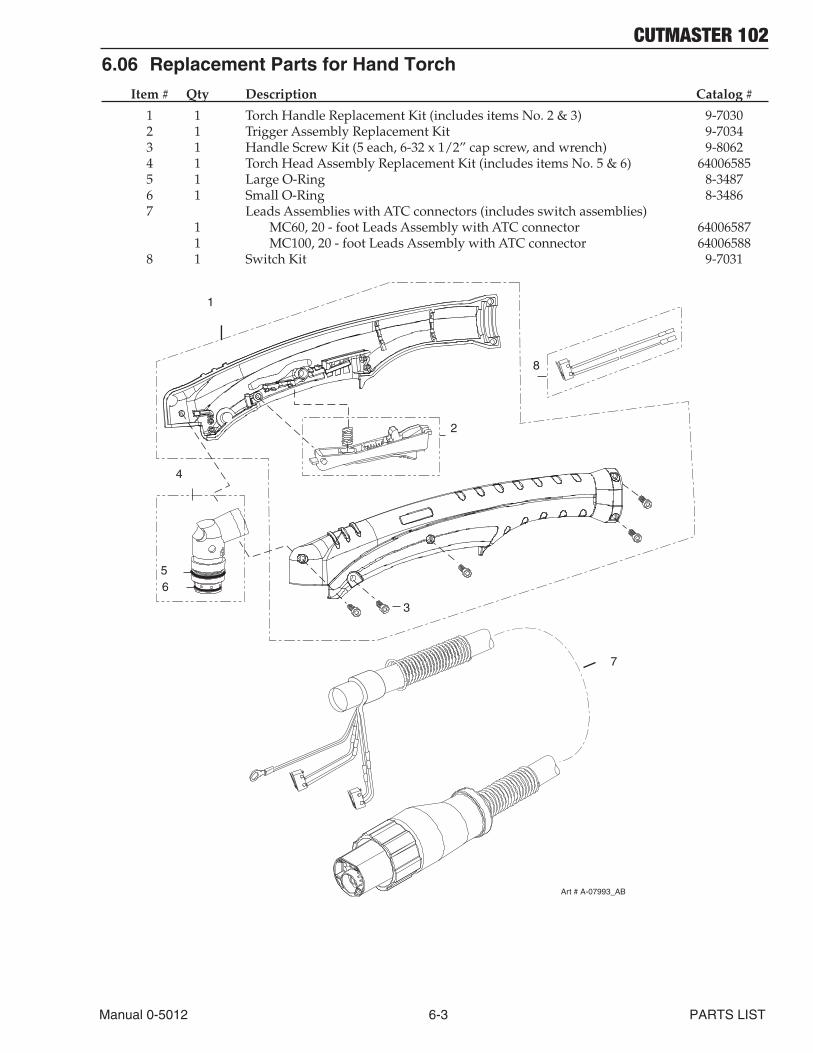
CUTMASTER 102
Manual 0-5012 6-3 PARTS LIST
6.06 Replacement Parts for Hand Torch
Item # Qty Description Catalog # 1 1 Torch Handle Replacement Kit (includes items No. 2 & 3) 9-7030 2 1 Trigger Assembly Replacement Kit 9-7034 3 1 Handle Screw Kit (5 each, 6-32 x 1/2” cap screw, and wrench) 9-8062 4 1 Torch Head Assembly Replacement Kit (includes items No. 5 & 6) 64006585 5 1 Large O-Ring 8-3487 6 1 Small O-Ring 8-3486 7 Leads Assemblies with ATC connectors (includes switch assemblies) 1 MC60, 20 - foot Leads Assembly with ATC connector 64006587 1 MC100, 20 - foot Leads Assembly with ATC connector 64006588 8 1 Switch Kit 9-7031
7
56
3
4
2
Art # A-07993_AB
1
8

CUTMASTER 102
PARTS LIST 6-4 Manual 0-5012
6.07 Replacement Parts - for Machine Torches with Unshielded Leads
Item No. Qty Description Catalog No. 1 1 Torch Head Assembly without leads (includes items 2, 3, and 14) 64006586 2 1 Large O-Ring 8-3487 3 1 Small O-Ring 8-3486 4 1 PIP Switch Kit 9-7036 5 Unshielded Automated Leads Assemblies with ATC connectors 1 5 - foot / 1.5 m Leads Assembly with ATC connector 4-7850 1 10 - foot / 3.05 m Leads Assembly with ATC connector 4-7851 1 25 - foot / 7.6 m Leads Assembly with ATC connector 4-7852 1 50 - foot / 15.2 m Leads Assembly with ATC connector 4-7853 6 Unshielded Mechanized Leads Assemblies with ATC connectors 1 5 - foot / 1.5 m Leads Assembly with ATC connector 4-7842 1 10 - foot / 3.05 m Leads Assembly with ATC connector 4-7843 1 25 - foot / 7.6 m Leads Assembly with ATC connector 4-7844 1 50 - foot / 15.2 m Leads Assembly with ATC connector 4-7845 7 1 11” / 279 mm Rack 9-7041 8 1 11” / 279 mm Mounting Tube 9-7043 9 1 End Cap Assembly 9-7044 10 2 Body, Mounting, Pinch Block 9-4513 11 1 Pin, Mounting, Pinch Block 9-4521 12 1 Torch Holder Sleeve 7-2896 13 1 PIP Plunger and Return Spring Kit 9-7045 1 Pinion Assembly (Not shown) 7-2827
NOTE
* Does not include Control Cable Adapter or Through - Hole Protector.
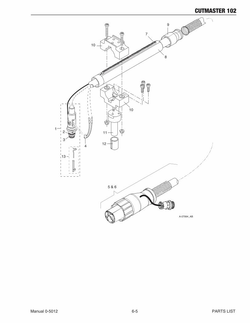
CUTMASTER 102
Manual 0-5012 6-5 PARTS LIST
A-07994_AB
1
4
2
3
5 & 6
7
8
9
10
12
11
10
13
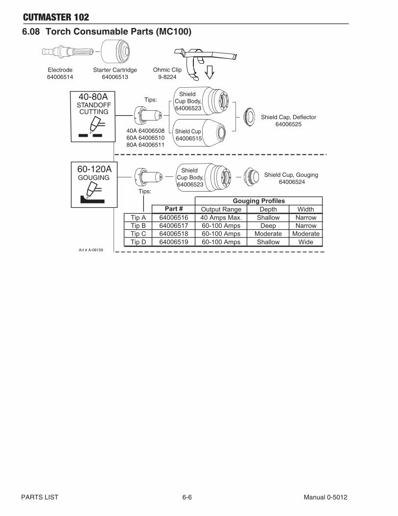
CUTMASTER 102
PARTS LIST 6-6 Manual 0-5012
6.08 Torch Consumable Parts (MC100)
Starter Cartridge64006513
Electrode64006514
Shield Cup, Gouging 64006524
Shield Cup Body,64006523
40-80A Tips:
Tips:
60-120AGOUGING
CUTTING
Shield Cup Body,64006523
Shield Cup 64006515
Art # A-08159
STANDOFF
Shield Cap, Deflector64006525
Ohmic Clip9-8224
Part # Output Range Depth WidthTip A 64006516 40 Amps Max. Shallow NarrowTip B 64006517 60-100 Amps Deep NarrowTip C 64006518 60-100 Amps Moderate ModerateTip D 64006519 60-100 Amps Shallow Wide
Gouging Profiles
40A 6400650860A 6400651080A 64006511
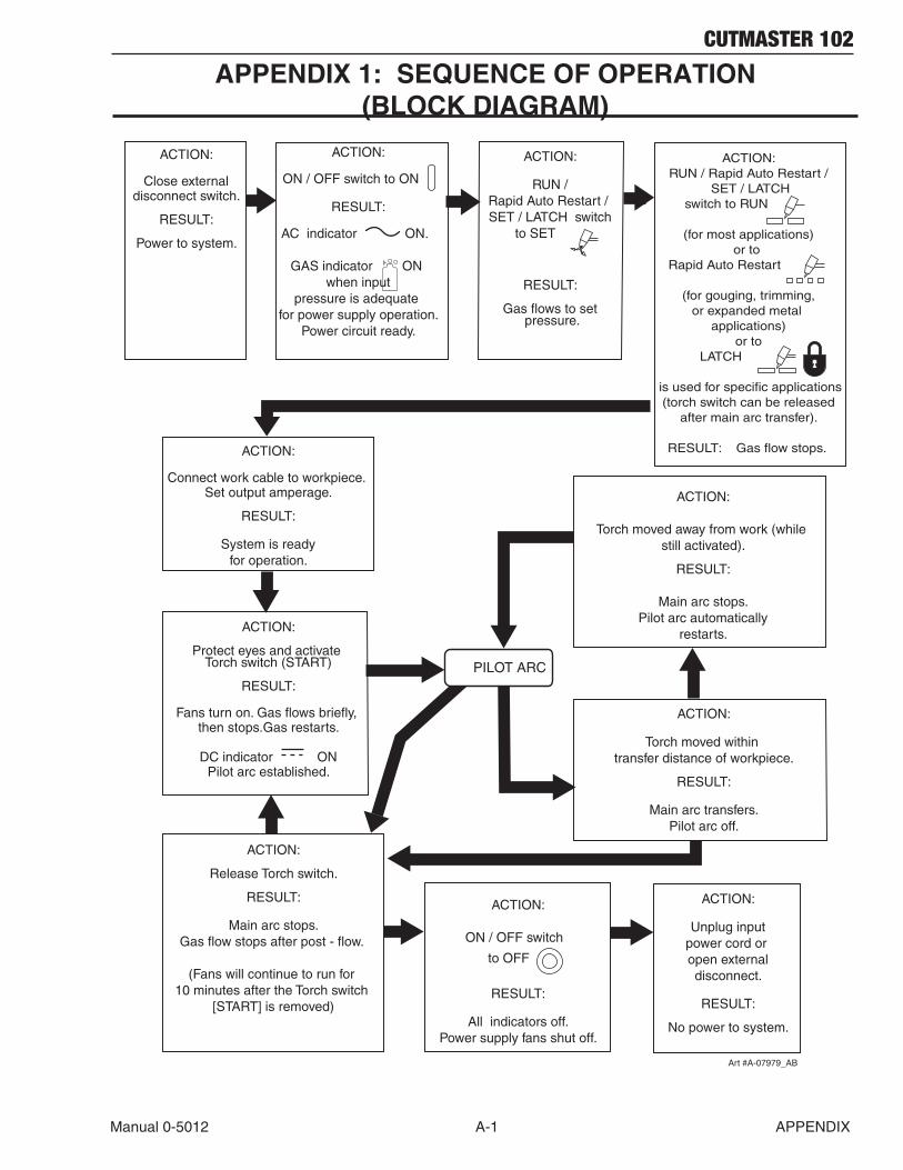
CUTMASTER 102
Manual 0-5012 A-1 APPENDIX
APPENDIX 1: SEQUENCE OF OPERATION (BLOCK DIAGRAM)
ACTION:
ON / OFF switch to ON
RESULT:
AC indicator ON.
GAS indicator ON when input
pressure is adequate for power supply operation.
Power circuit ready.
ACTION:
Protect eyes and activate Torch switch (START)
RESULT:
Fans turn on. Gas flows briefly, then stops.Gas restarts.
DC indicator ONPilot arc established.
ACTION:
Unplug inputpower cord or open externaldisconnect.
RESULT:
No power to system.
ACTION:
Connect work cable to workpiece. Set output amperage.
RESULT:
System is readyfor operation.
ACTION:
RUN / Rapid Auto Restart / SET / LATCH switch
to SET
RESULT:
Gas flows to set pressure.
ACTION:RUN / Rapid Auto Restart /
SET / LATCHswitch to RUN
(for most applications) or to
Rapid Auto Restart
(for gouging, trimming,or expanded metal
applications)or to
LATCH
is used for specific applications (torch switch can be released
after main arc transfer).
RESULT: Gas flow stops.
ACTION:
Release Torch switch.
RESULT:
Main arc stops.Gas flow stops after post - flow.
(Fans will continue to run for 10 minutes after the Torch switch
[START] is removed)
ACTION:
ON / OFF switch
to OFF
RESULT:
All indicators off.Power supply fans shut off.
ACTION:
Close externaldisconnect switch.
RESULT:
Power to system.
ACTION:
Torch moved within transfer distance of workpiece.
RESULT:
Main arc transfers.Pilot arc off.
PILOT ARC
ACTION:
Torch moved away from work (while still activated).
RESULT:
Main arc stops.Pilot arc automatically
restarts.
Art #A-07979_AB
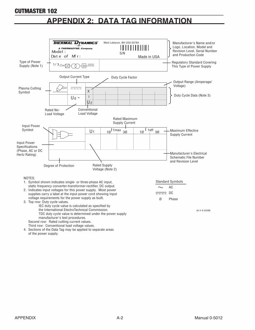
CUTMASTER 102
APPENDIX A-2 Manual 0-5012
1/ 3 ff
12
West Lebanon, NH USA 03784
Made in USAModel :
U1 1max 1effI I
U2
3Ø 3Ø1Ø1Ø
S/N
U0 =
X
Standard Symbols
Ø
AC
DC
Phase
NOTES:1. Symbol shown indicates single- or three-phase AC input, static frequency converter-transformer-rectifier, DC output.2. Indicates input voltages for this power supply. Most power supplies carry a label at the input power cord showing input voltage requirements for the power supply as built. 3. Top row: Duty cycle values. IEC duty cycle value is calculated as specified by the International ElectroTechnical Commission. TDC duty cycle value is determined under the power supply manufacturer's test procedures. Second row: Rated cutting current values. Third row: Conventional load voltage values.4. Sections of the Data Tag may be applied to separate areas of the power supply.
I
Art # A-03288
Dat e of Mf r :
Output Range (Amperage/Voltage)
Type of PowerSupply (Note 1)
Output Current Type
Rated No-Load Voltage
Plasma Cutting Symbol
Manufacturer's Name and/orLogo, Location, Model andRevision Level, Serial Number and Production Code
ConventionalLoad Voltage
Regulatory Standard CoveringThis Type of Power Supply
Duty Cycle Data (Note 3)
Duty Cycle Factor
Input PowerSpecifications (Phase, AC or DCHertz Rating)
Input PowerSymbol
Rated Supply Voltage (Note 2)
Rated MaximumSupply Current
Maximum Effective Supply Current
Degree of Protection
Manufacturer's ElectricalSchematic File Numberand Revision Level
APPENDIX 2: DATA TAG INFORMATION
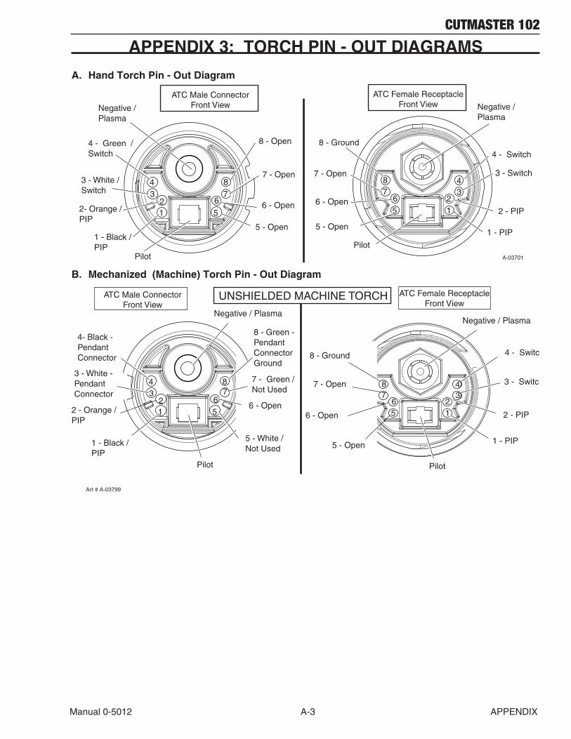
CUTMASTER 102
Manual 0-5012 A-3 APPENDIX
APPENDIX 3: TORCH PIN - OUT DIAGRAMS
A. Hand Torch Pin - Out Diagram
12
34
56
78
5
678
12
34
ATC Female ReceptacleFront View
PilotPilot
6 - Open
7 - Open
8 - Open
5 - Open
Negative / Plasma
6 - Open
7 - Open
5 - Open
2 - PIP
3 - Switch
4 - Switch
1 - PIP
4 - Green / Switch
2- Orange /PIP
3 - White / Switch
1 - Black /PIP
Negative / Plasma
8 - Ground
ATC Male ConnectorFront View
A-03701
B. Mechanized (Machine) Torch Pin - Out Diagram
ATC Female ReceptacleFront View
ATC Male ConnectorFront View
Negative / Plasma
3 - White - PendantConnector
4- Black - PendantConnector
2 - Orange /PIP
1 - Black /PIP
Pilot
2 - PIP
1 - PIP
6 - Open
7 - Open
5 - Open
8 - Ground
8 - Green - Pendant Connector Ground
5 - White /Not Used
7 - Green /Not Used
6 - Open
UNSHIELDED MACHINE TORCH
3 - Switch
4 - Switch
Art # A-03799
Negative / Plasma
Pilot
12
34
56
78
5
6
8
12
34
7
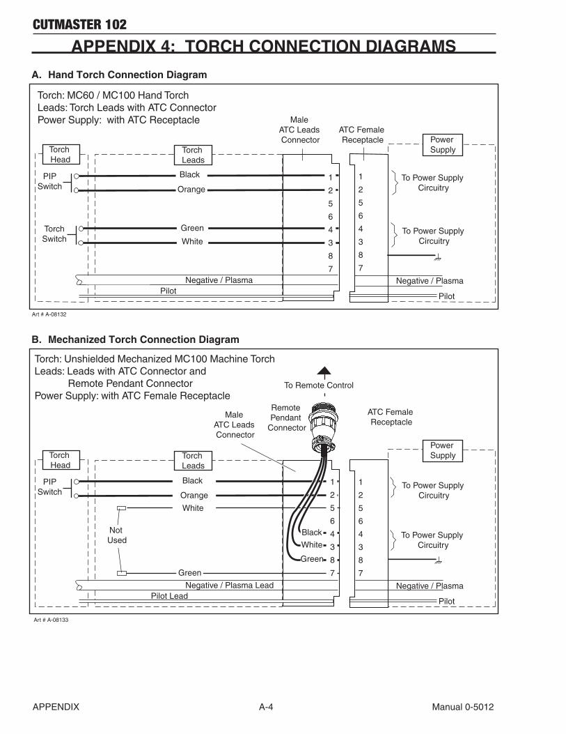
CUTMASTER 102
APPENDIX A-4 Manual 0-5012
APPENDIX 4: TORCH CONNECTION DIAGRAMS
A. Hand Torch Connection Diagram
Torch: MC60 / MC100 Hand TorchLeads: Torch Leads with ATC ConnectorPower Supply: with ATC Receptacle
Pilot
Negative / Plasma
Power Supply
PIPSwitch
Male ATC Leads Connector
ATC Female Receptacle
Pilot Negative / Plasma
Black
Orange
Torch Leads
Torch Head
To Power Supply Circuitry
Art # A-08132
1
2
5
6
4
3
8
7
1
2
5
6
4
3
8
7
TorchSwitch
Green
WhiteTo Power Supply
Circuitry
B. Mechanized Torch Connection Diagram
Torch: Unshielded Mechanized MC100 Machine Torch Leads: Leads with ATC Connector and Remote Pendant ConnectorPower Supply: with ATC Female Receptacle
Pilot
Negative / Plasma
Power Supply
To Remote Control
Remote Pendant
Connector
PIPSwitch
Not Used
Male ATC Leads Connector
ATC Female Receptacle
Pilot LeadNegative / Plasma Lead
Torch Leads
Torch Head
Art # A-08133
1
2
5
6
4
3
8
7
To Power Supply Circuitry
Green
To Power Supply Circuitry
1
2
5
6
4
3
8
7
Black
White
Green
Black
Orange
White

CUTMASTER 102
Manual 0-5012 A-5 APPENDIX
This Page Intentionally Blank

CUTMASTER 102
APPENDIX A-6 Manual 0-5012
APPENDIX 5: SYSTEM SCHEMATIC, 208/460V UNITS
5
5
4
4
3
3
2
2
1
1
D D
C C
B B
A A
+12VDC
+12VDC+12VDC
+12VDC
+12VDC
+12VDC
+12VDC
24VAC
+5VDC
+12VDC
+12VDC
+12VDC
DWG No:
Sheetof
SupersedesScale
Date:
Drawn: References
DateByRevisionsRev PCB No:Assy No:
Information Proprietary to THERMAL DYNAMICS CORPORATION.Not For Release, Reproduction, or Distribution without Written Consent.
NOTE:Unless Otherwise Specified, Resistors are in Ohms 1/4W 5%.Capacitors are in Microfarads (UF) Chk: App:
TITLE:Last Modified:
SizeSCHEMATIC,42X1315Monday, November 03, 2008
1 1
INDUSTRIAL PARK No. 2WEST LEBANON, NH 03784603-298-5711
230/460 VAC CUTMASTER 102 & 152
THERMAL DYNAMICS
DDWG No:
Sheetof
SupersedesScale
Date:
Drawn: References
DateByRevisionsRev PCB No:Assy No:
Information Proprietary to THERMAL DYNAMICS CORPORATION.Not For Release, Reproduction, or Distribution without Written Consent.
NOTE:Unless Otherwise Specified, Resistors are in Ohms 1/4W 5%.Capacitors are in Microfarads (UF) Chk: App:
TITLE:Last Modified:
SizeSCHEMATIC,42X1315Monday, November 03, 2008
1 1
INDUSTRIAL PARK No. 2WEST LEBANON, NH 03784603-298-5711
230/460 VAC CUTMASTER 102 & 152
THERMAL DYNAMICS
D
BUSS BARS/JUMPERS
D3
D1
L1
L2
L3
GND(5A @ 250VAC / 30VDC)
C D
B
A
_
Q2
_
B
CM 102 19X2478 / CAT# 9-0192CM 152 19X2545 / CAT# 9-0202
A
PCB5 CM 102 40 AMP PCB19X2417 / CAT# 9-0194
CM 152 50 AMP PCB19X2417 / CAT# 9-0203
PCB2
Q1
FAN
/FANFAN
/FAN
D2
D1
C D
CAPACITOR PCB
1 /OVERTEMP 2 /FAN_ON 3 /CSR 4 CUR_SET 5 MAIN_PCB_ID 6 COMMON
_
19X2369 / CAT# 9-0107
OVER PRESSUREINTERNAL ERRORSHORTED TORCHCONSUMABLES MISSINGSTART ERRORPARTS IN PLACEINPUT POWER UNDER PRESSURE
ERROR IND FAULT
PCB3
LATCH
SET
RUN
RAR
MAX 90 85 80 75 70 65MIN
TP1TP2TP3TP4TP5TP6TP7
LOGIC PCB
GND+12 VDC+5 VDC3.3 VDC0.v - 5.0 VDC / 0-100PSI1.8 VDCCURRENT DEMAND
TEST POINTS
FAN
TEMP CIRCUIT
Q2
808182
83
E64
E35
7879
-
+
*CM 102 C7 & C10 not installed
ATC CONNECTOR
GND1GND2+12V148V1I_DMD_1TIP_SEN
COMMONCOMMON+12 VDC SUPPLY+48 VDC SUPPLYCURRENT DEMANDTIP DRAG SENSE
TEST POINTS
CM152 ONLY
J2
_
J1
/460
INPUT VOLTAGE SELECTOR (Closed for 230VAC input)
460_IN
8
9
7A OK-TO-MOVE
PRIMARY POWER CONNECTIONS:
FOR 3 PH:REMOVE BUSS BARS/JUMPERS BETWEEN L1 TO L4 & L2 TO L3 CONNECT PRIMARY INPUT CABLE TO L1,L2,L3 & GND
FOR 1PH: INSTALL BUSS BARS/JUMPERS BETWEEN L1 TO L4 & L2 TO L3CONNECT PRIMARY INPUT CABLETO BUSS BARS (L1/L4) & (L2/L3)
*
*
L1
L2
L3
L4
T1
T2
T3
T4
/PIP
PCB1
+
+
+
+
Q1
24VAC RET
5
PRIMARYAC INPUT
6
/START
/SOLENOID
24VAC RETURN
24VAC SUPPLY
CM 102 19X2371 / CAT# 9-0108CM 152 19X2416 / CAT# 9-0125
MAIN PCB
7
0-100PSI / 0-4.5VDC
1TORCH
AUTOMATIONTORCH SOLENOID
PRESSURE TRANSDUCER
AIRINLET
FILTER
REGULATOR
SOLENOID VALVE ATC
GAS CONTROL
/OVERTEMP TEMP CIRCUIT
/OVERTEMP
123456789101112131415161718192021222324252629343536373839
-V_OUT_SIGNAL/TIP_VOLTS/TIP_SENSE/460V_IN/230V_INCUR_SET/RAR (RAPID AUTO RESTART)/INRUSH/W1_ONSHDN/TORCH_SOLENOID/SOLENOID_ON/OK_TO_MOVE/FAN_ON/LATCH_ACTIVE/TORCH_SWITCH/PIPAC_ONCSR/TORCH_SOLENOID_DETECT/OVERTEMPV_IN+12VDC+12VDCCOMMONCOMMONMAIN_PCB_ID460_IN+3.3VDCTXDRXDCOMMOND
M-LM-LM-LL-ML-ML-ML-ML-ML-ML-ML-ML-ML-ML-ML-MM-LM-LM-LM-LM-LM-LM-LM-LM-LM-LM-LM-LM-LL-MM-LM-LL-MM-L
40 PIN RIBBON CABLE SIGNALS
3.3VDCTXDRXD
D
SERIAL PORT
SYNC
SYNC
/230
AA INTRO ECO-B935 MNC 05/21/08
AB UPDATE PER ECO B-1116 MNC 09/11/08
INRUSH RESISTORS
BIAS SUPPLY
/INRUSH+12VDC BIAS SUPPLY
FERRITE FILTER
FERRITE FILTER
} OK-TO-MOVE
PCB4AUTOMATIONINTERFACE PCB19X2479 / CAT# 9-8311
FULL FEATURED AUTOMATION INTERFACE PCB OPTION
(+)}
To configure DIVIDED ARC VOLTS signal outputNo jumper installed for ARC VOLTS /16.67Jumper pins 1 & 2 for ARC VOLTS / 30Jumper pins 2 & 3 for ARC VOLTS / 50
K1
To -V OUT 1 on PCB1
} /START / STOP
**
} DIVIDED ARC VOLTS(+)
(-) (W/ 100K IN SERIES (2))
(-)*
ARC VOLTS
OK TO MOVE
}
}
BASIC CNC INTERFACE OPTION
(5A @250VAC / 30VDC)
/START / STOP
CNC PINOUT
1347811
1214
(Sink 50mA @12VDC)
AC UPDATE PER ECO B1192 MNC 11/01/08
123
12345678
TP8TP8
K3,K4K3,K4
D1D1
AC3AC3
PIP SWITCHPIP SWITCH
12
SEC2SEC2
+OUT_1+OUT_1
J9J91234567
AC3AC3
PRI 4 PRI 4
MOT2MOT2 +-
1 2
J1J1
12
K5,K6K5,K6
K7K7
123
CHOKE1CHOKE1
TS1TS1
J9J9
+C16-17 +C16-17
J1J1
123
AC2AC2
MAXMAX
P10P1012345678
80A_AC280A_AC2
P2P2123
123
4 45 56 67 78 8
SW2SW2
J4J4
1 2 3 4 5 6 7 8 9 10
+C5,C6,C9,C10*
+C5,C6,C9,C10*
Q5
PILOT IGBT
Q5
PILOT IGBT
D78 CSRD78 CSR
TORCH SWITCHTORCH SWITCH
MTH6MTH6
MINMIN
J3J3
123
J3J312
PRI 1PRI 1
OVERTEMPOVERTEMP
PMTH3PMTH3
P1P1 1 2 3
J11J11 1 2
K4K4
12
PMTH1PMTH1
E1E1
K2K2
PRI 3PRI 3
MTH2MTH2
1 2 3 4 5 6
9090
D59 PCRD59 PCR
J7J712
J5J5
123
AC2AC2
MOT3MOT3 +-
+C12-13
+C12-13
K3K3
TP1TP1
SEC1SEC1
MTH1MTH1
TP4TP4
-V OUT 1-V OUT 1
K1K1
TP3TP3
J6J612
40A_AC240A_AC2
7575PMTH1PMTH1
W1W1
ACAC
80A_AC380A_AC3
T1T1
TP2TP2
ELECTRODE1ELECTRODE1
GASGAS
K1,K2K1,K2
1234567
J1J112345
PRI 2 PRI 2
J14J14
12
PMTH2PMTH2
123
TP5TP5
J4J412345
WORKWORK
MTH7MTH7
6565
J2J2
123456789
1011121314
SEC2SEC2
L2L2
PRI 2PRI 2
K9K9
J13J13
1 2 3 4 5 6
PRI 1 PRI 1
DCDC40A_AC340A_AC3
P10P1012345678
12
WORK1WORK1
K6K6
PMTH4PMTH4
1 2 3 4 5 6 7 8 9 10
PMTH2PMTH2
SW1SW11 3
2 4
J12J12
123
PRI 2PRI 2
12
MTH4MTH4
40A_AC140A_AC1
T2T2
7070
PMTH3PMTH3
12345
1 2
J10J1012345678
K5K5
J2J2
12
ERRORERROR
NTCNTC
PRI 4 PRI 4
J1J1123456789
1011121314
CHOKE1CHOKE1
TIP1TIP1
J2J2
12
PRI 3PRI 3
W1W1
J3J3 1 2
J1J1
12345678
1 2 3
L1L1
MOT1MOT1
+ -
SOL 1SOL 1
8080
PMTH4PMTH4
SEC1SEC1
80A_AC180A_AC1
+C3,C4,C7,C8*
+C3,C4,C7,C8*
123
MTH8MTH8
12
AC1AC1
NTCNTCPRI 1PRI 1
AC1AC1
Current ControlCurrent Control
8585
Art # A-08432_AC
Art #
A-0
8432
_AC

CUTMASTER 102
Manual 0-5012 A-7 APPENDIX
5
5
4
4
3
3
2
2
1
1
D D
C C
B B
A A
+12VDC
+12VDC+12VDC
+12VDC
+12VDC
+12VDC
+12VDC
24VAC
+5VDC
+12VDC
+12VDC
+12VDC
DWG No:
Sheetof
SupersedesScale
Date:
Drawn: References
DateByRevisionsRev PCB No:Assy No:
Information Proprietary to THERMAL DYNAMICS CORPORATION.Not For Release, Reproduction, or Distribution without Written Consent.
NOTE:Unless Otherwise Specified, Resistors are in Ohms 1/4W 5%.Capacitors are in Microfarads (UF) Chk: App:
TITLE:Last Modified:
SizeSCHEMATIC,42X1315Monday, November 03, 2008
1 1
INDUSTRIAL PARK No. 2WEST LEBANON, NH 03784603-298-5711
230/460 VAC CUTMASTER 102 & 152
THERMAL DYNAMICS
DDWG No:
Sheetof
SupersedesScale
Date:
Drawn: References
DateByRevisionsRev PCB No:Assy No:
Information Proprietary to THERMAL DYNAMICS CORPORATION.Not For Release, Reproduction, or Distribution without Written Consent.
NOTE:Unless Otherwise Specified, Resistors are in Ohms 1/4W 5%.Capacitors are in Microfarads (UF) Chk: App:
TITLE:Last Modified:
SizeSCHEMATIC,42X1315Monday, November 03, 2008
1 1
INDUSTRIAL PARK No. 2WEST LEBANON, NH 03784603-298-5711
230/460 VAC CUTMASTER 102 & 152
THERMAL DYNAMICS
DDWG No:
Sheetof
SupersedesScale
Date:
Drawn: References
DateByRevisionsRev PCB No:Assy No:
Information Proprietary to THERMAL DYNAMICS CORPORATION.Not For Release, Reproduction, or Distribution without Written Consent.
NOTE:Unless Otherwise Specified, Resistors are in Ohms 1/4W 5%.Capacitors are in Microfarads (UF) Chk: App:
TITLE:Last Modified:
SizeSCHEMATIC,42X1315Monday, November 03, 2008
1 1
INDUSTRIAL PARK No. 2WEST LEBANON, NH 03784603-298-5711
230/460 VAC CUTMASTER 102 & 152
THERMAL DYNAMICS
D
BUSS BARS/JUMPERS
D3
D1
L1
L2
L3
GND(5A @ 250VAC / 30VDC)
C D
B
A
_
Q2
_
B
CM 102 19X2478 / CAT# 9-0192CM 152 19X2545 / CAT# 9-0202
A
PCB5 CM 102 40 AMP PCB19X2417 / CAT# 9-0194
CM 152 50 AMP PCB19X2417 / CAT# 9-0203
PCB2
Q1
FAN
/FANFAN
/FAN
D2
D1
C D
CAPACITOR PCB
1 /OVERTEMP 2 /FAN_ON 3 /CSR 4 CUR_SET 5 MAIN_PCB_ID 6 COMMON
_
19X2369 / CAT# 9-0107
OVER PRESSUREINTERNAL ERRORSHORTED TORCHCONSUMABLES MISSINGSTART ERRORPARTS IN PLACEINPUT POWER UNDER PRESSURE
ERROR IND FAULT
PCB3
LATCH
SET
RUN
RAR
MAX 90 85 80 75 70 65MIN
TP1TP2TP3TP4TP5TP6TP7
LOGIC PCB
GND+12 VDC+5 VDC3.3 VDC0.v - 5.0 VDC / 0-100PSI1.8 VDCCURRENT DEMAND
TEST POINTS
FAN
TEMP CIRCUIT
Q2
808182
83
E64
E35
7879
-
+
*CM 102 C7 & C10 not installed
ATC CONNECTOR
GND1GND2+12V148V1I_DMD_1TIP_SEN
COMMONCOMMON+12 VDC SUPPLY+48 VDC SUPPLYCURRENT DEMANDTIP DRAG SENSE
TEST POINTS
CM152 ONLY
J2
_
J1
/460
INPUT VOLTAGE SELECTOR (Closed for 230VAC input)
460_IN
8
9
7A OK-TO-MOVE
PRIMARY POWER CONNECTIONS:
FOR 3 PH:REMOVE BUSS BARS/JUMPERS BETWEEN L1 TO L4 & L2 TO L3 CONNECT PRIMARY INPUT CABLE TO L1,L2,L3 & GND
FOR 1PH: INSTALL BUSS BARS/JUMPERS BETWEEN L1 TO L4 & L2 TO L3CONNECT PRIMARY INPUT CABLETO BUSS BARS (L1/L4) & (L2/L3)
*
*
L1
L2
L3
L4
T1
T2
T3
T4
/PIP
PCB1
+
+
+
+
Q1
24VAC RET
5
PRIMARYAC INPUT
6
/START
/SOLENOID
24VAC RETURN
24VAC SUPPLY
CM 102 19X2371 / CAT# 9-0108CM 152 19X2416 / CAT# 9-0125
MAIN PCB
7
0-100PSI / 0-4.5VDC
1TORCH
AUTOMATIONTORCH SOLENOID
PRESSURE TRANSDUCER
AIRINLET
FILTER
REGULATOR
SOLENOID VALVE ATC
GAS CONTROL
/OVERTEMP TEMP CIRCUIT
/OVERTEMP
123456789101112131415161718192021222324252629343536373839
-V_OUT_SIGNAL/TIP_VOLTS/TIP_SENSE/460V_IN/230V_INCUR_SET/RAR (RAPID AUTO RESTART)/INRUSH/W1_ONSHDN/TORCH_SOLENOID/SOLENOID_ON/OK_TO_MOVE/FAN_ON/LATCH_ACTIVE/TORCH_SWITCH/PIPAC_ONCSR/TORCH_SOLENOID_DETECT/OVERTEMPV_IN+12VDC+12VDCCOMMONCOMMONMAIN_PCB_ID460_IN+3.3VDCTXDRXDCOMMOND
M-LM-LM-LL-ML-ML-ML-ML-ML-ML-ML-ML-ML-ML-ML-MM-LM-LM-LM-LM-LM-LM-LM-LM-LM-LM-LM-LM-LL-MM-LM-LL-MM-L
40 PIN RIBBON CABLE SIGNALS
3.3VDCTXDRXD
D
SERIAL PORT
SYNC
SYNC
/230
AA INTRO ECO-B935 MNC 05/21/08
AB UPDATE PER ECO B-1116 MNC 09/11/08
INRUSH RESISTORS
BIAS SUPPLY
/INRUSH+12VDC BIAS SUPPLY
FERRITE FILTER
FERRITE FILTER
} OK-TO-MOVE
PCB4AUTOMATIONINTERFACE PCB19X2479 / CAT# 9-8311
FULL FEATURED AUTOMATION INTERFACE PCB OPTION
(+)}
To configure DIVIDED ARC VOLTS signal outputNo jumper installed for ARC VOLTS /16.67Jumper pins 1 & 2 for ARC VOLTS / 30Jumper pins 2 & 3 for ARC VOLTS / 50
K1
To -V OUT 1 on PCB1
} /START / STOP
**
} DIVIDED ARC VOLTS(+)
(-) (W/ 100K IN SERIES (2))
(-)*
ARC VOLTS
OK TO MOVE
}
}
BASIC CNC INTERFACE OPTION
(5A @250VAC / 30VDC)
/START / STOP
CNC PINOUT
1347811
1214
(Sink 50mA @12VDC)
AC UPDATE PER ECO B1192 MNC 11/01/08
123
12345678
TP8TP8
K3,K4K3,K4
D1D1
AC3AC3
PIP SWITCHPIP SWITCH
12
SEC2SEC2
+OUT_1+OUT_1
J9J91234567
AC3AC3
PRI 4 PRI 4
MOT2MOT2 +-
1 2
J1J1
12
K5,K6K5,K6
K7K7
123
CHOKE1CHOKE1
TS1TS1
J9J9
+C16-17 +C16-17
J1J1
123
AC2AC2
MAXMAX
P10P1012345678
80A_AC280A_AC2
P2P2123
123
4 45 56 67 78 8
SW2SW2
J4J4
1 2 3 4 5 6 7 8 9 10
+C5,C6,C9,C10*
+C5,C6,C9,C10*
Q5
PILOT IGBT
Q5
PILOT IGBT
D78 CSRD78 CSR
TORCH SWITCHTORCH SWITCH
MTH6MTH6
MINMIN
J3J3
123
J3J312
PRI 1PRI 1
OVERTEMPOVERTEMP
PMTH3PMTH3
P1P1 1 2 3
J11J11 1 2
K4K4
12
PMTH1PMTH1
E1E1
K2K2
PRI 3PRI 3
MTH2MTH2
1 2 3 4 5 6
9090
D59 PCRD59 PCR
J7J712
J5J5
123
AC2AC2
MOT3MOT3 +-
+C12-13
+C12-13
K3K3
TP1TP1
SEC1SEC1
MTH1MTH1
TP4TP4
-V OUT 1-V OUT 1
K1K1
TP3TP3
J6J612
40A_AC240A_AC2
7575PMTH1PMTH1
W1W1
ACAC
80A_AC380A_AC3
T1T1
TP2TP2
ELECTRODE1ELECTRODE1
GASGAS
K1,K2K1,K2
1234567
J1J112345
PRI 2 PRI 2
J14J14
12
PMTH2PMTH2
123
TP5TP5
J4J412345
WORKWORK
MTH7MTH7
6565
J2J2
123456789
1011121314
SEC2SEC2
L2L2
PRI 2PRI 2
K9K9
J13J13
1 2 3 4 5 6
PRI 1 PRI 1
DCDC40A_AC340A_AC3
P10P1012345678
12
WORK1WORK1
K6K6
PMTH4PMTH4
1 2 3 4 5 6 7 8 9 10
PMTH2PMTH2
SW1SW11 3
2 4
J12J12
123
PRI 2PRI 2
12
MTH4MTH4
40A_AC140A_AC1
T2T2
7070
PMTH3PMTH3
12345
1 2
J10J1012345678
K5K5
J2J2
12
ERRORERROR
NTCNTC
PRI 4 PRI 4
J1J1123456789
1011121314
CHOKE1CHOKE1
TIP1TIP1
J2J2
12
PRI 3PRI 3
W1W1
J3J3 1 2
J1J1
12345678
1 2 3
L1L1
MOT1MOT1
+ -
SOL 1SOL 1
8080
PMTH4PMTH4
SEC1SEC1
80A_AC180A_AC1
+C3,C4,C7,C8*
+C3,C4,C7,C8*
123
MTH8MTH8
12
AC1AC1
NTCNTCPRI 1PRI 1
AC1AC1
Current ControlCurrent Control
8585
Art # A-08432_AC
Art #
A-0
8432
_AC

CUTMASTER 102
APPENDIX A-8 Manual 0-5012
APPENDIX 6: Publication History
Cover Date Rev. Change(s)
July 21, 2008 AA Manual released.
Mar. 20, 12 AB Changed COO text and updated existing art, per ECOB2149.
April 25, 2012 AJ Updated ART A-07994 per ECOB2136.

Thermadyne USA2800 Airport RoadDenton,Tx76207USATelephone:(940)566-2000800-426-1888Fax:800-535-0557
Thermadyne Canada2070 Wyecroft RoadOakville, OntarioCanada, L6L5V6Telephone:(905)-827-1111Fax:905-827-3648
Thermadyne EuropeEurope BuildingChorley North Industrial ParkChorley, LancashireEngland, PR6 7BxTelephone: 44-1257-261755Fax:44-1257-224800
Thermadyne, ChinaRM 102A685 Ding Xi RdChang Ning DistrictShanghai, PR, 200052Telephone:86-21-69171135Fax:86-21-69171139
Thermadyne Asia Sdn BhdLot 151, Jalan Industri 3/5ARawang Integrated Industrial Park - Jln Batu Arang48000 Rawang Selangor Darul EhsanWest MalaysiaTelephone:603+60922988Fax:603+60921085
Cigweld, Australia71 Gower StreetPreston, VictoriaAustralia, 3072Telephone:61-3-9474-7400Fax:61-3-9474-7510
Thermadyne ItalyOCIM, S.r.L.Via Benaco, 320098S.GiulianoMilan, ItalyTel:(39)02-9880320Fax:(39)02-98281773
Thermadyne International2070 Wyecroft RoadOakville, OntarioCanada, L6L5V6Telephone:(905)-827-9777Fax:905-827-9797
GLOBAL CUSTOMER SERVICE CONTACT INFORMATION
Patented Technology

Patented Technology
Corporate Headquarters16052 Swingley Ridge RoadSuite 300St. Louis, MO 63017Telephone: 636-728-3000Email: [email protected]