Embed Size (px)
Citation preview

101/121 differential pressure switches are rugged, field-mounted instruments that incorporate a flexible modular design providing cost effective sensing solutions. The two-piece piston design allows for complete differential pressure reversal without damage. See Principle description on page 2.
Application InformationBasic models with standard wetted parts are normally suitable for air, oil, water and non-corrosive process fluids. See the Quick Selection Guide on page 4.
Corrosive service and special requirements may require optional components. See How to Order on page 3.
101/121 differential pressure switches are suited for low-to-high differential pressure, fluid power or process applications where high and varying static pressures, high overrange, proof, shock pressure or cycle rates are expected.
101NN121NN
101AG121AG
101L121L
SORInc.com | 913-888-2630 | Registered Quality System to ISO 9001 1/20Form 468 (08.16) ©SOR Inc.
101/121 Differential Pressure Switches
See mOre aT SORInc.com
Request Quote

Fh = Force, Hi Pressure
Fl = Force, Lo Pressure
Fs = Force, range Spring
Fd = Force, resultant Differential Fd = Fh - (Fl + Fs)
Process pressure is sensed by a diaphragm-piston combination. Hi-side system pressure acts on the piston to product force Fh. It is counteracted by the adjustable range spring force Fs and Lo-side system pressure acting on the backside of the piston to produce force Fl . The resultant force Fd acts on the piston and overcomes the force of the adjustable range spring [Fd = Fh – (Fl + Fs)] and moves a shaft that actuates (deactuates) an electrical switching element.
A
Fh
Fl
Fs
Fd
NCNO
C
Modular Design Wide range of electrical enclosures available.
Robust Construction rugged, high cycle rate tolerance, long life, not critical to vibration, high overrange and proof pressures, withstands full Hi and Lo side pressure reversals, excellent corrosion resistance to hostile environments.
Instrument Quality High repeatability, narrow dead band, negligible temperature effect and static influence.
Wetted Parts Wide selection of materials.
Field Adjustable excellent resolution of Set Points, adjustment, no special tools required. No-charge factory calibration.
Agency Listings/Certification• Select models with aTeX, IeCex, CSa, GOST
r, INmeTrO, rostechnadzor (rTN), UL• meets most code and customer requirements.
Safety Certified to IEC 61508 (SIL) SOr products are certified to IeC 61508 for non-redundant use in SIL1 and SIL2 Safety Instrumented Systems for
most models. For more details or values applicable to a specific product, see the Safety Integrity Level Quick Guide
(Form 1528).
Delivery routine shipments 7 to 10 working days. emergency shipments via air same day.
Service Factory service engineers and area factory representatives provide effective and prompt worldwide service.
Warranty 3 years from date of manufacture.
101/121 Differential Pressure Switch Principle
Registered Quality System to ISO 9001 | 913-888-2630 | SORInc.com2/20 Form 468 (08.16) ©SOR Inc.
Features and Benefits
Quick Selection GuideBasic Series 101/121 differential pressure switches with standard wetted parts are normally suitable for air, oil, water and non-corrosive processes. refer to the Quick Selection Guide section on page 4. Corrosive service and particular customer requirements may require optional components. refer to the How to Order section on this page or the dedicated page to locate optional components, such as: housings, switching elements, diaphragm systems, pressure ports and accessories. each position in the model number, except accessories, must have a designator.
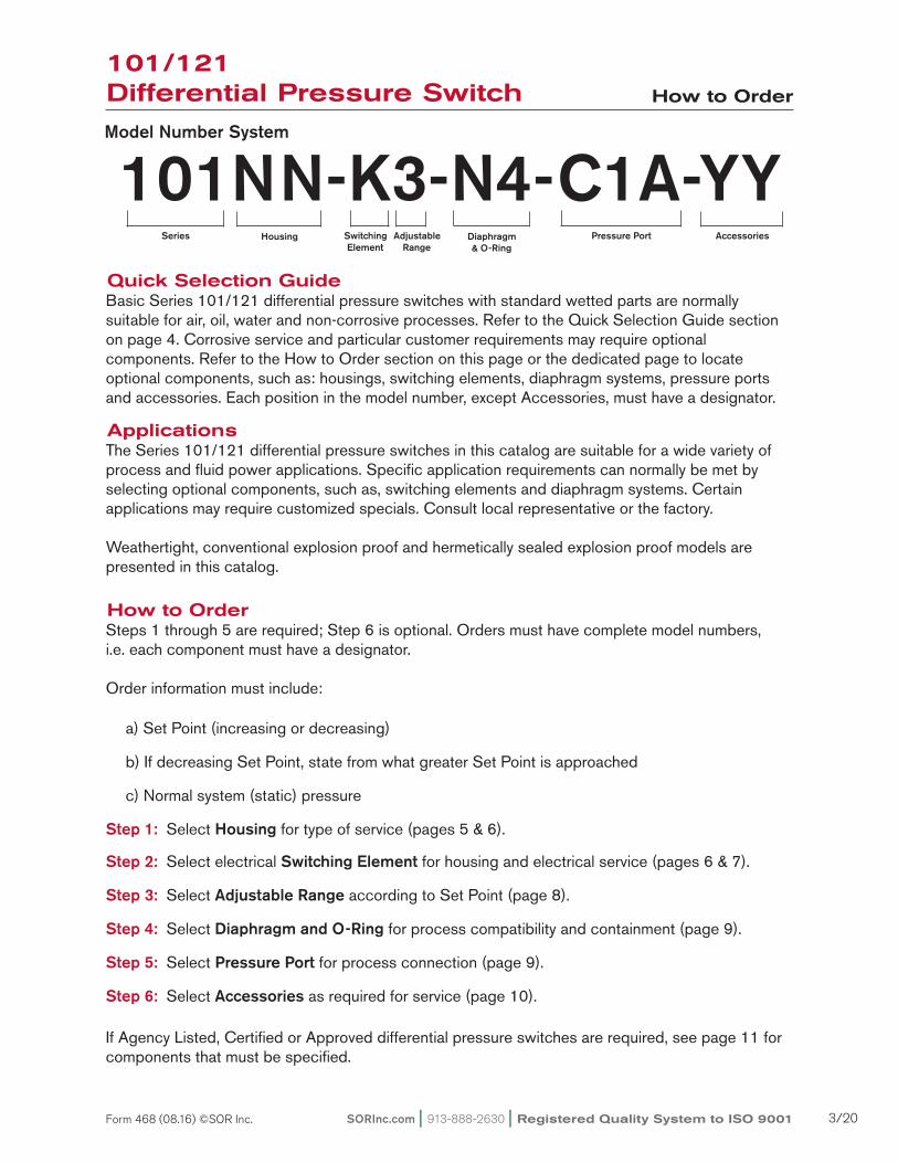
101NN-K3-N4-C1A-YYModel Number System
Series Housing Diaphragm & O-Ring
Switching Element
Adjustable Range
Pressure Port Accessories
ApplicationsThe Series 101/121 differential pressure switches in this catalog are suitable for a wide variety of process and fluid power applications. Specific application requirements can normally be met by selecting optional components, such as, switching elements and diaphragm systems. Certain applications may require customized specials. Consult local representative or the factory.
Weathertight, conventional explosion proof and hermetically sealed explosion proof models are presented in this catalog.
How to OrderSteps 1 through 5 are required; Step 6 is optional. Orders must have complete model numbers, i.e. each component must have a designator.
Order information must include: a) Set Point (increasing or decreasing)
b) If decreasing Set Point, state from what greater Set Point is approached
c) Normal system (static) pressure
Step 1: Select Housing for type of service (pages 5 & 6).
Step 2: Select electrical Switching Element for housing and electrical service (pages 6 & 7).
Step 3: Select Adjustable Range according to Set Point (page 8).
Step 4: Select Diaphragm and O-Ring for process compatibility and containment (page 9).
Step 5: Select Pressure Port for process connection (page 9).
Step 6: Select Accessories as required for service (page 10).
If agency Listed, Certified or approved differential pressure switches are required, see page 11 for components that must be specified.
101/121 Differential Pressure Switch How to Order
SORInc.com | 913-888-2630 | Registered Quality System to ISO 9001 3/20Form 468 (08.16) ©SOR Inc.
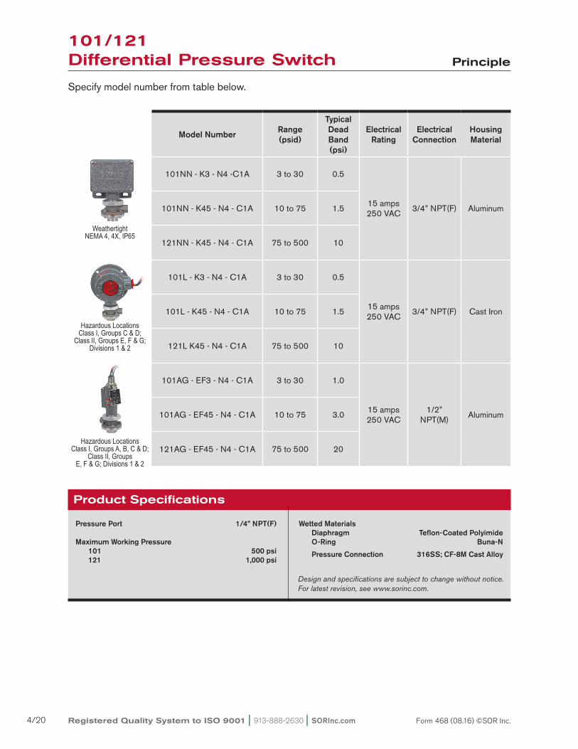
Specify model number from table below.
Weathertight NEMA 4, 4X, IP65
Hazardous Locations Class I, Groups C & D;
Class II, Groups E, F & G; Divisions 1 & 2
Hazardous Locations Class I, Groups A, B, C & D;
Class II, Groups E, F & G; Divisions 1 & 2
Pressure Port 1/4” NPT(F)
Maximum Working Pressure 101 500 psi 121 1,000 psi
Wetted Materials Diaphragm Teflon-Coated Polyimide O-Ring Buna-N
Pressure Connection 316SS; CF-8M Cast Alloy
Product Specifications
Design and specifications are subject to change without notice. For latest revision, see www.sorinc.com.
Model Number Range (psid)
Typical Dead Band (psi)
Electrical Rating
Electrical Connection
Housing Material
101NN - K3 - N4 -C1a 3 to 30 0.5
15 amps250 VaC
3/4” NPT(F) aluminum101NN - K45 - N4 - C1a 10 to 75 1.5
121NN - K45 - N4 - C1a 75 to 500 10
101L - K3 - N4 - C1a 3 to 30 0.5
15 amps250 VaC
3/4” NPT(F) Cast Iron101L - K45 - N4 - C1a 10 to 75 1.5
121L K45 - N4 - C1a 75 to 500 10
101aG - eF3 - N4 - C1a 3 to 30 1.0
15 amps250 VaC
1/2” NPT(m)
aluminum101aG - eF45 - N4 - C1a 10 to 75 3.0
121aG - eF45 - N4 - C1a 75 to 500 20
101/121 Differential Pressure Switch Principle
Registered Quality System to ISO 9001 | 913-888-2630 | SORInc.com4/20 Form 468 (08.16) ©SOR Inc.
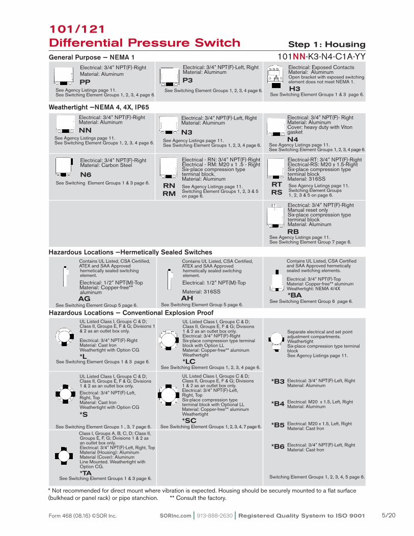
electrical: 3/4” NPT(F)-right material: aluminum
See agency Listings page 11.See Switching element Groups 1, 2, 3, 4 page 6.
electrical: 3/4” NPT(F)-right material: aluminum NN See agency Listings page 11.See Switching element Groups 1, 2, 3, 4 page 6.
Contains UL Listed, CSa Certified, aTeX and Saa approved hermetically sealed switching element.
electrical: 1/2” NPT(m)-Top material: Copper-free** aluminum AGSee Switching element Group 5 page 6.
electrical: 3/4” NPT(F)-Left, right material: aluminum
See Switching element Groups 1, 2, 3, 4 page 6.
electrical: 3/4” NPT(F)-Left, right material: aluminum N3See agency Listings page 11.See Switching element Groups 1, 2, 3, 4 page 6.
electrical: exposed Contacts material: aluminum Open bracket with exposed switching element does not meet Nema 1.
See Switching element Groups 1 & 3 page 6.
electrical: 3/4” NPT(F)-right manual reset only Six-place compression type terminal block material: aluminum See agency Listings page 11.See Switching element Group 7 page 6.
General Purpose — NEMA 1
Weathertight —NEMA 4, 4X, IP65
Hazardous Locations —Hermetically Sealed Switches
See agency Listings page 11.Switching element Groups 1, 2, 3 & 5 on page 6.
RB
PP
electrical: 3/4” NPT(F)- right material: aluminum Cover: heavy duty with Viton gasket N4See agency Listings page 11.See Switching element Groups 1, 2, 3, 4 page 6.
electrical: 3/4” NPT(F)-right material: Carbon Steel N6See Switching element Groups 1 & 3 page 6.
electrical - rN: 3/4” NPT(F)-right electrical - rm: m20 x 1 .5 - right Six-place compression type terminal block. material: aluminum See agency Listings page 11. Switching element Groups 1, 2, 3 & 5 on page 6.
RNRM
electrical-rT: 3/4” NPT(F)-right electrical-rS: m20 x 1.5-right Six-place compression type terminal block material: 316SS
RTRS
Contains UL Listed, CSa Certified and Saa approved hermetically sealed switching elements.
electrical: 3/4” NPT(F)-Top material: Copper-free** aluminum Weathertight: Nema 4/4X
*BASee Switching element Group 6 page 6.
UL Listed Class I, Groups C & D; Class II, Groups e, F & G; Divisions 1 & 2 as an outlet box only.
electrical: 3/4” NPT(F)-rightmaterial: Cast Iron Weathertight with Option CG
*L
UL Listed Class I, Groups C & D; Class II, Groups e, F & G; Divisions 1 & 2 as an outlet box only.electrical: 3/4” NPT(F)-rightSix-place compression type terminal block with Option LL material: Copper-free** aluminum Weathertight
*LC
101NN-K3-N4-C1a-YY
Separate electrical and set point adjustment compartments. Weathertight Six-place compression type terminal block See agency Listings page 11.
UL Listed Class I, Groups C & D; Class II, Groups e, F & G; Divisions 1 & 2 as an outlet box only.electrical: 3/4” NPT(F)-Left, right, Topmaterial: Cast Iron Weathertight with Option CG
*S
UL Listed Class I, Groups C & D; Class II, Groups e, F & G; Divisions 1 & 2 as an outlet box only.electrical: 3/4” NPT(F)-Left, right, TopSix-place compression type terminal block with Optional LL material: Copper-free** aluminum Weathertight
*SC
Class I, Groups a, B, C, D; Class II, Groups e, F, G; Divisions 1 & 2 as an outlet box only. electrical: 3/4” NPT(F)-Left, right, Top material (Housing): aluminum material (Cover): aluminum Line mounted. Weathertight with Option CG. *TA See Switching element Groups 1 & 3 page 6.
*B3
*B4
electrical: 3/4” NPT(F)-Left, right material: aluminum
electrical: m20 x 1.5, Left, right material: aluminum
*B5
*B6
electrical: m20 x 1.5, Left, right material: Cast Iron
electrical: 3/4” NPT(F)-Left, right material: Cast Iron
Switching element Groups 1, 2, 3, 4, 5 page 6.
* Not recommended for direct mount where vibration is expected. Housing should be securely mounted to a flat surface (bulkhead or panel rack) or pipe stanchion. ** Consult the factory.
See Switching element Groups 1 & 3 page 6.See Switching element Groups 1, 2, 3, 4 page 6.
See Switching element Groups 1 , 3, 7 page 6. See Switching element Groups 1, 2, 3, 4, 7 page 6.
Hazardous Locations — Conventional Explosion Proof
P3H3
Contains UL Listed, CSa Certified, aTeX and Saa approved hermetically sealed switching element.
electrical: 1/2” NPT(m)-Top
material: 316SS AH See Switching element Group 5 page 6.
101/121 Differential Pressure Switch Step 1: Housing
SORInc.com | 913-888-2630 | Registered Quality System to ISO 9001 5/20Form 468 (08.16) ©SOR Inc.
Switching Element Service
Electrical Contact
Type
Electrical Connection
Type
AC Rating DC Rating Resistive Dead Band Multiplier Designator
Volts Amps Volts Amps Volts Amps SPDT DPDT SPDT DPDT
Normal Service aC
250 15 125 .4* 30 5* 1 4 K KK
Low PowerGold Contacts
125 1 - - 28 1* 1 - Ka N/a
125 1 - - 30 1 1.5 3.5 J JJ
Wide Dead Band aC 250 15 125 .5 - - 2 4 G GG
aC or DC 250 11 125 .5* 30 5 2 4 a aa
Wide Dead Band DC 250 15 - - 30 10* 2.5 4.5 L LL
Narrow Dead Band DC
250 5 125 .5* 30 5* 1.5 3 e ee
Very Wide Dead Band DC
250 15 125 .5 - - 3.5 - C N/a
Very High-Capacity DCmagnetic Blow-Out
125 10 125
1.5 minimum
10maximum
- - 3.5 - S N/a
Hi-ambient Temperature rating - 400°F
250 5 125 .3 - - 2 4 B BB
250 5 125 .5* - - 1.5 3.5 Y YY
250 5 125 .3* - - 1 - W N/a
Wide adjustable Dead Band
250 15 125 .4* - -2.5 to 5
- T N/a
Narrow adjustable Dead Band
250 15 - - - - 1 to 3 - H N/a
manual reset - Decreasing Pressure (automatic actuation Increasing Pressure)
250 15 125 .5 - - 1.5 -
D N/a
manual reset - Increasing Pressure (automatic actuation Decreasing Pressure)
m N/a
Corrosion resistant explosion Proof Hermetically Sealed Switching element
250 15 125 .4* 30 5* 1.5 - KB N/a
250 5 125 .5* 30 5* - 3.5 N/a eB
250 11 125 .5 30 5 3 5 aF aG
250 5 125 .5* 30 5* 2 3.5 eF eG
Corrosion resistant explosion Proof Lower Power Service Hermetically Sealed Gold Contacts
125 1 - - 28 1* 1.5 - Jr N/a
125 1 - - 30 1 - 4 N/a JB
125 1 - - 30 1 2.5 4 JF JG
aTeX approved II 2 G eex d IIC microswitch Only
250 7 250 0.25 30 7 1 - BD N/a
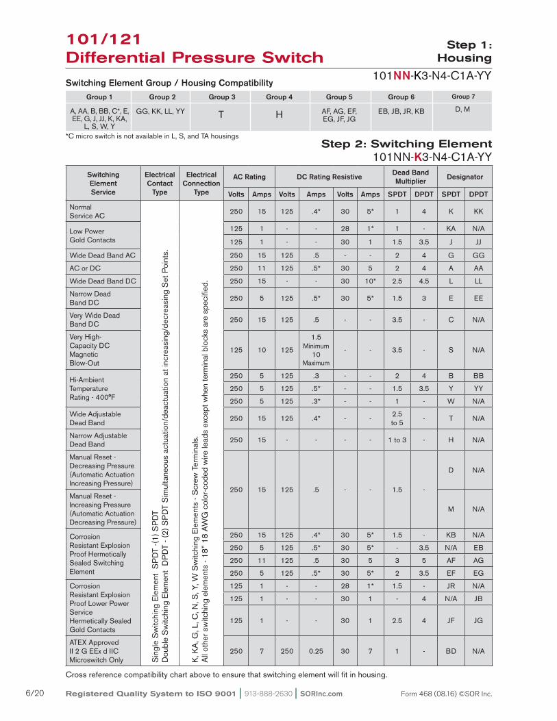
Switching Element Group / Housing Compatibility
*C micro switch is not available in L, S, and Ta housings
Group 2
GG, KK, LL, YY
Group 3
T
Group 4
H
Group 5
aF, aG, eF, eG, JF, JG
Group 6
eB, JB, Jr, KB
Group 7
D, m
Group 1
a, aa, B, BB, C*, e, ee, G, J, JJ, K, Ka,
L, S, W, Y
Step 2: Switching Element
Step 1:
Housing
101NN-K3-N4-C1a-YY
Cross reference compatibility chart above to ensure that switching element will fit in housing.
Sin
gle
Sw
itchi
ng e
lem
ent
SP
DT
-(1)
SP
DT
Dou
ble
Sw
itchi
ng e
lem
ent
DP
DT
- (2)
SP
DT
Sim
ulta
neou
s ac
tuat
ion/
deac
tuat
ion
at in
crea
sing
/dec
reas
ing
Set
Poi
nts.
K, K
a, G
, L, C
, N, S
, Y, W
Sw
itchi
ng e
lem
ents
- S
crew
Ter
min
als.
all
othe
r sw
itchi
ng e
lem
ents
- 18
” 18
aW
G c
olor
-cod
ed w
ire le
ads
exce
pt w
hen
term
inal
blo
cks
are
spec
ified
.
101NN-K3-N4-C1a-YY
101/121 Differential Pressure Switch
Registered Quality System to ISO 9001 | 913-888-2630 | SORInc.com6/20 Form 468 (08.16) ©SOR Inc.

Notes1. aC/DC electrical ratings for switching elements K, KK, Ka, J, JJ, G, GG, a, aa, L, LL, e, ee, C, S, B, BB, Y, YY, W, T, H, D and m are UL recognized and CSa Certified with conditions and exceptions specified in Note 3.2. The hermetically sealed switching element capsule is UL Listed, CSa Certified, aTeX and TestSafe approved as a snap switch in accordance with the following table with conditions and exceptions specified in Note 3.
3. DC electrical ratings are for resistive loads only. DC ratings marked with an asterisk (*) are not agency recognized or certified but have been verified by testing or experience.
Step 2:
Switching Element
101NN-K3-N4-C1a-YY
4. DPDT switching elements have wire leads except when supplied in housings rN, rT, rm, rS, rB, B3, B4, B5, B6.5. Switching element minimum/maximum ambient temperatures: -40 to 167oF (-40 to 75oC) aF, aG, eB, eF, eG, JB, JF, JG, Jr, KB -65 to 400oF (-54 to 204oC) B, Y, W -65 to 250oF (-54 to 120oC) a, e, J -65 to 180oF (-54 to 80oC) all others6. Dead band multipliers must be applied to the typical dead band figures given in the specification tables on page 8.7. Switching elements B, W and Y have an elgiloy spring. experience indicates good service in atmospheres with corrosive gases - H2S, ammonia, etc.
Caution: The switching element assembly has been precisely positioned in the housing at the factory for optimum performance. any inadver-tent movement or replacement in the field will degrade performance, could render the device inoperative and may void the warranty unless factory authorized procedures are followed.
Agency Hazardous Location Conditions Designator
UL ListedCSa Certified
Class I, Groups a, B, C & D; Class II, Groups e, F & G; Divisions 1 & 2
aF, eF, aG, eG, KB, eB, JB, JF,
JG, Jr
TestSafe approved
ex s Zone 2 IIC T4 IP65ex tD a22 T105°C IP65
aF, eF, aG, eG, KB, eB
aTeX approved II 2 G eex m IIaF, eF, aG, eG, JF, JG
101/121 Differential Pressure Switch
SORInc.com | 913-888-2630 | Registered Quality System to ISO 9001 7/20Form 468 (08.16) ©SOR Inc.
Step 3:
Adjustable Range
101NN-K3-N4-C1a-YY
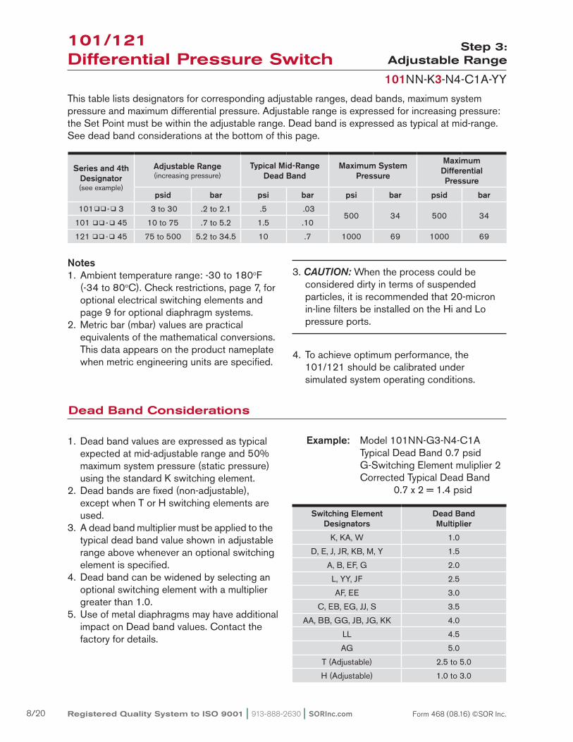
This table lists designators for corresponding adjustable ranges, dead bands, maximum system pressure and maximum differential pressure. adjustable range is expressed for increasing pressure: the Set Point must be within the adjustable range. Dead band is expressed as typical at mid-range. See dead band considerations at the bottom of this page.
Notes1. ambient temperature range: -30 to 180oF (-34 to 80oC). Check restrictions, page 7, for optional electrical switching elements and page 9 for optional diaphragm systems.2. metric bar (mbar) values are practical equivalents of the mathematical conversions. This data appears on the product nameplate when metric engineering units are specified.
3. Caution: When the process could be considered dirty in terms of suspended particles, it is recommended that 20-micron in-line filters be installed on the Hi and Lo pressure ports.
4. To achieve optimum performance, the 101/121 should be calibrated under simulated system operating conditions.
Dead Band Considerations
1. Dead band values are expressed as typical expected at mid-adjustable range and 50% maximum system pressure (static pressure) using the standard K switching element.2. Dead bands are fixed (non-adjustable), except when T or H switching elements are used.3. a dead band multiplier must be applied to the typical dead band value shown in adjustable range above whenever an optional switching element is specified.4. Dead band can be widened by selecting an optional switching element with a multiplier greater than 1.0.5. Use of metal diaphragms may have additional impact on Dead band values. Contact the factory for details.
Switching Element Designators
Dead Band Multiplier
K, Ka, W 1.0
D, e, J, Jr, KB, m, Y 1.5
a, B, eF, G 2.0
L, YY, JF 2.5
aF, ee 3.0
C, eB, eG, JJ, S 3.5
aa, BB, GG, JB, JG, KK 4.0
LL 4.5
aG 5.0
T (adjustable) 2.5 to 5.0
H (adjustable) 1.0 to 3.0
Series and 4th Designator (see example)
Adjustable Range(increasing pressure)
Typical Mid-Range Dead Band
Maximum System Pressure
Maximum DifferentialPressure
psid bar psi bar psi bar psid bar
101 - 3 3 to 30 .2 to 2.1 .5 .03500 34 500 34
101 - 45 10 to 75 .7 to 5.2 1.5 .10
121 - 45 75 to 500 5.2 to 34.5 10 .7 1000 69 1000 69
101/121 Differential Pressure Switch
Example: model 101NN-G3-N4-C1a Typical Dead Band 0.7 psid G-Switching element muliplier 2 Corrected Typical Dead Band 0.7 x 2 = 1.4 psid
Registered Quality System to ISO 9001 | 913-888-2630 | SORInc.com8/20 Form 468 (08.16) ©SOR Inc.
Step 4:
Diaphragm & O-Ring
101NN-K3-N4-C1a-YY
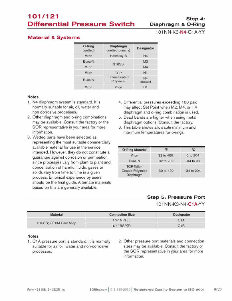
Notes1. N4 diaphragm system is standard. It is normally suitable for air, oil, water and non-corrosive processes.2. Other diaphragm and o-ring combinations may be available. Consult the factory or the SOr representative in your area for more information.3. Wetted parts have been selected as representing the most suitable commercially available material for use in the service intended. However, they do not constitute a guarantee against corrosion or permeation, since processes vary from plant to plant and concentration of harmful fluids, gases or solids vary from time to time in a given process. empirical experience by users should be the final guide. alternate materials based on this are generally available.
4. Differential pressures exceeding 100 psid may affect Set Point when m2, m4, or H4 diaphragm and o-ring combination is used.5. Dead bands are higher when using metal diaphragm options. Consult the factory.6. This table shows allowable minimum and maximum temperatures for o-rings.
Step 5: Pressure Port
101NN-K3-N4-C1A-YY
Notes1. C1a pressure port is standard. It is normally suitable for air, oil, water and non-corrosive processes.
2. Other pressure port materials and connection sizes may be available. Consult the factory or the SOr representative in your area for more information.
Material & Systems
O-Ring (wetted)
Diaphragm (wetted primary) Designator
Viton Hastelloy-B H4
Buna-N316SS
m2
Viton m4
Viton TCP Teflon-Coated
Polyimide
N1
Buna-N N4 Standard
Viton Viton S1
O-Ring Material °F °C
Viton 32 to 400 0 to 204
Buna-N -32 to 200 -34 to 93
TCP-Teflon Coated Polyimide
Diaphragm-30 to 400 -34 to 204
Material Connection Size Designator
316SS; CF-8m Cast alloy1/4” NPT(F) C1a
1/4” BSP(F) C1B
101/121 Differential Pressure Switch
SORInc.com | 913-888-2630 | Registered Quality System to ISO 9001 9/20Form 468 (08.16) ©SOR Inc.
Step 6: Accessories
101NN-K3-N4-C1a-YY
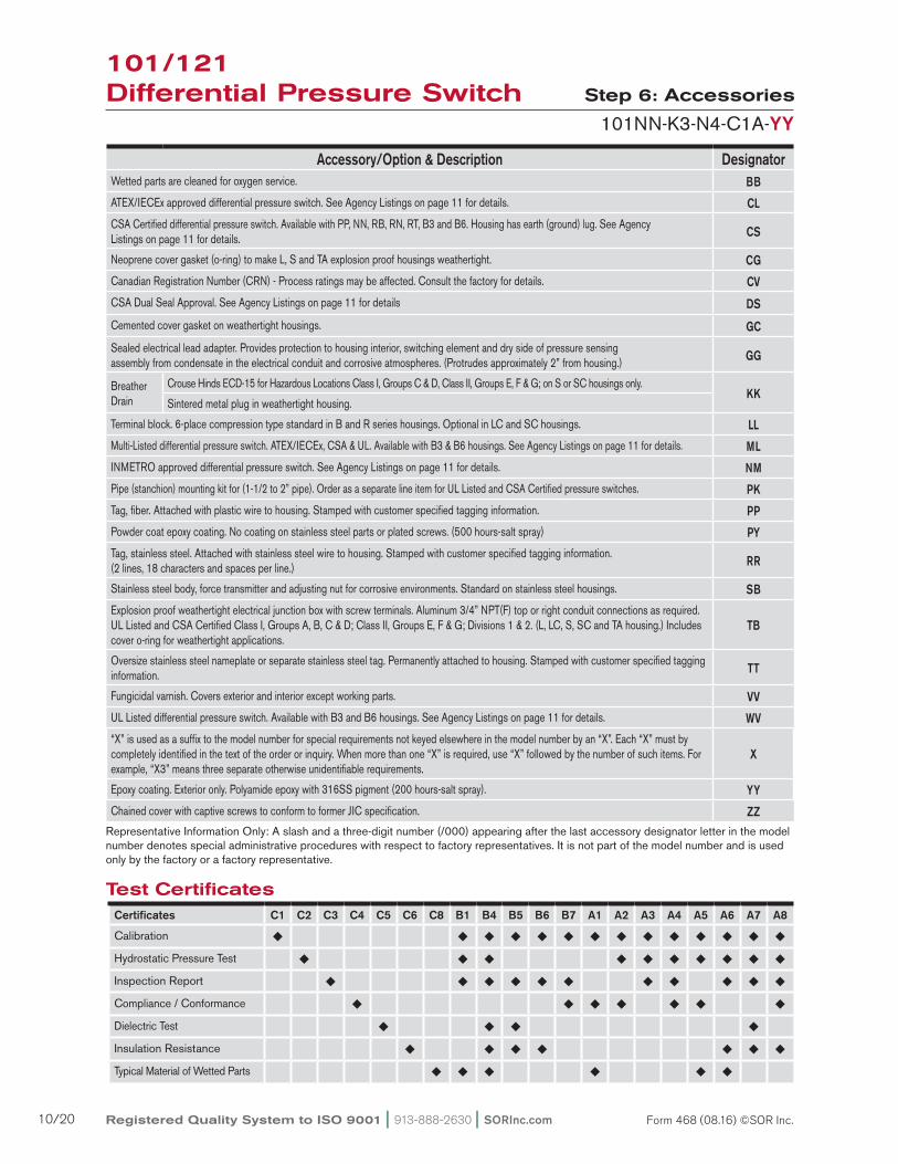
representative Information Only: a slash and a three-digit number (/000) appearing after the last accessory designator letter in the model number denotes special administrative procedures with respect to factory representatives. It is not part of the model number and is used only by the factory or a factory representative.
Accessory/Option & Description Designator Wetted parts are cleaned for oxygen service. BB
aTeX/IeCex approved differential pressure switch. See agency Listings on page 11 for details. CL
CSa Certified differential pressure switch. available with PP, NN, rB, rN, rT, B3 and B6. Housing has earth (ground) lug. See agency Listings on page 11 for details. CS
Neoprene cover gasket (o-ring) to make L, S and Ta explosion proof housings weathertight. CG
Canadian registration Number (CrN) - Process ratings may be affected. Consult the factory for details. CV
CSa Dual Seal approval. See agency Listings on page 11 for details DS
Cemented cover gasket on weathertight housings. GC
Sealed electrical lead adapter. Provides protection to housing interior, switching element and dry side of pressure sensing assembly from condensate in the electrical conduit and corrosive atmospheres. (Protrudes approximately 2” from housing.) GG
Breather Drain
Crouse Hinds eCD-15 for Hazardous Locations Class I, Groups C & D, Class II, Groups e, F & G; on S or SC housings only.KK
Sintered metal plug in weathertight housing.
Terminal block. 6-place compression type standard in B and r series housings. Optional in LC and SC housings. LL
multi-Listed differential pressure switch. aTeX/IeCex, CSa & UL. available with B3 & B6 housings. See agency Listings on page 11 for details. ML
INmeTrO approved differential pressure switch. See agency Listings on page 11 for details. NM
Pipe (stanchion) mounting kit for (1-1/2 to 2” pipe). Order as a separate line item for UL Listed and CSa Certified pressure switches. PK
Tag, fiber. attached with plastic wire to housing. Stamped with customer specified tagging information. PP
Powder coat epoxy coating. No coating on stainless steel parts or plated screws. (500 hours-salt spray) PY
Tag, stainless steel. attached with stainless steel wire to housing. Stamped with customer specified tagging information. (2 lines, 18 characters and spaces per line.) RR
Stainless steel body, force transmitter and adjusting nut for corrosive environments. Standard on stainless steel housings. SB
explosion proof weathertight electrical junction box with screw terminals. aluminum 3/4” NPT(F) top or right conduit connections as required. UL Listed and CSa Certified Class I, Groups a, B, C & D; Class II, Groups e, F & G; Divisions 1 & 2. (L, LC, S, SC and Ta housing.) Includes cover o-ring for weathertight applications.
TB
Oversize stainless steel nameplate or separate stainless steel tag. Permanently attached to housing. Stamped with customer specified tagging information. TT
Fungicidal varnish. Covers exterior and interior except working parts. VV
UL Listed differential pressure switch. available with B3 and B6 housings. See agency Listings on page 11 for details. WV
“X” is used as a suffix to the model number for special requirements not keyed elsewhere in the model number by an “X”. each “X” must by completely identified in the text of the order or inquiry. When more than one “X” is required, use “X” followed by the number of such items. For example, “X3” means three separate otherwise unidentifiable requirements.
X
epoxy coating. exterior only. Polyamide epoxy with 316SS pigment (200 hours-salt spray). YY
Chained cover with captive screws to conform to former JIC specification. ZZ
101/121 Differential Pressure Switch
Test CertificatesCertificates C1 C2 C3 C4 C5 C6 C8 B1 B4 B5 B6 B7 A1 A2 A3 A4 A5 A6 A7 A8
Calibration ¿ ¿ ¿ ¿ ¿ ¿ ¿ ¿ ¿ ¿ ¿ ¿ ¿ ¿
Hydrostatic Pressure Test ¿ ¿ ¿ ¿ ¿ ¿ ¿ ¿ ¿ ¿
Inspection report ¿ ¿ ¿ ¿ ¿ ¿ ¿ ¿ ¿ ¿ ¿
Compliance / Conformance ¿ ¿ ¿ ¿ ¿ ¿ ¿
Dielectric Test ¿ ¿ ¿ ¿
Insulation resistance ¿ ¿ ¿ ¿ ¿ ¿ ¿
Typical material of Wetted Parts ¿ ¿ ¿ ¿ ¿ ¿
Registered Quality System to ISO 9001 | 913-888-2630 | SORInc.com10/20 Form 468 (08.16) ©SOR Inc.
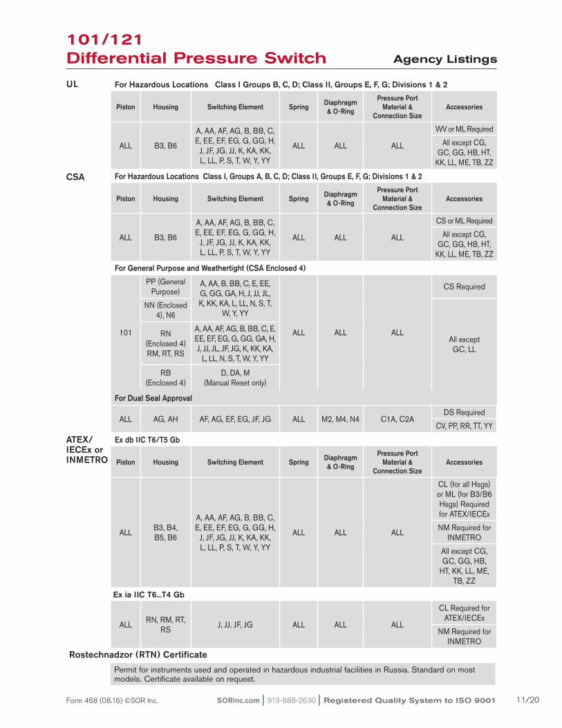
Agency Listings
UL
CSA
ATEX/IECEx or INMETRO
For Hazardous Locations Class I Groups B, C, D; Class II, Groups E, F, G; Divisions 1 & 2
Piston Housing Switching Element Spring Diaphragm & O-Ring
Pressure Port Material &
Connection SizeAccessories
aLL B3, B6
a, aa, aF, aG, B, BB, C, e, ee, eF, eG, G, GG, H,
J, JF, JG, JJ, K, Ka, KK, L, LL, P, S, T, W, Y, YY
aLL aLL aLL
WV or mL required
all except CG, GC, GG, HB, HT,
KK, LL, me, TB, ZZ
For Hazardous Locations Class I, Groups A, B, C, D; Class II, Groups E, F, G; Divisions 1 & 2
Piston Housing Switching Element Spring Diaphragm & O-Ring
Pressure Port Material &
Connection SizeAccessories
aLL B3, B6
a, aa, aF, aG, B, BB, C, e, ee, eF, eG, G, GG, H,
J, JF, JG, JJ, K, Ka, KK, L, LL, P, S, T, W, Y, YY
aLL aLL aLL
CS or mL required
all except CG, GC, GG, HB, HT,
KK, LL, me, TB, ZZ
For General Purpose and Weathertight (CSA Enclosed 4)
101
PP (General Purpose)
a, aa, B, BB, C, e, ee, G, GG, Ga, H, J, JJ, JL, K, KK, Ka, L, LL, N, S, T,
W, Y, YY
aLL aLL aLL
CS required
NN (enclosed 4), N6
all except GC, LL
rN (enclosed 4)rm, rT, rS
a, aa, aF, aG, B, BB, C, e, ee, eF, eG, G, GG, Ga, H, J, JJ, JL, JF, JG, K, KK, Ka,
L, LL, N, S, T, W, Y, YY
rB (enclosed 4)
D, Da, m (manual reset only)
For Dual Seal Approval
aLL aG, aH aF, aG, eF, eG, JF, JG aLL m2, m4, N4 C1a, C2aDS required
CV, PP, rr, TT, YY
Ex db IIC T6/T5 Gb
Piston Housing Switching Element Spring Diaphragm & O-Ring
Pressure Port Material &
Connection SizeAccessories
aLLB3, B4,B5, B6
a, aa, aF, aG, B, BB, C, e, ee, eF, eG, G, GG, H,
J, JF, JG, JJ, K, Ka, KK, L, LL, P, S, T, W, Y, YY
aLL aLL aLL
CL (for all Hsgs) or mL (for B3/B6 Hsgs) required for aTeX/IeCex
Nm required for INmeTrO
all except CG, GC, GG, HB,
HT, KK, LL, me, TB, ZZ
aLLrN, rm, rT,
rSJ, JJ, JF, JG aLL aLL aLL
CL required for aTeX/IeCex
Nm required for INmeTrO
Permit for instruments used and operated in hazardous industrial facilities in russia. Standard on most models. Certificate available on request.
101/121 Differential Pressure Switch
Ex ia IIC T6...T4 Gb
Rostechnadzor (RTN) Certificate
SORInc.com | 913-888-2630 | Registered Quality System to ISO 9001 11/20Form 468 (08.16) ©SOR Inc.

Manual Reset
101RB-D3-N4-C1a-YYSeries 101/121 Differential Pressure Switches in this catalog may be specified with manual reset electrical switching elements D or m. D actuates automatically on increasing pressure. m actuates automatically on decreasing pressure. Depress the button, covered by the weathertight boot to manually reset. Housings must be rB weathertight or S explosion proof because of the requirement of a hub for the manual reset assembly. refer to page 3 for order instructions.
Approximate Weights
actual shipping weights may vary from the charted values because of product material, configuration and packaging requirements.
RB-Weathertight S-Explosion Proof
Housing Weight (lbs.) (kgs)
aG, H3 2.5 1.25
aH, NN, N3, N4, PP, P3 3 1.5
rm, rN 3.5 1.75
Ba, N6, rB 4 2
rT 4.5 2.25
L, LC, SC 5 2.5
Ta 5.5 2.75
B3. B4 9 4.5
B5, B6 11 5.5
Accessory Add (lbs.) (kgs)
PK Pipe Kit 1.5 0.7
TB Junction Box with Terminal Block
5 2.25
101/121 Differential Pressure Switch
Registered Quality System to ISO 9001 | 913-888-2630 | SORInc.com12/20 Form 468 (08.16) ©SOR Inc.
SOr recognizes that there is no industry convention with respect to terminology and definitions pertinent to pressure switches. This glossary applies to SOr Pressure Switches.
Adjustable Range The span of pressure between upper and lower limits within which the pressure switch may be adjusted to actuate/deactuate. It is expressed for increasing differential pressure.
Dead Band The difference in pressure between the increasing Set Point and the decreasing Set Point. It is expressed as “typical,” which is an average with the increasing Set Point at mid- adjustable range for a pressure switch with the standard K switching element. It is normally fixed (nonadjustable).
Differential Pressure Switcha bi-stable electromechanical device that actuates/deactuates one or more electrical switching element(s) at a predetermined discrete differential pressure (Set Point) upon rising or falling differential pressure.
DPDT Switching ElementDPDT is two synchronized SPDT switching elements that actuate together at increasing Set Point and deactuate together at decreasing Set Point. Discrete SPDT switching elements allow two independent circuits to be switched; i.e., one aC and one DC.
The synchronization linkage is factory set, and is not field adjustable. Synchronization is verified by connecting test lamps to the switching elements and observing them go“On” simultaneously at actuation and “Off” simultaneously at deactuation
Hermetically Sealed a welded steel capsule with glass-to-metal, factory-sealed, electrical leads that isolates the electrical switching element(s) from the environment.
Maximum Differential PressureThe maximum difference in pressure that may be continuously applied between the Hi and Lo (Lo and Hi) pressure ports without causing permanent change of Set Point, leakage or material failure.
OverrangeThe maximum input pressure that may be continuously applied to the pressure switch without causing permanent change of Set Point, leakage or material failure.
Proof PressureThe maximum input pressure that may be continuously applied to the pressure switch without causing leakage or catastrophic material failure. Permanent change of Set Points may occur, or the device may be rendered inoperative.
RepeatabilityThe ability of a pressure switch to successively operate at a Set Point that is approached from a starting point in the same direction and returns to the starting point over three consecutive cycles to establish a pressure profile. The closeness of the measured Set Point values is normally expressed as a percentage of full scale (maximum adjustable range pressure).
Set PointThat discrete pressure at which the pressure switch is adjusted to actuate/deactuate on rising or falling pressure. It must fall within the adjustable range and be called out as increasing or decreasing differential pressure.
SPDT Switching Element Single-Pole, Double Throw (SPDT) has three connections: C — Common, NO — Normally Open and NC — Normally Closed, which allows the switching element to be electrically connected to the circuit in either NO or NC state.
Glossary of Terms
101/121 Differential Pressure Switch
SORInc.com | 913-888-2630 | Registered Quality System to ISO 9001 13/20Form 468 (08.16) ©SOR Inc.
ISO-9001
14685 W 105TH ST LENEXA, KS 66215 USA913-888-2630SORINC.COM
ATYP
7.10.28
40.51.59
26.11.03
28.61.13
** 56.52.22
60.32.38
28.61.13
61.92.44
154.16.07
38.11.50
108.14.25
69.92.75
52.42.06
33.31.31
PROCESSCONNECTION SIZE LENGTH A
1/4 NPTMSHOWN
29.71.17
1/2 NPTF 37.61.48
1/2 NPTM 34.81.37
3/4 NPTF 39.91.57
HOUSINGGROUP ** DIMENSION
NN & N3 SHOWN
N4 4.6ADD 0.18
PP & P3 1.5SUBTRACT 0.06
Model Name: 0090602.ASSEM/2/2
PRODUCT CERTIFICATION DRAWINGALL DIMENSIONS ARE ±1/16 INUNLESS OTHERWISE SPECIFIED
MMLINEAR = IN
DRAWN BY
K MITCHELLCHECKED BY
J REHMENGINEER APPROVAL
J MODIGDATE
10 OCT 2011THIS DRAWING IS THE EXCLUSIVE PROPERTY OF SOR.
NO USE WHATSOEVER OF THE INFORMATION CONTAINEDHEREON, NOR REPRODUCTION IN WHOLE OR PART MAY BE
MADE WITHOUT THE EXPRESS WRITTEN PERMISSION OF SOR.
TITLE
DIMENSION DRAWING 101/121NN, N3, N4, PP & P3
EO NUMBER: 5123
SCALE: 1.00
DO NOT SCALE PRINT
DRAWING NUMBER REV
0090602 3
SHEET 1 OF 1DWG SIZE
B
MODEL # SALES ORDER # LINE ITEM # PURCHASE ORDER #SALES PAGE
CLEARANCE SLOTS
FOR 6.40.25 HARDWARE WITH
63.52.50 MIN TO 76.2
3.00 MAX
MOUNTING CENTERS
1/4 NPTF HI SIDEPROCESS CONNECTION
1/4 NPTF LO SIDEPROCESS CONNECTION
ELECTRICALCONNECTION3/4 NPTF STD1/2 NPTF OPT
(BOTH SIDES ONN3 & P3 HSGS)
1
Reset Form
ISO-9001
14685 W 105TH ST LENEXA, KS 66215 USA913-888-2630SORINC.COM
9.50.38
6.30.25
19.50.77
49.21.94
30.11.1960.3
2.38
28.61.13
66.92.63
132.05.20
159.86.29
ELECTRICALCONNECTION
3/4 NPT(F)(STD)1/2 NPT(F)(OPT)
27.71.09
48.51.91
95.63.76
38.11.50
68.32.69
63.52.50
A(TYP)
MOUNTING
HOLE (TYP 2)
7.10.28
Model Name: 0090603.ASSEM/3/1+
PRODUCT CERTIFICATION DRAWINGALL DIMENSIONS ARE ± 1/16 INUNLESS OTHERWISE SPECIFIED
MMLINEAR = IN
DRAWN BY
J FIXSEN CHECKED BY
M SMITH ENGINEER APPROVAL
J MODIG DATE
11/26/02 THIS DRAWING IS THE EXCLUSIVE PROPERTY OF SOR.
NO USE WHATSOEVER OF THE INFORMATION CONTAINEDHEREON, NOR REPRODUCTION IN WHOLE OR PART MAY BE
MADE WITHOUT THE EXPRESS WRITTEN PERMISSION OF SOR.
TITLE
DIM DWG 101/121 N6
EO NUMBER: 4441
SCALE: 0.65DO NOT SCALE PRINT
DRAWING NUMBER REV
0090603 3
SHEET 1 OF 1DWG SIZE
B
MODEL # SALES ORDER # LINE ITEM # PURCHASE ORDER #SALES PAGE
LENGTH A29.71/4 NPT(M) = (SHOWN)1.17
37.61/2 NPT(F) = 1.48
34.81/2 NPT(M) = 1.37
39.93/4 NPT(F) = 1.57
1/4 NPT(F) HI SIDEPROCESS CONNECTION
1/4 NPT(F) LO SIDEPROCESS CONNECTION
1
Reset Form
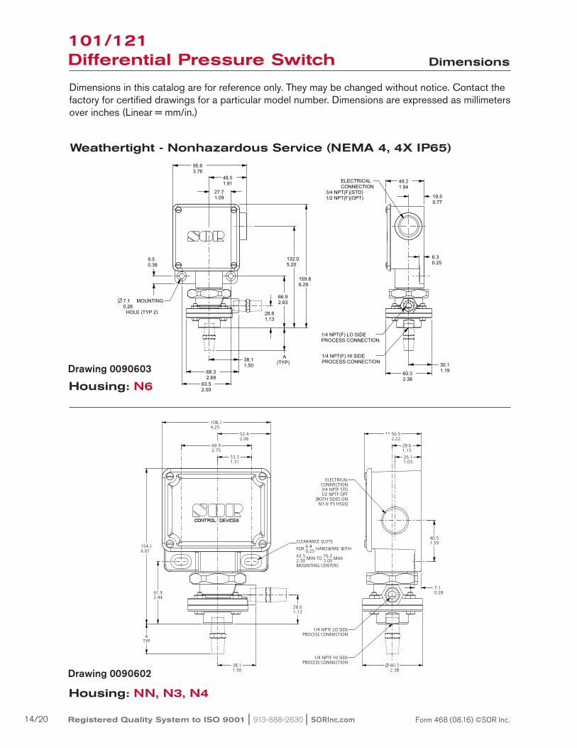
101/121 Differential Pressure Switch Dimensions
Dimensions in this catalog are for reference only. They may be changed without notice. Contact the factory for certified drawings for a particular model number. Dimensions are expressed as millimeters over inches (Linear = mm/in.)
Housing: N6
Weathertight - Nonhazardous Service (NEMA 4, 4X IP65)
Housing: NN, N3, N4
Drawing 0090603
Drawing 0090602
Registered Quality System to ISO 9001 | 913-888-2630 | SORInc.com14/20 Form 468 (08.16) ©SOR Inc.
ISO-9001
14685 W 105TH ST LENEXA, KS 66215 USA913-888-2630SORINC.COM
28.61.12
26.21.03
65.62.58
7.10.28
28.61.13
61.92.44
179.17.05
ATYP
38.11.50
52.02.05
107.34.22
33.31.31
69.92.75
CLEARANCE SLOTS
FOR 6.40.25 HARDWARE
WITH 63.52.50 MIN TO 76.2
3.00 MAX
MOUNTING CENTERS
ELECTRICALCONNECTION
SEE CHART
40.51.59
Model Name: 0090605.ASSEM/4/0+
PRODUCT CERTIFICATION DRAWINGALL DIMENSIONS ARE ±1/16 INUNLESS OTHERWISE SPECIFIED
MMLINEAR = IN
DRAWN BY
K MITCHELLCHECKED BY
M SMITHENGINEER APPROVAL
S BOALDATE
12 NOV 2012THIS DRAWING IS THE EXCLUSIVE PROPERTY OF SOR.
NO USE WHATSOEVER OF THE INFORMATION CONTAINEDHEREON, NOR REPRODUCTION IN WHOLE OR PART MAY BE
MADE WITHOUT THE EXPRESS WRITTEN PERMISSION OF SOR.
TITLE
DIMENSION DRAWING 101/121 R-SERIES HOUSING
EO NUMBER: 5195
SCALE: 0.85
DO NOT SCALE PRINT
DRAWING NUMBER REV
0090605 5
SHEET 1 OF 1DWG SIZE
B
MODEL # SALES ORDER # LINE ITEM # PURCHASE ORDER #SALES PAGE
HOUSING ELECTRICALCONNECTION
RL3/4 NPTF STD1/2 NPTF OPT
LH & RH
RM M20 X 1.5 FRH ONLY
RN3/4 NPTF STD1/2 NPTF OPT
RH ONLY
RS M20 X 1.5 FRH ONLY
RT3/4 NPTF STD1/2 NPTF OPT
RH ONLY
RU3/4 NPTF STD1/2 NPTF OPT
LH & RH
RW M20 X 1.5 FLH & RH
RY M20 X 1.5 FLH & RH
PROCESSCONNECTION SIZE LENGTH A
1/4 NPTMSHOWN
29.71.17
1/2 NPTF 37.61.48
1/2 NPTM 34.81.37
3/4 NPTF 39.91.57
2X PROCESSCONNECTIONOPTIONAL
1/4 NPTFHI SIDE
PROCESSCONNECTION
1/4 NPTFLO SIDEPROCESSCONNECTION
1
Reset Form
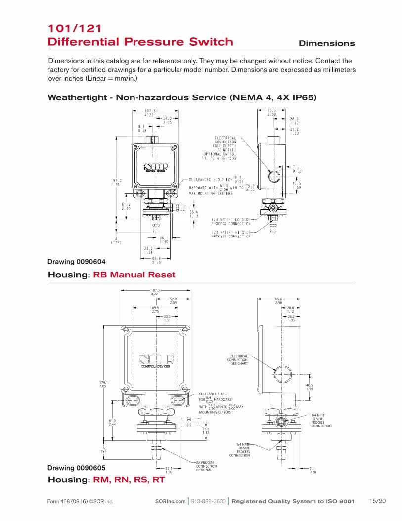
101/121Differential Pressure Switch Dimensions
Dimensions in this catalog are for reference only. They may be changed without notice. Contact the factory for certified drawings for a particular model number. Dimensions are expressed as millimeters over inches (Linear = mm/in.)
Housing: RB Manual Reset
Housing: RM, RN, RS, RT
Weathertight - Non-hazardous Service (NEMA 4, 4X IP65)
Drawing 0090604
Drawing 0090605
SORInc.com | 913-888-2630 | Registered Quality System to ISO 9001 15/20Form 468 (08.16) ©SOR Inc.
ISO-9001
14685 W 105TH ST LENEXA, KS 66215 USA913-888-2630SORINC.COM
ATYP
7.10.28
40.51.59
26.11.03
28.61.13
** 56.52.22
60.32.38
28.61.13
61.92.44
154.16.07
38.11.50
108.14.25
69.92.75
52.42.06
33.31.31
PROCESSCONNECTION SIZE LENGTH A
1/4 NPTMSHOWN
29.71.17
1/2 NPTF 37.61.48
1/2 NPTM 34.81.37
3/4 NPTF 39.91.57
HOUSINGGROUP ** DIMENSION
NN & N3 SHOWN
N4 4.6ADD 0.18
PP & P3 1.5SUBTRACT 0.06
Model Name: 0090602.ASSEM/2/2
PRODUCT CERTIFICATION DRAWINGALL DIMENSIONS ARE ±1/16 INUNLESS OTHERWISE SPECIFIED
MMLINEAR = IN
DRAWN BY
K MITCHELLCHECKED BY
J REHMENGINEER APPROVAL
J MODIGDATE
10 OCT 2011THIS DRAWING IS THE EXCLUSIVE PROPERTY OF SOR.
NO USE WHATSOEVER OF THE INFORMATION CONTAINEDHEREON, NOR REPRODUCTION IN WHOLE OR PART MAY BE
MADE WITHOUT THE EXPRESS WRITTEN PERMISSION OF SOR.
TITLE
DIMENSION DRAWING 101/121NN, N3, N4, PP & P3
EO NUMBER: 5123
SCALE: 1.00
DO NOT SCALE PRINT
DRAWING NUMBER REV
0090602 3
SHEET 1 OF 1DWG SIZE
B
MODEL # SALES ORDER # LINE ITEM # PURCHASE ORDER #SALES PAGE
CLEARANCE SLOTS
FOR 6.40.25 HARDWARE WITH
63.52.50 MIN TO 76.2
3.00 MAX
MOUNTING CENTERS
1/4 NPTF HI SIDEPROCESS CONNECTION
1/4 NPTF LO SIDEPROCESS CONNECTION
ELECTRICALCONNECTION3/4 NPTF STD1/2 NPTF OPT
(BOTH SIDES ONN3 & P3 HSGS)
1
Reset Form
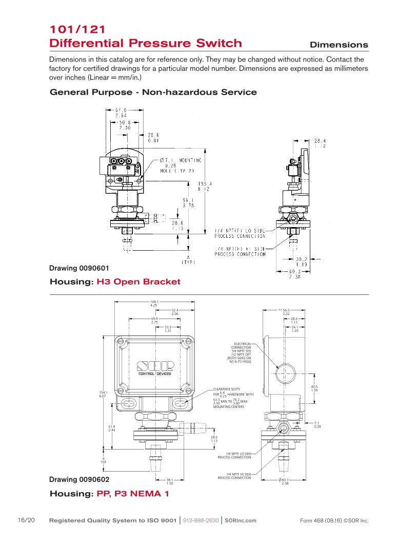
101/121 Differential Pressure Switch Dimensions
Dimensions in this catalog are for reference only. They may be changed without notice. Contact the factory for certified drawings for a particular model number. Dimensions are expressed as millimeters over inches (Linear = mm/in.)
Housing: H3 Open Bracket
General Purpose - Non-hazardous Service
Housing: PP, P3 NEMA 1
Drawing 0090601
Drawing 0090602
Registered Quality System to ISO 9001 | 913-888-2630 | SORInc.com16/20 Form 468 (08.16) ©SOR Inc.
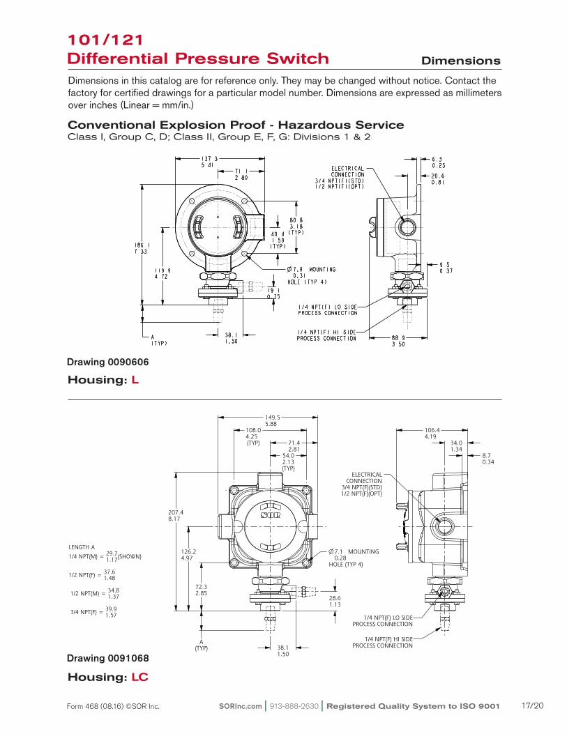
101/121 Differential Pressure Switch Dimensions
Dimensions in this catalog are for reference only. They may be changed without notice. Contact the factory for certified drawings for a particular model number. Dimensions are expressed as millimeters over inches (Linear = mm/in.)
Housing: L
Housing: LC
Conventional Explosion Proof - Hazardous ServiceClass I, Group C, D; Class II, Group E, F, G: Divisions 1 & 2
Drawing 0090606
Drawing 0091068
ISO-9001
14685 W 105TH ST LENEXA, KS 66215 USA913-888-2630SORINC.COM
149.55.88
71.42.81
8.70.34
34.01.34
106.44.19
108.04.25(TYP)
54.02.13(TYP)
72.32.85
126.24.97
207.48.17
A(TYP) 38.1
1.50
28.61.13
MOUNTING
HOLE (TYP 4)
7.10.28
ELECTRICALCONNECTION
3/4 NPT(F)(STD)1/2 NPT(F)(OPT)
Model Name: 0091068.ASSEM/3/0+
PRODUCT CERTIFICATION DRAWINGALL DIMENSIONS ARE ±1/16 INUNLESS OTHERWISE SPECIFIED
MMLINEAR = IN
DRAWN BY
M SMITHCHECKED BY
J REHMENGINEER APPROVAL
S BOALDATE
3/10/11THIS DRAWING IS THE EXCLUSIVE PROPERTY OF SOR.
NO USE WHATSOEVER OF THE INFORMATION CONTAINEDHEREON, NOR REPRODUCTION IN WHOLE OR PART MAY BE
MADE WITHOUT THE EXPRESS WRITTEN PERMISSION OF SOR.
TITLE
DIM DWG 101/121 LC
EO NUMBER: 5090
SCALE: 0.50
DO NOT SCALE PRINT
DRAWING NUMBER REV
0091068 3
SHEET 1 OF 1DWG SIZE
B
MODEL # SALES ORDER # LINE ITEM # PURCHASE ORDER #
LENGTH A29.71/4 NPT(M) = (SHOWN)1.17
37.61/2 NPT(F) = 1.48
34.8 1/2 NPT(M) = 1.37
39.9 3/4 NPT(F) = 1.57
1/4 NPT(F) HI SIDEPROCESS CONNECTION
1/4 NPT(F) LO SIDEPROCESS CONNECTION
Reset Form
SORInc.com | 913-888-2630 | Registered Quality System to ISO 9001 17/20Form 468 (08.16) ©SOR Inc.
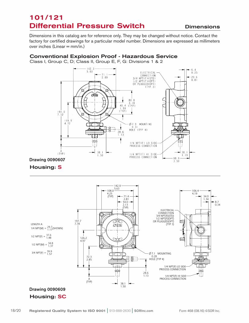
Housing: S
Housing: SC
101/121 Differential Pressure Switch Dimensions
Dimensions in this catalog are for reference only. They may be changed without notice. Contact the factory for certified drawings for a particular model number. Dimensions are expressed as millimeters over inches (Linear = mm/in.)
Conventional Explosion Proof - Hazardous ServiceClass I, Group C, D; Class II, Group E, F, G: Divisions 1 & 2
Drawing 0090607
Drawing 0090609
ISO-9001
14685 W 105TH ST LENEXA, KS 66215 USA913-888-2630SORINC.COM
54.02.13(TYP)
142.95.63
71.42.81
8.70.34
34.01.34
106.44.19
28.61.13
38.11.50
A(TYP)
72.32.85
126.24.97
197.77.78
108.04.25(TYP)
MOUNTING
HOLE (TYP 4)
7.10.28
ELECTRICALCONNECTION
3/4 NPT(F)(STD)1/2 NPT(F)(OPT)
OR PLUGGED(OPT)(TYP 3)
Model Name: 0090609.ASSEM/3/0+
PRODUCT CERTIFICATION DRAWINGALL DIMENSIONS ARE ±1/16 INUNLESS OTHERWISE SPECIFIED
MMLINEAR = IN
DRAWN BY
M SMITHCHECKED BY
J REHMENGINEER APPROVAL
S BOALDATE
3/10/11THIS DRAWING IS THE EXCLUSIVE PROPERTY OF SOR.
NO USE WHATSOEVER OF THE INFORMATION CONTAINEDHEREON, NOR REPRODUCTION IN WHOLE OR PART MAY BE
MADE WITHOUT THE EXPRESS WRITTEN PERMISSION OF SOR.
TITLE
DIM DWG 101/121 SC
EO NUMBER: 5090
SCALE: 0.50
DO NOT SCALE PRINT
DRAWING NUMBER REV
0090609 3
SHEET 1 OF 1DWG SIZE
B
MODEL # SALES ORDER # LINE ITEM # PURCHASE ORDER #
LENGTH A29.71/4 NPT(M) = (SHOWN)1.17
37.61/2 NPT(F) = 1.48
34.8 1/2 NPT(M) = 1.37
39.9 3/4 NPT(F) = 1.57
1/4 NPT(F) HI SIDEPROCESS CONNECTION
1/4 NPT(F) LO SIDEPROCESS CONNECTION
Reset Form
Registered Quality System to ISO 9001 | 913-888-2630 | SORInc.com18/20 Form 468 (08.16) ©SOR Inc.
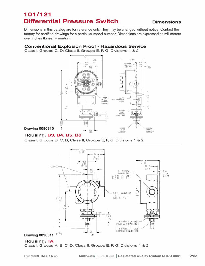
Conventional Explosion Proof - Hazardous ServiceClass I, Groups C, D; Class II, Groups E, F, G: Divisions 1 & 2
Housing: B3, B4, B5, B6Class I, Groups B, C, D; Class II, Groups E, F, G; Divisions 1 & 2
Housing: TAClass I, Groups A, B, C, D; Class II, Groups E, F, G; Divisions 1 & 2
101/121 Differential Pressure Switch Dimensions
Dimensions in this catalog are for reference only. They may be changed without notice. Contact the factory for certified drawings for a particular model number. Dimensions are expressed as millimeters over inches (Linear = mm/in.).
Drawing 0090610
ISO-9001
14685 W 105TH ST LENEXA, KS 66215 USA913-888-2630SORINC.COM
127.15.00
232.29.14
29.71.17TYP
9.50.38
35.31.39
110.34.34
26.61.05
33.41.32
28.61.13
38.11.50
41.21.62
40.01.58
80.03.15
75.12.95
150.15.91
CLEARANCE
FOR 6.40.25
MOUNTINGHARDWARE
1/4 NPTFVENT CONNECTION
LH & RH
ELECTRICALCONNECTION
SEE CHART
Model Name: 0090610.ASSEM/5/0+
PRODUCT CERTIFICATION DRAWINGALL DIMENSIONS ARE ±1/16 INUNLESS OTHERWISE SPECIFIED
MMLINEAR = IN
DRAWN BY
K MITCHELLCHECKED BY
M SMITHENGINEER APPROVAL
S BOALDATE
24 JUN 2011THIS DRAWING IS THE EXCLUSIVE PROPERTY OF SOR.
NO USE WHATSOEVER OF THE INFORMATION CONTAINEDHEREON, NOR REPRODUCTION IN WHOLE OR PART MAY BE
MADE WITHOUT THE EXPRESS WRITTEN PERMISSION OF SOR.
TITLE
DIMENSION DRAWING101/121 B & J
EO NUMBER: 4441
SCALE: 0.69
DO NOT SCALE PRINT
DRAWING NUMBER REV
0090610 5
SHEET 1 OF 1DWG SIZE
B
MODEL # SALES ORDER # LINE ITEM # PURCHASE ORDER #SALES PAGE
HOUSING ELECTRICALCONNECTION
B3 & B63/4 NPTF STD1/2 NPTF OPT
LH & RH
B4 & B5 M20 X 1.5 FLH & RH
J4 3/4 PFFRH ONLY
1/4 NPTFHI SIDE
PROCESSCONNECTION
1/4 NPTFLO SIDE
PROCESSCONNECTION
1/4 NPTMPROCESSCONNECTIONOPTIONAL
1
Reset Form
Drawing 0090611
SORInc.com | 913-888-2630 | Registered Quality System to ISO 9001 19/20Form 468 (08.16) ©SOR Inc.
ISO-9001
14685 W 105TH ST LENEXA, KS 66215 USA913-888-2630SORINC.COM
76.2 MIN3.00
INSTALLATIONCLEARANCE
28.61.13
38.11.50
163.96.45
68.32.69
A2X
LENGTH A
1/4 NPTMSHOWN
29.71.17
1/2 NPTF 37.61.48
1/2 NPTM 34.81.37
3/4 NPTF 39.91.57
Model Name: 0091067.ASSEM/3.1
PRODUCT CERTIFICATION DRAWINGALL DIMENSIONS ARE 1/16 INUNLESS OTHERWISE SPECIFIED
LINEAR = MMIN
DRAWN BY
K MITCHELLCHECKED BY
J REHMENGINEER APPROVAL
S BOALDATE
22 OCT 2015THIS DRAWING IS THE EXCLUSIVE PROPERTY OF SOR.
NO USE WHATSOEVER OF THE INFORMATION CONTAINEDHEREON, NOR REPRODUCTION IN WHOLE OR PART MAY BE
MADE WITHOUT THE EXPRESS WRITTEN PERMISSION OF SOR.
TITLE
DIMENSION DRAWING 101/121 MINI-HERMET AGHOUSING
EO NUMBER: 5309
SCALE: 0.94
DO NOT SCALE PRINT
DRAWING NUMBER REV
0091067 3
SHEET 1 OF 1DWG SIZE
B
MODEL # SALES ORDER # LINE ITEM # PURCHASE ORDER #SALES PAGE
28.71.13 HEX
FACTORY SEALED LEADSCOLOR CODED AND MARKED457.218.00 MINIMUM LENGTH
WEATHERTIGHTCOVER SCREW
FLEXIBLE SEALRETAINER
ELECTRICALCONNECTION
1/2 NPTM
1/4 NPTF HI SIDEPROCESS CONNECTION
1/4 NPTF LO SIDEPROCESS CONNECTION
1
Reset Form
ISO-9001
14685 W 105TH ST LENEXA, KS 66215 USA913-888-2630SORINC.COM
7.10.28
37.41.47
54.72.15
84.93.34
38.11.50
28.61.13
60.52.38
121.04.77
54.02.13
108.04.25
82.33.24
215.98.50
ATYP
Model Name: 0090612.ASSEM/4/2
PRODUCT CERTIFICATION DRAWINGALL DIMENSIONS ARE ±1/16 INUNLESS OTHERWISE SPECIFIED
MMLINEAR = IN
DRAWN BY
K MITCHELLCHECKED BY
M SMITHENGINEER APPROVAL
S BOALDATE
14 SEP 2011THIS DRAWING IS THE EXCLUSIVE PROPERTY OF SOR.
NO USE WHATSOEVER OF THE INFORMATION CONTAINEDHEREON, NOR REPRODUCTION IN WHOLE OR PART MAY BE
MADE WITHOUT THE EXPRESS WRITTEN PERMISSION OF SOR.
TITLE
DIMENSION DRAWING101/121 BA
EO NUMBER: 5095
SCALE: 0.70
DO NOT SCALE PRINT
DRAWING NUMBER REV
0090612 5
SHEET 1 OF 1DWG SIZE
B
MODEL # SALES ORDER # LINE ITEM # PURCHASE ORDER #SALES PAGE
PROCESSCONN SIZE LENGTH A
1/4 NPTMSHOWN
29.71.17
1/2 NPTF 37.61.48
1/2 NPTM 34.81.37
3/4 NPTF 39.91.57
41.6ADD FOR M20 X 1.5 F1.64ELECTRICAL CONNECTION
CLEARANCE
FOR 6.40.25
MOUNTINGHARDWARE
1/4 OR 1/2 NPTMPROCESS CONNECTIONOPTIONAL
ELECTRICALCONNECTION3/4 NPTF STD1/2 NPTF OPT
M20 X 1.5 F OPT
FACTORY SEALED LEADSCOLOR CODED AND MARKED
457.218.00 MINIMUM LENGTH
1/4 NPTF HI SIDEPROCESS CONNECTION
1/4 NPTF LO SIDEPROCESS CONNECTION
1
1
1
Reset Form
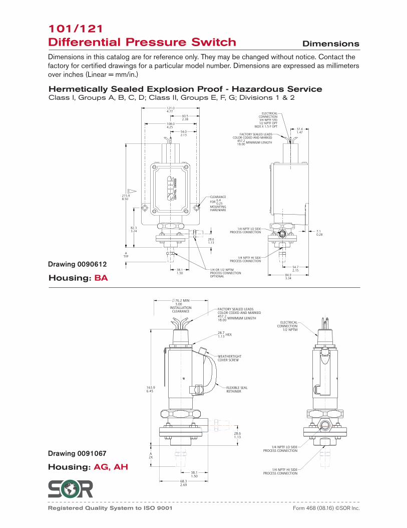
Hermetically Sealed Explosion Proof - Hazardous ServiceClass I, Groups A, B, C, D; Class II, Groups E, F, G; Divisions 1 & 2
Housing: BA
Housing: AG, AH
101/121 Differential Pressure Switch Dimensions
Dimensions in this catalog are for reference only. They may be changed without notice. Contact the factory for certified drawings for a particular model number. Dimensions are expressed as millimeters over inches (Linear = mm/in.)
Drawing 0090612
Drawing 0091067
Registered Quality System to ISO 9001 | 913-888-2630 | SORInc.com20/20 Form 468 (08.16) ©SOR Inc.