Embed Size (px)
Citation preview
Acta Mech 223, 579–591 (2012)DOI 10.1007/s00707-011-0576-x
Naser Sharafkhani · Ghader Rezazadeh · Rasool Shabani
Study of mechanical behavior of circular FGM micro-platesunder nonlinear electrostatic and mechanical shock loadings
Received: 23 May 2011 / Published online: 2 December 2011© Springer-Verlag 2011
Abstract This paper deals with the study of mechanical behavior of a circular functionally graded material(FGM) micro-plate subjected to a nonlinear electrostatic pressure and mechanical shock. It is assumed that theFGM micro-plate is made of metal and ceramic and that material properties are changed continuously along theplate thickness according to a typical function. The nonlinear equation of static deflection and dynamic motionis solved using a step-by-step linearization method and Galerkin-based reduced order model, respectively.In order to find the response of the FGM micro-plate to the electrostatic load and analyze stability of fixedpoints, static deflection, time history and phase portrait for different applied voltages and initial conditionsare illustrated and the effects of different percentages of metal and ceramic constituent on the response of thesystem are investigated. In addition, effects of mechanical shocks characteristics (amplitudes and durations)on the stability of FGM micro-plate are studied.
1 Introduction
Functionally graded materials (FGMs) are new materials made of a mixture of two different materials, usuallymetal and ceramic, and are characterized by continuous variation of properties from one surface to another.FGMs are designed to achieve a functional performance with gradually variable properties in one or moredirections [1]. Due to continuously varying material properties, FGMs have striking advantages over tradi-tional homogeneous materials. For example, FGMs made of ceramic and metal are capable of both resistinga high-temperature environment because of better thermal resistance of the ceramic phase and exhibitingstronger mechanical performance due to the metal phase guaranteeing the structural integrity of FGMs [2].
The concept of FGMs was first considered in Japan in 1984 during a space plane project, thereafter FGMs,due to their specific changing in their material properties, were developed for a wide range of applications, suchas automotive industries, space vehicles, biomedical materials, reactor vessels, military applications, semicon-ductor industry and general structural elements in high thermal environments [3–5], and wide research effortsin many engineering fields during the recent years. Recently, FGMs are widely used in micro and nano-electro-mechanical systems (MEMS and NEMS) [6–10] and also atomic force microscopes (AFMs) [11]. So, analysisof the static and dynamic behavior of FGM structures under different actuation is very important.
Dynamic and static response of the FGM plates to external pressures has been investigated in differentpast researches, for example: Birman [12] provided buckling analysis of functionally graded hybrid composite
N. Sharafkhani · G. Rezazadeh (B) · R. ShabaniMechanical Engineering Department, Urmia University, Urmia, IranE-mail: [email protected].: +98-914-145-1407Fax: +98-441-366-8033
580 N. Sharafkhani et al.
plates, Feldman and Aboudi [13] carried out elastic buckling analysis of FGPs subjected to axial load and alsoinvestigated the optimal spatial distribution of the volume fraction to improve buckling resistance, Praveenand Reddy [14] analyzed the nonlinear static and dynamic response of functionally graded ceramic–metalplates subjected to transverse loads and temperature distribution by using the finite element method, Reddy[15] developed both theoretical and finite element formulations for thick FGM plates according to the higher-order shear deformation plate theory (HSDPT), and studied the nonlinear dynamic response of FGM platessubjected to suddenly applied uniform pressure. Ng et al. [16] studied parametric resonance or dynamicstability of simply supported FGM thin plates under harmonic inplane loading, Yang and Shen [17] pre-sented the dynamic response of initially stressed FGM thin plates, He et al. [18] gave the active control ofdynamic response of FGM plates bonded with piezoelectric actuators, Shen [19] studied the nonlinear bendingresponse of functionally graded plates subjected to transverse loads and in thermal environments, Javaheriand Eslami [20] analyzed the thermal buckling of FGPs based on higher-order theory, Qian et al. [21,22]employed the meshless local Petrov–Galerkin method to analyze free and forced vibrations of a homogeneousFG thick plate based on both the higher-order shear and the normal deformable plate theory of Batra andVidoli [23], Liew et al. [24] carried out static and dynamic piezothermoelastic analysis for the active con-trol of FGPs bonded with integrated piezoelectric sensors and actuators in thermal gradient environments,Woo et al. [25] presented an analytical solution for the post-buckling behavior of moderately thick FGMplates and shells under thermal and mechanical loading, Na and Kim [26] studied the nonlinear bendingresponse of FGPs subjected to uniform pressure and thermal load using a three-dimensional finite elementanalysis, Navazi et al. [27] analyzed the nonlinear cylindrical bending of shear deformable functionally gradedplates under different loadings using analytical methods, Najafizadeh et al. [28] studied an exact solution forbuckling of functionally graded circular plates based on higher-order shear deformation plate theory underuniform radial compression, Sofiyev [29] analyzed the vibration and stability of freely supported FGM trun-cated and complete conical shells subjected to uniform lateral and hydrostatic pressures and, Xia and Shen[30] studied the nonlinear vibration and dynamic response of a shear deformable functionally graded mate-rial (FGM) plate with surface-bonded piezoelectric fiber-reinforced composite actuators (PFRC) in thermalenvironments.
MEMS devices are generally classified according to their actuation mechanisms. The electrostatic actua-tion is one of the most important of them [31]. Study of different systems, which are driven by an electrostaticforce, because of their small size, batch production, low energy consumption, low cost and compatibilitywith integrated circuits (ICs) are very important. These systems are main components of many devices suchas accelerometers [32], micro-actuators [33], micro-resonators [34], switches [35], micro-mirrors [36] andtunable capacitors [37].
With applying a DC voltage to a capacitive MEMS device, attractive electrostatic and elastic restoringforces are created and with increasing voltage, both of them are increased until the applied voltage reachesthe critical value where the elastic restoring force can no longer balance the electrostatic force and pull-inhappens. Static and dynamic pull-in voltages are two different cases of pull-in phenomena that are due tolocal and global bifurcation, respectively. Among the studies dealing with the pull-in phenomena, owing to aelectrostatic actuation, we can refer to a paper of Lin and Zhao [38] in which the pull-in instability of micro-switch actuators is deeply investigated and results for three models (one-dimensional lumped model, linearsupposition model and planar model) are compared. Clamped micro-plates under voltage driving are widelyused in many MEMS devices, too, such as capacitive microphones and micro pumps.
One of the other parameters directly related to MEMS reliability, is shock. Thermal and mechanical arethe two most important shocks that apply to systems and affect their mechanical behavior. Some of the earlystudies in this field have been carried out by Yin and Yue [39], who studied the transient plane strain responsesof multilayered elastic cylinders subjected to axisymmetric impulse, Sadowski et al. [40], who focused on theproblem of temperature field and evaluation of the heat transfer coefficient in FGM cylindrical plates subjectedto thermal shock, and Santos et al. [41] in whose work the study of thermoelastic analysis of functionallygraded cylindrical shells subjected to transient thermal shock loading is carried out.
In this paper, a Galerkin-based step-by-step linearization method (SSLM) and reduced order model havebeen used based on a continuous plate model to investigate the static and dynamic response of MEMS devicesemploying a clamped FGM micro-plate. For five several types of FGM micro-plate that have different per-centages of ceramic, initially, it is focused on the static deflection, natural frequency, stability of equilibriumposition due to static application of a DC voltage and investigating the static pull-in voltage of the system.Next, the dynamic response and pull-in voltage is studied and the effect of shock duration and amplitude onthe response of the system for different states and ceramic constituent percent is depicted.
Study of mechanical behavior of circular FGM micro-plates 581
hgV
Shock
Ground Plate
FGM Micro-Plate
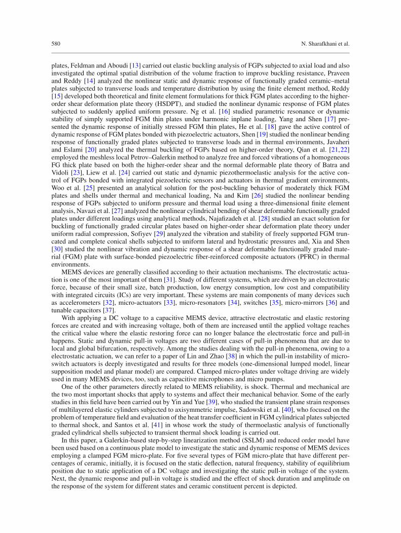
Fig. 1 Schematic view of electrostatically actuated clamped circular FGM micro-plate under mechanical shock
2 Mathematical modeling of clamped circular FGM micro-plate
A clamped circular FGM micro-plate with radius R, thickness h and gap g is shown in Fig. 1, which is subjectedto a mechanical shock and a distributed electrostatic force created by an applied DC voltage.
It is assumed that the properties of the FGM micro-plate are varying continuously along the plate thickness,as follows:
P = (Pm) eβ(|z|) β =(
2
h
)Ln
[Vm (Pm)+ Vc(Pc)
Pm
], (1)
where P is an arbitrary mechanical property of the plate, i.e., Young’s modulus E , density ρ and Poisson’sratio ν; m and c are symbols referring to metal and ceramic, respectively. Vm and Vc are the metal and ceramicvolume fractions, respectively. The Top and bottom surfaces of the micro-plate have the same mixture of metaland ceramic, its middle surface is made from the pure metal, and the ceramic constituent fraction varies throughthe micro-plate thickness from 0 to 100%.
Based on Kirchhoff’s thin plate theory, the relationship between the displacement components along theradial ur , circumferential uθ and transversal direction w can be expressed, as follows:
ur (r, θ, z, t) = −z∂w (r, θ, t)
∂r,
uθ (r, θ, z, t) = −z∂w (r, θ, t)
r∂θ,
w (r, θ, z, t) = w (r, θ, t) . (2)
According to Eq. (2), the strain components can be achieved as:
εr = ∂ur
∂r= −z
∂2w
∂r2 ,
εθ = ur
r+ 1
r
∂uθ∂θ
= −z
(∂w
r∂r+ 1
r2
∂2w
∂θ2
),
γrθ = 1
r
∂ur
∂θ+ ∂uθ∂r
− uθr
= −2z∂
∂r
(1
r
∂w
∂θ
). (3)
According to Hooke’s law, the stress-strain relations for a plate in the cylindrical coordinate system can beexpressed as the following [42]: ⎡
⎣σrσθτrθ
⎤⎦ =
⎡⎣
E1−ν2
νE1−ν2 0
νE1−ν2
E1−ν2 0
0 0 G
⎤⎦
⎡⎣ εrεθγrθ
⎤⎦ . (4)
Substituting Eq. (3) into Eq. (4) leads to the following stress components:
σr = −E(1 − ν2
)(
z∂2w
∂r2 + νz
(1
r2
∂2w
∂θ2 + ∂w
r∂r
)),
σθ = −E(1 − ν2
)(
zν∂2w
∂r2 + z
(1
r2
∂2w
∂θ2 + ∂w
r∂r
)),
τrθ = Gγrθ = −2Gz∂
∂r
(1
r
∂w
∂θ
). (5)
582 N. Sharafkhani et al.
Bending and twisting moments can be calculated as follows:
Mr =h2∫
− h2
σr zdz, Mθ =h2∫
− h2
σθ zdz, Mrθ =h2∫
− h2
τrθ zdz. (6)
The equation of transverse motion of a circular micro-plate is [43]:
∂2 Mr
∂r2 + 2
r
∂Mr
∂r+ 2
r
∂2 Mrθ
∂r∂θ− 1
r
∂Mθ
∂r+ 2
r2
∂Mrθ
∂θ+ 1
r2
∂2 Mθ
∂θ2 + f = ρh∂2w
∂t2 , (7)
where f is an external force. Assuming the deflection of the clamped circular micro-plate is axisymmetric(∂w∂θ
= 0, τrθ = 0, Mrθ = 0)
and substituting Eq. (5) into Eq. (7), the equation of transverse motion for acircular FGM micro-plate subjected to a nonlinear electrostatic force takes the following form:
DFGM(∇4w
) + ρFGMh∂2w
∂t2 = f,
DFGM =h2∫
− h2
(Ez)
(1 − ν2)zdz, ρFGM =
∫ h2
− h2ρdz
h, f = ε0V 2
2(g − w)2, (8)
where ε0 is the permittivity of the air within gap, g is the initial gap between the FGM micro-plate and sub-strate, V is the applied DC voltage and ∇4 is the biharmonic operator in the polar coordinate system for theaxisymmetric circular plate:
∇4 = ∂4
∂r4 + 2
r
∂3
∂r3 − 1
r2
∂2
∂r2 + 1
r3
∂
∂r. (9)
Denoting the acceleration of a mechanical shock by A, the governing equation of motion for the transversemotion of the micro-plate including shock effects can be written as:
DFGM[∇4w
] + ρFGMh
(∂2w
∂t2 − A
)= ε0V 2
2(g − w)2. (10)
Acceleration of the package is assumed to be in the form A = aS (t) in which a and S (t) are the amplitudeand shape of the acceleration, respectively. The clamped micro-plate’s boundary conditions are given by
∂w
∂r(R, t) = 0, w (R, t) = 0. (11)
For convenience, the following nondimensional parameters are defined to transform Eq. (10) into nondimen-sional form:
w = w
g, r = r
R, t = t
t∗,
t∗ = R2
(√hρFGM
Dm
), Dm = Emh3
12(1 − ν2
m
) , (12)
Substituting Eq. (12) into Eq. (10), the nondimensional equation of transverse motion takes the following form:
(α1)[∇4w
] +(∂2w
∂ t2
)= (α2)
V 2
(1 − w
)2 + α3sh(t),
α1 =∫ h
2
− h2
Ez2
(1−ν2)dz
Dm, α2 = (ε0)
(R4
)2 (Dm)
(g3
) , α3 = (hρFGM)a(R4
)(Dm) (g)
. (13)
Study of mechanical behavior of circular FGM micro-plates 583
3 Numerical solution
3.1 Static analysis
Because of the nonlinearity of the electrostatic force and the complexity of obtaining an exact solution, astep-by-step linearization method (SSLM) [33] is used to linearize the equation of static deflection:
L (ws, V
) = (α1)∇4ws − (α2)
(V
1 − ws
)2
= 0. (14)
The SSLM is performed by introducing wks as the displacement of the micro-plate due to the voltage V k
applied in the (k)th step. To move forward to the next step, voltage is increased to a new valueV k+1, and thedisplacement will be changed to wk+1
s . The increase in the transverse displacement is denoted by ψ(r):
V k+1 = V k + δV,
wk+1s = wk
s + δws = wks + ψ(r). (15)
Therefore, Eq. (14) for the (k + 1)th step can be rewritten as follows:
L(wk+1
s , V k+1)
= (α1)∇4wk+1s − (α2)
(V k+1
1 − wk+1s
)2
= 0. (16)
Considering a small value of δV , the value of ψ(r) will be expected to be small enough to obtain a desiredaccuracy. Using the calculus of variation theory and considering first two terms of the Taylor‘s expansion, wecan obtain the following linearized equation to calculate ψ :
L (ψ) = (α1)∇4ψ − 2(α2)
[ (V k
)2
(1 − wk
s
)3ψ + V k
(1 − wk
s
)2 δV
]= 0. (17)
The unknown ψ(r) based on a function space can be expressed in terms of base functions as following:
ψ(r) =
∞∑j=1
a jϕ j (r), (18)
where ϕ j are the base or shape functions, which satisfy the accompanying boundary conditions. The ψ(r)
can be approximated by truncating the summation series to a finite number n:
ψ(r) ∼= ψn
(r) =
n∑j=1
a jϕ j (r). (19)
By substituting Eq. (19) into Eq. (17), and multiplying by ϕi (r) as the weight function in the Galerkin-basedweighted residual method, and integrating the outcome over r = 0 to 1, a set of algebraic equations will beobtained. By solving them, the deflection at any given applied voltage can be determined.
3.2 Dynamic analysis
To study the response of the clamped circular FGM micro-plate to a dynamic load, a Galerkin-based reducedorder model can be used [44]. In this case, the equation of dynamic motion (13) is rewritten in the followingform:
(α1)(∇4w
) +(∂2w
∂ t2
)= (α2)
V 2
(1 − w)2+ α3sh
(t) = F
(V, w, g, A
). (20)
Because of the nonlinearity of the electrostatic force, direct application of the Galerkin method is very com-plicated, therefore the nonlinear term is considered as a forcing term and integration over this term is repeated
584 N. Sharafkhani et al.
at each time step. By selecting small enough time steps, this assumption leads to an accurate enough result.To achieve a reduced order model w
(r , t
), can be approximated as
w(r , t
) ∼= wn(r , t
) =n∑
j=1
q j(t)ϕ j (r), (21)
where q j(t)
are the generalized coordinates and ϕ j (r) are the shape functions. By substituting Eq. (21) intoEq. (20) and multiplying by ϕi (r) as the weight function in the Galerkin method, and integrating the outcomeover r = 0 to 1, a Galerkin-based reduced order model is generated as
n∑j=1
Mi j q j(t) + (α1)
n∑j=1
Ki j q j(t) = Fi , (22)
where M, K are the mass and stiffness matrices, respectively, and F introduces the forcing vector. The elementof the M, K and F are calculated as follows:
Ki j = 1∫0ϕi
(∇4ϕ j)
rdr , Fi = 1∫0ϕi F
(V, w, g, A
)rdr , Mi j = 1∫
0
(ϕiϕ j
)rdr . (23)
By solving Eq. (23), the response of the micro-plate can be determined at any time.
4 Numerical results and discussion
For comparison of the obtained results with the results existing in references, since there are no experimental ortheoretical results for FGM micro-plates, a simple and homogeneous micro-plate is used. The considered sim-ple micro-plate properties are E = 169 Gpa, v = 0.3, h = 20μm, R = 250μm, g = 1μm. The calculatedpull-in voltage for δV = 0.05 v is 318.4 v, which has a good agreement with those reported in [45].
In order to study the clamped FGM micro-plate, we consider a case with the geometrical and materialproperties as listed in Tables 1 and 2, respectively.
Based on the ceramic constituent fraction of the top and bottom surfaces, five different types of FGMmicro-plates (Vc = 0, 25, 50, 75 and 100%) are investigated. The first type is indeed a simple and homoge-neous classic micro-plate from pure metal, and for 5th type, the middle surface is made from pure metal andthe top and bottom surfaces are pure ceramic.
It is noted that the bottom surface of the micro-plate should be conductive as an electrode for creatingelectrostatic pressure, thus the bottom surface of the micro-plate can be covered with a golden thin layer.
Table 1 Geometrical properties of the FGM micro-plate
Parameters Values
Radius (R) 250 μmThickness of the (h) 2 μmPermittivity of air (ε0) 8.85 pF/mInitial gap (g) 1.5μm
Table 2 Material properties of the FGM micro-plate
Parameters Values
Metal Ceramic
Material type Steel AluminaYoung’s modulus (E) 210 Gpa 390 GpaPoisson’s ratio (ν) 0.29 0.24Density (ρ) 7, 850 kg/m3 3, 940 kg/m3
Study of mechanical behavior of circular FGM micro-plates 585
4.1 Stability of equilibrium position due to static application of a DC voltage
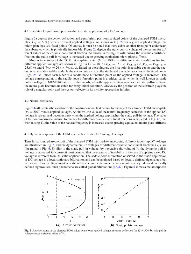
Figure 2a depicts the center deflection and equilibrium positions or fixed points of the clamped FGM micro-plate (Vc = 50%) versus different applied voltages. As shown in Fig. 2a for a given applied voltage, themicro-plate has two fixed points. Of course, it must be noted that there exists another fixed point underneaththe substrate, which is physically impossible. Figure 2b depicts the static pull-in voltage of the system for dif-ferent values of the ceramic constituent fraction. As shown in this figure with raising the ceramic constituentfraction, the static pull-in voltage is increased due to growing equivalent micro-plate stiffness.
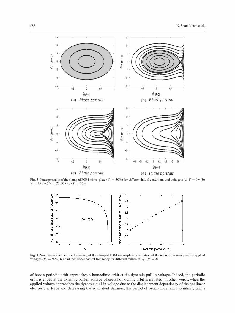
Motion trajectories of the FGM micro-plate center (Vc = 50%) for different initial conditions for fourdifferent applied voltages are shown in Fig. 3a (V = 0), b (VDC = 15v < VPull−in), c (VDC = VPull−in =23.60 v) and d (VDC = 26 v > VPull−in). Based on these figures, the first point is a stable center and the sec-ond is an unstable saddle node. In the state-control space, the stable and unstable branches of the fixed points(Figs. 2a, 3c), meet each other at a saddle-node bifurcation point as the applied voltage is increased. Thevoltage corresponding to the saddle node bifurcation point is a critical value, which is well known as staticpull-in voltage, in MEMS literature. In other words, when the applied voltage reaches the static pull-in voltage,the micro-plate becomes unstable for every initial condition. Obviously the position of the substrate plays therole of a singular point and the system velocity in its vicinity approaches infinity.
4.2 Natural frequency
Figure 4a illustrates the variation of the nondimensional first natural frequency of the clamped FGM micro-plate(Vc = 50%) versus applied voltages. As shown, the value of the natural frequency decreases as the applied DCvoltage is raised, and becomes zero when the applied voltage approaches the static pull-in voltage. The valueof the nondimensional natural frequency for different ceramic constituent fractions is depicted in Fig. 4b, thatwith raising Vc, the value of the natural frequency is increased due to growing equivalent micro-plate stiffness.
4.3 Dynamic response of the FGM micro-plate to step DC voltage loadings
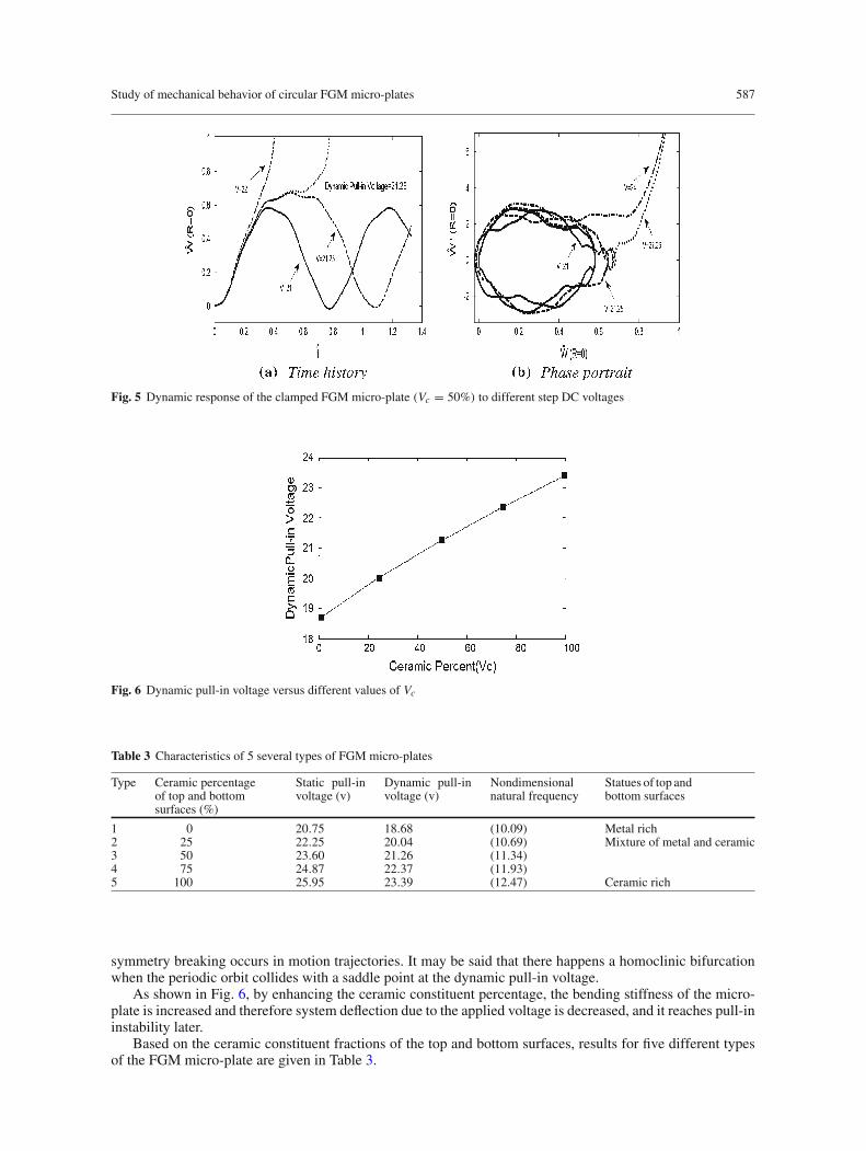
Time history and phase portrait of the clamped FGM micro-plate undergoing different input step DC voltagesare illustrated in Fig. 5, and the dynamic pull-in voltages for different ceramic constituent fractions (Vc), areillustrated in Fig. 6. Similar to the static pull-in voltage, by increasing the value of Vc the dynamic pull-involtage is increased. Of course, it must be noted that the scenario of instability in the case of applying a step DCvoltage is different from its static application. The saddle node bifurcation observed in the static applicationof DC voltage is a local stationary bifurcation and can be analyzed based on locally defined eigenvalues, butin the case of step voltage input periodic orbits encounter phenomena that cannot be analyzed based on locallydefined eigenvalues. Such phenomena are called global bifurcations [46,47]. Figure 5 shows a metamorphosis
Fig. 2 Static response of the clamped FGM micro-plate to an applied voltage: a center deflection for Vc = 50% b static pull-involtage versus different values of Vc
586 N. Sharafkhani et al.
Fig. 3 Phase portraits of the clamped FGM micro-plate (Vc = 50%) for different initial conditions and voltages: (a) V = 0 v (b)V = 15 v (c) V = 23.60 v (d) V = 26 v
Fig. 4 Nondimensional natural frequency of the clamped FGM micro-plate: a variation of the natural frequency versus appliedvoltages (Vc = 50%) b nondimensional natural frequency for different values of Vc, (V = 0)
of how a periodic orbit approaches a homoclinic orbit at the dynamic pull-in voltage. Indeed, the periodicorbit is ended at the dynamic pull-in voltage where a homoclinic orbit is initiated, in other words, when theapplied voltage approaches the dynamic pull-in voltage due to the displacement dependency of the nonlinearelectrostatic force and decreasing the equivalent stiffness, the period of oscillations tends to infinity and a
Study of mechanical behavior of circular FGM micro-plates 587
Fig. 5 Dynamic response of the clamped FGM micro-plate (Vc = 50%) to different step DC voltages
Fig. 6 Dynamic pull-in voltage versus different values of Vc
Table 3 Characteristics of 5 several types of FGM micro-plates
Type Ceramic percentageof top and bottomsurfaces (%)
Static pull-involtage (v)
Dynamic pull-involtage (v)
Nondimensionalnatural frequency
Statues of top andbottom surfaces
1 0 20.75 18.68 (10.09) Metal rich2 25 22.25 20.04 (10.69) Mixture of metal and ceramic3 50 23.60 21.26 (11.34)4 75 24.87 22.37 (11.93)5 100 25.95 23.39 (12.47) Ceramic rich
symmetry breaking occurs in motion trajectories. It may be said that there happens a homoclinic bifurcationwhen the periodic orbit collides with a saddle point at the dynamic pull-in voltage.
As shown in Fig. 6, by enhancing the ceramic constituent percentage, the bending stiffness of the micro-plate is increased and therefore system deflection due to the applied voltage is decreased, and it reaches pull-ininstability later.
Based on the ceramic constituent fractions of the top and bottom surfaces, results for five different typesof the FGM micro-plate are given in Table 3.
588 N. Sharafkhani et al.
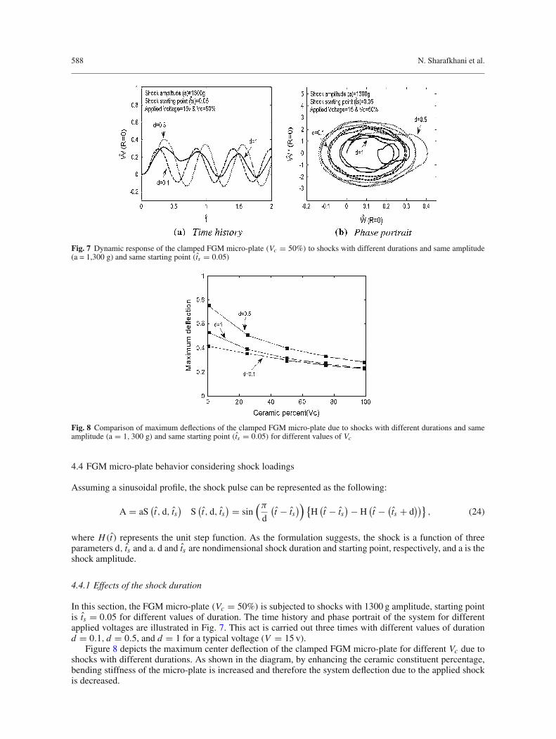
Fig. 7 Dynamic response of the clamped FGM micro-plate (Vc = 50%) to shocks with different durations and same amplitude(a = 1,300 g) and same starting point (ts = 0.05)
Fig. 8 Comparison of maximum deflections of the clamped FGM micro-plate due to shocks with different durations and sameamplitude (a = 1, 300 g) and same starting point (ts = 0.05) for different values of Vc
4.4 FGM micro-plate behavior considering shock loadings
Assuming a sinusoidal profile, the shock pulse can be represented as the following:
A = aS(t, d, ts
)S
(t, d, ts
) = sin(π
d
(t − ts
)) {H
(t − ts
) − H(t − (
ts + d))}
, (24)
where H(t) represents the unit step function. As the formulation suggests, the shock is a function of threeparameters d, ts and a. d and ts are nondimensional shock duration and starting point, respectively, and a is theshock amplitude.
4.4.1 Effects of the shock duration
In this section, the FGM micro-plate (Vc = 50%) is subjected to shocks with 1300 g amplitude, starting pointis ts = 0.05 for different values of duration. The time history and phase portrait of the system for differentapplied voltages are illustrated in Fig. 7. This act is carried out three times with different values of durationd = 0.1, d = 0.5, and d = 1 for a typical voltage (V = 15 v).
Figure 8 depicts the maximum center deflection of the clamped FGM micro-plate for different Vc due toshocks with different durations. As shown in the diagram, by enhancing the ceramic constituent percentage,bending stiffness of the micro-plate is increased and therefore the system deflection due to the applied shockis decreased.
Study of mechanical behavior of circular FGM micro-plates 589
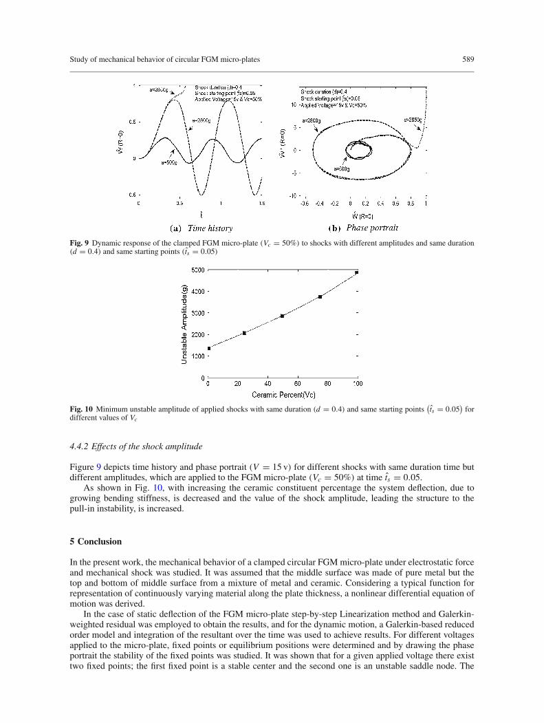
Fig. 9 Dynamic response of the clamped FGM micro-plate (Vc = 50%) to shocks with different amplitudes and same duration(d = 0.4) and same starting points (ts = 0.05)
Fig. 10 Minimum unstable amplitude of applied shocks with same duration (d = 0.4) and same starting points(ts = 0.05
)for
different values of Vc
4.4.2 Effects of the shock amplitude
Figure 9 depicts time history and phase portrait (V = 15 v) for different shocks with same duration time butdifferent amplitudes, which are applied to the FGM micro-plate (Vc = 50%) at time ts = 0.05.
As shown in Fig. 10, with increasing the ceramic constituent percentage the system deflection, due togrowing bending stiffness, is decreased and the value of the shock amplitude, leading the structure to thepull-in instability, is increased.
5 Conclusion
In the present work, the mechanical behavior of a clamped circular FGM micro-plate under electrostatic forceand mechanical shock was studied. It was assumed that the middle surface was made of pure metal but thetop and bottom of middle surface from a mixture of metal and ceramic. Considering a typical function forrepresentation of continuously varying material along the plate thickness, a nonlinear differential equation ofmotion was derived.
In the case of static deflection of the FGM micro-plate step-by-step Linearization method and Galerkin-weighted residual was employed to obtain the results, and for the dynamic motion, a Galerkin-based reducedorder model and integration of the resultant over the time was used to achieve results. For different voltagesapplied to the micro-plate, fixed points or equilibrium positions were determined and by drawing the phaseportrait the stability of the fixed points was studied. It was shown that for a given applied voltage there existtwo fixed points; the first fixed point is a stable center and the second one is an unstable saddle node. The
590 N. Sharafkhani et al.
pull-in voltages of the structure in the cases of the static and dynamic actuating by an applied DC voltagewere calculated. The effect of different shock durations on the pull-in instability of the FGM micro-plate wasstudied and time histories and phase portraits for different material volume fractions were shown. It was shownthat when the duration of the shock was set close to the natural period of the system and shock amplitudeshave more than a specific value, that can render the structure behavior unstable at a lower applied voltage thanthe dynamic pull-in voltage. The results of the aforementioned parameters on the behavior of the micro-plateare recommended to be taken into consideration in the designing process of microelectromechanical systems,so that occurrence of mechanical shocks would not cause undesired instability and possible failure.
References
1. Koizumi, M.: The concept of FGM. In: Proceedings of the Second International Symposium on Functionally GradientMaterials at the Third International Ceramic Science and Technology Congress (1992)
2. Suresh, S.: Modeling and design of multi-layered and graded materials. Prog. Mater. Sci. 42, 243–251 (1997)3. Bhangale, R.K., Ganesan, N., Padmanabhan, C.: Linear thermoelastic buckling and free vibration behavior of functionally
graded truncated conical shells. J. Sound Vib. 292, 341–371 (2006)4. Bian, Z.G., Lim, C.W., Chen, W.Q.: On functionally graded bems with integrates surface piezoelectric layers. Compos.
Struct. 72, 339–351 (2006)5. Simesk, M.: Fundamental frequency analysis of functionally graded beams by using different higher-order beam theo-
ries. Nucl. Eng. Des. 240, 697–705 (2010)6. Fu, Y.Q., Du, H.J., Huang, W.M., Zhang, S., Hu, M.: TiNi-based thin films in MEMS applications: a review. Sens. Actuators
A 112, 395–408 (2004)7. Witvrouw, A., Mehta, A.: The use of functionally graded poly-SiGe layers for MEMS applications. Funct. Grad. Mater.
VIII 492-493, 255–260 (2005)8. Lee, Z., Ophus, C., Fischer, L.M., Nelson-Fitzpatrick, N., Westra, K.L., Evoy, S. et al.: Metallic NEMS components fabricated
from nanocomposite Al–Mo films. Nanotechnology 17, 3063–3070 (2006)9. Ke, L.-L., Yang, J., Kitipornchi, I. Sr.: Nonlinear free vibration of functionally graded carbon nanotube-reinforced composite
beams. Compos. Struct. 92, 676–683 (2010)10. Mohammadi-Alasti, B., Rezazadeh, G., Borgheei, A., Minaei, S., Habibifar, R.: On the mechanical behavior of a function-
ally graded micro-beam subjected to a thermal moment and nonlinear electrostatic pressure. Compos. Struct. 93, 1516–1525 (2011)
11. Rahaeifard, M., Kahrobaiyan, M., Ahmadian, M.: Sensitivity analysis of atomic force microscope cantilever made of func-tionally graded materials. In: DETC2009-86254, 3rd International Conference on Micro- and Nanosystems (MNS3) SanDiego, CA, USA (2009)
12. Birman, V.: Buckling of functionally graded hybrid composite plates. Proceedings of the 10th conference on engineeringmechanics 2, 1199–1292 (1995)
13. Feldman, E., Aboudi, J.: Buckling analysis of functionally graded plates subjected to uniaxial loading. Compos.Struct. 38, 29–36 (1997)
14. Praveen, G.N., Reddy, J.N.: Nonlinear transient thermoelastic analysis of functionally graded ceramic–metal plates. Int.J. Solids Struct. 35, 4457–4476 (1998)
15. Reddy, J.N.: Analysis of functionally graded plates. Int. J. Numer. Method. Eng. 47, 663–684 (2000)16. Ng, T.Y., Lam, K.Y., Liew, K.M.: Effects of FGM materials on the parametric resonance of plate structures. Comput. Method.
Appl. Mech. Eng. 190, 953–962 (2000)17. Yang, J., Shen, H.S.: Dynamic response of initially stressed functionally graded rectangular thin plates. Compos.
Struct. 54, 497–508 (2001)18. He, X.Q., Ng, T.Y., Sivashanker, S., Liew, K.M.: Active control of FGM plates with integrated piezoelectric sensors and
actuators. Int. J. Solids Struct. 38, 1641–1655 (2001)19. Shen, H.-S.: Nonlinear bending response of functionally graded plates subjected to transverse loads and in thermal environ-
ments. Int. J. Mech. Sci. 44, 561–584 (2002)20. Javaheri, R., Eslami, M.R.: Thermal buckling of functionally graded plates based on higher order theory. J. Therm.
Stress. 25, 603–625 (2002)21. Qian, L.F., Batra, R.C., Chen, L.M.: Free and forced vibrations of thick rectangular plates by using higher-order shear and
normal deformable plate theory and meshless local Petrov–Galerkin (MLPG). Comput. Model. Eng. Sci. 4, 519–534 (2003)22. Qian, L.F., Batra, R.C., Chen, L.M.: Elastostatic deformations of thick plate by using higher-order shear and normal deform-
able plate theory and two meshless local Petrov–Galerkin (MLPG) methods. Comput. Model. Eng. Sci. 4, 161–176 (2003)23. Batra, R.C., Vidoli, S., Vestroni, S.: Plane waves and modal analysis in higher-order shear and normal deformable plate
theories. J. Sound Vib. 257, 63–88 (2002)24. Liew, K.M., He, X.Q., Ng, T.Y., Kitipornchai, S.: Finite element piezothermoelasticity analysis and the active control of
FGM plates with integrated piezoelectric sensors and actuators. Comput. Mech. 31, 350–358 (2003)25. Woo, J., Merguid, S.A., Stranart, J.C., Liew, K.M.: Thermomechanical postbuckling analysis of moderately thick functionally
graded plates and shallow shells. Int. J. Mech. Sci. 47, 1147–1171 (2005)26. Na, K.S., Kim, J.H.: Nonlinear bending response of functionally graded plates under thermal loads. J. Therm. Stress. 29,
245–261 (2006)27. Navazi, H.M., Haddadpour, H.: Nonlinear cylindrical bending analysis of shear deformable functionally graded plates under
different loadings using analytical methods. Int. J. Mech. Sci. 50, 1650–1657 (2008)
Study of mechanical behavior of circular FGM micro-plates 591
28. Najafizadeh, M.M., Heydari, H.R.: An exact solution for buckling of functionally graded circular plates based on higherorder shear deformation plate theory under uniform radial compression. Int. J. Mech. Sci. 50, 603–612 (2008)
29. Sofiyev, A.H.: The vibration and stability behavior of freely supported FGM conical shells subjected to external pres-sure. Compos. Struct. 89, 356–366 (2009)
30. Xia, X.-K., Shen, H.-S.: Nonlinear vibration and dynamic response of FGM plates with piezoelectricfiber reinforced com-posite actuators. Compos. Struct. 90, 254–262 (2009)
31. Senturia, S.: Microsystem Design. Kluwer, Norwell, MA (2001)32. Bao, M., Wang, W.: Future of microelectromechanical systems (MEMS). Sens. Actuators A: Phys. 56, 135–141 (1996)33. Rezazadeh, G., Tahmasebi, A., Zubtov, M.: Application of piezoelectric layers in electrostatic MEM actuators: controlling
of pull-in voltage. Microsyst. Technol. 12, 1163–1170 (2006)34. Sazonova, V.: A tunable carbon nanotube resonator. Ph.D Thesis, Cornell University (2006)35. Sadeghian, H., Rezazadeh, G., Osterberg, P.: Application of the generalized different quadrature method to the study of
pull-in phenomena of MEMS switches. J. Microelectromech. Syst. 16, 1334–1340 (2007)36. Rezazadeh, G., Khatami, F., Tahmasebi, A.: Investigation of the torsion and bending effect on static stability of electrostatic
torsional micromirrors. Microsyst. Technol. 13, 715–722 (2007)37. Mehdaoui, A., Pisani, M., Tsamados, D., Casset, F., Ancey, P., Ionescu, A.M.: MEMS tunable capacitors with fragmented
electrodes and rotational electro-thermal drive. Microsyst. Technol. 13, 1589–1594 (2007)38. Lin, W.-H., Zhao, Y.-P.: Pull-in instability of micro-switch actuators: model review. Int. J. Nonlinear Sci. Numer.
Simul. 9, 175–183 (2008)39. Yin, X.C., Yue, Q.Z.Q.: Transient plane-strain response of multilayered elastic cylinders to axisymmetric impulse. J. Appl.
Mech. 69, 825–835 (2002)40. Sadowski, T., Boniecki, M., Librant, Z., Nakonieczny, K.: Theoretical prediction and experimental verification of temperature
distribution in FGM cylindrical plates subjected to thermal shock. Int. J. Heat Mass Transf. 50, 4461–4467 (2007)41. Santos, H., Mota Soares, C.M., Mota Soares, C.A., Reddy, J.N.: A semi-analytical finite element model for the analysis of
cylindrical shells made of functionally graded materials under thermal shock. Compos. Struct. 86, 10–21 (2008)42. Weisa, A.W.: Vibration of Plates. National Aeronautics and Space Administration, Washington, D.C (1969)43. Agensov, L.G., Sachenkov, A.V.: The stability and vibration of circular conical and cylindrical shells at different boundary
conditions. Res. Theory Plates Shells, Kazan State University, Kazan 2, 111–126 (1964)44. Vogol, G.W., Nayfeh, A.H.: A reduced-order model for electrically actuated clamped circular plates. J. Micromech. Micro-
eng. 15, 684 (2005). doi:10.1088/0960-1317/15/4/00245. Nabian, A., Rezazadeh, G., Haddad-darafshi, M., Tahmasbi, A.: Mechanical behavior of a circular micro plate subjected to
uniform hydrostatic and non-uniform electrostatic pressure. Microsyst. Technol. 14, 235–240 (2007)46. Seydel, R.: Practical Bifurcation and Stability Analysis, 3rd edn. Springer, Berlin (2010). doi:10.1007/978-1-4419-1740-947. Kuznetsov, Y.A.: Elements of Applied Bifurcation Theory. 2nd edn. Springer, New York (1997)