Embed Size (px)
Citation preview

11/14/2007 K. T. IEEE 802 Plenary MeetingHigh Speed Study Group, Atlanta, GA 1
100 G Active Optics Cables
IEEE 802 Plenary MeetingHigh Speed Study Group
Atlanta, GeorgiaNovember 14th, 2007
Karim TatahCray Inc.
11/14/2007 K. T. IEEE 802 Plenary MeetingHigh Speed Study Group, Atlanta, GA 2
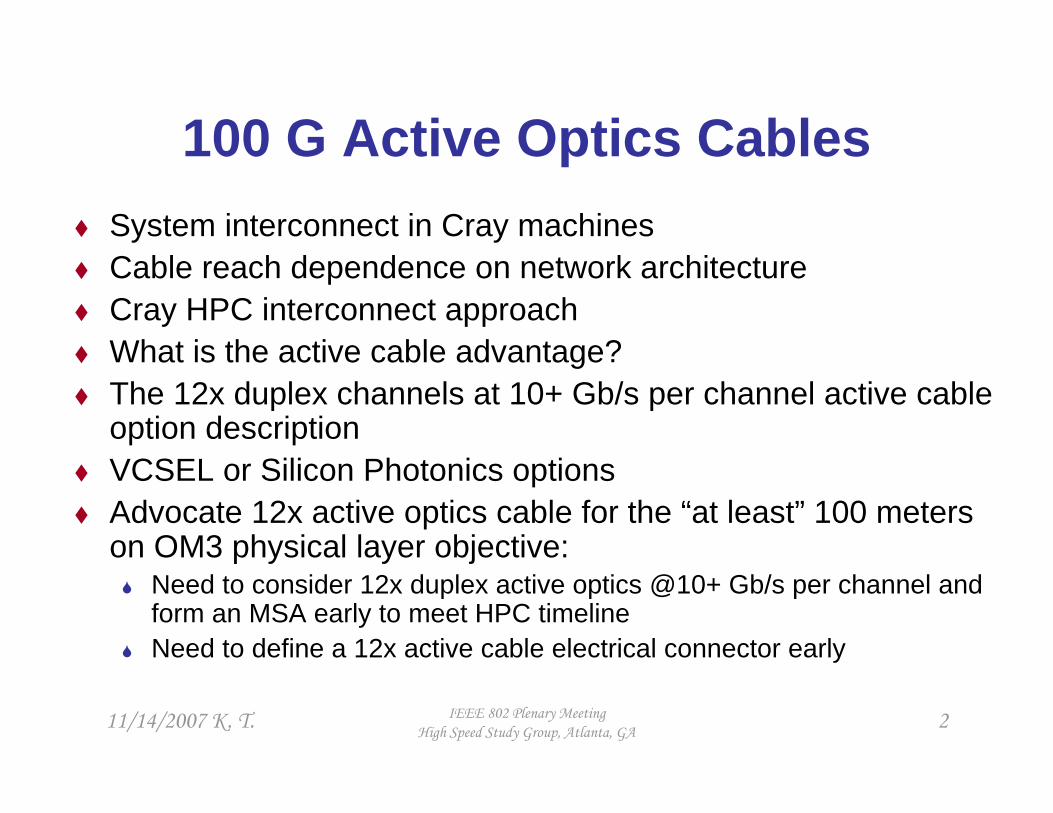
100 G Active Optics CablesSystem interconnect in Cray machinesCable reach dependence on network architectureCray HPC interconnect approachWhat is the active cable advantage? The 12x duplex channels at 10+ Gb/s per channel active cable option descriptionVCSEL or Silicon Photonics optionsAdvocate 12x active optics cable for the “at least” 100 meters on OM3 physical layer objective:
Need to consider 12x duplex active optics @10+ Gb/s per channel and form an MSA early to meet HPC timelineNeed to define a 12x active cable electrical connector early
11/14/2007 K. T. IEEE 802 Plenary MeetingHigh Speed Study Group, Atlanta, GA 3
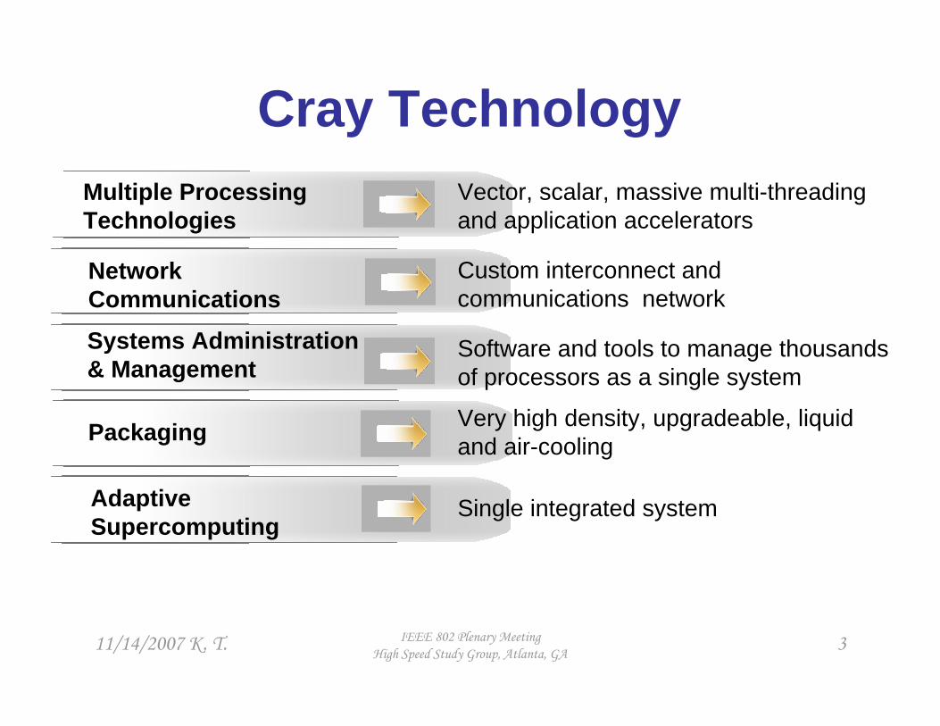
Custom interconnect and communications network
Network Communications
Software and tools to manage thousands of processors as a single system
Systems Administration& Management
Single integrated systemAdaptive Supercomputing
Very high density, upgradeable, liquid and air-coolingPackaging
Vector, scalar, massive multi-threading and application accelerators
Multiple ProcessingTechnologies
Cray Technology

11/14/2007 K. T. IEEE 802 Plenary MeetingHigh Speed Study Group, Atlanta, GA 4
Cray System Network Bandwidth: Examples
An example of large bandwidth system XT3/XT4 scalar system:
Processing: ~ 100 TFLOPBandwidth: 48 duplex channels
x 3.125 Gb/s = 150 Gb/s per point-to-point cable link
An example of large bandwidth system XT5/XT5h vector-scalar hybrid system:
Performance: ~ 20 GFLOP per nodeBandwidth: 24 duplex channels x 5 Gb/s
= 120 Gb/s per point-to-point cable link

11/14/2007 K. T. IEEE 802 Plenary MeetingHigh Speed Study Group, Atlanta, GA 5
☺
☺☺
☺☺☺
☺☺☺☺
Cost
☺☺☺☺
☺☺☺☺
☺☺
☺
Latency or Hops
20
40
8
7
~ Max Cable Reach
(m)
☺☺☺☺
☺☺☺
☺☺
☺
Bandwidth
Butterfly
Network Graph
Torus(XT3 and XT4 )
Fat Tree or Folded Clos
(XT5)
Hypercube
P P
RRRRRRRR
P P
RRRRRRRR
P P
RRRRRRRR
P P
RRRR
150 1 2
R R R RR R R RR R R R
RRRR
R R R R
A Simplified View of Supercomputing Networks

11/14/2007 K. T. IEEE 802 Plenary MeetingHigh Speed Study Group, Atlanta, GA 6
Links Speeds and FeedsGEthernet (GE), InfiniBand (IB), and Fibre Channel (FC) and Cray’s point-to-point network links bandwidth
120G-Potter (XT5)
24x
16 G FC
8x
100 GE25
120G-IB120-FC
100 GE40 GE40 G-IB40 FC
10 GE10
8G-FC8
60 G-IB20 G-IB5
150G-Sea star (XT4)
3.125
4G-FC4
8 G FC2
30 G-IB
12x10x 48x
25G6.25
10 GE10 G-IB
2.5
4x 1x Channel (#)Rate (Gb/s)

11/14/2007 K. T. IEEE 802 Plenary MeetingHigh Speed Study Group, Atlanta, GA 7

11/14/2007 K. T. IEEE 802 Plenary MeetingHigh Speed Study Group, Atlanta, GA 8
Cray HPC Interconnect Approach
Adapt off-the-shelf optics at 12 x10 or 12x 12.5 Gb/s for 2010 system product.
Customize channel density and push for 12.5 Gb/s Active Cables.
Modify network architecture in order to maintain global bandwidth.
11/14/2007 K. T. IEEE 802 Plenary MeetingHigh Speed Study Group, Atlanta, GA 9
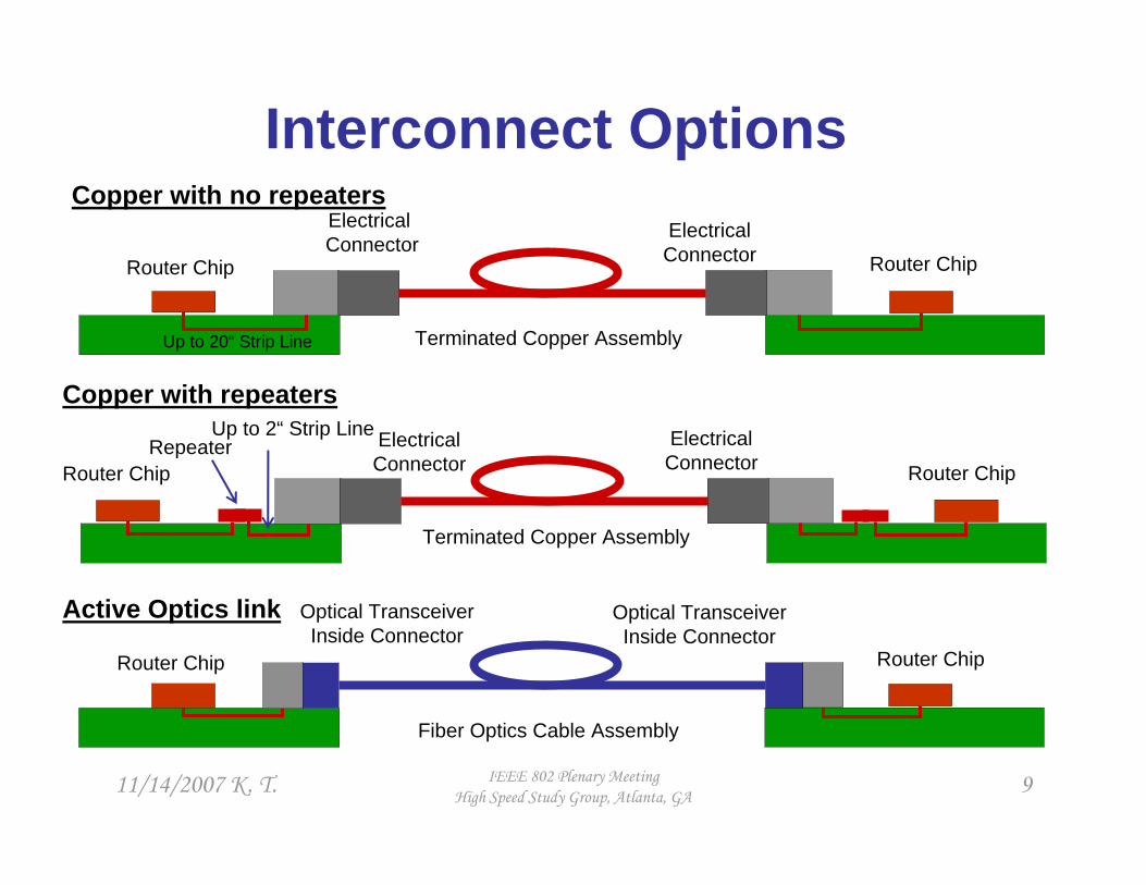
Interconnect Options
Router Chip Router Chip
Terminated Copper Assembly
Electrical Connector
Electrical Connector
Up to 20“ Strip Line
Optical TransceiverInside Connector
Copper with no repeaters
Copper with repeaters
Active Optics link
Repeater Electrical Connector
Electrical Connector
Up to 2“ Strip Line
Terminated Copper Assembly
Router Chip Router Chip
Fiber Optics Cable Assembly
Router Chip Router Chip
Optical TransceiverInside Connector

11/14/2007 K. T. IEEE 802 Plenary MeetingHigh Speed Study Group, Atlanta, GA 10
Active Optics link
Optical TransceiverInside Connector
Fiber Optics Cable Assembly
Up to 20“ Strip Line
Router Chip 1And SerDes Transmitter
Up to 20” Strip Line
Optical TransceiverInside Connector
Router Chip 2And SerDes Receiver
E-receiverO-transmitter
Optics Cable Path Loss
O-Receiver E-Transmitter
Router Chip 1SerDes Transmitter
Router Chip 2SerDes Receiver
PCB Path Loss
PCB Path Loss
Up to 50 m
e
o
e
11/14/2007 K. T. IEEE 802 Plenary MeetingHigh Speed Study Group, Atlanta, GA 11
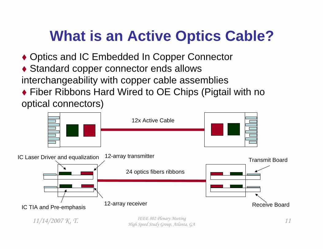
What is an Active Optics Cable?Optics and IC Embedded In Copper ConnectorStandard copper connector ends allows
interchangeability with copper cable assemblies Fiber Ribbons Hard Wired to OE Chips (Pigtail with no
optical connectors)
24 optics fibers ribbons
12-array transmitter
12-array receiver
IC Laser Driver and equalization
IC TIA and Pre-emphasis
Transmit Board
Receive Board
12x Active Cable
11/14/2007 K. T. IEEE 802 Plenary MeetingHigh Speed Study Group, Atlanta, GA 12
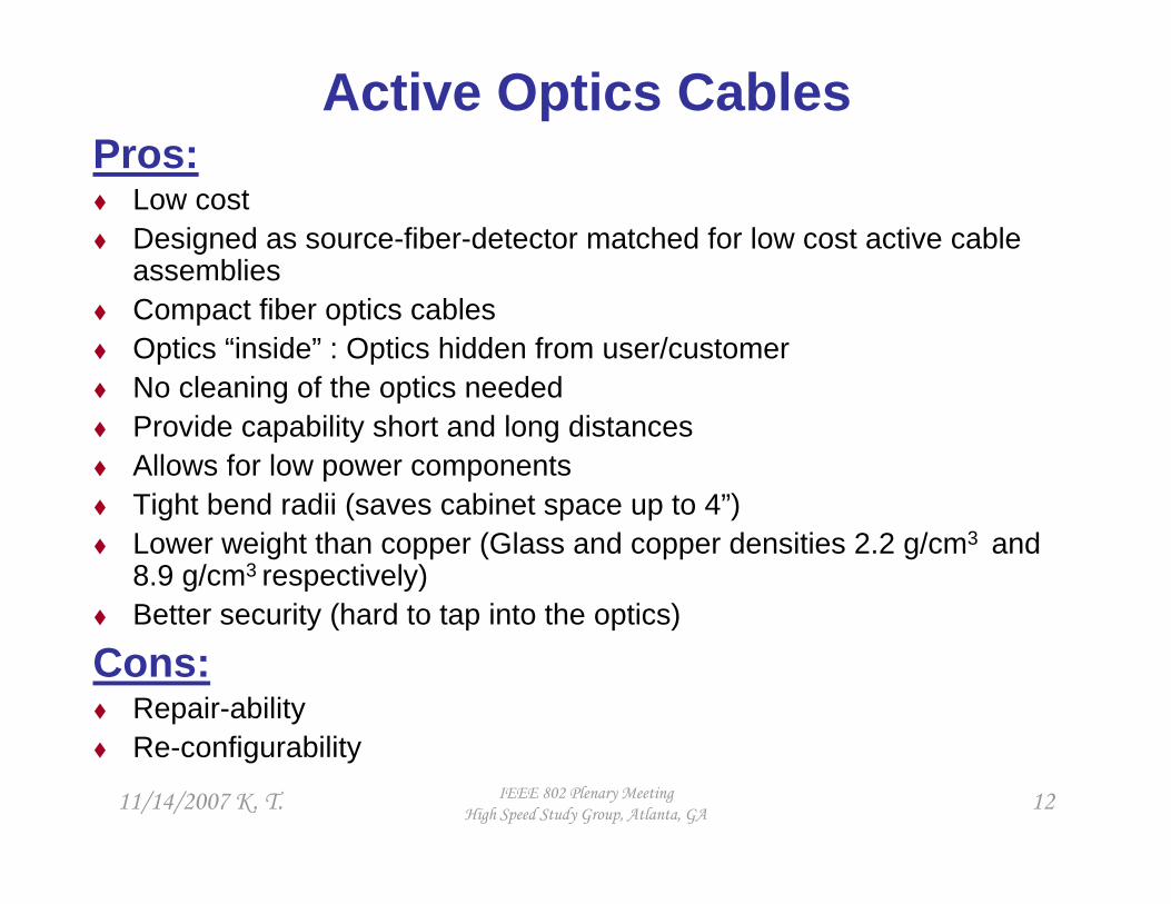
Active Optics CablesPros:
Low costDesigned as source-fiber-detector matched for low cost active cable assemblies Compact fiber optics cablesOptics “inside” : Optics hidden from user/customerNo cleaning of the optics neededProvide capability short and long distances Allows for low power componentsTight bend radii (saves cabinet space up to 4”)Lower weight than copper (Glass and copper densities 2.2 g/cm3 and 8.9 g/cm3 respectively) Better security (hard to tap into the optics)
Cons:Repair-abilityRe-configurability

11/14/2007 K. T. IEEE 802 Plenary MeetingHigh Speed Study Group, Atlanta, GA 13
Transceiver Functional Content• Channel Definition
Equalization Laser Driver VCSEL, DFB, or
EML
Monitor PDAGC
PIN DetectorTIACDR/Post AmpPre-emphasis
Fiber OpticsCable

11/14/2007 K. T. IEEE 802 Plenary MeetingHigh Speed Study Group, Atlanta, GA 14
Examples of Active Optics Cable Suppliers
QSFP and microGIGACN
QSFP
microGIGACN
microGIGACN
QSFP
Connector Package
VCSEL4 x 5 GbpsA
4 x 5 Gbps
4 x 10 Gbps
4 x 5 Gbps
4 x 3.125 Gbps
4-channel active cable
VCSEL
DFB and Silicon Mod.
VCSEL
VCSEL
Laser/Modulator Transmitter
D
E
C
B
Manufacturer
11/14/2007 K. T. IEEE 802 Plenary MeetingHigh Speed Study Group, Atlanta, GA 15
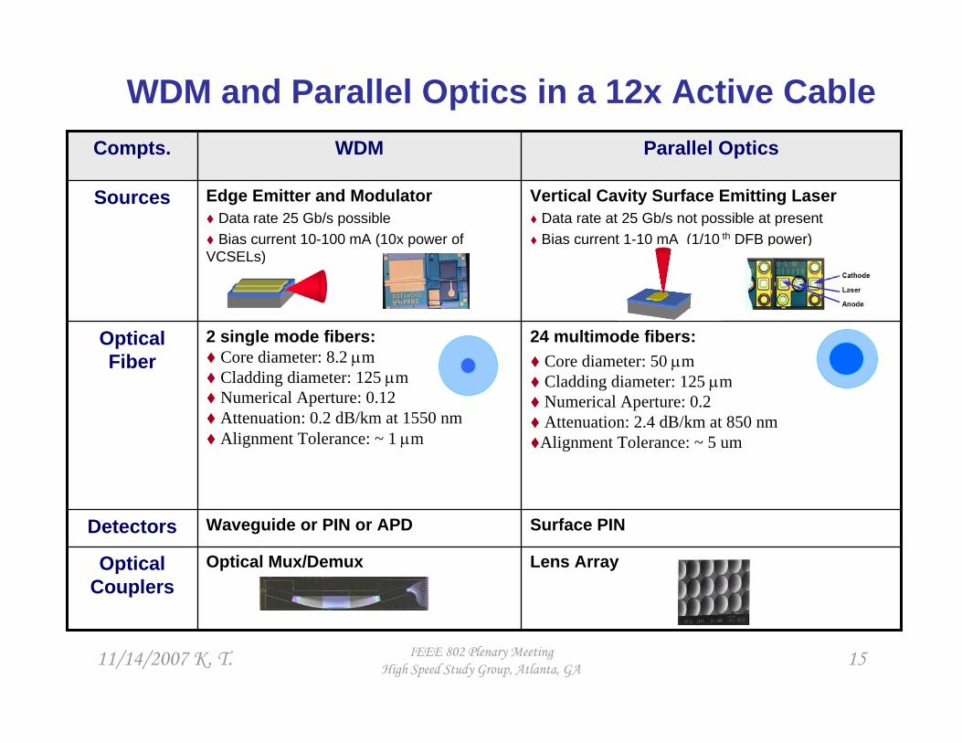
WDM and Parallel Optics in a 12x Active Cable
Surface PINWaveguide or PIN or APDDetectors
Lens ArrayOptical Mux/DemuxOptical Couplers
24 multimode fibers: Core diameter: 50 µmCladding diameter: 125 µmNumerical Aperture: 0.2Attenuation: 2.4 dB/km at 850 nmAlignment Tolerance: ~ 5 um
2 single mode fibers:Core diameter: 8.2 µmCladding diameter: 125 µmNumerical Aperture: 0.12Attenuation: 0.2 dB/km at 1550 nmAlignment Tolerance: ~ 1 µm
Optical Fiber
Vertical Cavity Surface Emitting LaserData rate at 25 Gb/s not possible at present Bias current 1-10 mA (1/10 th DFB power)
Edge Emitter and ModulatorData rate 25 Gb/s possibleBias current 10-100 mA (10x power of
VCSELs)
Sources
Parallel OpticsWDM Compts.

11/14/2007 K. T. IEEE 802 Plenary MeetingHigh Speed Study Group, Atlanta, GA 16
2.3 0.57 x10⁻⁴Wavelength (cm @10 Gbps in cable)
10-5010-50Network Board Trace (cm)5 to 10Up to 100Reach (m) (@10 Gbps)
~ 100~ 200Power per channel (mW)755 to 10Bend Radius (mm)NA~ 0.3Latency per Active End (ps)
☺EMI/EMC
4.284.99Cable Time of Flight Latency (ns/m)10-1210-15BER
☺Cable Volume (cm3)☺Cable Weight (Kg)
~ 2~ 1Cable coupling per end (1 dB)20.002 Loss (dB/m)
Copper ActivesOptics ActivesParameter
Optics Vs Copper Actives
11/14/2007 K. T. IEEE 802 Plenary MeetingHigh Speed Study Group, Atlanta, GA 17
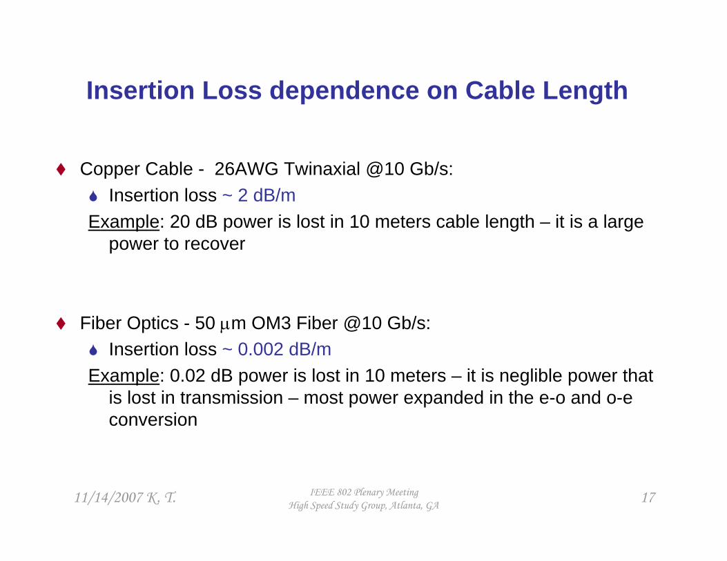
Insertion Loss dependence on Cable Length
Copper Cable - 26AWG Twinaxial @10 Gb/s: Insertion loss ~ 2 dB/m
Example: 20 dB power is lost in 10 meters cable length – it is a large power to recover
Fiber Optics - 50 µm OM3 Fiber @10 Gb/s:Insertion loss ~ 0.002 dB/m
Example: 0.02 dB power is lost in 10 meters – it is neglible power that is lost in transmission – most power expanded in the e-o and o-e conversion

11/14/2007 K. T. IEEE 802 Plenary MeetingHigh Speed Study Group, Atlanta, GA 18
Electrical Connector Options for 12x Active Cables
microGiGa CN 12x Connector
~ 2” Wide with worse board edge densityO-E active components outboard hard to cool
12x Connector proposed at a recent IBTA
~ 1” Wide with better edge board densityThermal: Actives inboard that offers
cooling advantage
Does not meet Cray X-talk budget at 10 Gbps Does not meet Cray board edge density
Active cable industry is encouraged to propose soon a connector and form a 12x active cable MSA.

11/14/2007 K. T. IEEE 802 Plenary MeetingHigh Speed Study Group, Atlanta, GA 19
E-connector Xtalk and Signal Integrity of Complete SerDes –to-SerDes Path
SerDes A Driver
Pkg + Via
StripelineTrace
Connector+ ViaO-to-E Receiver
E-to-O Transmitter
Connector+ Via
StripelineTrace
Pkg + Via
SerDes B Receiver
FEXT1 FEXT2
NEXT1 NEXT2
Signal
Next NeighborForward Aggressor
Next NeighborBackward AggressorKeep FEXT and NEXT better than -35 dB

11/14/2007 K. T. IEEE 802 Plenary MeetingHigh Speed Study Group, Atlanta, GA 20
Conclusion
Advocate 12x active optics cable for the “at least” 100 meters on OM3 physical layer objective:
Need to consider 12x duplex active optics @10+ Gbps per channel and form an MSA early to meet HPC timeline.
Need to define a 12x active cable electrical connector early.
Thank You