Embed Size (px)
Citation preview

221966B.12.04
All replacement parts
All labour charges
All call-out charges
Guarantee Registration
100FF 120FF
Fanned Flue Boiler
This is a Cat I2H
Appliance
BS 6332BS 5258
Reference in these instructions to British Standards and StatutoryRegulations/Requirements apply only to the United Kingdom.
For Ireland the rules in force must be used.
To b e l e f t w i t h t h e u s e r
4272
❏✔
❏✔
❏✔
Instructions for UseInstallation and Servicing
G.C. No. 41 047 59 G.C. No. 41 319 75
REGISTER YOUR GLOW-WORM APPLIANCEFOR 1ST YEAR GUARANTEE PROTECTION
CALL 0800 073 2142Glow-worm,
Nottingham Road, Belper, Derbyshire. DE56 1JTGeneral/Sales enquiries:
Tel: (01773) 824141 Fax: (01773) 820569www.glow-worm.co.uk
Tel: (01773) 828100
Fax: (01773) 828070
Thank you for installing a new Glow-worm appliance in your home.
Glow-worm appliances' are manufactured to the very highest standard so we are pleasedto offer our customers' a Comprehensive First Year Guarantee.
We recommend you complete and return your Guarantee Registration Card as soon as possible.
If this card is missing you can obtain a copy or record your registration by telephoning the Glow-worm CustomerService number 01773 828100.
Our Guarantee gives you peace of mind plus valuable protection against breakdown by covering the cost of:
The instructions consist of three parts, User, Installation and Servicing Instructions.The instructions are an integral part of the appliance and must, to comply with the current issue of theGas Safety (Installation and Use) Regulations, be handed to the user on completion of the installation.

2221966B
Important Information
Testing and CertificationThis boiler is tested and certificated for safety and performance. It is therefore important that no alteration is made to the boiler, withoutpermission, in writing, from Glow-worm.
Any alteration not approved by Glow-worm, could invalidate the certification, boiler warranty and may also infringe the current issueof the Statutory Requirements, see Section 1.4.
CE MarkThis boiler meets the requirements of Statutory Instrument No. 3083 The boiler (Efficiency) Regulations, and therefore is deemedto meet the requirements of Directive 92/42/EEC on the efficiency requirements for new hot water boilers fired with liquid or gaseousfuels.
Type test for purposes of Regulation 5 certified by: Notified body 0086.
Product/productioncertifiedby: Notified body 0086.
The CE mark on this appliance shows compliance with:
1. Directive 90/396/EEC on the approximation of the laws of the Member States relating to appliances burning gaseous fuels.
2. Directive 73/23/EEC on the harmonization of the Laws of the Member States relating to the electrical equipment designed for use within certain voltage limits.
3. Directive 89/336/EEC on the approximation of the Laws of the Member States relating to electromagnetic compatibility.
INFORMATION FOR THE INSTALLER AND SERVICE ENGINEER.Under Section 6 of The Health and Safety at Work Act 1974, we are required to provide information on substances hazardous tohealth.
REFRACTORY CERAMIC FIBREThis product uses insulation material containing Refractory Ceramic Fibre (RCF), which are man-made vitreous silicate fibres.Excessive exposure to these materials may cause temporary irritation to eyes, skin and respiratory tract, consequently, it makessense to take care when handling these articles to ensure that the release of dust is kept to a minimum.
To ensure that the release of fibres from these RCF articles is kept to a minimum, during installation and servicing we recommendthat you use a HEPA filtered vacuum to remove any dust accumulated in and around the boiler before and after working on the boiler.When replacing these articles we recommend that the replaced items are not broken up, but are sealed within heavy duty polythenebags, clearly labelled as RCF waste. This is not classified as “hazardous waste” and may be disposed of at a tipping site licensedfor the disposal of industrial waste. Protective clothing is not required when handling these articles, but we recommend you followthe normal hygiene rules of not smoking, eating or drinking in the work area and always wash your hands before eating or drinking.
INSULATION PADS, GLASSYARN.These can cause irritation to skin, eyes and the respiratory tract. If you have a history of skin complaint you may be susceptible toirritation. High dust levels are usual only if the material is broken. Normal handling should not cause discomfort, but follow normalgood hygiene and wash your hands before eating, drinking or going to the lavatory. If you do suffer irritation of the eyes or severeirritation to the skin seek medical attention.
THERMOSTATSThese contain very small amounts of xylene in the sealed phial and capillary. If broken, under normal circumstances the fluid doesnot cause a problem, but in case of skin contact, wash with cold water. If swallowed drink plenty of water and seek medical attention
CUT-OFF DEVICESThese contain activated charcoal and a very small amount of chlorodifluormethane in the sealed phial and capillary. If broken, undernormal circumstances the fluid does not cause a problem. If there is irritation to the eyes or skin then seek medical attention.
Spare PartsREMEMBER: When replacing a part on this appliance, use only spare parts that you can be assured conform to the safety andperformance specification that we require. Do not use reconditioned or copy parts that have not been clearly authorised by Glow-worm.

3 221966B
Introduction 3Lighting the Boiler 5
General Data 1 6Flue Terminal 2 9Water Systems 3 10Flue and Appliance Preparation 4 13Boiler Installation 5 17Flue Fixing 6 19Electrical Connectors 7 20Commissioning 8 21Instructions to the User 9 24
Servicing 10 24Fault Finding 11 27Replacement of Parts 12 31Spare Parts 13 34
CONTENTS DESCRIPTION SECTION PAGE No.
INSTRUCTIONS
FOR USE
INSTALLATION
INSTRUCTIONS
SERVICING
INSTRUCTIONS
IntroductionWARNING: It is important that the case (not the controls tray)is not disturbed or removed other than for servicing by acompetent person.
The user shall not interfere with or adjust sealed parts.
Please read these instructions and follow them carefully for thesafe and economical use of your boiler.
The Ultimate FF series are fanned flue boilers designed toprovide central heating and indirect domestic hot water.
The boiler is fully automatic in operation having only one usercontrol, the control thermostat.
IMPORTANT NOTICEThis boiler is for use only on natural gas (G20).
The Gas Safety (Installation and Use)RegulationsIn your interest and that of gas safety it is the law that ALL gasappliances are installed by a competent person in accordancewith the above regulations.
Gas Leak or FaultTurn off the gas emergency control valve immediately. Eliminateall sources of ignition, i.e.smoking, blowlamps, hot air guns etc.Do not operate electrical lights or switches either on or off. Openall doors and windows,ventilate the area.
Electrical Supply FailureFailure of the electrical supply will cause the burner to go out.Should this occur, operation of the appliance will normallyresume after the electrical supply is restored.
If the boiler does not relight after an electrical supply failure theoverheat safety cutoff device may need resetting, remove thecontrols cover and press the reset button, refer to diagram 1.
Overheat Safety CutoffIf the overheat safety cutoff device operates on any otheroccasion than an electrical supply failure, press the reset buttonas in “Electrical Supply Failure”. If the overheat operates again,turn the appliance off and contact your installation/servicingcompany.
Instructions for Use
Important Information

4221966B
MaintenanceTo ensure the continued efficient and safe operation of theboiler it is recommended that it is checked and serviced asnecessary at regular intervals. The frequency of servicing willdepend upon the particular installation conditions and usage,but in general once a year should be enough.
If this appliance is installed in a rented property in the UK thereis a duty or care imposed on the owner of the property by thecurrent issue of The Gas Safety (Installation and Use)Regulations, Section 35.
It is the law that any servicing is carried out by a competentperson.
To obtain service, please call your installer or Glow-worm’s ownService Organisation using the telephone number given on thecontrols tray.
Please be advised that the ‘Benchmark’ logbook should becompleted by the installation engineer on completion ofcommissioning and servicing.
All CORGI Registered Installers carry a CORGI ID card, andhave a registration number. Both should be recorded in yourboiler Logbook. You can check your installer is CORGI registeredby calling CORGI direct on :- 01256 372300.
Boiler ClearancesIf fixtures are positioned close to the boiler space must be leftas shown in diagram 2. At least a minimum clearance of 500mmmust be left in front of the boiler to allow for servicing.
Boilers Installed in a Compartment orCupboardIf the boiler is installed in a compartment or cupboard do notobstruct any ventilation openings.
Do not use the compartment or cupboard for storage.
CleaningWARNING: This appliance contains metal parts (components)and care should be taken when handling and cleaning, withparticular regard to edges.
Clean the casing occasionally by wiping it over with a dampcloth or dry polishing duster.
Do not use an abrasive cleaner.
Boiler Electrical SupplyWARNING: This boiler must be earthed.
The boiler must only be connected to a 230V~50Hz supplyprotected by a 3A fuse.
All system components shall be of an approved type and shallbe connected in accordance with the current issue of BS7671and any applicable local regulations.
External wiring must be correctly earthed, polarised and inaccordance with the relevant standards.
In GB this is BS 6891.
In IE this is the current edition of I.S.813 "Domestic GasInstallations".
Wiring to the boiler must be PVC insulated type to the currentissue of BS6500 Table 16, not less than 0.75mm2 (24/0.20mm).
Instructions for Use
4140
Diagram 1
4625
CONTROLS COVER
DATA &SERIALNUMBERLABEL
RESETBUTTON
30FF to 60FF Ultimate User Controls illustrated, detailsfor the 70FF to 120FF are different but the controls arethe same.
VIEWING WINDOW
SETTING POINT
CONTROLTHERMOSTATKNOB GAS SERVICE
COCK (ShownOff)
The colours of three core flexible cable are:
Brown - live, Blue - neutral,
Green/yellow - earth.
As the markings on your plug may not correspond with thesecolours continue as follows:
The cable coloured blue must be connected to the terminalmarked “N” or black.
The cable coloured brown must be connected to the terminalmarked “L” or red.
The cable coloured green/yellow must be connected to theterminal marked “E”, or green or the earth symbol .
5 221966B
0208
M
6mm
6mm
65mm
6mm6mm
6mm
160mm
500mm
Additional clearances may berequired for installation
FRONTVIEW
Diagram 2
To Light the BoilerWARNING: Sealed Systems
Do not operate the boiler wthout water.
A sealed water system must be filled and pressurised by acompetent person.
Only light the boiler when you are sure that the system has beenfilled and pressurised.
The pressure gauge should show at least 0.7bar, anything lessthan this figure could indicate a leak and you MUST contact yourinstallation/servicing company.
If there is any doubt about the boiler being full of water consultyour installation/servicing company.
ALL SYSTEMS:
Turn the electrical supply on to the boiler and check that allremote controls are calling for heat.
To Turn the Boiler OnRemove the controls cover, by withdrawing it forward and off,see diagram 1.
Turn the control thermostat knob clockwise to any positionbetween MIN and MAX. The maximum temperature setting isabout 82oC (180oF), see diagram 1.
The boiler lighting operation is now automatic as follows.
The fan operates, followed by an ignition spark until the pilot islit. When the pilot is alight the ignition system switches off andthe main burner lights. The flames can be seen through theviewing window, see diagram 1.
The main burner will remain alight until switched off by thecontrol thermostat or any remote control.
If the boiler is switched OFF, by hand, wait at least 30 secondsbefore switching on again.
When the boiler switches off, both the pilot and main burner goout.
The automatic lighting sequence will operate again when heatis required.
Refit the controls cover.
It should be noted that this is a fan flue appliance and fanoperation may be heard.
To Turn the Boiler OffFor short periods, turn the control thermostat knob anti-clockwiseto “O” Off. To relight, turn the control thermostat knob to anyposition between “MIN” and “MAX”.
For longer periods, turn the control thermostat knob fully anti-clockwise to “O” Off and switch off the electrical supply to theboiler.
To relight follow the lighting sequence given above.
Protection Against Freezing.If the boiler is to be out of use for any long period of time duringsevere weather conditions we recommend that the whole of thesystem, including the boiler, be drained off to avoid the risk offreezing up. Make sure that, if fitted, the immersion heater in thecylinder is switched off.
For the position of the serial number, see diagram 1.
Instructions for Use

6221966B
Diagram 1.1
SIDE ELEVATION FRONT ELEVATION
B
A O
C
P
L
CL
M
F
GH
PU
MP
ED
FLO
W
PU
MP
ED
RE
TU
RN
K
0301
M
���
�����
JWATER CONNECTIONS28mm COPPER PIPE
GAS CONNECTIONSRC1/2 (1/2 in. BSPT)
MODEL A B C D E F G H J K L M O
100FF,120FF 67 300 58 127 114 450 168 132.5 835 772 63 132 43
P
78.5
D
E
IMPORTANT NOTICEThis boiler is for use on Natural Gas (G20) as distributed in theUnited Kingdom and Ireland and cannot be used on any othergas. This boiler must be installed by a competent personONLY.
This boiler can be used on open vented or sealed watersystems.
When used on an open vented system domestic hot water canonly be provided by pumped circulation to the indirect cylinder.
Wherever possible, all materials, appliances and componentsused shall comply with the requirements of applicable BritishStandards.
Where no British Standard exists, materials and equipmentshould be fit for their purpose and of suitable quality andworkmanship.
Refer to Manual Handling Operations, 1992 regulations.
Sheet Metal PartsWARNING: When installing or servicing this boiler care shouldbe taken when handling sheet metal parts, to avoid any possibilityof personal injury.
1.1 Statutory RequirementsIn GB the installation of the boiler must be carried out by acompetent person as described in the following regulations:
The manufacturer’s instructions supplied.
The Gas Safety (Installation and Use) Regulations.
The appropriate Buildings Regulations either The BuildingRegulations, The Building Regulations (Scotland),The BuildingRegulations (Northern Ireland).
The Water Fittings Regulations or Water byelaws in Scotland.
The Health and Safety at Work Act, Control of SubstancesHazardous to Health (COSHH).
The Current I.E.E. Wiring Regulations.
Where no specific instructions are given, reference should bemade to the relevant British Standard Code of Practice.
In IE, the installation must be carried out by a competentperson and installed in accordance with the current edition ofI.S.813 "Domestic Gas Installations", the current BuildingRegulations and reference should be made to the current ETCIrules for Electrical Installation.
In GB the following Codes of Practice apply:
BS4814, BS6798, BS5440 Part 1 and 2, BS5546 Part 1,BS5449, BS6891, BS6700, BS7074 Part 1 and 2, BS7593,BS7671.
In IE: I.S.813, BS5546, BS 5449, BS 7074, BS 7593.
Manufacturer’s instructions must not be taken as overridingstatutory requirements.
1.2 DataSee Table 1
All dimensions are given in millimetres (except as noted).
*NOTE: Lift weight is with Flue Elbow, Controls Cover and FrontCover removed.
The Seasonal Efficiency Domestic Boilers UK (SEDBUK) isUltimate 100FF = 79, Ultimate 120FF = 78.1.
The value is used in the UK Government’s Standard AssessmentProcedure (SAP) for energy rating of dwellings. The test datafrom which it has been calculated have been certified by B.S.I.
1.3 Range RatingThis boiler is range rated and may be adjusted to suit individualsystem requirements.
Table 2 gives the ratings and settings.
1 General

7 221966B
1.4 B.S.I. CertificationThis boiler is certificated to the current issue of BS6332 Part 1,invoking the current issue of BS5258 Part 1 for performanceand safety. It is, therefore, important that no alteration is madeto this boiler without permission, in writing, from Glow-worm.
Any alteration that is not approved by Glow-worm, couldinvalidate the B.S.I. Certification of the boiler, warranty andcould also infringe the current issue of the StatutoryRequirements.
1.5 Gas SupplyThe gas installation shall be in accordance with the relevantstandards.
In GB this is BS6891.
In IE this is the current edition of I.S.813 "Domestic GasInstallations".
The supply from the governed meter must be of adequate sizeto provide a steady inlet working pressure of 20mbar (8in wg) atthe boiler.
On completion test the gas installation using the pressure dropmethod and suitable leak detection fluid, purge in accordancewith the current issue of BS6891.
1.6 Electrical SupplyWARNING: This boiler must be earthed.
All system components shall be of an approved type and shallcomply with and be connected in accordance with the currentissue of BS7671 and any applicable local regulations.
External wiring must be correctly earthed, polarised and inaccordance with the relevant standards.
In GB this is BS 6891.
In IE this is the current edition of I.S.813 "Domestic GasInstallations".
Connection of the boiler and system controls to the mainssupply must be through a common isolator and must be fused3A, maximum. This method of connection must be by a fuseddouble pole isolating switch with a minimum contact separation
26.4490,210
32.38110,485
23.4580,000
29.31100,000
33.43114,066
39.6135,150
29.3100,000
35.17120,000
3.5125
4.2148
29.24 99,760
26.3890,000
9.23.7
14.45.8
11.64.7
2.8100
3.5123
3.1111
205727
4.7mm
TABLE 2. 100FF
RANGE RATING
NOMINALHEATINPUT(NETT)
Min. Max.Med.
NOMINALHEATOUTPUT
APPROX.GASRATE
BURNER INJECTOR MARKING:
kW
Btu/h
kW
Btu/h
m3/h
ft3/h
BURNER INJECTOR SIZE:
TABLE 2. 120FF
RANGE RATING
NOMINALHEATINPUT(NETT)
Min. Max.
36.52124,608
32.24110,000
3.9137
Medium.
NOMINALHEATOUTPUT
APPROX.GASRATE
BURNER INJECTOR MARKING: 205726
kW
Btu/h
kW
Btu/h
m3/h
ft3/h
9.94.0
14.25.7
12.04.8
BURNER.SETTINGPRESSURE
BURNER.SETTINGPRESSURE
m bar
in. wg.
m bar
in. wg.
BURNER INJECTOR SIZE: 5.2mm
of 3mm on both poles. The switch should be readily accessibleand preferably adjacent to the appliance. It should supply theappliance only and be easilyidentifiable as so doing.
Alternatively, an unswitched shuttered socket outlet and 3Afused 3 pin plug both to the current issue of BS1363 may beused, provided that they are not used in a room containing abath or shower.
Wiring to the boiler must be PVC insulated type to the currentissue of BS6500 Table 16.
1.7 Contents of PackagingThe boiler is delivered in one pack, refer to Section 4.1 forcontents.
Refer to Section 4.2 to check that the flue terminal assemblysupplied is suitable.
1.8 Water SystemThis boiler may be fitted to an open vented or sealed watersystem.
1 General
DATA TABLE 1.
MODEL
TOTAL DRYWEIGHT(IncludingTerminal)
LIFT WEIGHT
WATERCONTENT
GASCONNECTION
ELECTRICITYRATING
WATERCONNECTION
ELECTRICITYSUPPLY
DATA LABEL
100FF
Rc 1/2 in.
71W 97W
Internal fuse F1 & F2 (F1A)
2x28mm copper pipes fromtop of case
230V~50Hz, fused 3A
Bottom right hand side of case
71.0 kg(157 lb)
120FF
71.0 kg(157 lb)
63.3 kg(140 lb)
63.3 kg(140 lb)
3.8 litres(0.84 gal)
3.8 litres(0.84 gal)
9072
*
9715

8221966B
It is recommended that plastic pipes for primary pipeworkshould not be used for this boiler.
1.9 DrainSystem
A draining tap must be provided at the lowest points of thesystem which will allow the entire system, boiler and hot watercylinder to be drained.
Draining taps should be to the current issue of BS2879.
Boiler
A draining point is fitted at the bottom right hand side of the heatexchanger.
Cover controls to avoid water damage.
If required remove the combustion chamber front cover toimprove access.
1.10 Safety ValveA safety valve need not be fitted to an open vented system.
1.11 LocationThis boiler is not suitable for outdoor installation.
This boiler is suitable for installation in bathroom zones 2 and 3.
The boiler may be installed in any room, although particularattention is drawn to the requirements of BS7671 with respectto the installation of a boiler in a room containing a bath orshower. Any electrical switch should be so positioned that itcannot be touched by a person using the bath or shower. Theelectrical provisions of the Building Standards (Scotland)Regulations apply to such installations in Scotland.
In GB this is the current I.E.E. WIRING REGULATIONS andBUILDING REGULATIONS.
In IE reference should be made to the current edition of I.S.813"Domestic Gas Installations" and the current ETCI rules.
The boiler must be mounted on a flat wall which is sufficientlyrobust to take its total weight.
The boiler may be fitted to a wall made of combustible material.
1.12 Boiler ClearancesRefer to diagram 1.2.
The boiler must be positioned so that at least the minimumoperational and servicing clearances are provided.
Additional clearances may be required for installation.
If fixtures are positioned next to the boiler they should be maderemovable for access to pipework.
Sufficient clearance must be left in front of the boiler forservicing.
1.13 Room VentilationThe boiler is room sealed and does not require the room orspace containing it to have permanent airvents.
1.14 Boilers in a CompartmentWhere the installation of the boiler will be in an unusual position,special requirements are needed, the current issue of BS6798gives detailed guidance on these requirements.
A compartment used to enclose the boiler must be designedand constructed specifically for this purpose. An existingcupboard or compartment modified for the purpose may beused. Details of essential requirements for cupboard orcompartment design are given in the current issue of BS6798.
The doorway opening should be of sufficient size to allow foreasy removal of the boiler.
Where the boiler is fitted in a cupboard or compartment,permanent high and low level ventilation must be provided. Theminimum ventilation areas are given in Table 3.
1.15 Timber Frame BuildingIf the boiler is to be installed in a timber frame building it shouldbe fitted in accordance with the Institute of Gas Engineersdocument IGE/UP/7/1998. If in doubt seek advice from the localgas undertaking or Glow-worm.
1.16 Heating System ControlsThe heating system should have installed: a programmer androom thermostat controlling the boiler.
Thermostatic radiator valves may be installed, however theymust not be fitted in a room where the room thermostat islocated.
NOTE: For further information, see the current issue of theBuilding Regulations, approved document L1, and thereferences:
1) GIL 59, 2000: Central heating system specification (CheSS)and
2) GPG 302, 2001: Controls for domestic central heatingsystem and hot water. BRECSU.
0208
M
6mm
6mm
65mm
6mm6mm
6mm
160mm
500mm
Additional clearances may berequired for installation
FRONTVIEW
MINIMUM CLEARANCES FROM WALLS CEILING,FLOOR, CUPBOARD, WORKTOPS, ANDINFLAMMABLE MATERIALS
PLANVIEW
TABLE 3. COMPARTMENT AIR VENTS
VENTILATIONREQUIREMENTS
VENTILATIONFROMROOMOR SPACE
MODEL
VENTILATIONFROMOUTSIDE
100FF
HIGH LEVELVENT AREA
LOW LEVELVENT AREA
100FF 330 51 330 51
396 61.5 396 61.5
cm2 in2 cm2 in2
120FF
120FF
165 25.5 165 25.5
198 30.5 198 30.5
0209
M
Diagram 1.2
1 General

9 221966B
NOTE: Detailed recommendations for flues are given in thecurrent issue of BS5440 Part 1.
2.1 Terminal PositionThe minimum acceptable siting dimensions for the terminalfrom obstruction, other terminals and ventilation openings areshown in diagram 2.1. For Ireland the minimum distances forflue terminal positioning must be those detailed in I.S.813"Domestic Gas Installations".
The terminal must be exposed to the external air, the positionallowing free passage of air across it at all times.
Car ports or similar extensions of a roof only, or a roof and onewall, require special consideration with respect to any openings,doors, vents or windows under the roof. Care is required toprotect the roof if it is made of plastic sheeting. If the car portconsists of a roof and two or more walls, seek advice from thelocal gas company before installing the boiler.
If the terminal is fitted within 600mm below plastic guttering orpainted soffit an aluminium shield 1500mm long should be fittedimmediately beneath the guttering or eaves. If the terminal isfitted within 450mm below painted eaves or a painted gutter, analuminium shield 750mm long should be fitted immediatelybeneath the guttering or eaves.
2.2 Terminal GuardA terminal guard is required if persons could come into contactwith the terminal or the terminal could be subject to damage.
If a terminal guard is required, it must be positioned to providea minimum of 50mm clearance from any part of the terminal andbe central over the terminal.
A suitable guard, reference Type K3, can be obtained from:
Tower Flue Components LtdMorley RoadTonbridgeKentTN9 1RA
Under Car Port etc.
H,I
JD
FK
Diagram 2.1
0103
M43
07
A
A
FG E
A
G
G
G
B,C B,C
F FK
K
K
C
G
L L
2 Flue Terminal
MINIMUM SITING DIMENSIONS FORFANNED FLUE TERMINALS POSITION
A DIRECTLY BELOW, ABOVE OR HORIZONTALLY
TO AN OPENING, AIR BRICK, OPENING WINDOWS,
AIR VENT OR ANY OTHER
VENTILATION OPENING. 300
B BELOW GUTTER, DRAIN/SOIL PIPE 75
C BELOW EAVES 200
D BELOW A BALCONY OR CAR PORT 200
E FROM VERTICAL DRAIN PIPES AND SOIL PIPES 25
F FROM EXTERNAL CORNERS 25
G ABOVE ADJACENT GROUND OR BALCONY LEVEL 25
H FROM A SURFACE FACING THE TERMINAL 600
I FACING TERMINALS 1200
J FROM OPENING (DOOR/WINDOW) INCAR PORT INTO DWELLING 1200
K VERTICAL FROM A TERMINAL 1500
L HORIZONTALLY FROM A TERMINAL 300
M FROM INTERNAL CORNERS 25
MINIMUMSPACING in mm
M

10221966B
The installation of the boiler must comply with the requirementsof the current issue of BS6798, in Ireland, refer also to thecurrent edition of I.S.813 "Domestic Gas Installations".
In GB it is necessary to comply with the Water Supply (WaterFittings) Regulations 1999 (for Scotland, the Water Byelaws2000, Scotland).
To comply with the Water regulations your attention is drawn to:The Water Regulations guide published by the Water RegulationsAdvisory Service (WRAS) gives full details of the requirements.
In IE the requirements given in the current edition of I.S.813"Domestic Gas Installations" and the current Building Regulationsmust be followed.
It is recommended that plastic pipes for primary pipeworkshould not be used for this boiler.
3.1 Frost ProtectionIf the position of the boiler is such that it may be vulnerable tofreezing it should be protected as specified in the current issueof BS5422. It is recommended that a frost protection thermostatbe fitted.
3.2 PumpThe pump, with integral valves, should be fitted in the heatingflow pipework from the boiler, it should be set to produce atemperature difference of 11oC (20o), between the flow andreturn, with the control thermostat set at “MAX”, which is about82oC (180oF).
The pressure loss of the boiler can be found from diagram 3.1.
High resistance microbore systems may require a higher dutypump.
3.3 Bypass - Fully Pumped and Sealed WaterSystemA bypass MUST be fitted to a fully pumped and sealed watersystem.
Where the water system allows the boiler and pump to operateon bypass only, the bypass connection must be at least 2.5metresaway from the boiler.
The flow through the boiler must not be allowed to fall such thatthere is a temperature difference greater than 20oC between theflow and return.
3.4 Water SystemFor an open vented system the boiler must be supplied from anunrestricted water supply taken from a feed and expansioncistern fitted at a maximum height of 27metres above the boiler.
The cold feed must be 15mm minimum size.
It is important that the relative positions of the pump, cold feedand open vent are as shown in diagram 3.2.
The unrestricted open vent from the boiler must rise continuouslyto over the feed and expansion cistern.
3.5 Domestic Hot Water SystemGeneral - All domestic hot water circuits, connections, fittingsmust be in accordance with the relevant standards and watersupply regulations.
For GB: Guidance G17 to G24 and recommendation R17 toR24 of the Water Regulations Guide.
For IE: The current edition of I.S.813 "Domestic Gas Installations".
The domestic hot water service must be in accordance with thecurrent issue of BS5546, refer also to the current issue ofBS6700.
3.6 Indirect CylinderFor all systems supplying domestic hot water the cylinder mustbe indirect. It is recommended that the indirect cylinder be fittedwith some form of temperature control.
3.7 Fully Pumped Heating and Domestic HotWaterThe connections for this type of system MUST be as shown indiagram 3.2 and 3.3.
3.8 InhibitorAttention is drawn to the current issue of BS5449 and BS7593on the use of inhibitors in central heating systems.
If an inhibitor is to be used, contact a manufacturer or Glow-worm, for their recommendations as to the best product to use.
When installing in an existing system take special care to drainthe entire system, including the radiators, then thoroughlycleaning out before installing the boiler whether or not adding aninhibitor.
3.9 Sealed Water SystemsThe installation should comply with the appropriate requirementsof the current issue of BS4814, BS5449, BS6759, BS6798 andBS7074 Part 1 and 2, see diagram 3.4 for a suggested layout.
3.10 Safety ValveA safety valve must be fitted to a sealed water system.
It shall be preset, nonadjustable with a lift pressure of 3bar,incorporating seating of resilient material, a test device and aconnection for drain.
The drain from the safety valve must be routed clear of anyelectrical fittings and positioned so that any discharge can beseen.
Diagram 3.1
Flow rate (litres/minute)
Wat
er p
ress
ure
loss
(m
m h
ead
of w
ater
)
PRESSURE LOSSOF BOILER 100FF/120FF
Design Flow Rate
0088
(z)M
750
500
250
0
0 5 10 15 20 25 30 35 40 45
700mm (120FF)
450mm (100FF)
3 Water Systems

11 221966B
3.11 Expansion VesselA diaphragm type expansion vessel, conforming to the currentissue of BS4814 (see also BS7074 Part 1 and 2) must beconnected at a point close to the inlet side of the circulatingpump, see diagram 3.4, unless laid down differently by themanufacturer.
The expansion vessel volume depends upon the total watersystem volume and the initial system design pressure. For anysystem an accurate calculation of vessel size is given in thecurrent issue of BS5449 and BS7074 Part 1, for IE refer to thecurrent edition of I.S.813 "Domestic Gas Installations".
Example. For an initial system design pressure of 0.7bar theminimum total vessel volume required is 0.063xTotal Systemvolume.
NOTE: A higher initial design pressure requires a larger volumeexpansion vessel.
The charge pressure must not be less than the static head of thesystem, that is, the height of the highest point of the systemabove the expansion vessel.
The water content of the boiler is given in Data Table 1.
3.12 Pressure GaugeA pressure gauge with a set pointer and covering at least therange of 0 to 4bar (0 to 60lb/in2) shall be permanently fitted tothe system in a position where it can be seen when filling thesystem.
Diagram 3.2
6349
FEED ANDEXPANSIONCISTERN
22mm VENT(MIN.)
15mm (MINIMUM)COLD FEED
OPEN VENTED FULLY PUMPED WATER SYSTEMRECOMMENDED RELATIONSHIP BETWEENPUMP COLD FEED AND VENT
450mmMIN.HEIGHT
1150mmMIN. R
ET
UR
N
FLO
W
CY
LIN
DE
R
PUMP
HE
AT
ING
150mmMAX.
There must always be a cold waterpath to the returnconnectionof the boiler.
BOILER 28mm (MINIMUM)BY-PASS WITHLOCKSHIELD VALVE
FLOW
RET.
Diagram 3.3
28mmPIPE
FLOW RETURN
4273
1metre Min.27 metres
Max.
22mm FOR COMBINED FEED & VENTTO BE FITTED IN ACCORDANCE WITH BS 5449
INDIRECTCYLINDER
ALTERNATIVESYSTEMCONTROLVALVES
HEATINGSYSTEM
PUMP
FULLY PUMPED CIRCULATIONBYPASS (DIAGRAMMATIC)
BYPASS 28mmMIN WITH LOCKSHIELDVALVE
1metre Min.27 metres
Max.
INDIRECTCYLINDER
ALTERNATIVESYSTEMCONTROLVALVES
HEATINGSYSTEM
PUMP
FULLY PUMPED CIRCULATIONBYPASS (DIAGRAMMATIC)
BYPASS 28mmMIN WITH LOCKSHIELDVALVE
22mm VENT & 15mm COLD FEEDTO BE FITTED IN ACCORDANCEWITH BS 5449
6459
6466
3 Water Systems
12221966B
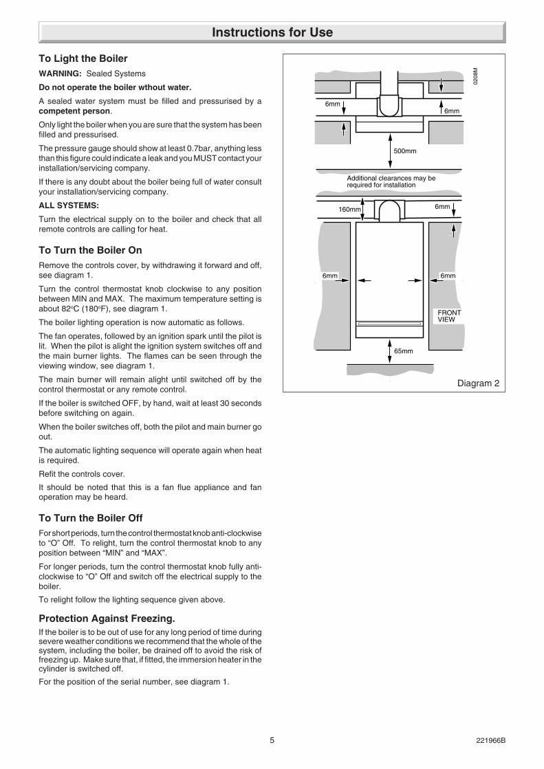
3.13 Domestic Hot Water CylinderSINGLE FEED INDIRECT CYLINDERS ARE NOT SUITABLE.
The domestic hot water cylinder must be if the indirect coil type.It must be suitable for working at a gauge pressure of 0.35barabove the safety valve setting.
3.14 Domestic Hot Water System - UnventedWhere a storage system will not have a vent to atmosphere theinstallation must comply with Building Regulations and theLocal Water Company Byelaws, see also the current issue ofBS6700.
If fitting into an existing system, the local authority must also beadvised.
3.15 Filling a Sealed Water SystemProvision for filling the system at low level must be made. Threemethods are shown in diagram 3.5. There must be no permanentconnection to the mains water supply, even through a non-return valve.
3.16 Water MakeupProvision must be made for replacing water lost from thesystem. A make up vessel mounted above the highest point ofthe system and connected through a non-return valve to thesystem on the return side of either the hot water cylinder orheating system, see diagram 3.4.
Alternatively provision for make up can be made by a filling loop.
3 LITRES (0.66 gals)MAKE-UP BOTTLE(if required)
NON-RETURNVALVE
AUTOAIRVENT
FLOW
DRAINCOCK
BOILER
SAFETYVALVE
(Make-upalternatives) EXPANSION
VESSEL
PRESSUREGAUGE
CIRCULATINGPUMP
FILLING POINT
AIRRELEASEPOINT
HE
AT
ING
CIR
CU
IT 22mm (min)BY-PASS WITHLOCKSHIELD VALVE
RETURN
Diagram 3.4
6252
(Make-upalternatives)
METHOD 1
METHOD 2
METHOD 3
SUPPLY STOPVALVESUPPLY
PIPE
HOSEUNIONS
SERVICINGVALVE
TEMPORARYHOSE
HEATINGSYSTEM
HEATINGSYSTEMTEMPORARY
HOSE
HOSEUNIONS
SERVICINGVALVE
SUPPLYPIPE
SUPPLY STOPVALVE
DOUBLE CHECKVALVE ASSEMBLY
HEATINGSYSTEMSERVICING
VALVE
SUPPLYSTOP VALVE
SUPPLYPIPE
HOSEUNIONS DOUBLE CHECK
VALVE ASSEMBLY
OVERFLOWCISTERN
COMBINEDCHECK VALVEAND VACUUMBREAKER
PRESSUREREDUCINGVALVE
0051M
Diagram 3.5
3 Water Systems

13 221966B
4.1 UnpackingOpen the carton, check the items supplied against the boilerpack contents list on the flap, see diagram 4.1.
4.2 Flue Position and LengthDetermine flue applications, length and terminal position beforestarting.
Refer to diagram 4.2 or 4.3.
NOTE: If a longer flue duct is required DO NOT extend theducting.
A 1, 2 or 3metre flue system and terminal MUST be used, for the100FF and 1 or 2 metre only for the 120FF.
NOTE: If required, an optional Wall Liner Kit, part No.452481,is available, complete with fixing instructions.
4.3 Flue PreparationAll flue assemblies are designed for internal installation (optionalwall liner is required), given that there is sufficient clearancesopposite to the flue for the installation of the flue.
If there is insufficient clearance the flue can be installed fromoutside.
Diagram 4.3
6854
Diagram 4.1
4792
CARTON
Standard Flue terminal illustrated.
MOUNTINGBRACKET
INSTRUCTIONSLOOSEITEMS PACK
BOILER
WALLTEMPLATE
'S'
SIDE FLUE LENGTHS
Distance S = External wall face to boiler case
STD. 81mm to 346mm
1M 81mm to 830mm
2M 81mm to 1830mm
*3M 81mm to 2830mm *100FF ONLY
Diagram 4.2
4275
Standard Flue terminal illustrated.
REAR FLUE LENGTHS
Distance R = Wall thickness
STD. 75mm to 438mm
1M 75mm to 928mm
2M 75mm to 1928mm
*3M 75mm to 2928mm *100FF ONLY
'R'
For a wall thickness up to 300mm, provided that there issufficient space and the optional wall liner kit is used the flue canbe fully installed from the inside.
For a wall thickness of over 300mm the external flue hole willneed to be made good from the outside. This applies also if youuse the flue kit without the optional kit, irrespective of wallthickness.
4 Flue and Appliance Preparation

14221966B
4.4. Rear and Side Flue ApplicationTake the template from the boiler pack and position it on thewall, making sure that the minimum clearances are maintained,see diagram 1.2.
For a rear flue mark the position of the flue as diagram 4.4.
For a side flue, extend the centre line horizontally left or right tothe corner of the adjacent surface where the flue is required toexit. Mark the position of the centre of the flue and boiler, thenremove template as diagram 4.4.
4.5 Flue Hole CuttingHaving marked out the flue centre cut a hole for the flue using,preferably, a 120mm minimum core drill.
4.6 Wall Mounting BracketReposition the template, making sure of dimensional alignmentwith the flue hole.
Mark the boiler fixing points and mounting bracket position, seediagram 4.5.
NOTE: the mounting bracket has additional holes to allow forfurther fixings should site conditions require it.
Drill holes and plug, to suit No.12x2in woodscrews, fit thescrews allowing sufficient clearance, about 5mm, to accept theswing brackets, see diagram 4.5.
Secure the mounting bracket to the wall with No.12x2inwoodscrews and plugs, see diagram 4.5.
If the boiler is not to be fitted for some time, cover the hole in thewall.
Diagram 4.4
120 mmMINIMUMHOLE
127mm
SIDE FLUE
FLUE/BOILERCENTRE LINE
4277
Diagram 4.5
7dia.
TEMPLATE
BOILERMOUNTINGBRACKET
FLUE/BOILERCENTRELINE
5mm
3/16in. dia.PLUG
NO.12x2in.
MOUNTINGBRACKET FIXINGPOINTS
FLUE/BOILERCENTRELINE
194172
65.5
749
TOP BOILERMOUNTINGHOLES
172.5172.5
4278
4 Flue and Appliance Preparation

15 221966B
4.7 Flue LengthFor a rear flue, measure the distance from the outside wall faceto the boiler mounting wall. Check that the flue length will besuitable, see diagram 4.2.
For a side flue, measure the distance from the outside wall faceto the boiler centre line. Check that the flue length will besuitable, see diagram 4.3.
All 2 and 3 metre flue systems are installed in a similar mannerto the standard flue.
4.8 Rear FlueMark the air duct/terminal assembly and the flue duct at thelength shown in diagram 4.6 and 4.8 then cut to length, cuttingsquare and removing any burrs.
NOTE, do not cut the flue duct at the pre-drilled end.
4.9 Side FlueMark the air duct/terminal assembly and the flue duct at thelengths shown in diagram 4.7 and 4.9 then cut to length, cuttingsquare and removing any burrs.
NOTE, do not cut the flue duct at the pre-drilled end.
4.10 Flue AssemblyLocate the flue duct (drilled end) onto the flue elbow and securewith the screws supplied in the loose items pack, see diagram4.10.
Locate the flue duct/elbow into the air duct/terminal spigot andthe air duct/terminal into the flue elbow making sure the correctalignment of top. Drill the air duct and secure/seal (externalfixing, do not seal) as shown in diagram 4.10.
4.11 Wall LinerIf a wall liner is used, fit foam seal as diagram 4.11.
Diagram 4.6
Diagram 4.7
Diagram 4.8
FLUEDUCT
Q PLUS 72mm
Q
BOILERCENTRE
LINE
T MINUS 55mm
Q PLUS 72mm
LONG FLUETERMINAL
STANDARD FLUETERMINAL
Q
T
6855
6856
6857
4 Flue and Appliance Preparation

16221966B
Diagram 4.9
T MINUS 55mm
BOILERCENTRE
LINE
LONG FLUETERMINAL
STANDARD FLUETERMINAL
T
6858
Diagram 4.10
NOTE:THE FLUE TERMINALRESTRICTOR MUST BEPOSITIONED AS SHOWN
SECURINGSCREW (2)
FLUE ELBOW
FLUE DUCTSEALING TAPE
AIR DUCT/TERMINAL
FLUE ELBOWDUCT
STANDARD FLUE TERMINAL
3mmDRILL
4284
Diagram 4.11
WALL THICKNESS-UP TO 300mm
Q
FOAMSEAL
WALL THICKNESS-OVER 300mm
20mm
FOAMSEAL
Q
Q MINUS 55mm
6859
4 Flue and Appliance Preparation

17 221966B
5.1 Boiler PreparationWith the boiler still in the bottom tray, slide the controls coverupwards and remove it as shown in diagram 5.1.
Remove the front cover by undoing (and keeping) the wing nut,nut and shakeproof washer, then lift the front cover off, seediagram 5.1.
Place the front cover on one side until required, having removedthe polystyrene packing piece.
Fit suitable compression fittings to the boiler connections.
5.2 Mounting the BoilerMake sure that the top, swing brackets are UPRIGHT.
IMPORTANT: With regards to the Manual Handling Operations,1992 Regulations, the following operation, exceeds therecommended weight for one man lift.
Lift the boiler into position, hooking over the mounting bracket.
Swing the brackets over the two screws at the top. Hold theswing bracket(s) in place whilst tightening the screw(s) on to it,see diagram 5.2.
Diagram 5.1 Diagram 5.2
CONTROLSCOVER
FRONTCOVER
SHAKEPROOFWASHER
NUT
WINGNUT
5mm
Pipeomittedfor clarity
4285
4286
MOUNTINGBRACKET
SWINGBRACKET
SECURINGSCREWS (2)
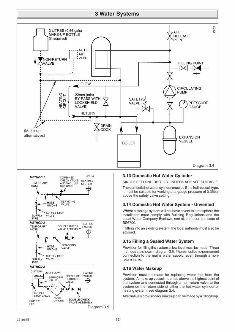
Remove the blue and red electrical connections from the fan,see diagram 5.3.
Break the air pressure switch tube connections from the fan,see diagram 5.3.
Remove the fan assembly by removing the screws and slidingout, see diagram 5.3. Take care not to damage the gasket.
Slacken, but do not remove, the flue hood securing screws, seediagram 5.4.
5 Boiler Installation
18221966B
5.3 Water Circulation SystemComplete the water connections to the boiler.
Fill, vent and flush system.
Check for any leaks and put right.
5.4 Safety Valve DischargeFit a suitable discharge pipe to the safety valve and route itoutside the building so that any discharge can be seen but willnot cause injury to person, damage to property or any electricalinstallation.
5.5 Gas ConnectionMake the gas connection to the Rc 1/2in gas service cock, seediagram 5.5.
Check for leaks using a suitable leak detection fluid.
The whole of the gas installation, including the meter, should beinspected, tested for soundness and purged in accordance withthe current issue of BS6891 and in IE the current edition of I.S.813 "Domestic Gas Installations".
Diagram 5.5Diagram 5.3
CLEAR
RED
FLUE HOODSECURINGSCREW (4)
FAN SECURINGSCREWS
FANASSEMBLY
AIR PRESSURESENSING PIPESCLEAR
ELECTRICALCONNECTIONS
Diagram 5.4
FLUE HOODSECURING SCREWS (4)
FANSECURINGBRACKET
FLUEHOOD
GAS SERVICE COCK(SHOWN OFF)
UNION NUT
4287
4289
4288
5 Boiler Installation

19 221966B
NOTE: If external flue fixing is required start at 6.2.
6.1 Flue Fixing - InternalNOTE: Use of the optional wall liner kit is required.
Place the flue assembly into the hole. Check that the flueterminal is correctly positioned and is the distance required fromthe outside wall face, see diagram 6.1.
Position flue elbow gasket and secure the flue assembly to theboiler using the dogpoint screws, see diagram 6.2.
Make sure of the correct fitting of the flue to the boiler.
Now continue at Section 6.3.
6.2 Flue Fixing - ExternalRemove the flue elbow from the air duct/terminal and flue duct,by removing and keeping, the securing screw(s).
From outside place the air duct/terminal and flue duct assemblyinto the hole and make sure that the flue terminal is correctlypositioned and is the distance required from outside wall face,see diagram 6.1.
Position flue elbow gasket and secure the flue elbow to theboiler using the dogpoint screws, see diagram 6.2.
Make sure of the correct fitting of the flue to the boiler.
Pull the flue duct forwards and engage onto the flue elbow.
Push the air duct back into the wall to the dimension shown indiagram 6.3.
Important, the flue duct will become disengaged should thedimension be any greater than shown.
Hold the flue duct onto the flue elbow, then, secure the flue ductto the flue elbow, see diagram 6.3.
Pull the air duct back to engage with
the flue elbow and secure/seal.
6.3 All Flue InstallationsFit the fan to the flue elbow spigot and secure with the screwspreviously removed.
Reconnect the blue and red electrical connections to the fan,the polarity of the connections is not important.
Reconnect the air pressure switch tubes as shown in diagram5.3.
Secure the flue hood, see diagram 5.4.
Diagram 6.1
Diagram 6.3
152 DIACORE
DRILLEDHOLE
58
OUTSIDEWALL FACE
FLUETERMINAL
AIRDUCT
7005
✽ 30mm
WALL FACE
FLUEELBOW
FLUE DUCT
✽30mm
FLUEDUCT/ELBOW
3mm Drill
SealingTape
✽ Maximum dimension! Otherwise the flue duct willbecome disengaged.
Diagram 6.2
GASKETFLUE ELBOW
SECURINGSCREW (4)
0181
M42
90
6 Flue Fixing

20221966B
7.1 Control Box RemovalRemove the electrical control box securing screws, see diagram7.1. Slide the box forwards and release, hook it onto the lipbracket at the front, see diagram 7.1.
7.2 Electrical ConnectionWARNING: This boiler must be earthed.
Take care not to damage any internal wiring and capillaries.
Take the plastic cable retaining clip, from the loose items pack,peel off the backing paper and position it in a suitable place tosecure the incoming cable.
Using heat resistant (to 85oC) cable of at least 0.75mm2 (24/0.2mm) to the current issue of BS6500 Table 16 and of suitablelength, thread through the cable clamps, secure into the plasticclips and connect to appropriate terminals, see diagram 7.2 and11.5.
Standard colours are, brown - live (L), blue - neutral (N) andgreen and yellow - earth (E).
Make sure the cable is suitably secured.
When making connections, make sure that the earth conductoris made of a greater length than the current carrying conductors,so that if the cable is strained the earth conductor would be thelast to become disconnected.
NOTE: Open Vented Water Systems ONLY.
Bridge terminals K1 and K2.
7.3 Pump ConnectionThe pump must be connected directly to the control box, asshown in diagram 7.2, threading the cable through the cableclamp in the side of the control box.
7.4 External ControlsAny external controls must only be wired to interrupt the red linkbetween terminals SL and 9.
Make sure that the supply cable and all external cables aresecured and away from hot surfaces.
7.5 TestingChecks to ensure electrical safety must be carried out by acompetent person.
After installation of the system, preliminary electrical systemchecks as below should be carried out:
1. Test insulation resistance to earth.
2. Test earth continuity and short circuit of all cables.
3. Test the polarity of the mains.
The installer is requested to advise and give guidance to theuser of the controls scheme used with the boiler.
Diagram 7.2
Diagram 7.1
SECURINGSCREWS (2)
LIP BRACKET
MAINSCABLE
CABLECLAMPS
MAINSCABLE
✽REDLINK
✽ Remove red link between 9 & SL when fittinga time control etc (If no switch is fitted, link willmake the circulation pump run constantly).
PUMPCABLE
PUMPCABLE
NOTE: Bridgeterminal K1 & K2on an OpenVented Systemonly
IGNITION LEAD
9079
4136
7 Electrical Connectors

21 221966B
Please ensure the "Benchmark" logbook is completed and leftwith the user.
8.1 All SystemsCommissioning should be carried out by a competent personin accordance with the current issue of BS6798.
Do not operate the boiler wthout water.
Make sure that the system has been thoroughly flushed out withcold water without the pump in place.
Refit the pump, fill the system with water, making sure that allthe air is properly vented from the system and pump.
Before operating the boiler check that all external controls arecalling for heat.
8.2 Sealed Water Systems OnlyFlush the whole system with cold water without the pump inplace. Refit the pump and fill until the pressure gauge registers2.7bar (40lbf/in2). Clear any air locks and check for watersoundness.
Check the operation of the safety valve, by allowing the waterpressure to rise until the valve opens. The valve should openwithin +/-0.3bar (+/-4.3lbf/in2) of the preset pressure. Wherethis is not possible conduct a manual check and test.
Release cold water to initial system design pressure.
The set pointer on the pressure gauge should be set to coincidewith the indicating pointer.
8.3 Initial Lighting and TestingCAUTION: This work must be carried out by a competentperson, in accordance with the current issue of BS6798.
Make sure that all naked lights and cigarettes are out.
Identify the controls by reference to diagram 8.1.
Check that the boiler is isolated from the electrical supply.
Make sure that the control thermostat is turned to “O” the “Off”position.
Turn boiler gas service cock “On”.
Test the pilot supply tube and its connection for gas soundnessas follows:
Disconnect the ignition lead from the PCB, see diagram 7.2.
Remove the combustion chamber front, see diagram 8.2.
WARNING: The fan operates on mains voltage, terminals willbecome live.
Turn the electrical supply on and check that all remote controlsare calling for heat.
Check that the pump is circulating water through the system.
To complete the test it is necessary to operate the boiler withoutits case, but UNDER ALL OTHER CIRCUMSTANCES thecase must be correctly fitted and sealed.
Turn the control thermostat knob fully clockwise and the fan willwork.
NOTE: There will be no sparks at the pilot. Take care and lightthe pilot with a match.
Test the pilot supply and connections for gas soundness, usinga suitable leak detection fluid.
Very cold weather may delay the operating sequence.
The pilot rate is preset and must not be adjusted.
The step adjustment screw must not be touched.
The pilot flame length should be as shown in diagram 8.3.
Turn the control thermostat knob to “O” and isolate the boiler
Diagram 8.1
GAS SERVICE COCK(SHOWN OFF)
Diagram 8.2
SETTINGPOINT
OVERHEATSAFETYCUT-OFF
CONTROLTHERMOSTAT
COMBUSTIONCHAMBERFRONT PANEL VIEWING
WINDOW
SECURINGSCREW
CLEANING PLATE SECURINGSCREW (8)
4291
4292
8 Commissioning
from the electrical supply.
Fit the combustion chamber front.
Reconnect the ignition lead to the PCB.
For future reference, stick the self adhesive arrow indicator tothe data label, against the rating that the boiler is going to be setto. The arrow is in the loose items pack.
Loosen the main burner pressure test point screw and connecta suitable pressure gauge, see diagram 8.4.
Make sure that any remote controls are calling for heat.
Switch on/connect the electrical supply to the boiler and heatingsystem, neon 1 will light.

22221966B
8.4 Testing - ElectricalTurn the control thermostat knob fully clockwise to the maximumsetting, which is about 82oC (180oF), neon 2 will light.
The lighting sequence is automatic as follows:
The fan operates
The Spark ignition operates
The pilot solenoid opens
The pilot burner lights
The ignition spark stops
The main solenoid opens
and after a short period of time the main burner will light, lookthrough viewing window, see diagram 8.2.
The main burner will stay alight until switched off, either by thecontrol thermostat or a remote system control.
To make sure that the flame supervision device is workingcorrectly the following should be done:
Very cold weather may delay the operating sequence.
1. With the main burner alight, turn the gas service cock “Off”,see diagram 8.1.
After a short period the main burner and pilot will go out.
2. The correct working of the flame supervision device is shownby neon 4 going out within 10 seconds and the ignition startingup.
Neons 1, 2, and 3 should stay alight.
3. If the above does not happen, refer to fault finding Section11.1.
4. To carry on turn the gas service cock “On”, see diagram 8.1.
When the boiler switches “Off”, both the pilot and the mainburner go out. The automatic lighting sequence will work againwhen heat is required.
8.5 Testing - GasWith the boiler on proceed as follows:
The whole of the gas installation, including the meter, should beinspected, tested for soundness and purged in accordance withthe current issue of BS6891 and in IE the current edition of I.S.813 "Domestic Gas Installations".
Check the main burner gas pressure at least 10 minutes afterthe boiler has lit, refer to Data Label.
If necessary adjust the gas pressure to obtain the requiredsetting turning the screw clockwise, to decrease pressure, seediagram 8.4.
Should any doubt exist about the gas rate, check it using the gasmeter test dial and stop watch, at least 10 minutes after theburner has lit, making sure that all other gas burning appliancesand pilot lights are off.
Turn the control thermostat knob fully anticlockwise to “O”.Remove the pressure gauge from the test point and refit screw,making sure a gas tight seal is made.
When the control thermostat is turned to “Off” position, by hand,wait at least 30 seconds before turning “On” again.
There may be an initial smell given off from the boiler, this isquite normal and will disappear after a short period of time.
Refit the electrical controls box, see diagram 7.1.
NOTE: The neon indicators on the printed circuit board are anaid to fault finding, for details refer to Section 11.
Diagram 8.3
10 to 20mm FLAME LENGTH
NOTE:PILOT SHIELDREMOVED FORCLARITY
ULTIMATE 120FF
SPARK GAP2.5 to 4mm
NOTE:PILOT SHIELDREMOVED FORCLARITY SPARK GAP
2.5 to 4mm
ULTIMATE 100FF
4293
(2)
4139
4293
(1)
10 to 20mm FLAME LENGTH
4146
Neon 4 will light}} Neon 3 will light
8 Commissioning

23 221966B
8.6 Testing - Open VentedAllow the system to reach maximum working temperature andexamine for water leaks.
There should be no undue noise in the system and no pumpingover of water or entry of air at the open vent above the feed andexpansion cistern.
All systems. The boiler should be turned off and the systemdrained off as rapidly as possible, whilst still hot.
8.7 Adjustment - Fully Pumped Open Ventedand Sealed Water SystemsWhen commissioning the system the boiler should first be firedwith the bypass fully closed on full service, that is, centralheating and domestic hot water. Adjust the pump to the systemdesign setting then balance the system. Having achieved asatisfactory condition operate the boiler with the bypass fullyclosed on minimum load, normally this will be central heatingonly with one radiator in the main living area operating. Thebypass valve should be gradually opened to achieve atemperature difference no greater than 20oC between the flowand return.
UNDER NO CIRCUMSTANCES SHOULD THIS VALVE BELEFT IN THE FULLY CLOSED POSITION.
8.8 Sealed Water System ONLYAdjust system to initial design pressure. The set pointer on thepressure gauge should be set to coincide with the indicatingpointer.
Diagram 8.4
GASPRESSUREADJUSTMENTSCREW
MAIN BURNERPRESSURE TEST SCREW
NOTE:DO NOT ADJUST ANYOTHER SETTING SCREWS
MULTI-FUNCTIONALCONTROL
4294
8 Commissioning
Diagram 8.6
Diagram 8.5
CONTROLSCOVER
SLIDERS
SIDESEAL
TOPSEAL
NUT
FRONTCOVER
WASHERWINGNUT
RETAININGCLIP
4295
4140
8.9 Thermostatic Radiator ValvesIf thermostatic radiator valves are fitted care must be taken toensure that an adequate flow rate through the boiler when theyclose, refer to the current issue of BS7478 for guidance.
24221966B
Instruct and demonstrate the safe and efficient operation of theboiler, heating system and domestic hot water system.
Advise the user, that to ensure the continued efficient and safeoperation of the boiler it is recommended that it is checked andserviced at regular intervals. The frequency of servicing willdepend upon the particular installation and usage, but in generalonce a year should be enough.
Draw attention, if applicable, to the current issue of the GasSafety (Installation and Use) Regulations, Section 35, whichimposes a duty of care on all persons who let out any propertycontaining a gas appliance in the UK.
REMEMBER: When replacing a part on this appliance, use onlyspare parts that you can be assured conform to the safety andperformance specification that we require. Do not usereconditioned or copy parts that have not been clearly authorisedby Glow-worm
NOTES:. To ensure the continued efficient and safe operationof the boiler it is recommended that it is checked and servicedas necessary at regular intervals. The frequency of servicingwill depend upon the particular installation conditions andusage, but in general once a year should be enough.
It is the Law that any servicing is carried out by a competentperson.
Before servicing turn off the gas and isolate the electrical supplyto the boiler.
After completing a service always test for gas soundness andcarry out functional check on controls.
Unless stated otherwise all parts are replaced in the reverseorder to removal.
10.1 AccessRefer to diagram 8.6 and slide controls cover forward and off.
Remove the outer case, see diagram 8.5.
NOTE: As an aid to servicing the air pressure switch tubeconnections can be used to obtain a products of combustionreading.
Remove the RED tube from the connection on the air pressureswitch and insert the analyser probe into the tube.
Switch on the electrical supply to operate the fan and turn on thegas supply.
On completion of the test switch off the electrical supply and thegas supply and reconnect the red tube to the air pressureswitch.
Diagram 10.1
SECURING NUT ANDSHAKEPROOF
WASHER
PILOT PIPEUNIONCONNECTOR
ELECTRODE ANDLEAD ASSEMBLY
4094
8.10 Operational Checks and CompletionAdjust the control thermostat and any system controls to theirrequired settings.
Do not attempt to adjust the thermostat calibration screw.
Operate the boiler again on full service and check that thebalancing is satisfactory, making adjustments as necessary.
Fit the front cover by hooking it under at the top and securingwith the screws previously removed, see diagram 8.5.
Fit the controls cover by hooking into the sliders and pushing itback as far as it will go, see diagram 8.6.
8 Commissioning
9 Instructions to the User
10 Servicing
Testing Flue Gases: If any doubt exists that the flue productsare not exhausting correctly, investigate by use of a gasanalyser (FGA).
8.11 Protection against FreezingIf the boiler is to be out of use for a period of time during severeweather conditions we recommended that the whole of thesystem, including the boiler, be drained off to avoid the risk offreezing up.
It is the Law that servicing is carried out by a competentperson.
Advise the user of the precautions necessary to prevent damageto the system and the building in the event of the heating systembeing out of use during frost and freezing conditions.
Reminder, leave these instructions and the ‘Benchmark’ logbookwith the user.
For IE, it is necessary to complete a "Declaration of Conformity"to indicate compliance to I.S.813. An example of this is given inthe current edition of I.S.813.

25 221966B
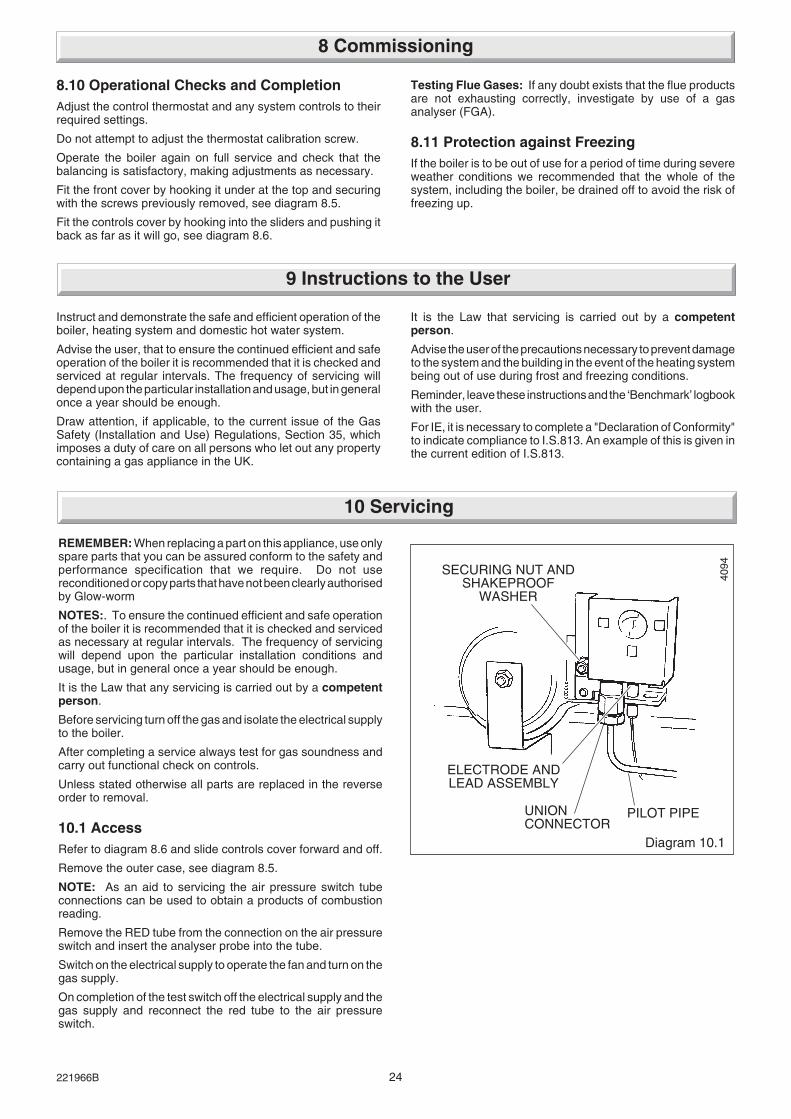
10.2 Cleaning Heat Exchanger and BurnerDisconnect the air pressure tubes, see diagram 5.3.
Remove the blue and red electrical connections from the fan,see diagram 5.3.
Remove the fan taking care not to damage the gasket, seediagram 5.3.
Remove the flue hood, see diagram 5.4.
Remove the combustion chamber cover, see diagram 8.2.
Remove the cleaning plate from the combustion chambercover, see diagram 8.2.
Disconnect the pilot pipe union connector and pilot burner,securing nut and shakeproof washer together with the pilotshield. Remove the pilot burner assembly taking care not todamage the electrode and lead assembly, see diagram 10.1.
Remove the securing screw from the burner support bracket,see diagram 10.2.
Remove the main burner from the main injector at the rear.Raise the burner up and forward, easing the pilot pipe down, toclear, take care not to damage the combustion chamber insulationor the pilot pipe.
Use a vacuum cleaner or suitable stiff brush to clean the burnerthoroughly, making sure that all the burner ports are clear andunobstructed.
Place a sheet of paper in the base of the combustion chamber.
100 FF ONLYRemove the baffles, see diagram 10.3.
If a vertical or flue bend systems, using corrugated bends, seeFlue Kit Installations, has been fitted then the TOP FLUEBAFFLES will have been REMOVED.
NOTE: When replacing the bottom three baffles, the two halfand one whole baffle, make sure that they are positioned withthe mark “100” to front of appliance as shown in diagram 10.3.
120 FF ONLYRemove the baffles, see diagram 10.4.
NOTE: When replacing the bottom baffle, make sure that it ispositioned with the word “Bottom” to front of appliance as shownin diagram 10.4.
Continued-The heat exchanger can now be cleaned, paying particularattention to the gap between the fins, with a suitably sized semi-stiff brush, using the cleaning plate, as shown in diagram 10.5,to protect the rear insulation panel.
Remove the paper together with any debris.
10.3 Main InjectorWith the main burner removed the main injector can be inspectedand cleaned as necessary, see diagram 10.6.
If removing for cleaning do not use a wire or sharp instrumenton the hole.
Use a little suitable sealant on the external thread when refittingto make sure a gas tight seal is made.
NOTE: On refitting and after cleaning the heat exchanger makesure the burner is fitted correctly, that is, located on the maininjector and horizontal.
Diagram 10.2
SECURINGSCREW
BURNERSUPPORT BRACKET
4296
10 Servicing
Diagram 10.4
BAFFLE (4)
HEATEXCHANGER
9642
120FF only
Diagram 10.3
BAFFLE (6)
HEATEXCHANGER
9642
100FF only

26221966B
10.4 Electrode, Pilot Burner and Pilot InjectorClean the pilot burner and electrode.
100FF Model Only. To remove the electrode release the springclip, see diagram 10.7.
120FF Model Only. To remove the electrode remove thesecuring screw, see diagram 10.7.
When removing and replacing the pilot injector from the pilotburner take care not to damage the electrode, see diagram 8.6,clean the injector by blowing through it.
Check that the spark gap is as shown in diagram 8.3.
10.5 Operational ChecksAfter completing a service and before fitting the case, checkcondition of the case seal and renew if necessary.
Examine the flue hood and terminal to make sure they are cleanand clear of obstructions.
Light the boiler and carry out the functional checks as describedin Section 8.
Testing Flue Gases: If any doubt exists that the flue productsare not exhausting correctly, investigate by use of a gasanalyser (FGA).
Diagram 10.5
Diagram 10.6
PILOTBURNER
SPRINGCLIP
ELECTRODE
PILOTINJECTOR
Diagram 10.7
PILOTBURNER
PILOTINJECTOR
SEMI STIFFNYLON BRISTLESCLEANING BRUSH
380m
m M
IN
40mm
20mm
50mm
CLEANING PLATE
MAIN BURNERINJECTOR
ELECTRODE
SECURINGSCREW
ULTIMATE 120FF
ULTIMATE 100FF
4306 42
99
4298
4299
S
10 Servicing

27 221966B
11.1 ElectricalIMPORTANT: On completion of the Service/Fault Finding taskwhich has required the breaking and remaking of the electricalconnections, the earth continuity, polarity and short circuit andresistance to earth checks must be repeated using a suitablemultimeter.
Refer to diagrams 11.1 to 11.5 for the relevant fault finding andwiring information.
11.2 Electrical Supply FailureFailure of the electrical supply will cause the burner to go out.
Operation will normally resume on the restoration of the electricalsupply. If the burner does not relight after and electrical failurethe overheat device may need resetting.
Remove the control cover, see diagram 8.6 and push the resetbutton on the front of the control box, see diagram 8.1.
If the cutoff operates at any other time press the reset button andthe burner should relight. If the fault persists refer to the faultfinding chart.
Diagram11.1
Neon Indicators - An Aid to Fault FindingTHE NEON INDICATORS ARE AN AID TO FAULT FINDING ONLY. FAILURE OF ANY OF THE NEON INDICATORS DOES NOT WARRANT THE
REPLACEMENT OF AN OTHERWISE SATISFACTORY PRINTED CIRCUIT BOARD (PCB).
Is neon 1 lit? Fault with mains supply or PCB fuse
Ignition, pilot or flame proving fault -see detailed fault finding chart.
Air flow proving fault - that is fan or air pressureswitch - see detailed fault finding chart.
Multi-functional control/harness problem -see detailed working?fault finding chart.
YES
YES
YES
YES
YES
NO
NO
NO
NO
NO
Low water pressure (sealed system),Overheat cut off device tripped or thermostat,overheat cut off device faulty.- see detailed fault finding chart.
Is neon 2 lit?
Is neon 4 lit?
System satisfactory
Is neon 3 lit?
Is main burner operating?
NEONINDICATORS
4120
11 Fault Finding

28221966B
Is there 230V~ between SL and
N and between L and N ?
Diagram 11.2
Is neon 1 lit?
YES YES
YES
NO
Correct power supply problem.
NOYESReplace thermostat.
NO
YES
NOIs neon 3 lit?
Is there 230V~ between
"N/C" on air pressure switch and N ?
YES
Check yellow cable between printed circuit boardand air pressure switch.If satisfactory replace printed circuit board.
YES
NOIs there 230V~ between "C" on air pressureswitch and N ? Replace air pressure switch.
Does fan run?
YES
NO
NOYESReplace fan.
YESReplace printed circuit board.Does fan Hunt?
NO Inspect air tubes for leaks, kinks and correct fitting. Ifsatisfactory replace faulty air pressure switch.
NO
Is there 230V~between "N/O" on airpressure switch and N ?
YES
NO NO
Is there 230V~ between yellow connection onoverheat device and N ?
Is there 230V~ between motor connections on fan?
Isolate electrical supply test fanharness continuity.If satisfactory replace printed circuit board.
Before detailed checking of electrical components ensure that remote controls are calling for heat. Check the gas supply is free of obstructions and purged of air. Checkthe overheat cutoff has not operated. For fully pumped systems only. Isolate the electrical supply and physically check ALL cables, connections and the printed circuitboard fuse. Check the air tubes to the air pressure switch. Switch on the electrical supply and check for correct polarity. Turn the control thermostat to its maximumsetting. Also check fuses.
Check overheat reset.If satisfactory replace overheat device.
Is neon 2 lit?NO
Is there 230V~ between K1 and N ?
YES
YES
Check 0.2 Bar of water pressure is available atboiler, If ok, Replace water pressure switch.
NO
Is there 230V~between "N/C" on thermostat and N ?
NO
NOInspect electrode lead /connectionfor poor contact. Check electrical supply polarity andcorrect if necessary.If satisfactory replace printed circuit board.
With pilot lit does spark stop?
NOReplace main solenoid
YES
Replace multi-functional control.
YES
Is Neon 4 lit?
NO
Does main burner light?
System satisfactory
YES
NO
YES
YES
Is there a spark at pilot burner? Check lead continuity and inspect electrode andlead for damage.
Check for pilot jet blockage, incorrect electrodeadjustment isolate supply. Remove plug frommultifunctional control. Check continuity of pilotsolenoid between EV1 and COM, continuity OK?
Does pilot light?NO
Replacemultifunctionalcontrol
Replace pilotsolenoid.
NOYES
Isolate supply. Remove plug from themultifunctional control. Check continuity ofmain solenoid between EV2 and COM.Continuity OK?
YES
M A I N T E R M I N A L S T R I P
C O N T R O L T H E R M O S T A T
11 Fault Finding
29 221966B
FUSETYPE F1 & F2(F1A)
AIR PRESSURE SWITCH CONNECTIONS
SPARKELECTRODE
WATER PRESSURESWITCH
O/H CUTOFF
CONTROLSTAT
FAN
AIRPRESSURESWITCH
PILOTSOLENOID
MAINSOLENOID
N
N
N
N
N
N
N
(N/O) (C)
(N/C)
L
K2
K1
N/C
C
N
Nb
w
g
w
br
p
yy
r b
r
bkb
y
br b
bbkb
KEYbk BLACKbr BROWNb BLUEp PURPLEg GREY
or ORANGEw WHITEr REDy YELLOW
SL
MAIN TERMINAL STRIP CONNECTIONS
CONTROL THERMOSTAT CONNECTIONS
PRINTED CIRCUIT BOARD CONNECTIONS
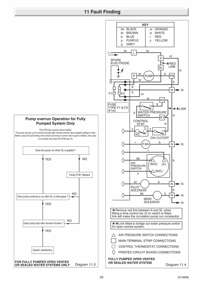
FULLY PUMPED OPEN VENTEDOR SEALED WATER SYSTEM
PN
9
P
L
PUMPbr b
brbr
b
b
*RED LINK
*Remove red link between 9 and SL whenfitting a time control etc (if no switch is fitted,link will make the circulation pump run constantly)
**LInk fitted to bridge out water pressure switchfor open vented system.
F1 F2
or
or
or
p
**LINK
Diagram 11.4
11 Fault Finding
Diagram 11.3
Pump overrun Operation for FullyPumped System Only
YES NO
Faulty PCB. Replace
Does pump stop after several minutes ?
YES
Does the pump run when SL is applied ?
Does pump continue to run after SL is interrupted ?NO
NO
System satisfactory.
YES
The PCB has a pump overrun facility.The pump should run for several minutes after remote controls have stopped calling for heat.Before using the fault finding chart ensure all wiring is correct and in good condition, the pump
is not faulty and check the PCB fuse F2.
FOR FULLY PUMPED OPEN VENTEDOR SEALED WATER SYSTEMS ONLY

30221966B
11 Fault Finding
Diagram 11.5
SWITCH CONTROL,TIME SWITCH,PROGRAMMER ETC.(if fitted)
✽ Remove red link between 9 and SL when fitting a time control etc (If no switch is fitted, link will make the circulation pump run constantly)
b
r
ry
AIRPRESSURESWITCH
WATERPRESSURESWITCH
MULTI-FUNCTIONALCONTROL
FAN
PLUG
ELECTRODE
SEQUENCEBOARD
CHASSIS EARTH g/y
p
bbr
CHASSISEARTH
g/y
p
or
b
w
y
y
CONTROLTHERMOSTAT
OVERHEATCUTOFF
brLN
E
NLE
b
bbr
g/y
br
C
NC
g/y
w
230~50HzPERMANENTMAINSSUPPLYFUSEDAT 3-AMP
CIRCULATIONPUMP
w
FUSES F1 &F2 (F1A)
K2
K1
PN
SL
P
9
N
L
NOTE:-Bridge out Water Pressure Switchbetween K1 & K2 if using open ventedsystem
3 PLUGS
✽ See Note
g/y
NC
bk
NO
C
pg
FULLY PUMPED OPEN VENTED ORSEALED WATER SYSTEM
9075
g
b - BLUEbk - BLACKbr - BROWNg/y - GREEN/
YELLOWr - RED
y - YELLOWw - WHITEp - PURPLEg - GREY
KEY
p
g/yg/y
r

31 221966B
NOTE: Replacement of parts must only be carried out by acompetent person.
Before replacing any parts isolate the boiler from the electricalsupply and turn the gas supply off at the gas service cock,indicator slot to be vertical.
Unless stated otherwise, all parts are replaced in the reverseorder to removal.
After replacing any parts always test for gas soundness and ifnecessary carryout functional check of controls.
12.1 AccessGain access as Section 10.1.
12.2 Control Thermostat - diagram 12.1 and12.2Remove and support the electrical control box, refer to Section7.1.
Remove the control knob. Remove the electrical connectionsfrom the control thermostat body.
Release the control thermostat body be unscrewing the twoscrews and shakeproof washers in the front of the control box.
Remove the split pin and withdraw the thermostat phial from itspocket. Release the capillary from the base and the plasticretaining clip then remove it from the split grommet. Release thecapillary from its clips. Remove the thermostat complete fromthe boiler.
Reassembly NOTE: When refitting the thermostat make surethat the thermostat phial is covered with heat sink compoundthen fully inserted into the phial pocket and that the capillary iswithin the gland seal, see diagram 12.2. Remake the electricalconnections. There must be no kinks or sharp bends in thecapillary.
12.3 Overheat Cutoff Device - diagram 12.1,12.2 and 12.2ARemove and support the electrical control box, refer to Section7.1.
Remove the overheat cutoff electrical connections.
Disconnect the air pressure switch plug from the PCB.
Remove the locking nut from the overheat cutoff.
Release the capillary from the retaining clips then remove itfrom the split grommet.
Remove the split pin and then the phial.
When refitting use the heat sink compound supplied.
12 Replacement of Parts
Diagram 12.1
ELECTRICALCONNECTIONS
YELLOW C &NC
CONTROLTHERMOSTAT
SHAKEPROOFWASHERS ANDSCREWS
CONTROLKNOB
RETAININGCLIP
SPLITGROMMET
LOCKNUT
ELECTRICALCONNECTIONS
9076

32221966B
12.4 Control Board (PCB) - diagram 12.2ARelease the control box, refer to Section 7.1.
Disconnect the three electrical plugs and ignition lead.
Release the cables from the plastic retaining clip, then disconnectthe cables from the PCB to the main terminal strip, controlthermostat and earth connection.
Release the main terminal strip and plastic label.
Carefully pull the board away from its supports.
When refitting refer to wiring diagram 11.5.
12.5 Pilot Burner and Pilot InjectorProceed as Section 10.2 and 10.4.
12.6 ElectrodeProceed as Section 8.3 and 8.5.
Gain access as Section 7 to remove lead from control box.
12.7 Multifunctional Control - diagram 10.3Disconnect the pilot supply by unscrewing the tubing nut at themultifunctional control.
120FF ONLY. Take care as there is a restrictor in the pilot pipe.
Disconnect the electrical plug.
Support the multifunctional control, remove the four extendedscrews from the flanged connections at the left and right handside.
Remove and discard the original “O” rings from the flangedconnection and fit the new “O” rings supplied, into recess,before fitting the replacement multifunctional control.
After assembly test for gas soundness and purge in accordancewith the current issue of BS6891 or in IE, the current edition ofI.S.813 "Domestic Gas Installations".
12.8 Solenoid - diagram 12.3Remove the electrical plugs from the multifunctional control.Remove the securing screw and then the solenoid assembly.
Diagram 12.2 Diagram 12.2A
OVERHEATCUTOFFELECTRICALCONNECTION"WHITE"CABLE
PHIALPOCKET
THERMOSTATPHIAL
SPLITPIN
RETAININGCLIP
OVERHEATCUTOFFDEVICEPHIAL
SPLITPIN
CONTROLTHERMOSTATELECTRICALCONNECTIONNO.6"YELLOW"CABLE
ELECTRICALCONNECTIONBLUE CABLE "N"
ELECTRICALCONNECTIONBLUE CABLE "SL"
ELECTRICALPLUGS
PLASTICRETAININGCLIP
MAINTERMINALSTRIP
CHASSISEARTHCONNECTION
EARTHCONNECTION
SECURINGSCREW (2)
IGNITIONLEAD
4301
5756 ELECTRICAL PLUGS
SUPPORTPOST (4)
4090
12 Replacement of Parts

33 221966B
12.9 Main BurnerRemove the main burner as Section 10.2.
12.10 Main InjectorRemove the main burner as Section 10.2.
Remove the main injector as Section 10.3.
12.11 Insulation - diagram 12.4
Combustion Chamber FrontRemove the retaining screw then the insulation.
SidesSlide the insulation out.
12.12 Viewing Window - diagram 12.5Remove the old self adhesive aluminium foil gasket and the oldmica window. Replace with a new mica window. Peel off thebacking paper and secure with new self adhesive aluminium foilgasket, see diagram 12.5. Ensure no air bubbles are trappedunderneath the foil.
12.13 Air Pressure Switch - diagram 12.6Release the control box as Section 7.1
Remove the pressure tubes and the electrical connections fromthe PCB, release the screws and remove the switch.
When fitting the replacement make sure that the plastic tubesand electrical connections are made as shown in diagram 11.5and 12.6.
Diagram 12.3
SOLENOIDS
ELECTRICALPLUG
SECURINGSCREW
EXTENDEDSCREW(8 off)RESTRICTOR
(120FF Only)
PILOT PIPETUBING NUT
4302
12 Replacement of Parts
Diagram 12.4
SECURING SCREW
FRONTINSULATION
SIDE INSULATION43
03
Diagram 12.5
SELF ADHESIVEALUMINIUM FOILGASKET
MICA WINDOW
PEEL OFFBACKINGPAPER
OPENING(INSIDE FACEOF THE BOILERFRONT COVER)
7907

34221966B
13.1 Part IdentificationThe key number in the diagram and the first column of the listwill help to identify the spare part.
13.2 OrderingWhen ordering any spare part, please quote the part numberand the description from the list together with the model nameand serial number information from the data label. The datalabel is positioned at the bottom right hand side of case.
If ordering from British Gas also quote the GC number of theappliance from the data label and the GC number of the sparepart, from the list.
Diagram 12.6
RED
CLEARAIR PRESSURESWITCH TUBES
SECURINGSCREWS
AIRPRESSURE
SWITCHELECTRICALCONNECTIONS CONTROL
BOX
Diagram 12.7
9077
WATER PRESSURESWITCH
ELECTRICALCONNECTIONS
PURPLE
GREY
4304
12.14 Fan - diagram 5.3Remove the electrical connections and disconnect the airpressure tubes.
Remove the fan assembly securing screws.
Make sure that the earth connection is remade onto the new fanassembly.
The polarity of the other connections is not important.
12 Replacement of Parts
12.15 Water Pressure Switch - Sealed WaterSystem OnlyRelease the water pressure and drain, refer to Section 3.
Disconnect the electrical connections at the microswitch, seediagram 12.7.
Remove pressure switch.
On assembly, use new “O” ring, secure the water pressureswitch with locknut in the orientation shown as diagram 12.7.
Make up water loss and pressurise system, refer to“Commissioning”.
13 Spare Parts

35 221966B
Key No Part No Description GC Part No
1 800442 Multifunctional control 278 0212 208040 “O” ring 334 5923 205727 Injector - 100FF 278 1973 205726 Injector - 120FF 278 1964 203432 Pilot burner - 100FF 278 0234 203434 Pilot burner - 120FF E00 9985 2000801236 Mica Glass *********6 2000800529 Fan assembly - 100FF 278 1946 2000800532 Fan assembly - 120FF 278 1857 202626 Spark electrode and lead - 100FF 313 9987 202629 Spark electrode and lead - 120FF 278 2388 K3580 Clip - electrode 390 9839 800850 Thermostat - control *********10 202232 Air pressure switch - 100FF 278 23910 202201 Air pressure switch - 120FF 313 99211 800275 Control knob 313 60912 2000800656 Water pressure switch *********13 204212 “O” ring 281 34314 202015 Fuse 334 75015 900847 Control board PCB *********16 800272 Overheat safety cutoff 313 606
13 Spare Parts
Diagram 13.1
2
1
4 (120FF) 4 (100FF)
5
11
8
6 (100FFILLUSTRATED)
9
7(120FF)
7(100FF)
13
1210(100FF ILLUSTRATED)
14 1516
9042
3(100FFILLUSTRATED)

36221966B
Because of our constant endeavour for improvement, details may vary slightly from those shown in these instructions.