Embed Size (px)
Citation preview


Produkte
Products
Prüfbericht - Nr.:
Test Report No. 10043715 001 Seite 2 von 48
Page 2 of 48
TEST SUMMARY 5.1.1 ANTENNA REQUIREMENT
RESULT: Passed
5.1.2 PEAK OUTPUT POWER
RESULT: Passed
5.1.3 20DB BANDWIDTH
RESULT: Passed
5.1.4 99% BANDWIDTH
RESULT: Passed
5.1.5 CONDUCTED SPURIOUS EMISSIONS AND FREQUENCY BAND EDGE MEASURED IN
100KHZ BANDWIDTH
RESULT: Passed
5.1.6 SPURIOUS EMISSION
RESULT: Passed
5.1.7 FREQUENCY SEPARATION
RESULT: Passed
5.1.8 NUMBER OF HOPPING FREQUENCY
RESULT: Passed
5.1.9 TIME OF OCCUPANCY
RESULT: Passed
5.2.1 MAINS CONDUCTED EMISSIONS
RESULT: Passed
6.1.1 ELECTROMAGNETIC FIELDS
RESULT: Passed
Produkte
Products
Prüfbericht - Nr.:
Test Report No. 10043715 001 Seite 3 von 48
Page 3 of 48
Contents
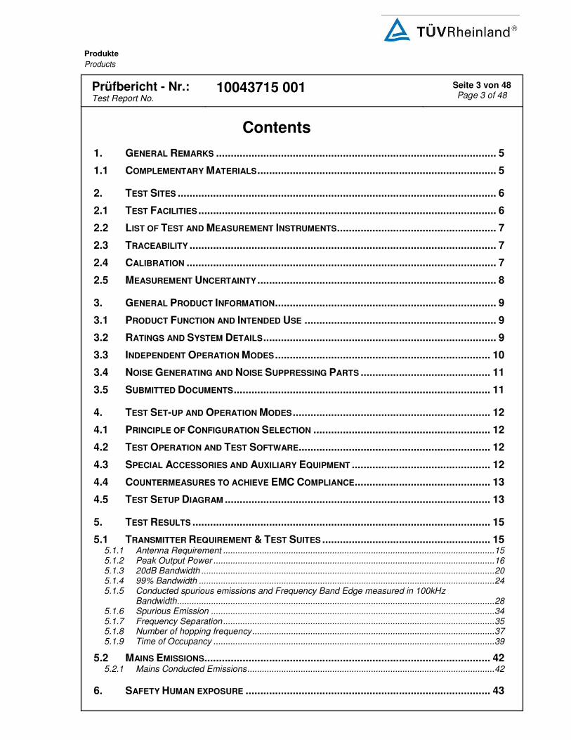
1. GENERAL REMARKS ............................................................................................... 5
1.1 COMPLEMENTARY MATERIALS ................................................................................. 5
2. TEST SITES ............................................................................................................ 6
2.1 TEST FACILITIES ..................................................................................................... 6
2.2 LIST OF TEST AND MEASUREMENT INSTRUMENTS ...................................................... 7
2.3 TRACEABILITY ........................................................................................................ 7
2.4 CALIBRATION ......................................................................................................... 7
2.5 MEASUREMENT UNCERTAINTY ................................................................................. 8
3. GENERAL PRODUCT INFORMATION ........................................................................... 9
3.1 PRODUCT FUNCTION AND INTENDED USE ................................................................. 9
3.2 RATINGS AND SYSTEM DETAILS ............................................................................... 9
3.3 INDEPENDENT OPERATION MODES ......................................................................... 10
3.4 NOISE GENERATING AND NOISE SUPPRESSING PARTS ............................................ 11
3.5 SUBMITTED DOCUMENTS ....................................................................................... 11
4. TEST SET-UP AND OPERATION MODES ................................................................... 12
4.1 PRINCIPLE OF CONFIGURATION SELECTION ............................................................ 12
4.2 TEST OPERATION AND TEST SOFTWARE................................................................. 12
4.3 SPECIAL ACCESSORIES AND AUXILIARY EQUIPMENT ............................................... 12
4.4 COUNTERMEASURES TO ACHIEVE EMC COMPLIANCE .............................................. 13
4.5 TEST SETUP DIAGRAM .......................................................................................... 13
5. TEST RESULTS ..................................................................................................... 15
5.1 TRANSMITTER REQUIREMENT & TEST SUITES ......................................................... 15
5.1.1 Antenna Requirement ................................................................................................................ 15
5.1.2 Peak Output Power .................................................................................................................... 16
5.1.3 20dB Bandwidth ......................................................................................................................... 20
5.1.4 99% Bandwidth .......................................................................................................................... 24
5.1.5 Conducted spurious emissions and Frequency Band Edge measured in 100kHz Bandwidth ................................................................................................................................... 28
5.1.6 Spurious Emission ..................................................................................................................... 34
5.1.7 Frequency Separation ................................................................................................................ 35
5.1.8 Number of hopping frequency .................................................................................................... 37
5.1.9 Time of Occupancy .................................................................................................................... 39
5.2 MAINS EMISSIONS................................................................................................. 42
5.2.1 Mains Conducted Emissions ...................................................................................................... 42
6. SAFETY HUMAN EXPOSURE ................................................................................... 43

Produkte
Products
Prüfbericht - Nr.:
Test Report No. 10043715 001 Seite 4 von 48
Page 4 of 48
6.1 RADIO FREQUENCY EXPOSURE COMPLIANCE ......................................................... 43
6.1.1 Electromagnetic Fields ............................................................................................................... 43
7. PHOTOGRAPHS OF THE TEST SET-UP ..................................................................... 44
8. LIST OF TABLES ................................................................................................... 48
9. LIST OF PHOTOGRAPHS......................................................................................... 48

Produkte
Products
Prüfbericht - Nr.:
Test Report No. 10043715 001 Seite 5 von 48
Page 5 of 48
1. General Remarks
1.1 Complementary Materials
All attachments are integral parts of this test report. This applies especially to the following appendix:
Appendix PI: Photo Documentation internal view (File Name: 10043715APPENDIX PI) Appendix PE: Photo Documentation external view (File Name: 10043715APPENDIX PE) Appendix D: Test Result of Radiated Emissions (File Name: 10043715APPENDIX D)
Test Specifications
The following standards were applied (in bold: product standards, otherwise: basic standards).
Table 1: Applied Standard and Test Levels
Radio FCC CFR47 Part 15: Subpart C Section 15.247 ANSI C63.4:2009, Public Notice DA 00-705 NCC Low-power Radio-frequency Devices Technical Regulations LP0002(2011)(100年6月28日)
Produkte
Products
Prüfbericht - Nr.:
Test Report No. 10043715 001 Seite 6 von 48
Page 6 of 48
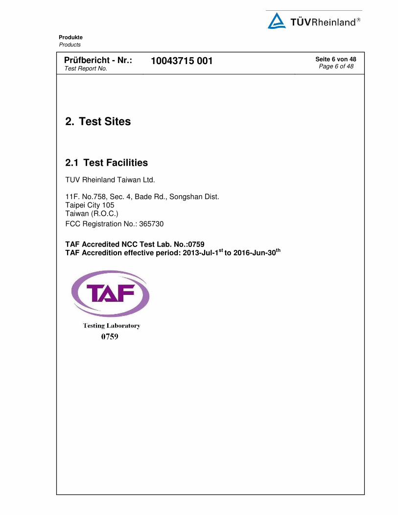
2. Test Sites
2.1 Test Facilities
TUV Rheinland Taiwan Ltd. 11F. No.758, Sec. 4, Bade Rd., Songshan Dist. Taipei City 105 Taiwan (R.O.C.)
FCC Registration No.: 365730
TAF Accredited NCC Test Lab. No.:0759 TAF Accredition effective period: 2013-Jul-1st to 2016-Jun-30th
Produkte
Products
Prüfbericht - Nr.:
Test Report No. 10043715 001 Seite 7 von 48
Page 7 of 48
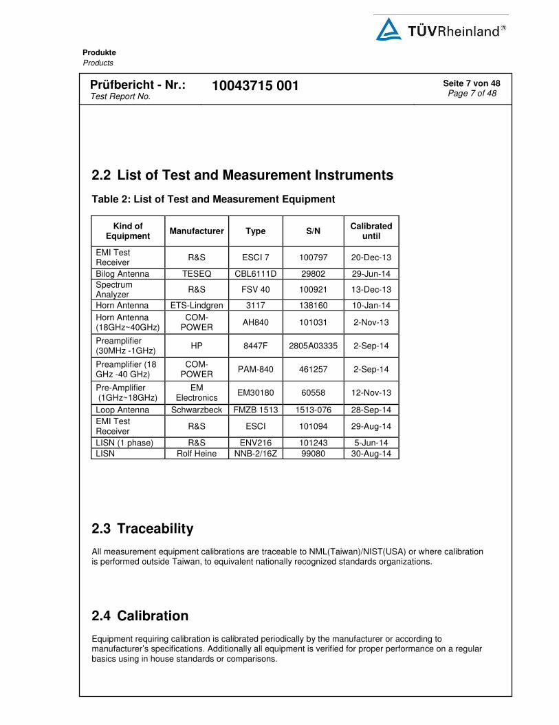
2.2 List of Test and Measurement Instruments
Table 2: List of Test and Measurement Equipment
Kind of Equipment
Manufacturer Type S/N Calibrated
until
EMI Test Receiver
R&S ESCI 7 100797 20-Dec-13
Bilog Antenna TESEQ CBL6111D 29802 29-Jun-14
Spectrum Analyzer
R&S FSV 40 100921 13-Dec-13
Horn Antenna ETS-Lindgren 3117 138160 10-Jan-14
Horn Antenna (18GHz~40GHz)
COM-POWER
AH840 101031 2-Nov-13
Preamplifier (30MHz -1GHz)
HP 8447F 2805A03335 2-Sep-14
Preamplifier (18 GHz -40 GHz)
COM-POWER
PAM-840 461257 2-Sep-14
Pre-Amplifier (1GHz~18GHz)
EM Electronics
EM30180 60558 12-Nov-13
Loop Antenna Schwarzbeck FMZB 1513 1513-076 28-Sep-14
EMI Test Receiver
R&S ESCI 101094 29-Aug-14
LISN (1 phase) R&S ENV216 101243 5-Jun-14
LISN Rolf Heine NNB-2/16Z 99080 30-Aug-14
2.3 Traceability
All measurement equipment calibrations are traceable to NML(Taiwan)/NIST(USA) or where calibration is performed outside Taiwan, to equivalent nationally recognized standards organizations.
2.4 Calibration
Equipment requiring calibration is calibrated periodically by the manufacturer or according to manufacturer’s specifications. Additionally all equipment is verified for proper performance on a regular basics using in house standards or comparisons.

Produkte
Products
Prüfbericht - Nr.:
Test Report No. 10043715 001 Seite 8 von 48
Page 8 of 48
2.5 Measurement Uncertainty
The estimated combined standard uncertainty for radiated emissions and conducted emissions
measurements are ±3dB.
Table 3: Emission Measurement Uncertainty
Parameter Uncertainty
Radio Frequency ± 1 x 10⁻⁷
RF power, conducted ± 1 dB
Adjacent channel power ± 3 dB
Radiated emission of transmitter, valid up to 26 GHz ± 6 dB
Radiated emission of receiver, valid up to 26 GHz ± 6 dB
Temperature ± 2 ºC
Humidity ± 10 %

Produkte
Products
Prüfbericht - Nr.:
Test Report No. 10043715 001 Seite 9 von 48
Page 9 of 48
3. General Product Information
3.1 Product Function and Intended Use
The EUT is a a wireless Bluetooth audio speaker solution to work with Bluetooth enabled Mobile Devices For details refer to the User Guide, Data Sheet and Circuit Diagram.
3.2 System Details and Ratings
Table 4: Basic Information of EUT
Item EUT information
Kind of Equipment Bluetooth speaker
Type Designation Air Raid
Brand Name
FCC ID Y22-SK20130006 Canada ID : 10486A-SK20130006
Table 5: Technical Specification of EUT
Technical Specification Value
Operating Frequency 2402 MHz ~ 2480 MHz
Channel Spacing 1 MHz
Channel number 79
Operation Voltage 3.7 V
Modulation FHSS with GFSK, π/4 QPSK, 8 DPSK
Antenna gain 0 dBi

Produkte
Products
Prüfbericht - Nr.:
Test Report No. 10043715 001 Seite 10 von 48
Page 10 of 48
Table 6: Frequency hopping information
Technical Specification Description
Hopping Range
Hereby we declare that the maximum frequency of this device is: 2402-2480MHz. This is according the Bluetooth Core Specification V2.1+EDR for devices which will be operated in the USA. This was checked during the Bluetooth Qualification tests (Test Case: TRM/CA/04).
Hopping Sequence
Example of a 79 hopping sequence in data mode: 33,04,21,44,23,42,53,46,55,48,40,59,72,29,76,31,08,73, 07,75,09,45,60,39,58,13,47,11,77,52,35,50,65,54,67,56, 69,62,71,64, 7,25,27,66,57,70,74,61,78,63,10,41,05,43, 15,44,64,68,02,70,06,01,51,03,55,05,03,66,53,49,36,47,
Receiver input bandwidth
The input bandwidth of the receiver is 1MHz. In every connection one Bluetooth device is the master and the other one is the slave. The master determines the hopping sequence. The slave follows this sequence. Both devices shift between RX and TX time slot according to the clock of the master. Additionally the type of connection is set up at the beginning of the connection. The master adapts its hopping frequency and its TX/RX timing according to the packet type of the connection. Also the slave of the connection will use these settings. Repeating of a packer has no influence on the hopping sequence. The hopping sequence generated by the master of the connection will be followed in any case. That means a repeated packet will not be send on the same frequency, it is send on the next frequency of the hopping sequence.
3.3 Independent Operation Modes
The basic operation modes are: A. Transmitting
1. Low channel 2. Middle channel 3. High channel
B. Receiving C. Standby D. Off

Produkte
Products
Prüfbericht - Nr.:
Test Report No. 10043715 001 Seite 11 von 48
Page 11 of 48
3.4 Noise Generating and Noise Suppressing Parts
Refer to the Circuit Diagram.
3.5 Submitted Documents
- Bill of Material - Circuit Diagram - PCB Layout - Instruction Manual - Photo Document - Rating Label - Technical Description

Produkte
Products
Prüfbericht - Nr.:
Test Report No. 10043715 001 Seite 12 von 48
Page 12 of 48
4. Test Set-up and Operation Modes
4.1 Principle of Configuration Selection
The equipment under test (EUT) was configured to measure its maximum power level. The test modes were adapted accordingly in reference to the instructions for use.
4.2 Test Operation and Test Software
Test operation refers to test setup in chapter 4. All testing were performed according to the procedures in ANSI C63.10: 2009 and DA 00-705 of March 30, 2000. The samples were used as follows: Conducted: A000023273-002 Radiation: A000023273-004
Full test was applied on all test modes, but only worst case was shown.
4.3 Special Accessories and Auxiliary Equipment
The product has been tested together with the following additional accessories:
Kind of Equipment Manufacturer Model Name S/N
Laptop MSI MSI4532
(CX420MX) CX420 MX-233TWK
1008000096

Produkte
Products
Prüfbericht - Nr.:
Test Report No. 10043715 001 Seite 13 von 48
Page 13 of 48
4.4 Countermeasures to achieve EMC Compliance
The test sample which has been tested contained the noise suppression parts as described in the Constructional Data Form or the Technical Construction File. No additional measures were employed to achieve compliance.
4.5 Test Setup Diagram
Diagram of Measurement Configuration for Radiation Test

Produkte
Products
Prüfbericht - Nr.:
Test Report No. 10043715 001 Seite 14 von 48
Page 14 of 48
Diagram of Measurement Equipment Configuration for Mains Conduction Measurement
Diagram of Measurement Equipment Configuration for Conducted Transmitter Measurement
Test Receiver EUT
RF Cable
Laptop with test SW installed
Data Cable with Transfer board

Produkte
Products
Prüfbericht - Nr.:
Test Report No. 10043715 001 Seite 15 von 48
Page 15 of 48
5. Test Results
5.1 Transmitter Requirement & Test Suites
5.1.1 Antenna Requirement
RESULT: Passed
Test standard : FCC Part 15.247(b)(4), Part 15.203
RSS-Gen 7.1.4 LP0002(2011): 3.10.1, (3)
Limit : the use of antennas with directional gains that do not exceed 6 dBi
According to the manufacturer declaration, the EUT has an antenna with a directional gain of 0 dBi dBi. The antenna is a printed PCB trace with no possibility of replacement with a non-approved antenna by the end-user. Therefore, the EUT is considered to comply with this provision.
Refer to EUT photo for details.

Produkte
Products
Prüfbericht - Nr.:
Test Report No. 10043715 001 Seite 16 von 48
Page 16 of 48
5.1.2 Peak Output Power
RESULT: Passed
Test standard : FCC Part 15.247(b)(1),
RSS-210 A8.4(2) LP0002(2011): 3.10.1, (2)
Basic standard : DA 00-705 of March 30, 2000 LP0002(2011) Appendix II
Kind of test site : Shielded room
Test setup
Test Channel : Low/ Middle/ High Operation Mode : A
Ambient temperature : 22-26 °C Relative humidity : 50-65 % Atmospheric pressure : 100-103 kPa
Table 7: Test result of Peak Output Power, GFSK modulation
Channel
Channel Frequency
Peak Output Power Limit
(MHz) (dBm) (W) (W)
Low Channel 2402 0.13 0.0010 0.125
Middle Channel 2441 3.28 0.0021 0.125
High Channel 2480 3.47 0.0022 0.125
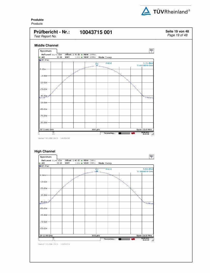
Table 8: Test result of Peak Output Power, 8DPSK modulation
Channel
Channel Frequency
Peak Output Power Limit
(MHz) (dBm) (W) (W)
Low Channel 2402 2.09 0.0016 0.125
Middle Channel 2441 4.71 0.0030 0.125
High Channel 2480 5.04 0.0032 0.125
Pmax: 3.2 mW

Produkte
Products
Prüfbericht - Nr.:
Test Report No. 10043715 001 Seite 17 von 48
Page 17 of 48
Test Plot of Peak Output Power, GFSK modulation
Low Channel
Middle Channel

Produkte
Products
Prüfbericht - Nr.:
Test Report No. 10043715 001 Seite 18 von 48
Page 18 of 48
High Channel
Test Plot of Peak Output Power, 8DPSK modulation
Low Channel
Produkte
Products
Prüfbericht - Nr.:
Test Report No. 10043715 001 Seite 19 von 48
Page 19 of 48
Middle Channel
High Channel
Produkte
Products
Prüfbericht - Nr.:
Test Report No. 10043715 001 Seite 20 von 48
Page 20 of 48
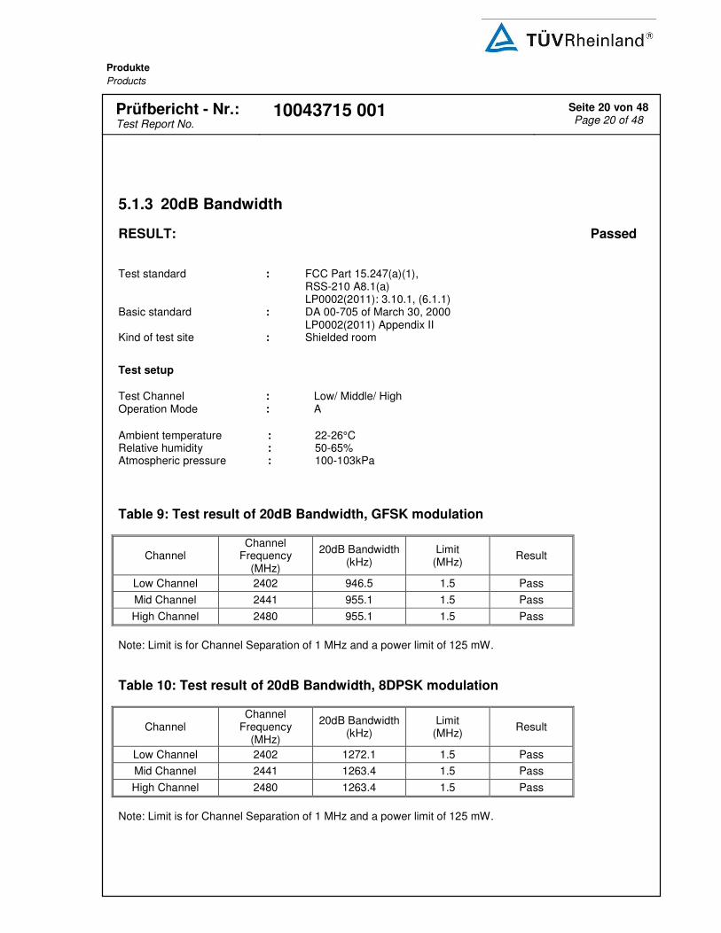
5.1.3 20dB Bandwidth
RESULT: Passed
Test standard : FCC Part 15.247(a)(1),
RSS-210 A8.1(a) LP0002(2011): 3.10.1, (6.1.1)
Basic standard : DA 00-705 of March 30, 2000 LP0002(2011) Appendix II
Kind of test site : Shielded room
Test setup
Test Channel : Low/ Middle/ High Operation Mode : A
Ambient temperature : 22-26°C Relative humidity : 50-65% Atmospheric pressure : 100-103kPa
Table 9: Test result of 20dB Bandwidth, GFSK modulation
Channel Channel
Frequency (MHz)
20dB Bandwidth (kHz)
Limit (MHz)
Result
Low Channel 2402 946.5 1.5 Pass
Mid Channel 2441 955.1 1.5 Pass
High Channel 2480 955.1 1.5 Pass
Note: Limit is for Channel Separation of 1 MHz and a power limit of 125 mW.
Table 10: Test result of 20dB Bandwidth, 8DPSK modulation
Channel Channel
Frequency (MHz)
20dB Bandwidth (kHz)
Limit (MHz)
Result
Low Channel 2402 1272.1 1.5 Pass
Mid Channel 2441 1263.4 1.5 Pass
High Channel 2480 1263.4 1.5 Pass
Note: Limit is for Channel Separation of 1 MHz and a power limit of 125 mW.

Produkte
Products
Prüfbericht - Nr.:
Test Report No. 10043715 001 Seite 21 von 48
Page 21 of 48
Test Plot of 20dB Bandwidth, GFSK modulation
Low Channel
Middle Channel

Produkte
Products
Prüfbericht - Nr.:
Test Report No. 10043715 001 Seite 22 von 48
Page 22 of 48
High Channel
Test Plot of 20dB Bandwidth, 8DPSK modulation
Low Channel

Produkte
Products
Prüfbericht - Nr.:
Test Report No. 10043715 001 Seite 23 von 48
Page 23 of 48
Middle Channel
High Channel

Produkte
Products
Prüfbericht - Nr.:
Test Report No. 10043715 001 Seite 24 von 48
Page 24 of 48
5.1.4 99% Bandwidth
RESULT: Passed
Test standard : RSS-Gen (Issue 3) Dec. 2010 Basic standard : RSS-Gen (Issue 3) Dec. 2010 Kind of test site : Shielded room
Test setup
Test Channel : Low/ Middle/ High Operation Mode : A
Ambient temperature : 22-26°C Relative humidity : 50-65% Atmospheric pressure : 100-103kPa
Table 11: Test result of 99% Bandwidth, GFSK modulation
Channel Channel
Frequency (MHz)
99% Bandwidth (kHz)
Limit (MHz)
Result
Low Channel 2402 876.9 / Pass
Mid Channel 2441 876.9 / Pass
High Channel 2480 876.9 / Pass
Table 12: Test result of 99% Bandwidth, PSK modulation
Channel Channel
Frequency (MHz)
99% Bandwidth (kHz)
Limit (MHz)
Result
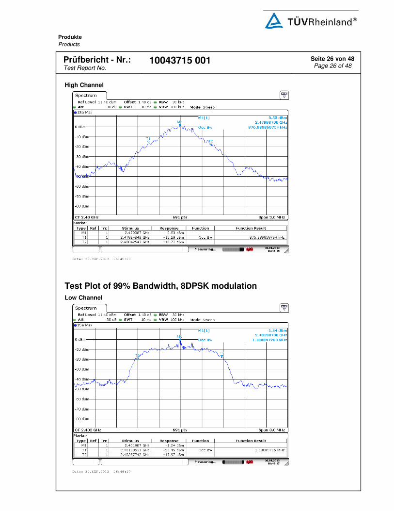
Low Channel 2402 1180.8 / Pass
Mid Channel 2441 1180.8 / Pass
High Channel 2480 1172.2 / Pass

Produkte
Products
Prüfbericht - Nr.:
Test Report No. 10043715 001 Seite 25 von 48
Page 25 of 48
Test Plot of 99% Bandwidth, GFSK modulation
Low Channel
Middle Channel
Produkte
Products
Prüfbericht - Nr.:
Test Report No. 10043715 001 Seite 26 von 48
Page 26 of 48
High Channel
Test Plot of 99% Bandwidth, 8DPSK modulation
Low Channel

Produkte
Products
Prüfbericht - Nr.:
Test Report No. 10043715 001 Seite 27 von 48
Page 27 of 48
Middle Channel
High Channel
Produkte
Products
Prüfbericht - Nr.:
Test Report No. 10043715 001 Seite 28 von 48
Page 28 of 48
5.1.5 Conducted spurious emissions and Frequency Band Edge measured in 100kHz Bandwidth
RESULT: Passed
Test standard : FCC part 15.247(d),
RSS-210 A8.5 LP0002(2011): 3.10.1, (5)
Basic standard : DA 00-705 of March 30, 2000 LP0002(2011) Appendix II
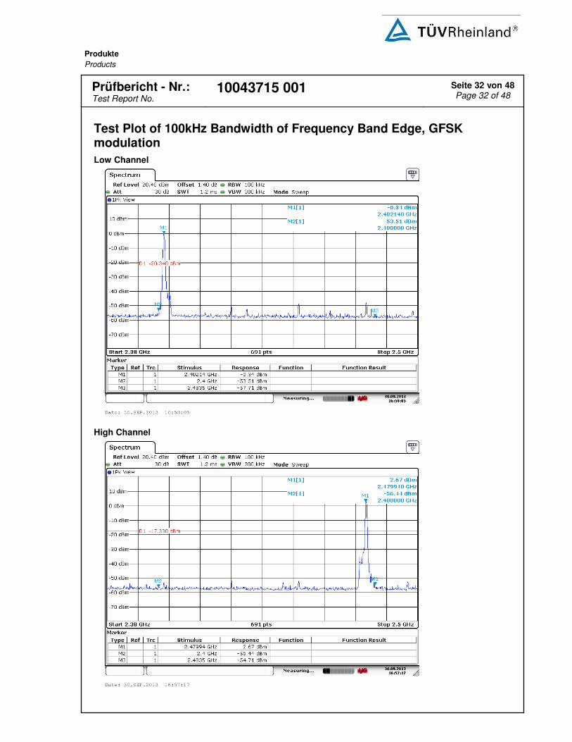
Limit : 20dB (below that in the 100kHz bandwidth within the band that contains the highest level of the desired power)
Kind of test site : Shielded room
Test setup
Test Channel : Low/ Middle/ High Operation Mode : A
Ambient temperature : 22-26°C Relative humidity : 50-65% Atmospheric pressure : 100-103 kPa
All emissions are more than 20dB below fundamental, details refer to following test plot, and compliance is achived as well. Due to the small size of the product and that there are no inductive components of significant size, 9kHz to 30MHz frequency range is not tested based on technical judgment.

Produkte
Products
Prüfbericht - Nr.:
Test Report No. 10043715 001 Seite 29 von 48
Page 29 of 48
Test Plot of 100kHz Conducted Emissions, GFSK modulation
Low Channel
Middle Channel

Produkte
Products
Prüfbericht - Nr.:
Test Report No. 10043715 001 Seite 30 von 48
Page 30 of 48
High Channel
Test Plot of 100kHz Conducted Emissions, 8DPSK modulation
Low Channel

Produkte
Products
Prüfbericht - Nr.:
Test Report No. 10043715 001 Seite 31 von 48
Page 31 of 48
Middle Channel
High Channel
Produkte
Products
Prüfbericht - Nr.:
Test Report No. 10043715 001 Seite 32 von 48
Page 32 of 48
Test Plot of 100kHz Bandwidth of Frequency Band Edge, GFSK modulation
Low Channel
High Channel

Produkte
Products
Prüfbericht - Nr.:
Test Report No. 10043715 001 Seite 33 von 48
Page 33 of 48
Test Plot of 100kHz Bandwidth of Frequency Band Edge, 8DPSK modulation
Low Channel
High Channel
Produkte
Products
Prüfbericht - Nr.:
Test Report No. 10043715 001 Seite 34 von 48
Page 34 of 48
5.1.6 Spurious Emission
RESULT: Passed
Test standard : FCC part 15.247(d), FCC 15.205, FCC 15.209, RSS-
210 2.2, RSS-210 A8.5 and RSS-Gen 7.2.1 LP0002(2011): 3.10.1, (5)
Basic standard : ANSI C63.10: 2009 Limits : Radiated emissions which fall in the restricted bands,
as defined in FCC 15.205(a) and RSS-210 2.7 (Table 1), must comply with the radiated emission limits specified in FCC 15.209(a) and RSS-210 2.7 (Table 2 and 3). Radiated emissions which fall in the restricted bands, as defined in LP0002(2011): 2.7 , must comply with the radiated emission limits specified in LP0002(2011): 2.8 Emission radiated outside the specified frequency bands must comply with the radiated emission limits specified in FCC 15.209(a) and FCC 15.249(a), RSS-210 2.7 (Table 2 and 3) and RSS-210 A2.9(a). Emission radiated outside the specified frequency bands must comply with the radiated emission limits specified in LP0002(2011): 2.8
Kind of test site : 3m Semi-Anechoic Chamber
Test setup
Test Channel : Low/ Middle/ High Operation Mode : A, B
Remark: Testing was carried out within frequency range 30MHz to the tenth harmonic. For details refer to Appendix 2. The Radiated Emissions testing was performed in the X, Y and Z axis orientation. The X Axis orientation is the worst-case and recorded in this test report. Due to the small size of the product and that there are no inductive components of significant size, 9kHz to 30MHz frequency range is not tested based on technical judgment.

Produkte
Products
Prüfbericht - Nr.:
Test Report No. 10043715 001 Seite 35 von 48
Page 35 of 48
5.1.7 Frequency Separation
RESULT: Passed
Test standard : FCC part 15.247(a)(1)
RSS-210 A8.1(b) LP0002(2011): 3.10.1, (6.1.1)
Basic standard : DA 00-705 of March 30, 2000 LP0002(2011) Appendix II
Limit : ≥ 25kHz or 2/3 of 20dB bandwidth, whichever is greater
Test setup
Test Channel : Low/ Middle/ High Operation Mode : A Ambient temperature : 24℃
Relative humidity : 53%
Table 13: Test result of Frequency Separation
Channel Channel Frequency
(MHz)
Measured Channel
Separation (MHz)
Limit (kHz)
Result
Record Channel 2441
1 ≥ 25kHz or 2/3 of 20dB bandwidth
Pass Record Channel adj 1 2440
Record Channel adj 2 2442

Produkte
Products
Prüfbericht - Nr.:
Test Report No. 10043715 001 Seite 36 von 48
Page 36 of 48
Test Plot of Frequency Separation
GFSK

Produkte
Products
Prüfbericht - Nr.:
Test Report No. 10043715 001 Seite 37 von 48
Page 37 of 48
5.1.8 Number of hopping frequency
RESULT: Passed
Test standard : FCC part 15.247(a)(1)(iii)
RSS-210 A8.1(d) LP0002(2011): 3.10.1, (6.1.2)
Basic standard : DA 00-705 of March 30, 2000 LP0002(2011) Appendix II
Limits : ≥ 15 non-overlapping channels Kind of test site : Shield room
Test setup
Test Channel : Low/ Middle/ High Operation Mode : A
Ambient temperature : 22-26°C Relative humidity : 50-65% Atmospheric pressure : 100-103 kPa
Table 14: Test result of Number of hopping frequency
Frequency Range Measured Quantity of Hopping
Channel Limit Result
2400 to 2483.5 MHz 79 ≥15 Pass

Produkte
Products
Prüfbericht - Nr.:
Test Report No. 10043715 001 Seite 38 von 48
Page 38 of 48
Test Plot of Number of hopping frequencies

Produkte
Products
Prüfbericht - Nr.:
Test Report No. 10043715 001 Seite 39 von 48
Page 39 of 48
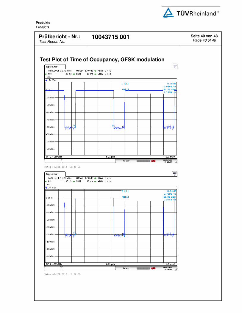
5.1.9 Time of Occupancy
RESULT: Passed
Test standard : FCC part 15.247(a)(1)(iii)
RSS-210 A8.1(d) LP0002(2011): 3.10.1, (6.1.2)
Basic standard : DA 00-705 of March 30, 2000 LP0002(2011) Appendix II
Limits : 0.4s Kind of test site : Shield room
Test setup
Test Channel : Low/ Middle/ High Operation Mode : A
Ambient temperature : 22-26°C Relative humidity : 50-65% Atmospheric pressure : 100-103 kPa
Table 15: Test result of Time of Occupancy
Data Mode Captured
Burst (s)
Dwell time (s)
On+Off time (s)
Limit (s)
Result
DH5 0.0030 0.3151 0.003754 0.4 Pass
3DH5 0.0025 0.2626 0.003754 0.4 Pass
Note: Dwell time = Pulse width x (Hopping rate / Number of channels) x Period
Period = 0.4 (seconds/ channel) x 79 (channel) = 31.6 seconds.
Produkte
Products
Prüfbericht - Nr.:
Test Report No. 10043715 001 Seite 40 von 48
Page 40 of 48
Test Plot of Time of Occupancy, GFSK modulation

Produkte
Products
Prüfbericht - Nr.:
Test Report No. 10043715 001 Seite 41 von 48
Page 41 of 48
Test Plot of Time of Occupancy, 8DPSK modulation

Produkte
Products
Prüfbericht - Nr.:
Test Report No. 10043715 001 Seite 42 von 48
Page 42 of 48
5.2 Mains Emissions
5.2.1 Mains Conducted Emissions
RESULT: Passed
Test standard : FCC Part 15.207
FCC Part 15.107 LP0002(2011): 2.3
Limits : Mains Conducted emissions as defined in above standards
Kind of test site : Shielded Room
Test setup
Test Channel : Middle Operation mode : A
Remark: For details refer to Appendix D.

Produkte
Products
Prüfbericht - Nr.:
Test Report No. 10043715 001 Seite 43 von 48
Page 43 of 48
6. Safety Human exposure
6.1 Radio Frequency Exposure Compliance
6.1.1 Electromagnetic Fields
RESULT: Passed
Test standard : FCC KDB Publication 447498 Since maximum peak output power of the transmitter is <10mW, hence the EUT is exclueded from SAR evaluation according to FCC KDB publication 447498 D01: Mobile Portable RF Exposure. The enclosure provides a separation distance of > 5mm to the antenna system.

Produkte
Products
Prüfbericht - Nr.:
Test Report No. 10043715 001 Seite 44 von 48
Page 44 of 48
7. Photographs of the Test Set-Up Photograph 1: Set-up for Spurious Emissions (Front View)
Produkte
Products
Prüfbericht - Nr.:
Test Report No. 10043715 001 Seite 45 von 48
Page 45 of 48
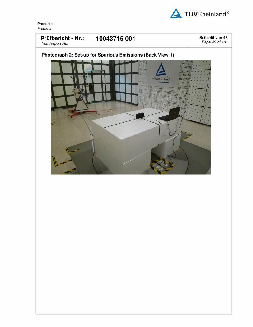
Photograph 2: Set-up for Spurious Emissions (Back View 1)

Produkte
Products
Prüfbericht - Nr.:
Test Report No. 10043715 001 Seite 46 von 48
Page 46 of 48
Photograph 3: Set-up for Spurious Emissions (Back View 2)
Photograph 4: Set-up for Conducted testing

Produkte
Products
Prüfbericht - Nr.:
Test Report No. 10043715 001 Seite 47 von 48
Page 47 of 48
Photograph 5: Set-up for for Mains Conducted testing Back
Photograph 6: Set-up for for Mains Conducted testing Front

Produkte
Products
Prüfbericht - Nr.:
Test Report No. 10043715 001 Seite 48 von 48
Page 48 of 48
8. List of Tables
Table 1: Applied Standard and Test Levels .................................................................................................. 5
Table 2: List of Test and Measurement Equipment ...................................................................................... 7
Table 3: Emission Measurement Uncertainty................................................................................................ 8
Table 4: Technical Specification of EUT ....................................................................................................... 9
Table 5: Frequency hopping information ..................................................................................................... 10
Table 6: Test result of Peak Output Power, GFSK modulation ................................................................... 16
Table 7: Test result of Peak Output Power, 8DPSK modulation ................................................................. 16
Table 8: Test result of 20dB Bandwidth, GFSK modulation ........................................................................ 20
Table 9: Test result of 20dB Bandwidth, 8DPSK modulation ...................................................................... 20
Table 10: Test result of 99% Bandwidth, GFSK modulation ....................................................................... 24
Table 11: Test result of 99% Bandwidth, PSK modulation .......................................................................... 24
Table 12: Test result of Frequency Separation ........................................................................................... 35
Table 13: Test result of Number of hopping frequency ............................................................................... 37
Table 14: Test result of Time of Occupancy ................................................................................................ 39
9. List of Photographs
Photograph 1: Set-up for Spurious Emissions (Front View) ........................................................................ 44
Photograph 2: Set-up for Spurious Emissions (Back View 1) ..................................................................... 45
Photograph 3: Set-up for Spurious Emissions (Back View 2) ..................................................................... 46
Photograph 4: Set-up for Conducted testing ............................................................................................... 46
Photograph 5: Set-up for for Mains Conducted testing Back ...................................................................... 47
Photograph 6: Set-up for for Mains Conducted testing Front ...................................................................... 47