Embed Size (px)
Citation preview

PUBLIC
NXP, THE NXP LOGO AND NXP SECURE CONNECTIONS FOR A SMARTER WORLD ARE TRADEMARKS OF NXP B.V.
ALL OTHER PRODUCT OR SERVICE NAMES ARE THE PROPERTY OF THEIR RES PECTIVE OWNERS. © 2021 NXP B.V.
2 0 2 1年 9月
邓平飞恩智浦应用工程师
100~1400瓦全数字设定PFC +
LLC整合型电源控制IC:
TEA2017

1PUBLIC
AGENDA
Marketing Session
• The developing story of TEA1916, 2016 to 2017
• Key unique features of TEA2017 & key performance; also using our 600W demo board as examples.
• Energy saving regulation
• Use cases TEA2017
• NXP LLC Product Portfolio
• Web address of related documents of TEA2017 on NXP web.
Technical Application Session
• Power Factor and THD Improvement
• Mixed Mode PFC: “CCM”+ “QR”+ “DCM with valley detection”
• PFC frequency decrement
• PFC frequency jitter
• PFC improved soft-start
• MTP setting & Programming
• Introduction to TEA2017 600W demo boad
Q&A

2PUBLIC
TEA2017
NEW GENERATION
DIGITAL & PROGRAMMABLE
RESONANT POWER PLATFORM
80” TV or
65” OLED TV
12V/33A 300W
600W
300~400W
10~20 USB Ports
Charger
Industrial
Power
Regular:300W
Peak Power:500WIndoor
Display
Power
5V/40A~80A

3PUBLIC
LLC & PFC in single
SO16 package
MTP settings internal
NEXT GENERATION: DIGITAL PROGRAMMABLE PFC + LLC:
TEA2017
• DCM/QR/CCM Mixed Mode PFC
• Up to 1,400W
• Power Factor, THD and EMI improvement
• High amount of protections, including second independent OVP & inrush current
• High configurability via MTP
• Digital state-machine. NO FIRMWARE !!
➔
TEA1716
TEA19162
TEA19161
➔
Year 2012
First to meet
EUP Lot 6Year 2016
Digital Cycle—by-Cycle
MTP setting by 4
registers
Year 2019
Programmability /
Flexibility single
package
TEA2016
Year 2021
TEA2016 +
Mixed Mode
DCM/BCM/CCM PFC
TEA2017
Pin compatible with
TEA2016
SO16 package

4PUBLIC
Additional Advantages of TEA2017
• Very high efficacy a light load
• Very low component count
• Fast Dynamic load response (<+- 5V when the load increased from 0% to 100% )
• Very low power consumption @no load(<70mW @ no load for 300W/20V)
• Accurate burst‐mode level
• Low audible noise
• Many protections
• Short development time needed
• Mature platform (very high volume of TEA2016 & TEA1916 in Market)
Pin compatible
with TEA2016
S1
S2
Vout (DC)D2
D1
CR
LM
LS
SUPIC
SNSFB
GND
GATELS
GATEHS
SUPHS
HB
SNSCURLLC
SNSCAP
SNSBOOST
TEA2017
CSUPHS
CSUPIC
SNSMAINS
GATEPFC
SNSCURPFC
SUPHV
GATELS
Vboost
RSNSCUR
Mains-L
Mains-N
RSENSE
RSETTING

5PUBLIC
Test Results for 600W Demo (185mmx 73.5mm x 39mm; 18.5W/In 3) with
TEA2017AAT, TEA2209T & TEA2095T

6PUBLIC
能源法规与市场趋势

7PUBLIC
能源法规——刚刚发布或即将发布
⚫加州新能源法规: >80% 从~3W到以上(何时?)
⚫电视电源: <0.3W@待机模式(e.g. 12V/10mA) (某些品牌目前标准)
⚫EPA能源之星 7.0
✓希望将最低计算 IPS 效率从 80Plus Bronze 提高到 80Plus Silver 效率等級 (自2019年11月生效)
✓完整网络连接能力- 已经修改完整网络连接能力的定义,以适应业界正在开发的全新极低功率模式。这些新模式可让网络持续处于连线状态,但功耗低于2瓦。
⚫EUP/ERP Lot 7: <0.2W@待机模式/无负载(何时?)
⚫ UL62368 (2019上半年)
⚫…

8PUBLIC
大尺寸电视机电源的改变 (55/65 & OLED)
• 總功率大增• 輸出電壓變小• 同步整流使用機率
大增 (TEA2095T)
不再使用 Flyback
(反激), 改用PFC+LLC(諧振)
尺寸 W/O Type Port &
Edge LEDs
W/O Type C port &
Direct Bakclight
With 2 Type C Ports
& Direct Backlight
2 Type C ports &
OLED Light Source
55” Vout <=24V: 50W
Vout >50V: 80W
Sub-TTL: 130W
Vout <=24V: 50W
Vout > 50V: 100W
Sub-TTL: 150W
Vout <24V: 150W
Vout >50V: 100W
Sub-TTL: 250W
Vout <24V 150W
Vout 30~48V: 250W
Sub-TTL: 400W
65” Vout <=24V: 50W
Vout >50V: 120W
Sub-TTL: 170W
Vout <=24V: 50W
Vout > 50V: 150W
Sub-TTL: 250W
Vout <24V: 150W
Vout >50V: 150W
Sub-TTL: 300W
Vout <24V 150W
Vout 30~48V: 350W
Sub-TTL: 500W

9PUBLIC
PC电源的主要市场趋势(桌面)多输出→单输出
2018 2019 2020 2021 2022 2013
200W
300W
• Single output (+12)• Higher Power Density• Higher power for Graphy• Longer time peak Power• Low Energy Consumption
Single output
Desk top Multi outputs 350W
(12V, 5V, 3.3V)
Single Peak output: 12V/500W
PFC LLCMAINS
TEA19161
SR
TEA2095
Pout:+12V or
+20V
CTRL
Standby Power
Pout:+5Vstandby
DCDC
TEA2017
400W
600W
500W

1 0PUBLIC
多输出电视趋势➔ 2个输出,例如 >=300W LED with Type Ports or
OLED 电视电源
CTRL
Standby PowerR
ectifie
r
500W
400W
30W
Output: +24V,12V &
5V/250W
2018 2019 2020 2021 2022 2023
PFC LLCPout 1A:+12V (Audio)
Pout1 C:+5Vstandby
LDO or
DCDC
Pout 1B: +24V (feedback for CC ckt)
TEA2017

PUBLIC
为什么AIO和台式电脑为单输出功率
• 设计更简单;
• 更容易通过法規要求;
• 减少组件数量;
• 更坚固/可靠,更长的产品寿命;
• 更容易获得EnergyStar法规认证;
• LDO或DC / DC级的效率更高,成本更低。

1 2PUBLIC
TEA2017 成功应用案例

1 3PUBLIC
End Product: TV SET
Customer TV Power Maker
BL-SIP Part No.
(Sockets)TEA2017AAT
End Application >70” TV Set platform
Why TEA2017 chosen
• Easier to use & debug than the
other combo IC
• PCB size smaller & less
compony count than old
projects
• Better Power saving
Use Experience
• Direct support from NXP FAE at
begging stage
• Disti FAE support from PCB
layout to debug
TEA2017AAT
Flyback Controller Rectification
USE CASE: 400~600W TV POWER

1 4PUBLIC
Customer Out Door Display Makers
BL AA Device TEA2017AAT+ TEA2095
End ApplicationChina local brands outdoor display
Power with 5Vout
Why TEA2017AAT
Chosen
Product features highly match customer
requirements
Good relationship with customer
High Efficiency at light and high load
Low component count
Use Experience
• Direct support from NXP FAE at begging
stage
• Disti FAE support from PCB layout to
debug
• Short development time
USE CASE: 300W OUTDOOR DISPLAY POWER
Outdoor Display Power
TE
A2
01
7A
AT
TEA2
09
5

1 5PUBLIC
Customer USB Multi Port charger makers
BL AA Device TEA2017AAT+ TEA2095
End Application More than-10-Ports USB Chargers
Why TEA2017AAT
Chosen
• Low power consumption at no load,
tiny load & standby Power
• Very low component count
• Mature & high share in the market
Use Experience
• Direct support from NXP FAE at begging
stage
• Disti FAE support from PCB layout to
debug
• Short development time
USE CASE: 300W MULTI-PORT USB PD CHARGER
Multi-port USB Charger
S1
S2
Vout (DC)D2
D1
CR
LM
LS
SUPIC
SNSFB
GND
GATELS
GATEHS
SUPHS
HB
SNSCURLLC
SNSCAP
SNSBOOST
TEA2017
CSUPHS
CSUPIC
SNSMAINS
GATEPFC
SNSCURPFC
SUPHV
GATELS
Vboost
RSNSCUR
Mains-L
Mains-N
RSENSE
RSETTING
DC
/DC
Co
nve
rte
r
Mo
du
le

1 6PUBLIC
TEA2016
Customer PC Power Maker
BL AA Device TEA2017AAT+ TEA2095ET
ApplicationDesktop PC Power with 2- time peak
power
Why TEA2017AAT
Chosen
• Low power consumption at no load,
tiny load & standby Power
• Easy to pass Energy Star
• Meet 2 time-peak power requirement
• Very low component count
• Mature & high share in the market
Use Experience
• Direct support from NXP FAE at
begging stage
• Disti FAE support from PCB layout
to debug
• Short development time
USE Case: 500W Peak Power for Desktop PC
PC Power
TEA2095
TE
A2
01
7A
AT

1 7PUBLIC
最新恩智浦电源IC产品组合

1 8PUBLIC
Application Description Part Number USP Status & Remarks
>75W Adapters, Lighting but
no THD requirement, NB PC,
Desktop PC, AIO PC, TV,
out/in door display. Medical
Power, Multi-Port USB
Charger & etc. (<=300W)
LLC digital controller+
DCM PFC Controller
TEA19161 (SO16)+ TEA19162 (SO8) • Parameters can be set by 4 registers
• <70mW@no load for 240W/12V
• 2~15% higher at load <10%;
• <+/-5% voltage regulation for 0% to 100% load
• Meets Platinum standard
TEA19161+TEA19162:
MP Q1’16
Design tool of TEA1916
released April’20
SR IC for LLC power supply
(<1000W)
LLC Synchronous
Rectifier IC
TEA1995T (SO8) or TEA2095T(SO8)
/TEA2095TE(HSO8)
• 2~7% High efficiency at middle load via adaptive driving
capability by loading
• TEA2095 for higher power (over 300W) & lower Vds
MOSFET
TEA1995: MP Q3’15
TEA2095: Released Nov’19
TEA2095T(E)/1 with copper
wire: released Q3’20
>75W Adapters, Lighting but
no THD requirement, NB PC,
Desktop PC, AIO PC, TV,
out/in door display. Medical
Power, Multi-Port USB
Charger with GAN Transistor &
etc. (<=300W)
Combo Controller with
LLC digital control+
DCM PFC Control
TEA2016 (SO16) + (TEA1995 or
TEA2095)
• Parameters can be set for >80 parameters
• 30~50 components reduced vs TEA1916 generation
• Meets Platinum standard
• Advantage of TEA19161+ TEA19162
TEA2016 released June’19
200~ few KWs for any power
which needs higher efficiency
on Bridge stage
Active Bridge Rectifier
Controller can work
under any
topology(e.g. LLC, &
Forward, Fullbridge &
etc.)
TEA2208 (SO14): replace 4 diodes
TEA2206 (SO8) : replace 2 Diodes
TEA2209 (SO16): replace 4 Diodes,
much lower power @no/tiny load
• Forward conduction losses of the diode rectifier
bridge are eliminated
• Very low IC power consumption (2 mW) with X-
capacitor discharge
• Very low external part count
TEA2208: released Nov’19
TEA2206: Released Dec’20
TEA2209: Released Jan’21
Up to 1,400W: Adapters,
Lighting , NB PC, Desktop PC,
AIO PC, TV, out/in door
display. Medical Power, Multi-
Port USB Charger with GAN
Transistor & etc.
Combo Controller with
LLC digital control+
DCM/QR/CCM Mixed
Mode PFC
TEA2017 (SO16) + (TEA2095) • Advantages of TEA2016
• Low THD, high PF value & easier to handle EMI
• DCM/QR/CCM Mixed Mode PFC
TEA2017: released June’21
Design tool of TEA2017:
Released July’21
LLC拓扑的推力产品ACDC电源控制器

1 9PUBLIC
TEA2017官方网站
• https://www.nxp.com.cn/products/power-management/ac-dc-solutions/ac-dc-
controllers-with-integrated-pfc/digital-configurable-llc-and-multimode-pfc-
controller:TEA2017AAT

2 0PUBLIC2 0
PUBLIC
NXP, THE NXP LOGO AND NXP SECURE CONNECTIONS FOR A SMARTER WORLD ARE TRADEMARKS OF NXP B.V.
ALL OTHER PRODUCT OR SERVICE NAMES ARE THE PROPERTY OF THEIR RES PECTIVE OWNERS. © 2021 NXP B.V.
TEA2017 : Digital configurable
LLC and multimode PFC
controller promotion

2 1PUBLIC
TEA2017 Application schematic
PFC part
LLC part✓ CCM PFC + LLC combo controller with SO16
✓ Digital control with MTP ; very less BOM counts

2 2PUBLIC
Contents
• Power Factor and THD improvement
• Mixed mode PFC ; “CCM” + “QR” + “DCM with valley detection”
• PFC frequency decrement
• PFC frequency jitter
• PFC improved soft-start
• MTP setting and programming
• Introduction to TEA2017 600W demo board
2 3PUBLIC
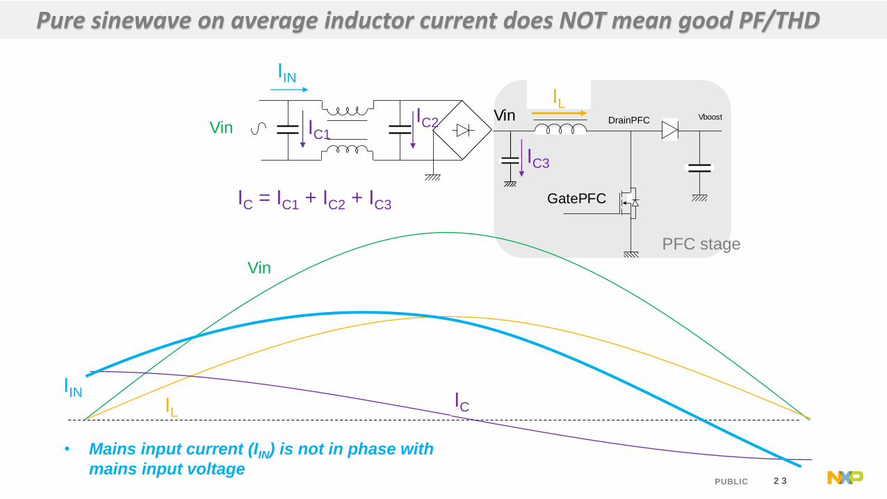
Vboost
IL
GatePFC
DrainPFCVin
IIN
IC3
VinIC2IC1
IC = IC1 + IC2 + IC3
Pure sinewave on average inductor current does NOT mean good PF/THD
IL
Vin
IINIC
IL
• Mains input current (IIN) is not in phase with
mains input voltage
PFC stage

2 4PUBLIC
How to achieve better PF and THD ?
IL
Vin
IIN IC
Vboost
IL
GatePFC
DrainPFCVin
IIN
IC3
VinIC2IC1
IC = IC1 + IC2 + IC3
• Negative current (sourcing current from PFC to input) in
shifted phase is not possible to be implemented. Shifted phase
• Therefore, no switching operation during shifted phase.
IL
PFC stage

2 5PUBLIC
• Power factor > 0.99, iTHD < 10% at 100% load
• Power factor > 0.88, iTHD < 20% at 20% load
0.86
0.88
0.9
0.92
0.94
0.96
0.98
1
20% 30% 40% 50% 60% 70% 80% 90% 100%
Po
wer
fac
tor
Output power
90Vac/60Hz
115Vac/60Hz
230Vac/50Hz
264Vac/50Hz
0.000
2.000
4.000
6.000
8.000
10.000
12.000
14.000
16.000
18.000
20.000
20 30 40 50 60 70 80 90 100
iTH
D[%
]
Output power [%’
90Vac/60Hz
115Vac/60Hz
230Vac/50Hz
264Vac/50Hz
Power factor and THD test result

2 6PUBLIC
Contents
• Power Factor and THD improvement
• Mixed mode PFC ; “CCM” + “QR” + “DCM with valley detection”
• PFC frequency decrement
• PFC frequency jitter
• PFC improved soft-start
• MTP setting and programming
• Introduction to TEA2017 600W demo board

2 7PUBLIC
TEA2017 _ Mixed mode PFC control ; CCM/DCM/QR
Power
QR
Fmin
Fmax
DCM CCM
✓ Typical design for high power application
✓ Even though frequency control intends to increase frequency at higher power range, the practical
frequency is decreased for QR operation.

2 8PUBLIC
Contents
• Power Factor and THD improvement
• Mixed mode PFC ; “CCM” + “QR” + “DCM with valley detection”
• PFC frequency decrement
• PFC frequency jitter
• PFC improved soft-start
• MTP setting and programming
• Introduction to TEA2017 600W demo board

2 9PUBLIC
TEA2017 _ Frequency by output power
Idesired
Frequency
ia
ib
Output power
Phase factor
w/o switching
Vmains
Phase starting
frequency increase
Increasing
frequencyDecreasing
frequencyDecreasing
frequency

3 0PUBLIC
Contents
• Power Factor and THD improvement
• Mixed mode PFC ; “CCM” + “QR” + “DCM with valley detection”
• PFC frequency decrement
• PFC frequency jitter
• PFC improved soft-start
• MTP setting and programming
• Introduction to TEA2017 600W demo board

3 1PUBLIC
TEA2017 _ PFC jitter function
Jitter frequency change amplitude
- Average frequency w/ jitter is same as frequency control value.
Frequency control curve w/o jitter
Frequency control curve w/ jitter
VPFCinput
FPFC
Without Jitter With Jitter
Frequency control curve w/o jitter
Frequency control curve w/ jitter

3 2PUBLIC
Contents
• Power Factor and THD improvement
• Mixed mode PFC ; “CCM” + “QR” + “DCM with valley detection”
• PFC frequency decrement
• PFC frequency jitter
• PFC improved soft-start
• MTP setting and programming
• Introduction to TEA2017 600W demo board

3 3PUBLIC
startupMains
connection
PFC Vout
Vreg
time
overshoot
Internal regulation parameter
(such as PFCCOMP of TEA19162)
PFC Vref
2.5V
PFC switching start
Slow control loop makes OVP here.
TEA2016 _ start-up

3 4PUBLIC
timestartupMains
connection
PFC Vout
timestartupMains
connection
PFC Vref
2.5V
PFC switching start
SNSBOOST pin detected mains peak level here.
Internal Vref is gradually increased to reduce
overshoot during start-up
TEA2017 _ start-up

3 5PUBLIC
Contents
• Power Factor and THD improvement
• Mixed mode PFC ; “CCM” + “QR” + “DCM with valley detection”
• PFC frequency decrement
• PFC frequency jitter
• PFC improved soft-start
• MTP setting and programming
• Introduction to TEA2017 600W demo board

3 6PUBLIC
TEA2017 _ MTP setting and programming
3 7PUBLIC
Contents
• Power Factor and THD improvement
• Mixed mode PFC ; “CCM” + “QR” + “DCM with valley detection”
• PFC frequency decrement
• PFC frequency jitter
• PFC improved soft-start
• MTP setting and programming
• Introduction to TEA2017 600W demo board

3 8PUBLIC
Discrete Lr
Top side Bottom side
LLC
transformer
LLC resonant
capacitor
PFC output
capacitorPFC MOSFET PFC diode
PFC
inductor
Active bridge
daughter board TEA2017AAT
TEA2095TE
SR MOSFET *8
Inrush diodePFC current
sense resistor
LLC MOSFET
Demo board photo

3 9PUBLIC
90Vac & 12V/50A 264Vac & 12V/50A
Waveform
CH1 : Ipfc_inductor
CH2 : DrainPFC
CH3 : GatePFC
F2 : PFC frequency
• PFC phase shift operates well for good power factor
• PFC frequency is min value nearby zero-crossing. As Ipfc_inductor average is increased, frequency is increased to max
value.
• After PFC frequency increased to max value, frequency jitter operates for better EMI
Frequency Jitter Frequency Jitter
Phase shift Phase shift
Fmin
Fmax
Fmin
Fmax
PFC normal operation

4 0PUBLIC
❑ Efficiency achievement key points
• At heavy load condition
• Active bridge
• PFC frequency control
• SR performance
• At light load condition
• PFC frequency control
• PFC valley detection
• LLC Low power mode operation
• Test condition : without 2W Fan
0.9
0.92
0.89
0.92
0.94
0.9
0.9221
0.9464 0.9435
0.9325
0.9535 0.9544
0.86
0.87
0.88
0.89
0.9
0.91
0.92
0.93
0.94
0.95
0.96
20% 30% 40% 50% 60% 70% 80% 90% 100%
Effi
cien
cy
Output load
Platinum spec at 115Vac Platinum spec at 230Vac
Efficiency result at 115Vac Efficiency result at 230Vac
Efficiency test result

4 1PUBLIC
Input power test result,
115Vac
Input power test result,
230VacOutput load condition Specification
0.082 W 0.110 W No load 0.15 W
0.263 W 0.277 W 0.0125 A 0.5 W
1.628 W 1.579 W 0.104 A 2 W
3.807 W 3.671 W 0.25 A 4 W
6.226 W 6.017 W 0.417 A 6.25 W
Test equipment ; WT210 with 300s integration time
Additional power loss breakdown at no load condition 1. Compact TEA2017 design (e.g. TEA2017 240W demo) : 70 mW
2. Active bridge : 8 mW
3. 1uF input capacitor: 15 mW
4. LDO and others : 7 mW
Standby power consumption
4 2PUBLIC
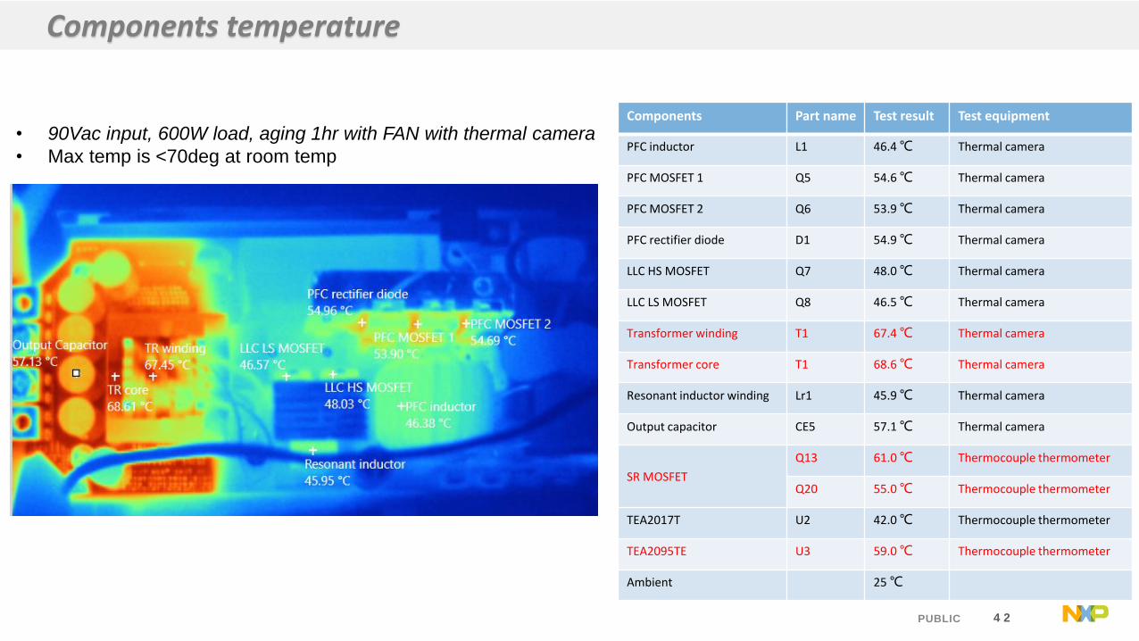
• 90Vac input, 600W load, aging 1hr with FAN with thermal camera
• Max temp is <70deg at room temp
Components Part name Test result Test equipment
PFC inductor L1 46.4 ℃ Thermal camera
PFC MOSFET 1 Q5 54.6 ℃ Thermal camera
PFC MOSFET 2 Q6 53.9 ℃ Thermal camera
PFC rectifier diode D1 54.9 ℃ Thermal camera
LLC HS MOSFET Q7 48.0 ℃ Thermal camera
LLC LS MOSFET Q8 46.5 ℃ Thermal camera
Transformer winding T1 67.4 ℃ Thermal camera
Transformer core T1 68.6 ℃ Thermal camera
Resonant inductor winding Lr1 45.9 ℃ Thermal camera
Output capacitor CE5 57.1 ℃ Thermal camera
SR MOSFET
Q13 61.0 ℃ Thermocouple thermometer
Q20 55.0 ℃ Thermocouple thermometer
TEA2017T U2 42.0 ℃ Thermocouple thermometer
TEA2095TE U3 59.0 ℃ Thermocouple thermometer
Ambient 25 ℃
Components temperature

4 3PUBLIC

![基于 ESP8266 的远程控制插座设计 - paper.edu.cn · 者对国外家居产品的认可度更高一点[4]。 1 总体方案设计 1.1 系统总体方案的确定 基于ESP8266](https://img.pdfslide.us/doc/110x75/5e60359e43785e5dff24fe0d/-esp8266-ceoecee-papereducn-eceec4.jpg)


![mono bazar - 瓦町FLAGmono bazar [食料品・生活雑貨] 〈 期間限定 〉 Title 瓦町FLAG 2階 Created Date 9/24/2020 3:30:09 PM](https://img.pdfslide.us/doc/110x75/6025b34a3fea680ece451be6/mono-bazar-ccflag-mono-bazar-efcee-oeee-.jpg)