Embed Size (px)
Citation preview
IEEE 100BASE-T1 EMC Test Specification for
Common Mode Chokes Version 1.0
Author & Company Dr. Bernd Körber, FTZ Zwickau
Title 100BASE-T1 EMC Test Specification for Common Mode Chokes
Version 1.0
Date October 4, 2017
Status Final
Restriction Level Public
This measurement specification shall be used as a standardized common scale for EMC evaluation of common mode chokes for 100BASE-T1 in automotive applications.

OPEN Alliance
Restriction Level: public | 1000BASE-T1 EMC Test Specification for Common Mode Chokes | Oct-17 2
Version Control of Document
Version Author Description Date
0.1 B. Körber Initial document 05/26/16
0.2 B. Körber Editorial changes
Reference to EMC test specification for transceiver deleted
Measurement network for single ended S-Parameter measurements changed (75 Ω to 124 Ω)
Test procedure and damage evaluation criteria for ESD tests changed
Example for ESD test board added
Formula expression added for recommended limits
Proposal for change of S-Parameter limits added
Section TDR tests shifted to informative Appendix
08/03/17
1.0 B. Körber Shift to final version 10/04/17
Restriction level history of Document
Version Restriction Level Description Date
0.1 Open internal only 05/26/16
0.2 Open internal only 08/03/17
1.0 Public 10/04/17

OPEN Alliance
Restriction Level: public | 1000BASE-T1 EMC Test Specification for Common Mode Chokes | Oct-17 3
Copyright Notice and Disclaimer
OPEN Alliance members whose contributions were incorporated in the OPEN Specification (the “Contributing Members”) own the copyrights in the OPEN Specification, and permit the use of this OPEN Specification, including the copying and distribution of unmodified copies thereof, for informational purposes only. Such permission relates only to the OPEN Specification and does not include a specification published elsewhere and referred to in the OPEN Specification.
The receipt of an OPEN Specification shall not operate as an assignment or license under any patent, industrial design, trademark, or other rights as may subsist in or be contained in or reproduced in any OPEN Specification, and the implementation of this OPEN Specification will require such a license.
THIS OPEN SPECIFICATION IS PROVIDED ON AN “AS IS” BASIS AND ALL WARRANTIES, EITHER EXPLICIT OR IMPLIED, ARE EXCLUDED UNLESS MANDATORY UNDER LAW. ACCORDINGLY, THE OPEN ALLIANCE AND THE CONTRIBUTING MEMBERS MAKE NO REPRESENTATIONS OR WARRANTIES WITH REGARD TO THE OPEN SPECIFICATION OR THE INFORMATION (INCLUDING ANY SOFTWARE) CONTAINED THEREIN, INCLUDING ANY WARRANTIES OF MERCHANTABILITY, FITNESS FOR PURPOSE, OR ABSENCE OF THIRD PARTY RIGHTS AND MAKE NO REPRESENTATIONS AS TO THE ACCURACY OR COMPLETENESS OF THE OPEN SPECIFICATION OR ANY INFORMATION CONTAINED THEREIN.
THE OPEN ALLIANCE AND CONTRIBUTING MEMBERS ARE NOT LIABLE FOR ANY LOSSES, COSTS, EXPENSES OR DAMAGES ARISING IN ANY WAY OUT OF USE OR RELIANCE UPON THE OPEN SPECIFICATION OR ANY INFORMATION THEREIN. NOTHING IN THIS DOCUMENT OPERATES TO LIMIT OR EXCLUDE ANY LIABILITY FOR FRAUD OR ANY OTHER LIABILITY WHICH IS NOT PERMITTED TO BE EXCLUDED OR LIMITED BY OPERATION OF LAW.
Without prejudice to the foregoing, the OPEN Specification was developed for automotive applications only. The OPEN Specification has neither been developed, nor tested for non-automotive applications.
OPEN Alliance reserves the right to withdraw, modify, or replace the OPEN Specification at any time, without notice.

OPEN Alliance
Restriction Level: public | 1000BASE-T1 EMC Test Specification for Common Mode Chokes | Oct-17 4
Contents 1 Introduction .......................................................................................................................................... 5
1.1 Scope ............................................................................................................................................. 5
1.2 References .................................................................................................................................... 5
1.3 List of abbreviations and definitions ............................................................................................. 6
2 Required Tests ...................................................................................................................................... 7
2.1 General .......................................................................................................................................... 7
2.2 Mixed mode S-Parameter measurement ..................................................................................... 8
2.2.1 Test setup .............................................................................................................................. 8
2.2.2 Test procedure and parameters ........................................................................................... 9
2.3 Damage from ESD ....................................................................................................................... 11
2.3.1 Test setup ............................................................................................................................ 11
2.3.2 Test procedure and parameters ......................................................................................... 12
2.4 Test of saturation effect at RF immunity tests ........................................................................... 14
2.4.1 Test setup ............................................................................................................................ 14
2.4.2 Test procedure and parameters ......................................................................................... 15
Appendix A - Test fixtures ........................................................................................................................... 17
A.1 General requirements for test fixtures ....................................................................................... 17
A.2 Self-balance requirements for S-Parameter test fixture ............................................................ 17
A.3 Example for test fixture S-Parameter measurement .................................................................. 19
A.4 Example for test fixture ESD tests ............................................................................................... 20
Appendix B – Recommended limits for tests .............................................................................................. 21
B.1 S-Parameter measurements ....................................................................................................... 21
B.2 Damage from ESD ....................................................................................................................... 24
B.3 Test of saturation effect at RF immunity tests ........................................................................... 24
Appendix C – TDR measurement of differential mode impedance (informative) ...................................... 25
C.1 Test setup .................................................................................................................................... 25
C.2 Test procedure and parameters ................................................................................................. 26

OPEN Alliance
Restriction Level: public | 1000BASE-T1 EMC Test Specification for Common Mode Chokes | Oct-17 5
1 Introduction
1.1 Scope
This measurement specification shall be used as a standardized common scale for EMC evaluation of
common mode chokes (CMCs) intended to use with 100BASE-T1 in automotive applications according to
[IEEE1]. It contains recommended limits. The final judgment of the tested device is left to the customer.
This specification is not applicable for devices that are intended for use in Power over Data Line
applications.
This instruction includes test procedures and test setups concerning:
Mixed mode S-Parameter measurement
Test of damage from ESD
Test of saturation effect at RF immunity tests.
For optional TDR measurement of differential mode impedance procedures and test setup are given in an
informative appendix.
1.2 References
[IEEE1] IEEE Std. 802.3bw
[IEC1] IEC 61000-4-2, Electromagnetic compatibility, Part 4-2: Testing and measurement techniques – Electrostatic discharge immunity test

OPEN Alliance
Restriction Level: public | 1000BASE-T1 EMC Test Specification for Common Mode Chokes | Oct-17 6
1.3 List of abbreviations and definitions
CDMR Common to Differential Mode Rejection, common mode single ended measured
CMC Common Mode Choke
CMR Common Mode Rejection
DCMR Differential to Common Mode Rejection, common mode single ended measured
ESD Electro Static Discharge
IL Insertion Loss
LCL Longitudinal Conversion Loss
RF Radio Frequency
RL Return Loss
S-Parameter Scattering Parameter
TDR Time Domain Reflection
VNA Vector Network Analyzer

OPEN Alliance
Restriction Level: public | 1000BASE-T1 EMC Test Specification for Common Mode Chokes | Oct-17 7
2 Required Tests
2.1 General
For evaluation of EMC behavior of the CMC the following tests are defined:
Mixed mode S-Parameter
Damage from ESD
Saturation test with RF power exposure
optional TDR measurement.
Prior to performing any ESD, RF and optional TDR tests, the S-Parameter measurements shall be
performed on a minimum of 10 samples.

OPEN Alliance
Restriction Level: public | 1000BASE-T1 EMC Test Specification for Common Mode Chokes | Oct-17 8
2.2 Mixed mode S-Parameter measurement
2.2.1 Test setup
For measuring the mixed mode S-Parameters a 4-port VNA in combination with a special test fixture
(adapter test board) shall be used. The test fixture must be included into the test setup during calibration
of VNA test setup. The reference points by calibration are defined to the pads of the CMC at the test
fixture board.
VNA
Test fixture
Network analyzer
DUT 1 Reference
points
1
1
Figure 2-1: Test setup for S-Parameter measurements
Test equipment requirements:
Network analyzer: 4-port vector network analyzer
f = 1 MHz to 1000 MHz (in minimum)
Test fixture: according to Appendix A
To achieve a high sensitivity and accuracy of balance measurements results and to avoid a dominance of
test fixture characteristics to the balance measuring results the use test fixture shall fulfil the requirement
for self-balance, given in section A.2.

OPEN Alliance
Restriction Level: public | 1000BASE-T1 EMC Test Specification for Common Mode Chokes | Oct-17 9
2.2.2 Test procedure and parameters
The required measurements are defined in Table 2-1.
Parameter Description
Frequency range: 1 MHz to 1 GHz, logarithmic scale
S-Parameter per
single path:
Sdd11 (RL), log. Magnitude in dB / transceiver side
Sdd22 (RL), log. Magnitude in dB / connector side
Sdd21 (IL), log. Magnitude in dB / transceiver side
Scc21 (CMR), log. Magnitude in dB / transceiver side
Ssd21 (DCMR), log. Magnitude in dB / transceiver side
Ssd12 (DCMR), log. Magnitude in dB / connector side
Sds21 (CDMR), log. Magnitude in dB / transceiver side
Sds12 (CDMR), log. Magnitude in dB / connector side
VNA measurement
circuit:
Port definitions:
Mixed mode logic port 1: physical port 1a and port 1b / transceiver side
Mixed mode logic port 2: physical port 2a and port 2b / connector side
Pin 1 of CMC is placed on transceiver side (logic port 1).
Sdd11, Sdd22, Sdd21 and Scc21 measurement:
50 Ω input impedance at each measurement port
VNA port 1a
(50 Ohm)
VNA port 1b
(50 Ohm)
DUT
VNA port 2a
(50 Ohm)
VNA port 2b
(50 Ohm)
1
Logical
port 1
Logical
port 2
Ssd21 and Ssd12 measurement:
Differential mode input (logical port 1): 50 Ω impedance each
Common mode output (logical port 2):
symmetrical single ended network with 200 Ω impedance
R = R1||R2 + R3 + RVNA port 2a
Single ended VNA port 2a
(50 Ohm)
124
49.9
49.9
DUT
1
VNA port 1a
(50 Ohm)
VNA port 1b
(50 Ohm)
Logical
port 1
Logical
port 2
R1
R2
R3
Note: The accuracy of resistor values should be 1 %. The difference
between matching resistors should be 0.1 %.

OPEN Alliance
Restriction Level: public | 1000BASE-T1 EMC Test Specification for Common Mode Chokes | Oct-17 10
VNA measurement
circuit
(continue):
For Ssd12 measurement the terminal orientation of the CMC must be rotated at
the test board.
Sds12 and Sds21 measurement:
Common mode input (logical port 2):
symmetrical single ended network with 200 Ω impedance
R = R1||R2 + R3 + RVNA port 2a
Differential mode output (logical port 1): 50 Ω impedance each
Single ended VNA port 2a
(50 Ohm)
124
49.9
DUT
1
VNA port 1a
(50 Ohm)
VNA port 1b
(50 Ohm)
Logical
port 1
Logical
port 2
R1
R2
49.9
R3
Note: The accuracy of resistor values should be 1 %. The difference
between matching resistors should be 0.1 %.
For Sds21 measurement the terminal orientation of the CMC must be rotated at
the test board.
Table 2-1: Test parameters for S- Parameter measurements
The measurements shall be performed and documented according the scheme given in Table 2-2.
Test S- Parameter Sample
S1 Sdd11 (RL)
10 samples
S2 Sdd22 (RL)
S3 Sdd21 (IL)
S4 Scc21 (CMR)
S5 Ssd21 (DCMR)
S6 Ssd12 (DCMR)
S7 Sds21 (CDMR)
S8 Sds12 (CDMR)
Table 2-2: Required S-Parameter measurements
For each test case the results for all 10 samples must be documented as diagram in the test report.
Recommended limits for evaluation are given in Appendix B.1.

OPEN Alliance
Restriction Level: public | 1000BASE-T1 EMC Test Specification for Common Mode Chokes | Oct-17 11
2.3 Damage from ESD
2.3.1 Test setup
The setup given in Figure 2-2 shall be used for testing the ESD robustness of CMC.
ESD Test board
GND Discharge points DP1, DP2
Ground plane ESD Test board
Connection point Ground plane
Test generator with contact discharge module
ESD Simulator
Ground reverse line Test generator
connection loads to Ground plane ESD Test board
Ground plane (minimal 0.5 x 0.5 m)
ESD Test board
fixture
Surface connection ESD Test board to Test board support
Surface connection Test board fixture to ground plane
R1
R2
Load resistors Common mode choke
Figure 2-2: Test setup for ESD damage tests
The ground plane with a minimum size of 0.5 x 0.5 m builds the reference ground plane for the ESD Test
setup and must be connected with the electrical grounding system of the test laboratory. The ESD Test
generator ground cable shall be connected to this reference plane. The test board fixture realizes the
positioning of the ESD Test board and the electrical connection of the ESD Test board ground plane with
the reference ground plane. This connection must have low impedance (R < 25 m) and should be built
by a surface contact.
During testing the tip of the ESD Test generator discharge module shall be directly contacted with one of
the discharge pads DP1 or DP2 of the ESD test board. For this purpose, the discharge points DP1 and DP2
are implemented as rounded vias in the layout of the ESD test board and are directly connected by a trace
with the respective pin of the CMC. The trace length should be in a range of 10 mm to 20 mm.
Test Equipment Requirements:
ESD test generator: according to [IEC1]; contact discharge module with
discharge capacitor 150 pF and discharge resistor
330
ESD test board: according to Appendix A

OPEN Alliance
Restriction Level: public | 1000BASE-T1 EMC Test Specification for Common Mode Chokes | Oct-17 12
2.3.2 Test procedure and parameters
The required tests are defined in Table 2-3 and should be done on one sample.
Parameter Description
Coupling of ESD: direct galvanic coupled using a Contact Discharge Module according to
[IEC1] (C = 150 pF, R = 330 )
Test circuit:
Note: All resistors shall be from the SMD design 1206 or larger with a
maximum tolerance of 2 %. The exact type ID and manufacturer of the used
resistors must be documented in the test report.
ESD test voltage: 8 kV
Number of discharges: 10 per polarity
Time between discharges: 5 s
Damage evaluation
criteria:
deviate by more than 1 dB from the original value after performing
the tests for S-Parameter Sdd11, Sdd22, Scd21 )1 for frequencies
f ≤ 200 MHz
deviate by more than 0.1 dB from the original value after
performing the tests for S-Parameter Sdd21 for frequencies
f ≤ 200 MHz
)1 for simplification of measurement the S-Parameter Scd21 shall be
measured with the same test setup as used for the other required
parameters.
Note: The S-Parameter measurements should be done according to section
2.2. Level at noise floor or strong resonances shall be ignored for evaluation.
Test procedure: 1. S-Parameter reference measurement before ESD test
2. Apply ESD discharges at DP1 ( 8 kV, 10 per polarity, 5 s delay)
3. Apply ESD discharges at DP2 ( 8 kV, 10 per polarity, 5 s delay)
4. Demagnetization of CMC (if needed)
5. Evaluate damage using damage evaluation criteria
Note: If a damage occurs at 8 kV the test shall be repeated with a reduced
ESD test voltage to find out the immunity threshold of the DUT. Nevertheless
applying an ESD test voltage of 8 kV without damage for DUT is required to
pass the test.
Table 2-3: Test parameters for ESD damage tests

OPEN Alliance
Restriction Level: public | 1000BASE-T1 EMC Test Specification for Common Mode Chokes | Oct-17 13
The tests shall be performed and documented according the scheme given in Table 2-4.
Test Discharge points
Comment Sample
E1 DP1 Line 1 1 sample
E2 DP2 Line 2
Table 2-4: Required ESD tests for damage
The CMC must withstand the ESD discharge without damage according to the damage evaluation criteria.
Recommended limits are given in Appendix B.2.
OPEN Alliance
Restriction Level: public | 1000BASE-T1 EMC Test Specification for Common Mode Chokes | Oct-17 14
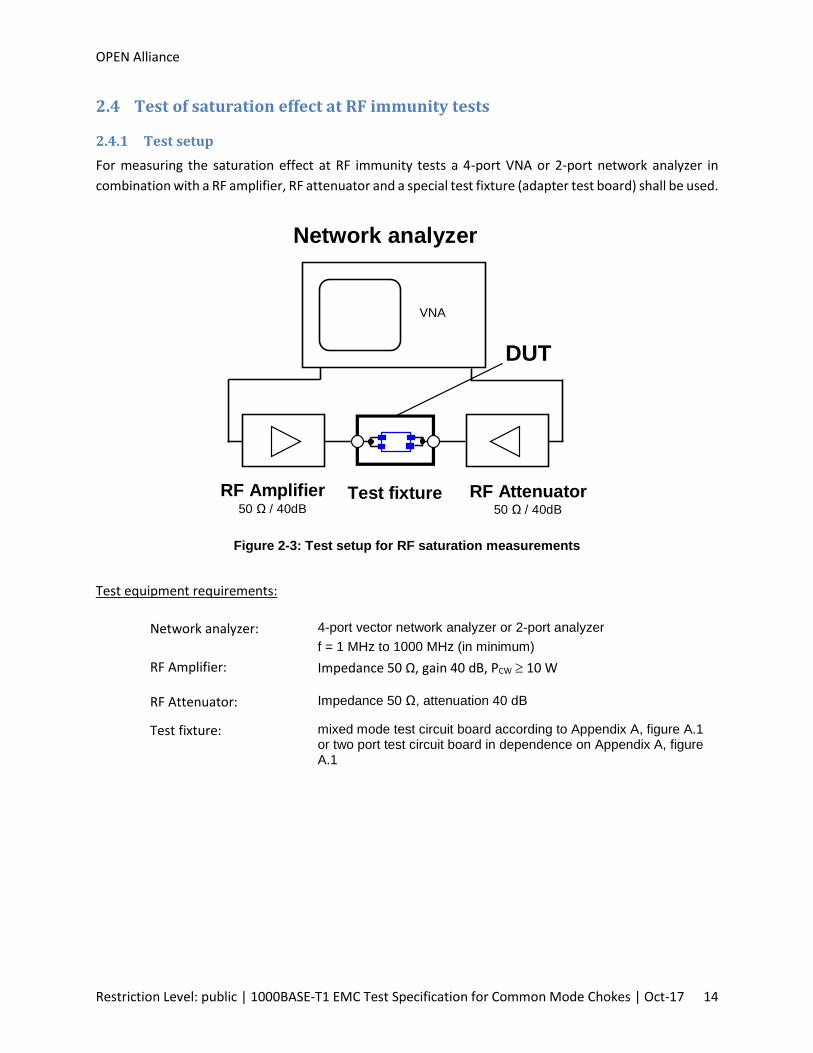
2.4 Test of saturation effect at RF immunity tests
2.4.1 Test setup
For measuring the saturation effect at RF immunity tests a 4-port VNA or 2-port network analyzer in
combination with a RF amplifier, RF attenuator and a special test fixture (adapter test board) shall be used.
VNA
Test fixture
Network analyzer
DUT
RF Attenuator 50 Ω / 40dB
RF Amplifier 50 Ω / 40dB
Figure 2-3: Test setup for RF saturation measurements
Test equipment requirements:
Network analyzer: 4-port vector network analyzer or 2-port analyzer
f = 1 MHz to 1000 MHz (in minimum)
RF Amplifier: Impedance 50 Ω, gain 40 dB, PCW 10 W
RF Attenuator: Impedance 50 Ω, attenuation 40 dB
Test fixture: mixed mode test circuit board according to Appendix A, figure A.1 or two port test circuit board in dependence on Appendix A, figure A.1

OPEN Alliance
Restriction Level: public | 1000BASE-T1 EMC Test Specification for Common Mode Chokes | Oct-17 15
2.4.2 Test procedure and parameters
The required tests are defined in Table 2-5 and should be done on one sample.
Parameter Description
Frequency range: 1 MHz to 1 GHz
S-Parameter power level: S21 (CMR), log. Magnitude in dB / transceiver side
VNA measurement test
circuit:
Port definitions:
Logic port 1: physical port 1 / transceiver side
Logic port 2: physical port 2 / connector side
Pin 1 of CMC is placed on transceiver side (logic port 1)
S21 measurement:
50 Ω input impedance at each measurement port
Single ended VNA Port 2
(50 Ohm)
DUT
1
Single ended VNA Port 1
(50 Ohm)
Test power level: Forward power:
24 dBm, 30 dBm, 36 dBm (applied to DUT)
Dwell time per power
level:
60 s
Evaluation of saturation
effect:
Maximum deviation of 1 dB for power levels 30 dBm and 36 dBm from
reference value for 24 dBm
Test procedure: 1. Test with power level 24 dBm for setting the reference value
2. Test with power level 30 dBm and evaluation
3. Test with power level 36 dBm and evaluation
Table 2-5: Test parameters for RF saturation measurements

OPEN Alliance
Restriction Level: public | 1000BASE-T1 EMC Test Specification for Common Mode Chokes | Oct-17 16
The tests shall be performed and documented according the scheme given in Table 2-6.
Test S- Parameter Sample
RFS S21 (CMR) 1 sample
Table 2-6: Required RF saturation measurements
The CMC must withstand the RF power saturation test according to the evaluation criteria. Recommended
limits are given in Appendix B.3.

OPEN Alliance
Restriction Level: public | 1000BASE-T1 EMC Test Specification for Common Mode Chokes | Oct-17 17
Appendix A - Test fixtures
A.1 General requirements for test fixtures
A printed circuit board design with RF board-to-coax connectors shall be used for all test fixtures. To
ensure reliable RF parameters of the test fixture, a PCB with at least two layers with enlarged GND
reference plane is required. The traces on the test board should be designed as 50 (+/- 5) Ohm single
ended transmission line with a length as short as possible. For design of CMC footprint and the definition
of minimal distance of CMC housing and CMC terminals to the GND plane the related specification of CMC
manufacturer have to be meet.
For S-Parameter 3-Port test fixture additional specific requirements are defined in section A.2.
In general the test fixture design and the method of connecting the CMC with the test fixture shall allow
high accuracy and reproducible test results.
A.2 Self-balance requirements for S-Parameter test fixture
The 3-Port test fixture (test circuit board with soldered RF connectors) used for balance measurement
shall have a very high grade of self-balance.
To prove the test fixture self-balance characteristic, the test parameter and requirements given in Table
A-1 are defined.
To ensure the test fixture self-balance characteristic of symmetrical network at logical port 2 (common
mode), the traces between the DUT and all resistors (R1, R2 and R3) must kept highly symmetric and as
short as possible.
OPEN Alliance
Restriction Level: public | 1000BASE-T1 EMC Test Specification for Common Mode Chokes | Oct-17 18
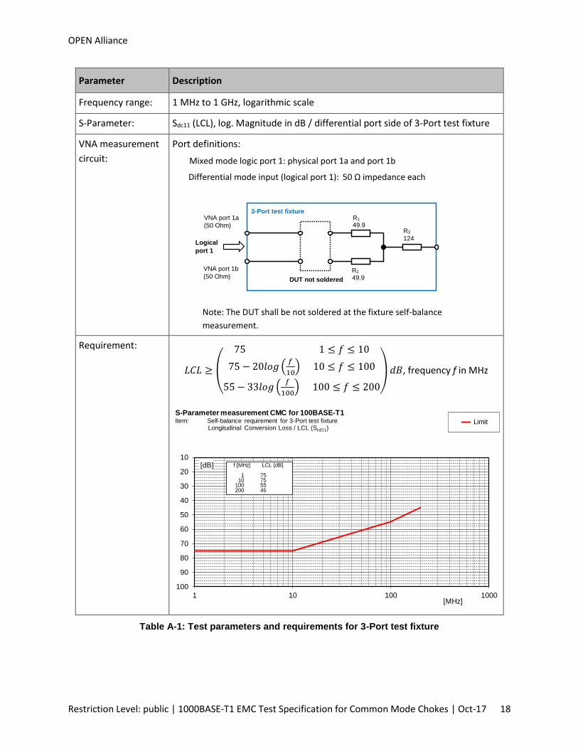
Parameter Description
Frequency range: 1 MHz to 1 GHz, logarithmic scale
S-Parameter: Sdc11 (LCL), log. Magnitude in dB / differential port side of 3-Port test fixture
VNA measurement
circuit:
Port definitions:
Mixed mode logic port 1: physical port 1a and port 1b
Differential mode input (logical port 1): 50 Ω impedance each
124
49.9
49.9 DUT not soldered
VNA port 1a
(50 Ohm)
VNA port 1b
(50 Ohm)
Logical
port 1
3-Port test fixture R1
R2
R3
Note: The DUT shall be not soldered at the fixture self-balance
measurement.
Requirement:
𝐿𝐶𝐿 ≥
(
75 1 ≤ 𝑓 ≤ 10
75 − 20𝑙𝑜𝑔 (𝑓
10) 10 ≤ 𝑓 ≤ 100
55 − 33𝑙𝑜𝑔 (𝑓
100) 100 ≤ 𝑓 ≤ 200)
𝑑𝐵, frequency f in MHz
Table A-1: Test parameters and requirements for 3-Port test fixture
10
20
30
40
50
60
70
80
90
100
1 10 100 1000
Limit
[dB]
[MHz]
S-Parameter measurement CMC for 100BASE-T1Item: Self-balance requirement for 3-Port test fixture
Longitudinal Conversion Loss / LCL (Scd11)
f [MHz] LCL [dB]
1 7510 75
100 55200 45
OPEN Alliance
Restriction Level: public | 1000BASE-T1 EMC Test Specification for Common Mode Chokes | Oct-17 19
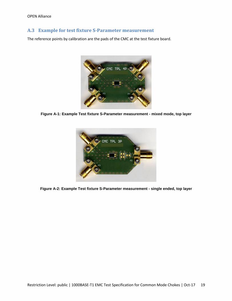
A.3 Example for test fixture S-Parameter measurement
The reference points by calibration are the pads of the CMC at the test fixture board.
Figure A-1: Example Test fixture S-Parameter measurement - mixed mode, top layer
Figure A-2: Example Test fixture S-Parameter measurement - single ended, top layer

OPEN Alliance
Restriction Level: public | 1000BASE-T1 EMC Test Specification for Common Mode Chokes | Oct-17 20
A.4 Example for test fixture ESD tests
The reference points by calibration are the input of RF connector (SMA) at the test fixture board.
Figure A-3: Example Test fixture ESD tests, top layer
Note: For ESD tests the serial jumpers JP1 and JP2 are left open and the resistors R1 and R2 are placed.
For S-Parameter measurement the jumpers JP1 and JP2 are closed and the resistors R1 and R2 are not placed.
R1 DP1
DP2 R2
JP1
JP2

OPEN Alliance
Restriction Level: public | 1000BASE-T1 EMC Test Specification for Common Mode Chokes | Oct-17 21
Appendix B – Recommended limits for tests
B.1 S-Parameter measurements
For evaluation of mixed mode S-Parameters limits given in Figure B-1 through Figure B-4 are
recommended. The limits are valid for test cases S1 through S8.
𝑅𝐿 ≥ (27 1 ≤ 𝑓 ≤ 10
27 − 9.75𝑙𝑜𝑔 (𝑓
10) 10 ≤ 𝑓 ≤ 66
)𝑑𝐵, frequency f in MHz
Figure B-1: Recommended limits for Sdd11 and Sdd22 (RL)
0
10
20
30
40
50
60
1 10 100 1000
Limit
[dB]
[MHz]
S-Parameter measurement CMC for 100BASE-T1 Item: RL (Sdd11,Sdd22)
f [MHz] RL [dB]
1 2710 2766 19

OPEN Alliance
Restriction Level: public | 1000BASE-T1 EMC Test Specification for Common Mode Chokes | Oct-17 22
𝐼𝐿 ≤
(
0.5 1 ≤ 𝑓 ≤ 10
0.5 + 0.39𝑙𝑜𝑔 (𝑓
10) 10 ≤ 𝑓 ≤ 33
0.8 + 1.00𝑙𝑜𝑔 (𝑓
33) 33 ≤ 𝑓 ≤ 66)
𝑑𝐵, frequency f in MHz
Figure B-2: Recommended limits for Sdd21 (IL)
𝐶𝑀𝑅 ≥
(
25 + 20𝑙𝑜𝑔 (𝑓
1) 1 ≤ 𝑓 ≤ 10
45 10 ≤ 𝑓 ≤ 80
45 − 20𝑙𝑜𝑔 (𝑓
80) 80 ≤ 𝑓 ≤ 200)
𝑑𝐵, frequency f in MHz
Figure B-3: Recommended limits for Scc21 (CMR)
-1,0
0,0
1,0
2,0
3,0
4,0
5,0
1 10 100 1000
Limit
[dB]
[MHz]
S-Parameter measurement CMC for 100BASE-T1Item: IL (Sdd21)
f [MHz] IL [dB]
1 0.510 0.533 0.766 1.0
0
10
20
30
40
50
60
1 10 100 1000
Limit
[dB]
[MHz]
S-Parameter measurement CMC for 100BASE-T1Item: Common mode Rejection (Scc21)
f [MHz] CMR [dB]
1 2510 4580 45
200 37

OPEN Alliance
Restriction Level: public | 1000BASE-T1 EMC Test Specification for Common Mode Chokes | Oct-17 23
𝐷𝐶𝑀𝑅𝐶𝐷𝑀𝑅
≥
(
70 1 ≤ 𝑓 ≤ 10
70 − 20𝑙𝑜𝑔 (𝑓
10) 10 ≤ 𝑓 ≤ 100
50 − 33𝑙𝑜𝑔 (𝑓
100) 100 ≤ 𝑓 ≤ 200)
𝑑𝐵, frequency f in MHz
Figure B-4: Recommended limits for Ssd21, Ssd12 (DCMR) and Sds21, Sds12 (CDMR)
10
20
30
40
50
60
70
80
90
100
1 10 100 1000
Limit
[dB]
[MHz]
S-Parameter measurement CMC for 100BASE-T1Item: Common to Differential mode Rejection (Sds21,Sds12)
Differential to Common mode Rejection (Ssd21,Ssd12)
f [MHz] CDMR/DCMR[dB]
1 7010 70
100 50200 40

OPEN Alliance
Restriction Level: public | 1000BASE-T1 EMC Test Specification for Common Mode Chokes | Oct-17 24
B.2 Damage from ESD
It is recommended that the CMC must withstand the ESD discharge with discharge voltage amplitude of
+/- 8 kV without damage.
B.3 Test of saturation effect at RF immunity tests
It is recommended that the CMC must withstand the RF power saturation test with a power amplitude of
36 dBm.

OPEN Alliance
Restriction Level: public | 1000BASE-T1 EMC Test Specification for Common Mode Chokes | Oct-17 25
Appendix C – TDR measurement of differential mode impedance
(informative)
C.1 Test setup
For measuring the differential mode impedance of the CMC a two-channel TDR test equipment in
combination with a special test fixture (adapter test board) shall be used.
Test fixture
TDR test equipment
DUT
Figure C-1: Test setup for TDR measurements
Test equipment requirements:
TDR measurement
system:
Type: 2 channel differential mode
System impedance: 50 single ended / 100 differential mode
Rise time: 25 ps internal ( 100 ps at test fixture)
Test fixture: Use test fixture from 4 port S-Parameter measurements

OPEN Alliance
Restriction Level: public | 1000BASE-T1 EMC Test Specification for Common Mode Chokes | Oct-17 26
C.2 Test procedure and parameters
The required measurements are defined in Table C-1 and should be done on one sample.
Parameter Description
TDR measurement circuit: Definition:
Pin 1 of CMC is placed on the transceiver side (TDR measurement port)
TDR Port 1
(50 Ohm)
TDR Port 2
(50 Ohm)
DUT
Termination to GND
(open/50 Ohm)
Termination to GND
(open/50 Ohm)
1
Note: The TDR shall be deskewed at the CMC terminals.
Table C-1: Test parameters for TDR measurements
The measurements shall be performed and documented according the scheme given in Table C-2.
Test Parameter Sample
T1 Differential mode impedance 1 sample
Table C-2: Required TDR measurements
There is no recommendation for limit. This test is only for information purpose and can be used for
additional interpretation of results of S-Parameter measurements.
=== END OF DOCUMENT ===