Embed Size (px)
DESCRIPTION
A HMI (HMI - Human Machine Interface) fornece uma série de novos recursos para o inversor de freqüência de média tensão MVW-01.
Citation preview
Graphic HMI Interface
MVW-01 V1.7X
Installation, Operation and Configuration Guide
Language: English
Document: 10000310738 / 00
Motors | Energy | Automation | Coatings

Summary
SUMMARY
1 INTRODUCTION ........................................................................................41.1 INSTALLATION OF THE GRAPHIC HMI IN THE CABINET .............................. 4
2 STARTING THE USE OF THE GRAPHIC HMI .........................................62.1 GRAPHIC HMI BASIC VISUALIZATION MODES .............................................. 72.2 STRUCTURE OF THE PARAMETER GROUPS ................................................. 8
2.2.1 Sequential Access Mode ......................................................................... 92.2.2 Parameter Groups Access Mode ........................................................... 9
3 PARAMETER EDITION ............................................................................ 113.1 NUMERICAL .......................................................................................................113.2 ALPHANUMERICAL ...........................................................................................11
4 CONFIGURING THE GRAPHIC HMI ...................................................... 124.1 LCD CONTRAST .................................................................................................124.2 CONFIGURING THE HMI COMMANDS ...........................................................124.3 CONFIGURING THE MONITORING MODE READ-ONLY PARAMETERS ....134.4 CONFIGURING THE ON-LINE GRAPHIC (WATCH) FUNCTION ....................13
5 ALARMS AND FAULTS ........................................................................... 145.1 ALARM/FAULT SCREEN ...................................................................................145.2 NOTE SCREEN ...................................................................................................155.3 ERROR LOG ........................................................................................................15
6 HELP FUNCTION .....................................................................................16
7 GRAPHIC HMI PARAMETER DESCRIPTION ........................................ 17
4 | MVW-01
Graphic HMI Interface
1 INTRODUCTION
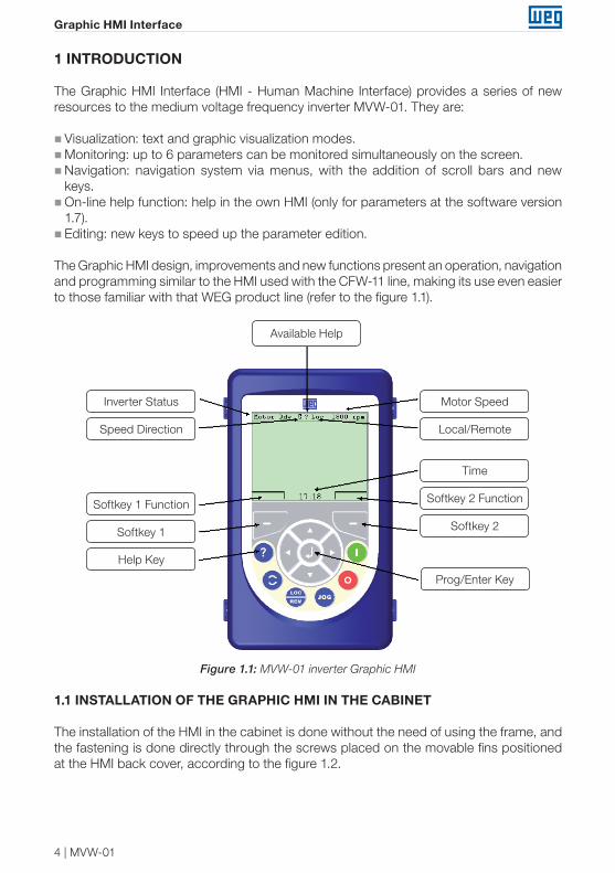
The Graphic HMI Interface (HMI - Human Machine Interface) provides a series of new resources to the medium voltage frequency inverter MVW-01. They are:
� Visualization: text and graphic visualization modes. �Monitoring: up to 6 parameters can be monitored simultaneously on the screen. �Navigation: navigation system via menus, with the addition of scroll bars and new keys. �On-line help function: help in the own HMI (only for parameters at the software version 1.7). � Editing: new keys to speed up the parameter edition.
The Graphic HMI design, improvements and new functions present an operation, navigation and programming similar to the HMI used with the CFW-11 line, making its use even easier to those familiar with that WEG product line (refer to the figure 1.1).
Motor Speed
Local/Remote
Softkey 2 Function
Softkey 2
Prog/Enter Key
Time
Available Help
Inverter Status
Speed Direction
Softkey 1 Function
Softkey 1
Help Key
Figure 1.1: MVW-01 inverter Graphic HMI
1.1 INSTALLATION OF THE GRAPHIC HMI IN THE CABINET
The installation of the HMI in the cabinet is done without the need of using the frame, and the fastening is done directly through the screws placed on the movable fins positioned at the HMI back cover, according to the figure 1.2.
MVW-01 | 5
Graphic HMI Interface
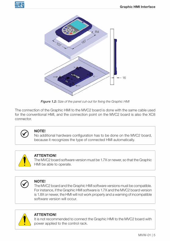
107 187
R4
16
Figure 1.2: Size of the panel cut-out for fixing the Graphic HMI
The connection of the Graphic HMI to the MVC2 board is done with the same cable used for the conventional HMI, and the connection point on the MVC2 board is also the XC8 connector.
NOTE!No additional hardware configuration has to be done on the MVC2 board, because it recognizes the type of connected HMI automatically.
ATTENTION!The MVC2 board software version must be 1.7X or newer, so that the Graphic HMI be able to operate.
NOTE!The MVC2 board and the Graphic HMI software versions must be compatible. For instance, if the Graphic HMI software is 1.7X and the MVC2 board version is 1.8X or newer, the HMI will not work properly and a warning of incompatible software version will occur.
ATTENTION!It is not recommended to connect the Graphic HMI to the MVC2 board with power applied to the control rack.
6 | MVW-01
Graphic HMI Interface
2 STARTING THE USE OF THE GRAPHIC HMI
The communication between the Graphic HMI and the inverter is established with the Modbus RTU protocol (38400 bps, no parity, with 2 stop bits), using as the physical layer the RS485 channel. The Graphic HMI works as the communication master.
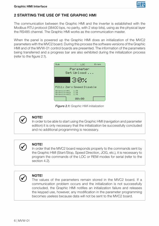
When the panel is powered up the Graphic HMI does an initialization of the MVC2 parameters with the MVC2 board. During this process the software versions of the Graphic HMI and of the MVW-01 control boards are presented. The information of the parameters being transferred and a progress bar are also exhibited during the initialization process (refer to the figure 2.1).
Sub LOC 0 rpm
00:00
Parameter Set Upload ...
P211: Zero Speed Disable
30%
SW Version HMI 1.70SW Version MVC2 1.70SW Version MVC1 1.70
Figure 2.1: Graphic HMI initialization
NOTE!In order to be able to start using the Graphic HMI (navigation and parameter edition) it is only necessary that the initialization be successfully concluded and no additional programming is necessary.
NOTE!In order that the MVC2 board responds properly to the commands sent by the Graphic HMI (Start/Stop, Speed Direction, JOG, etc.), it is necessary to program the commands of the LOC or REM modes for serial (refer to the section 4.2).
NOTE!The values of the parameters remain stored in the MVC2 board. If a communication problem occurs and the initialization is not successfully concluded, the Graphic HMI notifies an initialization failure and releases the keypad use, however, any modification in the parameter programming becomes useless because data will not be sent to the MVC2 board.
MVW-01 | 7
Graphic HMI Interface
NOTE!If the Graphic HMI is disconnected while the panel is with power, when reconnecting it a new initialization procedure occurs.
2.1 GRAPHIC HMI BASIC VISUALIZATION MODES
In any HMI use situation (visualization mode or active screen) there are standard indications that always will be presented (refer to the figure 1.1):
�Header:- Inverter Status- Speed Direction- Help Availability- Local or Remote Mode- Motor Speed (rpm) � Footer:- Time- Function of the 2 Softkeys
The various modes or visualization screens of the Graphic HMI can be classified into 6 distinct basic types:
�Read-only parameters:- 1 parameter- 2 or 3 parameters- 4 to 6 parameters �Navigation:- Parameter Groups- Parameters- Error Log � Parameter edition:- Numerical Parameters- Alphanumerical Parameters � Indication of occurred fault, alarm or notification. �Help Function (only for parameters in this software version). �Graphic functions:- Watch Function- Trace Function (function not implemented in this software version)
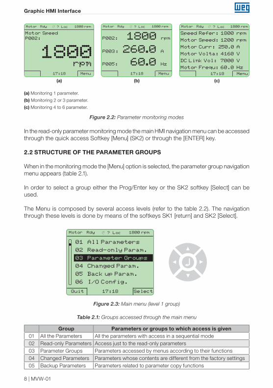
When the initialization is finished the display enters the parameter monitoring mode. The number of presented parameters can be programmed through the read-only parameter selection parameters (P500 to P505, refer to the section 4.3 for more details), and the font size varies according to the number of parameters programmed for monitoring, according to the figure 2.2.
8 | MVW-01
Graphic HMI Interface
Motor Rdy ? Loc 1800 rpm
17:18 Menu
Motor SpeedP002:
rpm1800
Motor Rdy ? Loc 1800 rpm
17:18 Menu
P002: 1800 rpm
P003: 260.0 A
P005: 60.0 Hz
Motor Rdy ? Loc 1800 rpm
17:18 Menu
Speed Refer: 1800 rpm
Motor Speed: 1200 rpm
Motor Curr: 250.0 A
Motor Volta: 4160 V
DC Link Vol: 7000 V
Motor Frequ: 60.0 Hz
(a) (b) (c)
(a) Monitoring 1 parameter.
(b) Monitoring 2 or 3 parameter.
(c) Monitoring 4 to 6 parameter.
Figure 2.2: Parameter monitoring modes
In the read-only parameter monitoring mode the main HMI navigation menu can be accessed through the quick access Softkey [Menu] (SK2) or through the [ENTER] key.
2.2 STRUCTURE OF THE PARAMETER GROUPS
When in the monitoring mode the [Menu] option is selected, the parameter group navigation menu appears (table 2.1).
In order to select a group either the Prog/Enter key or the SK2 softkey [Select] can be used.
The Menu is composed by several access levels (refer to the table 2.2). The navigation through these levels is done by means of the softkeys SK1 [return] and SK2 [Select].
Motor Rdy ? Loc 1800 rpm
17:18 SelectQuit
01 All Parameters
02 Read-only Param.
03 Parameter Groups
04 Changed Param.
05 Back up Param.
06 I/O Config.
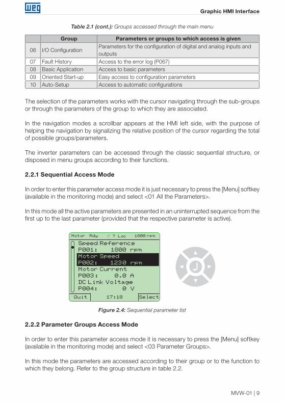
Figure 2.3: Main menu (level 1 group)
Table 2.1: Groups accessed through the main menu
Group Parameters or groups to which access is given01 All the Parameters All the parameters with access in a sequential mode02 Read-only Parameters Access just to the read-only parameters03 Parameter Groups Parameters accessed by menus according to their functions 04 Changed Parameters Parameters whose contents are different from the factory settings 05 Backup Parameters Parameters related to parameter copy functions
MVW-01 | 9
Graphic HMI Interface
Group Parameters or groups to which access is given
06 I/O ConfigurationParameters for the configuration of digital and analog inputs and outputs
07 Fault History Access to the error log (P067)08 Basic Application Access to basic parameters09 Oriented Start-up Easy access to configuration parameters10 Auto-Setup Access to automatic configurations
The selection of the parameters works with the cursor navigating through the sub-groups or through the parameters of the group to which they are associated.
In the navigation modes a scrollbar appears at the HMI left side, with the purpose of helping the navigation by signalizing the relative position of the cursor regarding the total of possible groups/parameters.
The inverter parameters can be accessed through the classic sequential structure, or disposed in menu groups according to their functions.
2.2.1 Sequential Access Mode
In order to enter this parameter access mode it is just necessary to press the [Menu] softkey (available in the monitoring mode) and select <01 All the Parameters>.
In this mode all the active parameters are presented in an uninterrupted sequence from the first up to the last parameter (provided that the respective parameter is active).
Motor Rdy ? Loc 1800 rpm
17:18 SelectQuit
Speed ReferenceP001: 1800 rpmMotor SpeedP002: 1230 rpmMotor CurrentP003: 0.0 ADC Link VoltageP004: 0 V
Figure 2.4: Sequential parameter list
2.2.2 Parameter Groups Access Mode
In order to enter this parameter access mode it is necessary to press the [Menu] softkey (available in the monitoring mode) and select <03 Parameter Groups>.
In this mode the parameters are accessed according to their group or to the function to which they belong. Refer to the group structure in table 2.2.
Table 2.1 (cont.): Groups accessed through the main menu
10 | MVW-01
Graphic HMI Interface
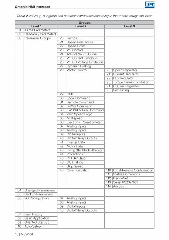
Table 2.2: Group, subgroup and parameter structures according to the various navigation levels
GroupsLevel 1 Level 2 Level 3
01 All the Parameters02 Read-only Parameters03 Parameter Groups 20 Ramps
21 Speed References22 Speed Limits23 V/F Control24 Adjustable V/F Curve25 V/F Current Limitation26 V/F DC Voltage Limitation27 Dynamic Braking28 Vector Control 90 Speed Regulator
91 Current Regulator92 Flux Regulator93 Torque Current Limitation94 DC Link Regulator95 Self-Tuning
29 HMI30 Local Command31 Remote Command 32 3-Wire Command33 FWD/REV Run Command34 Zero Speed Logic35 Multispeed36 Electronic Potentiometer 37 Analog Inputs38 Analog Inputs39 Digital Inputs40 Digital/Relay Outputs41 Inverter Data42 Motor Data43 Flying Start/Ride-Through44 Protections45 PID Regulator46 DC Braking47 Skip Speed48 Communication 110 Local/Remote Configuration
111 Status/Commands112 DeviceNet113 Serial RS232/485114 Anybus
04 Changed Parameters05 Backup Parameters06 I/O Configuration 37 Analog Inputs
38 Analog Inputs39 Digital Inputs40 Digital/Relay Outputs
07 Fault History08 Basic Application09 Oriented Start-up10 Auto-Setup
MVW-01 | 11
Graphic HMI Interface
Motor Rdy ? Loc 1800 rpm
17:18 SelectQuit
20 Ramps
21 Speed Reference
22 Speed Limits
23 V/F Control
24 Adjust V/F Curve
25 V/F Current Lim.
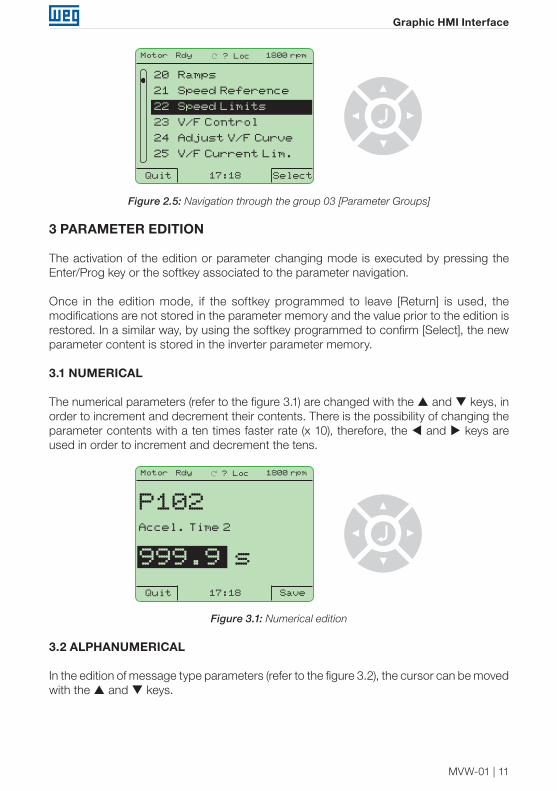
Figure 2.5: Navigation through the group 03 [Parameter Groups]
3 PARAMETER EDITION
The activation of the edition or parameter changing mode is executed by pressing the Enter/Prog key or the softkey associated to the parameter navigation.
Once in the edition mode, if the softkey programmed to leave [Return] is used, the modifications are not stored in the parameter memory and the value prior to the edition is restored. In a similar way, by using the softkey programmed to confirm [Select], the new parameter content is stored in the inverter parameter memory.
3.1 NUMERICAL
The numerical parameters (refer to the figure 3.1) are changed with the and keys, in order to increment and decrement their contents. There is the possibility of changing the parameter contents with a ten times faster rate (x 10), therefore, the and keys are used in order to increment and decrement the tens.
Motor Rdy ? Loc 1800 rpm
17:18 SaveQuit
P102Accel. Time 2
999.9 s
Figure 3.1: Numerical edition
3.2 ALPHANUMERICAL
In the edition of message type parameters (refer to the figure 3.2), the cursor can be moved with the and keys.
12 | MVW-01
Graphic HMI Interface
Motor Rdy ? Loc 1800 rpm
17:18 SaveQuit
P202Type of Control
[000] V/F 60Hz[001] V/F 50Hz[002] V/F Adjust[003] Sensorless[004] Encoder
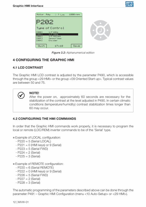
Figure 3.2: Alphanumerical edition
4 CONFIGURING THE GRAPHIC HMI
4.1 LCD CONTRAST
The Graphic HMI LCD contrast is adjusted by the parameter P490, which is accessible through the group <29 HMI> or the group <09 Oriented Start-up>. Typical contrast values are between 50 and 75.
NOTE!After the power on, approximately 60 seconds are necessary for the stabilization of the contrast at the level adjusted in P490. In certain climatic conditions (temperature/humidity) contrast stabilization times longer than 60 may occur.
4.2 CONFIGURING THE HMI COMMANDS
In order that the Graphic HMI commands work properly, it is necessary to program the local or remote (LOC/REM) inverter commands to be of the ‘Serial’ type.
� Example of LOCAL configuration:- P220 = 5 (Serial LOCAL)- P221 = 0 (HMI keys) or 9 (Serial)- P223 = 5 (Serial FWD)- P224 = 2 (Serial)- P225 = 3 (Serial)
� Example of REMOTE configuration:- P220 = 6 (Serial REMOTE)- P222 = 0 (HMI keys) or 9 (Serial)- P226 = 5 (Serial FWD)- P227 = 2 (Serial)- P228 = 3 (Serial)
The automatic programming of the parameters described above can be done through the parameter P491 – Graphic HMI Configuration (menu <10 Auto-Setup> or <29 HMI>).
MVW-01 | 13
Graphic HMI Interface
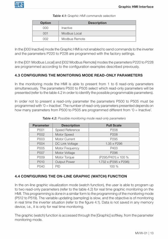
Table 4.1: Graphic HMI commands selection
Option Description
000 Inactive
001 Modbus Local
002 Modbus Remote
In the [000 Inactive] mode the Graphic HMI is not enabled to send commands to the inverter and the parameters P220 to P228 are programmed with the factory settings.
In the [001 Modbus Local] and [002 Modbus Remote] modes the parameters P220 to P228 are programmed according to the configuration examples described previously.
4.3 CONFIGURING THE MONITORING MODE READ-ONLY PARAMETERS
In the monitoring mode the HMI is able to present from 1 to 6 read-only parameters simultaneously. The parameters P500 to P505 select which read-only parameters will be presented (refer to the table 4.2 in order to identify the possible programmable parameters).
In order not to present a read-only parameter the parameters P500 to P505 must be programmed with ‘0 = Inactive’. The number of read-only parameters presented depends on how many parameters from P500 to P505 are programmed different from ‘0 = Inactive’.
Table 4.2: Possible monitoring mode read-only parameters
Parameter Description Full ScaleP001 Speed Reference P208P002 Motor Speed P208P003 Motor Current P295P004 DC Link Voltage 1.35 x P296P005 Motor Frequency P403P007 Motor Voltage P296P009 Motor Torque (P295/P401) x 100 %P010 Output Power 1.732 x (P295 x P296)P040 PID 100 %
4.4 CONFIGURING THE ON-LINE GRAPHIC (WATCH) FUNCTION
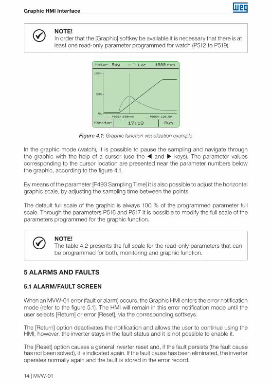
In the on-line graphic visualization mode (watch function), the user is able to program up to two read-only parameters (refer to the table 4.2) for real time graphic monitoring on the HMI. This programming is done in a similar form to the programming of the monitoring mode (P512 to P519). The variable updating (sampling) is slow, and the objective is of monitoring in real time the inverter situation (refer to the figure 4.1). Data is not saved in any memory device, i.e., it is only for real time monitoring.
The graphic (watch) function is accessed through the [Graphic] softkey, from the parameter monitoring mode.
14 | MVW-01
Graphic HMI Interface
NOTE!In order that the [Graphic] softkey be available it is necessary that there is at least one read-only parameter programmed for watch (P512 to P519).
Motor Rdy ? Loc 1800 rpm
17:18Monitor Run
0%P002= 300rpm P003= 120.0A
50%
100%
Figure 4.1: Graphic function visualization example
In the graphic mode (watch), it is possible to pause the sampling and navigate through the graphic with the help of a cursor (use the and keys). The parameter values corresponding to the cursor location are presented near the parameter numbers below the graphic, according to the figure 4.1.
By means of the parameter [P493 Sampling Time] it is also possible to adjust the horizontal graphic scale, by adjusting the sampling time between the points.
The default full scale of the graphic is always 100 % of the programmed parameter full scale. Through the parameters P516 and P517 it is possible to modify the full scale of the parameters programmed for the graphic function.
NOTE!The table 4.2 presents the full scale for the read-only parameters that can be programmed for both, monitoring and graphic function.
5 ALARMS AND FAULTS
5.1 ALARM/FAULT SCREEN
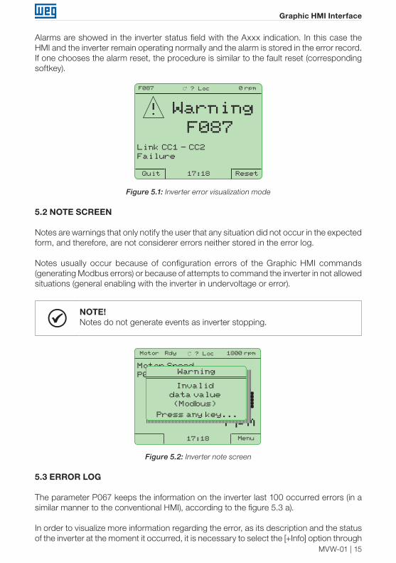
When an MVW-01 error (fault or alarm) occurs, the Graphic HMI enters the error notification mode (refer to the figure 5.1). The HMI will remain in this error notification mode until the user selects [Return] or error [Reset], via the corresponding softkeys.
The [Return] option deactivates the notification and allows the user to continue using the HMI, however, the inverter stays in the fault status and it is not possible to enable it.
The [Reset] option causes a general inverter reset and, if the fault persists (the fault cause has not been solved), it is indicated again. If the fault cause has been eliminated, the inverter operates normally again and the fault is stored in the error record.
MVW-01 | 15
Graphic HMI Interface
Alarms are showed in the inverter status field with the Axxx indication. In this case the HMI and the inverter remain operating normally and the alarm is stored in the error record. If one chooses the alarm reset, the procedure is similar to the fault reset (corresponding softkey).
17:18Quit Reset
WarningF087
Link CC1 - CC2Failure
F087 ? Loc 0 rpm
!
Figure 5.1: Inverter error visualization mode
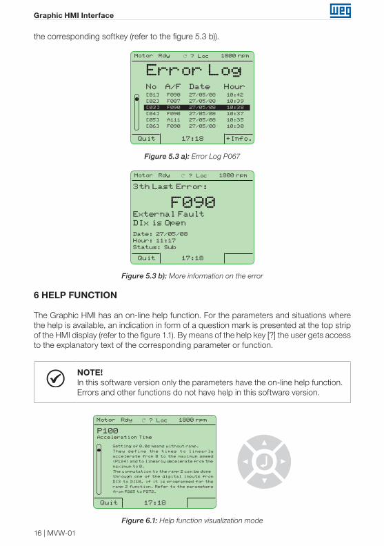
5.2 NOTE SCREEN
Notes are warnings that only notify the user that any situation did not occur in the expected form, and therefore, are not considerer errors neither stored in the error log.
Notes usually occur because of configuration errors of the Graphic HMI commands (generating Modbus errors) or because of attempts to command the inverter in not allowed situations (general enabling with the inverter in undervoltage or error).
NOTE!Notes do not generate events as inverter stopping.
180017:18 Menu
Motor SpeedP002:
rpm
Motor Rdy ? Loc 1800 rpm
Warning
Invalid data value(Modbus)
Press any key...
Figure 5.2: Inverter note screen
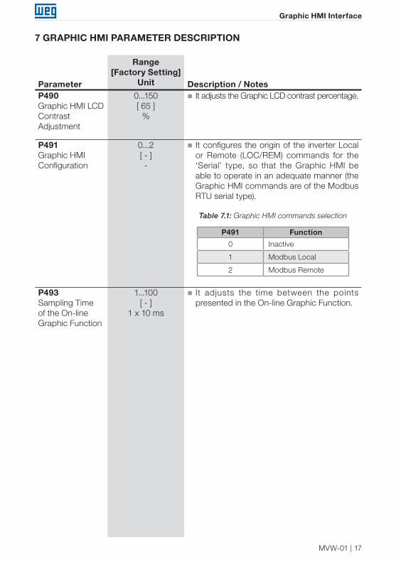
5.3 ERROR LOG
The parameter P067 keeps the information on the inverter last 100 occurred errors (in a similar manner to the conventional HMI), according to the figure 5.3 a).
In order to visualize more information regarding the error, as its description and the status of the inverter at the moment it occurred, it is necessary to select the [+Info] option through
16 | MVW-01
Graphic HMI Interface
the corresponding softkey (refer to the figure 5.3 b)).
Motor Rdy ? Loc 1800 rpm
17:18 +Info.Quit
Error LogNo A/F Date Hour[01] F090 27/05/08 10:42
[02] F087 27/05/08 10:39
[03] F090 27/05/08 10:38
[04] F090 27/05/08 10:37
[05] A111 27/05/08 10:35
[06] F090 27/05/08 10:30
Figure 5.3 a): Error Log P067
Motor Rdy ? Loc 1800 rpm
17:18Quit
3th Last Error:
F090External FaultDIx is Open
Date: 27/05/08Hour: 11:17Status: Sub
Figure 5.3 b): More information on the error
6 HELP FUNCTION
The Graphic HMI has an on-line help function. For the parameters and situations where the help is available, an indication in form of a question mark is presented at the top strip of the HMI display (refer to the figure 1.1). By means of the help key [?] the user gets access to the explanatory text of the corresponding parameter or function.
NOTE!In this software version only the parameters have the on-line help function. Errors and other functions do not have help in this software version.
Motor Rdy ? Loc 1800 rpm
17:18Quit
Setting of 0.0s means without ramp.
They define the times to linearly
accelerate from 0 to the maximum speed
(P134) and to linearly decelerate from the
maximum to 0.
The commutation to the ramp 2 can be done
through one of the digital inputs from
DI3 to DI10, if it is programmed for the
ramp 2 function. Refer to the parameters
from P265 to P272.
P100Acceleration Time
Figure 6.1: Help function visualization mode
MVW-01 | 17
Graphic HMI Interface
7 GRAPHIC HMI PARAMETER DESCRIPTION
Parameter
Range[Factory Setting]
Unit Description / NotesP490Graphic HMI LCD Contrast Adjustment
0...150[ 65 ]
%
� It adjusts the Graphic LCD contrast percentage.
P491Graphic HMI Configuration
0...2[ - ]-
� It configures the origin of the inverter Local or Remote (LOC/REM) commands for the ‘Serial’ type, so that the Graphic HMI be able to operate in an adequate manner (the Graphic HMI commands are of the Modbus RTU serial type).
Table 7.1: Graphic HMI commands selection
P491 Function
0 Inactive
1 Modbus Local
2 Modbus Remote
P493Sampling Time of the On-line Graphic Function
1...100[ - ]
1 x 10 ms
� It adjusts the time between the points presented in the On-line Graphic Function.
18 | MVW-01
Graphic HMI Interface
Parameter
Range[Factory Setting]
Unit Description / NotesP500Read-only Parameter #1 Selection
P501Read-only Parameter #2 Selection
P502Read-only Parameter #3 Selection
P503Read-only Parameter #4 Selection
P504Read-only Parameter #5 Selection
P505Read-only Parameter #6 Selection
0...9[ 2 ]
-
0...9[ 0 ]
-
0...9[ 0 ]
-
0...9[ 0 ]
-
0...9[ 0 ]
-
0...9[ 0 ]
-
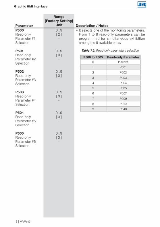
� It selects one of the monitoring parameters. From 1 to 6 read-only parameters can be programmed for simultaneous exhibition among the 9 available ones.
Table 7.2: Read-only parameters selection
P500 to P505 Read-only Parameter
0 Inactive
1 P001
2 P002
3 P003
4 P004
5 P005
6 P007
7 P009
8 P010
9 P040
MVW-01 | 19
Graphic HMI Interface
Parameter
Range[Factory Setting]
Unit Description / NotesP500Read-only Parameter #1 Selection
P501Read-only Parameter #2 Selection
P502Read-only Parameter #3 Selection
P503Read-only Parameter #4 Selection
P504Read-only Parameter #5 Selection
P505Read-only Parameter #6 Selection
0...9[ 2 ]
-
0...9[ 0 ]
-
0...9[ 0 ]
-
0...9[ 0 ]
-
0...9[ 0 ]
-
0...9[ 0 ]
-
� It selects one of the monitoring parameters. From 1 to 6 read-only parameters can be programmed for simultaneous exhibition among the 9 available ones.
Table 7.2: Read-only parameters selection
P500 to P505 Read-only Parameter
0 Inactive
1 P001
2 P002
3 P003
4 P004
5 P005
6 P007
7 P009
8 P010
9 P040
Parameter
Range[Factory Setting]
Unit Description / NotesP512On-line Graphic Function Parameter #1 Selection
P513On-line Graphic Function Parameter #2 Selection
0...9[ 2 ]
-
0...9[ 3 ]
-
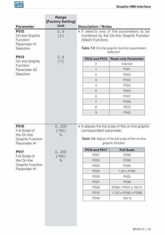
� It selects one of the parameters to be monitored by the On-line Graphic Function (Watch Function).
Table 7.3: On-line graphic function parameters selection
P512 and P513 Read-only Parameter
0 Inactive
1 P001
2 P002
3 P003
4 P004
5 P005
6 P007
7 P009
8 P010
9 P040
P516Full Scale of the On-line Graphic Function Parameter #1
P517Full Scale of the On-line Graphic Function Parameter #1
0…200[ 100 ]
%
0…200[ 100 ]
%
� It adjusts the full scale of the on-line graphic correspondent parameter.
Table 7.4: Adjust of the full scale of the on-line graphic function
P516 and P517 Full Scale
P001 P208
P002 P208
P003 P295
P004 1,35 x P296
P005 P403
P007 P296
P009 (P295 / P401) x 100 %
P010 1,732 x (P295 x P296)
P040 100 %

WEG Automação S.A. Jaraguá do Sul - SC - Brazil Phone 55 (47) 3276-4000 - Fax 55 (47) 3276-4020São Paulo - SP - Brazil Phone 55 (11) 5053-2300 - Fax 55 (11) [email protected] www.weg.net