Embed Size (px)
Citation preview

READ & SAVE THESE INSTRUCTIONS
1000-Lb. Adjustable Gantry Crane
Owner’s Manual
WARNING: Read carefully and understand all ASSEMBLY AND OPERATION
INSTRUCTIONS before operating. Failure to follow the safety rules and other basic safety
precautions may result in serious personal injury.
Item #57020

Page 2 of 22
Thank you very much for choosing a Strongway™ product!
For future reference, please complete the owner’s record below:
Serial Number/Lot Date Code: ________________________________
Purchase Date: ____________________________________________
Save the receipt, warranty, and this manual. It is important that you read
the entire manual to become familiar with this product before you begin
using it.
This gantry crane is designed for certain applications only. Northern Tool
and Equipment is not responsible for issues arising from modification or
improper use of this product such as an application for which it was not
designed. We strongly recommend that this product not be modified
and/or used for any application other than that for which it was designed.
For technical questions, please call 1-800-222-5381.

Page 3 of 22
Table of Contents
Intended Use .......................................................................................................................................... 4
Packaging Contents .............................................................................................................................. 4
Technical Specifications ...................................................................................................................... 4
Important Safety Information ............................................................................................................... 4
Specific Operation Warnings ............................................................................................................... 6
Main Parts of Product ........................................................................................................................... 6
Assembly Instructions .......................................................................................................................... 7
Before Each Use .................................................................................................................................. 12
Operating Instructions ........................................................................................................................ 14
After Each Use ..................................................................................................................................... 16
Maintenance ........................................................................................................................................ 16
Troubleshooting .................................................................................................................................. 18
Parts Diagram ...................................................................................................................................... 19
Parts List .............................................................................................................................................. 20
Replacement Parts .............................................................................................................................. 20
Limited Warranty ................................................................................................................................. 21

Page 4 of 22
Intended Use
This all-steel Strongway’s 1000-Lb. Adjustable Gantry Crane is ideal for shops where lifting is an essential part of the business. It goes where forklifts can’t. Quick assembly and disassembly allow for easy transport within a jobsite or from site to site. Auto-lock feature keeps unit secure. Super-strong casters with rubber roll smoothly. Gantry crane is NOT to be moved while loaded.
Packaging Contents
Part A (3)
I-Beam (1)
Base (2)
Other parts
Technical Specifications
Property Specification
Load Capacity (lb.) 1000
I-Beam to Ground (in.) 95 ½ to 142 3/4
Width (in.) 47 1/4
Flange Width (in.) 94 7/8
I-Beam Height (in.) 86 1/2
Important Safety Information
⚠WARNING
Read and understand all instructions. Failure to follow all instructions may result in serious injury
or property damage.
The warnings, cautions, and instructions in this manual cannot cover all possible conditions or
situations that could occur. Exercise common sense and caution when using this tool. Always be
aware of the environment and ensure that the tool is used in a safe and responsible manner.
Do not allow persons to operate or assemble the product until they have read this manual and
have developed a thorough understanding of how it works.
Do not modify this product in any way. Unauthorized modification may impair the function and/or
safety and could affect the life of the product. There are specific applications for which the product
was designed.
Use the right tool for the job. DO NOT attempt to force small equipment to do the work of larger
industrial equipment. There are certain applications for which this equipment was designed. This
product will be safer and do a better job at the capacity for which it was intended. DO NOT use
this equipment for a purpose for which it was not intended.
Page 5 of 22
Industrial or commercial applications must follow OSHA requirements.
⚠WARNING
WORK AREA SAFETY
Inspect the work area before each use. Keep work area clean, dry, free of clutter, and well-lit.
Cluttered, wet, or dark work areas can result in injury. Using the product in confined work areas
may put you dangerously close to cutting tools and rotating parts.
Do not use the product where there is a risk of causing a fire or an explosion; e.g., in the presence
of flammable liquids, gases, or dust. The product can create sparks, which may ignite the
flammable liquids, gases, or dust.
Keep children and bystanders away from the work area while operating the tool. Do not allow
children to handle the product.
Be aware of all power lines, electrical circuits, water pipes, and other mechanical hazards in your
work area. Some of these hazards may be hidden from your view and may cause personal injury
and/or property damage if contacted.
⚠WARNING
PERSONAL SAFETY
Stay alert, watch what you are doing, and use common sense when operating the tool. Do not use
the tool while you are tired or under the influence of drugs, alcohol, or medication. A moment of
inattention while operating the tool may result in serious personal injury.
Dress properly. Do not wear loose clothing, dangling objects, or jewelry. Keep your hair, clothing
and gloves away from moving parts. Loose clothes, jewelry, or long hair can be caught in moving
parts. Air vents on the tool often cover moving parts and should be avoided.
Wear the proper personal protective equipment when necessary. Use ANSI Z87.1 compliant safety
goggles (not safety glasses) with side shields, or when needed, a face shield. Use a dust mask in
dusty work conditions. Also use non-skid safety shoes, hardhat, gloves, dust collection systems,
and hearing protection when appropriate. This applies to all persons in the work area.
Do not overreach. Keep proper footing and balance at all times.
⚠CAUTION
CRANE USE AND CARE
Do not force the product. Products are safer and do a better job when used in the manner for
which they are designed. Plan your work, and use the correct product for the job.
Check for damaged parts before each use. Carefully check that the product will operate properly
and perform its intended function. Replace damaged or worn parts immediately. Never operate the
product with a damaged part.
Store the product when it is not in use. Store it in a dry, secure place out of the reach of children.
Page 6 of 22
Inspect the tool for good working condition prior to storage and before re-use.
Use only accessories that are recommended by the manufacturer for use with your product.
Accessories that may be suitable for one product may create a risk of injury when used with
another tool. Never use an accessory that has a lower operating speed or operating pressure than
the tool itself.
Specific Operation Warnings
⚠WARNING
To prevent serious injury or property damage, read and understand the owner’s manual before
use.
Do not exceed the rated load capacity.
Operate on a hard, level surface.
Do not operate crane if the beam is not level.
Be sure the trolley stoppers have been fixed to both ends of the beam.
Ensure the load is centered before lifting.
Do not use to lift people or animals.
Keep persons and property clear from under the load.
Do not leave loads suspended when the gantry crane is unattended.
Do not allow the load to swing or roll against the support members.
Inspect the crane for damaged parts and loose bolts before each use.
Do not use the crane if there are damaged parts. Replace damaged parts before continuing use.
Do not adjust height or disassemble crane while loaded.
Secure trolley and hoist in the center of the beam when adjusting height.
Do not push or pull crane with a forklift or other vehicle.
Never push the load when trying to move the crane. Always push the crane.
When moving crane while loaded, keep the load close as close to the floor as possible and
position the load in the center of the beam.
Do not anchor the legs to the floor.
Secure the trolley and hoist in the center of the beam when adjusting the height.
Main Parts of Product
Reference Subassembly
1 4'' Locking Swivel Caster
2 Base
3 Post Sleeve
4 Post Support
5 I-Beam

Page 7 of 22
Reference Subassembly
6 Handle
Assembly Instructions
⚠WARNING
TO PREVENT SERIOUS INJURY AND DEATH: Wear ANSI Z87.1 compliant safety goggles, hard
hat, heavy-duty work gloves, and steel-toed work boots during assembly and operation.
The correct bolts must be used during assembly. If any doubts arise regarding proper assembly,
contact Northern Tool + Equipment before use.
Assembly Set-up
1. More than one person will be needed for assembly.
2. Use a large, clean, and uncluttered area for assembly.
3. Consider vertical clearance when choosing operation area. Assemble close to operation area.
4. Use saw horses (not included) to support larger items such as Posts and I-Beam during assembly.
5. The Post Insert (7) and Post Sleeve (3) are pre-assembled.
Assembly Instructions
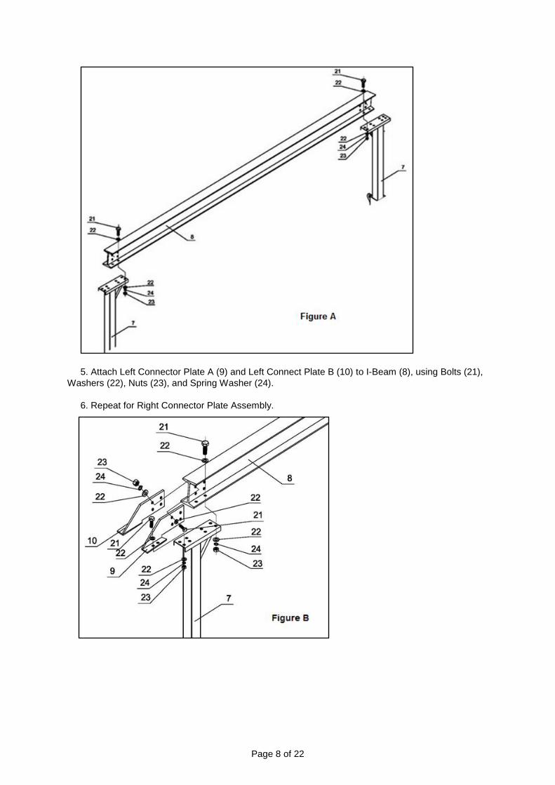
Attaching Posts and Connector Plate A & B to I-Beam
(21) Bolt M12 x 35 (22) Washer 12 (23) Nut M12 (24) Spring Washer 12
1. Lay I-Beam (8) on the ground. Lay left and right Post Assemblies on the ground.
2. Attach Left Post Insert (7) to I-Beam (8), using Bolts (21), Washers (22), Nuts (23) and Spring
Washer (24). Each Bolt (21) needs 2 washers (22) to attach.
3. Tighten connections securely
4. Repeat for Right Post Assembly.
Page 8 of 22
5. Attach Left Connector Plate A (9) and Left Connect Plate B (10) to I-Beam (8), using Bolts (21),
Washers (22), Nuts (23), and Spring Washer (24).
6. Repeat for Right Connector Plate Assembly.
Page 9 of 22
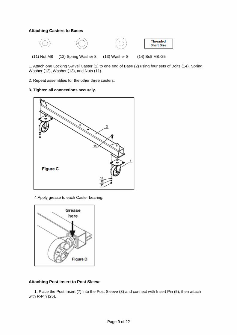
Attaching Casters to Bases
(11) Nut M8 (12) Spring Washer 8 (13) Washer 8 (14) Bolt M8×25
1. Attach one Locking Swivel Caster (1) to one end of Base (2) using four sets of Bolts (14), Spring
Washer (12), Washer (13), and Nuts (11).
2. Repeat assemblies for the other three casters.
3. Tighten all connections securely.
4.Apply grease to each Caster bearing.
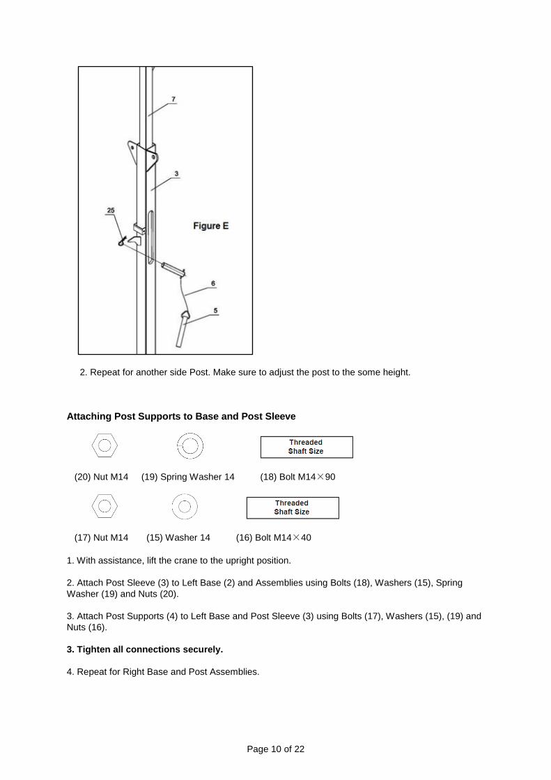
Attaching Post Insert to Post Sleeve
1. Place the Post Insert (7) into the Post Sleeve (3) and connect with Insert Pin (5), then attach
with R-Pin (25).
Page 10 of 22
2. Repeat for another side Post. Make sure to adjust the post to the some height.
Attaching Post Supports to Base and Post Sleeve
(20) Nut M14 (19) Spring Washer 14 (18) Bolt M14×90
(17) Nut M14 (15) Washer 14 (16) Bolt M14×40
1. With assistance, lift the crane to the upright position.
2. Attach Post Sleeve (3) to Left Base (2) and Assemblies using Bolts (18), Washers (15), Spring
Washer (19) and Nuts (20).
3. Attach Post Supports (4) to Left Base and Post Sleeve (3) using Bolts (17), Washers (15), (19) and
Nuts (16).
3. Tighten all connections securely.
4. Repeat for Right Base and Post Assemblies.
Page 11 of 22
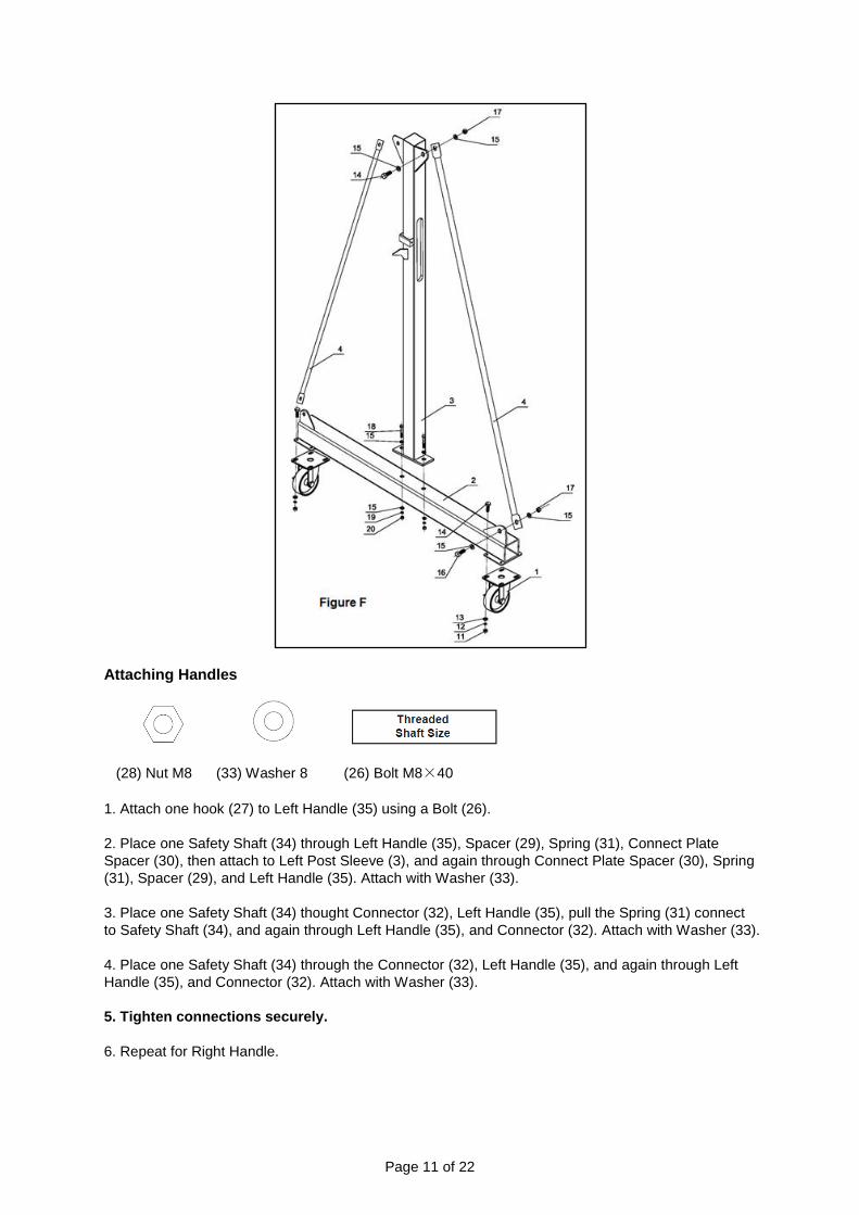
Attaching Handles
(28) Nut M8 (33) Washer 8 (26) Bolt M8×40
1. Attach one hook (27) to Left Handle (35) using a Bolt (26).
2. Place one Safety Shaft (34) through Left Handle (35), Spacer (29), Spring (31), Connect Plate
Spacer (30), then attach to Left Post Sleeve (3), and again through Connect Plate Spacer (30), Spring
(31), Spacer (29), and Left Handle (35). Attach with Washer (33).
3. Place one Safety Shaft (34) thought Connector (32), Left Handle (35), pull the Spring (31) connect
to Safety Shaft (34), and again through Left Handle (35), and Connector (32). Attach with Washer (33).
4. Place one Safety Shaft (34) through the Connector (32), Left Handle (35), and again through Left
Handle (35), and Connector (32). Attach with Washer (33).
5. Tighten connections securely.
6. Repeat for Right Handle.
Page 12 of 22
Before Each Use
⚠WARNING
TO PREVENT SERIOUS INJURY AND DEATH: The use of cranes is subject to certain hazards
that cannot be met by mechanical means, but only by the exercise of intelligence, care, common
sense, and experience in anticipating the motions that will occur as a result of operating the
controls.
Wear ANSI Z87.1 compliant safety goggles, hard hat, heavy-duty work gloves, and steel-toed work
boots during operation.
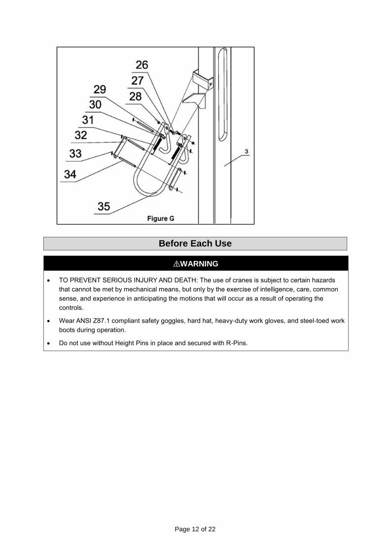
Do not use without Height Pins in place and secured with R-Pins.
Page 13 of 22
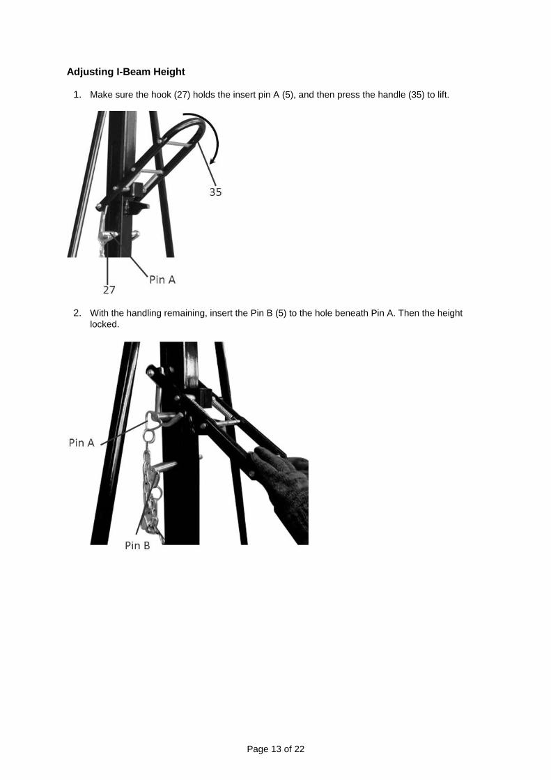
Adjusting I-Beam Height
1. Make sure the hook (27) holds the insert pin A (5), and then press the handle (35) to lift.
2. With the handling remaining, insert the Pin B (5) to the hole beneath Pin A. Then the height
locked.
Page 14 of 22
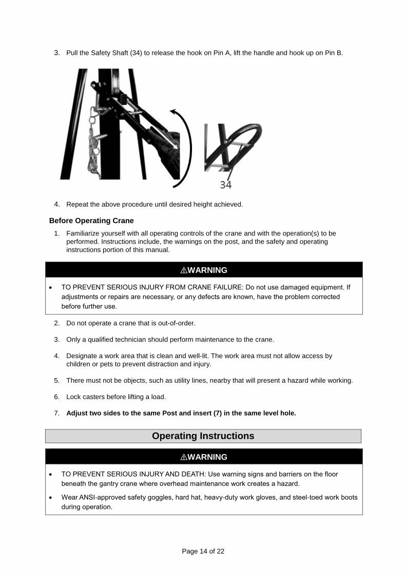
3. Pull the Safety Shaft (34) to release the hook on Pin A, lift the handle and hook up on Pin B.
4. Repeat the above procedure until desired height achieved.
Before Operating Crane
1. Familiarize yourself with all operating controls of the crane and with the operation(s) to be
performed. Instructions include, the warnings on the post, and the safety and operating
instructions portion of this manual.
⚠WARNING
TO PREVENT SERIOUS INJURY FROM CRANE FAILURE: Do not use damaged equipment. If
adjustments or repairs are necessary, or any defects are known, have the problem corrected
before further use.
2. Do not operate a crane that is out-of-order.
3. Only a qualified technician should perform maintenance to the crane.
4. Designate a work area that is clean and well-lit. The work area must not allow access by
children or pets to prevent distraction and injury.
5. There must not be objects, such as utility lines, nearby that will present a hazard while working.
6. Lock casters before lifting a load.
7. Adjust two sides to the same Post and insert (7) in the same level hole.
Operating Instructions
⚠WARNING
TO PREVENT SERIOUS INJURY AND DEATH: Use warning signs and barriers on the floor
beneath the gantry crane where overhead maintenance work creates a hazard.
Wear ANSI-approved safety goggles, hard hat, heavy-duty work gloves, and steel-toed work boots
during operation.

Page 15 of 22
Always have a least 2 people operating crane at any time.
Operate on a hard, level surface.
Do not operate crane if the beam is not level.
Do not use to lift people or animals.
Keep persons and property clear from under the load.
Do not allow the load to swing or roll against the support members.
Applying the Load
1. Attach the load to the load hook securely by properly rated, suitable means, such as chains,
shackles, hooks, lifting slings, etc. Load must be attached to prevent accidental disconnection.
2. Properly seat the sling or other device in the base (bowl or saddle) of the hook (Figure L). Do
not allow the hook hitch to support any part of the load.
3. Do not apply the load to the point of the hook (Figure L).
4. Do not operate the crane unless it is centered over the load.
5. Do not pick up a load in excess of the rated load appearing on the crane or load block, except
during properly authorized tests. Do not use a crane overload limiting device to measure the
maximum load to be lifted.
6. Give specific attention to load balancing and hitching or slinging to prevent load slipping.
Moving the Load
1. Do not engage in any activity which will divert the operator’s attention while operating the crane.
2. Respond to signals from a designated people only.
3. Do not lift or lower a load with the crane until the operator and all other people are clear of the
load.
4. Make sure the load and crane will clear all obstacles before moving or rotating the load.
5. Do not lift a load more than a few inches until it is well balanced in the sling or lifting device.
6. Each time a load approaching rated capacity is handled, check crane brake action by lifting the
load just clear of supports and continuing only after verifying that the brake system is operating
properly.
⚠WARNING
Do not use to lift people or animals.
Page 16 of 22
Keep persons and property clear from under the load.
Do not allow the load to swing or roll against the support members.
7. Avoid swinging the load or load hook when moving the crane.
8. Avoid contact between trolleys and between trolleys and stops.
9. Do not use the upper (or lower, if provided) limit devices as a normal means of stopping the
crane. These are emergency devices only
10. Do not move the crane while loaded.
Parking the Load
1. Do not leave a suspended load unattended unless specific precautions have been instituted and
are in place.
2. Position the load block above head level for storage when the crane is not in use.
3. Exercise care when removing a sling from under a landed and blocked load.
After Each Use
1. Lock the crane casters, adjust the crane at the lowest height, and insert Height Pins and secure
in place with R-Pins.
2. Position the load block above head level for storage when the crane is not in use.
3. Move the crane to a location where it will create the least interference with other cranes or
objects.
4. Keep the crane in a clean, well-lit, and safe storage area. To prevent injury, do not allow access
by children or pets.
Maintenance
⚠WARNING
TO PREVENT SERIOUS INJURY FROM CRANE FAILURE: Do not use damaged equipment. If
any defect or damage is noted, have the problem corrected before further use.
Repair or replacement of crane components must be performed only by a qualified technician
using only identical replacement parts with the same rating.
Page 17 of 22
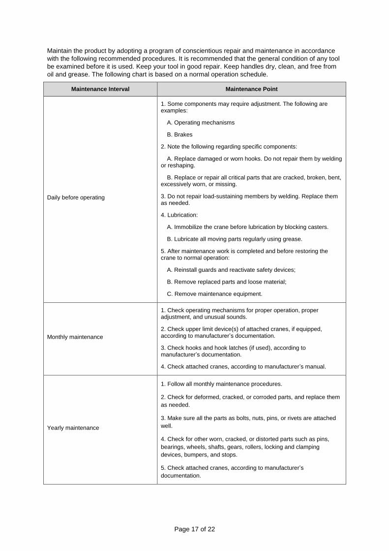
Maintain the product by adopting a program of conscientious repair and maintenance in accordance
with the following recommended procedures. It is recommended that the general condition of any tool
be examined before it is used. Keep your tool in good repair. Keep handles dry, clean, and free from
oil and grease. The following chart is based on a normal operation schedule.
Maintenance Interval Maintenance Point
Daily before operating
1. Some components may require adjustment. The following are examples:
A. Operating mechanisms
B. Brakes
2. Note the following regarding specific components:
A. Replace damaged or worn hooks. Do not repair them by welding or reshaping.
B. Replace or repair all critical parts that are cracked, broken, bent, excessively worn, or missing.
3. Do not repair load-sustaining members by welding. Replace them as needed.
4. Lubrication:
A. Immobilize the crane before lubrication by blocking casters.
B. Lubricate all moving parts regularly using grease.
5. After maintenance work is completed and before restoring the crane to normal operation:
A. Reinstall guards and reactivate safety devices;
B. Remove replaced parts and loose material;
C. Remove maintenance equipment.
Monthly maintenance
1. Check operating mechanisms for proper operation, proper adjustment, and unusual sounds.
2. Check upper limit device(s) of attached cranes, if equipped, according to manufacturer’s documentation.
3. Check hooks and hook latches (if used), according to manufacturer’s documentation.
4. Check attached cranes, according to manufacturer’s manual.
Yearly maintenance
1. Follow all monthly maintenance procedures.
2. Check for deformed, cracked, or corroded parts, and replace them
as needed.
3. Make sure all the parts as bolts, nuts, pins, or rivets are attached
well.
4. Check for other worn, cracked, or distorted parts such as pins,
bearings, wheels, shafts, gears, rollers, locking and clamping
devices, bumpers, and stops.
5. Check attached cranes, according to manufacturer’s
documentation.
Page 18 of 22
Troubleshooting
⚠WARNING
TO PREVENT SERIOUS INJURY FROM CRANE FAILURE: Do not use damaged equipment. If
any defect or damage is noted, have the problem corrected before further use.
Repair or replacement of crane components must be performed only by a qualified technician
using only identical replacement parts with the same rating.
Use the table below to troubleshoot problems before contacting service personnel or your local
dealer. If the problem continues after troubleshooting, call your local dealer for assistance.
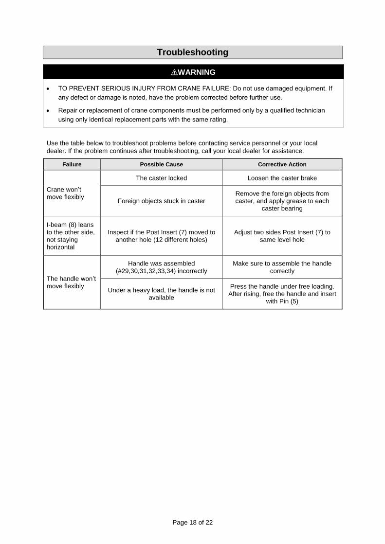
Failure Possible Cause Corrective Action
Crane won’t move flexibly
The caster locked Loosen the caster brake
Foreign objects stuck in caster Remove the foreign objects from caster, and apply grease to each
caster bearing
I-beam (8) leans to the other side, not staying horizontal
Inspect if the Post Insert (7) moved to another hole (12 different holes)
Adjust two sides Post Insert (7) to same level hole
The handle won’t move flexibly
Handle was assembled (#29,30,31,32,33,34) incorrectly
Make sure to assemble the handle correctly
Under a heavy load, the handle is not available
Press the handle under free loading. After rising, free the handle and insert
with Pin (5)
Page 19 of 22
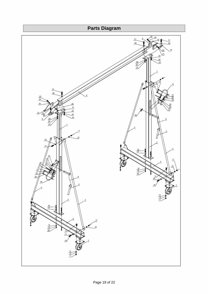
Parts Diagram

Page 20 of 22
Parts List
Part Number Part Description Qty. Remark
1 4'' Locking Swivel Caster 4
2 Base 2
3 Post Sleeve 2
4 Post Support 4
5 Inserted Pin 4
6 Cable 2
7 Post Insert 2
8 I-Beam 1
9 Connector Plate A 2
10 Connector Plate B 2
11 Nut 16 M8
12 Spring Washer 16 8
13 Washer 16 8
14 Bolt 16 M8×25
15 Washer 24 14
16 Bolt 8 M14×40
17 Nut 8 M14
18 Bolt 4 M14×90
19 Spring Washer 4 14
20 Nut 4 M14
21 Bolt 24 M12×35
22 Washer 48 12
23 Nut 24 M12
24 Spring Washer 24 12
25 R-Pin 4
26 Bolt 4 M8×40
27 Hook 4
28 Nut 4 M8
29 Spacer 4
30 Connect Plate Spacer 4
31 Spring 4
32 Connector 4
33 Washer 12 8
34 Safety Shaft 6
35 Handle 2
Replacement Parts
For replacement parts and technical questions, please call Customer Service at 1-800-222-5381.
Not all product components are available for replacement. The illustrations provided are a
convenient reference to the location and position of parts in the assembly sequence.
When ordering parts, the following information will be required: item description, item model
number, item serial number/item lot date code, and the replacement part reference number.
The distributor reserves the rights to make design changes and improvements to product lines
and manuals without notice.

Page 21 of 22
Limited Warranty
Northern Tool and Equipment Company, Inc. ("We'' or "Us'') warrants to the original purchaser only
("You'' or "Your") that the Strongway product purchased will be free from material defects in both
materials and workmanship, normal wear and tear excepted, for a period of one year from date of
purchase. The foregoing warranty is valid only if the installation and use of the product is strictly in
accordance with product instructions. There are no other warranties, express or implied, including the
warranty of merchantability or fitness for a particular purpose. If the product does not comply with this
limited warranty, Your sole and exclusive remedy is that We will, at our sole option and within a
commercially reasonable time, either replace the product or product component without charge to You
or refund the purchase price (less shipping). This limited warranty is not transferable.
Limitations on the Warranty
This limited warranty does not cover: (a) normal wear and tear; (b) damage through abuse, neglect,
misuse, or as a result of any accident or in any other manner; (c) damage from misapplication,
overloading, or improper installation; (d) improper maintenance and repair; and (e) product alteration
in any manner by anyone other than Us, with the sole exception of alterations made pursuant to
product instructions and in a workmanlike manner.
Obligations of Purchaser
You must retain Your product purchase receipt to verify date of purchase and that You are the original
purchaser. To make a warranty claim, contact Us at 1-800-222-5381, identify the product by make
and model number, and follow the claim instructions that will be provided. The product and the
purchase receipt must be provided to Us in order to process Your warranty claim. Any returned
product that is replaced or refunded by Us becomes our property. You will be responsible for return
shipping costs or costs related to Your return visit to a retail store.
Remedy Limits
Product replacement or a refund of the purchase price is Your sole remedy under this limited warranty
or any other warranty related to the product. We shall not be liable for: service or labor charges or
damage to Your property incurred in removing or replacing the product; any damages, including,
without limitation, damages to tangible personal property or personal injury, related to Your improper
use, installation, or maintenance of the product or product component; or any indirect, incidental or
consequential damages of any kind for any reason.
Assumption of Risk
You acknowledge and agree that any use of the product for any purpose other than the specified
use(s) stated in the product instructions is at Your own risk.
Governing Law
This limited warranty gives You specific legal rights, and You also may have other rights which vary
from state to state. Some states do not allow limitations or exclusions on implied warranties or
incidental or consequential damages, so the above limitations may not apply to You. This limited
warranty is governed by the laws of the State of Minnesota, without regard to rules pertaining to
conflicts of law. The state courts located in Dakota County, Minnesota shall have exclusive jurisdiction
for any disputes relating to this warranty.

Page 22 of 22
Distributed by:
Northern Tool & Equipment Company, Inc.
Burnsville, Minnesota 55306
www.northerntool.com
Made in China