Embed Size (px)
Citation preview

100 Gb/s Serial Transmission over Copper
using Duo-binary Signaling
Timothy De Keulenaer, (Ghent University)
Ramses Pierco, (Ghent University)
Jan De Geest, (Amphenol FCI)
Joris Van Kerrebrouck (Ghent University), Timothy De Keulenaer (Ghent University)
Jan De Geest (Amphenol FCI), Ramses Pierco (Ghent University), Renato Vaernewyck (Ghent University)
Arno Vyncke (Ghent University), Michael Fogg (Amphenol FCI), Madhumita Rengarajan (Amphenol FCI)
Guy Torfs (Ghent University), Johan Bauwelinck (Ghent University)

SPEAKERS
Timothy De KeulenaerPostdoctoral researcher, Ghent University
www.intec.ugent.be/design/bifast
Ramses PiercoPostdoctoral researcher, Ghent University
www.intec.ugent.be/design/bifast
Introduction
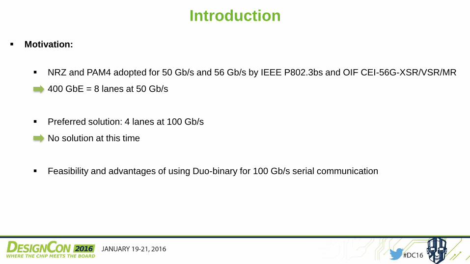
Motivation:
NRZ and PAM4 adopted for 50 Gb/s and 56 Gb/s by IEEE P802.3bs and OIF CEI-56G-XSR/VSR/MR
400 GbE = 8 lanes at 50 Gb/s
Preferred solution: 4 lanes at 100 Gb/s
No solution at this time
Feasibility and advantages of using Duo-binary for 100 Gb/s serial communication

Introduction
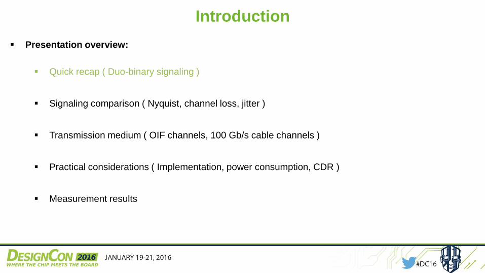
Presentation overview:
Quick recap ( Duo-binary signaling )
Signaling comparison ( Nyquist, channel loss, jitter )
Transmission medium ( OIF channels, 100 Gb/s cable channels )
Practical considerations ( Implementation, power consumption, CDR )
Measurement results
Introduction
Presentation overview:
Quick recap ( Duo-binary signaling )
Signaling comparison ( Nyquist, channel loss, jitter )
Transmission medium ( OIF channels, 100 Gb/s cable channels )
Practical considerations ( Implementation, power consumption, CDR )
Measurement results

Quick recap: Duo-binary signaling
Duo-binary VS NRZ:
One Duo-binary symbol =
combination of current and
previous NRZ bit (1 + z-1)
Symbols: +1 (1,1), 0 (0,1 or
1,0) and -1 (0,0)
Duo-binary symbol rate =
NRZ bit rate
+1 never followed by -1
(due to 1 + z-1)
Bandwidth is reduced

Quick recap: Duo-binary signaling
Duo-binary creation:
Create Duo-binary at the
transmitter
Create Duo-binary at the
receiver by means of the FFE
shaping + channel characteristic
(NRZ transmitter)
Easy transmitter
Part of the channel loss doesn’t
need to be compensated ( is
used to create Duo-binary )

Introduction
Presentation overview:
Quick recap ( Duo-binary signaling )
Signaling comparison ( Nyquist, channel loss, jitter )
Transmission medium ( OIF channels, 100 Gb/s cable channels )
Practical considerations ( Implementation, power consumption, CDR )
Measurement results

Signaling comparison: Nyquist frequency
Nyquist frequency:
Used to compare the bandwidth
needed by different modulations
Theoretically: Minimum frequency
for which no ISI occurs
NRZ 1/(2Ts)
PAM4 1/(4Ts)
Duo-binary ?

Signaling comparison: Nyquist frequency
Duo-binary Nyquist frequency:
1/2Ts frequency needed for no
ISI but can be infinitely small
Second largest frequency in
signal = 1/(3Ts)
Eye height = ¾ of Nyquist
frequency signal swing

Signaling comparison: Channel loss
Channel loss at Nyquist determines eye height at the Rx
Lower Nyquist frequency
From a certain amount of channel loss the eye-height at
the receiver will be bigger
PAM4 has 9.54dB penalty compared to NRZ (eye height
divided by Nyquist frequency amplitude)
DB has 2.5dB penalty compared to NRZ
Possible to calculate for a certain data rate the amount of
channel loss for which: DB is better than NRZ, PAM4 is
better than NRZ, PAM4 is better than DB
Data rate 50 Gb/s 100 Gb/s
NRZ DB 0.30
dB/GHz
0.15
dB/GHz
NRZ PAM4 0.76
dB/GHz
0.38
dB/GHz
DB PAM4 1.69
dB/GHz
0.84
dB/GHz

Signaling comparison: Channel loss
Channel loss at Nyquist method
only correct if Duo-binary created at
transmitter
Eye-height calculation at
receiver based on equalization
transfer function being the
inverse of channel transfer
function.
Not true if Duo-binary created
with equalizer and channel

Signaling comparison: Channel loss
Real-life system: Eye-height limited by possible amplitude at transmitter
Calculate ideal channel response up to the Tx output (equalizer at the Tx) for NRZ, DB and PAM4 for
a certain amount of channel loss and data-rate DC - value represents eye-height at the receiver

Signaling comparison: Channel loss and CPSD
Previous method correct, but:
No easy calculation formulas
Nyquist of PAM4 based on Nyquist pulses ↔ real-life
consists of rectangular pulses
Equalization up to higher frequencies needed for no ISI
in case of PAM4 (Duo-binary equalized up to 1/2Ts)
Cumulative power spectral density (CPSD) determines
amount of ISI
Higher CPSD lower ISI ( 1/4Ts = 81.5%CPSD )

Signaling comparison: Channel loss and CPSD
Ideal modulation format:
Determined by data rate and
channel loss
Determined by CPSD
percentage needed for PAM4
(depends on desired eye width)
50 Gb/s:
23.1 dB @ 12.5 GHz
46.2 dB @ 25 GHz

Signaling comparison: Jitter
Jitter tolerance, dependent on threshold
level
Largest available eye width
DB: 1 Ts (eye height penalty: 41.4%)
PAM4: 1.33 Ts (eye height penalty: 50%)
Threshold midway eye height
DB: 0.67 Ts
PAM4: 1.07 Ts

Introduction
Presentation overview:
Quick recap ( Duo-binary signaling )
Signaling comparison ( Nyquist, channel loss, jitter )
Transmission medium ( OIF channels, 100 Gb/s cable channels )
Practical considerations ( Implementation, power consumption, CDR )
Measurement results

Transmission medium: OIF 56G channels
Ideal modulation format:
For 56 Gb/s: DB will have
largest eye for VSR and MR
For 100 Gb/s: DB will have
largest eye for XSR and VSR,
for MR dependent on channel
and wanted CPSD for PAM4

Transmission medium: Cable channels for 100 Gb/s
Cable channels:
Lengths from 2m onwards
corresponds to OIF MR
For 56 Gb/s: DB will always
result in larger eye height
For 100 Gb/s: Dependent on
PAM4 CPSD, DB or PAM4
will have larger eye height.

Transmission medium: Cable channels for 100 Gb/s
Cable channels:
Suppose 1Vpp at
transmitter
Eye height and
SNR at receiver?
Eye height(mV)| SNR (dB)
ExaMax®30 AWG1m
ExaMax®30 AWG2m
ExaMax®30 AWG3m
QSFP30 AWG2m
QSFP26 AWG3m
NRZ 70.16| 35.8
4.85
| 12.6
<1
| <0
3.75
| 10.4
2.02
| 4.98
Duo-binary 169.5| 48.2
22.49
| 30.7
2.33
| 11.0
18.18
| 28.8
10.85
| 24.4
PAM4, 81.5% 88.08| 43.8
23.10
| 32.2
6.10
| 20.6
20.29
| 31.0
14.89
| 28.4
PAM4, 85% 77.93| 42.3
18.07
| 29.6
4.22
| 17.0
15.69
| 28.4
11.49
| 25.5
PAM4, 90% 61.65| 39.7
11.30
| 24.9
2.09
| 10.3
9.59
| 23.5
6.47
| 20.1
Transmission medium: Cable channels for 100 Gb/s
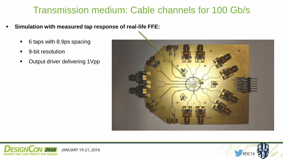
Simulation with measured tap response of real-life FFE:
6 taps with 8.9ps spacing
9-bit resolution
Output driver delivering 1Vpp

Transmission medium: Cable channels for 100 Gb/s
Cable channels:
Real-life equalizer
Penalty compared
to theory
Eye height(mV)| Penalty
ExaMax®30 AWG1m
ExaMax®30 AWG2m
ExaMax®30 AWG3m
QSFP30 AWG2m
QSFP26 AWG3m
Duo-binary 120| 29.2 %
10
| 55.5 %
<1 9
| 50.5%
<1
PAM4, 81.5% 52| 41.0 %
5
| 78.4 %
<1 <1 <1
PAM4, 85% 54| 30.7 %
9
| 50.2 %
<1 <1 <1
PAM4, 90% 40|35.1 %
6
| 46.9 %
<1 5
| 47.9 %
<1

Transmission medium: ExaMax® 30 AWG 2m
Duo-binary eye 100 Gb/s PAM4 eye 100 Gb/s
Equalized up to 25 GHz
PAM4 eye 100 Gb/s
Equalized up to 27.3 GHz
(CPSD = 85%)

Transmission medium: Cable channels for 100 Gb/s
Why is PAM4 so much worse with real-life FFE
than in theory?
The use of rectangular pulses in real-life
Insufficient to equalize up to the Nyquist
frequency of PAM4 for high-loss channels
ISI reduces eye height
Limited dynamic range (number of bits to set tap
value) seems to affect PAM4 more than DB
(ripple in eye height plot)

Transmission medium: Cable channels for 100 Gb/s
What about suck-outs?
Simulation with ideal equalizer (rule out effect of limited number of bits), equalized up to 1/2Ts (no ISI)
Variation of suck-out frequency and width
QSFP, 26AWG, 3m
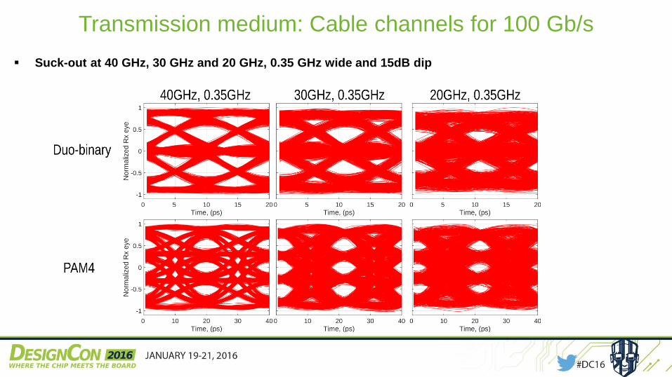
Transmission medium: Cable channels for 100 Gb/s
Suck-out at 40 GHz, 30 GHz and 20 GHz, 0.35 GHz wide and 15dB dip

Transmission medium: Cable channels for 100 Gb/s
Suck-out at 40 GHz, 30 GHz and 20 GHz, 0.7 GHz wide and 15dB dip

Transmission medium: Cable channels for 100 Gb/s
Suck-out at 40 GHz, 30 GHz and 20 GHz, 1.4 GHz wide and 15dB dip

Transmission medium: Cable channels for 100 Gb/s
What about jitter?
PAM4 equalized
up to 1/2Ts (min.
effect of ISI)
Channel loss 0.5 dB/GHz 0.75 dB/GHz 1 dB/GHz 1.25dB/GHz
DB: eye-width
/ penalty
8.2 ps
/ 18%
7.85 ps
/ 21.5%
5.7 ps
/ 43%
4.5 ps
/ 55%
PAM4: eye-width
/penalty
9.15 ps
/ 31.4%
8.85 ps
/ 33.6%
4.7 ps
/ 64.7%
/
/ 100%

Introduction
Presentation overview:
Quick recap ( Duo-binary signaling )
Signaling comparison ( Nyquist, channel loss, jitter )
Transmission medium ( OIF channels, 100 Gb/s cable channels )
Practical considerations ( Implementation, power consumption, CDR )
Measurement results

Practical considerations: Implementation
Transmitter and receiver topology:
NRZ transmitter is sufficient (possibly with equalizer)
Pre-coder needed at transmitter: easy implementation by means of flip-flop and XOR
At the receiver: two slicers followed by XOR

Practical considerations: Power consumption
No easy comparison:
Chipset in same technology for all modulation formats signaling across same channel
= only fair comparison
In previous work this led to lower power consumption for Duo-binary*
First estimates of our new chipset = 1W for one 100 Gb/s link (Tx, Rx+CDR and SERDES)
(* J. Lee, M.-S. Chen, H.-D. Wang, IEEE JSSC, vol.43, no.9, pp. 2120-2133, Sept. 2008)
Practical considerations: CDR
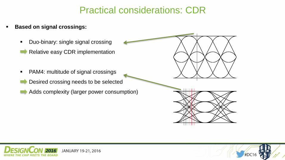
Based on signal crossings:
Duo-binary: single signal crossing
Relative easy CDR implementation
PAM4: multitude of signal crossings
Desired crossing needs to be selected
Adds complexity (larger power consumption)

Introduction
Presentation overview:
Quick recap ( Duo-binary signaling )
Signaling comparison ( Nyquist, channel loss, jitter )
Transmission medium ( OIF channels, 100 Gb/s cable channels )
Practical considerations ( Implementation, power consumption, CDR )
Measurement results

Measurement results
Test setups:
Amphenol FCI ExaMAX® backplane daughter cards – 56 Gb/s
Twin-ax cable – 56 Gb/s
Connectorized test boards – 100 Gb/s
Twin-ax cable – 100 Gb/s

Amphenol FCI ExaMAX® backplane setup:
Serializer + Duo-binary transmitter Duo-binary receiver + De-serializerExaMAX ® backplane channel
Measurement results: Amphenol FCI ExaMAX® backplane
Pattern generator
1 x 56 Gb/s
BERT1 x 14 Gb/s

32 dB @ 28 GHz – BER < 1e-12
Measurement results: 56 Gb/s transmission
Measured Duo-binary transmission:
Backplane channels from 13” up to 20”
56 Gb/s – 13” 56 Gb/s – 20”
43 dB @ 28 GHz – BER < 1e-12

Cable cards – Duo-binary over 26AWG Twin-Ax setup:
Specific card for each length (0.5m, 1.5m, 3m, 5m)
Serializer + Duo-binary transmitter Duo-binary receiver + De-serializer
Measurement results: Twin-ax cable 56 Gb/s
FPGA4 x 14 Gb/s
BERT1 x 14 Gb/s

Measurement results: Twin-ax cable 56 Gb/s
Measured Duo-binary transmission:
56 Gb/s – 5m ~38dB @ 28G BER < 1e-12 (error free)

Measurement results: Connectorized test boards
Test setup:
100 Gb/s Duo-binary setup
Duo-binary receiver + De-serializer Serializer + Duo-binary transmitterTest channel
Pattern generator
4 x 25 Gb/s
BERT1 x 25 Gb/s

Measured 100 Gb/s Duo-binary eye
Measurement results: 100 Gb/s transmission
Measured Duo-binary transmission:
Initial channel for verification
Channel loss ≈ 0.3 dB/GHz
BER < 1e-12 (error free)

Cable cards – Duo-binary over 26AWG Twin-Ax setup:
Specific card for each length (0.5m, 1.5m, 3m, 5m)
Serializer + Duo-binary transmitter Duo-binary receiver + De-serializer
Measurement results: Twin-ax cable 100 Gb/s
FPGA4 x 25 Gb/s
BERT1 x 25 Gb/s

Measurement results: Twin-ax cable 100 Gb/s
Measured Duo-binary transmission:
100 Gb/s – 1.5m ~35dB @ 50G BER < 1e-12 (error free)

Conclusions
Duo-binary strongpoints:
Outperforms competition with real-life equalizer
High tolerance to jitter and suck-outs
Limited implementation complexity, low power consumption
Measurement results:
Backplane channel: 56 Gb/s up to 20” error free (no FEC, 43dB @ 28GHz)
Twin-ax cable (26AWG):
56 Gb/s up to 5m error free (no FEC), 8m feasible with FEC
100 Gb/s up to 1.5m error free (no FEC), 3m feasible with FEC
44

MORE INFORMATION
www.intec.ugent.be/design/bifast
Visit us at the booth of
Amphenol FCI 533

---
QUESTIONS?
Thank you!