Embed Size (px)
Citation preview
- 1 -
31. Internationales Wiener Motorensymposium 2010
Prof. Dr.-Ing. Mario Theissen, Dipl.-Ing. Markus Duesmann, Dipl.-Ing. Jan Hartmann, Dipl.-Ing. Matthias Klietz, Dipl.-Ing. Ulrich Schulz
BMW Group, Munich
10 Years of BMW F1 Engines
Abstract
BMW engines gave the company a presence in Formula One from 2000 to 2009. The overall project can be broken down into a preparatory phase, its years as an engine supplier to the Williams team, and a period competing under the banner of its own BMW Sauber F1 Team. The conception, design and deployment of the engines were defined by the Formula One regulations, which were subject to change virtually every year. Reducing costs was the principal aim of these revisions. Development expenditure was scaled down gradually as a result of the technical restrictions imposed on the teams and finally through homologation and a freeze on development. Engine build costs were limited by the increased mileage required of each engine and the restrictions on testing. A lower number of engines were therefore required for each season. A second aim, reduced engine output, was achieved with the switch from 3.0-litre V10 engines to 2.4-litre V8s for the 2006 season. In the early years of its involvement in F1, BMW developed and built a new engine for each season amid a high-pressure competitive environment. This process saw rapid improvements made in engine output and weight, and the BMW powerplant soon attained benchmark status in F1. In recent years, development work focused on raising mileage capability and reliability without changing the engine concept itself. The P86/9 of the 2009 season achieved the same engine output, despite a 20% reduction in displacement, of the E41/4 introduced at the beginning of the 2000 season. Its mileage capability, meanwhile, increased five-fold to more than 2,000 km over the same period. The various engine generations and their key design features are detailed, as are the equipment and expertise accumulated as part of the project.
- 2 -
31. Internationales Wiener Motorensymposium 2010
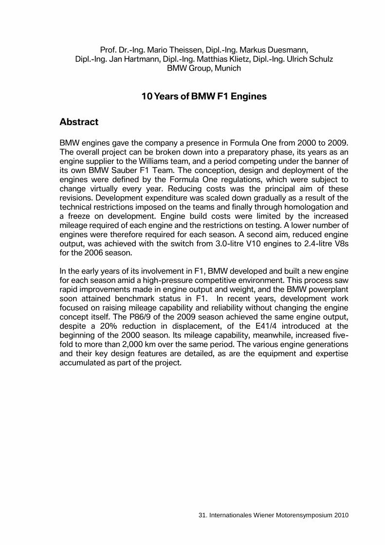
1. Project Overview The involvement of BMW in Formula One from 2000 can be broken down into three phases: the preparation period, six years as an engine partner for Williams, and four years with its own BMW Sauber F1 Team. Although the focus and scope of the project changed significantly through the various transitions, one thing has remained the same throughout: the engine was always developed, built and deployed from Munich.
Fig. 1: Phases of the BMW Formula One project
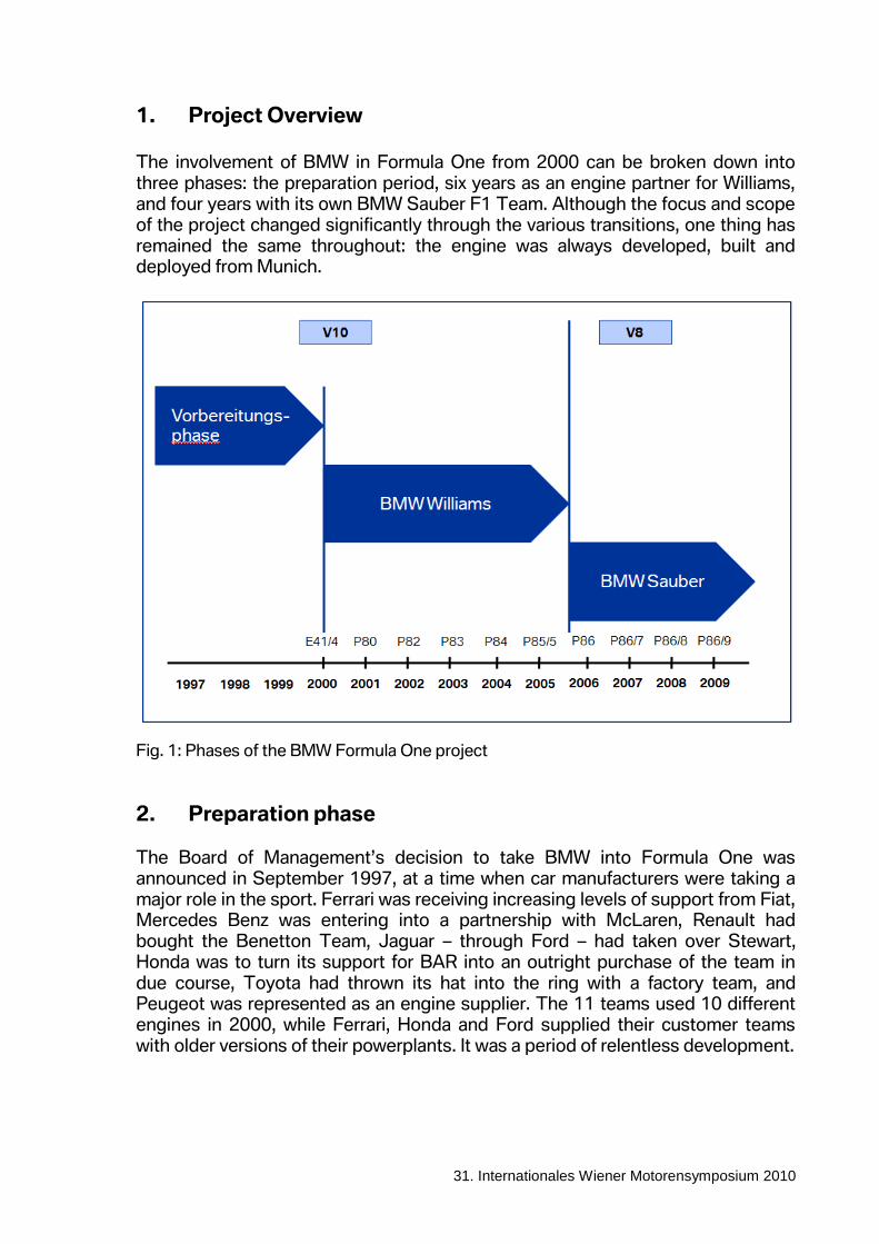
2. Preparation phase The Board of Management’s decision to take BMW into Formula One was announced in September 1997, at a time when car manufacturers were taking a major role in the sport. Ferrari was receiving increasing levels of support from Fiat, Mercedes Benz was entering into a partnership with McLaren, Renault had bought the Benetton Team, Jaguar – through Ford – had taken over Stewart, Honda was to turn its support for BAR into an outright purchase of the team in due course, Toyota had thrown its hat into the ring with a factory team, and Peugeot was represented as an engine supplier. The 11 teams used 10 different engines in 2000, while Ferrari, Honda and Ford supplied their customer teams with older versions of their powerplants. It was a period of relentless development.
- 3 -
31. Internationales Wiener Motorensymposium 2010
Engine Teams
BMW E41/4 V10 72° Williams
Ferrari 049 B-C V10 90° Ferrari
Ferrari 048/04 A V10 80° Sauber
Ford Cosworth CR2 V10 72° Jaguar
Ford Cosworth Zetec-R V10 72° Minardi
Honda RA 000 E V10 80° BAR
Honda Mugen MF-301 V10 72° Jordan
Mercedes Ilmor F 110J V10 72° Mc Laren
Peugeot A20 Evo 4 V10 72° Prost
Supertec FB 02 V10 71° Benetton
Arrows
Fig. 2: Engine variants in 2000
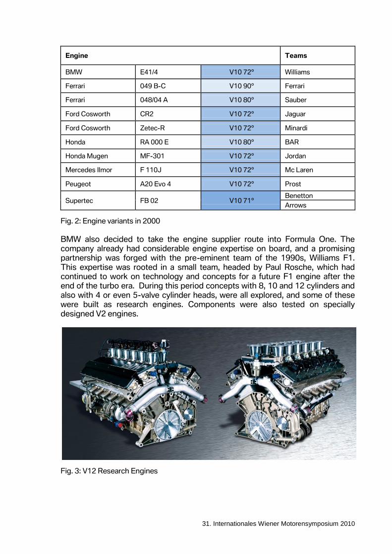
BMW also decided to take the engine supplier route into Formula One. The company already had considerable engine expertise on board, and a promising partnership was forged with the pre-eminent team of the 1990s, Williams F1. This expertise was rooted in a small team, headed by Paul Rosche, which had continued to work on technology and concepts for a future F1 engine after the end of the turbo era. During this period concepts with 8, 10 and 12 cylinders and also with 4 or even 5-valve cylinder heads, were all explored, and some of these were built as research engines. Components were also tested on specially designed V2 engines.
Fig. 3: V12 Research Engines
- 4 -
31. Internationales Wiener Motorensymposium 2010
The go-ahead for the F1 project in 1997 sparked a race against time in several areas. The team had to be expanded from approximately 25 employees to more than 200, an F1 factory had to be built and the engine for the 2000 season had to be developed. In this phase the course was set for an intensive transfer of technology between F1 and series production:
Engine management hardware and software were developed and manufactured in an in-house electronics department containing a prototype production facility. The KERS system was also created here. Today the department focuses on hybrid concepts for series production vehicles.
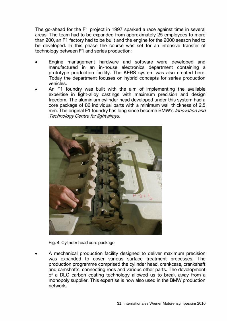
An F1 foundry was built with the aim of implementing the available expertise in light-alloy castings with maximum precision and design freedom. The aluminium cylinder head developed under this system had a core package of 86 individual parts with a minimum wall thickness of 2.5 mm. The original F1 foundry has long since become BMW’s Innovation and Technology Centre for light alloys.
Fig. 4: Cylinder head core package
A mechanical production facility designed to deliver maximum precision was expanded to cover various surface treatment processes. The production programme comprised the cylinder head, crankcase, crankshaft and camshafts, connecting rods and various other parts. The development of a DLC carbon coating technology allowed us to break away from a monopoly supplier. This expertise is now also used in the BMW production network.
- 5 -
31. Internationales Wiener Motorensymposium 2010
The extensive advances made in-house gave a sustained boost to production engine technology and were also a key advantage for the F1 project itself:
Development engineers and production specialists within the team worked closely to fully exploit the design boundaries.
Analysis of the full production process and removing transport requirements between the individual working stages allowed us to improve quality, and reduce lead times and costs.
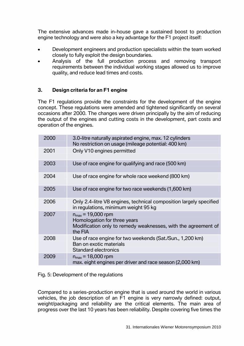
3. Design criteria for an F1 engine The F1 regulations provide the constraints for the development of the engine concept. These regulations were amended and tightened significantly on several occasions after 2000. The changes were driven principally by the aim of reducing the output of the engines and cutting costs in the development, part costs and operation of the engines.
2000 3.0-litre naturally aspirated engine, max. 12 cylinders No restriction on usage (mileage potential: 400 km)
2001 Only V10 engines permitted
2003 Use of race engine for qualifying and race (500 km)
2004 Use of race engine for whole race weekend (800 km)
2005 Use of race engine for two race weekends (1,600 km)
2006 Only 2.4-litre V8 engines, technical composition largely specified in regulations, minimum weight 95 kg
2007 nmax = 19,000 rpm Homologation for three years Modification only to remedy weaknesses, with the agreement of the FIA
2008 Use of race engine for two weekends (Sat./Sun., 1,200 km) Ban on exotic materials Standard electronics
2009 nmax = 18,000 rpm max. eight engines per driver and race season (2,000 km)
Fig. 5: Development of the regulations Compared to a series-production engine that is used around the world in various vehicles, the job description of an F1 engine is very narrowly defined: output, weight/packaging and reliability are the critical elements. The main area of progress over the last 10 years has been reliability. Despite covering five times the
- 6 -
31. Internationales Wiener Motorensymposium 2010
mileage and generating a higher specific output, the failure rate of engines is now lower than that in 2000. This was achieved in the design layout, using extremely tight manufacturing tolerances, using more durable materials and surfaces, and ensuring flawless quality control for each individual part. When it comes to the connecting rod bearing, for example, the slightest fluctuation in the alloy or a minimal deviation from tolerances can make the difference between the engine covering its full mileage potential without a problem and an early failure. The switch in 2006 to a 2.4-litre V8 weighing at least 95 kg was a key moment in the development of engine output and weight.
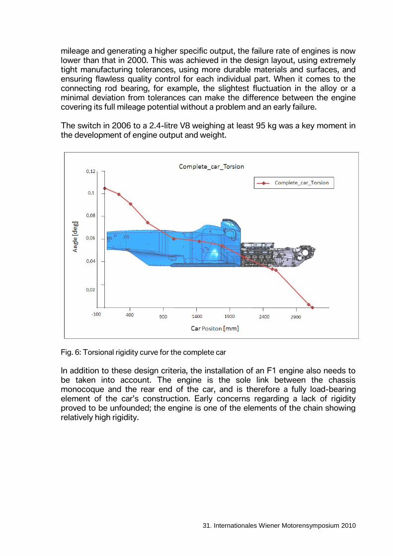
Fig. 6: Torsional rigidity curve for the complete car
In addition to these design criteria, the installation of an F1 engine also needs to be taken into account. The engine is the sole link between the chassis monocoque and the rear end of the car, and is therefore a fully load-bearing element of the car’s construction. Early concerns regarding a lack of rigidity proved to be unfounded; the engine is one of the elements of the chain showing relatively high rigidity.
- 7 -
31. Internationales Wiener Motorensymposium 2010
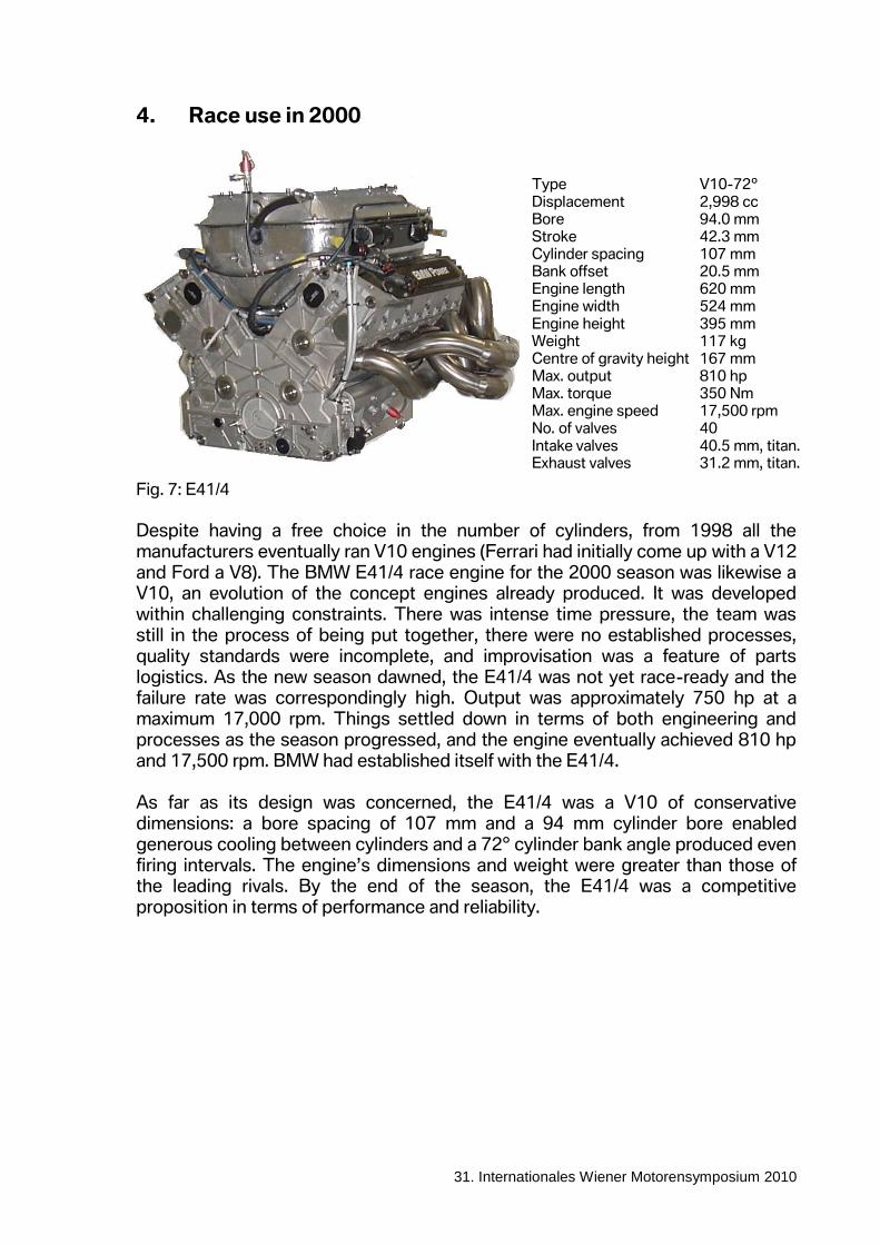
4. Race use in 2000
Fig. 7: E41/4
Despite having a free choice in the number of cylinders, from 1998 all the manufacturers eventually ran V10 engines (Ferrari had initially come up with a V12 and Ford a V8). The BMW E41/4 race engine for the 2000 season was likewise a V10, an evolution of the concept engines already produced. It was developed within challenging constraints. There was intense time pressure, the team was still in the process of being put together, there were no established processes, quality standards were incomplete, and improvisation was a feature of parts logistics. As the new season dawned, the E41/4 was not yet race-ready and the failure rate was correspondingly high. Output was approximately 750 hp at a maximum 17,000 rpm. Things settled down in terms of both engineering and processes as the season progressed, and the engine eventually achieved 810 hp and 17,500 rpm. BMW had established itself with the E41/4. As far as its design was concerned, the E41/4 was a V10 of conservative dimensions: a bore spacing of 107 mm and a 94 mm cylinder bore enabled generous cooling between cylinders and a 72° cylinder bank angle produced even firing intervals. The engine’s dimensions and weight were greater than those of the leading rivals. By the end of the season, the E41/4 was a competitive proposition in terms of performance and reliability.
Type V10-72º
Displacement 2,998 cc Bore 94.0 mm Stroke 42.3 mm Cylinder spacing 107 mm Bank offset 20.5 mm Engine length 620 mm Engine width 524 mm
Engine height 395 mm Weight 117 kg Centre of gravity height 167 mm Max. output 810 hp Max. torque 350 Nm Max. engine speed 17,500 rpm No. of valves 40
Intake valves 40.5 mm, titan. Exhaust valves 31.2 mm, titan.
- 8 -
31. Internationales Wiener Motorensymposium 2010
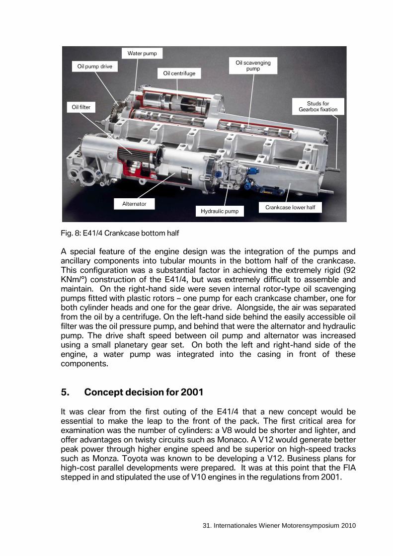
Fig. 8: E41/4 Crankcase bottom half
A special feature of the engine design was the integration of the pumps and ancillary components into tubular mounts in the bottom half of the crankcase. This configuration was a substantial factor in achieving the extremely rigid (92 KNm/°) construction of the E41/4, but was extremely difficult to assemble and maintain. On the right-hand side were seven internal rotor-type oil scavenging pumps fitted with plastic rotors – one pump for each crankcase chamber, one for both cylinder heads and one for the gear drive. Alongside, the air was separated from the oil by a centrifuge. On the left-hand side behind the easily accessible oil filter was the oil pressure pump, and behind that were the alternator and hydraulic pump. The drive shaft speed between oil pump and alternator was increased using a small planetary gear set. On both the left and right-hand side of the engine, a water pump was integrated into the casing in front of these components.
5. Concept decision for 2001 It was clear from the first outing of the E41/4 that a new concept would be essential to make the leap to the front of the pack. The first critical area for examination was the number of cylinders: a V8 would be shorter and lighter, and offer advantages on twisty circuits such as Monaco. A V12 would generate better peak power through higher engine speed and be superior on high-speed tracks such as Monza. Toyota was known to be developing a V12. Business plans for high-cost parallel developments were prepared. It was at this point that the FIA stepped in and stipulated the use of V10 engines in the regulations from 2001.
- 9 -
31. Internationales Wiener Motorensymposium 2010
Several different cylinder bank angles had already been discussed at the conception of the E41/4. The standard solution of 72° ensures even firing intervals and ensures that the engine is slim – and therefore good for the car’s aerodynamics. However, it is not ideal in terms of vibrations and, more importantly it results in a tall engine, with a correspondingly high centre of gravity. The best overall package solution was considered to be a cylinder bank angle of 90° for the P80. However, it wasn’t just its cylinder bank angle that set the P80 apart from the E41/4, this was a completely new design.
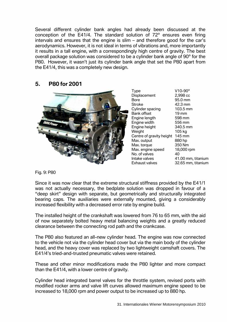
5. P80 for 2001
Fig. 9: P80
Since it was now clear that the extreme structural stiffness provided by the E41/1 was not actually necessary, the bedplate solution was dropped in favour of a “deep skirt” design with separate, but geometrically and structurally integrated bearing caps. The auxiliaries were externally mounted, giving a considerably increased flexibility with a decreased error rate by engine build. The installed height of the crankshaft was lowered from 76 to 65 mm, with the aid of now separately bolted heavy metal balancing weights and a greatly reduced clearance between the connecting rod path and the crankcase. The P80 also featured an all-new cylinder head. The engine was now connected to the vehicle not via the cylinder head cover but via the main body of the cylinder head, and the heavy cover was replaced by two lightweight camshaft covers. The E41/4’s tried-and-trusted pneumatic valves were retained. These and other minor modifications made the P80 lighter and more compact than the E41/4, with a lower centre of gravity. Cylinder head integrated barrel valves for the throttle system, revised ports with modified rocker arms and valve lift curves allowed maximum engine speed to be increased to 18,000 rpm and power output to be increased up to 880 hp.
Type V10-90º Displacement 2,998 cc Bore 95.0 mm
Stroke 42.3 mm
Cylinder spacing 103.5 mm Bank offset 19 mm Engine length 598 mm Engine width 556 mm Engine height 340.5 mm Weight 105 kg
Centre of gravity height 145 mm Max. output 880 hp Max. torque 350 Nm Max. engine speed 18,000 rpm No. of valves 40 Intake valves 41.00 mm, titanium Exhaust valves 32.65 mm, titanium
- 10 -
31. Internationales Wiener Motorensymposium 2010
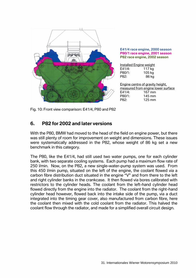
Fig. 10: Front view comparison: E41/4, P80 and P82
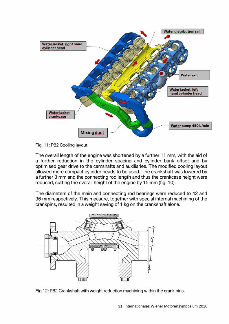
6. P82 for 2002 and later versions With the P80, BMW had moved to the head of the field on engine power, but there was still plenty of room for improvement on weight and dimensions. These issues were systematically addressed in the P82, whose weight of 86 kg set a new benchmark in this category. The P80, like the E41/4, had still used two water pumps, one for each cylinder bank, with two separate cooling systems. Each pump had a maximum flow rate of 250 l/min. Now, on the P82, a new single-water-pump system was used. From this 450 l/min pump, situated on the left of the engine, the coolant flowed via a carbon fibre distribution duct situated in the engine “V” and from there to the left and right cylinder banks in the crankcase. It then flowed via bores calibrated with restrictors to the cylinder heads. The coolant from the left-hand cylinder head flowed directly from the engine into the radiator. The coolant from the right-hand cylinder head however, flowed back into the intake side of the pump, via a duct integrated into the timing gear cover, also manufactured from carbon fibre, here the coolant then mixed with the cold coolant from the radiator. This halved the coolant flow through the radiator, and made for a simplified overall circuit design.
E41/4 race engine, 2000 season P80/1 race engine, 2001 season P82 race engine, 2002 season
Installed Engine weight E41/4: 117 kg P80/1: 105 kg P82: 86 kg
Engine centre of gravity height, measured from engine lower surface E41/4: 167 mm P80/1: 145 mm P82: 125 mm
- 11 -
31. Internationales Wiener Motorensymposium 2010
Fig. 11: P82 Cooling layout
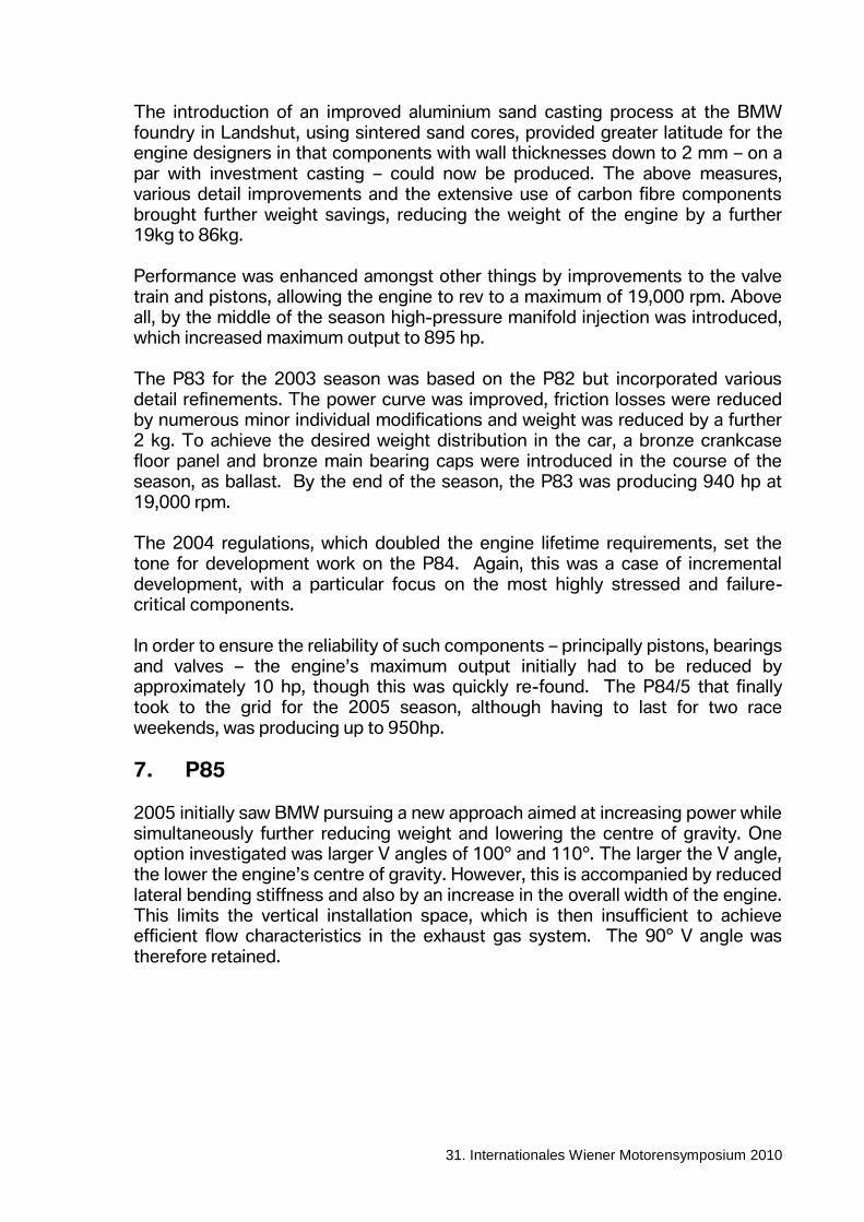
The overall length of the engine was shortened by a further 11 mm, with the aid of a further reduction in the cylinder spacing and cylinder bank offset and by optimised gear drive to the camshafts and auxiliaries. The modified cooling layout allowed more compact cylinder heads to be used. The crankshaft was lowered by a further 3 mm and the connecting rod length and thus the crankcase height were reduced, cutting the overall height of the engine by 15 mm (fig. 10). The diameters of the main and connecting rod bearings were reduced to 42 and 36 mm respectively. This measure, together with special internal machining of the crankpins, resulted in a weight saving of 1 kg on the crankshaft alone.
Fig 12: P82 Crankshaft with weight reduction machining within the crank pins.
- 12 -
31. Internationales Wiener Motorensymposium 2010
The introduction of an improved aluminium sand casting process at the BMW foundry in Landshut, using sintered sand cores, provided greater latitude for the engine designers in that components with wall thicknesses down to 2 mm – on a par with investment casting – could now be produced. The above measures, various detail improvements and the extensive use of carbon fibre components brought further weight savings, reducing the weight of the engine by a further 19kg to 86kg. Performance was enhanced amongst other things by improvements to the valve train and pistons, allowing the engine to rev to a maximum of 19,000 rpm. Above all, by the middle of the season high-pressure manifold injection was introduced, which increased maximum output to 895 hp. The P83 for the 2003 season was based on the P82 but incorporated various detail refinements. The power curve was improved, friction losses were reduced by numerous minor individual modifications and weight was reduced by a further 2 kg. To achieve the desired weight distribution in the car, a bronze crankcase floor panel and bronze main bearing caps were introduced in the course of the season, as ballast. By the end of the season, the P83 was producing 940 hp at 19,000 rpm. The 2004 regulations, which doubled the engine lifetime requirements, set the tone for development work on the P84. Again, this was a case of incremental development, with a particular focus on the most highly stressed and failure-critical components. In order to ensure the reliability of such components – principally pistons, bearings and valves – the engine’s maximum output initially had to be reduced by approximately 10 hp, though this was quickly re-found. The P84/5 that finally took to the grid for the 2005 season, although having to last for two race weekends, was producing up to 950hp.
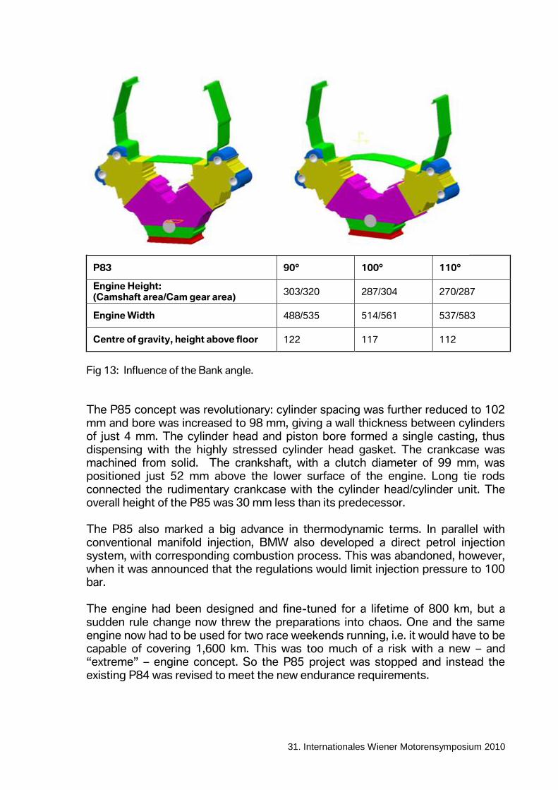
7. P85 2005 initially saw BMW pursuing a new approach aimed at increasing power while simultaneously further reducing weight and lowering the centre of gravity. One option investigated was larger V angles of 100° and 110°. The larger the V angle, the lower the engine’s centre of gravity. However, this is accompanied by reduced lateral bending stiffness and also by an increase in the overall width of the engine. This limits the vertical installation space, which is then insufficient to achieve efficient flow characteristics in the exhaust gas system. The 90° V angle was therefore retained.
- 13 -
31. Internationales Wiener Motorensymposium 2010
P83 90° 100° 110°
Engine Height: (Camshaft area/Cam gear area)
303/320 287/304 270/287
Engine Width 488/535 514/561 537/583
Centre of gravity, height above floor 122 117 112
Fig 13: Influence of the Bank angle.
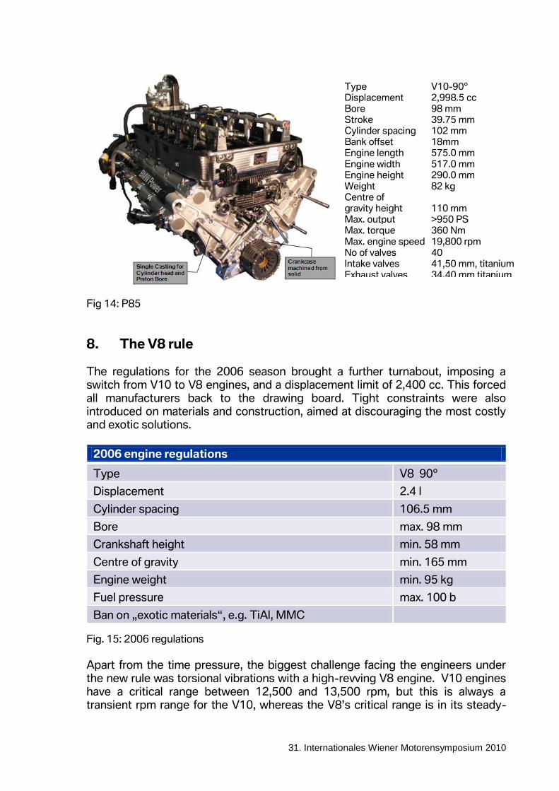
The P85 concept was revolutionary: cylinder spacing was further reduced to 102 mm and bore was increased to 98 mm, giving a wall thickness between cylinders of just 4 mm. The cylinder head and piston bore formed a single casting, thus dispensing with the highly stressed cylinder head gasket. The crankcase was machined from solid. The crankshaft, with a clutch diameter of 99 mm, was positioned just 52 mm above the lower surface of the engine. Long tie rods connected the rudimentary crankcase with the cylinder head/cylinder unit. The overall height of the P85 was 30 mm less than its predecessor. The P85 also marked a big advance in thermodynamic terms. In parallel with conventional manifold injection, BMW also developed a direct petrol injection system, with corresponding combustion process. This was abandoned, however, when it was announced that the regulations would limit injection pressure to 100 bar. The engine had been designed and fine-tuned for a lifetime of 800 km, but a sudden rule change now threw the preparations into chaos. One and the same engine now had to be used for two race weekends running, i.e. it would have to be capable of covering 1,600 km. This was too much of a risk with a new – and “extreme” – engine concept. So the P85 project was stopped and instead the existing P84 was revised to meet the new endurance requirements.
- 14 -
31. Internationales Wiener Motorensymposium 2010
Fig 14: P85
8. The V8 rule The regulations for the 2006 season brought a further turnabout, imposing a switch from V10 to V8 engines, and a displacement limit of 2,400 cc. This forced all manufacturers back to the drawing board. Tight constraints were also introduced on materials and construction, aimed at discouraging the most costly and exotic solutions.
2006 engine regulations
Type V8 90°
Displacement 2.4 l
Cylinder spacing 106.5 mm
Bore max. 98 mm
Crankshaft height min. 58 mm
Centre of gravity min. 165 mm
Engine weight min. 95 kg
Fuel pressure max. 100 b
Ban on „exotic materials“, e.g. TiAl, MMC
Fig. 15: 2006 regulations
Apart from the time pressure, the biggest challenge facing the engineers under the new rule was torsional vibrations with a high-revving V8 engine. V10 engines have a critical range between 12,500 and 13,500 rpm, but this is always a transient rpm range for the V10, whereas the V8’s critical range is in its steady-
Type V10-90° Displacement 2,998.5 cc Bore 98 mm Stroke 39.75 mm Cylinder spacing 102 mm Bank offset 18mm Engine length 575.0 mm
Engine width 517.0 mm Engine height 290.0 mm Weight 82 kg Centre of gravity height 110 mm Max. output >950 PS Max. torque 360 Nm
Max. engine speed 19,800 rpm No of valves 40 Intake valves 41,50 mm, titanium Exhaust valves 34.40 mm titanium
- 15 -
31. Internationales Wiener Motorensymposium 2010
state operating band over 17,000 rpm. Sorting out vibration issues was complicated by the fact that since V8 racing engines are always designed with a single-plane crankshaft due to gas exchange reasons, the free inertia forces are far higher than for the V10. This was compounded by the fact that, due to the lower power output, the proportion of time spent at full load was increased by 7%.
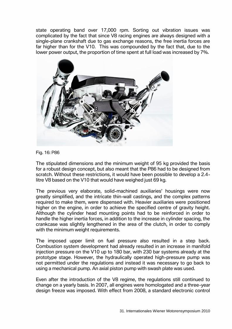
Fig. 16: P86
The stipulated dimensions and the minimum weight of 95 kg provided the basis for a robust design concept, but also meant that the P86 had to be designed from scratch. Without these restrictions, it would have been possible to develop a 2.4-litre V8 based on the V10 that would have weighed just 69 kg. The previous very elaborate, solid-machined auxiliaries’ housings were now greatly simplified, and the intricate thin-wall castings, and the complex patterns required to make them, were dispensed with. Heavier auxiliaries were positioned higher on the engine, in order to achieve the specified centre of gravity height. Although the cylinder head mounting points had to be reinforced in order to handle the higher inertia forces, in addition to the increase in cylinder spacing, the crankcase was slightly lengthened in the area of the clutch, in order to comply with the minimum weight requirements. The imposed upper limit on fuel pressure also resulted in a step back. Combustion system development had already resulted in an increase in manifold injection pressure on the V10 up to 180 bar, with 230 bar systems already at the prototype stage. However, the hydraulically operated high-pressure pump was not permitted under the regulations and instead it was necessary to go back to using a mechanical pump. An axial piston pump with swash plate was used. Even after the introduction of the V8 regime, the regulations still continued to change on a yearly basis. In 2007, all engines were homologated and a three-year design freeze was imposed. With effect from 2008, a standard electronic control
- 16 -
31. Internationales Wiener Motorensymposium 2010
unit was also specified. Finally, in 2009, the required engine lifetime was raised to 2,000 km, although with a simultaneous reduction in the rpm limit to 18,000 rpm. Despite the homologation, the following were permitted:
Development measures to remedy weaknesses and failure risks, subject to FIA approval
Adaptation of the gas exchange cycle to changes in rpm limits
Modifications to the engine periphery, e.g. intake and exhaust systems or fuel system.
An important part in increased performance and reliability are played by the operating fluids. Improvements to engine oil since the start of development work delivered a 4.5% increase in performance, while improvements in the fuel, where there are far tighter regulations, resulted in a 1% performance increase and a 2% improvement in consumption. However, this development potential has now been largely exhausted.
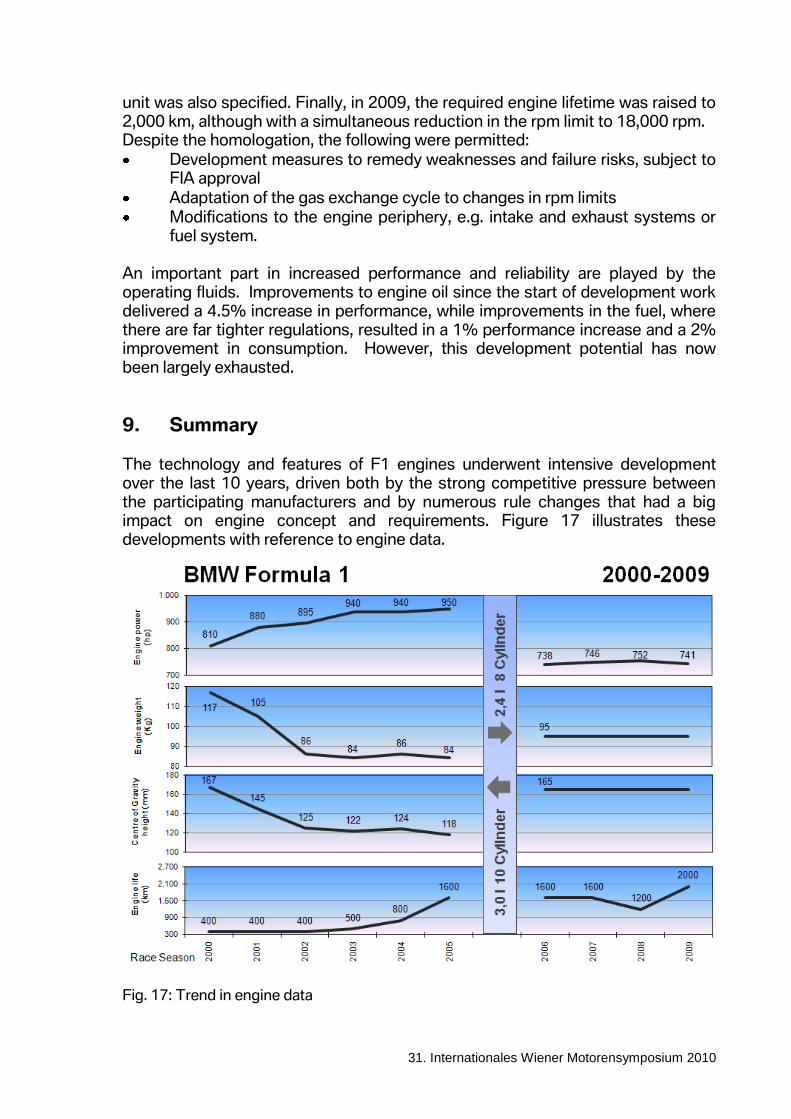
9. Summary The technology and features of F1 engines underwent intensive development over the last 10 years, driven both by the strong competitive pressure between the participating manufacturers and by numerous rule changes that had a big impact on engine concept and requirements. Figure 17 illustrates these developments with reference to engine data.
Fig. 17: Trend in engine data
- 17 -
31. Internationales Wiener Motorensymposium 2010
One of the biggest changes was the switch from the 3.0-litre V10 to the 2.4-litre V8: engine output fell by 20%, while weight and centre of gravity height increased, due to the imposition of minimum values. The effect of the restrictions can be seen by the fact that in 2006 a V8 engine designed without regard to regulations could theoretically have achieved a weight of 69 kg and a centre of gravity height of just 118mm. The robust construction imposed by the regulations, along with the 18,000 rpm engine speed limit, had benefits for engine lifetime and reliability: the engine with which Robert Kubica ended the 2009 season in Abu Dhabi had covered 2,000 km and taken part in four races. To compare once more, in 2000, a new engine was used every day, on Friday, Saturday and Sunday of a race weekend. A comparison between the P86/9 of 2009 and the E41/4 of early 2000 reveals an astonishing picture: the engine power of 750 hp is exactly the same, in other words the 20% reduction in displacement was fully offset. Also, despite the minimum weight regulation, weight fell by 20% while engine lifetime increased fivefold.
10. Outlook 2010 is the first season in eight years to see no changes to the engine regulations. The requirements on increased engine lifetime, the development freeze and the parallel introduction of testing restrictions have halved the budget for engine development, production and operation over the past years. The cost to achieve this was however high, caused by the unnecessarily large number of short term steps. If the conditions of competition really do remain stable for the next three years, further cost reductions can be expected. In 2013 a new generation of F1 engines is due to make its debut. These engines will reflect the latest development trends towards downsizing based on turbo charging, direct injection and energy recovery. Fuel efficiency will become an increasingly important competitive element. Hybrid components, such as the initially unsuccessful KERS system, will be introduced. A customer team will then procure not just an engine, but an integrated powertrain from a single source, comprising internal combustion engine, electric drive and storage system, gearbox and electronic control unit.