Embed Size (px)
Citation preview

Vinyl Acetate Monomer Process
287
10
10.1 Basis of Design
The vinyl acetate monomer (VAM) is large - scale commodity chemical mostly used in manufacturing polyvinyl acetate, the basic ingredient in water - soluble acrylic paints. Other applications are coatings for textile and paper industries, laminated safety glass, packaging, automotive fuel tanks and acrylic fi bers. The worldwide production of vinyl acetate was about 5 million tonnes per year in 2005, with rapid growth in the emerging markets. Higher effi ciency can be achieved by upstream integration with the production of low - cost acetic acid, as well as by downstream integration with the manufacturing of polyvinyl acetate and polyvinyl alcohol.
10.1.1 Manufacturing Routes
Three main routes for vinyl acetate manufacturing are employed today, as follows [1, 2] :
1. Acetic acid and acetylene The process is based on the reaction:
HC CH CH COOH H C CH-O- CO CH with KJ/mol≡ + → = = −3 2 3 118( ) ∆H
The operating conditions are gas phase at 170 – 250 ° C and Zn(OAc) 2 catalyst impregnated on charcoal. Per - pass acetylene conversion is 60 – 70% with a selec-tivity of 93% acetylene and 99% acetic acid. High acetylene cost and safety problems make this process less competitive today.
2. Acetaldehyde and acetic anhydride The process takes place in two stages. Firstly acetaldehyde and acetic anhydride
form ethylidene diacetate in liquid phase at 120 – 140 ° C with FeCl 3 as a catalyst:
CH CHO CH CO O CH CH OCOCH3 3 2 3 3 2+ →( ) ( )
Chemical Process Design: Computer-Aided Case Studies. Alexandre C. Dimian and Costin Sorin BildeaCopyright © 2008 WILEY-VCH Verlag GmbH & Co. KGaA, WeinheimISBN: 978-3-527-31403-4
288 10 Vinyl Acetate Monomer Process
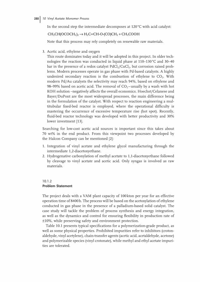
In the second step the intermediate decomposes at 120 ° C with acid catalyst:
CH CH OCOCH H C CH-O- CO CH CH COOH3 3 2 2 3 3( ) ( )→ = +
Note that this process may rely completely on renewable raw materials.
3. Acetic acid, ethylene and oxygen This route dominates today and it will be adopted in this project. In older tech-
nologies the reaction was conducted in liquid phase at 110 – 130 ° C and 30 – 40 bar in the presence of a redox catalyst PdCl 2 /CuCl 2 , but corrosion raised prob-lems. Modern processes operate in gas phase with Pd - based catalysts. A highly undesired secondary reaction is the combustion of ethylene to CO 2 . With modern Pd/Au catalysts the selectivity may reach 94%, based on ethylene and 98 – 99% based on acetic acid. The removal of CO 2 – usually by a wash with hot KOH solution – negatively affects the overall economics. Hoechst/Celanese and Bayer/DuPont are the most widespread processes, the main difference being in the formulation of the catalyst. With respect to reaction engineering a mul-titubular fi xed - bed reactor is employed, where the operational diffi culty is mastering the occurrence of excessive temperature rise (hot spot). Recently, fl uid - bed reactor technology was developed with better productivity and 30% lower investment [13] .
Searching for low - cost acetic acid sources is important since this takes about 70 wt% in the end product. From this viewpoint two processes developed by the Halcon Company can be mentioned [2] :
1. Integration of vinyl acetate and ethylene glycol manufacturing through the intermediate 1,2 - diacetoxyethane.
2. Hydrogenative carbonylation of methyl acetate to 1,1 - diacetoxyethane followed by cleavage to vinyl acetate and acetic acid. Only syngas is involved as raw materials.
10.1.2 Problem Statement
The project deals with a VAM plant capacity of 100 kton per year for an effective operation time of 8400 h. The process will be based on the acetoxylation of ethylene conducted in gas phase in the presence of a palladium - based solid catalyst. The case study will tackle the problem of process synthesis and energy integration, as well as the dynamics and control for ensuring fl exibility in production rate of ± 10%, while preserving safety and environment protection.
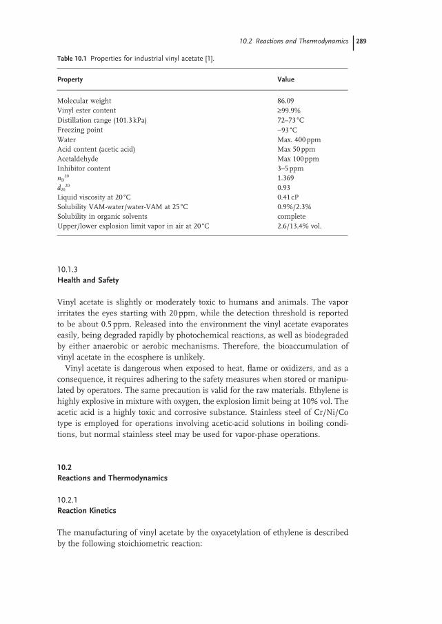
Table 10.1 presents typical specifi cations for a polymerization - grade product, as well as some physical properties. Prohibited impurities refer to inhibitors (croton-aldehyde, vinyl acetylene), chain - transfer agents (acetic acid, acetaldehyde, acetone) and polymerizable species (vinyl crotonate), while methyl and ethyl acetate impuri-ties are tolerated.
10.1.3 Health and Safety
Vinyl acetate is slightly or moderately toxic to humans and animals. The vapor irritates the eyes starting with 20 ppm, while the detection threshold is reported to be about 0.5 ppm. Released into the environment the vinyl acetate evaporates easily, being degraded rapidly by photochemical reactions, as well as biodegraded by either anaerobic or aerobic mechanisms. Therefore, the bioaccumulation of vinyl acetate in the ecosphere is unlikely.
Vinyl acetate is dangerous when exposed to heat, fl ame or oxidizers, and as a consequence, it requires adhering to the safety measures when stored or manipu-lated by operators. The same precaution is valid for the raw materials. Ethylene is highly explosive in mixture with oxygen, the explosion limit being at 10% vol. The acetic acid is a highly toxic and corrosive substance. Stainless steel of Cr/Ni/Co type is employed for operations involving acetic - acid solutions in boiling condi-tions, but normal stainless steel may be used for vapor - phase operations.
10.2 Reactions and Thermodynamics
10.2.1 Reaction Kinetics
The manufacturing of vinyl acetate by the oxyacetylation of ethylene is described by the following stoichiometric reaction:
Table 10.1 Properties for industrial vinyl acetate [1] .
Property Value
Molecular weight 86.09 Vinyl ester content ≥ 99.9% Distillation range (101.3 kPa) 72 – 73 ° C Freezing point − 93 ° C Water Max. 400 ppm Acid content (acetic acid) Max 50 ppm Acetaldehyde Max 100 ppm Inhibitor content 3 – 5 ppm n D 20 1.369 d 20 20 0.93 Liquid viscosity at 20 ° C 0.41 cP Solubility VAM - water/water - VAM at 25 ° C 0.9%/2.3% Solubility in organic solvents complete Upper/lower explosion limit vapor in air at 20 ° C 2.6/13.4% vol.
10.2 Reactions and Thermodynamics 289
290 10 Vinyl Acetate Monomer Process
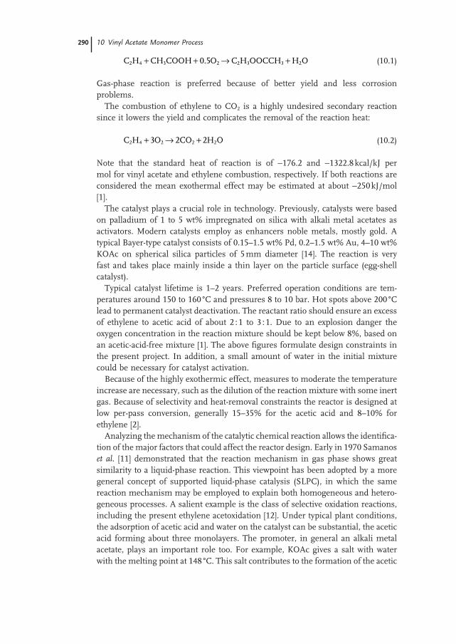
C H CH COOH O C H OOCCH H O2 4 3 2 2 3 3 20 5+ + → +. (10.1)
Gas - phase reaction is preferred because of better yield and less corrosion problems.
The combustion of ethylene to CO 2 is a highly undesired secondary reaction since it lowers the yield and complicates the removal of the reaction heat:
C H O CO H O2 4 2 2 23 2 2+ → + (10.2)
Note that the standard heat of reaction is of − 176.2 and − 1322.8 kcal/kJ per mol for vinyl acetate and ethylene combustion, respectively. If both reactions are considered the mean exothermal effect may be estimated at about − 250 kJ/mol [1] .
The catalyst plays a crucial role in technology. Previously, catalysts were based on palladium of 1 to 5 wt% impregnated on silica with alkali metal acetates as activators. Modern catalysts employ as enhancers noble metals, mostly gold. A typical Bayer - type catalyst consists of 0.15 – 1.5 wt% Pd, 0.2 – 1.5 wt% Au, 4 – 10 wt% KOAc on spherical silica particles of 5 mm diameter [14] . The reaction is very fast and takes place mainly inside a thin layer on the particle surface (egg - shell catalyst).
Typical catalyst lifetime is 1 – 2 years. Preferred operation conditions are tem-peratures around 150 to 160 ° C and pressures 8 to 10 bar. Hot spots above 200 ° C lead to permanent catalyst deactivation. The reactant ratio should ensure an excess of ethylene to acetic acid of about 2 : 1 to 3 : 1. Due to an explosion danger the oxygen concentration in the reaction mixture should be kept below 8%, based on an acetic - acid - free mixture [1] . The above fi gures formulate design constraints in the present project. In addition, a small amount of water in the initial mixture could be necessary for catalyst activation.
Because of the highly exothermic effect, measures to moderate the temperature increase are necessary, such as the dilution of the reaction mixture with some inert gas. Because of selectivity and heat - removal constraints the reactor is designed at low per - pass conversion, generally 15 – 35% for the acetic acid and 8 – 10% for ethylene [2] .
Analyzing the mechanism of the catalytic chemical reaction allows the identifi ca-tion of the major factors that could affect the reactor design. Early in 1970 Samanos et al . [11] demonstrated that the reaction mechanism in gas phase shows great similarity to a liquid - phase reaction. This viewpoint has been adopted by a more general concept of supported liquid - phase catalysis (SLPC), in which the same reaction mechanism may be employed to explain both homogeneous and hetero-geneous processes. A salient example is the class of selective oxidation reactions, including the present ethylene acetoxidation [12] . Under typical plant conditions, the adsorption of acetic acid and water on the catalyst can be substantial, the acetic acid forming about three monolayers. The promoter, in general an alkali metal acetate, plays an important role too. For example, KOAc gives a salt with water with the melting point at 148 ° C. This salt contributes to the formation of the acetic
acid layer, as described by the reaction KOAc + AcOH → KH(OAc) 2 , which further prevents the combustion of ethylene. Moreover, the KOAc enhances the formation of actives centers through the solvatation of palladium complexes as Pd(OAc) 2 + KOAc → KPd(OAc) 3 . Therefore, a probable reaction mechanism could be formu-lated as follows:
Pd O AcOH Pd OAc H O+ + ↔ +0 5 22 2 2. ( ) (1)
Pd OAc AcO Pd OAc( ) ( )2 3+ ↔− − (2)
Pd OAc C H VAM AcOH AcO Pd( )3 2 4− −+ ↔ + + + (3)
As a result, from a reactor - design viewpoint the reaction kinetics is not sensitive to the concentration of the acetic acid, but the presence of some water is necessary to activate the catalyst. On the contrary, ethylene and oxygen are involved in kinet-ics through a complex adsorption/surface - reaction mechanism. This behavior was confi rmed by both academic and industrial research [8, 9] .
Modern catalysts for vinyl - acetate synthesis contain Au in the chemical formula-tion, which manifests in much higher activity and selectivity. This is refl ected by fundamental changes in the kinetics, such as for example switching the reaction order of ethylene from negative to positive [8] . As a consequence, in more recent studies the formation of vinyl acetate can be described conveniently by a power - law kinetics involving only ethylene and oxygen:
r k p pVA C H O= 1 2 41
21α β (10.3)
The exponent α 1 is 0.35 – 0.38 and β 1 0.18 – 0.21 indicating strong adsorption limita-tions. The reaction constant is given by k 1 = A 1 exp( − E 1 / RT ) in which the energy of activation depends on the Pd content, for example 39 kJ/mol for Pd 1% and 17.3 kJ/mol for Pd 5%.
Similar kinetics has been found to describe the secondary combustion reaction, but with reaction orders very different from the main reaction:
r k p pCO C H O2 2 42
22
2= α β (10.4)
Table 10.2 presents the kinetic information for the main reactions, in which the frequency factors have been calculated from turnover - frequency (TOF) data [8, 9] . This term, borrowed from enzymatic catalysis, quantifi es the specifi c activity of a catalytic center. By defi nition, TOF gives the number of molecular reactions or catalytic cycles occurring at a center per unit of time. For a heterogeneous cata-lyst the number of active centers can be found by means of sorption methods. Let us consider that the active sites are due to a metal atom. By defi nition [15] we have:
TOF
volumetric rate of reaction
number of center/volume
mol= = ees_A
l_cat s
l_cat
moles_Me×= −s 1
(10.5)
10.2 Reactions and Thermodynamics 291
292 10 Vinyl Acetate Monomer Process
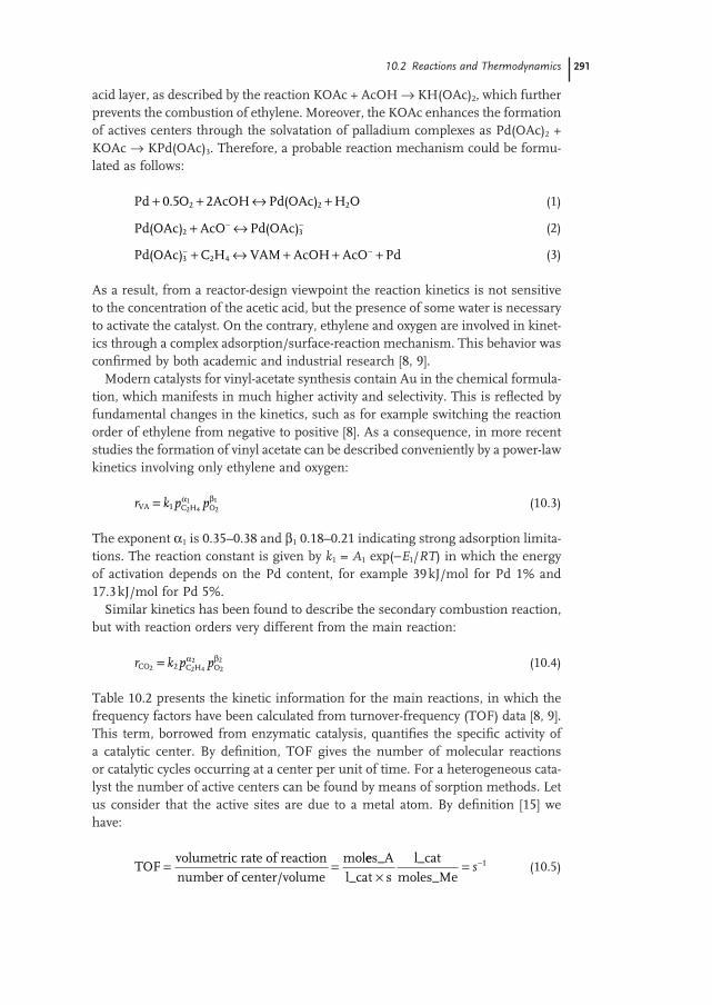
The catalyst is characterized by the metal weight fraction w Me with MW Me the atomic weight, the metal dispersion coeffi cients D giving the fraction of active centers, and ρ cat the grain catalyst density. By replacing into the relation (10.5) the following formula can be obtained for the calculation of TOF from kinetic experiments:
TOF
moles_A/s
l_cat g_Meg_cat MW
g_catl_cat
MWMe
A MeMe
=×
= ×
1D
R wD
(10.6)
Conversely, transforming TOF into reaction rate data can be done with the relation:
− = × × ×r wD
A MeMe
catTOFMW
ρ (10.7)
As an example, let us consider the reported value TOF = 6.5 × 10 – 3 s − 1 . Cata-lyst data are: ρ cat = 1000 g/l, MW Pd = 106.4, w Pd = 0.01, D = 0.4. One gets − r A = 6.5 × 10 – 3 × 0.01 × (0.4/106.4) × 1000 = 2.44 × 10 – 4 moles VA/l_cat/s = 2.10 × 10 – 2 g/l/s = 7.52 × 10 – 2 kg/l/h. Note that this TOF value is obtained at a low partial pressure of ethylene. In industrial conditions the pressure is an order of magnitude higher. Thus, the reaction rate would be about 0.7 kg/l/h. This value is in agreement with STY reported in some recent patents. For example, a modern Pd - gold catalyst on supported 4 – 6 mm silica spheres (patent US 649229931) gives a space - time yield (STP) of 700 g VAM/l/h and a selectivity of 92 – 94% at 150 ° C and 7.8 bar with a gas mixture of ethylene 53.1/acetic acid 10.4/oxygen 7.7 and inert 28.6 (vol.%).
Note that expressing the catalyst activity in terms of TOF allows tailoring the catalyst activity to the requirements of process design. Because the activation energy remains constant, the only affected parameter is the pre - exponential factor A , which in turn is proportional to the weight fraction of the active center, in this case the metal. Table 10.2 shows two situations. In the fi rst case the pre - exponential factor is taken from the original TOF data, which corresponds to a fast
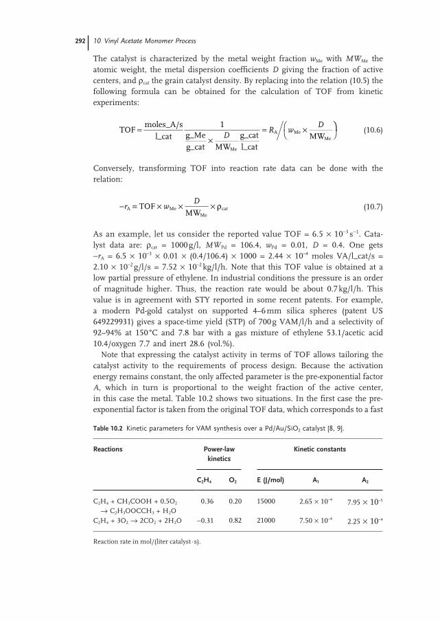
Table 10.2 Kinetic parameters for VAM synthesis over a Pd/Au/SiO 2 catalyst [8, 9] .
Reactions Power - law kinetics
Kinetic constants
C 2 H 4 O 2 E (J/mol) A 1 A 2
C 2 H 4 + CH 3 COOH + 0.5O 2 → C 2 H 3 OOCCH 3 + H 2 O
0.36 0.20 15000 2.65 × 10 – 4 7.95 × 10 – 5
C 2 H 4 + 3O 2 → 2CO 2 + 2H 2 O − 0.31 0.82 21000 7.50 × 10 – 4 2.25 × 10 – 4
Reaction rate in mol/(liter catalyst · s).
catalyst. Preliminary simulation showed that in this case the occurrence of hot spot is very likely. For this reason in the second case the catalyst activity is lowered by a factor of three, by less metal impregnation. This catalyst is adopted for the reactor design and fl owsheet simulation.
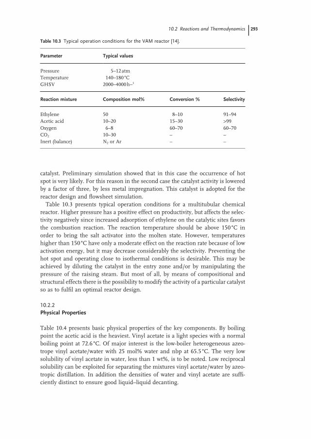
Table 10.3 presents typical operation conditions for a multitubular chemical reactor. Higher pressure has a positive effect on productivity, but affects the selec-tivity negatively since increased adsorption of ethylene on the catalytic sites favors the combustion reaction. The reaction temperature should be above 150 ° C in order to bring the salt activator into the molten state. However, temperatures higher than 150 ° C have only a moderate effect on the reaction rate because of low activation energy, but it may decrease considerably the selectivity. Preventing the hot spot and operating close to isothermal conditions is desirable. This may be achieved by diluting the catalyst in the entry zone and/or by manipulating the pressure of the raising steam. But most of all, by means of compositional and structural effects there is the possibility to modify the activity of a particular catalyst so as to fulfi l an optimal reactor design.
10.2.2 Physical Properties
Table 10.4 presents basic physical properties of the key components. By boiling point the acetic acid is the heaviest. Vinyl acetate is a light species with a normal boiling point at 72.6 ° C. Of major interest is the low - boiler heterogeneous azeo-trope vinyl acetate/water with 25 mol% water and nbp at 65.5 ° C. The very low solubility of vinyl acetate in water, less than 1 wt%, is to be noted. Low reciprocal solubility can be exploited for separating the mixtures vinyl acetate/water by azeo-tropic distillation. In addition the densities of water and vinyl acetate are suffi -ciently distinct to ensure good liquid – liquid decanting.
Table 10.3 Typical operation conditions for the VAM reactor [14] .
Parameter Typical values
Pressure 5 – 12 atm Temperature 140 – 180 ° C GHSV 2000 – 4000 h − 1
Reaction mixture Composition mol% Conversion % Selectivity
Ethylene 50 8 – 10 91 – 94 Acetic acid 10 – 20 15 – 30 > 99 Oxygen 6 – 8 60 – 70 60 – 70 CO 2 10 – 30 – – Inert (balance) N 2 or Ar – –
10.2 Reactions and Thermodynamics 293
294 10 Vinyl Acetate Monomer Process
10.2.3 VLE of Key Mixtures
It can be anticipated that the liquid - separation system should handle the mixture vinyl acetate/acetic acid/water. Figure 10.1 displays the residue curve map at 1 atm calculated by Aspen Split ™ [16] with the thermodynamic NRTL/HOC and VLLE option. The phase equilibrium is dominated by the binary heterogeneous azeo-trope vinyl acetate/water with the composition 0.745/0.255 mol% or 0.933/0.0667 wt% and boiling points at 65.6 ° C. It may be observed that the relative position of the azeotrope, as well as reciprocal solubility and the tie - line direction depend on the compositional coordinate, in molar or mass fractions, because of the large difference in the molar weight of the two components. The residue curve map suggests as a separation strategy the distillation in top of the VAM/water azeotrope followed by the separation of VAM by L – L decanting, while the acetic acid can be obtained as bottom product.
10.3 Input – Output Analysis
The selection of raw materials takes into account the price variation versus purity, with constraints on undesired species. Table 10.5 shows the choice. Acetic acid is of high purity with small amounts in acetaldehyde and formic acid. Ethylene is of high purity too, with severe specifi cations on CO and sulfur in order to protect the catalyst, but small amounts of ethane are allowed.
10.3.1 Preliminary Material Balance
Taking the acetic acid as reference, its molar feed is 100 000/8400/86 = 138.43 kmol/h, which is rounded further to 140 kmol/h. A key decision regards the selectivity.
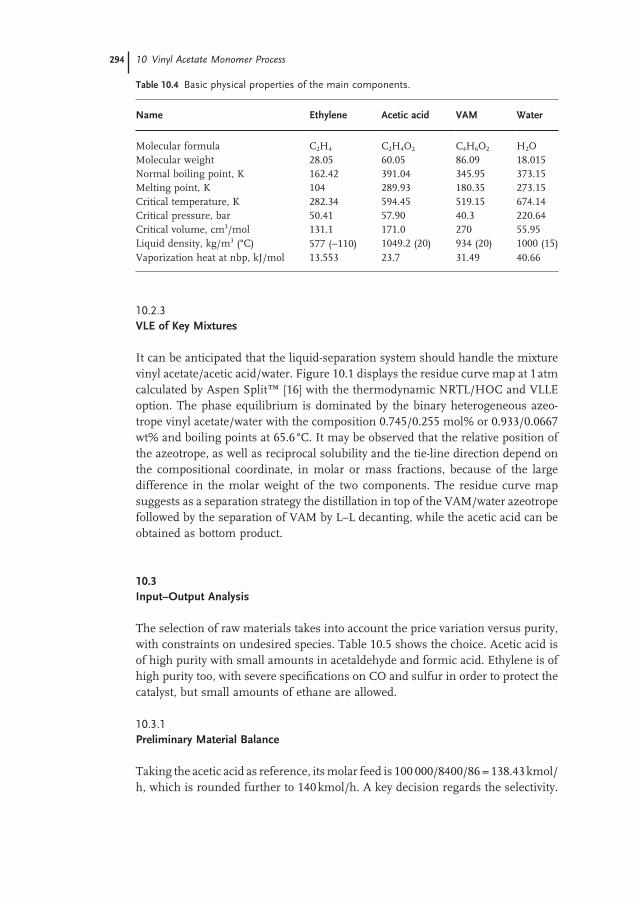
Table 10.4 Basic physical properties of the main components.
Name Ethylene Acetic acid VAM Water
Molecular formula C 2 H 4 C 2 H 4 O 2 C 4 H 6 O 2 H 2 O Molecular weight 28.05 60.05 86.09 18.015 Normal boiling point, K 162.42 391.04 345.95 373.15 Melting point, K 104 289.93 180.35 273.15 Critical temperature, K 282.34 594.45 519.15 674.14 Critical pressure, bar 50.41 57.90 40.3 220.64 Critical volume, cm 3 /mol 131.1 171.0 270 55.95 Liquid density, kg/m 3 ( ° C) 577 ( − 110) 1049.2 (20) 934 (20) 1000 (15) Vaporization heat at nbp, kJ/mol 13.553 23.7 31.49 40.66
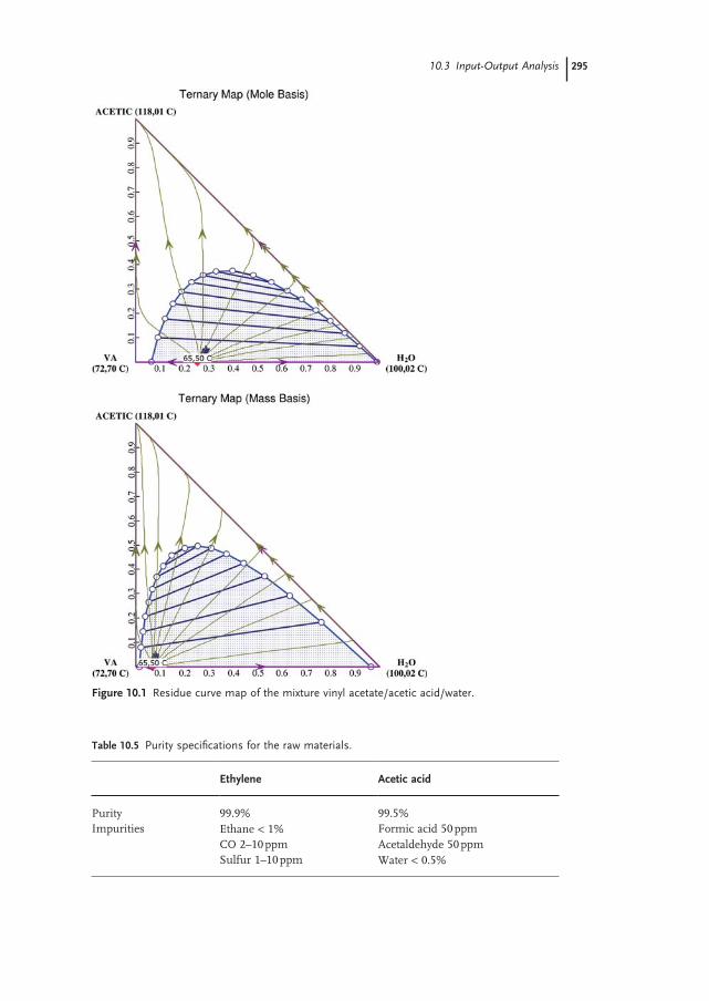
Figure 10.1 Residue curve map of the mixture vinyl acetate/acetic acid/water.
Table 10.5 Purity specifi cations for the raw materials.
Ethylene Acetic acid
Purity 99.9% 99.5% Impurities Ethane < 1% Formic acid 50 ppm
CO 2 – 10 ppm Acetaldehyde 50 ppm Sulfur 1 – 10 ppm Water < 0.5%
10.3 Input-Output Analysis 295
296 10 Vinyl Acetate Monomer Process
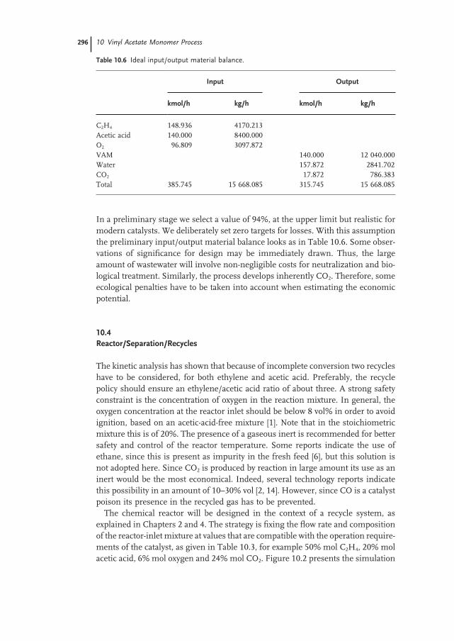
In a preliminary stage we select a value of 94%, at the upper limit but realistic for modern catalysts. We deliberately set zero targets for losses. With this assumption the preliminary input/output material balance looks as in Table 10.6 . Some obser-vations of signifi cance for design may be immediately drawn. Thus, the large amount of wastewater will involve non - negligible costs for neutralization and bio-logical treatment. Similarly, the process develops inherently CO 2 . Therefore, some ecological penalties have to be taken into account when estimating the economic potential.
10.4 Reactor/Separation/Recycles
The kinetic analysis has shown that because of incomplete conversion two recycles have to be considered, for both ethylene and acetic acid. Preferably, the recycle policy should ensure an ethylene/acetic acid ratio of about three. A strong safety constraint is the concentration of oxygen in the reaction mixture. In general, the oxygen concentration at the reactor inlet should be below 8 vol% in order to avoid ignition, based on an acetic - acid - free mixture [1] . Note that in the stoichiometric mixture this is of 20%. The presence of a gaseous inert is recommended for better safety and control of the reactor temperature. Some reports indicate the use of ethane, since this is present as impurity in the fresh feed [6] , but this solution is not adopted here. Since CO 2 is produced by reaction in large amount its use as an inert would be the most economical. Indeed, several technology reports indicate this possibility in an amount of 10 – 30% vol [2, 14] . However, since CO is a catalyst poison its presence in the recycled gas has to be prevented.
The chemical reactor will be designed in the context of a recycle system, as explained in Chapters 2 and 4 . The strategy is fi xing the fl ow rate and composition of the reactor - inlet mixture at values that are compatible with the operation require-ments of the catalyst, as given in Table 10.3 , for example 50% mol C 2 H 4 , 20% mol acetic acid, 6% mol oxygen and 24% mol CO 2 . Figure 10.2 presents the simulation
Table 10.6 Ideal input/output material balance.
Input Output
kmol/h kg/h kmol/h kg/h
C 2 H 4 148.936 4170.213 Acetic acid 140.000 8400.000 O 2 96.809 3097.872 VAM 140.000 12 040.000 Water 157.872 2841.702 CO 2 17.872 786.383 Total 385.745 15 668.085 315.745 15 668.085
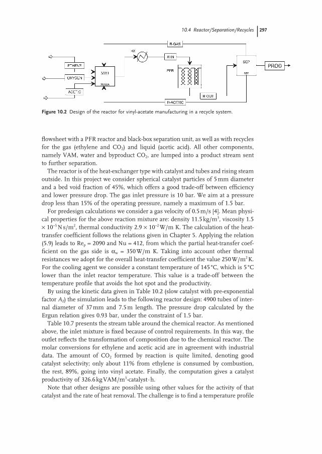
fl owsheet with a PFR reactor and black - box separation unit, as well as with recycles for the gas (ethylene and CO 2 ) and liquid (acetic acid). All other components, namely VAM, water and byproduct CO 2 , are lumped into a product stream sent to further separation.
The reactor is of the heat - exchanger type with catalyst and tubes and rising steam outside. In this project we consider spherical catalyst particles of 5 mm diameter and a bed void fraction of 45%, which offers a good trade - off between effi ciency and lower pressure drop. The gas inlet pressure is 10 bar. We aim at a pressure drop less than 15% of the operating pressure, namely a maximum of 1.5 bar.
For predesign calculations we consider a gas velocity of 0.5 m/s [4] . Mean physi-cal properties for the above reaction mixture are: density 11.5 kg/m 3 , viscosity 1.5 × 10 − 5 N s/m 2 , thermal conductivity 2.9 × 10 − 2 W/m K. The calculation of the heat - transfer coeffi cient follows the relations given in Chapter 5 . Applying the relation (5.9) leads to Re p = 2090 and Nu = 412, from which the partial heat - transfer coef-fi cient on the gas side is α w = 350 W/m K. Taking into account other thermal resistances we adopt for the overall heat - transfer coeffi cient the value 250 W/m 2 K. For the cooling agent we consider a constant temperature of 145 ° C, which is 5 ° C lower than the inlet reactor temperature. This value is a trade - off between the temperature profi le that avoids the hot spot and the productivity.
By using the kinetic data given in Table 10.2 (slow catalyst with pre - exponential factor A 2 ) the simulation leads to the following reactor design: 4900 tubes of inter-nal diameter of 37 mm and 7.5 m length. The pressure drop calculated by the Ergun relation gives 0.93 bar, under the constraint of 1.5 bar.
Table 10.7 presents the stream table around the chemical reactor. As mentioned above, the inlet mixture is fi xed because of control requirements. In this way, the outlet refl ects the transformation of composition due to the chemical reactor. The molar conversions for ethylene and acetic acid are in agreement with industrial data. The amount of CO 2 formed by reaction is quite limited, denoting good catalyst selectivity; only about 11% from ethylene is consumed by combustion, the rest, 89%, going into vinyl acetate. Finally, the computation gives a catalyst productivity of 326.6 kg VAM/m 3 - catalyst · h.
Note that other designs are possible using other values for the activity of that catalyst and the rate of heat removal. The challenge is to fi nd a temperature profi le
Figure 10.2 Design of the reactor for vinyl - acetate manufacturing in a recycle system.
10.4 Reactor/Separation/Recycles 297
298 10 Vinyl Acetate Monomer Process
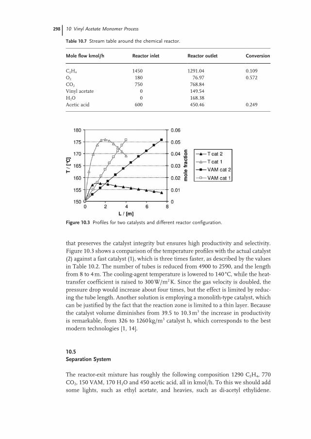
that preserves the catalyst integrity but ensures high productivity and selectivity. Figure 10.3 shows a comparison of the temperature profi les with the actual catalyst (2) against a fast catalyst (1), which is three times faster, as described by the values in Table 10.2 . The number of tubes is reduced from 4900 to 2590, and the length from 8 to 4 m. The cooling - agent temperature is lowered to 140 ° C, while the heat - transfer coeffi cient is raised to 300 W/m 2 K. Since the gas velocity is doubled, the pressure drop would increase about four times, but the effect is limited by reduc-ing the tube length. Another solution is employing a monolith - type catalyst, which can be justifi ed by the fact that the reaction zone is limited to a thin layer. Because the catalyst volume diminishes from 39.5 to 10.3 m 3 the increase in productivity is remarkable, from 326 to 1260 kg/m 3 catalyst h, which corresponds to the best modern technologies [1, 14] .
10.5 Separation System
The reactor - exit mixture has roughly the following composition 1290 C 2 H 4 , 770 CO 2 , 150 VAM, 170 H 2 O and 450 acetic acid, all in kmol/h. To this we should add some lights, such as ethyl acetate, and heavies, such as di - acetyl ethylidene.
Table 10.7 Stream table around the chemical reactor.
Mole fl ow kmol/h Reactor inlet Reactor outlet Conversion
C 2 H 4 1450 1291.04 0.109 O 2 180 76.97 0.572 CO 2 750 768.84 Vinyl acetate 0 149.54 H 2 O 0 168.38 Acetic acid 600 450.46 0.249
Figure 10.3 Profi les for two catalysts and different reactor confi guration.
However, these are disregarded since these should not affect the structure of the separations. The strategy consists of decomposing the separation problem in two subproblems, for gas and liquid separations, respectively, by designing a suitable fi rst separation step.
10.5.1 First Separation Step
To get an idea about the relative volatilities of components we proceed with a simple fl ash of the outlet reactor mixture at 33 ° C and 9 bar. The selection of the thermodynamic method is important since the mixture contains both supercritical and condensable components, some highly polar. From the gas - separation view-point an equation of state with capabilities for polar species should be the fi rst choice, as SR - Polar in Aspen Plus ™ [16] . From the liquid - separation viewpoint liquid - activity models are recommended, such as Wilson, NRTL or Uniquac, with the Hayden O ’ Connell option for handling the vapor - phase dimerization of the acetic acid [3] . Note that SR - Polar makes use of interaction parameters for C 2 H 4 , C 2 H 6 and CO 2 , but neglects the others, while the liquid - activity models account only for the interactions among vinyl acetate, acetic acid and water. To overcome this problem a mixed manner is selected, in which the condensable components are treated by a liquid - activity model and the gaseous species by the Henry law.
Table 10.8 presents a comparison of SR - Polar EOS and Wilson - HOC with Henry components. The predictions by the two methods are in good agreement, although surprisingly for the ability of SR - Polar to account for liquid - phase nonideality.
Because by single fl ash only two - thirds of the vinyl acetate passes in liquid phase, a multistage equilibrium separation is necessary for its advanced recovery, namely an absorption unit. A suitable solvent is the acetic acid itself. Consequently, after cooling the reaction gas is treated in countercurrent in the column (C - 1) with acetic acid fed on the top stage (Figure 10.4 ). To achieve higher recovery a liquid pump - around with intermediate cooling is employed. The simulation in Aspen Plus ™ [16] indicates that 20 stages are suffi cient for > 99.9% recovery with a pump - around between stages 4 and 2.
Table 10.8 Flash of the outlet reaction mixture at 9 bar and 33 ° C.
Species Molar fraction SR - Polar Wilson - HOC + Henry components
Initial Vapor Liquid Vapor Liquid
C 2 H 4 0.5400 0.5321 7.88E – 03 0.5398 1.23E – 04 O 2 0.0200 0.0199 3.95E – 05 0.0199 1.88E – 05 CO 2 0.2200 0.2136 6.33E – 03 0.2159 4.08E – 03 VAM 0.0428 5.67E – 03 0.0371 4.92E – 03 0.0379 H 2 O 0.0486 1.54E – 03 0.0470 1.32E – 03 0.0472 Acetic acid 0.1285 1.76E – 03 0.1268 2.15E – 03 0.1264
10.5 Separation System 299
300 10 Vinyl Acetate Monomer Process
10.5.2 Gas - Separation System
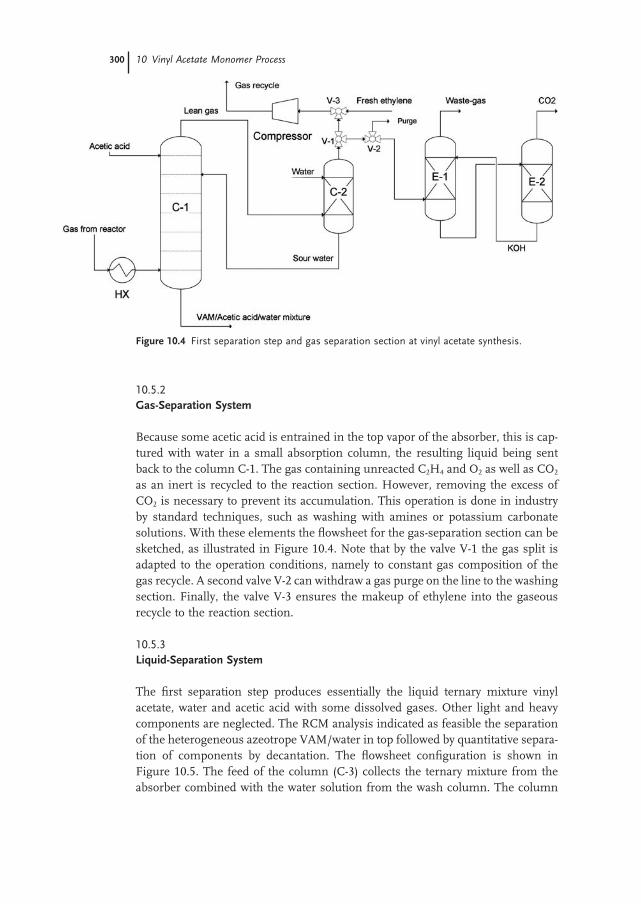
Because some acetic acid is entrained in the top vapor of the absorber, this is cap-tured with water in a small absorption column, the resulting liquid being sent back to the column C - 1. The gas containing unreacted C 2 H 4 and O 2 as well as CO 2 as an inert is recycled to the reaction section. However, removing the excess of CO 2 is necessary to prevent its accumulation. This operation is done in industry by standard techniques, such as washing with amines or potassium carbonate solutions. With these elements the fl owsheet for the gas - separation section can be sketched, as illustrated in Figure 10.4 . Note that by the valve V - 1 the gas split is adapted to the operation conditions, namely to constant gas composition of the gas recycle. A second valve V - 2 can withdraw a gas purge on the line to the washing section. Finally, the valve V - 3 ensures the makeup of ethylene into the gaseous recycle to the reaction section.
10.5.3 Liquid - Separation System
The fi rst separation step produces essentially the liquid ternary mixture vinyl acetate, water and acetic acid with some dissolved gases. Other light and heavy components are neglected. The RCM analysis indicated as feasible the separation of the heterogeneous azeotrope VAM/water in top followed by quantitative separa-tion of components by decantation. The fl owsheet confi guration is shown in Figure 10.5 . The feed of the column (C - 3) collects the ternary mixture from the absorber combined with the water solution from the wash column. The column
Figure 10.4 First separation step and gas separation section at vinyl acetate synthesis.
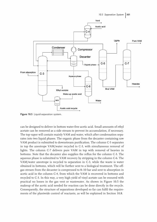
can be designed to deliver in bottom water - free acetic acid. Small amounts of ethyl acetate can be removed as a side stream to prevent its accumulation, if necessary. The top vapor will contain mainly VAM and water, which after condensation sepa-rates into two liquid phases. The organic phase from the decanter containing raw VAM product is submitted to downstream purifi cation. The column C - 5 separates in top the azeotrope VAM/water recycled to C - 3, with simultaneous removal of lights. The column C - 7 delivers pure VAM in top with removal of heavies in bottoms. Note that the decanter also supplies the refl ux for the column C - 3. The aqueous phase is submitted to VAM recovery by stripping in the column C - 6. The VAM/water azeotrope is recycled to separation in C - 3, while the waste is water obtained in bottoms, which will be further sent to a biological treatment. The off - gas stream from the decanter is compressed to 8 – 10 bar and sent to absorption in acetic acid in the column C - 4, from which the VAM is recovered in bottoms and recycled to C - 3. In this way, a very high yield of vinyl acetate can be ensured with practical no losses in the gas vent or wastewater. As shown in Figure 10.5 the makeup of the acetic acid needed for reaction can be done directly in the recycle. Consequently, the structure of separations developed so far can fulfi l the require-ments of the plantwide control of reactants, as will be explained in Section 10.8 .
Figure 10.5 Liquid - separation system.
10.5 Separation System 301
302 10 Vinyl Acetate Monomer Process
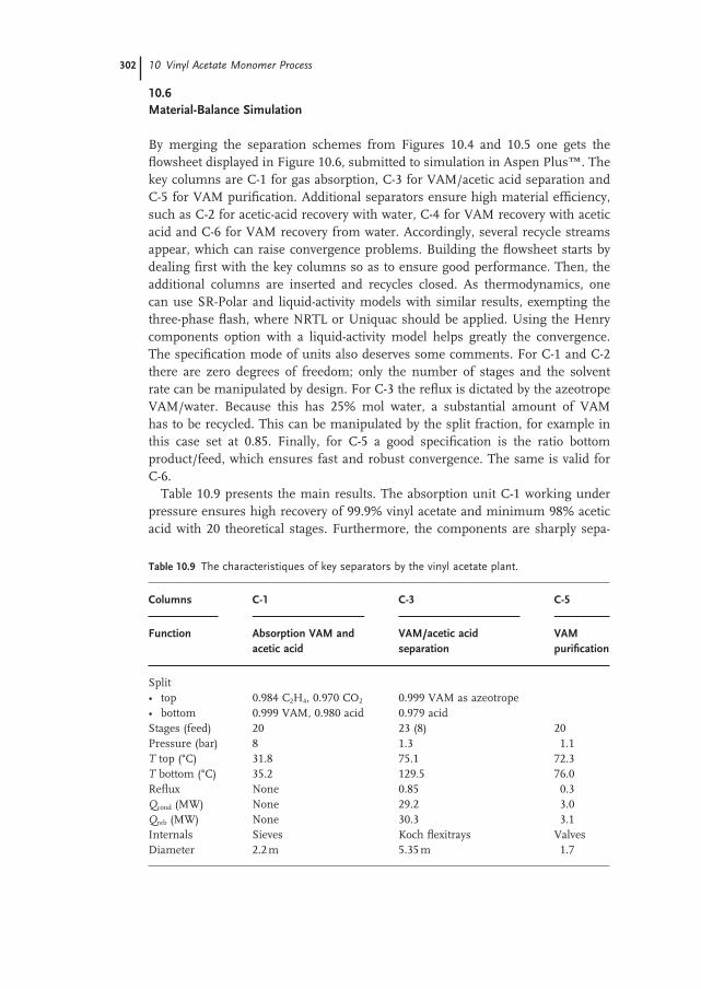
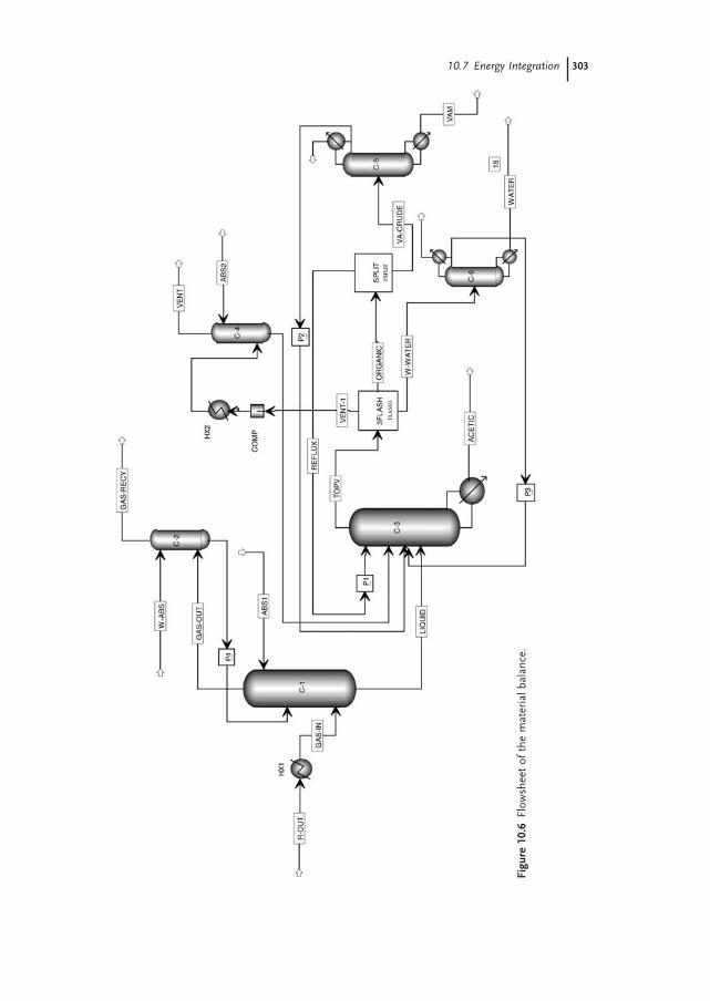
10.6 Material - Balance Simulation
By merging the separation schemes from Figures 10.4 and 10.5 one gets the fl owsheet displayed in Figure 10.6 , submitted to simulation in Aspen Plus ™ . The key columns are C - 1 for gas absorption, C - 3 for VAM/acetic acid separation and C - 5 for VAM purifi cation. Additional separators ensure high material effi ciency, such as C - 2 for acetic - acid recovery with water, C - 4 for VAM recovery with acetic acid and C - 6 for VAM recovery from water. Accordingly, several recycle streams appear, which can raise convergence problems. Building the fl owsheet starts by dealing fi rst with the key columns so as to ensure good performance. Then, the additional columns are inserted and recycles closed. As thermodynamics, one can use SR - Polar and liquid - activity models with similar results, exempting the three - phase fl ash, where NRTL or Uniquac should be applied. Using the Henry components option with a liquid - activity model helps greatly the convergence. The specifi cation mode of units also deserves some comments. For C - 1 and C - 2 there are zero degrees of freedom; only the number of stages and the solvent rate can be manipulated by design. For C - 3 the refl ux is dictated by the azeotrope VAM/water. Because this has 25% mol water, a substantial amount of VAM has to be recycled. This can be manipulated by the split fraction, for example in this case set at 0.85. Finally, for C - 5 a good specifi cation is the ratio bottom product/feed, which ensures fast and robust convergence. The same is valid for C - 6.
Table 10.9 presents the main results. The absorption unit C - 1 working under pressure ensures high recovery of 99.9% vinyl acetate and minimum 98% acetic acid with 20 theoretical stages. Furthermore, the components are sharply sepa-
Table 10.9 The characteristiques of key separators by the vinyl acetate plant.
Columns C - 1 C - 3 C - 5
Function Absorption VAM and acetic acid
VAM/acetic acid separation
VAM purifi cation
Split • top 0.984 C 2 H 4 , 0.970 CO 2 0.999 VAM as azeotrope • bottom 0.999 VAM, 0.980 acid 0.979 acid Stages (feed) 20 23 (8) 20 Pressure (bar) 8 1.3 1.1 T top ( ° C) 31.8 75.1 72.3 T bottom ( ° C) 35.2 129.5 76.0 Refl ux None 0.85 0.3 Q cond (MW) None 29.2 3.0 Q reb (MW) None 30.3 3.1 Internals Sieves Koch fl exitrays Valves Diameter 2.2 m 5.35 m 1.7
10.7 Energy Integration 303
Figu
re 1
0.6
Flow
shee
t of
the
mat
eria
l bal
ance
.
304 10 Vinyl Acetate Monomer Process
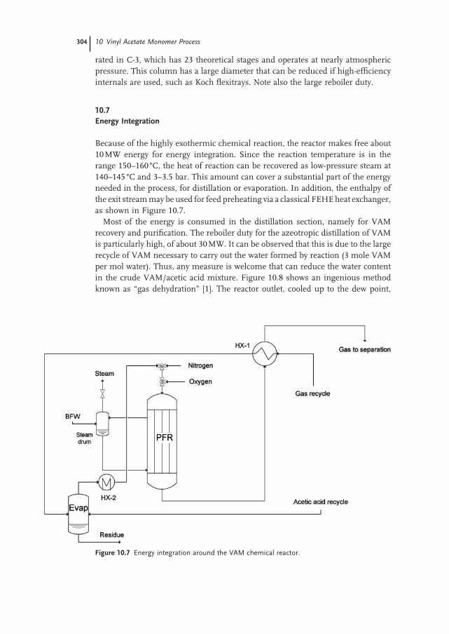
Figure 10.7 Energy integration around the VAM chemical reactor.
rated in C - 3, which has 23 theoretical stages and operates at nearly atmospheric pressure. This column has a large diameter that can be reduced if high - effi ciency internals are used, such as Koch fl exitrays. Note also the large reboiler duty.
10.7 Energy Integration
Because of the highly exothermic chemical reaction, the reactor makes free about 10 MW energy for energy integration. Since the reaction temperature is in the range 150 – 160 ° C, the heat of reaction can be recovered as low - pressure steam at 140 – 145 ° C and 3 – 3.5 bar. This amount can cover a substantial part of the energy needed in the process, for distillation or evaporation. In addition, the enthalpy of the exit stream may be used for feed preheating via a classical FEHE heat exchanger, as shown in Figure 10.7 .
Most of the energy is consumed in the distillation section, namely for VAM recovery and purifi cation. The reboiler duty for the azeotropic distillation of VAM is particularly high, of about 30 MW. It can be observed that this is due to the large recycle of VAM necessary to carry out the water formed by reaction (3 mole VAM per mol water). Thus, any measure is welcome that can reduce the water content in the crude VAM/acetic acid mixture. Figure 10.8 shows an ingenious method known as “ gas dehydration ” [1] . The reactor outlet, cooled up to the dew point,
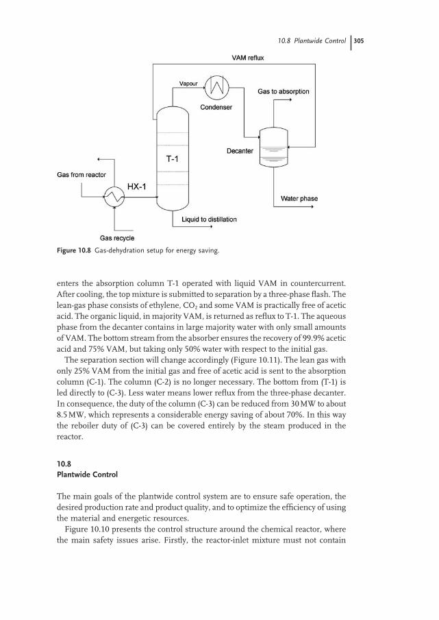
Figure 10.8 Gas - dehydration setup for energy saving.
10.8 Plantwide Control 305
enters the absorption column T - 1 operated with liquid VAM in countercurrent. After cooling, the top mixture is submitted to separation by a three - phase fl ash. The lean - gas phase consists of ethylene, CO 2 and some VAM is practically free of acetic acid. The organic liquid, in majority VAM, is returned as refl ux to T - 1. The aqueous phase from the decanter contains in large majority water with only small amounts of VAM. The bottom stream from the absorber ensures the recovery of 99.9% acetic acid and 75% VAM, but taking only 50% water with respect to the initial gas.
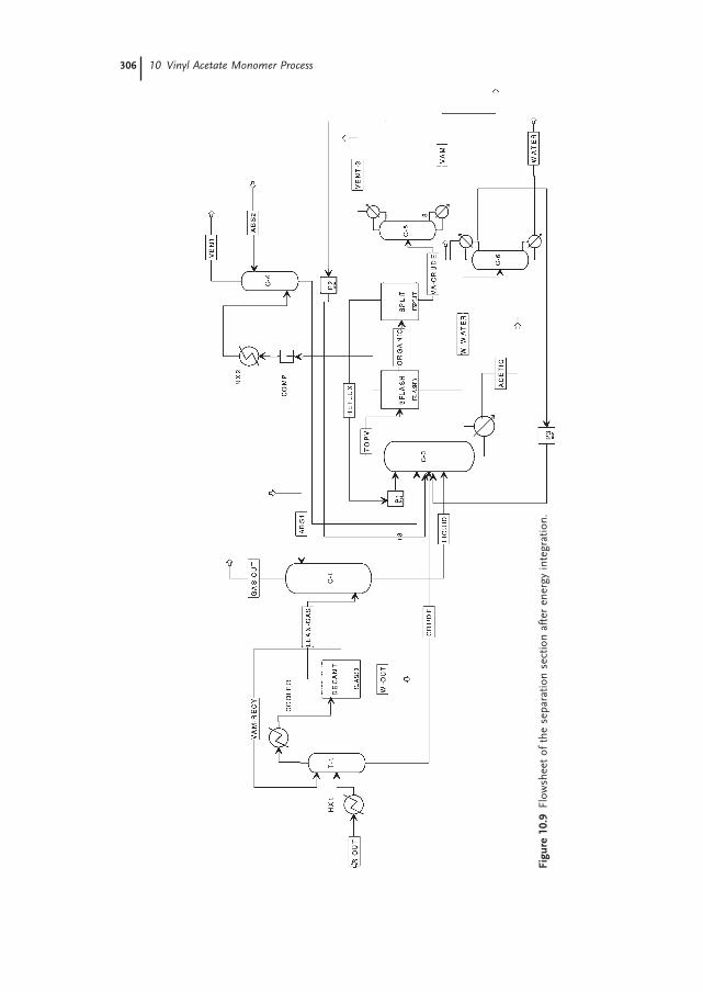
The separation section will change accordingly (Figure 10.11 ). The lean gas with only 25% VAM from the initial gas and free of acetic acid is sent to the absorption column (C - 1). The column (C - 2) is no longer necessary. The bottom from (T - 1) is led directly to (C - 3). Less water means lower refl ux from the three - phase decanter. In consequence, the duty of the column (C - 3) can be reduced from 30 MW to about 8.5 MW, which represents a considerable energy saving of about 70%. In this way the reboiler duty of (C - 3) can be covered entirely by the steam produced in the reactor.
10.8 Plantwide Control
The main goals of the plantwide control system are to ensure safe operation, the desired production rate and product quality, and to optimize the effi ciency of using the material and energetic resources.
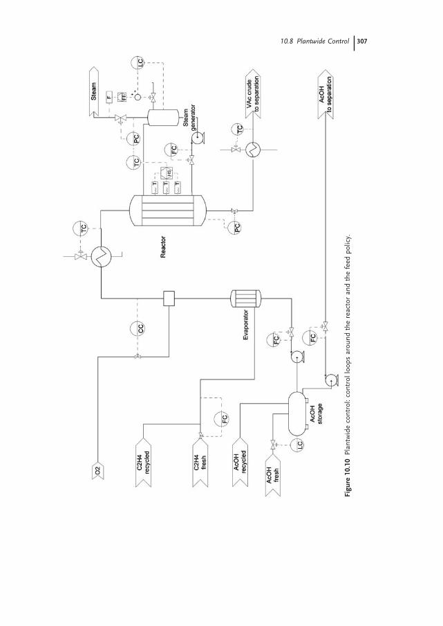
Figure 10.10 presents the control structure around the chemical reactor, where the main safety issues arise. Firstly, the reactor - inlet mixture must not contain
306 10 Vinyl Acetate Monomer Process
Figu
re 1
0.9
Flow
shee
t of
the
sep
arat
ion
sect
ion
afte
r en
ergy
inte
grat
ion.
Figu
re 1
0.10
Pla
ntw
ide
cont
rol:
cont
rol l
oops
aro
und
the
reac
tor
and
the
feed
pol
icy.
10.8 Plantwide Control 307
308 10 Vinyl Acetate Monomer Process
more than 8% oxygen base in the acid - free mixture in order to avoid explosion risks. Therefore, the oxygen is added under concentration control, in a mixing chamber placed behind concrete walls. Secondly, the cooling should avoid reaction runaway. In a runaway situation, the excessive temperature leads to the danger of explosion, catalyst deactivation, and a drastic decrease of the selectivity. The coolant is circulated at a constant rate. Several temperature measurements are placed along the reactor bed and the highest value is selected as the process variable. The manipulated variable of the control loop is the steam - generator pressure, which directly infl uences the coolant temperature. The water level in the steam generator is controlled by the water makeup. Note that using a simple feedback loop may not work. When the steam rate increases, the correct action is to add more water makeup. However, the pressure simultaneously decreases. The lower pressure means that, initially, the steam bubbles will occupy a larger volume, and the liquid level will increase. A feedback level controller will wrongly decrease the water makeup rate. Therefore, the steam rate is measured and the required water makeup is calculated. This feedforward action is combined with the feedback provided by the level controller.
As recommended in Chapter 4 , the inventory of reactants in the plant is main-tained by fi xing the reactor - inlet fl ows. Acetic acid is taken with constant rate from a storage tank, and the fresh feed is added on level control. The gas rate going to the evaporator is a good estimation of the ethylene inventory. Therefore, this fl ow is kept constant by adjusting the fresh ethylene feed. The fresh oxygen rate is manipulated by a concentration control loop, as previously explained.
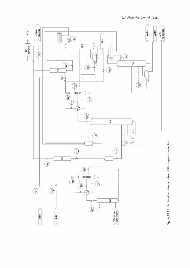
The control of the separation section is presented in Figure 10.11 . Although the fl owsheet seems complex, the control is rather simple. The separation must deliver recycle and product streams with the required purity: acetic acid (from C - 3), vinyl acetate (from C - 5) and water (from C - 6). Because the distillate streams are recycled within the separation section, their composition is less important. Therefore, columns C - 3, C - 5 and C - 6 are operated at constant refl ux, while boilup rates are used to control some temperatures in the lower sections of the column. For the absorption columns C - 1 and C - 4, the fl ow rates of the absorbent (acetic acid) are kept constant. The concentration of CO 2 in the recycle stream is controlled by changing the amount of gas sent to the CO 2 removal unit. The additional level, temperature and pressure control loops are standard.
In Chapter 4 , two ways for achieving production - rate changes were presented. The fi rst strategy, manipulating the reactor inlet fl ows, does not work here. The acetic acid does not infl uence the reaction rate, the per - pass conversion of ethylene is very low (10%), while the reactor - inlet oxygen concentration is restricted by the safety concerns. Therefore, the second strategy of manipulating the reaction condi-tions should be applied.
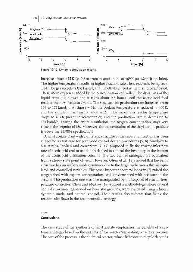
The reactor model available in Aspen Dynamics ™ [16] only provides the possi-bility of changing the coolant temperature. Figure 10.12 shows results dynamic simulation results, for the following scenario: the plant is operated at the nominal steady state for 1 h. Then, the coolant temperature is increased from 413 to 425 K and simulation is continued for 2 h. The maximum temperature inside the reactor
Figu
re 1
0.11
Pla
ntw
ide
cont
rol:
cont
rol o
f th
e se
para
tion
sect
ion.
10.8 Plantwide Control 309
310 10 Vinyl Acetate Monomer Process
increases from 455 K (at 0.8 m from reactor inlet) to 469 K (at 1.2 m from inlet). The higher temperature results in higher reaction rates, less reactants being recy-cled. The gas recycle is the fastest, and the ethylene feed is the fi rst to be adjusted. Then, more oxygen is added by the concentration controller. The dynamics of the liquid recycle is slower and it takes about 0.5 hours until the acetic acid feed reaches the new stationary value. The vinyl acetate production - rate increases from 154 to 171 kmol/h. At time t = 3 h, the coolant temperature is reduced to 400 K, and the simulation is run for another 2 h. The maximum reactor temperature drops to 452 K (near the reactor inlet) and the production rate is decreased to 134 kmol/h. During the entire simulation, the oxygen concentration stays very close to the setpoint of 6%. Moreover, the concentration of the vinyl acetate product is above the 99.98% specifi cation.
A vinyl acetate plant with a different structure of the separation section has been suggested as test case for plantwide control design procedures [5, 6] . Similarly to our results, Luyben and co - workers [7, 17] proposed to fi x the reactor - inlet fl ow rate of acetic acid and to use the fresh feed to control the inventory in the bottom of the acetic - acid distillation column. The two control strategies are equivalent from a steady state point of view. However, Olsen et al. [18] showed that Luyben’s structure has an unfavourable dynamics due to the large lag between the manipu-lated and controlled variables. The other important control loops in [7] paired the oxygen feed with oxygen concentration, and ethylene feed with pressure in the system. The production rate was also manipulated by the setpoint of reactor tem-perature controller. Chen and McAvoy [19] applied a methodology where several control structures, generated on heuristic grounds, were evaluated using a linear dynamic model and optimal control. Their results also indicate that fi xing the reactor - inlet fl ows is the recommended strategy.
10.9 Conclusions
The case study of the synthesis of vinyl acetate emphasizes the benefi ts of a sys-tematic design based on the analysis of the reactor/separation/recycles structure. The core of the process is the chemical reactor, whose behavior in recycle depends
Figure 10.12 Dynamic simulation results.
References 311
on the kinetics and selectivity performance of the catalyst, as well as the safety and technological constraints. Moreover, the recycle policy depends on the reaction mechanism of the catalytic reaction.
Thus, for palladium/Au catalysts the adsorption of the acetic acid on the active sites is fast and not rate limiting, while ethylene and oxygen are involved through a LHHW mechanism. In consequence, the designer should respect the composi-tion of the reaction mixture at the reactor inlet that is compatible with the experi-mental conditions in which the kinetics of the catalytic process has been studied. From the reactor - design viewpoint this implies keeping the recycles of reactants, ethylene and acetic constant on a ratio of 3 – 4 : 1, while oxygen is made up to the maximum limit allowed by safety reasons. Because of selectivity reasons, low per - pass conversion has to be kept for both ethylene and acetic acid. The secondary combustion reaction can be limited by keeping both the pressure and temperature on the lower side. Two designs are compared, for slow and fast catalysts. Produc-tivity higher than 1000 kg VAM/m 3 catalyst h can be achieved working at higher temperature and shorter residence time, as well as with good temperature control.
The separation section takes advantage of the heterogeneous azeotrope formed by vinyl acetate and water, with very low reciprocal solubility. However, because of lower water content the recovery of VAM requires a high refl ux rate and a large amount of energy. Signifi cant energy saving, up to 70%, can be obtained by making use of a dehydration gas pretreatment. In this way, the exothermic reaction can cover up to 90% from the energy requirements of the distillations.
The approach in steady - state reactor design fi nds a dynamic equivalent in the plantwide control strategy. Because low per - pass conversion of both ethylene and acetic acid, manipulating the reactant feed to the reactor has little power in adjusting the production rate. The reaction temperature profi le becomes the main variable for manipulating the reaction rate and hence ensuring the fl exibility in production. The inventory of reactants is adapted accordingly by fresh reactant makeup directly in recycles. This approach can be seen as generic for low per - pass reactions.
References
1 Roscher , G. , Vinyl esters in Ullmans ’ s Encyclopedia of Industrial Chemistry , Wiley - VCH, Weinheim, Germany , 2002
2 Weissermel , K. , Arpe , H. J. , Industrial Organic Chemistry , 4th edn , Wiley - VCH, Weinheim, Germany , 2003
3 Dimian , A. C. , Integrated Simulation and Design of Chemical Processes , CACE series, No. 13, Elsevier, Amsterdam, The Netherlands , 2003
4 Rase , H. F. , Fixed - based Reactor Design and Diagnosis , Butterworth, Boston, USA , 1990
5 Chen , R. , Dave , K. , McAvoy , T. J. , A nonlinear dynamic model of a vinyl acetate process , Ind. Eng. Chem. Res. , 42 , 4478 – 4487 , 2003
6 Luyben , W. , Tyreus , B. , An industrial design/control study for vinyl acetate monomer plant , Comput. Chem. Eng. , 22 , 867 , 1998
7 Luyben , W. , Tyreus , B. , Luyben , M. , Plantwide Process Control , McGraw - Hill, New York, USA , 1999
8 Han , Y. F. , Wang J. H. , Kumar , D. , Yan , Z. , Goodman D. W. , A kinetic study of